US8017035B2 - Silicate-based yellow-green phosphors - Google Patents
Silicate-based yellow-green phosphors Download PDFInfo
- Publication number
- US8017035B2 US8017035B2 US11/963,994 US96399407A US8017035B2 US 8017035 B2 US8017035 B2 US 8017035B2 US 96399407 A US96399407 A US 96399407A US 8017035 B2 US8017035 B2 US 8017035B2
- Authority
- US
- United States
- Prior art keywords
- phosphor
- light
- yellow
- phosphors
- emission
- Prior art date
- Legal status (The legal status is an assumption and is not a legal conclusion. Google has not performed a legal analysis and makes no representation as to the accuracy of the status listed.)
- Expired - Fee Related, expires
Links
- BPQQTUXANYXVAA-UHFFFAOYSA-N Orthosilicate Chemical compound [O-][Si]([O-])([O-])[O-] BPQQTUXANYXVAA-UHFFFAOYSA-N 0.000 title abstract description 51
- OAICVXFJPJFONN-UHFFFAOYSA-N Phosphorus Chemical compound [P] OAICVXFJPJFONN-UHFFFAOYSA-N 0.000 claims abstract description 227
- 229910052731 fluorine Inorganic materials 0.000 claims abstract description 51
- 229910052788 barium Inorganic materials 0.000 claims abstract description 43
- 229910052791 calcium Inorganic materials 0.000 claims abstract description 42
- 229910052712 strontium Inorganic materials 0.000 claims abstract description 42
- 239000002019 doping agent Substances 0.000 claims abstract description 27
- 229910052725 zinc Inorganic materials 0.000 claims abstract description 25
- 229910052801 chlorine Inorganic materials 0.000 claims abstract description 23
- 229910052749 magnesium Inorganic materials 0.000 claims abstract description 22
- 229910052757 nitrogen Inorganic materials 0.000 claims abstract description 20
- 229910052793 cadmium Inorganic materials 0.000 claims abstract description 18
- 229910052909 inorganic silicate Inorganic materials 0.000 claims abstract description 18
- 229910052796 boron Inorganic materials 0.000 claims abstract description 14
- 229910052717 sulfur Inorganic materials 0.000 claims abstract description 13
- 229910052794 bromium Inorganic materials 0.000 claims abstract description 8
- 229910052740 iodine Inorganic materials 0.000 claims abstract description 8
- 229910015840 BaxMy Inorganic materials 0.000 claims abstract description 7
- 230000005855 radiation Effects 0.000 claims description 61
- 229910016310 MxSiy Inorganic materials 0.000 claims description 7
- 239000005132 Calcium sulfide based phosphorescent agent Substances 0.000 claims description 6
- 150000001875 compounds Chemical class 0.000 abstract description 22
- 150000002500 ions Chemical class 0.000 abstract description 12
- 229910052751 metal Inorganic materials 0.000 abstract description 9
- 239000002184 metal Substances 0.000 abstract description 9
- 229910052698 phosphorus Inorganic materials 0.000 abstract description 9
- 239000011575 calcium Substances 0.000 description 52
- 239000000203 mixture Substances 0.000 description 45
- YCKRFDGAMUMZLT-UHFFFAOYSA-N Fluorine atom Chemical compound [F] YCKRFDGAMUMZLT-UHFFFAOYSA-N 0.000 description 38
- 239000011737 fluorine Substances 0.000 description 38
- 238000005286 illumination Methods 0.000 description 38
- 230000005284 excitation Effects 0.000 description 37
- 239000011777 magnesium Substances 0.000 description 31
- JNDMLEXHDPKVFC-UHFFFAOYSA-N aluminum;oxygen(2-);yttrium(3+) Chemical class [O-2].[O-2].[O-2].[Al+3].[Y+3] JNDMLEXHDPKVFC-UHFFFAOYSA-N 0.000 description 27
- 239000000463 material Substances 0.000 description 27
- 238000000034 method Methods 0.000 description 26
- 229910019901 yttrium aluminum garnet Inorganic materials 0.000 description 26
- 239000000460 chlorine Substances 0.000 description 24
- 150000001450 anions Chemical class 0.000 description 23
- 230000006870 function Effects 0.000 description 19
- 238000002156 mixing Methods 0.000 description 19
- 238000001228 spectrum Methods 0.000 description 19
- 238000010586 diagram Methods 0.000 description 18
- -1 halogen ion Chemical class 0.000 description 17
- 239000011701 zinc Substances 0.000 description 17
- IJGRMHOSHXDMSA-UHFFFAOYSA-N Atomic nitrogen Chemical compound N#N IJGRMHOSHXDMSA-UHFFFAOYSA-N 0.000 description 16
- 239000000243 solution Substances 0.000 description 15
- 238000000295 emission spectrum Methods 0.000 description 14
- 238000009877 rendering Methods 0.000 description 14
- 230000000694 effects Effects 0.000 description 13
- LDDQLRUQCUTJBB-UHFFFAOYSA-N ammonium fluoride Chemical compound [NH4+].[F-] LDDQLRUQCUTJBB-UHFFFAOYSA-N 0.000 description 12
- 238000006243 chemical reaction Methods 0.000 description 12
- 239000012298 atmosphere Substances 0.000 description 11
- 150000001768 cations Chemical class 0.000 description 11
- 239000013078 crystal Substances 0.000 description 11
- 150000004767 nitrides Chemical class 0.000 description 11
- 150000004760 silicates Chemical class 0.000 description 11
- 239000007858 starting material Substances 0.000 description 11
- QVGXLLKOCUKJST-UHFFFAOYSA-N atomic oxygen Chemical compound [O] QVGXLLKOCUKJST-UHFFFAOYSA-N 0.000 description 10
- 230000008901 benefit Effects 0.000 description 10
- 238000005090 crystal field Methods 0.000 description 10
- 238000000695 excitation spectrum Methods 0.000 description 10
- 229910052760 oxygen Inorganic materials 0.000 description 10
- 239000001301 oxygen Substances 0.000 description 10
- VYPSYNLAJGMNEJ-UHFFFAOYSA-N Silicium dioxide Chemical compound O=[Si]=O VYPSYNLAJGMNEJ-UHFFFAOYSA-N 0.000 description 9
- 229910019990 cerium-doped yttrium aluminum garnet Inorganic materials 0.000 description 9
- 238000005245 sintering Methods 0.000 description 9
- 230000004907 flux Effects 0.000 description 8
- 238000004519 manufacturing process Methods 0.000 description 8
- 239000000843 powder Substances 0.000 description 8
- 229910052782 aluminium Inorganic materials 0.000 description 7
- 238000002474 experimental method Methods 0.000 description 7
- 238000010304 firing Methods 0.000 description 7
- 229910052710 silicon Inorganic materials 0.000 description 7
- 238000006467 substitution reaction Methods 0.000 description 7
- MCSXGCZMEPXKIW-UHFFFAOYSA-N 3-hydroxy-4-[(4-methyl-2-nitrophenyl)diazenyl]-N-(3-nitrophenyl)naphthalene-2-carboxamide Chemical compound Cc1ccc(N=Nc2c(O)c(cc3ccccc23)C(=O)Nc2cccc(c2)[N+]([O-])=O)c(c1)[N+]([O-])=O MCSXGCZMEPXKIW-UHFFFAOYSA-N 0.000 description 6
- QGZKDVFQNNGYKY-UHFFFAOYSA-N Ammonia Chemical compound N QGZKDVFQNNGYKY-UHFFFAOYSA-N 0.000 description 6
- XUIMIQQOPSSXEZ-UHFFFAOYSA-N Silicon Chemical compound [Si] XUIMIQQOPSSXEZ-UHFFFAOYSA-N 0.000 description 6
- XAGFODPZIPBFFR-UHFFFAOYSA-N aluminium Chemical compound [Al] XAGFODPZIPBFFR-UHFFFAOYSA-N 0.000 description 6
- 239000003086 colorant Substances 0.000 description 6
- 238000004020 luminiscence type Methods 0.000 description 6
- 239000010703 silicon Substances 0.000 description 6
- 239000007787 solid Substances 0.000 description 6
- 229910052688 Gadolinium Inorganic materials 0.000 description 5
- 229910001615 alkaline earth metal halide Inorganic materials 0.000 description 5
- 125000004429 atom Chemical group 0.000 description 5
- DSAJWYNOEDNPEQ-UHFFFAOYSA-N barium atom Chemical compound [Ba] DSAJWYNOEDNPEQ-UHFFFAOYSA-N 0.000 description 5
- 229910001632 barium fluoride Inorganic materials 0.000 description 5
- 238000001354 calcination Methods 0.000 description 5
- 238000001035 drying Methods 0.000 description 5
- 239000000499 gel Substances 0.000 description 5
- CIOAGBVUUVVLOB-UHFFFAOYSA-N strontium atom Chemical compound [Sr] CIOAGBVUUVVLOB-UHFFFAOYSA-N 0.000 description 5
- ZAMOUSCENKQFHK-UHFFFAOYSA-N Chlorine atom Chemical compound [Cl] ZAMOUSCENKQFHK-UHFFFAOYSA-N 0.000 description 4
- 229910052693 Europium Inorganic materials 0.000 description 4
- 229910002601 GaN Inorganic materials 0.000 description 4
- 238000010521 absorption reaction Methods 0.000 description 4
- 229910052784 alkaline earth metal Inorganic materials 0.000 description 4
- 229910021529 ammonia Inorganic materials 0.000 description 4
- 238000013459 approach Methods 0.000 description 4
- 230000000875 corresponding effect Effects 0.000 description 4
- 230000007423 decrease Effects 0.000 description 4
- OGPBJKLSAFTDLK-UHFFFAOYSA-N europium atom Chemical compound [Eu] OGPBJKLSAFTDLK-UHFFFAOYSA-N 0.000 description 4
- RSEIMSPAXMNYFJ-UHFFFAOYSA-N europium(III) oxide Inorganic materials O=[Eu]O[Eu]=O RSEIMSPAXMNYFJ-UHFFFAOYSA-N 0.000 description 4
- 238000000227 grinding Methods 0.000 description 4
- 150000004820 halides Chemical class 0.000 description 4
- 230000006872 improvement Effects 0.000 description 4
- 125000004433 nitrogen atom Chemical group N* 0.000 description 4
- 230000003287 optical effect Effects 0.000 description 4
- 230000008569 process Effects 0.000 description 4
- 239000004065 semiconductor Substances 0.000 description 4
- 238000003980 solgel method Methods 0.000 description 4
- 238000012360 testing method Methods 0.000 description 4
- 229910052727 yttrium Inorganic materials 0.000 description 4
- OYPRJOBELJOOCE-UHFFFAOYSA-N Calcium Chemical compound [Ca] OYPRJOBELJOOCE-UHFFFAOYSA-N 0.000 description 3
- FYYHWMGAXLPEAU-UHFFFAOYSA-N Magnesium Chemical group [Mg] FYYHWMGAXLPEAU-UHFFFAOYSA-N 0.000 description 3
- OKKJLVBELUTLKV-UHFFFAOYSA-N Methanol Chemical compound OC OKKJLVBELUTLKV-UHFFFAOYSA-N 0.000 description 3
- 150000001342 alkaline earth metals Chemical class 0.000 description 3
- 150000004645 aluminates Chemical class 0.000 description 3
- 230000008859 change Effects 0.000 description 3
- 150000002178 europium compounds Chemical class 0.000 description 3
- 229910052732 germanium Inorganic materials 0.000 description 3
- GNPVGFCGXDBREM-UHFFFAOYSA-N germanium atom Chemical compound [Ge] GNPVGFCGXDBREM-UHFFFAOYSA-N 0.000 description 3
- 239000011572 manganese Substances 0.000 description 3
- 150000002823 nitrates Chemical class 0.000 description 3
- 238000012545 processing Methods 0.000 description 3
- 239000000377 silicon dioxide Substances 0.000 description 3
- 230000003595 spectral effect Effects 0.000 description 3
- 230000007704 transition Effects 0.000 description 3
- 229910000789 Aluminium-silicon alloy Inorganic materials 0.000 description 2
- NLXLAEXVIDQMFP-UHFFFAOYSA-N Ammonia chloride Chemical compound [NH4+].[Cl-] NLXLAEXVIDQMFP-UHFFFAOYSA-N 0.000 description 2
- LFQSCWFLJHTTHZ-UHFFFAOYSA-N Ethanol Chemical compound CCO LFQSCWFLJHTTHZ-UHFFFAOYSA-N 0.000 description 2
- KRHYYFGTRYWZRS-UHFFFAOYSA-M Fluoride anion Chemical compound [F-] KRHYYFGTRYWZRS-UHFFFAOYSA-M 0.000 description 2
- 229910019142 PO4 Inorganic materials 0.000 description 2
- WCUXLLCKKVVCTQ-UHFFFAOYSA-M Potassium chloride Chemical compound [Cl-].[K+] WCUXLLCKKVVCTQ-UHFFFAOYSA-M 0.000 description 2
- FAPWRFPIFSIZLT-UHFFFAOYSA-M Sodium chloride Chemical compound [Na+].[Cl-] FAPWRFPIFSIZLT-UHFFFAOYSA-M 0.000 description 2
- 239000005084 Strontium aluminate Substances 0.000 description 2
- 229910052771 Terbium Inorganic materials 0.000 description 2
- XLOMVQKBTHCTTD-UHFFFAOYSA-N Zinc monoxide Chemical compound [Zn]=O XLOMVQKBTHCTTD-UHFFFAOYSA-N 0.000 description 2
- 150000001341 alkaline earth metal compounds Chemical class 0.000 description 2
- 229910000287 alkaline earth metal oxide Inorganic materials 0.000 description 2
- 230000005540 biological transmission Effects 0.000 description 2
- 230000015572 biosynthetic process Effects 0.000 description 2
- 150000004649 carbonic acid derivatives Chemical class 0.000 description 2
- 239000003795 chemical substances by application Substances 0.000 description 2
- 229910052681 coesite Inorganic materials 0.000 description 2
- 230000000295 complement effect Effects 0.000 description 2
- 238000001816 cooling Methods 0.000 description 2
- 229910052906 cristobalite Inorganic materials 0.000 description 2
- 230000007547 defect Effects 0.000 description 2
- 239000008367 deionised water Substances 0.000 description 2
- 238000005401 electroluminescence Methods 0.000 description 2
- 238000004993 emission spectroscopy Methods 0.000 description 2
- NNMXSTWQJRPBJZ-UHFFFAOYSA-K europium(iii) chloride Chemical compound Cl[Eu](Cl)Cl NNMXSTWQJRPBJZ-UHFFFAOYSA-K 0.000 description 2
- 238000001704 evaporation Methods 0.000 description 2
- 230000008020 evaporation Effects 0.000 description 2
- 239000002223 garnet Substances 0.000 description 2
- 239000007789 gas Substances 0.000 description 2
- 239000012535 impurity Substances 0.000 description 2
- KWGKDLIKAYFUFQ-UHFFFAOYSA-M lithium chloride Chemical compound [Li+].[Cl-] KWGKDLIKAYFUFQ-UHFFFAOYSA-M 0.000 description 2
- PQXKHYXIUOZZFA-UHFFFAOYSA-M lithium fluoride Chemical compound [Li+].[F-] PQXKHYXIUOZZFA-UHFFFAOYSA-M 0.000 description 2
- 230000007246 mechanism Effects 0.000 description 2
- 239000003960 organic solvent Substances 0.000 description 2
- NBIIXXVUZAFLBC-UHFFFAOYSA-K phosphate Chemical compound [O-]P([O-])([O-])=O NBIIXXVUZAFLBC-UHFFFAOYSA-K 0.000 description 2
- 239000011574 phosphorus Substances 0.000 description 2
- NROKBHXJSPEDAR-UHFFFAOYSA-M potassium fluoride Chemical compound [F-].[K+] NROKBHXJSPEDAR-UHFFFAOYSA-M 0.000 description 2
- 238000010791 quenching Methods 0.000 description 2
- 230000000171 quenching effect Effects 0.000 description 2
- 230000004044 response Effects 0.000 description 2
- 229910002027 silica gel Inorganic materials 0.000 description 2
- 239000000741 silica gel Substances 0.000 description 2
- 150000003377 silicon compounds Chemical class 0.000 description 2
- PUZPDOWCWNUUKD-UHFFFAOYSA-M sodium fluoride Chemical compound [F-].[Na+] PUZPDOWCWNUUKD-UHFFFAOYSA-M 0.000 description 2
- 239000002904 solvent Substances 0.000 description 2
- 238000003756 stirring Methods 0.000 description 2
- 229910052682 stishovite Inorganic materials 0.000 description 2
- 230000000153 supplemental effect Effects 0.000 description 2
- 229910052905 tridymite Inorganic materials 0.000 description 2
- HPNURIVGONRLQI-UHFFFAOYSA-K trifluoroeuropium Chemical compound F[Eu](F)F HPNURIVGONRLQI-UHFFFAOYSA-K 0.000 description 2
- PFNQVRZLDWYSCW-UHFFFAOYSA-N (fluoren-9-ylideneamino) n-naphthalen-1-ylcarbamate Chemical compound C12=CC=CC=C2C2=CC=CC=C2C1=NOC(=O)NC1=CC=CC2=CC=CC=C12 PFNQVRZLDWYSCW-UHFFFAOYSA-N 0.000 description 1
- DDFHBQSCUXNBSA-UHFFFAOYSA-N 5-(5-carboxythiophen-2-yl)thiophene-2-carboxylic acid Chemical compound S1C(C(=O)O)=CC=C1C1=CC=C(C(O)=O)S1 DDFHBQSCUXNBSA-UHFFFAOYSA-N 0.000 description 1
- 241000566146 Asio Species 0.000 description 1
- 229910011255 B2O3 Inorganic materials 0.000 description 1
- ZOXJGFHDIHLPTG-UHFFFAOYSA-N Boron Chemical compound [B] ZOXJGFHDIHLPTG-UHFFFAOYSA-N 0.000 description 1
- FGUUSXIOTUKUDN-IBGZPJMESA-N C1(=CC=CC=C1)N1C2=C(NC([C@H](C1)NC=1OC(=NN=1)C1=CC=CC=C1)=O)C=CC=C2 Chemical compound C1(=CC=CC=C1)N1C2=C(NC([C@H](C1)NC=1OC(=NN=1)C1=CC=CC=C1)=O)C=CC=C2 FGUUSXIOTUKUDN-IBGZPJMESA-N 0.000 description 1
- UXVMQQNJUSDDNG-UHFFFAOYSA-L Calcium chloride Chemical compound [Cl-].[Cl-].[Ca+2] UXVMQQNJUSDDNG-UHFFFAOYSA-L 0.000 description 1
- 229910052684 Cerium Inorganic materials 0.000 description 1
- JMASRVWKEDWRBT-UHFFFAOYSA-N Gallium nitride Chemical compound [Ga]#N JMASRVWKEDWRBT-UHFFFAOYSA-N 0.000 description 1
- UFHFLCQGNIYNRP-UHFFFAOYSA-N Hydrogen Chemical compound [H][H] UFHFLCQGNIYNRP-UHFFFAOYSA-N 0.000 description 1
- 229910052765 Lutetium Inorganic materials 0.000 description 1
- PWHULOQIROXLJO-UHFFFAOYSA-N Manganese Chemical compound [Mn] PWHULOQIROXLJO-UHFFFAOYSA-N 0.000 description 1
- 229910002651 NO3 Inorganic materials 0.000 description 1
- NHNBFGGVMKEFGY-UHFFFAOYSA-N Nitrate Chemical compound [O-][N+]([O-])=O NHNBFGGVMKEFGY-UHFFFAOYSA-N 0.000 description 1
- GRYLNZFGIOXLOG-UHFFFAOYSA-N Nitric acid Chemical compound O[N+]([O-])=O GRYLNZFGIOXLOG-UHFFFAOYSA-N 0.000 description 1
- 229910052581 Si3N4 Inorganic materials 0.000 description 1
- NINIDFKCEFEMDL-UHFFFAOYSA-N Sulfur Chemical compound [S] NINIDFKCEFEMDL-UHFFFAOYSA-N 0.000 description 1
- 238000002441 X-ray diffraction Methods 0.000 description 1
- OSTULDXPMCGEOM-UHFFFAOYSA-N [O-][Ge](F)=O.[O-][Ge](F)=O.O[Ge](F)=O.O[Ge](F)=O.O[Ge](F)=O.[Mg+2].P Chemical compound [O-][Ge](F)=O.[O-][Ge](F)=O.O[Ge](F)=O.O[Ge](F)=O.O[Ge](F)=O.[Mg+2].P OSTULDXPMCGEOM-UHFFFAOYSA-N 0.000 description 1
- 239000002253 acid Substances 0.000 description 1
- 239000012190 activator Substances 0.000 description 1
- 239000003513 alkali Substances 0.000 description 1
- 229910045601 alloy Inorganic materials 0.000 description 1
- 239000000956 alloy Substances 0.000 description 1
- FNCIDSNKNZQJTJ-UHFFFAOYSA-N alumane;terbium Chemical compound [AlH3].[Tb] FNCIDSNKNZQJTJ-UHFFFAOYSA-N 0.000 description 1
- 235000019270 ammonium chloride Nutrition 0.000 description 1
- LFVGISIMTYGQHF-UHFFFAOYSA-N ammonium dihydrogen phosphate Chemical compound [NH4+].OP(O)([O-])=O LFVGISIMTYGQHF-UHFFFAOYSA-N 0.000 description 1
- 229910052787 antimony Inorganic materials 0.000 description 1
- 229910052785 arsenic Inorganic materials 0.000 description 1
- WDIHJSXYQDMJHN-UHFFFAOYSA-L barium chloride Chemical compound [Cl-].[Cl-].[Ba+2] WDIHJSXYQDMJHN-UHFFFAOYSA-L 0.000 description 1
- 229910001626 barium chloride Inorganic materials 0.000 description 1
- OYLGJCQECKOTOL-UHFFFAOYSA-L barium fluoride Chemical compound [F-].[F-].[Ba+2] OYLGJCQECKOTOL-UHFFFAOYSA-L 0.000 description 1
- XBJJRSFLZVLCSE-UHFFFAOYSA-N barium(2+);diborate Chemical compound [Ba+2].[Ba+2].[Ba+2].[O-]B([O-])[O-].[O-]B([O-])[O-] XBJJRSFLZVLCSE-UHFFFAOYSA-N 0.000 description 1
- KGBXLFKZBHKPEV-UHFFFAOYSA-N boric acid Chemical compound OB(O)O KGBXLFKZBHKPEV-UHFFFAOYSA-N 0.000 description 1
- 239000004327 boric acid Substances 0.000 description 1
- 150000001639 boron compounds Chemical class 0.000 description 1
- 229910001628 calcium chloride Inorganic materials 0.000 description 1
- 239000001110 calcium chloride Substances 0.000 description 1
- WUKWITHWXAAZEY-UHFFFAOYSA-L calcium difluoride Chemical compound [F-].[F-].[Ca+2] WUKWITHWXAAZEY-UHFFFAOYSA-L 0.000 description 1
- 229910001634 calcium fluoride Inorganic materials 0.000 description 1
- GWXLDORMOJMVQZ-UHFFFAOYSA-N cerium Chemical compound [Ce] GWXLDORMOJMVQZ-UHFFFAOYSA-N 0.000 description 1
- 125000001309 chloro group Chemical group Cl* 0.000 description 1
- GTDCAOYDHVNFCP-UHFFFAOYSA-N chloro(trihydroxy)silane Chemical compound O[Si](O)(O)Cl GTDCAOYDHVNFCP-UHFFFAOYSA-N 0.000 description 1
- 239000002131 composite material Substances 0.000 description 1
- 238000010276 construction Methods 0.000 description 1
- 230000001276 controlling effect Effects 0.000 description 1
- 230000002596 correlated effect Effects 0.000 description 1
- 230000001419 dependent effect Effects 0.000 description 1
- 238000013461 design Methods 0.000 description 1
- JKWMSGQKBLHBQQ-UHFFFAOYSA-N diboron trioxide Chemical compound O=BOB=O JKWMSGQKBLHBQQ-UHFFFAOYSA-N 0.000 description 1
- XPPKVPWEQAFLFU-UHFFFAOYSA-J diphosphate(4-) Chemical compound [O-]P([O-])(=O)OP([O-])([O-])=O XPPKVPWEQAFLFU-UHFFFAOYSA-J 0.000 description 1
- 235000011180 diphosphates Nutrition 0.000 description 1
- 238000007580 dry-mixing Methods 0.000 description 1
- 230000005274 electronic transitions Effects 0.000 description 1
- 238000005516 engineering process Methods 0.000 description 1
- 229910001940 europium oxide Inorganic materials 0.000 description 1
- AEBZCFFCDTZXHP-UHFFFAOYSA-N europium(3+);oxygen(2-) Chemical compound [O-2].[O-2].[O-2].[Eu+3].[Eu+3] AEBZCFFCDTZXHP-UHFFFAOYSA-N 0.000 description 1
- 230000003203 everyday effect Effects 0.000 description 1
- 230000001747 exhibiting effect Effects 0.000 description 1
- UIWYJDYFSGRHKR-UHFFFAOYSA-N gadolinium atom Chemical compound [Gd] UIWYJDYFSGRHKR-UHFFFAOYSA-N 0.000 description 1
- 229910052733 gallium Inorganic materials 0.000 description 1
- 150000002291 germanium compounds Chemical class 0.000 description 1
- YBMRDBCBODYGJE-UHFFFAOYSA-N germanium oxide Inorganic materials O=[Ge]=O YBMRDBCBODYGJE-UHFFFAOYSA-N 0.000 description 1
- 230000005484 gravity Effects 0.000 description 1
- 230000005283 ground state Effects 0.000 description 1
- 229910052736 halogen Inorganic materials 0.000 description 1
- 239000001257 hydrogen Substances 0.000 description 1
- 229910052739 hydrogen Inorganic materials 0.000 description 1
- 150000004679 hydroxides Chemical class 0.000 description 1
- 238000010348 incorporation Methods 0.000 description 1
- 239000011261 inert gas Substances 0.000 description 1
- 238000011835 investigation Methods 0.000 description 1
- 239000007788 liquid Substances 0.000 description 1
- 229910052748 manganese Inorganic materials 0.000 description 1
- 238000005259 measurement Methods 0.000 description 1
- 150000002739 metals Chemical class 0.000 description 1
- 238000012986 modification Methods 0.000 description 1
- 230000004048 modification Effects 0.000 description 1
- 239000004570 mortar (masonry) Substances 0.000 description 1
- 229910017604 nitric acid Inorganic materials 0.000 description 1
- 239000012299 nitrogen atmosphere Substances 0.000 description 1
- 150000003891 oxalate salts Chemical class 0.000 description 1
- 230000001590 oxidative effect Effects 0.000 description 1
- PVADDRMAFCOOPC-UHFFFAOYSA-N oxogermanium Chemical compound [Ge]=O PVADDRMAFCOOPC-UHFFFAOYSA-N 0.000 description 1
- 239000010452 phosphate Substances 0.000 description 1
- 229940085991 phosphate ion Drugs 0.000 description 1
- 229910052700 potassium Inorganic materials 0.000 description 1
- 239000001103 potassium chloride Substances 0.000 description 1
- 235000011164 potassium chloride Nutrition 0.000 description 1
- 239000011698 potassium fluoride Substances 0.000 description 1
- 235000003270 potassium fluoride Nutrition 0.000 description 1
- 230000000063 preceeding effect Effects 0.000 description 1
- 238000002360 preparation method Methods 0.000 description 1
- 238000010298 pulverizing process Methods 0.000 description 1
- 238000000746 purification Methods 0.000 description 1
- 229910052761 rare earth metal Inorganic materials 0.000 description 1
- 150000002910 rare earth metals Chemical class 0.000 description 1
- 239000002994 raw material Substances 0.000 description 1
- 230000009257 reactivity Effects 0.000 description 1
- 230000002441 reversible effect Effects 0.000 description 1
- 238000000926 separation method Methods 0.000 description 1
- 235000012239 silicon dioxide Nutrition 0.000 description 1
- LIVNPJMFVYWSIS-UHFFFAOYSA-N silicon monoxide Chemical compound [Si-]#[O+] LIVNPJMFVYWSIS-UHFFFAOYSA-N 0.000 description 1
- HQVNEWCFYHHQES-UHFFFAOYSA-N silicon nitride Chemical compound N12[Si]34N5[Si]62N3[Si]51N64 HQVNEWCFYHHQES-UHFFFAOYSA-N 0.000 description 1
- 229910052814 silicon oxide Inorganic materials 0.000 description 1
- 239000011780 sodium chloride Substances 0.000 description 1
- 239000011775 sodium fluoride Substances 0.000 description 1
- 235000013024 sodium fluoride Nutrition 0.000 description 1
- 238000003746 solid phase reaction Methods 0.000 description 1
- 239000006104 solid solution Substances 0.000 description 1
- 238000010671 solid-state reaction Methods 0.000 description 1
- 229910001631 strontium chloride Inorganic materials 0.000 description 1
- AHBGXTDRMVNFER-UHFFFAOYSA-L strontium dichloride Chemical compound [Cl-].[Cl-].[Sr+2] AHBGXTDRMVNFER-UHFFFAOYSA-L 0.000 description 1
- FVRNDBHWWSPNOM-UHFFFAOYSA-L strontium fluoride Chemical compound [F-].[F-].[Sr+2] FVRNDBHWWSPNOM-UHFFFAOYSA-L 0.000 description 1
- 229910001637 strontium fluoride Inorganic materials 0.000 description 1
- 239000011593 sulfur Substances 0.000 description 1
- VLCLHFYFMCKBRP-UHFFFAOYSA-N tricalcium;diborate Chemical compound [Ca+2].[Ca+2].[Ca+2].[O-]B([O-])[O-].[O-]B([O-])[O-] VLCLHFYFMCKBRP-UHFFFAOYSA-N 0.000 description 1
- LNSYCBFBTCINRL-UHFFFAOYSA-N tristrontium;diborate Chemical compound [Sr+2].[Sr+2].[Sr+2].[O-]B([O-])[O-].[O-]B([O-])[O-] LNSYCBFBTCINRL-UHFFFAOYSA-N 0.000 description 1
- XLYOFNOQVPJJNP-UHFFFAOYSA-N water Substances O XLYOFNOQVPJJNP-UHFFFAOYSA-N 0.000 description 1
- 230000003313 weakening effect Effects 0.000 description 1
- VWQVUPCCIRVNHF-UHFFFAOYSA-N yttrium atom Chemical group [Y] VWQVUPCCIRVNHF-UHFFFAOYSA-N 0.000 description 1
- 239000011787 zinc oxide Substances 0.000 description 1
Images


Classifications
-
- C—CHEMISTRY; METALLURGY
- C09—DYES; PAINTS; POLISHES; NATURAL RESINS; ADHESIVES; COMPOSITIONS NOT OTHERWISE PROVIDED FOR; APPLICATIONS OF MATERIALS NOT OTHERWISE PROVIDED FOR
- C09K—MATERIALS FOR MISCELLANEOUS APPLICATIONS, NOT PROVIDED FOR ELSEWHERE
- C09K11/00—Luminescent, e.g. electroluminescent, chemiluminescent materials
- C09K11/08—Luminescent, e.g. electroluminescent, chemiluminescent materials containing inorganic luminescent materials
- C09K11/0883—Arsenides; Nitrides; Phosphides
-
- C—CHEMISTRY; METALLURGY
- C09—DYES; PAINTS; POLISHES; NATURAL RESINS; ADHESIVES; COMPOSITIONS NOT OTHERWISE PROVIDED FOR; APPLICATIONS OF MATERIALS NOT OTHERWISE PROVIDED FOR
- C09K—MATERIALS FOR MISCELLANEOUS APPLICATIONS, NOT PROVIDED FOR ELSEWHERE
- C09K11/00—Luminescent, e.g. electroluminescent, chemiluminescent materials
- C09K11/08—Luminescent, e.g. electroluminescent, chemiluminescent materials containing inorganic luminescent materials
- C09K11/77—Luminescent, e.g. electroluminescent, chemiluminescent materials containing inorganic luminescent materials containing rare earth metals
- C09K11/7728—Luminescent, e.g. electroluminescent, chemiluminescent materials containing inorganic luminescent materials containing rare earth metals containing europium
- C09K11/77348—Silicon Aluminium Nitrides or Silicon Aluminium Oxynitrides
-
- H—ELECTRICITY
- H01—ELECTRIC ELEMENTS
- H01L—SEMICONDUCTOR DEVICES NOT COVERED BY CLASS H10
- H01L33/00—Semiconductor devices with at least one potential-jump barrier or surface barrier specially adapted for light emission; Processes or apparatus specially adapted for the manufacture or treatment thereof or of parts thereof; Details thereof
- H01L33/48—Semiconductor devices with at least one potential-jump barrier or surface barrier specially adapted for light emission; Processes or apparatus specially adapted for the manufacture or treatment thereof or of parts thereof; Details thereof characterised by the semiconductor body packages
- H01L33/50—Wavelength conversion elements
- H01L33/501—Wavelength conversion elements characterised by the materials, e.g. binder
- H01L33/502—Wavelength conversion materials
-
- Y—GENERAL TAGGING OF NEW TECHNOLOGICAL DEVELOPMENTS; GENERAL TAGGING OF CROSS-SECTIONAL TECHNOLOGIES SPANNING OVER SEVERAL SECTIONS OF THE IPC; TECHNICAL SUBJECTS COVERED BY FORMER USPC CROSS-REFERENCE ART COLLECTIONS [XRACs] AND DIGESTS
- Y02—TECHNOLOGIES OR APPLICATIONS FOR MITIGATION OR ADAPTATION AGAINST CLIMATE CHANGE
- Y02B—CLIMATE CHANGE MITIGATION TECHNOLOGIES RELATED TO BUILDINGS, e.g. HOUSING, HOUSE APPLIANCES OR RELATED END-USER APPLICATIONS
- Y02B20/00—Energy efficient lighting technologies, e.g. halogen lamps or gas discharge lamps
Definitions
- Embodiments of the present invention are directed in general to novel silicate-based yellow and/or green phosphors (herein referred to as yellow-green phosphors) for use in a white light illumination system such as a white light emitting diodes (LED).
- the yellow-green phosphors of the present invention comprise a silicate-based compound having at least one divalent alkaline earth element and at least one anion dopant, wherein the optical performance of the novel phosphors is equal to or exceeds that of either known YAG:Ce compounds or known silicate-based compounds that do not take advantage of the benefits of including an anion dopant.
- White LED's are known in the art, and they are relatively recent innovations. It was not until LED's emitting in the blue/ultraviolet region of the electromagnetic spectrum were developed that it became possible to fabricate a white light illumination source based on an LED. Economically, white LED's have the potential to replace incandescent light sources (light bulbs), particularly as production costs fall and the technology develops further. In particular, the potential of a white light LED is believed to be superior to that of an incandescent bulbs in lifetime, robustness, and efficiency. For example, white light illumination sources based on LED's are expected to meet industry standards for operation lifetimes of 100,000 hours, and efficiencies of 80 to 90 percent. High brightness LED's have already made a substantial impact on such areas of society as traffic light signals, replacing incandescent bulbs, and so it is not surprising that they will soon provide generalized lighting requirements in homes and businesses, as well as other everyday applications.
- a radiation source 11 (which may be an LED) emits light 12 , 15 in the visible portion of the electromagnetic spectrum.
- Light 12 and 15 is the same light, but is shown as two separate beams for illustrative purposes.
- a portion of the light emitted from radiation source 11 , light 12 excites a phosphor 13 , which is a photoluminescent material capable of emitting light 14 after absorbing energy from the source 11 .
- the light 14 can be a substantially monochromatic color in the yellow region of the spectrum, or it can be a combination of green and red, green and yellow, or yellow and red, etc.
- Radiation source 11 also emits blue light in the visible that is not absorbed by the phosphor 13 ; this is the visible blue light 15 shown in FIG. 1 .
- the visible blue light 15 mixes with the yellow light 14 to provide the desired white illumination 16 shown in the figure.
- a known yellow phosphor that has been used in the art according to the scheme illustrated in FIG. 1 is a YAG-based phosphor having a main emission peak wavelength that varies in the range of about 530 to 590 nm depending on the composition, especially the amount of gadolinium (Gd) atoms substituting yttrium (Y) atoms constituting the YAG-based phosphor.
- Another factor that influences the main emission peak wavelength is the amount of the Ce 3+ added as a luminescent center. It is known that the peak emission wavelength shifts to longer wavelengths as either the substitution amount of Gd or the amount of Ce 3+ is increased.
- Color control of the white light may be accomplished by changing the output ratio between the blue light emitted by the blue LED and the yellow light emitted by the YAG-based phosphor.
- U.S. Pat. No. 5,998,925 to Shimizu et al. discloses the use of a 450 nm blue LED to excite a yellow phosphor comprising a yttrium-aluminum-garnet (YAG) fluorescent material.
- YAG yttrium-aluminum-garnet
- a InGaN chip functions as a visible, blue-light emitting LED
- a cerium doped yttrium aluminum garnet (referred to as “YAG:Ce”) serves as a single phosphor in the system.
- the phosphor typically has the following stoichiometric formula: Y 3 Al 5 O 12 :Ce 3+ .
- the blue light emitted by the blue LED excites the phosphor, causing it to emit yellow light, but not all the blue light emitted by the blue LED is absorbed by the phosphor; a portion is transmitted through the phosphor, which then mixes with the yellow light emitted by the phosphor to provide radiation that is perceived by the viewer as white light.
- the YAG:Ce phosphors of the prior art have known disadvantages.
- One disadvantage is that when used in an illumination system it may contribute to production of white light with color temperatures ranging from 6,000 to 8,000 K, which is comparable to sunlight, and a typical color rendering index (CRI) of about 70 to 75.
- CRI color rendering index
- These specifications are viewed as a disadvantage because in some instances white light illumination systems with a lower color temperature are preferred, such as between about 3000 and 4100 K, and in other cases a higher CRI is desired, such as above 90.
- the color temperature of this type of prior art system can be reduced by increasing the thickness of the phosphor, the overall efficiency of the system decreases with such an approach.
- T. Maeda et al. Another yellow phosphor that has been used in the art according to the scheme illustrated in FIG. 2 is a silicate-based phosphor described by T. Maeda et al. in U.S. Patent Application Publication 2004/0104391 A1, published Jun. 3, 2004.
- T. Maeda et al. describe a silicate-based phosphor according to the formula (Sr 1 ⁇ a1 ⁇ b1 ⁇ x Ba a1 Ca b1 Eu x ) 2 SiO 4 , where 0 ⁇ a1 ⁇ 0.3; 0 ⁇ b1 ⁇ 0.8; and 0 ⁇ x ⁇ 1.
- This yellow-yellowish phosphor emits a fluorescence having a main emission peak in the wavelength range from 550 to 600 nm, inclusive, with a wavelength range 560 to 590 nm being preferred. Still more preferable was a phosphor emitting a fluorescence having a main emission peak in the wavelength range 565 to 585 nm, both inclusive.
- FIG. 2 is a graph showing the excitation and emission spectra of Maeda et al.'s silicate phosphor and a YAG-based phosphor.
- Maeda et al.'s silicate based phosphor is a yellow (or yellow/yellowish, as they describe it) phosphor which has an excitation peak around 250 to 300 nm, and absorbs light in a wavelength range of 100 to 500 nm to emit a yellow/yellowish fluorescence having an emission peak in the 550 to 600 nm range; i.e., from yellow-green to yellow to orange. Accordingly, if light from the yellow/yellowish phosphor of Maeda et al. is combined with the blue light from a blue-light-emitting device, the resulting light is substantially white in nature.
- Maeda et al. concede in FIG. 2 that their silicate phosphor has a low luminous efficacy, the luminous efficacy of their silicate-based phosphor being only half of that of a YAG-based phosphor under 470 nm excitation when the silicate-based phosphor is excited by blue light in the wavelength range greater than 430 nm and less than or equal to 500 nm. This necessitates the use of a larger amount of Maeda et al.'s phosphor relative to a YAG-based phosphor in order to obtain the same color of light according to the scheme of FIG. 2 .
- the luminescent layer is “relatively thick” compared to that which would have been used had the luminescent been a YAG-based phosphor. In this case the blue light intensity used as a part of white illumination will be significantly reduced by relative thick layer of Maeda et al's yellow phosphors.
- the enhanced yellow phosphor with low gravity density and low cost may be used in conjunction with a blue LED to generate light whose color output is stable, and whose color mixing results in the desired uniform, color temperature and color rendering index.
- Embodiments of the present invention are directed to novel silicate-based yellow and/or green phosphors (herein referred to as yellow-green phosphors) for use in a white light illumination system such as a white light emitting diodes (LED).
- the yellow-green phosphors of the present invention comprise a silicate-based compound having at least one divalent alkaline earth element and at least one anion dopant, wherein the optical performance of the novel phosphors is equal to or exceeds that of either known YAG:Ce compounds or known silicate-based compounds that do not take advantage of the benefits of including an anion dopant.
- the novel silicate-based yellow-green phosphor has the formula A 2 SiO 4 :Eu 2+ D, where A is at least one of a divalent metal selected from the group consisting of Sr, Ca, Ba, Mg, Zn, and Cd; and D is a dopant selected from the group consisting of F, Cl, Br, I, P, S, N, and B wherein D is present in the phosphor in an amount ranging from about 0.01 to 20 mole percent. It will be understood that not all of these dopants need be present at the same time; in fact, there may be only one type of dopant, or a combination of two or more types of dopants.
- This silicate-based phosphor is configured to absorb radiation in a wavelength ranging from about 280 nm to 490 nm, and emits visible light having a wavelength ranging from about 460 nm to 590 nm.
- the silicate-based phosphor has the formula (Sr 1 ⁇ x ⁇ y Ba x M y ) 2 SiO: Eu 2+ D, where M is at least one of an element selected from the group consisting of Ca, Mg, Zn, and Cd, and where
- M is selected from the group consisting of Zn and Cd.
- the “D” ion in the silicate-based phosphor is chlorine, sulfur, and/or nitrogen.
- the silicate-based has the formula (Sr i ⁇ x ⁇ y Ba x M y ) 2 SiO 4 : Eu 2+ Cl,S,N,B, where M is at least one of an element selected from the group of Ca, Mg, Zn,Cd, where the total amount of Cl, S, N, and B ranges from 0.0001-.02, and where
- M is selected from the group consisting of Zn and Cd.
- This phosphor emits light in the yellow region of the electromagnetic spectrum, and has a peak emission wavelength ranging from about 540 to 590 nm.
- the nomenclature is mean to convey that at least one type dopant is present; or a combination of dopants, and not all (even more than one type) need be present.
- the silicate-based phosphor has the formula (Sr 1 ⁇ x ⁇ y Ba x M y ) 2 SiO 4 : Eu 2+ Cl,S,N,B, where M is at least one of an element selected from the group consisting of Ca, Mg, Zn and Cd, where the total amount of
- Cl, S, N, and B ranges from 0.0001-.02, and where
- M is selected from the group consisting of Zn and Cd.
- This silicate-based phosphor emits light in the green region of the electromagnetic spectrum, and has a peak emission wavelength ranging from about 500 to 540 nm.
- the silicate-based phosphor emits light in the green region of the electromagnetic spectrum, and has a peak emission wavelength ranging from about 500 to 530 nm.
- a white light LED comprising a radiation source configured to emit radiation having a wavelength ranging from about 410 to 500 nm; a yellow phosphor according to claim 2 , the yellow phosphor configured to absorb at least a portion of the radiation from the radiation source and emit light with a peak intensity in a wavelength ranging from about 530 to 590 nm.
- the white LED may comprise a radiation source configured to emit radiation having a wavelength ranging from about 410 to 500 nm; a yellow phosphor according to claim 2 , the yellow phosphor configured to absorb at least a portion of the radiation from the radiation source and emit light with peak intensity in a wavelength ranging from about 530 to 590 nm; and a green phosphor according to claim 1 , the green phosphor configured to absorb at least a portion of the radiation from the radiation source and emit light with peak intensity in a wavelength ranging from about 500 to 540 nm.
- a red phosphor selected from the group consisting of CaS:Eu 2+ ,
- Newer red phosphors include nitridosilicates, aluminonitridosilicates, oxynitridosilicates, and oxynitridoaluminosilicates.
- Other examples include:
- M 2 Si 5 N 8 :Eu 2+ where M is Ca, Sr, and Ba;
- a red phosphor
- compositions comprise a silicate-based yellow phosphor having the formula A 2 SiO 4 :Eu 2+ D, wherein A is at least one divalent metal selected from the group consisting of Sr, Ca, Ba, Mg, Zn, and Cd; and D is an ion that is present in the yellow phosphor in an amount ranging from about 0.01 to 20 mole percent; and a blue phosphor; wherein the yellow phosphor is configured to emit visible light with a peak intensity in a wavelength ranging from about 540 nm to 590 nm; and the blue phosphor is configured to emit visible light with a peak intensity in a wavelength ranging from about 430 to 510 nm.
- A is at least one divalent metal selected from the group consisting of Sr, Ca, Ba, Mg, Zn, and Cd
- D is an ion that is present in the yellow phosphor in an amount ranging from about 0.01 to 20 mole percent
- a blue phosphor wherein the yellow phosphor is
- the blue phosphor of the composition is selected from the group consisting of silicate-based phosphors and aluminate-based phosphors.
- the composition of the silicate-based blue phosphor may have the formula Sr i ⁇ x ⁇ y Mg x Ba y SiO 4 :Eu 2+ F; and where
- composition of the aluminate-based blue phosphor may have the formula Sr i ⁇ x MgEu x A 1 10 O 17 ; and where
- a composition comprises a silicate-based green phosphor having the formula A 2 SiO 4 :Eu 2+ D, wherein A is at least one of a divalent metal selected from the group consisting of Sr, Ca, Ba, Mg, Zn, and Cd; and D is a negatively charged halogen ion that is present in the yellow phosphor in an amount ranging from about 0.01 to 20 mole percent; a blue phosphor; and a red phosphor; wherein the green phosphor is configured to emit visible light with a peak intensity in a wavelength ranging from about 500nm to 540 nm; the blue phosphor is configured to emit visible light with a peak intensity in a wavelength ranging from about 430 to 510 nm; and the red phosphor is configured to emit visible light with a peak intensity in a wavelength ranging from about 575 to 690 nm.
- A is at least one of a divalent metal selected from the group consisting of Sr, Ca, Ba, Mg, Zn
- methods are provided for preparing a silicate-based yellow phosphor having the formula A 2 SiO 4 :Eu 2+ D, wherein A is at least one of a divalent metal selected from the group consisting of Sr, Ca, Ba, Mg, Zn, and Cd; and D is a dopant selected from the group consisting of F, Cl, Br, I, P, S, N, and B, wherein D is present in the phosphor in an amount ranging from about 0.01 to 20 mole percent, the method selected from the group consisting of a sol-gel method and a solid reaction method.
- Methods for preparing the novel phosphors include sol-gel methods, which comprises the steps of:
- step d) adjusting the pH of the solution produced in step c) to a value of about 9, and then stirring the solution continuously at about 60° C. for about 3 hours;
- step d) drying the gelled solution of step d) by evaporation, and then decomposing the resulting dried gel at 500 to 700° C. for about 60 minutes to decompose and acquire product oxides;
- step f) cooling and grinding the gelled solution of step e) to produce a powder
- step f) calcining/sintering the powder of step f) in a reduced atmosphere for about 6 to 10 hours, wherein the sintering temperature ranged from about 1200 to 1400° C.
- the steps comprise:
- alkaline earth oxides or carbonates Mg, Ca, Sr, Ba
- Eu 2 O 3 a dopant selected from the group consisting of BaF 2 , NH 4 F, an alkaline earth metal halide, and ammonium halide, and corresponding SiO 2 ;
- FIG. 1 is a schematic representation of a general scheme for constructing a white light illumination system, the system comprising a radiation source that emits in the visible, and a phosphor that emits in response to the excitation from the radiation source, wherein the light produced from the system is a mixture of the light from the phosphor and the light from the radiation source;
- FIG. 2 is an excitation spectrum plotted as a function of wavelength for a prior art YAG-based phosphor and a prior art silicate-based phosphor; included in the graph is an emission spectra measured from each of two prior art yellow phosphors, where both have been excited with radiation having a wavelength of 470 nm;
- FIG. 3 shows a collection of emission spectra of exemplary phosphors according to the embodiments of the present invention, the compositions varying in fluorine content but conforming to the formula [(Sr 0.7 Ba 0.3 ) 0.98 Eu 0.02 ] 2 SiO 4 ⁇ x F x , where the wavelength of the excitation radiation used in the experiment was about 450 nm;
- FIG. 4 is a graph of emission intensities versus doping concentration of the ion (D) for exemplary compositions having the formula [(Sr 0.7 Ba 0.3 ) 0.98 Eu 0.02 ] 2 SiO 4 ⁇ x D x , where D in this experiment is F, Cl, or P;
- FIG. 5 is a graph of the peak wavelength position versus doping concentration of the anion (D) for exemplary compositions having the formula [(Sr 0.7 Ba 0.3 ) 0.98 Eu 0.02 ] 2 SiO 4 ⁇ x D x , where D in this experiment is F, Cl, or P;
- FIG. 6 is a graph of the excitation spectra comparing fluorine containing silicates and non-fluorine containing silicates, further confirming the role that fluorine plays in the present embodiments;
- FIG. 7 shows a collection of emission spectra for exemplary phosphors having the formula [(Sr 1 ⁇ x Ba x ) 0.98 Eu 0.02 ] 2 SiO 4 ⁇ y D y , illustrating how both peak intensity and wavelength position change as a function of the ratio of the two alkaline earths Sr and Ba;
- FIG. 8 is a graph of emission intensity as a function of wavelength for compounds having similar CIE color, including novel phosphors prepared by mixing 40% [(Sr 0.7 Ba 0.3 ) 0.98 Eu 0.02 ] 2 SiO 3.9 F 0.1 and 60% [(Sr 0.9 Ba 0.05 Mg 0.05 ) 0.98 Eu 0.02 ] 2 SiO 3.9 F 0.1 ;
- FIG. 9 is a collection of emission spectra of the exemplary phosphor [(Sr 0.7 Ba 0.3 ) 0.98 Eu 0.02 ] 2 SiO 3.9 F 0.1 tested as a function of temperature, which ranged from 25 to 120° C.;
- FIG. 10 is a graph of the maximum intensities of the spectra plotted as a function of temperature, where the maximum intensity of the exemplary yellow phosphor [(Sr 0.7 Ba 0.3 ) 0.98 Eu 0.02 ] 2 SiO 3.9 F 0.1 is shown compared with a YAG:Ce compound and a (Y,Gd)AG compound;
- FIG. 11 is a graph of the maximum emission wavelengths of the spectra shown in FIG. 8 plotted as a function of temperature for the exemplary yellow phosphor [(Sr 0.7 Ba 0.3 ) 0.98 Eu 0.02 ] 2 SiO 3.9 F 0.1 ;
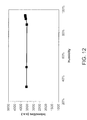
- FIG. 12 is a graph of the maximum emission intensity as a function of humidity for the exemplary yellow-green phosphor [(Sr 0.7 Ba 0.3 ) 0.98 Eu 0.02 ] 2 SiO 3.9 F 0.1 ;
- FIG. 13 relates to fabrication of the novel yellow-green phosphor, and is a graph of the fluorine concentration of a starting material in an exemplary sintered phosphor as a function of the mole percent of fluorine that actually ends up in the phosphor, the fluorine content in the sintered phosphor measured by secondary ion emission spectroscopy (SIMS);
- SIMS secondary ion emission spectroscopy
- FIG. 14 shows the location of the inventive yellow-green phosphors on a CIE diagram, along with an exemplary YAG:Ce phosphor for comparison;
- FIG. 15 is an emission spectrum from an exemplary white LED comprising yellow light from an exemplary (Sr 0.7 Ba 0.3 Eu 0.02 ) 1.95 Si 1.02 O 3.9 F 0.1 phosphor in combination with blue light from a blue LED (used to provide excitation radiation to the exemplary yellow-green phosphor), the excitation wavelength of the blue LED about 450 nm;
- FIG. 16 is an emission spectrum from an exemplary white LED comprising yellow light from the exemplary (Sr 0.7 Ba 0.3 Eu 0.02 ) 1.95 Si 0.02 O 3.9 F 0.1 phosphor in combination with green light from an exemplary green phosphor having the formula (Ba 0.3 Eu 0.02 ) 1.95 Si 1.02 O 3.9 F 0.1 , with blue light from the blue LED as before in FIG. 14 , the excitation radiation from the blue LED again having a wavelength of about 450 nm;
- FIG. 17 is an emission spectrum from an exemplary white LED comprising a blue LED (emitting at a peak wavelength of about 450 nm), the inventive yellow-green phosphor this time adjusted to emit more in the green at about 530 nm, and a red phosphor having the formula CaS:Eu;
- FIG. 18 is a chromaticity diagram showing the positions of an exemplary red, green and yellow phosphor, and the position of the resulting white light created by mixing light from the individual phosphors.
- Embodiments of the present invention will be described in the following order: first, a general description of the novel silicate-based phosphor will be given, particularly with respect to selection of the dopant anion and reasons for its inclusion, and benefits especially in terms of enhanced emission intensity; the alkaline earths present in the phosphor, and the effect their content ratios has on luminescent properties; and the effects that temperature and humidity have on the phosphor. Next, phosphor processing and fabrication methods will be discussed.
- the white light illumination that may be produced using the novel yellow-green phosphor will be disclosed by first discussing the general characteristics of a blue LED, followed by a discussion of other phosphors that may be used in tandom with the novel yellow-green phosphor, such as, in particular, a red phosphor.
- a yellow phosphor having the formula A 2 SiO 4 :Eu 2+ D wherein A is at least one of a divalent metal selected from the group consisting of Sr, Ca, Ba, Mg, Zn, and Cd; and D is a negatively charged ion, present in the phosphor in an amount ranging from about 0.01 to 20 mole percent. There may be more than one of the divalent metal A present in any one phosphor.
- D is a dopant ion selected from the group consisting of F, Cl, Br, and I, but D can also be an element such as N, S, P, As, Sb, and B.
- the silicate-based phosphor is configured to absorb an excitation radiation having a wavelength ranging from about 280 nm to 520 nm, and particularly from wavelengths in the visible portion of that range such as from 430 to 480 nm.
- the present silicate-based phosphor is configured to emit visible light having a wavelength ranging from about 460 nm to 590 nm, and has the formula (Sr 1 ⁇ x ⁇ y Ba x Ca y Eu 0.02 ) 2 SiO 4 ⁇ z D z ; and where 0 ⁇ x ⁇ 1.0, 0 ⁇ y ⁇ 0.8., and 0 ⁇ z ⁇ 0.2.
- an alternative formula is (Sr 1 ⁇ x ⁇ y Ba x Mg y Eu 002 ) 2 SiO 4 ⁇ z D z , where 0 ⁇ x ⁇ 1.0, 0 ⁇ y ⁇ 0.2, and 0 ⁇ z ⁇ 0.2.
- the phosphor may be described by the formula (Sr 1 ⁇ x ⁇ y Ba x M y ) 2 SiO 4 : Eu 2+ D, where 0 ⁇ x ⁇ 1, and M is one or more of Ca, Mg, Zn, Cd.
- the condition 0 ⁇ y ⁇ 0.5 applies when M is Ca; 0 ⁇ y ⁇ 0.1 when M is Mg; and 0 ⁇ y ⁇ 0.5 when M is either Zn or Cd.
- the component D is the element fluorine (F).
- Exemplary phosphors were fabricated according to the present embodiments, and characterized optically in a variety of ways. First, and perhaps most revealing, were tests conducted to evaluate the intensity of the light emitted from the phosphor as a function of wavelength, wherein the test was carried out on a series of phosphor compositions that varied in the content of the D anion. From this data, it is useful to construct a graph of peak emission intensities, as a function of D anion content. Also useful is the construction of a graph of peak emission wavelength, again as a function of D anion content.
- compositions may be fabricated that contain two alkaline earth elements A 1 and A 2 , sometime with an additional (or third) alkaline earth element A 3 , and emission spectra as a function of wavelength may be measured for the different alkaline earths.
- emission spectra as a function of wavelength may be measured for the different alkaline earths.
- the ratio of A 1 /A 2 content may be varied.
- Exemplary data is shown in FIGS. 3-6 .
- the phosphor chosen to illustrate the inventive concept was a yellow-green phosphor of the family [(Sr 1 ⁇ x Ba x ) 0.98 Eu 0.02 ] 2 SiO 4 ⁇ y D y .
- the alkaline earth components (A 1 and A 2 ) in these exemplary compositions are Sr and Ba; that it is an Eu 2+ activated system, and that the D anions chosen for these compositions are F and Cl.
- “D” has been consistently referred to as an anion in this disclosure, it is possible for a cation to be incorporated into the structure. The results of such a composition are shown as well in FIG. 5 , where the inclusion of phosphorus is compared to the results obtained for chlorine and fluorine.
- FIGS. 3-5 The effect of the inclusion of the D anion dopant into the phosphor, where D is fluorine (F) in an exemplary composition, is seen in FIGS. 3-5 .
- the emission spectra was taken of a series of six compositions for the composition [(Sr 0.7 Ba 0.3 ) 0.98 Eu 0.02 ] 2 SiO 4 ⁇ x D x , where the mole percent (mol %) of the fluorine was 0, 3.2, 13.5, 9.0, 16.8, and 19.0, respectively.
- the wavelength of the excitation radiation in this experiment was 450 nm, and so light from this blue LED may be considered to contribute to the subsequently produced white light illumination.
- the results of FIG. 3 show that the emission intensity from this phosphor is significantly increased by doping the compositions with fluorine for concentrations up to about 10 mol %, at which point the intensity begins to fall off as the fluorine concentration is increased further.
- the data from FIG. 3 may be plotted in a slightly different way: the value of the emission intensity at the maximum of each of the peaks may be plotted as a function of fluorine content, as shown for F using the triangle symbols in FIG. 4 .
- the curve in FIG. 3 exhibiting the highest intensity occurred for the composition having a fluorine content of 9 mol %
- the highest point of the F-ion curve in FIG. 4 occurs at a location on the x-axis also at 9 mol %.
- the data in FIG. 4 shows that the fluorine anion is most capable of increasing emission intensity, relative to P and Cl, and in this particular system under study. It is interesting to note that the F and P compositions both peaked at about 9 mol %, whereas the Cl emission intensity was relatively constant over the range 9 to 17 mol %, and may even have shown a slight increase over the 9 to 17 mol % range. It should also be noted that whereas the increase offered by the Cl and P compositions is significant, being about a 40 to 50% in normalized intensity at an optimized concentration, the advantage may not appear to be significant only because of the huge increase of 100% that the F composition displayed.
- FIG. 6 is an example of excitation (absorption) spectra from an exemplary phosphor, tested with an excitation wavelength of about 450 nm, affected by fluorine content in the inventive silicate based phosphors. It showed clearly again that the fluorine dramatically changed the excitation spectra of silicate phosphors, in particular for the wavelength range from about 400 nm to 500 nm. This has a tremendous impact on white LED applications, since the 100 percent increase in excitation intensity at the excitation wavelength 430 to 490 nm of blue LED was achieved with only about 10 percent increase (mole percent) in fluorine concentration.
- FIG. 3 shows a collection of emission spectra of exemplary yellow phosphors varying in fluorine content.
- the wavelength of the excitation radiation used in the experiment was about 450 nm.
- fluorine is added to the phosphor composition in the form of a NH 4 F dopant.
- the present inventors have found that when the NH 4 F dopant amount is very small (about 1%), the position of the peak emission is located at shorter wavelengths, and as more NH 4 F is added, the wavelength increases with dopant amount.
- the luminescence of the Eu doped phosphor is due to the presence of the Eu 2+ in the compound, which undergoes an electronic transition from 4f 6 5d 1 to 4f 7 .
- the wavelength positions of the emission bands depend very much on the host's material or crystal structure, changing from the near-UV to the red region of the spectrum. This dependence is interpreted as due to the crystal field splitting of the 5d level. With increasing crystal field strength, the emission bands shift to longer wavelength.
- the luminescence peak energy of the 5d-4f transition is affected most by crystal parameters denoting electron-electron repulsion; in other word, the distance between Eu 2+ cation and surrounding anions, and the average distance to distant cations and anions.
- the fluorine anion dopant functions predominantly as a flux during sintering processing.
- a flux improves sintering processing in one of two ways: the first is to promote crystal growth with the liquid sintering mechanism, and the second is to absorb and collect the impurities from the crystal grains and improve the phase purity of the sintered materials.
- the host phosphor is (Sr 1 ⁇ x Ba x ) 2 SiO 4 . Both Sr and Ba are very large cations. There may be present smaller cations such as Mg and Ca, which may be considered to be impurities.
- the excitation spectra comparing fluorine containing silicates and non-fluorine containing silicates, as shown in FIG. 6 further confirmed the critical role that fluorine plays in the present embodiments of the present halide containing silicate phosphors.
- the excitation spectra shown in FIG. 6 is obtained by plotting the emission intensity at the wavelength of 540 nm verses an excitation wavelength.
- the excitation intensity is directly related to the absorption and determined by excitation and transmission probability between excitation level and ground level.
- the emission intensity decreases or levels off when the halide concentration increases more than 10 mol % as shown in FIG. 3 .
- This can be explained by Eu emission quenching due to the fact that more defects introduced in associated with the fluorine incorporation into the lattice, the more non-radiation centers will be created to reduce the absorbed energy transferring to Eu 2+ effective emission centers.
- the result in FIG. 3 indicates the maximum intensity increase by fluorine without Eu emission quenching is about 10 mol %.
- the optical properties of the inventive yellow phosphor may be controlled, in addition to the methods discussed above, by adjusting the ratio of the alkaline earth elements contained within the phosphor.
- An exemplary data set that puts this embodiment of the inventive concept into place is illustrated in FIG. 7 .
- FIG. 7 Before turning to FIG. 7 , however, it may be useful to discuss the general effects of typical alkaline earths on the crystal structure of the phosphor, which in turn will affect optical properties, where the alkaline earths under consideration are Sr, Ba, Ca, and Mg.
- Maeda et al. do not teach the benefits of the present dopant ion D in U.S. Patent Application Publication 2004/0104391. Many of the principles pertaining to the alkaline earth content, however, still apply. Maeda et al. teach that when the content of Ba and Ca in a silicate phosphor is very small; in other words, when the content of the alkaline earths in the phosphor is mostly Sr, then the phosphor is likely to assume a monoclinic structure, or a structure comprising a mixture of monoclinic and orthorhombic crystal structures. When Ba is put into the phosphor at higher values than desired with little or no Ca, the crystal field around Eu 2+ ions is weak.
- the crystal structure is again likely to be monoclinic.
- the silicate-based phosphor is likely to have a hexagonal structure. In each of these cases, according to Maeda et al., the phosphor is expected to be greener, and emits light with a low color purity for yellow.
- T. Maeda et al. teach that in order to obtain yellow light from the phosphor, which may be defined as light having a wavelength ranging from about 550 to 600 nm, the desired Ba content in the phosphor should be in a mole fraction from about 0 to 0.3. With regard to the Ca content, the desired condition for obtaining yellow wavelengths lies from about 0 to 0.6, although they conjecture that yellow wavelengths may also be obtained from a compound in which the Ca substitution (for Sr) has a mole fraction of about 0.7. Maeda et al. note that compounds that do not contain any Sr do not emit yellow light.
- the particular interest was to optimize the material configured to emit green to yellow color light by blue excitation.
- the effects of stoichiometric ratio of calcium, strontium and barium on luminescent properties were found in consistent with Maeda et al's results disclosed in their patent.
- the present invention is more focused on the improvements of emission intensity while controlling the emission wavelength in the desired green to yellow region.
- Temperature and humidity effects on the luminescent properties are very important to phosphor-based illumination devices such as white LEDs, based on partial or total conversion of LED emission to other wavelength emissions by the selected phosphor material system.
- the operating temperature range for such phosphor-based radiation devices depends on the specific application requirements. Temperature stable up to 85° C. are generally required for commercial electronic applications. However, temperatures up to 180° C. are desired for high power LED applications. Stability over the entire humidity range of 0 to 100% is required for almost all commercial electronic applications.
- FIGS. 9-11 are plots of maximum luminescent intensity either as a function of temperature, or of wavelength for various temperatures, for an exemplary fluorine containing silicate phosphor (Sr 0.7 Ba 0.3 Eu 0.02 ) 1.95 Si 1.02 O 3.9 F 0.1 .
- This particular phosphor was derived from the series of emission spectra measured at different temperatures shown previously.
- the temperature stability of the phosphor of this invention behaves very similar to that of a commercial YAG phosphor, particularly up to 100° C.
- FIG. 12 shows graph of the stability of the phosphor of this invention for humidity ranging from about 20 to 100%. Without being constrained to any one theory, the inventors believe that while the reason for the 3% increase in emission maximum intensity above 90% humidity is unknown at this time, such a phenomena is reversible when the humidity oscillates between a value of about 90% to 100%.
- Methods of fabricating the novel silicate-based phosphor of the present embodiments are not limited to any one fabrication method, but may, for example, be fabricated in a three step process that includes: 1) blending starting materials, 2) firing the starting material mix, and 3) various processes to be performed on the fired material, including pulverizing and drying.
- the starting materials may comprise various kinds of powders, such as alkaline earth metal compounds, silicon compounds, and europium compounds.
- alkaline earth metal compounds include alkaline earth metal carbonates, nitrates, hydroxides, oxides, oxalates, and halides.
- Examples of silicon compounds include oxides such as silicon oxide and silicon dioxide.
- Examples of europium compounds include europium oxide, europium fluoride, and europium chloride.
- a germanium compound such as germanium oxide may be used as germanium oxide.
- the starting materials are blended in a manner such that the desired final composition is achieved.
- the alkaline-earth, silicon (and/or germanium), and europium compounds are bended in the appropriate ratios, and then fired to achieve the desired composition.
- the blended starting materials are fired in a second step, and to enhance the reactivity of the blended materials (at any or various stages of the firing), a flux may be used.
- the flux may comprise various kinds of halides and boron compounds, examples of which include strontium fluoride, barium fluoride, calcium fluoride, europium fluoride, ammonium fluoride, lithium fluoride, sodium fluoride, potassium fluoride, strontium chloride, barium chloride, calcium chloride, europium chloride, ammonium chloride, lithium chloride, sodium chloride, potassium chloride, and combinations thereof.
- boron-containing flux compounds include boric acid, boric oxide, strontium borate, barium borate, and calcium borate.
- the flux compound is used in amounts where the number of mole percent ranges from between about 0.1 to 3.0, where values may typically range from about 0.1 to 1.0 mole percent, both inclusive.
- Various techniques for mixing the starting materials include using a mortar, mixing with a ball mill, mixing using a V-shaped mixer, mixing using a cross rotary mixer, mixing using a jet mill and mixing using an agitator.
- the starting materials may be either dry mixed or wet mixed, where dry mixing refers to mixing without using a solvent.
- Solvents that may be used in a wet mixing process include water or an organic solvent, where the organic solvent may be either methanol or ethanol.
- the mix of starting materials may be fired by numerous techniques known in the art.
- a heater such as an electric furnace or gas furnace may be used for the firing.
- the heater is not limited to any particular type, as long as the starting material mix is fired at the desired temperature for the desired length of time.
- firing temperatures may range from about 800 to 1600° C.
- the firing time may range from about 10 minutes to 1000 hours.
- the firing atmosphere may be selected from among air, a low-pressure atmosphere, a vacuum, an inert-gas atmosphere, a nitrogen atmosphere, an oxygen atmosphere, an oxidizing atmosphere, and/or a reducing atmosphere. Since Eu 2+ ions need to be included in the phosphor at some stage of the firing, it is desired in some embodiments to provide a reducing atmosphere using a mixed gas of nitrogen and hydrogen.
- Exemplary methods of preparing the present phosphors include a sol-gel method and a solid reaction method.
- the sol-gel method may be used to produce powder phosphors.
- a typical procedure comprised the steps of:
- the solid reaction method was also used for silicate-based phosphors.
- the steps of a typical procedure used for the solid reaction method are as following:
- the concentration of fluorine in the sintered phosphor [(Sr 1 ⁇ x Ba x ) 0.98 Eu 0.02 ] 2 SiO 4 ⁇ y F y was measured using secondary ion emission spectroscopy (SIMS), and the results are shown in FIG. 13 .
- the fluorine was added to the phosphor as NH 4 F.
- the results show that for a mol % of fluorine of about 20 mol % in the starting material, the sintered phosphor ends up with about 10 mol %.
- the content of fluorine in the raw material is about 75 mol %
- the content of fluorine in the sintered phosphor is about 18 mol %.
- the white light illumination that may be produced using the inventive, novel yellow-green phosphor will be discussed in this final portion of the disclosure.
- the first section of this final portion will begin with a description of exemplary blue LED's that may be used to excite the inventive yellow-green phosphor. That the present yellow-green phosphors are capable of absorbing, and be excited by, light over a large range of wavelengths, including the blue portion of the visible, is demonstrated by the excitation (absorption) spectra of FIG. 6 .
- a generalized description of the CIE diagram will be provided, along with the location of the inventive yellow-green phosphor on the diagram, as shown in FIG. 14 . According to the general scheme of FIG.
- light from the inventive yellow-green phosphor may be combined with light from the blue LED to make white illumination; the results of such an experiment are shown in an emission intensity versus wavelength plot for this system in FIG. 15 .
- the color rendering of the white light may be adjusted with the inclusion of other phosphors in the system, as exemplified by the spectrum of FIG. 16 .
- the inventive phosphor may be adjusted to emit more in the green, and combined with a red phosphor to make up the phosphor system, which together with the blue light from the blue LED produces the spectrum in FIG. 17 .
- the CIE diagram of the resulting white light is shown in FIG. 18 .
- the blue light emitting LED emits light having a main emission peak in the wavelength range greater than or equal to about 400 nm, and less than or equal to about 520 nm.
- This light serves two purposes: 1) it provides the excitation radiation to the phosphor system, and 2) it provides blue light which, when combined with the light emitted from the phosphor system, makes up the white light of the white light illumination.
- the blue LED emits light greater than or equal to about 420 nm, and less than or equal to about 500 nm. In yet another embodiment, the blue LED emits light greater than or equal to about 430 and less than or equal to about 480 nm. The blue LED wavelength may be 450 nm.
- the blue light emitting device of the present embodiments is herein described generically as a “blue LED,” but it will be understood by those skilled in the art that the blue light emitting device may be at least one of (wherein it is contemplated to have several operating simultaneously) a blue light emitting diode, a laser diode, a surface emitting laser diode, a resonant cavity light emitting diode, an inorganic electroluminescence device and an organic electroluminescence device. If the blue light emitting device is an inorganic device, it may be a semiconductor selected from the group consisting of a gallium nitride based compound semiconductor, a zinc selenide semiconductor and a zinc oxide semiconductor.
- FIG. 6 is an excitation spectrum of the present yellow-green phosphors, showing that these novel phosphors are capable of absorbing radiating over a range of about 280 to 520 nm, and relevant to the present embodiments, over a range of about 400 to 520 nm.
- the novel yellow-green phosphors absorb radiation (in other words, are capable of being excited by radiation) ranging from 430 to 480 nm.
- the phosphor absorbs radiation having a wavelength of about 450 nm.
- White light illumination is constructed by mixing various or several monochromatic colors from the visible portion of the electromagnetic spectrum, the visible portion of the spectrum comprising roughly 400 to 700 nm.
- the human eye is most sensitive to a region between about 475 and 650 nm.
- To create white light from either a system of LED's, or a system of phosphors pumped by a short wavelength LED it is necessary to mix light from at least two complementary sources in the proper intensity ratio.
- the results of the color mixing are commonly displayed in a CIE “chromaticity diagram,” where monochromatic colors are located on the periphery of the diagram, and white at the center.
- the objective is to blend colors such that the resulting light may be mapped to coordinates at the center of the diagram.
- color temperature Another term of art is “color temperature,” which is used to describe the spectral properties of white light illumination. The term does not have any physical meaning for “white light” LED's, but it is used in the art to relate the color coordinates of the white light to the color coordinates achieved by a black-body source. High color temperature LED's versus low color temperature LED's are shown at www.korry.com.
- Chromaticity (color coordinates on a CIE chromaticity diagram) has been described by Srivastava et al. in U.S. Pat. No. 6,621,211.
- the chromaticity of the prior art blue LED-YAG:Ce phosphor white light illumination system described above are located adjacent to the so-called “black body locus,” or BBL, between the temperatures of 6000 and 8000 K.
- BBL black body locus
- White light illumination systems that display chromaticity coordinates adjacent to the BBL obey Planck's equation (described at column 1, lines 60-65 of that patent), and are desirable because such systems yield white light which is pleasing to a human observer.
- the color rendering index is a relative measurement of how an illumination system compares to that of a black body radiator.
- the CRI is equal to 100 if the color coordinates of a set of test colors being illuminated by the white light illumination system are the same as the coordinates generated by the same set of test colors being irradiated by a black body radiator.
- the yellow to yellow-green color of these exemplary phosphors may advantageously be mixed with blue light from the blue LED described above (wherein the blue light has a wavelength ranging from about 400 to 520 nm in one embodiment, and 430 to 480 nm in another embodiment) to construct the white light illumination desired for a multiplicity of applications.
- FIG. 15 shows the results of mixing light from a blue LED with an exemplary yellow phosphor, in this case the yellow phosphor having the formula (Sr 0.7 Ba 0.3 Eu 0.02 ) 1.95 Si 1.02 O 3.9 F 0.1 .
- the present yellow-green phosphor may be used in conjunction with other phosphors, as part of a phosphor system, whereupon the light emitted from each of the phosphors of the phosphor system may be combined with the blue light from the blue LED to construct white light with alternative color temperatures and color renderings.
- green, orange and/or red phosphors disclosed previously in the prior art may be combined with the present yellow-green phosphor.
- U.S. Pat. No. 6,649,946 to Bogner et al. disclosed yellow to red phosphors based on alkaline earth silicon nitride materials as host lattices, where the phosphors may be excited by a blue LED emitting at 450 nm.
- M is at least one of an alkaline earth metal chosen from the group Ca, Sr, and Ba
- red to yellow phosphors were disclosed with a blue light emitting primary source together with one or more red and green phosphors.
- the objective of such a material was to improve the red color rendition R9 (adjust the color rendering to red-shift), as well as providing a light source with an improved overall color rendition Ra.
- supplementary phosphors including red phosphors
- red phosphors that may be used with the present yellow-green phosphor
- U.S. Patent Application Publication 2003/0006702 to Mueller-Mach which disclosed a light emitting device having a (supplemental) fluorescent material that receives primary light from a blue LED having a peak wavelength of 470 nm, the supplemental fluorescent material radiating light in the red spectral region of the visible light spectrum.
- the supplementary fluorescent material is used in conjunction with a main fluorescent material to increase the red color component of the composite output light, thus improving the white output light color rendering.
- the main fluorescent material is a Ce activated and Gd doped yttrium aluminum garnet (YAG), while the supplementary fluorescent material is produced by doping the YAG main fluorescent material with Pr.
- the supplementary fluorescent material is a Eu activated SrS phosphor.
- the red phosphor may be, for example, (SrBaCa) 2 Si 5 N 8 : Eu 2+ .
- the main fluorescent material (YAG phosphor) has the property of emitting yellow light in response to the primary light from the blue LED.
- the supplementary fluorescent material adds red light to the blue light from the blue LED and the yellow light from the main fluorescent material.
- U.S. Pat. No. 6,504,179 to Ellens et al. disclose a white LED based on mixing blue-yellow-green (BYG) colors.
- the yellow emitting phosphor is a Ce-activated garnet of the rare earths Y, Tb, Gd, Lu, and/or La, where a combination of Y and Tb was preferred.
- the yellow phosphor was a terbium-aluminum garnet (TbAG) doped with cerium (Tb 3 Al 5 O 12 —Ce).
- the green emitting phosphor comprised a CaMg chlorosilicate framework doped with Eu (CSEu), and possibly including quantities of further dopants such as Mn.
- Alternative green phosphors were SrAl 2 O 4 :Eu and Sr 4 Al 14 O 25 :Eu 2+ .
- the novel yellow-green phosphor may be used in a combination of green and yellow phosphors (Tb 3 Al 5 O 12 —Ce).
- the formula for the orange phosphor could be written (A 1 ⁇ x ⁇ y Eu x Mn y ) 2 P 2 O 7 where 0 ⁇ x ⁇ 0.2, and 0 ⁇ y ⁇ 0.2.
- the second phosphor emits blue-green light having a peak emission wavelength between 495 and 550 nm, and is a divalent europium activated alkaline earth silicate phosphor ASiO:Eu 2+ , where A comprised at least one of Ba, Ca, Sr, or Mb.
- the third phosphor emitted blue light having a peak emission wavelength between 420 and 480 nm, and comprised either of the two commercially available phosphors “SECA,” D 5 (PO 4 ) 3 Cl:Eu 2+ , where D was at least one of Sr, Ba, Ca, or Mg, or “BAM,” which may be written as AMg 2 Al 16 O 27 , where A comprised at least one of Ba, Ca, or Sr, or BaMgAl 10 O 17 :Eu 2+ .
- the optional fourth phosphor emits red light having a peak emission wavelength between 620 and 670 nm, and it may comprise a magnesium fluorogermanate phosphor MgO*MgF*GeO:Mn 4+ .
- a white illumination device can be constructed using a GaN based blue LED having a emission peak wavelength ranging about 430 nm to 480 nm, in combination with the inventive yellow phosphor with an emission peak wavelength ranging from about 540 nm to 580 nm.
- FIG. 15 is a combination spectra measured from a white illumination device, which consists of a blue LED and the inventive yellow phosphor layer. The conversion efficiency and the amount of the phosphor used in the device directly determines the color coordination of the white illumination devices in CIE diagram. In this case, a color temperature of about 5,000 to 10,000 K with a color coordination where X ranges from 0.25 to 0.40 and Y ranges from 0.25 to 0.40 can be achieved by combining light from the blue LED with light from the inventive yellow phosphor.
- a white illumination device may be constructed using a GaN based blue LED having an emission peak wavelength ranging from about 430 nm to 480 nm; the inventive yellow phosphor has an emission peak wavelength ranging from about 540 nm to 580 nm; and an inventive green phosphor having an emission peak wavelength ranging from about 500 nm to 520 nm.
- the color rendering of the resulting white light has been improved with this solution of mixing green and yellow phosphors.
- FIG. 16 is a combination spectra measured from a white illumination device comprising the light from a blue LED, and the light from a mixture of the inventive yellow and green phosphors.
- the conversion efficiency and the amounts of the phosphors used in the device directly determine the color coordination of the white illumination devices in CIE diagram.
- a color temperature of 5,000 to 7,000 K with a color rendering greater than 80 was achieved by combining light from the blue LED with light from a mixture of the inventive yellow and green phosphors.
- a white illumination device may be constructed by using a GaN based blue LED having an emission peak wavelength ranging from about 430 nm to 480 nm; the inventive green phosphor having an emission peak wavelength ranging from about 530 nm to 540 nm; and a commercially available red phosphor such as Eu doped CaS having an emission peak wavelength ranging from 600 nm to 670 nm.
- the color temperature may be adjusted to 3,000 K, and color rendering may be enhanced to a value greater than about 90 using the presently disclosed green and red phosphors.
- FIG. 17 is a combination spectra measured from a white illumination device comprising a blue LED and the mixture of the inventive green and CaS:Eu phosphors.
- the conversion efficiency and amount of the phosphor used in the device directly determines the color coordination of the white illumination devices in CIE diagram.
- the color temperature of 2,500 to 4,000 K with color rendering greater than 85 can be achieved by combining light from the blue LED with light from a mixture of the inventive red and green phosphor system.
- FIG. 18 shows the position of the resultant white light illumination on a CIE diagram.
- the present yellow-green silicates may be advantageously combined with the newer, nitride-based “deep-red” phosphors in white LED systems.
- the resultant white light has better color rendering characteristics, to name one advantage.
- nitride-based silicates or nitridosilicates were based on nitrides of silicon, and hence may be generically referred to as “nitride-based” silicates or nitridosilicates. Newer versions have included aluminum to provide the compounds “nitridoaluminosilicate nitrides.” The inclusion of oxygen into these crystals, deliberate or otherwise, may also give to the desired deep red phosphors, even though similar compounds known as “SiAlONs” in some cases are sources of green and yellow-green illumination. When oxygen substitutes for nitrogen the resulting compound is an “oxynitrides.”
- the phosphor-generated light may be used to produce the white light from a so-called “white LED.”
- the phosphor-generated light comprises both a yellow-green light from one of the silicate-based yellow-green phosphors described above, and one of the newer “deep red” type phosphors generally having a nitride host structure, such a structure optionally having aluminum (Al) partially replacing silicon (Si) in one embodiment, and oxygen (O) partially replacing nitrogen (N) in another.
- Nitrides and oxynitrides, each with and without aluminum, are contemplated by the present embodiments.
- a blue emitting LED such as one providing excitation radiation ranging from about 400 to 480 nm, is deemed to be particularly suitable for exciting both the yellow-green and the red phosphors.
- Previously known white light generating systems used a blue LED in conjunction with a yellow emitting, cerium-doped, yttrium aluminum garnet known as “YAG,” having the formula Y 3 Al 5 O 12 :Ce 3+ .
- YAG cerium-doped, yttrium aluminum garnet
- CCTs correlated temperatures
- CRIs color rendering indexes
- One method of achieving this flexibility of design in blue LED-based devices is to provide a wider separation of the yellow-green and red phosphors relative to one another in CIE space, where these two apexes of a triangle formed with the light from the blue LED create a rich diversity of components for white light generation.
- the position of the 5d excitation bands of the Eu 2+ ions in these compounds at low energies is attributable to the influence of the highly covalent nature of the europium on an alkaline earth metal site with nitrogen atoms, leading to a large crystal field splitting, as well, also due to the presence of nitrogen.
- the covalency of the Eu—N bond and the resultant crystal field strength around the Eu 2+ ions is similar in each of the members of this series (e.g., Ca, Sr, and Ba-based), despite the fact there are two M sites with different symmetries.
- white LEDs Of particular importance to white LEDs is the fact these compounds have efficient excitation in the same spectral region (400 to 470 nm), matching the radiative blue light from an InGaN-based LED, which emits around 465 nm. Their broad-band emissions are due to a 4f 6 5d 1 ⁇ 4f 7 transition within the Eu 2+ ion, with the Ca compound emitting at wavelengths ranging from about 605-615 nm, Sr at 609-680 nm, and Ba at 570-680 nm.
- the emission band of Eu 2+ successively shifts from orange when M is Sr, and yellow when M is Ba at low Eu concentrations, to red (up to 680 nm) for high concentrations of Eu.
- the excitation spectra are not substantially dependent on the type of alkaline earth, but the position of the emission bands are.
- the shift in the emission band with the nature of the alkaline earth is due to a difference in the Stokes shift for each of the members, where the Stokes shift gradually increases with the sequence Ca>Sr>Ba, and this trend is predictable if one observes that the relaxation of the 4f 6 5d 1 state becomes less restricted when the size of the alkaline-earth ion decreases. Further, the Stokes shift increases for as the Eu concentration is increased in all cases.
- Aluminonitridosilicates may be derived from nitridosilicates by substitutions of aluminum for silicon.
- a new red phosphor having the formula Ca 2 AlSiN 3 has been described by K. Uheda et al. in “Luminescence properties of a red phosphor, CaASiN 3 :Eu 2+ , for white light-emitting diodes,” in Electrochemical and solid - state letters, 9 (4) (2006), pages H22-H25.
- the crystal structure of the CaAlSiN 3 :Eu 2+ was found to be orthorhombic with a Cmc21 space group, where the unit cell volume expanded linearly with an increase in Eu concentration up to at least 20 mole percent.
- the structure is made up of tetrahedra of [SiN 4 ] and [AlN 4 ] forming corner sharing six-member rings; rings are combined to form sheets, of which there are two types.
- the overall structure is made up of overlaying sheets rotated 180 degrees to one another, forming a rigid three-dimensional framework, with the Ca 2+ ions accommodated in cavities in the overlaid planes, and where the Eu 2+ ions substitute for the Ca 2+ ions.
- Two thirds of the N atoms are coordinated with three Si atoms, and the remaining N atoms are coordinated with two Si atoms.
- CaSiN 2 :Eu 2+ This is to be contrasted with the nitridosilicate phosphor CaSiN 2 :Eu 2+ described earlier, where all the N atoms are coordinated with two Si atoms.
- CaAlSiN 3 :Eu 2+ has a more rigid structure than CaSiN 2 :Eu 2+ .
- the excitation spectra of the aluminonitridosilicate CaAlSiN 3 :Eu 2+ shows a broad excitation band that extends to the visible region.
- This feature means that CaAlSiN 3 :Eu 2+ is also suitable for excitation by a blue or near-UV LED.
- the luminescence of this nitridoaluminosilicate shows a single band typical of a 5d-4f transition of Eu 2+ .
- the phosphor Under 405 nm excitation, the phosphor exhibits a peak emission at about 660 nm, and the emission looks deep red. With an increase in Eu concentration, the emission peak shifts toward longer wavelengths, and quantum output reaches a maximum at about 1.6 mole percent. The quantum output is about 1.5 times that of the YAG class of aluminates, (Y,Gd) 3 (Al,Ga) 5 O 12 :Ce 3+ , under 460 nm excitation.
- US 2006/0255710 to Mueller-Mach et al. teach a class of phosphor materials based on rare earth metal-activated luminescence of an aluminum-substituted oxonitridosilicate.
- the phosphor comprises a host lattice where the main components are silicon, aluminum, nitrogen, and oxygen.
- the host lattice has a structure comprising stacks of layers of [(Al,Si) 2 N 6/3 (N,O) 2/2 ], where the silicon and aluminum are surrounded by oxygen and nitrogen in a tetrahedral fashion.
- the phosphor described by Mueller-Mach et al. conforms to the general formula (Ca 1 ⁇ x ⁇ y ⁇ z Sr x Ba y Mg z ) 1 ⁇ n (Al 1 ⁇ a+b B z )Si 1 ⁇ b N 3 ⁇ b O b :RE n , where 0 ⁇ x ⁇ 1; 0 ⁇ y ⁇ 1; 0 ⁇ z ⁇ 1; 0 ⁇ a ⁇ 1; 0 ⁇ b ⁇ 1; and 0.002 ⁇ n ⁇ 0.2 and RE is selected from Eu 2+ and Ce 3+ .
- a similar Ba-based phosphor having the formula Ca 0.95 Ba 0.05 AlSi(N,O) 3 :Eu(2%) has x and y coordinates 0.676 and 0.323, respectively.
- the emission peak of the Sr-based phosphor is at 657 nm; that of the Ba-based phosphor is 658 nm.
- x and y are 0.667 and 0.323, respectively, and the peak emission is at 650 nm.
- a higher concentration of B as in the formula CaAl 0.95 B 0.05 Si(N,O) 3 :Eu(2%), has x and y values of 0.663 and 0.336, respectively, with a peak emission at 654 nm.
- Mueller-Mach et al. point out advantages of using these oxonitridoaluminosilicates in conjunction with other phosphors in a white LED system.
- the advantages include 1) these red emitting oxonitridoaluminosilicates do not degrade when used in high humidity environments, 2) they are stable when driven at high current, or operated at high temperature, 3) they may be configured to emit a deeper red light (longer wavelength) relative to previous red phosphors, and 4) they may be readily combined with other phosphors, such as the present yellow-green silicates.
- the present yellow-green silicates may be combined with a red phosphor selected from the group consisting of a nitridosilicate, an oxynitridosilicate, a nitridoaluminosilicate, and an oxynitridoaluminosilicate.
- a red phosphor selected from the group consisting of a nitridosilicate, an oxynitridosilicate, a nitridoaluminosilicate, and an oxynitridoaluminosilicate.
- M 2 Si 5 N 8 Eu where M is Ca, Sr, and Ba;
Abstract
Description
-
- (1) In (Sr1−xBax)2SiO4 phosphor materials, the emission peak wavelength changes from green at 500 nm for x=1 (100% Ba) to yellow at 580 nm for x=0 (100% Sr) as shown in
FIG. 7 . The conversion efficiency from the same light source at 450 nm shows a continuous increase when the Ba increases from 0 to about 90%. The peak emission wavelength of 545 nm obtained when Ba to Sr ratio is 0.3 to 0.7 is close to the pure YAG:Ce peak emission wavelength as compared inFIG. 7 . - (2) Calcium substitution of barium or strontium in the Sr—Ba based silicate phosphor system will in general reduce the emission intensity, even they can be favored for moving the emission to longer wavelength when calcium substitution is less than 40%.
- (3) Magnesium substitution of barium or strontium in the Sr—Ba based silicate phosphors will in general reduce the emission intensity and move the emission to shorter wavelengths. However, the small amount of magnesium substitution of barium or strontium (<10%) will enhance the emission intensity and move the emission to longer wavelengths. For example, five percent of substitution of barium by magnesium in (Sr0.9Ba0.1)2SiO4 will increase the emission intensity and move to a slightly longer wavelength, as shown in
FIG. 7 for the curve labeled [(Sr0.9Ba0.075Mg0.025)0.98Eu0.02]2SiO3.9F0.1. - (4) To match or improve upon a YAG emission spectrum, it may be necessary in some embodiments of the present invention to mix the inventive silicate phosphors.
FIG. 8 shows that a substantially identical CIE color of YAG can be prepared by mixing 40% [(Sr0.7Ba0.3)0.98Eu0.02]2SiO3.9F0.1 and 60% [(Sr0.9Ba0.05Mg0.05)0.98Eu0.02]2SiO3.9F0.1. The total brightness of the mixture is estimated to be nearly 90% as bright as the YAG composition.
Effects of Temperature and Humidity on the Phosphor
- (1) In (Sr1−xBax)2SiO4 phosphor materials, the emission peak wavelength changes from green at 500 nm for x=1 (100% Ba) to yellow at 580 nm for x=0 (100% Sr) as shown in
- 1. a) Dissolving certain amounts of alkaline earth nitrates (Mg, Ca, Sr, Ba), and Eu2O3 and/or BaF2 or other alkaline earth metal halides in dilute nitric acid; and b) Dissolving corresponding amount of silica gel in de-ionized water to prepare a second solution.
- 2. After the solids of the two solutions of steps 1a) and 1b) above were totally dissolved, the two solutions were mixed and stirred for two hours. Ammonia was then used to generate a gel in the mixture solution. Following formation of the gel, the pH was adjusted to about 9.0, and the gelled solution stirred continuously at about 60° C. for 3 hours.
- 3. After drying the gelled solution by evaporation, the resulted dry gel was decomposed at 500 to 700° C. for about 60 minutes to decompose and acquire oxides.
- 4. After cooling and grinding with certain amount of NH4F or other ammonia halides when alkaline earth metal halides are not used in step 1a), the powder was sintered in a reduced atmosphere for about 6 to 10 hours. The calcining/sintering temperature ranged from about 1200 to 1400° C.
- 1. Desired amounts of alkaline earth oxides or carbonates (Mg, Ca, Sr, Ba), dopants of Eu2O3 and/or BaF2 or other alkaline earth metal halides, corresponding SiO2 and/or NH4F or other ammonia halides were wet mixed with a ball mill.
- 1. After drying and grinding, the resulting powder was calcined/sintered in a reduced atmosphere for about 6 to 10 hours. The calcining/sintering temperature ranged from 1200 to 1400° C.
Claims (2)
Priority Applications (3)
| Application Number | Priority Date | Filing Date | Title |
|---|---|---|---|
| US11/963,994 US8017035B2 (en) | 2004-08-04 | 2007-12-24 | Silicate-based yellow-green phosphors |
| PCT/US2008/087822 WO2009082714A1 (en) | 2007-12-24 | 2008-12-19 | Novel silicate-based yellow-green phosphors |
| TW097150485A TW200948932A (en) | 2007-12-24 | 2008-12-24 | Novel silicate-based yellow-green phosphors |
Applications Claiming Priority (3)
| Application Number | Priority Date | Filing Date | Title |
|---|---|---|---|
| US10/912,741 US7267787B2 (en) | 2004-08-04 | 2004-08-04 | Phosphor systems for a white light emitting diode (LED) |
| US10/948,764 US7311858B2 (en) | 2004-08-04 | 2004-09-22 | Silicate-based yellow-green phosphors |
| US11/963,994 US8017035B2 (en) | 2004-08-04 | 2007-12-24 | Silicate-based yellow-green phosphors |
Related Parent Applications (2)
| Application Number | Title | Priority Date | Filing Date |
|---|---|---|---|
| US10/948,764 Continuation US7311858B2 (en) | 2004-08-04 | 2004-09-22 | Silicate-based yellow-green phosphors |
| US10/948,764 Continuation-In-Part US7311858B2 (en) | 2004-08-04 | 2004-09-22 | Silicate-based yellow-green phosphors |
Publications (2)
| Publication Number | Publication Date |
|---|---|
| US20080116786A1 US20080116786A1 (en) | 2008-05-22 |
| US8017035B2 true US8017035B2 (en) | 2011-09-13 |
Family
ID=40801799
Family Applications (1)
| Application Number | Title | Priority Date | Filing Date |
|---|---|---|---|
| US11/963,994 Expired - Fee Related US8017035B2 (en) | 2004-08-04 | 2007-12-24 | Silicate-based yellow-green phosphors |
Country Status (3)
| Country | Link |
|---|---|
| US (1) | US8017035B2 (en) |
| TW (1) | TW200948932A (en) |
| WO (1) | WO2009082714A1 (en) |
Cited By (4)
| Publication number | Priority date | Publication date | Assignee | Title |
|---|---|---|---|---|
| US20120313126A1 (en) * | 2011-06-08 | 2012-12-13 | Advanced Optoelectronic Technology, Inc. | Led package |
| US8729791B1 (en) | 2012-12-13 | 2014-05-20 | Industrial Technology Research Institute | Phosphor, and light emitting device employing the same |
| TWI456803B (en) * | 2012-11-02 | 2014-10-11 | Ind Tech Res Inst | Illumination device |
| US10745616B2 (en) | 2015-03-24 | 2020-08-18 | Merck Patent Gmbh | Phosphors and phosphor-converted LEDs |
Families Citing this family (27)
| Publication number | Priority date | Publication date | Assignee | Title |
|---|---|---|---|---|
| US8475683B2 (en) | 2006-10-20 | 2013-07-02 | Intematix Corporation | Yellow-green to yellow-emitting phosphors based on halogenated-aluminates |
| US8274215B2 (en) | 2008-12-15 | 2012-09-25 | Intematix Corporation | Nitride-based, red-emitting phosphors |
| JP2010090231A (en) * | 2008-10-07 | 2010-04-22 | Canon Inc | Image display |
| CN101475804B (en) * | 2008-12-02 | 2013-05-29 | 罗维鸿 | Orthosilicate green phosphor for light emitting diode and preparation thereof |
| KR20100070731A (en) * | 2008-12-18 | 2010-06-28 | 삼성전자주식회사 | Halosilicate phosphors and white light emitting devices including same |
| DE102009032711A1 (en) * | 2009-07-11 | 2011-01-20 | Merck Patent Gmbh | Co-doped silicooxynitrides |
| US8592829B2 (en) * | 2009-08-17 | 2013-11-26 | Osram Sylvania Inc. | Phosphor blend for an LED light source and LED light source incorporating same |
| US9293644B2 (en) | 2009-09-18 | 2016-03-22 | Soraa, Inc. | Power light emitting diode and method with uniform current density operation |
| US8933644B2 (en) | 2009-09-18 | 2015-01-13 | Soraa, Inc. | LED lamps with improved quality of light |
| US8502465B2 (en) * | 2009-09-18 | 2013-08-06 | Soraa, Inc. | Power light emitting diode and method with current density operation |
| US9583678B2 (en) | 2009-09-18 | 2017-02-28 | Soraa, Inc. | High-performance LED fabrication |
| KR101414948B1 (en) * | 2010-05-25 | 2014-07-04 | 도호쿠 다이가쿠 | PROCESS FOR PRODUCTION OF Eu-ACTIVATED ALKALINE EARTH METAL SILICATE PHOSPHOR |
| US8831060B2 (en) * | 2010-06-22 | 2014-09-09 | Koninklijke Philips N.V. | Laser |
| WO2012003854A1 (en) * | 2010-07-09 | 2012-01-12 | Giesecke & Devrient Gmbh | Security feature |
| CN102337123B (en) * | 2010-07-20 | 2013-11-27 | 海洋王照明科技股份有限公司 | Silicate luminescent material and preparation method thereof |
| WO2013074158A1 (en) * | 2011-11-16 | 2013-05-23 | Intematix Corporation | Green and yellow aluminate phosphors |
| US8663502B2 (en) | 2011-12-30 | 2014-03-04 | Intematix Corporation | Red-emitting nitride-based phosphors |
| WO2013102222A1 (en) | 2011-12-30 | 2013-07-04 | Intematix Corporation | Nitride phosphors with interstitial cations for charge balance |
| CN102537739B (en) * | 2012-01-08 | 2013-10-30 | 浙江新天天光电科技有限公司 | Yellow LED light source component |
| US8597545B1 (en) | 2012-07-18 | 2013-12-03 | Intematix Corporation | Red-emitting nitride-based calcium-stabilized phosphors |
| US9761763B2 (en) | 2012-12-21 | 2017-09-12 | Soraa, Inc. | Dense-luminescent-materials-coated violet LEDs |
| US9410664B2 (en) | 2013-08-29 | 2016-08-09 | Soraa, Inc. | Circadian friendly LED light source |
| US10066160B2 (en) | 2015-05-01 | 2018-09-04 | Intematix Corporation | Solid-state white light generating lighting arrangements including photoluminescence wavelength conversion components |
| EP3893286B1 (en) * | 2016-05-26 | 2023-01-18 | Nichia Corporation | Light emitting device |
| CN110713827B (en) * | 2019-10-31 | 2022-05-06 | 云南民族大学 | Mn-doped steel wire4+Hexafluoro compound red fluorescent powder and synthetic method thereof |
| CN112410033B (en) * | 2020-10-20 | 2023-06-30 | 青岛中科芯成照明技术有限公司 | Fluorescent material, fluorescent film material and high-heat-dissipation fluorescent film |
| CN116376539B (en) * | 2023-02-28 | 2024-03-08 | 江门市科恒实业股份有限公司 | LED green powder and preparation method thereof |
Citations (24)
| Publication number | Priority date | Publication date | Assignee | Title |
|---|---|---|---|---|
| US3505240A (en) | 1966-12-30 | 1970-04-07 | Sylvania Electric Prod | Phosphors and their preparation |
| US5998925A (en) | 1996-07-29 | 1999-12-07 | Nichia Kagaku Kogyo Kabushiki Kaisha | Light emitting device having a nitride compound semiconductor and a phosphor containing a garnet fluorescent material |
| EP0972815A1 (en) | 1997-03-26 | 2000-01-19 | Zhiguo Xiao | Silicate phosphor with a long afterglow and manufacturing method thereof |
| US6501100B1 (en) | 2000-05-15 | 2002-12-31 | General Electric Company | White light emitting phosphor blend for LED devices |
| US6504179B1 (en) | 2000-05-29 | 2003-01-07 | Patent-Treuhand-Gesellschaft Fur Elektrische Gluhlampen Mbh | Led-based white-emitting illumination unit |
| US20030006702A1 (en) | 1999-02-18 | 2003-01-09 | Lumileds Lighting, U.S., Llc | Red-deficiency compensating phosphor light emitting device |
| WO2003021691A1 (en) | 2001-09-03 | 2003-03-13 | Matsushita Electric Industrial Co., Ltd. | Semiconductor light emitting device, light emitting apparatus and production method for semiconductor light emitting device |
| US6555958B1 (en) | 2000-05-15 | 2003-04-29 | General Electric Company | Phosphor for down converting ultraviolet light of LEDs to blue-green light |
| US6621211B1 (en) | 2000-05-15 | 2003-09-16 | General Electric Company | White light emitting phosphor blends for LED devices |
| US6649946B2 (en) | 1999-11-30 | 2003-11-18 | Osram Opto Semiconductors Gmbh | Light source using a yellow-to-red-emitting phosphor |
| US20030227007A1 (en) | 2002-04-15 | 2003-12-11 | Sumitomo Chemical Company, Limited | Phosphor for white LED and a white LED |
| US6765237B1 (en) | 2003-01-15 | 2004-07-20 | Gelcore, Llc | White light emitting device based on UV LED and phosphor blend |
| US6982045B2 (en) | 2003-05-17 | 2006-01-03 | Phosphortech Corporation | Light emitting device having silicate fluorescent phosphor |
| US20060028122A1 (en) | 2004-08-04 | 2006-02-09 | Intematix Corporation | Novel silicate-based yellow-green phosphors |
| US7026755B2 (en) | 2003-08-07 | 2006-04-11 | General Electric Company | Deep red phosphor for general illumination applications |
| US20060197432A1 (en) | 2005-03-01 | 2006-09-07 | Dowa Mining Co., Ltd. | Phosphor mixture and light emitting device |
| US20060208262A1 (en) | 2005-03-18 | 2006-09-21 | Fujikura Ltd., Independent Administrative Institution | Light emitting device and illumination apparatus |
| US20060255710A1 (en) | 2005-03-09 | 2006-11-16 | Regina Mueller-Mach | Illumination system comprising a radiation source and a fluorescent material |
| US20060261309A1 (en) | 2004-08-04 | 2006-11-23 | Intematix Corporation | Two-phase silicate-based yellow phosphor |
| US20070037834A1 (en) | 2002-06-07 | 2007-02-15 | Hitoshi Arai | Bicyclic pyrimidine derivatives |
| US7229573B2 (en) | 2004-04-20 | 2007-06-12 | Gelcore, Llc | Ce3+ and Eu2+ doped phosphors for light generation |
| US7250715B2 (en) | 2004-02-23 | 2007-07-31 | Philips Lumileds Lighting Company, Llc | Wavelength converted semiconductor light emitting devices |
| US7252787B2 (en) | 2003-10-29 | 2007-08-07 | General Electric Company | Garnet phosphor materials having enhanced spectral characteristics |
| US7262439B2 (en) | 2005-11-22 | 2007-08-28 | Lumination Llc | Charge compensated nitride phosphors for use in lighting applications |
-
2007
- 2007-12-24 US US11/963,994 patent/US8017035B2/en not_active Expired - Fee Related
-
2008
- 2008-12-19 WO PCT/US2008/087822 patent/WO2009082714A1/en active Application Filing
- 2008-12-24 TW TW097150485A patent/TW200948932A/en unknown
Patent Citations (29)
| Publication number | Priority date | Publication date | Assignee | Title |
|---|---|---|---|---|
| US3505240A (en) | 1966-12-30 | 1970-04-07 | Sylvania Electric Prod | Phosphors and their preparation |
| US5998925A (en) | 1996-07-29 | 1999-12-07 | Nichia Kagaku Kogyo Kabushiki Kaisha | Light emitting device having a nitride compound semiconductor and a phosphor containing a garnet fluorescent material |
| EP0972815A1 (en) | 1997-03-26 | 2000-01-19 | Zhiguo Xiao | Silicate phosphor with a long afterglow and manufacturing method thereof |
| US6093346A (en) | 1997-03-26 | 2000-07-25 | Xiao; Zhiguo | Long afterglow silicate luminescent material and its manufacturing method |
| US20030006702A1 (en) | 1999-02-18 | 2003-01-09 | Lumileds Lighting, U.S., Llc | Red-deficiency compensating phosphor light emitting device |
| US6649946B2 (en) | 1999-11-30 | 2003-11-18 | Osram Opto Semiconductors Gmbh | Light source using a yellow-to-red-emitting phosphor |
| US6555958B1 (en) | 2000-05-15 | 2003-04-29 | General Electric Company | Phosphor for down converting ultraviolet light of LEDs to blue-green light |
| US6621211B1 (en) | 2000-05-15 | 2003-09-16 | General Electric Company | White light emitting phosphor blends for LED devices |
| US6501100B1 (en) | 2000-05-15 | 2002-12-31 | General Electric Company | White light emitting phosphor blend for LED devices |
| US6504179B1 (en) | 2000-05-29 | 2003-01-07 | Patent-Treuhand-Gesellschaft Fur Elektrische Gluhlampen Mbh | Led-based white-emitting illumination unit |
| WO2003021691A1 (en) | 2001-09-03 | 2003-03-13 | Matsushita Electric Industrial Co., Ltd. | Semiconductor light emitting device, light emitting apparatus and production method for semiconductor light emitting device |
| US7023019B2 (en) | 2001-09-03 | 2006-04-04 | Matsushita Electric Industrial Co., Ltd. | Light-emitting semiconductor device, light-emitting system and method for fabricating light-emitting semiconductor device |
| US20040104391A1 (en) | 2001-09-03 | 2004-06-03 | Toshihide Maeda | Semiconductor light emitting device, light emitting apparatus and production method for semiconductor light emitting device |
| US20030227007A1 (en) | 2002-04-15 | 2003-12-11 | Sumitomo Chemical Company, Limited | Phosphor for white LED and a white LED |
| US20070037834A1 (en) | 2002-06-07 | 2007-02-15 | Hitoshi Arai | Bicyclic pyrimidine derivatives |
| US6765237B1 (en) | 2003-01-15 | 2004-07-20 | Gelcore, Llc | White light emitting device based on UV LED and phosphor blend |
| US6982045B2 (en) | 2003-05-17 | 2006-01-03 | Phosphortech Corporation | Light emitting device having silicate fluorescent phosphor |
| US7026755B2 (en) | 2003-08-07 | 2006-04-11 | General Electric Company | Deep red phosphor for general illumination applications |
| US7252787B2 (en) | 2003-10-29 | 2007-08-07 | General Electric Company | Garnet phosphor materials having enhanced spectral characteristics |
| US7250715B2 (en) | 2004-02-23 | 2007-07-31 | Philips Lumileds Lighting Company, Llc | Wavelength converted semiconductor light emitting devices |
| US7229573B2 (en) | 2004-04-20 | 2007-06-12 | Gelcore, Llc | Ce3+ and Eu2+ doped phosphors for light generation |
| US20060261309A1 (en) | 2004-08-04 | 2006-11-23 | Intematix Corporation | Two-phase silicate-based yellow phosphor |
| US20060028122A1 (en) | 2004-08-04 | 2006-02-09 | Intematix Corporation | Novel silicate-based yellow-green phosphors |
| US7311858B2 (en) * | 2004-08-04 | 2007-12-25 | Intematix Corporation | Silicate-based yellow-green phosphors |
| US20060197432A1 (en) | 2005-03-01 | 2006-09-07 | Dowa Mining Co., Ltd. | Phosphor mixture and light emitting device |
| US20060255710A1 (en) | 2005-03-09 | 2006-11-16 | Regina Mueller-Mach | Illumination system comprising a radiation source and a fluorescent material |
| US20060208262A1 (en) | 2005-03-18 | 2006-09-21 | Fujikura Ltd., Independent Administrative Institution | Light emitting device and illumination apparatus |
| US7253446B2 (en) | 2005-03-18 | 2007-08-07 | Fujikura Ltd. | Light emitting device and illumination apparatus |
| US7262439B2 (en) | 2005-11-22 | 2007-08-28 | Lumination Llc | Charge compensated nitride phosphors for use in lighting applications |
Non-Patent Citations (6)
| Title |
|---|
| International Search Report and Written Opinion dated Mar. 13, 2009 for International Application No. PCT/US08/87822. |
| Li, Y.Q., et al., "Luminescence Properties of Red-Emitting M2Si5N8:Eu2+ (M=Ca, Sr, Ba) LED Conversion Phosphors," Journal of Alloys and Compounds, 417 (2006) 273-279. |
| Li, Y.Q., et al., "Luminescence Properties of Red-Emitting M2Si5N8:Eu2+(M=Ca, Sr, Ba) LED Conversion Phosphors," Journal of Alloys and Compounds, 417 (2006) 273-279. |
| Piao, Xianqing, et al., "Preparation of (Sr1-xCax)2Si5N8/Eu2+ Solid Solutions and Their Luminescence Properties," Journal of the Electrochemical Society, 153 (12) H232-H235 (2006). |
| Uheda, Kyota, et al., "Luminescence Properties of a Red Phosphor, CaAlSiN3:Eu2+ for White Light Emitting Diodes," Electrochemical and Solid-State Letters, 9 (4) H22-H25 (2006). |
| Xie, Rong-Jun et al. "A Simple Efficient Synthetic Route to Sr2Si5N8:Eu2+-Based Red Phosphors for White Light-Emitting Diodes," Chem Mater. 2006, 18. 5578-5583. |
Cited By (4)
| Publication number | Priority date | Publication date | Assignee | Title |
|---|---|---|---|---|
| US20120313126A1 (en) * | 2011-06-08 | 2012-12-13 | Advanced Optoelectronic Technology, Inc. | Led package |
| TWI456803B (en) * | 2012-11-02 | 2014-10-11 | Ind Tech Res Inst | Illumination device |
| US8729791B1 (en) | 2012-12-13 | 2014-05-20 | Industrial Technology Research Institute | Phosphor, and light emitting device employing the same |
| US10745616B2 (en) | 2015-03-24 | 2020-08-18 | Merck Patent Gmbh | Phosphors and phosphor-converted LEDs |
Also Published As
| Publication number | Publication date |
|---|---|
| TW200948932A (en) | 2009-12-01 |
| WO2009082714A1 (en) | 2009-07-02 |
| US20080116786A1 (en) | 2008-05-22 |
Similar Documents
| Publication | Publication Date | Title |
|---|---|---|
| US8017035B2 (en) | Silicate-based yellow-green phosphors | |
| US7311858B2 (en) | Silicate-based yellow-green phosphors | |
| JP4625496B2 (en) | Novel silicate yellow-green phosphor | |
| KR100927154B1 (en) | Silicate-based orange phosphors | |
| CN101292009B (en) | Novel silicate-based yellow-green phosphors | |
| US7575697B2 (en) | Silicate-based green phosphors | |
| JP5503288B2 (en) | Aluminum silicate orange-red phosphor mixed with divalent and trivalent cations | |
| JP2007131843A (en) | Silicate-based orange fluorophor | |
| KR20090075779A (en) | Silicate-based orange phosphors |
Legal Events
| Date | Code | Title | Description |
|---|---|---|---|
| AS | Assignment |
Owner name: INTEMATIX CORPORATION, CALIFORNIA Free format text: ASSIGNMENT OF ASSIGNORS INTEREST;ASSIGNORS:WANG, NING;DONG, YI;CHENG, SHIFAN;AND OTHERS;REEL/FRAME:020472/0495;SIGNING DATES FROM 20080122 TO 20080125 Owner name: INTEMATIX CORPORATION, CALIFORNIA Free format text: ASSIGNMENT OF ASSIGNORS INTEREST;ASSIGNORS:WANG, NING;DONG, YI;CHENG, SHIFAN;AND OTHERS;SIGNING DATES FROM 20080122 TO 20080125;REEL/FRAME:020472/0495 |
|
| ZAAA | Notice of allowance and fees due |
Free format text: ORIGINAL CODE: NOA |
|
| ZAAB | Notice of allowance mailed |
Free format text: ORIGINAL CODE: MN/=. |
|
| STCF | Information on status: patent grant |
Free format text: PATENTED CASE |
|
| FPAY | Fee payment |
Year of fee payment: 4 |
|
| AS | Assignment |
Owner name: EAST WEST BANK, CALIFORNIA Free format text: SECURITY INTEREST;ASSIGNORS:INTEMATIX HONG KONG CO. LIMITED;INTEMATIX CORPORATION;REEL/FRAME:036967/0623 Effective date: 20151022 |
|
| FEPP | Fee payment procedure |
Free format text: MAINTENANCE FEE REMINDER MAILED (ORIGINAL EVENT CODE: REM.); ENTITY STATUS OF PATENT OWNER: SMALL ENTITY |
|
| FEPP | Fee payment procedure |
Free format text: 7.5 YR SURCHARGE - LATE PMT W/IN 6 MO, SMALL ENTITY (ORIGINAL EVENT CODE: M2555); ENTITY STATUS OF PATENT OWNER: SMALL ENTITY |
|
| MAFP | Maintenance fee payment |
Free format text: PAYMENT OF MAINTENANCE FEE, 8TH YR, SMALL ENTITY (ORIGINAL EVENT CODE: M2552); ENTITY STATUS OF PATENT OWNER: SMALL ENTITY Year of fee payment: 8 |
|
| FEPP | Fee payment procedure |
Free format text: ENTITY STATUS SET TO UNDISCOUNTED (ORIGINAL EVENT CODE: BIG.); ENTITY STATUS OF PATENT OWNER: LARGE ENTITY |
|
| AS | Assignment |
Owner name: INTEMATIX CORPORATION, CALIFORNIA Free format text: RELEASE BY SECURED PARTY;ASSIGNOR:EAST WEST BANK;REEL/FRAME:059910/0304 Effective date: 20220414 Owner name: INTEMATIX HONG KONG CO. LIMITED, CALIFORNIA Free format text: RELEASE BY SECURED PARTY;ASSIGNOR:EAST WEST BANK;REEL/FRAME:059910/0304 Effective date: 20220414 |
|
| FEPP | Fee payment procedure |
Free format text: MAINTENANCE FEE REMINDER MAILED (ORIGINAL EVENT CODE: REM.); ENTITY STATUS OF PATENT OWNER: LARGE ENTITY |
|
| LAPS | Lapse for failure to pay maintenance fees |
Free format text: PATENT EXPIRED FOR FAILURE TO PAY MAINTENANCE FEES (ORIGINAL EVENT CODE: EXP.); ENTITY STATUS OF PATENT OWNER: LARGE ENTITY |
|
| STCH | Information on status: patent discontinuation |
Free format text: PATENT EXPIRED DUE TO NONPAYMENT OF MAINTENANCE FEES UNDER 37 CFR 1.362 |
|
| FP | Lapsed due to failure to pay maintenance fee |
Effective date: 20230913 |