US8020788B2 - Showerhead with enhanced pause mode - Google Patents
Showerhead with enhanced pause mode Download PDFInfo
- Publication number
- US8020788B2 US8020788B2 US12/426,786 US42678609A US8020788B2 US 8020788 B2 US8020788 B2 US 8020788B2 US 42678609 A US42678609 A US 42678609A US 8020788 B2 US8020788 B2 US 8020788B2
- Authority
- US
- United States
- Prior art keywords
- showerhead
- flow
- water
- outlet
- nozzles
- Prior art date
- Legal status (The legal status is an assumption and is not a legal conclusion. Google has not performed a legal analysis and makes no representation as to the accuracy of the status listed.)
- Expired - Fee Related
Links
Images


Classifications
-
- B—PERFORMING OPERATIONS; TRANSPORTING
- B05—SPRAYING OR ATOMISING IN GENERAL; APPLYING FLUENT MATERIALS TO SURFACES, IN GENERAL
- B05B—SPRAYING APPARATUS; ATOMISING APPARATUS; NOZZLES
- B05B3/00—Spraying or sprinkling apparatus with moving outlet elements or moving deflecting elements
- B05B3/02—Spraying or sprinkling apparatus with moving outlet elements or moving deflecting elements with rotating elements
- B05B3/04—Spraying or sprinkling apparatus with moving outlet elements or moving deflecting elements with rotating elements driven by the liquid or other fluent material discharged, e.g. the liquid actuating a motor before passing to the outlet
-
- B—PERFORMING OPERATIONS; TRANSPORTING
- B05—SPRAYING OR ATOMISING IN GENERAL; APPLYING FLUENT MATERIALS TO SURFACES, IN GENERAL
- B05B—SPRAYING APPARATUS; ATOMISING APPARATUS; NOZZLES
- B05B1/00—Nozzles, spray heads or other outlets, with or without auxiliary devices such as valves, heating means
- B05B1/14—Nozzles, spray heads or other outlets, with or without auxiliary devices such as valves, heating means with multiple outlet openings; with strainers in or outside the outlet opening
- B05B1/16—Nozzles, spray heads or other outlets, with or without auxiliary devices such as valves, heating means with multiple outlet openings; with strainers in or outside the outlet opening having selectively- effective outlets
- B05B1/1627—Nozzles, spray heads or other outlets, with or without auxiliary devices such as valves, heating means with multiple outlet openings; with strainers in or outside the outlet opening having selectively- effective outlets with a selecting mechanism comprising a gate valve, a sliding valve or a cock
- B05B1/1636—Nozzles, spray heads or other outlets, with or without auxiliary devices such as valves, heating means with multiple outlet openings; with strainers in or outside the outlet opening having selectively- effective outlets with a selecting mechanism comprising a gate valve, a sliding valve or a cock by relative rotative movement of the valve elements
- B05B1/1645—Nozzles, spray heads or other outlets, with or without auxiliary devices such as valves, heating means with multiple outlet openings; with strainers in or outside the outlet opening having selectively- effective outlets with a selecting mechanism comprising a gate valve, a sliding valve or a cock by relative rotative movement of the valve elements the outlets being rotated during selection
- B05B1/1654—Nozzles, spray heads or other outlets, with or without auxiliary devices such as valves, heating means with multiple outlet openings; with strainers in or outside the outlet opening having selectively- effective outlets with a selecting mechanism comprising a gate valve, a sliding valve or a cock by relative rotative movement of the valve elements the outlets being rotated during selection about an axis parallel to the liquid passage in the stationary valve element
-
- B—PERFORMING OPERATIONS; TRANSPORTING
- B05—SPRAYING OR ATOMISING IN GENERAL; APPLYING FLUENT MATERIALS TO SURFACES, IN GENERAL
- B05B—SPRAYING APPARATUS; ATOMISING APPARATUS; NOZZLES
- B05B1/00—Nozzles, spray heads or other outlets, with or without auxiliary devices such as valves, heating means
- B05B1/14—Nozzles, spray heads or other outlets, with or without auxiliary devices such as valves, heating means with multiple outlet openings; with strainers in or outside the outlet opening
- B05B1/18—Roses; Shower heads
-
- Y—GENERAL TAGGING OF NEW TECHNOLOGICAL DEVELOPMENTS; GENERAL TAGGING OF CROSS-SECTIONAL TECHNOLOGIES SPANNING OVER SEVERAL SECTIONS OF THE IPC; TECHNICAL SUBJECTS COVERED BY FORMER USPC CROSS-REFERENCE ART COLLECTIONS [XRACs] AND DIGESTS
- Y10—TECHNICAL SUBJECTS COVERED BY FORMER USPC
- Y10T—TECHNICAL SUBJECTS COVERED BY FORMER US CLASSIFICATION
- Y10T137/00—Fluid handling
- Y10T137/8593—Systems
- Y10T137/877—With flow control means for branched passages
- Y10T137/87877—Single inlet with multiple distinctly valved outlets
Definitions
- the present invention relates generally to the field of showerheads, and more specifically to a showerhead providing an enhanced pause mode of operation.
- showerheads are used to direct water from the home water supply onto a user for personal hygiene purposes. showers are an alternative to bathing in a bathtub.
- showers In the past, bathing was the overwhelmingly popular choice for personal cleansing. However, in recent years showers have become increasingly popular for several reasons. First, showers generally take less time than baths. Second, showers generally use significantly less water than baths. Third, shower stalls and bathtubs with showerheads are typically easier to maintain. Over time, showers tend to cause less soap scum build-up.
- showerheads may emit pulsating streams of water in a so-called “massage” mode.
- showerheads fail to provide a sufficiently powerful, directed, or pleasing massage.
- showerheads have a relatively small number of shower spray patterns.
- a pause mode i.e., a mode stopping or substantially restricting water flow out of the showerhead while maintaining water availability
- switching out of that mode often requires manual application of a significant user-supplied force to the showerhead to overcome the high water pressure typically associated with the restricted water flow of the pause mode.
- a showerhead has a first and second outlet nozzle and a valve body.
- the valve body has a valve center defined in the valve body, a first flow channel in fluid communication with the first outlet nozzle, and a second flow channel in fluid communication with the second outlet nozzle.
- the valve body also defines a first hole in fluid communication with the first flow channel and the valve center, and a second hole in fluid communication with the second flow channel and the valve center.
- the second hole has a cross-sectional area less than that of the first hole.
- liquid pressure within the first and second flow channels may be made substantially equal when each is allowing water to flow to its associated outlet nozzle. This equalization may allow a user to switch the showerhead into and out of a pause mode that restricts the water flow through an outlet nozzle with substantially the same force as that associated with any other shower mode.
- a showerhead has a first and second outlet nozzle and a valve body.
- the valve body further ahs first and second flow channels, each of which is in fluid communication between a shower pipe and one of the outlet nozzles.
- Each of the first and second flow channels defines a different cross-sectional area.
- a flow actuation assembly has an actuator ring and a valve body configured to be in fluid communication with a shower pipe.
- the valve body has first and second flow channels of different cross-sectional area, with each in fluid communication with the shower pipe.
- the assembly further has a first plunger located within the first flow channel and a second plunger within the second flow channel, with each plunger being operably connected with the actuator ring.
- FIG. 1 depicts a cross-section view of a first embodiment of the present invention.
- FIG. 2 depicts a front perspective view of the first embodiment, including depicting a mist mode selector.
- FIG. 3 depicts a partial cross-section view of a second embodiment of the present invention.
- FIG. 4 depicts a front perspective view of the second embodiment.
- FIG. 5 depicts a partial, exploded view of the first embodiment.
- FIG. 6 depicts a partial, exploded view of the second embodiment.
- FIG. 7 depicts a cross-section view of a third embodiment of the present invention.
- FIG. 8 depicts a front perspective view of the third embodiment.
- FIG. 9 depicts a cross-section view of a fourth embodiment of the present invention.
- FIG. 10 depicts a front perspective view of the fourth embodiment.
- FIG. 11 depicts a front view of the third embodiment.
- FIG. 12 depicts a partial, exploded view of the third embodiment.
- FIG. 13 depicts the front side of a front engine plate having concentric dual turbines.
- FIG. 14 depicts the rear side of the front engine plate of FIG. 13 .
- FIG. 15 depicts the front side of a back engine plate having concentric dual turbines.
- FIG. 16 depicts the rear side of the back engine plate of FIG. 15 .
- FIG. 17 depicts the front engine plate of FIG. 13 in isometric view.
- FIG. 18 depicts a wire-frame view of the front engine plate
- FIG. 19 depicts the front side of an front engine plate having side-by-side dual turbines.
- FIG. 20 depicts the rear side of the front engine plate of FIG. 19 .
- FIG. 21 depicts the front side of a back engine plate for use in an embodiment having side-by-side dual turbines.
- FIG. 22 depicts the rear side of the back engine plate of FIG. 21 .
- FIG. 23 depicts the third embodiment, with a faceplate removed.
- FIG. 24 depicts a face valve and lever.
- FIG. 25 depicts a wire-frame view of a mode selector, face valve, plate, and inlet pathway.
- FIG. 26 depicts a mode selector, plate, and dual inlets.
- FIG. 27 depicts a wire-frame view of a mode selector, plate, and dual inlets.
- FIG. 28 depicts a front view of a fifth embodiment of the present invention, further depicting a plurality of spray patterns.
- FIG. 29 depicts a perspective view of the fifth embodiment of the present invention.
- FIG. 30 depicts a cross-sectional view of the fifth embodiment, taken along line A-A of FIG. 29 .
- FIG. 31 depicts another cross-sectional view of the fifth embodiment, taken along line B-B of FIG. 29 .
- FIG. 32 depicts a third cross-sectional view of the fifth embodiment, taken along line C-C of FIG. 29 .
- FIG. 33 depicts a perspective view of the fifth embodiment with the base cone removed.
- FIG. 34 depicts a front view of an actuator ring.
- FIG. 35 depicts an isometric view of the actuator ring of FIG. 34 .
- FIG. 36 depicts a rear view of the actuator ring of FIG. 34 .
- FIG. 37 depicts a front view of a plunger.
- FIG. 38 depicts a back view of the plunger of FIG. 37 .
- FIG. 39 depicts a side view of the plunger of FIG. 37 .
- FIG. 40 depicts an isometric view of the plunger of FIG. 37 .
- FIG. 41 depicts a side view of a valve for use in the fifth embodiment of the present invention.
- FIG. 42 depicts a back view of the valve of FIG. 41 .
- FIG. 43 depicts an isometric view of the valve of FIG. 41 .
- FIG. 44 depicts a front view of the valve of FIG. 41 .
- FIG. 45 depicts a back view of a backplate for use in the fifth embodiment of the present invention.
- FIG. 46 depicts a front view of the backplate of FIG. 45 .
- FIG. 47 depicts an isometric view of the backplate of FIG. 45 .
- FIG. 48 depicts a side view of the backplate of FIG. 45 .
- FIG. 49 depicts an isometric view of a turbine.
- FIG. 50 depicts a back view of a faceplate for use in the fifth embodiment of the present invention.
- FIG. 51 depicts a front view of the faceplate of FIG. 50 .
- FIG. 52 depicts a side view of the faceplate of FIG. 50 .
- FIG. 53 depicts an isometric view of the faceplate of FIG. 50 .
- FIG. 54 depicts an isometric view of a mode ring.
- FIG. 55 depicts a partial cross-section view of a sixth embodiment of the present invention.
- one embodiment of the present invention encompasses a showerhead having two or more turbines, which may act to create a dual massage mode.
- Other spray modes also may be included on the showerhead, and alternate embodiments of the invention may include triple, quadruple, or other multiple massage modes.
- the dual turbines can be positioned side by side or concentrically.
- the turbines can spin the same direction or opposite directions.
- the turbines can be actuated in separate modes, or together in the same mode, or both options can be implemented on a single showerhead.
- FIGS. 1-12 show various drawings of both the side-by-side dual turbine and the concentric dual turbine.
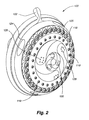
- FIGS. 1-6 show the concentric dual turbine showerhead 100 .
- the larger outer turbine 102 is positioned in an outer annular channel 104 into which water flows. The incoming water impacts the turbine, causing it to spin. Part of the turbine blades are blocked off, and part are not blocked off, causing a pulsating effect in the resulting spray as the turbine spins.
- the smaller turbine 106 is positioned inside of and concentric to the larger turbine 102 , and operates the same way. It is positioned in a smaller circular channel 108 positioned within the outer annular channel 104 . Both turbines spin generally around the same axis, which in this embodiment is may be positioned so that they spin around different axes, with one turbine still inside the other turbine.
- An orifice cup 110 is positioned over the top of the two turbine channels 104 , 108 and attached to the showerhead 100 .
- the orifice cup has orifices 112 , or nozzles, formed therein for emitting the pulsating spray.
- the orifice cup 110 has an outer circular channel 114 to match the outer annular channel 104 , and has an inner circular channel 116 to match the smaller circular channel 108 .
- the other spray modes are sent through apertures 118 , 119 formed outside of and around the concentric turbine section. These other spray modes may emanate in combination with, or separately from, the aforementioned pulsating spray mode.
- the showerhead is generally made of a series of plates having channels and holes formed therein to direct the water to the nozzles 118 , 119 corresponding to the selected spray mode(s), as determined by a position of a mode selector 122 .
- a mist control diverts water flow from whatever spray mode is set to various mist apertures 119 , and back, as desired. In some embodiments, the mist control can be set so that both the current spray mode and the mist mode are actuated at the same time.
- FIG. 2 shows a front perspective view of the showerhead 100 of FIG. 1 , with the mode control ring 124 on the perimeter of the showerhead.
- the regular spray mode orifices 118 are positioned around the perimeter of the front face 126 , with the mist spray mode orifices 119 forming a circle inside the regular spray mode orifices 118 .
- the outer pulsating mode orifices 128 are typically positioned in groups inside the mist spray mode orifices 119 , and communicate with the channel 104 in which the larger turbine 102 is positioned.
- the inner pulsating mode orifices 130 are generally positioned in groups inside the outer pulsating mode orifices 128 , and communicate with the channel 108 in which the smaller turbine 106 is positioned.
- FIG. 3 depicts another embodiment 132 of the present invention, and also shows the channel 108 for the smaller turbine 106 offset forwardly from the channel 104 for the larger turbine 102 , which conforms with the rounded face 126 of the showerhead 132 .
- FIG. 4 shows the concentric turbine design in a showerhead 132 that incorporates only one other spray mode—namely, from orifices 118 positioned around the perimeter of the front face of the showerhead.
- the plate style of the internal structure associated with this type of showerhead 100 is shown in FIG. 5 , where there are two modes separate from the turbine pulse spray modes.
- the mode ring 124 fits around the perimeter of the front engine plate 134 , and engages and acts to rotate a plate (not shown) positioned behind the front engine plate to divert water to the selected modes.
- the outer spray ring and nozzle plate 136 fits on the front of the front engine plate 134 and has an outer channel 138 that mates up with the outer channel 140 on the front engine plate 134 to form a water cavity to supply water to the outer ring orifices 118 when that mode is selected.
- the mist mode spray ring and nozzle plate 142 fits on the front of the front engine plate 134 , inside the outer spray ring and nozzle plate 136 .
- the mist mode spray ring and nozzle plate 142 defines at least one channel 144 that matches with the corresponding channel 146 formed in the front of the front engine plate 134 . It forms a water cavity to supply water to the mist mode orifices 119 when that mode is selected.
- the dual orifice cup 110 fits on the front of the front engine plate 134 to form the annular channels 104 , 108 for holding the turbines 102 , 106 .
- the orifice cup 110 has an outer channel 114 to mate with an outer turbine channel 148 on the front engine plate 134 .
- the turbine 102 uses the inner circumferential wall 150 of that channel as a race about which to spin.
- the orifice cup 110 forms an inner channel 116 to mate with the front engine plate 134 to form the cavity in which the smaller turbine 106 spins.
- the smaller turbine spins around the central boss 152 used to form the aperture 154 for receiving the fastener used to hold the orifice cup 110 to the showerhead 100 .
- FIG. 6 shows the plate structure for use with the showerhead 132 having only one spray mode separate from the two turbine pulse spray modes.
- the structure is substantially similar to that shown in FIG. 5 .
- the embodiment shown in FIG. 6 includes a front engine plate 156 , an outer spray nozzle assembly 158 , an outer spray ring 160 , and a mode ring 162 .
- the dual orifice cup 110 houses the two turbines 102 , 106 .
- FIGS. 7-12 show two embodiments of a side-by-side dual pulsating showerhead.
- FIGS. 7 and 8 show a showerhead 166 having two spray modes separate from the turbine pulsation modes
- FIGS. 9 and 10 show a showerhead 168 having only one mode separate from the turbine pulsation modes.
- FIG. 7 is a section through both side-by-side turbines 170 , their respective chambers 172 , and the showerhead 166 .
- Each side-by-side turbine 170 resides in its own circular channel 172 formed by the mating of the orifice cup 174 and the front engine plate 176 .
- the routing of the water through this showerhead depends on the mode selector.
- the mode selector can be set to spin either turbine independently, or together at the same time. And depending on the direction of the incoming jets in the turbine cavity 172 , the turbines 170 can be caused to rotate the same direction or opposite directions from one another.
- Each of the side-by-side turbines 170 spin around a central hub 178 formed by the channel cavity 172 in which each turbine is placed.
- the turbines 170 are positioned along a centerline of the showerhead. It is contemplated that the turbines can be asymmetrically positioned on the showerhead if desired.
- one other mode is sprayed through orifices 180 formed on the perimeter of the front face 126 of the showerhead 166 .
- Another mode is sprayed through a pair of laterally-spaced, somewhat triangular orifice groupings 182 formed on either side of the side-by-side turbine locations.
- FIGS. 9 and 10 show similar structure for a showerhead 168 that has only one mode different than the pulsating mode.
- the structure and placement of the side-by-side turbines 170 is substantially similar to that described above.
- each turbine 170 has a series of radially extending blades 186 attached at their inner ends 188 to an inner hub 190 .
- a baseplate 192 (shown by dashed lines) is formed under approximately half of the circle formed by the radiating blades 186 .
- the plate is attached to the hub 190 and the fins 194 (also shown by dashed lines). This plate is positioned against the orifices in the orifice cup 174 to block the water flow therethrough.
- the plate 192 is what causes the pulsation in the flow, as the turbine 170 rotates in the cavity 172 and alternately blocks/allows the water to pass through the orifices.
- the plate can extend more or less than halfway around the circle.
- the fins 194 shown in dashed lines are located on top of the plate.
- the fins 194 in whole-line do not have a plate under them.
- the plate has at least one hole 196 in it to keep the incoming water pressure from trapping the turbine 170 against the side of the cavity 172 having the orifices and keeping the turbine from spinning at all.
- the hole lets water through the plate and releases the pressure sufficiently to allow the turbine to spin.
- FIG. 12 shows an exploded view of the plate structure for the side-by-side dual turbine pulsating flow showerhead 166 , as well as a front view thereof.
- the structure is similar to that described above, and there is an orifice cup 174 for each of the two turbines 170 .
- Each orifice cup 174 is held in place by a fastener 184 positioned through the hub in the orifice plate and fastened to the front engine plate 198 .
- FIGS. 13-16 show the plate structure for the concentric dual turbine pulsating showerhead 100 .
- FIG. 13 is the front side 200 of the front engine plate 134 .
- FIG. 14 is the rear side 202 of the front engine plate 134 , which mates with the front side 204 of a rear engine plate 135 (shown generally in FIG. 15 ).
- FIG. 16 depicts the rear side 206 of the rear engine plate 135 .
- the water flows through one of the three main holes 208 , 210 , 212 , from the rear to the front of the rear engine plate 135 (the small hole is the pause hole to allow some water through and not cause a dead-head in the water flow).
- the water flows through the hole selected by the mode selector (not shown), which is known in the art, and is a plate, controlled by an outside control ring, that has a sealed aperture which fits over any one of the three apertures in plate two in order to direct the water flow into the selected mode.
- the water flows through the hole 208 the water flows to the outer turbine 102 to create the pulsating flow through the outer pulsating flow apertures (see above).
- the water flows through the hole 210 the water flows to the outer most channel 104 and through the apertures 128 formed around the perimeter of the showerhead.
- the water flows through the hole 212 the water flows to the channel 108 directing the flow to the inner turbine 106 .
- the inner and outer turbines cannot be activated at the same time. However, by rearranging the channels and holes accordingly on the plates, the two turbines can be made to operate at the same time, or the turbines and at least one non-pulsating mode may be selected.
- FIGS. 13 and 14 show three inlet jets 214 for the outer turbine channels that are all directed the same way to impinge on the flat, straight turbine blades 186 and drive the turbine 102 around the central hub 178 (as described above). Alternate embodiments may use more or fewer inlet jets. This creates a high-speed pulsating spray.
- FIG. 13 there is a fourth inlet 218 facing against the other three 216 .
- FIGS. 17 and 18 show the showerhead 100 with the faceplate removed to display the relative positioning of the turbines on the front of the front engine plate 134 .
- FIG. 17 depicts the front engine plate in isometric view
- FIG. 18 depicts a wire-frame view of the front engine plate.
- the larger turbine 102 is mounted concentrically around the smaller turbine 106 .
- Each of the turbines is constructed similarly, as described above.
- the turbine has a section that has an inner collar 178 with the turbine blades 186 extending radially outwardly therefrom.
- the collar is the same height as the blades.
- the other section of the turbine has a base plate 192 from which the blades extend upwardly, still oriented radially from the center of the circle formed by the turbine, but with no inner collar.
- the base plate has at least one aperture 196 in it to allow water to pass through and keep the turbine from being trapped in one position and not turn.
- FIGS. 19-23 show the plate structure for the side-by-side dual turbine pulsating showerhead 166 .
- FIG. 19 is the front side 222 of the front engine plate 199 .
- FIG. 20 is the rear side 224 of the front engine plate 199 , which mates with the front side 226 of the rear engine plate 198 (shown in FIG. 21 ).
- FIG. 22 is the rear side 228 of the rear engine plate 198 .
- the water flows through one of the three main holes 230 , 232 , 234 , from the rear to the front of the rear engine plate 198 (note that the small hole is the pause hole 240 , shown on FIG. 22 , to allow some water through and not cause a dead-head in the water flow).
- the water flows through the hole selected by the mode selector (not shown), which is known in the art, and is a plate, controlled by an outside control ring, that has a sealed mode selector outlet aperture which fits over any one of the three apertures in plate two in order to direct the water flow into the selected mode.
- the mode selector rotates relative to the rear engine plate to orient the mode selector outlet hole (in the mode selector plate) over the desired mode selector inlet hole (in the rear engine plate). If the water flows through the hole 230 in the rear engine plate ( FIG. 21 ), the water flows to the orifices 236 around the outer perimeter of the showerhead in the prescribed channel 238 shown in FIG. 20 . If the water flows through the hole 232 in the rear engine plate (see FIG.
- the water flows to the channel 240 marked in FIG. 20 and to the apertures 242 formed laterally of the dual pulse apertures in the showerhead. If the water flows through the hole 234 in the rear engine plate (see FIG. 21 ), the water flows to the channel 244 directing the flow to the two side-by-side turbines 170 (not shown in FIG. 20 ). In this embodiment, the two side-by-side turbines are activated at the same time. However, by rearranging the channels and holes accordingly on the plates, the two turbines can be made to operate separately.
- FIG. 19 depicts three inlet jets 246 for both turbines, all of which are directed the same way to impinge on the flat, straight turbine blades and drive the turbine around the central hub (as described above). Alternate embodiments may use more or fewer inlet jets. This creates a high-speed pulsating spray. In this high-speed pulsating mode, water is supplied to the turbine via the three forward-facing inlet jets 246 .
- FIG. 19 there is a fourth inlet 248 in each of the two turbine cavities 172 , the fourth inlet jet 248 facing against the other three 246 .
- water is supplied to the turbine via two forward-facing inlet jets 246 , and also by a fourth, opposite facing inlet jet 248 .
- the turbines may be slowed by reducing water flow through the turbine channel, rather than providing backflow through an opposite-facing inlet jet 248 .
- Such a solution would reduce overall water output.
- FIG. 23 shows the showerhead 166 with the front plate removed to display the relative positioning of the turbines 170 on the front of the outer spray ring 199 .
- the turbines 170 are mounted side by side along a centerline of the head.
- Each of the turbines is constructed similarly, as described above. These two turbines can be driven by the inlet jets to turn the same way, or the opposite way, of one another.
- the holes formed on the bottom plate of the turbine can be positioned so as to not affect the blocking effect that it has and thus lessen the pulsating qualities.
- the showerhead has a mist control feature to convert from the existing non-mist mode to mist mode and back to the same non-mist mode.
- the mist mode changer is controlled by a lever 247 extending from the showerhead 166 , as shown in FIG. 24 .
- the lever controls a rotating face valve 250 which diverts water flow to either the main mode controller or the mist apertures.
- the mode controller is used to divert water between the various modes other than the mist mode, as is known.
- the other modes are not operable. That is, the mode selector can be rotated, but because no water is flowing to the mode selector, the water stays diverted to the mist mode until the mist mode is turned off.
- the lever 247 is attached to a rack 252 , which in turn is connected to a pinion gear 254 formed on the outer circumference of the face valve.
- the water flows into the head from the shower pipe and into the main inlet aperture 255 in the back of the showerhead.
- the water flows up a channel 256 to the face valve and face valve cavity.
- the face valve rotates between the inlet to the mode selector 258 and the inlet to the mist mode 260 .
- Each of these inlets 228 , 260 has a brace 259 formed across the inlet so that the seal around the outlet aperture of the face valve (O-ring or the like, not shown) does not get caught in the relatively large inlet apertures and wear out quickly.
- the braces keep the seal from deflecting too far into the aperture, and thus keep the seal from being pinched or abraded.
- FIGS. 25 , 26 , and 27 show the pathways 261 from the inlets, terminating in outlet apertures 263 .
- Another embodiment of the present invention may also employ multiple turbines to create multiple massage modes.
- two turbines are employed to create a dual massage mode.
- Alternate embodiments may employ three or more turbines, and may create three or more massage modes.
- the dual turbines may be positioned side-by-side or concentrically. The turbines may spin in the same direction or opposite directions. The turbines may be actuated in separate modes, together in the same mode, or both.
- the present embodiment generally provides a variety of shower spray modes. These spray modes are achieved by channeling water from an inlet orifice affixed to a shower pipe, through one or more flow channels defined in a valve body, through a flow outlet and into a flow passage, through one or more inlet nozzles or apertures, into a backplate channel, optionally across one or more turbines, and out at least one nozzle formed in a faceplate. Turbines are only located in certain, specific backplate channels. The water flow through backplate channels associated with a turbine causes the turbine to rotate, which intermittently interrupts water flow to the nozzles associated with the specific backplate channel. This water flow interruption results in a pulsating spray. Routing of water flow is discussed in more detail below.
- FIG. 28 depicts the faceplate 270 of a showerhead 272 corresponding to the present embodiment.
- the faceplate includes a plurality of nozzles arranged into a variety of groups or forms. Each group of nozzles may be affected by a turbine to create a unique spray mode. Further, two or more groups of nozzles may be simultaneously active, thus combining spray modes. Activation of one or more groups of nozzles is generally achieved by turning the mode ring.
- each group of nozzles is generally mirrored about a horizontal or vertical axis by a corresponding group of nozzles.
- eight center spray nozzles 276 are generally arranged inside an inner triangular face 278 on the right-hand side of the faceplate 270 .
- Eight corresponding center spray nozzles 276 are arranged in a mirror fashion in a second inner triangular face 280 on the left-hand side of the showerhead faceplate, as also shown in FIG. 28 .
- three inner pause nozzles 282 are arranged in a triangular pattern at the center of an inner circular plate 284 generally located in the top portion of the faceplate.
- a mirrored grouping of inner pause nozzles 282 is located in a second inner circular plate 286 generally positioned on the back of the faceplate, also shown in FIG. 28 .
- the various groups of nozzles may produce a variety of shower sprays. These shower sprays may, for example, create a circular spray pattern of different diameters for each nozzle group.
- the group of first body spray nozzles 288 positioned in the two outer triangular faces 290 , 292 and extending outside the outer periphery of the first and second inner circular plates 294 , 296 , forms a circular spray pattern of approximately 6 inches in diameter when measured 18 inches outward from the faceplate.
- the group of first body spray nozzles 288 is typically angled such that individual drops or streams of water making up the first 6 inch diameter shower spray are evenly spaced along the circumference of the spray.
- the diameter of the shower spray generally increases with distance from the faceplate. Accordingly, the 6 inch diameter measurement of the first shower spray pattern applies only at the 18 inch distance from the faceplate previously mentioned. Alternate embodiments may increase or decrease the diameter of any of the spray patterns mentioned herein at any distance from the showerhead faceplate.
- the group of first body spray nozzles 288 includes only every other nozzle along the circumference of the faceplate.
- a group of second body spray nozzles 298 Alternating with the group of first body spray nozzles 288 is a group of second body spray nozzles 298 .
- These second body spray nozzles 298 are generally angled to create a shower spray having a 5 inch diameter when measured 18 inches from the faceplate.
- the spray patterns are varied by changing the angulation of the nozzle groups.
- the group of second body spray nozzles is angled closer towards the center of the faceplate, thus creating a shower spray pattern having a smaller diameter.
- a third group of body spray nozzles 300 is also located on the shower faceplate 270 .
- This third group of spray nozzles generally sits inwardly (towards the center of the faceplate) from the first 288 and second 298 groups of nozzles, and is entirely contained within the two outer triangular faces 290 , 292 .
- the third group of body spray nozzles creates a shower spray pattern of approximately 4 inches in diameter at a distance of 18 inches from the faceplate.
- the third group of body spray nozzles creates a generally circular spray pattern, with each nozzle contributing a jet, stream, or drop of water spaced approximately equidistantly along the circumference of the spray pattern from adjacent jets, drops, or streams of water.
- a fourth group of body spray nozzles 302 is also contained within the two outer triangular faces 290 , 292 .
- the nozzles in this fourth group are spaced inwardly (towards the center of the faceplate) from the third group of body spray nozzles.
- This fourth group of nozzles creates a spray pattern approximately 3 inches in diameter, when measured 18 inches outwardly from the faceplate.
- the faceplate In addition to the inner circular plates 294 , 296 and outer triangular faces 290 , 292 , the faceplate also includes two inner triangular faces 278 , 280 . Each inner triangular face is generally located within an outer triangular face. Located inside each inner triangular face is a group of center spray nozzles 276 . In the present embodiment, each inner triangular face includes 8 center spray nozzles.
- the two groups of center spray nozzles 276 do not cooperate to form a single shower spray pattern. Rather, each group of center spray nozzles creates a separate circular shower spray pattern.
- each group of center spray nozzles creates a separate circular shower spray pattern.
- two substantially identical spray patterns are formed substantially adjacent one another. These center spray patterns are approximately 1 inch in diameter each when measured 18 inches outward from the faceplate, and may overlap either at the 18 inch measuring point, prior to this point, or after this point. Further, the center sprays are generally orthogonal from the pulsing sprays emitted from the groups of massage nozzles.
- the groups of massage nozzles 303 may each emit a pulsating spray.
- the pulsation speed of such sprays may vary, and may be selected by turning the mode ring.
- the pulsating spray (and pulsation speed) is controlled by the rotation of one or more turbines 304 .
- the turbines include a series of vanes 306 upon which water flow impacts, imparting rotational energy to the turbines.
- a shield 308 extends across a portion of the turbines. The shield momentarily blocks one or more of the massage nozzles; as the turbine rotates, the massage nozzles blocked by the shield vary. The blocking of nozzles momentarily interrupts water flow through these nozzles, creating the aforementioned pulsating spray.
- each group of nozzles has been described as creating a separate spray pattern
- the present embodiment may activate multiple groups of nozzles simultaneously.
- multiple nozzle groups discussed above may be simultaneously activated, resulting in a combination spray mode.
- multiple spray patterns are formed (i.e., two or more separate spray patterns are simultaneously active).
- the water pressure of the water flow through the embodiment is sufficient to maintain at least two spray patterns simultaneously; in some embodiments three or more spray patterns may be simultaneously active.
- Various embodiments may permit the activation of any combination of the aforementioned spray patterns.
- each spray pattern has been given at a distance of 18 inches from the faceplate, it should be noted that the spray patterns may maintain their form at any distance up to approximately 24 inches or more from the showerhead. In the present embodiment, the optimum range for the formation of spray pattern is generally from 12 to 24 inches. After a distance of 24 inches from the faceplate, the spray pattern tends to dissipate. Alternate embodiments may vary this optimum range.
- FIG. 29 shows a perspective view of the present embodiment of a dual massage showerhead 310 .
- the mode ring 312 , base cone 314 , and a portion of the connection structure 316 may be seen.
- FIG. 30 is a cross-section view of the present embodiment, taken along line A-A of FIG. 29 .
- FIG. 30 shows the relationship between and positioning of various elements of the present embodiment.
- the faceplate 270 is located at one end of the embodiment, generally opposite a shower pipe connector 318 .
- a mode ring 312 Located partially beneath and adjacent to the faceplate is a mode ring 312 .
- the mode ring freely rotates about the stationary faceplate.
- the back side of the faceplate 270 is connected to the front side of a backplate 320 .
- Backplate channels 372 are defined by sidewalls 324 , 326 extending from the back side of the faceplate 270 and front side of the backplate 320 , generally abutting one another.
- a turbine 304 may be positioned in any of the backplate channels 322 .
- the sidewalls 324 , 326 extending from the back side of the faceplate 270 and the front side of the backplate 320 may be sonically welded, heat welded, or chemically bonded to one another (or otherwise affixed to one another) to affix the faceplate to the backplate.
- the back side of the backplate is connected to the front side of a valve body 328 .
- Sidewalls 330 extend from the back side of the backplate 320 and abut matching sidewalls 332 extending from the front side of the valve body 328 , to define one or more flow passages 334 .
- the sidewalls extending from the back side of the backplate and front side of the valve body may be sonically welded, or otherwise affixed to, one another to affix the backplate to the valve body.
- a connector structure 316 extends rearwardly from the valve body and engages a similar, mating structure formed on a base cone 314 .
- the connector structure and base cone are threadedly attached to one another, although in alternate embodiments they may be affixed through sonic welding, heat welding, or an adhesive.
- the mode ring 312 may be freely turned to vary the shower spray patterns when the embodiment is active.
- the mode ring engages an actuator ring 336 , which lies at least partially within the mode ring 312 and beneath the faceplate 270 .
- the actuator ring generally controls the opening and closing of one or more flow channels 334 within a valve body located directly adjacent to the actuator ring. More specifically, one or more plungers 338 may move radially inwardly towards the longitudinal axis (or center) of the present embodiment or radially outwardly away from the longitudinal axis (or center) of the present embodiment as the actuator ring turns.
- a flow channel 334 is closed when the associated plunger 338 is seated in a radially inward position, i.e., is moved towards the center of the embodiment.
- the inward radial movement of a plunger is controlled by one or more actuator ramps, described in more detail below with reference to FIGS. 34-36 .
- a corresponding flow channel 334 is opened through the valve. This permits water to flow through the valve, along the opened channel, and through at least one passage defined by one side of the valve body 328 and the backside of the adjacent backplate 320 .
- the outward motion of a plunger is caused by water pressure exerting force on the portion of the plunger closest to the center of the valve, as described in more detail below. Presuming the plunger is properly aligned with an appropriate actuation point defined on the actuator ring, the water pressure forces the plunger along the flow channel until a flow outlet is exposed.
- the actuation points, flow channels, and flow outlets are described in more detail below.
- Each flow channel 334 permits water to be fed to one or more groups of nozzles. Accordingly, as the mode 312 and actuator 336 ring turns, different plungers 338 move outwardly and inwardly, thus opening or closing different flow channels. In turn, the flow channels permit water to flow to different groups of nozzles. In this manner, a operator may select which groups of nozzles are active at any given moment by turning the mode ring.
- the operation of the actuator ring, backplate, valve body, and plungers is described in more detail below.
- a connector structure 316 typically affixes the valve body 328 to the shower plate connector.
- the connector structure 316 generally is only in direct contact with the valve body 328 , a portion of the shower pipe connector, and possibly a base cone or other covering. As shown in FIG. 30 , interlocking teeth, grooves, or flanges may secure the connector structure to a base cone 314 .
- the base cone in turn, generally covers the various internal components mentioned herein and provides an aesthetic finish.
- the connector body 316 may be formed unitarily with (and thus as an extension of) the valve body 328 , as shown in more detail in FIG. 31 .
- FIG. 31 shows a cross-section of the present embodiment, taken along line B-B of FIG. 29 .
- FIG. 31 depicts the same internal elements as shown in FIG. 30 , albeit in a cross-section perpendicular to that shown in FIG. 30 .
- FIG. 31 depicts the connection structure 316 extending downwardly from the valve body 328 . Additionally, FIG. 31 depicts an anti-rotation 340 structure extending downwardly from the valve body. This anti-rotation structure generally prevents the valve from turning as the mode ring 312 and actuator ring 336 rotate.
- the anti-rotation structure 340 may, for example, be received in a corresponding cavity formed on the base cone 314 . Alternately, and as shown in FIG. 31 , the anti-rotation structure may be seated between multiple prongs 342 extending from the base cone 314 . These prongs generally abut the side of the anti-rotation structure and resist rotational movement.
- the anti-rotation structure of the valve abuts a prong which forces the valve to remain stationary.
- the actuator ring 336 slides across the top and side of the valve body 328 without rotating the valve body itself.
- FIG. 32 depicts a lateral cross-section of the present embodiment, taken along line C-C of FIG. 29 .
- the actuator ring 336 , valve 328 , and plungers 344 , 346 , 348 , 350 , 352 , 354 are shown.
- the actuator ring 336 is affixed to the mode ring 312 by one or more pins 356 . These pins fit in recesses along the exterior of the actuator ring 336 .
- the pins 356 are sonically welded, heat welded, or chemically bonded (for example, by an adhesive) to both the mode ring and actuator ring. Alternate embodiments may directly connect the mode and actuator rings, for example by means of sonic or heat welding.
- Various elements may be sonically welded to one another, such as the backplate and faceplate, both discussed below.
- Yet another alternate embodiment may form the actuator ring 336 and mode ring 312 as a unitary element.
- FIG. 34 depicts the front of the actuator ring.
- FIG. 35 is an isometric view of the actuator ring.
- FIG. 36 is a rear view of the actuator ring.
- the sidewalls 358 of the actuator ring define an interior circular shape having one or more ramps 360 extending therefrom. These ramps terminate in an actuation point 362 .
- FIG. 34 depicts two upper ramps leading to an upper actuation point.
- the inner, generally circular surface 364 of the actuator ring is formed from a series of flat, planar segments 360 .
- the upper ramp and upper actuation points are also formed from such planar segments.
- the inner circle, ramps, and actuation points of the actuation ring may not be formed from planar segments. For example, smooth curves could define any or all of these.
- the upper ramps 360 extend generally outwardly from the center of the actuator ring and define a depression or cavity of a greater radius than the interior circular ring 364 of the actuator 336 .
- the upper ramps 360 terminate at the aforementioned upper actuation point 362 .
- the distance between the upper actuation point and the center of the actuator ring is generally greater than the distance between the center of the actuator ring and the sidewalls of the inner ring or the upper ramps.
- a collar 368 extends downwardly from the main body 370 of the actuator ring 336 .
- this collar generally follows the contour of the previously mentioned inner ring with one exception.
- the collar extends to form a pair of lower ramps 372 terminating in a lower actuation point 374 .
- the distance from the center of the actuator ring 336 to the lower actuation point 374 is generally equal to the distance from the actuator ring center to the upper actuation point.
- the height of the lower actuation point is bounded by a ledge 376 .
- the ledge extends from the inner sidewall of the collar 368 toward the center of the actuator ring 336 .
- An inner actuator wall 378 extends generally upwardly from the innermost portion of the ledge.
- FIG. 31 depicts the collar 368 , ledge 376 , and inner actuator wall 378 of the actuator ring 336 in cross-section.
- the height of the lower actuation point 374 is approximately half the height of the collar.
- the height of the upper actuation point 362 is typically equal to the collar height. In other words, while the ledge limits the height of the lower actuation point, it does not impact the height of the upper actuation point.
- FIG. 32 depicts a lateral cross-section through the actuator ring and valve body, it may be seen that a first plunger 344 is recessed from the center 380 of the valve. The outer end of the first plunger rests against the upper actuation point 362 . Similarly, a second plunger 346 is also recessed from the center of the valve. Although not visible in FIG. 32 , the outer end of the second plunger rests against the lower actuation point (also not shown). By contrast, the third 348 , fourth 350 , fifth 352 and sixth 354 plungers are seated with the inner ends of the plungers flush against the hexagonally-shaped valve center 380 .
- plungers When the plungers are positioned radially outwardly from the valve center (as is the case with the first and second plungers), water may flow through a corresponding hole in the valve center (hole not shown) and through the flow channel opened by the recessed plunger.
- plungers extend radially outwardly when aligned with an appropriate actuation point.
- the alignment of plunger and appropriate actuation point permits water pressure (generated by water flow through the shower connector and into the valve center) to depress the plunger. Effectively, the water pressure acts to force a plunger radially outwardly against an actuation point, thus opening the flow channel for the water's continued flow.
- the valve body 328 defines one or more flow channels 382 , extending radially from a central water port. Each flow channel leads to a flow outlet 384 (shown to best effect in FIG. 44 ). As also shown in FIG. 33 , a plunger 338 is located inside each flow channel 382 . The plunger may move radially along the flow channel, alternating between an inner, closed and sealed position and an outer, open and unsealed position.
- water may flow from the central water inlet, along the flow channel, and to the flow outlet to which the flow channel leads.
- water flowing through a flow outlet exits the present embodiment through one or more corresponding nozzles.
- the plunger 338 moves radially outwardly from its inner, sealed position under the force of water pressure. This motion, however, may only be accomplished when the outer end of the plunger aligns with an actuator ramp 360 , 372 or actuation point 362 , 374 defined on the actuator ring 336 .
- the actuator ring fits around the outer ends of the flow channels 382 to typically limit the outward radial motion of the plungers, and to force each plunger inwardly as the actuator ring turns.
- the actuation points however, have a greater radius (measured from the center of the actuator ring and/or valve body) than does the rest of the actuator ring. See, for example, FIG. 34 . Thus, the actuation point permits outward motion of a plunger.
- an actuation point 375 is aligned with a plunger 338 by rotation of the mode ring 312 , and corresponding rotation of the actuator ring 336 .
- the outer end of the plunger engages the actuator ramp 373 , which gradually forces the plunger radially inward, returning the plunger to a seated position. This cuts off water flow through the flow channel, out through the flow outlet, and through the corresponding nozzle(s).
- the actuator ring 336 may have one or more actuator ramps 373 leading to an actuation point.
- the front and rear edges of the actuator ring define the position of each plunger in the flow channel. Each edge defines a profile, which either permits the plunger to move to a radially outwardly extending (unsealed) position or pushes the plunger inwardly to an inner, sealed position.
- the actuator ring “clicks” or times the position of the plungers to allow or control the water flow to the various nozzles being actuated by the actuator ring.
- each plunger 338 generally includes a curved lower surface 383 and an extended upper surface 384 .
- the extended upper surface generally projects farther than the curved lower surface from the base 386 of the plunger.
- the rear wall 388 of the extended upper surface is substantially flat.
- the front wall 390 of the curved lower surface is arcuate.
- the combination of front 390 and rear walls 388 creates a “D” shape in lateral cross-section.
- This D-shape mates with the D-shaped flow channels, as described in more detail below with respect to FIG. 41 .
- the plunger 338 may include a first 392 and second 394 O-ring seat point. Each seat point may accept an O-ring 396 (shown in FIG. 32 ). When seated, the outer surface of each O-ring 396 , 397 generally extends slightly outwardly past the sidewall 398 of the lower portion of the plunger.
- the O-rings are typically made of neoprene rubber or a similar water-tight sealing material.
- the inner O-ring 396 i.e., the O-ring in the second O-ring seat point, shown in FIG. 40 . Accordingly, water may flow past the front of the plunger and at least partially down the flow channel.
- the outer O-ring 397 i.e., the O-ring seated in the first O-ring seat point 392 , shown in FIG. 40 ) maintains its contact with the sidewall 400 of the flow channel 382 .
- the diameter of the inner O-ring seat point 392 is larger than the diameter than the outer O-ring seat point 394 .
- the relative diameters of the O-ring seat points are shown to best effect in FIG. 39 , while contact (or lack thereof) between the O-rings and the flow channel sidewalls is shown to best effect in FIG. 32 .
- the first plunger 344 in FIG. 32 is in an actuated (radially outwardly extended) position. Accordingly, water may flow past the inner O-ring 396 of the first plunger 344 , but not past the outer O-ring 397 of the first plunger.
- the third plunger 348 is in a seated (radially inward) position.
- both the inner 396 and outer 397 O-rings of the third plunger contact the scalloped walls 402 of the flow channel 382 .
- the inner O-ring 396 may contact the flow channel sidewall 400 while in a seated position and not contact the flow channel sidewalls in an actuated position.
- the outer O-ring 397 maintains contact with the flow channel sidewalls regardless of whether the plunger is in an actuated position or not.
- the second 346 , third 348 , and sixth 354 plungers are oriented with the curved lower surface 383 above the extended upper surface 384 .
- the back wall 388 of these plungers sits further into the valve and farther away from the faceplate 270 than the front wall 390 .
- the first 344 , fourth 350 , and fifth 352 plungers are oriented in exactly the opposite manner. That is, the extended upper surface 384 overlies the curved lower surface 383 in these plungers. This orients the back wall 388 closer to the faceplate 270 than the front wall (i.e., closer to the front of the embodiment). Effectively, the first 344 , fourth 350 , and fifth 352 plungers are oriented 180 degrees from the second 346 , third 348 , and sixth 354 plungers.
- the orientation of the plungers 344 , 346 , 348 , 350 , 352 , 354 directly affects which actuation points on the actuation ring 336 will permit water pressure to force the plungers radially outwardly.
- the first 344 , fourth 350 , and fifth 352 plungers may only be forced radially outwardly when aligned with the upper actuation point 362 .
- the inner actuator wall 378 (see FIG. 31 ) abuts the top of the extended upper surface 384 , keeping the plungers in a radially inward, closed position.
- the second 346 , third 348 , and sixth 354 plungers may be forced radially outwardly to an open position by water pressure when aligned with either the upper 362 or lower actuation points 374 .
- the second, third, and sixth plungers behave in the same manner as the first, fourth, and fifth plungers.
- the extended upper surface sits beneath the ledge and inner actuator wall. This permits water pressure to force these plungers radially outwardly until the curved lower surface of the plunger contacts the inner actuator wall; the extended upper surface slides beneath the ledge and into the lower actuation point.
- the second plunger 346 in FIG. 32 for example, is in such a position.
- the actuation ring 336 is designed in such a manner that the upper actuation point 362 permits movement of any plunger with which it is aligned, while the lower actuation point 374 permits movement only of properly oriented plungers.
- planar segments 366 making up the inner ring 378 of the actuator 336 generally prevent movement of any adjacent plungers.
- the length of each planar segment is approximately equal to the width of the extended upper surface of the plunger 384 (see, for example, FIG. 33 ). This facilitates a firm connection between the planar segments 366 of the inner ring 378 and the extended upper surface 384 of the plungers.
- the upper 360 and lower ramps 372 permit plungers to gradually slide radially outwardly until the flow channel 382 is fully opened with the plungers seated against the appropriate actuation point, instead of abruptly transitioning a plunger from a closed (inner) to an open (outer) position.
- plungers would abruptly unseat and reseat within the valve, thus causing water flow through the flow channels to vary from non-existent to full flow. Further, moving the plunger inwardly would require excessive force in the absence of the ramps. By permitting such gradual changes in flow, water transition between groups of nozzles is gradual. This, in turn, permits the operator time to acclimate from one spray pattern to the next as the mode ring is turned. It should be noted the mode ring and actuator ring may be turned in either a clockwise or counter-clockwise direction.
- each plunger actuates a different one of the spray modes described with respect to FIG. 28 . That is, when a given plunger extends radially outwardly and opens a corresponding flow channel, a specific spray mode is activated. For example, when the first plunger 344 shown on FIG. 32 is radially outwardly extended and the corresponding flow channel 382 is open, any of the first, second, third, and fourth body spray patterns mentioned with respect to FIG. 28 may be active. This is also true when the second plunger 346 shown on FIG. 32 is radially outwardly extended.
- valve 328 defines six flow channels and includes six plungers seated therein, alternate embodiments may employ more or fewer flow channels and plungers.
- the actuator ring 336 discussed herein may have more or fewer upper actuation or lower actuation points without the departing from the spirit or scope of the invention.
- some embodiments may employ an actuator ring wherein the orientation of the ledge and inner actuator wall are reversed. That is, the inner actuator wall may extend towards the back of the embodiment (i.e., towards the shower pipe conductor structure) instead of towards the front of the embodiment, thus defining a “partial upper-actuation point.”
- the orientation and position of the plungers may be varied in alternate embodiments.
- the present invention contemplates and embraces any combination of upper and/or lower actuation points spaced along the actuator ring, flow channels, and/or plungers.
- FIG. 33 is a perspective view of the present embodiment with the base cone 314 removed. This figure depicts the lower actuation point 374 of the actuator ring 336 with an exemplary plunger 338 in the open or flow position. This view also generally depicts the valve body 328 and anti-rotation mechanism 340 , as well as the mating between actuator ring 378 and valve 328 . In the present embodiment, one or more prongs abut the top or sides of the valve, while the collar 368 of the actuator ring 336 sits beneath the valve body 328 . The actuator ring is typically not bonded to the valve, but instead may freely rotate about the valve while the prongs maintain the connection there between.
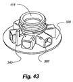
- FIGS. 41 through 44 depict various views of the valve body 328 .
- FIG. 41 is a side view of the valve, showing the connector structure 316 extending from the valve body 328 .
- the anti-rotation device 340 may also be seen.
- three flow channels 404 , 406 , 408 are visible.
- one plunger is at least partially seated within each flow channel 404 , 406 , 408 .
- the wall of each flow channel is generally “D” shaped to match the cross-section of a plunger, and to ensure proper plunger orientation during assembly of the embodiment.
- some flow channels have a “D” shaped cross-section rotated 180 degrees from other flow channels.
- the first flow channel 404 i.e., the rightmost flow channel in FIG. 41
- a second flow channel 406 i.e., the leftmost flow channel in FIG. 41
- Plungers may simply be rotated 180 degrees as necessary to fit within either type of flow channel without requiring structural modifications.
- plungers 338 seated within a flow channel having a “back side flat” configuration may be actuated by the either the upper 362 or lower actuation 374 points of the actuator ring 336 .
- the extended upper surface 384 of the plunger may extend beneath the inner wall 378 of the actuator ring, thus permitting the plunger to move radially outwardly within the flow channel.
- plungers 338 seated in a “front side flat” flow channel may only actuate when aligned with the upper actuation point 362 of the actuator ring 336 .
- the inner wall 378 of the actuator ring engages the extended upper surface 384 of the plunger, thus preventing radial outward motion in response to water pressure.
- the sidewalls 400 of the flow channel 404 , 406 , 408 are not uniform in cross-sectional shape.
- the outer ends 410 of the flow channel sidewalls assume the aforementioned “D” shaped cross-section, while the inner ends of the flow channel sidewalls 366 are generally circular in cross-section.
- the inner end of the flow channel is shaped with scalloped or stair-step profile sidewalls, transitioning from a larger diameter circular cross-section (nearer the outer end of the flow channel) to a smaller diameter circular cross-section (nearer the inner end of the flow channel).
- each plunger 338 engages the sidewalls of the flow channel, with the inner O-ring 396 contacting the sidewall of the flow channel having a smaller circumference and the outer O-ring 397 contacting the sidewall of the flow channel having a larger circumference, while the plunger is in an inner, or sealed, position.
- the inner O-ring extends outwardly past the innermost scalloped section of the flow channel, and disengages from the flow channel sidewall.
- the outer O-ring 397 maintains contact with the sidewall even while the plunger is in a radially-outwardly extended position.
- FIG. 42 depicts a rear view of the valve 328 .
- the outer housing 412 of each flow channel, the connection structure 316 , and the anti-rotation structure 340 may be seen. Also visible is the central water port, and the top of a hexagonal seating point 341 .
- the hexagonal seating point accepts the inner end of the plungers 338 when the plungers occupy an inner, sealed position.
- FIG. 43 depicts an isometric view of the valve 328 .
- the transition between the “D” shaped and generally circular cross-sections of a flow channel 382 may partially be seen.
- the central water port 414 which channels water from the shower pipe to the center of the valve and through any open flow channels, may also be seen.
- the anti-rotation structure 340 of the valve is also visible.
- plungers 338 and flow channels 382 have been generally described as “D”-shaped in cross section, alternate embodiments may employ plungers and flow channels having different cross-sectional configurations.
- some embodiments may employ plungers 338 and flow channels 382 having a “double D” or hourglass configuration, while others may use different spline-type shapes.
- the plungers and flow channels may have triangular, rectangular, rhomboidal, and yet other geometric shapes in cross-section, as well as asymmetric shapes.
- FIG. 44 depicts the front surface 416 of the valve 328 .
- the front surface of the valve generally defines a number of passages 334 .
- Each passage is bounded by sidewalls 332 extending outwardly form the valve front.
- six flow passages are defined in the front of the valve. Alternate embodiments may define more or fewer flow passages.
- Each flow passage is associated with a flow channel via a flow outlet, Further, and as discussed in more detail below, each flow passage leads to an inlet nozzle or aperture, to a backplate channel, and ultimately to one or more nozzles or apertures formed on the faceplate.
- At least one flow outlet 384 is present within each of the flow passages 334 .
- Each flow outlet extends through the valve 328 front and into a discrete flow passage.
- water may flow through the valve 328 , into the flow passage 334 , and outwardly through the flow outlet 384 .
- Some passages may contain multiple flow outlets.
- flow passage “B” contains two flow outlets, while flow passage “A” contains a single flow outlet.
- flow outlet refers to the aperture in the valve top permitting water flow from the flow channel to the valve top surface.
- FIG. 45 depicts the rear of the backplate 320 .
- Sidewalls 330 extend outwardly from the backplate rear.
- the backplate sidewalls 330 typically abut (and are sonically welded to) the valve front sidewalls 332 .
- the pattern of sidewalls on the rear of the backplate is a mirror image of the sidewall pattern on the valve front.
- both the valve front sidewalls and the backplate rear sidewalls contribute to define the flow passages 334 , as do the front of the valve and the rear of the backplate themselves.
- the backplate 330 rear contains no flow outlets. Instead, the flow channels defined on the rear of the backplate include at least one inlet nozzle 418 or backplate aperture 421 . Accordingly, in the present embodiment water flows into the valve center 380 from a shower pipe, along a flow channel and at least partially past a radially outwardly extended plunger, through a flow outlet, into a flow passage, along the flow passage, and out either an inlet nozzle or an aperture. Water may then flow through a backplate channel, potentially across a turbine, and out an aperture or nozzle formed on the faceplate.
- the backplate flow channels are generally formed on the front of the backplate as shown in FIG. 46 .
- the backplate channels are defined by one or more front backplate sidewalls 326 .
- the front backplate sidewalls 326 shown to better effect in the isometric view of FIG. 47 .
- the various backplate channels 422 , 424 , 426 , 428 correlate with different nozzle groups located on the faceplate front and discussed with respect to FIG. 28 .
- the first backplate channel 422 corresponds to the outer massage nozzles 303 of the first (upper) inner circular plate
- the second backplate 424 channel corresponds to the outer massage nozzles 303 of the second (lower) inner circular plate.
- the inner backplate channel 426 corresponds to the center spray nozzles 276 defined in the inner triangular faces 278 , 280 .
- the outer backplate channel 428 corresponds to the first 288 , second 298 , third 300 , and fourth 302 groups of body spray nozzles.
- water is simultaneously supplied to the first through fourth groups of body spray nozzles, and accordingly all the corresponding body spray patterns are simultaneously active.
- the first through fourth body spray patterns may be active singly or in other combinations.
- FIG. 48 depicts a side view of the backplate, also showing a front and backplate sidewall.
- the front backplate sidewalls 326 define first 422 and second 424 circular backplate channels.
- Each of the first and second circular backplate channels is fed by multiple inlet nozzles 408 .
- four inlet nozzles feed each circular backplate channel.
- more or fewer inlet nozzles may be employed per circular backplate channel. It may also be seen that one of the four inlet nozzles is oriented in an opposite direction with respect to the other three inlet nozzles in each backplate channel.
- inlet nozzles A, G, and H are oriented such that water flowing out of these nozzles enters the circular backplate channel flowing at a generally clockwise direction, looking at the front of the backplate.
- This clockwise water flow impacts one or more vanes of a turbine (shown in FIG. 50 ), thus imparting rotational motion to the turbine.
- the rotational motion results in the pulsating spray through the massage nozzles, as discussed in more detail below.
- nozzle C emits water into the circular backplate channel 422 flowing in a generally counter-clockwise position.
- inlet nozzle C may emit water into the first circular backplate channel simultaneously with one or more of nozzles A, G, and H.
- this reverse flow through inlet nozzle C acts to counter at least a portion of the water pressure resulting from flow through one or more inlet nozzles A, G, and H, by impacting the turbine vanes and imparting rotational energy in a direction opposite that imparted by flow through nozzles A, G, and H.
- inlet nozzle C emits water simultaneously with one of inlet nozzles A, G, or H
- the water pressure in the first circular backplate is decreased, the turbine spins more slowly, and the pulsation of spray through the outer massage nozzles is slowed.
- all inlet nozzles 408 may all be oriented to emit water in the same direction, resulting in additive flow through multiple nozzles and thus increased water pressure.
- a high pressure/turbine rotation mode i.e., a high pulsating mode
- a low pressure/turbine rotation mode is achieved when a single nozzle permits flow into the circular backplate channel.
- the positioning of the first 422 and second 424 circular backplate channel generally corresponds to the positioning of the two inner circular plates 294 , 296 on the faceplate of the present embodiment. (These inner circular plates were discussed with reference to FIG. 28 , and are shown in more detail on FIG. 51 .) Still with reference to FIG. 46 , a turbine generally sits within the first circular backplate channel 422 .
- One example of a turbine 304 is shown in FIG. 49 .
- the hollow inner portion 430 of the turbine shown in FIG. 49 fits around the inner sidewall 432 of the first circular backplate channel 422 .
- a similar turbine assembly is mounted within the second circular backplate channel 424 .
- the vaned extensions 424 of the turbine generally face the front of the showerhead, towards the front of the backplate.
- the flow impacts the vanes of the turbine, imparting clockwise rotational energy to the turbine.
- back flow or reverse flow
- this back flow imparts rotational energy in a direction opposite to that imparted by the flow emitted from inlet nozzles A, G, or H. Accordingly, the rotation of the turbine is slowed.
- the turbine 304 may operate at two different speeds.
- the turbine may operate in a first, high-speed mode when flow into the first circular backplate channel 422 occurs only through inlet nozzles A, G, and H.
- the turbine 304 may operate in a second, low-speed mode when flow into the first circular backplate channel 422 occurs through inlet nozzles A, G, and H, and simultaneously in an opposite direction through inlet nozzle C. This same operation is true with respect to the turbine located in the second circular backplate 424 channel.
- the rotational speed of the turbine 304 dictates the pulsation speed of water jets emerging from any of the outer massage nozzles 303 . Slower rotational speeds yield slower water jet pulsation, while higher rotational speeds yield faster water jet pulsation.
- the shield 308 extending along a portion of the turbine circumference momentarily blocks one or more outer massage nozzles. When these nozzles are blocked, water flow from the circular backplate channel, through the turbine vanes 434 , and out through the outer massage nozzles 303 is interfered with. Thus, the water flow out of the faceplate is momentarily interrupted. As the turbine revolves, the shield moves to block different sets of outer massage nozzles. This intermittent blocking of outer massage nozzles produces the aforementioned pulsating effect.
- the present embodiment employs two circular backplate channels and two turbines
- alternate embodiments may employ more or fewer backplate channels and turbines.
- multiple turbines may be arranged concentrically instead of in a side-by-side manner.
- FIG. 50 depicts the backside of the faceplate 270 .
- Faceplate sidewalls 324 extend outwardly from the back of the faceplate. These faceplate sidewalls 324 generally abut the front sidewalls 326 of the backplate 320 to form the various backplate channels, in much the same manner as flow channels are defined by the combination of the front valve sidewalls and rear backplate sidewalls.
- the sidewalls 324 of the faceplate 270 may also be sonically welded to the front backplate sidewalls 326 , or otherwise affixed thereto in any manner known to those skilled in the art (for example, by an adhesive heat bonding, etc.)
- the defined backplate channels selectively guide water to certain groups of nozzles. As can be seen in FIG.
- the inner pause and outer massage nozzles 282 , 303 generally penetrate the faceplate and terminate in the first 422 and second circular 424 backplate channels.
- the first through fourth sets of body spray nozzles 288 , 298 , 300 , 302 penetrate the faceplate and enter an outer backplate channel 428 .
- the water when water travels through the backplate via aperture I- 1 , the water enters and fills the outer backplate channel, and is emitted through one or more of the first through fourth groups of body spray nozzles.
- one or more of the first, second, third, and fourth groups of the body spray nozzles may be selectively blocked to permit greater control over the shower spray pattern.
- the rear of the faceplate 270 and the front of the backplate 320 also combine to define an inner backplate channel.
- the inner backplate channel 426 directs water to center spray nozzles 276 located in the inner triangular faces 278 , 280 (see, for example, FIG. 28 ). It should be noted the inner backplate channel directs water across the length of the backplate and faceplate, in a direction generally transverse to other flow channels or backplate channels. The inner backplate channel directs water flow between the two circular backplate channels.
- FIG. 51 depicts the front of the faceplate 270 .
- the close-up view shown in FIG. 51 clearly depicts the first 288 , second 298 , third 300 , and fourth 302 groups of body spray nozzles, the center spray nozzles 276 , the outer massage nozzles 303 , the inner pause nozzles 282 , the outer triangular faces 290 , the inner triangular faces 280 , and the inner circular plates 284 .
- FIG. 52 depicts a side view of the front plate 270 used in the present embodiment
- FIG. 53 depicts the same faceplate in an isometric view.
- alternate embodiments may employ faceplates having different nozzle groups, inner or outer triangular faces, inner circular plates, and so forth. Generally speaking any nozzle pattern or nozzle grouping desired may be implemented in a faceplate of an alternate embodiment.
- the present embodiment contemplates switching of a mode ring by unscrewing or otherwise removing the mode ring.
- the mode ring 312 is depicted in FIG. 54 .
- Another embodiment of the present invention may vary certain internal elements, such as the holes in the valve body leading to the flow channels and plungers, to achieve a variety of shower effects. For example, the pause mode may be so enhanced.
- small holes in the backplate 370 (shown within the inner sidewalls 432 in FIG. 46 , and also depicted in FIG. 45 ) restrict the flow of water in the flow channel 334 associated with the fourth plunger 350 .
- This restriction results in a trickle emanating from the inner pause nozzles 282 (shown in FIG. 50 ), which are the only outlets for that particular flow channel 334 .
- a hole 538 of limited cross-sectional area in a valve center 580 of a valve body 528 may be employed within the path from the valve center 580 to a flow channel 582 associated with a fourth plunger 550 , as depicted in the cross-sectional view of a showerhead 510 in FIG. 55 .
- the narrow hole 538 in fluid communication with the valve center 580 and the flow channel 582 thereby restricts the flow of water into the flow channel 582 , thus maintaining the majority of the back pressure resulting from the limited water flow in the valve center 582 , thereby reducing the pressure on the fourth plunger 550 while in pause mode due to the limited cross-sectional area against which fluid flow may exert pressure.
- the torque required to rotate the actuator ring (not shown in FIG. 55 ) out of pause mode is reduced accordingly.
- the narrower hole 538 is not employed in flow channels associated with other showerhead modes, unless a lower level of water flow is desired.
- the reduced width of the narrow hole 538 provides less water flow (and thus less external water pressure) than a nominal hole 540 , such as associated with a first plunger 544 .
- varying widths of holes in the valve body, or the flow channels themselves may be used in conjunction with differing levels of water flow to substantially equalize the torque required to switch out of each available mode provided by the showerhead 510 , or adjust the water pressure of various spray patterns. For example, larger or smaller diameter spray patterns may be provided with differing pressure levels to enhance massage.
- a variety of faceplates and/or base cones may be chosen prior to sonic welding of components to provide a number of different aesthetic appearances. This may change the appearance of the embodiment by substituting colored or decorative faceplates, base cones having different shapes or colors, and so forth.
Landscapes
- Nozzles (AREA)
- Bathtubs, Showers, And Their Attachments (AREA)
- Massaging Devices (AREA)
Abstract
Description
Claims (14)
Priority Applications (3)
| Application Number | Priority Date | Filing Date | Title |
|---|---|---|---|
| US12/426,786 US8020788B2 (en) | 2002-12-10 | 2009-04-20 | Showerhead with enhanced pause mode |
| US13/020,783 US8905332B2 (en) | 2002-12-10 | 2011-02-03 | Dual turbine showerhead |
| US14/563,674 US9795975B2 (en) | 2002-12-10 | 2014-12-08 | Dual turbine showerhead |
Applications Claiming Priority (4)
| Application Number | Priority Date | Filing Date | Title |
|---|---|---|---|
| US43246302P | 2002-12-10 | 2002-12-10 | |
| US10/732,385 US7114666B2 (en) | 2002-12-10 | 2003-12-09 | Dual massage shower head |
| US10/931,505 US7520448B2 (en) | 2002-12-10 | 2004-08-31 | Shower head with enhanced pause mode |
| US12/426,786 US8020788B2 (en) | 2002-12-10 | 2009-04-20 | Showerhead with enhanced pause mode |
Related Parent Applications (1)
| Application Number | Title | Priority Date | Filing Date |
|---|---|---|---|
| US10/931,505 Continuation US7520448B2 (en) | 2002-12-10 | 2004-08-31 | Shower head with enhanced pause mode |
Related Child Applications (1)
| Application Number | Title | Priority Date | Filing Date |
|---|---|---|---|
| US13/020,783 Continuation US8905332B2 (en) | 2002-12-10 | 2011-02-03 | Dual turbine showerhead |
Publications (2)
| Publication Number | Publication Date |
|---|---|
| US20090314858A1 US20090314858A1 (en) | 2009-12-24 |
| US8020788B2 true US8020788B2 (en) | 2011-09-20 |
Family
ID=32717729
Family Applications (5)
| Application Number | Title | Priority Date | Filing Date |
|---|---|---|---|
| US10/732,385 Expired - Lifetime US7114666B2 (en) | 2002-12-10 | 2003-12-09 | Dual massage shower head |
| US10/931,505 Expired - Fee Related US7520448B2 (en) | 2002-12-10 | 2004-08-31 | Shower head with enhanced pause mode |
| US12/426,786 Expired - Fee Related US8020788B2 (en) | 2002-12-10 | 2009-04-20 | Showerhead with enhanced pause mode |
| US13/020,783 Active 2024-10-21 US8905332B2 (en) | 2002-12-10 | 2011-02-03 | Dual turbine showerhead |
| US14/563,674 Expired - Lifetime US9795975B2 (en) | 2002-12-10 | 2014-12-08 | Dual turbine showerhead |
Family Applications Before (2)
| Application Number | Title | Priority Date | Filing Date |
|---|---|---|---|
| US10/732,385 Expired - Lifetime US7114666B2 (en) | 2002-12-10 | 2003-12-09 | Dual massage shower head |
| US10/931,505 Expired - Fee Related US7520448B2 (en) | 2002-12-10 | 2004-08-31 | Shower head with enhanced pause mode |
Family Applications After (2)
| Application Number | Title | Priority Date | Filing Date |
|---|---|---|---|
| US13/020,783 Active 2024-10-21 US8905332B2 (en) | 2002-12-10 | 2011-02-03 | Dual turbine showerhead |
| US14/563,674 Expired - Lifetime US9795975B2 (en) | 2002-12-10 | 2014-12-08 | Dual turbine showerhead |
Country Status (5)
| Country | Link |
|---|---|
| US (5) | US7114666B2 (en) |
| AU (1) | AU2003296462A1 (en) |
| DE (1) | DE10393869T5 (en) |
| TW (1) | TW200424016A (en) |
| WO (1) | WO2004061243A2 (en) |
Cited By (29)
| Publication number | Priority date | Publication date | Assignee | Title |
|---|---|---|---|---|
| US20110017842A1 (en) * | 2009-07-01 | 2011-01-27 | Derek Michael Nations | Rotary Irrigation Sprinkler With A Turret Mounted Drive System |
| US20110114754A1 (en) * | 2009-11-18 | 2011-05-19 | Huasong ZHOU | Hydropower rotating overhead shower |
| US20110121098A1 (en) * | 2002-12-10 | 2011-05-26 | Water Pik, Inc. | Dual turbine showerhead |
| USD673649S1 (en) | 2012-01-27 | 2013-01-01 | Water Pik, Inc. | Ring-shaped wall mount showerhead |
| USD674050S1 (en) | 2012-01-27 | 2013-01-08 | Water Pik, Inc. | Ring-shaped handheld showerhead |
| US20130248621A1 (en) * | 2012-03-21 | 2013-09-26 | So Mei Huang | Multi-stage showerhead for preventing mixed-flow and back-pressure |
| US8584972B2 (en) | 2006-12-29 | 2013-11-19 | Water Pik, Inc. | Handheld showerhead with fluid passageways |
| US8757517B2 (en) | 2008-09-15 | 2014-06-24 | Water Pik, Inc. | Showerhead with flow directing plates and radial mode changer |
| US9120111B2 (en) | 2012-02-24 | 2015-09-01 | Rain Bird Corporation | Arc adjustable rotary sprinkler having full-circle operation and automatic matched precipitation |
| US9127794B2 (en) | 2007-05-04 | 2015-09-08 | Water Pik, Inc. | Pivot attachment for showerheads |
| US9156043B2 (en) | 2012-07-13 | 2015-10-13 | Rain Bird Corporation | Arc adjustable rotary sprinkler with automatic matched precipitation |
| USD744066S1 (en) | 2014-06-13 | 2015-11-24 | Water Pik, Inc. | Wall mount showerhead |
| USD744064S1 (en) | 2014-06-13 | 2015-11-24 | Water Pik, Inc. | Handheld showerhead |
| USD744065S1 (en) | 2014-06-13 | 2015-11-24 | Water Pik, Inc. | Handheld showerhead |
| USD744612S1 (en) | 2014-06-13 | 2015-12-01 | Water Pik, Inc. | Handheld showerhead |
| USD744614S1 (en) | 2014-06-13 | 2015-12-01 | Water Pik, Inc. | Wall mount showerhead |
| USD744611S1 (en) | 2014-06-13 | 2015-12-01 | Water Pik, Inc. | Handheld showerhead |
| USD745111S1 (en) | 2014-06-13 | 2015-12-08 | Water Pik, Inc. | Wall mount showerhead |
| US9295997B2 (en) | 2013-05-10 | 2016-03-29 | Speakman Company | Showerhead having structural features that produce a vibrant spray pattern |
| US9404243B2 (en) | 2013-06-13 | 2016-08-02 | Water Pik, Inc. | Showerhead with turbine driven shutter |
| USD803981S1 (en) | 2016-02-01 | 2017-11-28 | Water Pik, Inc. | Handheld spray nozzle |
| US9925545B2 (en) | 2014-08-28 | 2018-03-27 | Nebia Inc. | Immersive showerhead |
| US10226777B2 (en) | 2012-06-22 | 2019-03-12 | Water Pik, Inc. | Showerhead bracket |
| USD843549S1 (en) | 2017-07-19 | 2019-03-19 | Water Pik, Inc. | Handheld spray nozzle |
| US10265710B2 (en) | 2016-04-15 | 2019-04-23 | Water Pik, Inc. | Showerhead with dual oscillating massage |
| US10441960B2 (en) | 2016-09-08 | 2019-10-15 | Water Pik, Inc. | Pause assembly for showerheads |
| US10449558B2 (en) | 2016-02-01 | 2019-10-22 | Water Pik, Inc. | Handheld pet spray wand |
| USD872227S1 (en) | 2018-04-20 | 2020-01-07 | Water Pik, Inc. | Handheld spray device |
| USD970684S1 (en) | 2016-04-15 | 2022-11-22 | Water Pik, Inc. | Showerhead |
Families Citing this family (55)
| Publication number | Priority date | Publication date | Assignee | Title |
|---|---|---|---|---|
| US7740186B2 (en) | 2004-09-01 | 2010-06-22 | Water Pik, Inc. | Drenching shower head |
| US20060196971A1 (en) * | 2005-03-01 | 2006-09-07 | Lau Ping W | Shower head |
| EP1712290A1 (en) * | 2005-04-13 | 2006-10-18 | I.M.P.A. F.LLI Togno S.r.l. | Shower spray system with double function modes |
| US7818828B2 (en) * | 2005-09-13 | 2010-10-26 | Hua-Song Zhou | Multi-functional shower head |
| US7100845B1 (en) * | 2005-10-24 | 2006-09-05 | Elvis Hsieh | Switch-equipped sprinkler |
| US7854401B2 (en) * | 2005-12-14 | 2010-12-21 | Moen Incorporated | Faucet wand |
| WO2007124455A2 (en) | 2006-04-20 | 2007-11-01 | Water Pik, Inc. | Converging spray showerhead |
| US7694897B2 (en) * | 2006-04-20 | 2010-04-13 | Moen Incorporated | Integrated multi-function showerhead |
| US20080083844A1 (en) * | 2006-10-09 | 2008-04-10 | Water Pik, Inc. | Showerhead attachment assembly |
| US8020787B2 (en) | 2006-11-29 | 2011-09-20 | Water Pik, Inc. | Showerhead system |
| US8366024B2 (en) | 2006-12-28 | 2013-02-05 | Water Pik, Inc. | Low speed pulsating showerhead |
| US7770822B2 (en) | 2006-12-28 | 2010-08-10 | Water Pik, Inc. | Hand shower with an extendable handle |
| US8794543B2 (en) | 2006-12-28 | 2014-08-05 | Water Pik, Inc. | Low-speed pulsating showerhead |
| US7374112B1 (en) | 2007-04-19 | 2008-05-20 | Moen Incorporated | Interleaved multi-function showerhead |
| US7670305B2 (en) * | 2007-11-13 | 2010-03-02 | Sam Zhadanov | Device for showering and turbo-rotative water treatment |
| US8104697B2 (en) * | 2008-03-19 | 2012-01-31 | Petrovic John E | Fluid spray control device |
| DE102008015967A1 (en) | 2008-03-20 | 2009-09-24 | Hansgrohe Ag | shower head |
| DE102008015968A1 (en) | 2008-03-20 | 2009-09-24 | Hansgrohe Ag | shower head |
| USD624156S1 (en) | 2008-04-30 | 2010-09-21 | Water Pik, Inc. | Pivot ball attachment |
| US7918408B2 (en) * | 2008-08-14 | 2011-04-05 | Globe Union Industrial Corp. | Hand-held showerhead structure |
| USD616061S1 (en) | 2008-09-29 | 2010-05-18 | Water Pik, Inc. | Showerhead assembly |
| USD625776S1 (en) | 2009-10-05 | 2010-10-19 | Water Pik, Inc. | Showerhead |
| US8276834B2 (en) * | 2009-10-12 | 2012-10-02 | Globe Union Industrial Corp. | Multi-function shower head |
| US8297534B2 (en) * | 2009-11-18 | 2012-10-30 | Xiamen Solex High-Tech Industries Co., Ltd. | Shower with rotatable top and bottom rotating covers |
| US20130032647A1 (en) * | 2009-11-25 | 2013-02-07 | Xiamen Solex High-Tech Industries Co., Ltd. | Outlet unit with socket |
| US20110139905A1 (en) * | 2009-12-14 | 2011-06-16 | Huasong ZHOU | Rotary switched shower and its method of switching |
| US8915455B2 (en) * | 2009-12-25 | 2014-12-23 | Xiamen Solex High-Tech Industries Co., Ltd. | Massage shower that can achieve the dynamic switch of the water flow |
| WO2011110081A1 (en) * | 2010-03-09 | 2011-09-15 | 厦门松霖科技有限公司 | Mechanism for switching discharge by plugging in or unplugging |
| CN102258421B (en) * | 2010-05-25 | 2015-11-25 | 皇家飞利浦电子股份有限公司 | For transmitting the equipment of mist to face |
| US8616470B2 (en) | 2010-08-25 | 2013-12-31 | Water Pik, Inc. | Mode control valve in showerhead connector |
| US20120074178A1 (en) * | 2010-09-24 | 2012-03-29 | Jun Zhang | Dispensing device with multiple openings for bottle |
| US20120074179A1 (en) * | 2010-09-27 | 2012-03-29 | Allen & Thomas Cosmetic Accessories Co., Ltd. | Bottle with Multiple Openings |
| WO2012041356A1 (en) * | 2010-10-01 | 2012-04-05 | Grohe Ag | Spray head |
| CN102580869B (en) * | 2011-01-05 | 2013-12-25 | 厦门松霖科技有限公司 | Sprinkler |
| US8632023B2 (en) * | 2011-06-07 | 2014-01-21 | Masco Corporation Of Indiana | Push button mechanism for showerhead control |
| US8567700B2 (en) | 2011-06-29 | 2013-10-29 | Christopher Miedzius | Showerhead with 360 degree rotational spray control |
| US10464079B2 (en) * | 2011-11-28 | 2019-11-05 | Xiamen Solex High-Tech Industries Co., Ltd. | Concealed top cover-type shower head |
| CN102527529B (en) * | 2011-12-20 | 2013-12-25 | 厦门松霖科技有限公司 | Sprinkler with function of alternately spraying water |
| US8985483B2 (en) | 2012-01-24 | 2015-03-24 | John E. Petrovic | Adjustable trajectory spray nozzles |
| CA2906221C (en) * | 2013-03-15 | 2021-10-19 | As Ip Holdco, Llc | Multifunction faucet spray head |
| US9216424B2 (en) * | 2013-06-11 | 2015-12-22 | Am Conservation Group, Inc. | System and method of selective fluid pattern distribution |
| DE102014200741A1 (en) * | 2014-01-16 | 2015-07-16 | Hansgrohe Se | Shower with multi-channel jet outlet units |
| WO2017027720A1 (en) * | 2015-08-11 | 2017-02-16 | Dlhbowles, Inc. | Fluidic faucet spray face and spray generation method |
| CN205056287U (en) * | 2015-09-26 | 2016-03-02 | 厦门建霖工业有限公司 | Rotatory splash of face lid spills |
| GB2548339A (en) * | 2016-03-09 | 2017-09-20 | Kohler Mira Ltd | Spray head |
| CN108499759B (en) * | 2017-02-24 | 2024-01-09 | 厦门松霖科技股份有限公司 | Water outlet device capable of switching different water outlet patterns at same water outlet hole |
| US10603681B2 (en) * | 2017-03-06 | 2020-03-31 | Engineered Spray Components LLC | Stacked pre-orifices for sprayer nozzles |
| CN107260527A (en) * | 2017-07-25 | 2017-10-20 | 梁景青 | A kind of cold and hot mixed type humidification facial vaporizer |
| US10232391B2 (en) * | 2017-07-27 | 2019-03-19 | Deborah Timmerman | Dispensing attachment for a shower head |
| CN112292212B (en) * | 2018-06-29 | 2022-11-15 | 洁碧有限公司 | Pause assembly for showerhead |
| CN209317943U (en) * | 2018-09-03 | 2019-08-30 | 厦门英仕卫浴有限公司 | A kind of energy-efficient pulsating water discharging device |
| SG11202103233TA (en) * | 2018-10-02 | 2021-04-29 | Gjosa Sa | Atomiser and showerhead |
| GB2578593B (en) * | 2018-10-31 | 2020-11-25 | Kohler Mira Ltd | Spray head |
| US10946395B2 (en) * | 2019-02-06 | 2021-03-16 | Kevin J. Medeiros | Shower head |
| US20230089835A1 (en) * | 2021-09-20 | 2023-03-23 | Water Pik, Inc. | Showerhead with massage engine |
Citations (876)
| Publication number | Priority date | Publication date | Assignee | Title |
|---|---|---|---|---|
| US203094A (en) | 1878-04-30 | Improvement in armor for flexible tubing | ||
| US204333A (en) | 1878-05-28 | Improvement in sprinklers | ||
| US309349A (en) | 1884-12-16 | Eobeet haet | ||
| US428023A (en) | 1890-05-13 | Casing for flexible shafts | ||
| US432712A (en) | 1890-07-22 | George taylor | ||
| US445250A (en) | 1886-02-24 | 1891-01-27 | Flexible piping for pneumatic brakes | |
| US453109A (en) | 1891-05-26 | Duplex eccentric-valve for heaters | ||
| US486986A (en) | 1892-07-27 | 1892-11-29 | Submerged pipe | |
| US566410A (en) | 1892-07-27 | 1896-08-25 | Submerged pipe | |
| US566384A (en) | 1896-08-25 | Sprinkling-can | ||
| US570405A (en) | 1896-04-18 | 1896-10-27 | Flexible pipe-joint | |
| US694888A (en) | 1901-08-21 | 1902-03-04 | Anton John Pfluger | Umbrella-support. |
| US800802A (en) | 1905-06-24 | 1905-10-03 | Gustave Eward Franquist | Shaft-coupling. |
| US832523A (en) | 1904-09-01 | 1906-10-02 | Frank H Kasperson | Flexible tubing. |
| US835678A (en) | 1905-08-28 | 1906-11-13 | Robert L Hammond | Horn-support. |
| US845540A (en) | 1906-02-28 | 1907-02-26 | Robert T Ferguson | Valve. |
| US854094A (en) | 1906-09-22 | 1907-05-21 | Ralph Abraham Schoenberg | Electrical conductor and armor therefor. |
| US926929A (en) | 1908-07-27 | 1909-07-06 | Silas V Dusseau | Combined driving and steering wheel for automobile-axles. |
| US1001842A (en) | 1908-05-02 | 1911-08-29 | Edwin T Greenfield | Hose. |
| US1003037A (en) | 1909-10-13 | 1911-09-12 | Paul L Crowe | Speed-regulator releasing mechanism. |
| US1018143A (en) | 1910-07-01 | 1912-02-20 | Harry Vissering And Company | Sand-pipe for sander devices. |
| US1046573A (en) | 1911-11-13 | 1912-12-10 | Wm F Wolff Company | Electric-light bracket. |
| US1130520A (en) * | 1913-08-20 | 1915-03-02 | Andrew E Kenney | Curtainless shower-bath. |
| US1203466A (en) | 1916-02-29 | 1916-10-31 | Leonard R Benson | Bath-brush. |
| US1217254A (en) | 1913-12-23 | 1917-02-27 | George W Winslow | Deep-sea-salvage-recovering apparatus. |
| US1218895A (en) | 1914-02-10 | 1917-03-13 | Edwin H Porter | Pipe for the conveyance of fluids. |
| US1255577A (en) | 1917-01-31 | 1918-02-05 | Edward Francis Berry | Flexible pipe-coupling or flexible pipe. |
| US1260181A (en) | 1917-06-06 | 1918-03-19 | John Garnero | Self-leveling table. |
| US1276117A (en) | 1917-06-13 | 1918-08-20 | Rogers Motor Lock Company | Flexible armored conduit. |
| US1284099A (en) | 1915-08-12 | 1918-11-05 | Lewis F Harris | Pipe-coupling. |
| GB129812A (en) | 1918-07-19 | 1919-07-21 | W H Dorman And Company Ltd | Improvements in Ball and Socket Joints particularly for Flexible Pipe Lines. |
| US1327428A (en) | 1919-08-16 | 1920-01-06 | George H Gregory | Adjustable shower-spray device |
| DE352813C (en) | 1922-05-04 | Bernhard Eckardt | Connection hose with protective cover for railroad cars | |
| FR538538A (en) | 1921-07-20 | 1922-06-10 | Flexible knuckle enhancements for diver's clothing | |
| US1451800A (en) | 1921-06-09 | 1923-04-17 | Raymond C Agner | Flexible conduit |
| US1459582A (en) | 1921-06-04 | 1923-06-19 | Dubee Adelard Joseph | Brush and mop holder |
| US1469528A (en) | 1921-05-07 | 1923-10-02 | Owens John | Metal hose |
| GB204600A (en) | 1922-12-07 | 1923-10-04 | Gwynnes Engineering Company Lt | Improvements in or connected with pipe-ball-joints |
| US1500921A (en) | 1919-06-21 | 1924-07-08 | Bramson Mogens Louis | Flexible pipe line |
| US1560789A (en) | 1922-03-25 | 1925-11-10 | Sf Bowser & Co Inc | Hose holder |
| US1597477A (en) | 1924-07-21 | 1926-08-24 | Test Tite Company | Shower-bath head |
| US1633531A (en) | 1927-06-21 | Spray disk and method and apparatus for makino the same | ||
| US1692394A (en) | 1925-10-29 | 1928-11-20 | Sundh August | Flash light |
| US1695263A (en) | 1927-06-07 | 1928-12-11 | Adams Ind Inc | Flexible tubular conduit |
| US1724147A (en) | 1929-02-16 | 1929-08-13 | Corey L Russell | Shower fixture |
| US1724161A (en) | 1928-01-31 | 1929-08-13 | Maximillian W Wuesthoff | Shower-bath fixture |
| US1736160A (en) | 1929-01-02 | 1929-11-19 | Automotive Royalties Corp | Lubricating device |
| US1754127A (en) | 1924-10-20 | 1930-04-08 | Firm Of Alex Friedmann | Pipe coupling |
| US1758115A (en) | 1929-01-12 | 1930-05-13 | James W Kelly | Adjustable shower fixture |
| US1778658A (en) | 1925-08-22 | 1930-10-14 | V V Fittings Company | Swivel joint for electrical fittings |
| US1821274A (en) | 1926-07-01 | 1931-09-01 | Pacific Coast Eng Co | Flexible pipe-joint |
| US1849517A (en) | 1930-07-09 | 1932-03-15 | Speakman Co | Shower head |
| US1890156A (en) | 1929-07-24 | 1932-12-06 | Konig Wenzel | Shower rose |
| US1906575A (en) | 1930-11-03 | 1933-05-02 | Oscar C Goeriz | Ball joint for pipe lines |
| US1934553A (en) | 1931-07-23 | 1933-11-07 | Mueller Co | Spray head |
| US1946207A (en) | 1928-09-10 | 1934-02-06 | George W Haire | Plumbing installation |
| US2011446A (en) | 1935-01-14 | 1935-08-13 | Milwaukee Flush Valve Company | Bathtub shower-spout fixture |
| US2024930A (en) | 1935-08-12 | 1935-12-17 | Milwaukee Flush Valve Company | Plumbing fixture |
| US2033467A (en) | 1935-06-07 | 1936-03-10 | Pierce John B Foundation | Air valve-vacuum breaker |
| US2044445A (en) | 1934-11-05 | 1936-06-16 | Price Emil | Shower head |
| US2085854A (en) | 1935-04-18 | 1937-07-06 | Mueller Co | Shower head and method of making the same |
| US2096912A (en) | 1936-05-18 | 1937-10-26 | George J Morris | Shower head |
| US2117152A (en) | 1935-06-26 | 1938-05-10 | Crosti Pietro | Pipe joint |
| US2196783A (en) | 1938-09-12 | 1940-04-09 | Titan Metal Mfg Company | Plumbing fixture |
| US2197667A (en) | 1938-12-14 | 1940-04-16 | Titan Metal Mfg Company | Shower bath fixture |
| US2216149A (en) | 1938-03-08 | 1940-10-01 | Samuel L Weiss | Swiveling bracket |
| US2251192A (en) | 1938-09-08 | 1941-07-29 | Mueller Co | Shower head |
| US2268263A (en) | 1941-05-15 | 1941-12-30 | Dresser Mfg Company | Pipe fitting |
| US2285831A (en) | 1939-05-29 | 1942-06-09 | Kay R Braly | Shower bath spray head |
| FR873808A (en) | 1939-12-11 | 1942-07-21 | Deutsche Schiff & Maschb Ag | Adjustable pressure oil sprayer |
| US2342757A (en) | 1940-04-20 | 1944-02-29 | Leslie W Roser | Nozzle |
| CH234284A (en) | 1943-10-25 | 1944-09-15 | Paul Camzi Jules | Device for using a "portable shower" as a fixed shower. |
| US2402741A (en) | 1944-10-03 | 1946-06-25 | Adolphe O Draviner | Spray head |
| US2467954A (en) | 1946-02-23 | 1949-04-19 | Rodger F Becker | Flashlight |
| GB634483A (en) | 1947-12-05 | 1950-03-22 | Telegraph Constr & Maintenance | Improvements in and relating to submarine cable repeater housings |
| US2546348A (en) | 1947-08-19 | 1951-03-27 | Dresser Ind | Service head fitting |
| US2567642A (en) | 1947-03-11 | 1951-09-11 | Nu Swift Ltd | Nozzle for the discharge of liquids |
| US2581129A (en) | 1947-06-14 | 1952-01-01 | Henry Hyman | Portable electric flashlight with retractable mount for auxiliary lamps |
| DE848627C (en) | 1950-01-19 | 1952-09-04 | Richard Hammerschmidt | Holding device for a hose shower |
| DE854100C (en) | 1943-03-06 | 1952-10-30 | Ludwig Dipl-Ing Dr-Ing Grassl | Flexible bracket |
| US2648762A (en) | 1950-12-16 | 1953-08-11 | Milton S Dunkelberger | Combined housing and flexible flashlight support |
| FR1039750A (en) | 1950-07-15 | 1953-10-09 | Thermostat | |
| US2664271A (en) | 1951-12-06 | 1953-12-29 | Arutunoff Armais | Sealing device for tubular shafting |
| US2671693A (en) | 1952-03-18 | 1954-03-09 | Hyser | Spray nozzle |
| US2676806A (en) | 1948-05-29 | 1954-04-27 | Columbia Broadcasting Syst Inc | Phonograph reproducer arm assembly |
| US2679575A (en) | 1950-07-20 | 1954-05-25 | David D La Vine | Portable reading lamp |
| US2680358A (en) | 1952-05-14 | 1954-06-08 | John A Zublin | Flexible conduit for high-pressure fluid |
| FR1098836A (en) | 1954-03-31 | 1955-08-22 | Semi-flexible tube | |
| US2726120A (en) | 1951-06-15 | 1955-12-06 | Ralph E Bletcher | Shower head |
| US2759765A (en) | 1954-07-19 | 1956-08-21 | Leon P Pawley | Flexible shower head |
| US2776168A (en) | 1954-09-20 | 1957-01-01 | Rufin L Schweda | Extension and telescoping attachment for nozzle of showers |
| US2792847A (en) | 1953-02-09 | 1957-05-21 | Spencer Lloyd | Mixing valves |
| US2873999A (en) | 1956-06-21 | 1959-02-17 | Ernest C Webb | Adjustable support for a shower head |
| US2930505A (en) | 1959-02-10 | 1960-03-29 | Robert J Meyer | Wall insert for setting bathroom fixtures |
| US2931672A (en) | 1956-06-05 | 1960-04-05 | George W Merritt | Flexible duct mounting |
| US2935265A (en) | 1959-01-21 | 1960-05-03 | Herbert M Richter | Jet-aerator spray shower-head |
| US2949242A (en) | 1958-12-02 | 1960-08-16 | Blumberg Benjamin | Shower head |
| US2957587A (en) | 1957-04-15 | 1960-10-25 | Tobin Arthur | Guard and shelf for shower handles |
| US2966311A (en) | 1958-07-24 | 1960-12-27 | Harold G Davis | Adjustable shower attachment |
| US2992437A (en) | 1958-11-28 | 1961-07-18 | Logan Mfg Company | Prefabricated multi-station plumbing fixture |
| US3007648A (en) | 1959-04-20 | 1961-11-07 | Speakman Co | Shower head having a constant volume automatic flow control device therein |
| US3032357A (en) | 1960-05-19 | 1962-05-01 | Sidney J Shames | Flexible shower arm |
| US3034809A (en) | 1960-08-08 | 1962-05-15 | Greenberg Harold Jay | Universal ball and socket joint |
| US3037799A (en) | 1959-09-11 | 1962-06-05 | Rudolph A Mulac | Universal ball and socket joint |
| CA659510A (en) | 1963-03-12 | N. Bard Francis | Ball joint | |
| US3081339A (en) | 1957-06-06 | 1963-03-12 | Polaroid Corp | Derivatives of nitro and amino aralkylene thio-hydroquinone-o, o'-diacetate and preparation thereof |
| US3092333A (en) | 1957-10-16 | 1963-06-04 | Gaiotto Battista | Spray nozzle |
| US3098508A (en) | 1959-05-08 | 1963-07-23 | Gerdes Claus-Holmer | Mixing valve |
| US3103723A (en) | 1960-08-22 | 1963-09-17 | Aero Motive Mfg Company | Inspection device |
| US3104815A (en) | 1963-09-24 | Illuminated sprinkler | ||
| US3104827A (en) | 1963-09-24 | Vandal-proof aerator | ||
| US3111277A (en) | 1961-01-31 | 1963-11-19 | Henry Hyman | Portable electric flashlight |
| US3112073A (en) | 1963-02-01 | 1963-11-26 | Clifford B Larson | Flexible spot rinsing head for shower baths |
| US3143857A (en) | 1960-05-02 | 1964-08-11 | Star Fire Marine Jet Company | Combined forward and reverse steering device for jet propelled aquatic vehicles |
| GB971866A (en) | 1963-08-23 | 1964-10-07 | Henry Hyman | Portable electric flashlight |
| US3196463A (en) | 1962-05-23 | 1965-07-27 | Clayton S Farneth | Ankle joint for artificial limb |
| US3231200A (en) | 1963-08-05 | 1966-01-25 | Sam Heald Co | Shower head and liquid soap dispensing and metering means |
| US3236545A (en) | 1961-07-20 | 1966-02-22 | George L Parkes | Cam bushing for conduits |
| US3239152A (en) | 1964-05-04 | 1966-03-08 | Chicago Specialty Mfg Co | Aerating device |
| US3266059A (en) | 1963-06-19 | 1966-08-16 | North American Aviation Inc | Prestressed flexible joint for mechanical arms and the like |
| US3272437A (en) | 1964-07-27 | 1966-09-13 | Gen Sprinkler Company | Rotary pop-up sprinkler employing a fixed cam |
| US3273359A (en) | 1963-01-11 | 1966-09-20 | Banner Company | Sinker cap mechanism for circular knitting machines |
| US3306634A (en) | 1963-02-07 | 1967-02-28 | Pul Vac Inc | Articulate joint |
| US3323148A (en) | 1964-12-11 | 1967-06-06 | Burnon David | Stretching clamp for upholstery webbing |
| US3329967A (en) | 1965-03-31 | 1967-07-11 | Henry J Martinez | Diving suit |
| US3341132A (en) | 1965-02-18 | 1967-09-12 | American Standard Inc | Spout diverter valve |
| US3342419A (en) | 1965-01-04 | 1967-09-19 | Harry Swartz | Dispensing shower head |
| US3344994A (en) | 1966-04-08 | 1967-10-03 | Crane Co | Shower head having removable spray former to permit cleaning |
| US3363842A (en) | 1965-10-05 | 1968-01-16 | Robert L. Burns | Fire hose nozzle |
| GB1111126A (en) | 1964-05-12 | 1968-04-24 | Crosweller & Co Ltd W | Improvements in, or relating to, spray nozzles |
| US3383051A (en) | 1966-01-10 | 1968-05-14 | Speakman Co | Shower head |
| US3389925A (en) | 1965-08-06 | 1968-06-25 | Ehrenreich & Cie A | Ball joints, especially for steering gears |
| US3393312A (en) | 1966-07-18 | 1968-07-16 | Frank L. Dahl | Adjustable flashlight |
| US3393311A (en) | 1965-09-09 | 1968-07-16 | Frank L. Dahl | Adjustable trouble lamp means |
| US3404410A (en) | 1966-11-30 | 1968-10-08 | Kunio A. Sumida | Shower device |
| US3492029A (en) | 1968-11-18 | 1970-01-27 | Johns Manville | Thermally insulated pipe |
| US3516611A (en) | 1968-06-04 | 1970-06-23 | Spraying Systems Co | Indexable sprayer with plural nozzle orifices |
| US3546961A (en) | 1967-12-22 | 1970-12-15 | Gen Electric | Variable flexibility tether |
| US3550863A (en) | 1968-11-08 | 1970-12-29 | Jane O Mcdermott | Shower apparatus |
| US3552436A (en) | 1967-10-06 | 1971-01-05 | Weldon R Stewart | Valve controlled fluid programmer |
| US3565116A (en) | 1968-09-12 | 1971-02-23 | White Motor Corp | Safety hose and fitting assembly |
| US3566917A (en) | 1968-12-20 | 1971-03-02 | James C White | Fluid manifold |
| US3580513A (en) | 1969-01-31 | 1971-05-25 | American Standard Inc | Shower head |
| US3584822A (en) | 1968-02-26 | 1971-06-15 | John A Oram | Flexible columns |
| US3596835A (en) | 1968-12-26 | 1971-08-03 | Raymond D Smith | Adjustable turret spray nozzle |
| US3612577A (en) | 1968-10-30 | 1971-10-12 | Mirrless Blackstone Ltd | Concentric pipes with drain means |
| US3637143A (en) | 1969-05-28 | 1972-01-25 | Melard Mfg Corp | Handle-controlled spray |
| US3641333A (en) | 1968-12-05 | 1972-02-08 | Everett W Gendron | Illuminated belt |
| US3647144A (en) | 1970-03-31 | 1972-03-07 | American Standard Inc | Swivel spray apparatus |
| US3663044A (en) | 1970-05-04 | 1972-05-16 | Aeroquip Corp | Universal joint |
| US3669470A (en) | 1969-08-12 | 1972-06-13 | Draka Kabel Nv | Connector enclosure |
| US3672648A (en) | 1970-11-27 | 1972-06-27 | Franklin Carr Price | Tuyere assembly |
| US3682392A (en) | 1970-11-25 | 1972-08-08 | Wrightway Mfg Co | Liquid aerating and spraying device |
| US3685745A (en) | 1971-05-19 | 1972-08-22 | Peschcke Andreas P | Adjustable shower apparatus |
| US3711029A (en) | 1971-04-13 | 1973-01-16 | L Bartlett | Spray nozzle |
| US3722798A (en) | 1970-10-29 | 1973-03-27 | Bletcher R | Combined aerator spray assembly |
| US3722799A (en) | 1971-06-16 | 1973-03-27 | Modern Faucet Mfg Co | Adjustable shower head assembly with diverter valve |
| US3731084A (en) | 1972-03-20 | 1973-05-01 | Portable flashlight | |
| US3754779A (en) | 1970-09-04 | 1973-08-28 | J Peress | Flexible joints |
| US3762648A (en) | 1972-06-21 | 1973-10-02 | Teledyne Ind | Spray nozzle |
| US3768735A (en) | 1972-01-07 | 1973-10-30 | I Ward | Combination spray and aerator device |
| US3786995A (en) | 1972-05-03 | 1974-01-22 | Masco Corp | Aerator spray attachment for faucets |
| US3801019A (en) | 1972-06-21 | 1974-04-02 | Teledyne Ind | Spray nozzle |
| US3810580A (en) | 1972-10-30 | 1974-05-14 | Modern Faucet Mfg Co | Adjustable shower head assembly with diverter valve |
| DE2360534A1 (en) | 1972-12-15 | 1974-06-20 | Kamphuis Kunststoffen B V | METHOD OF MANUFACTURING A BALL JOINT FOR A SEWER PIPELINE OR THE SAME, AND MANUFACTURED IN THIS WAY |
| US3826454A (en) | 1972-07-24 | 1974-07-30 | Interbath Inc | Adjustable mounting arrangement for hand-held shower head |
| US3840734A (en) | 1972-10-19 | 1974-10-08 | J Oram | Lighting devices |
| US3845291A (en) | 1974-02-08 | 1974-10-29 | Titan Tool And Die Co Inc | Water powered swimming pool light |
| US3860271A (en) | 1973-08-10 | 1975-01-14 | Fletcher Rodgers | Ball joint pipe coupling |
| US3861719A (en) | 1973-05-09 | 1975-01-21 | James D Hand | Transition pipe fitting |
| US3865310A (en) | 1974-04-12 | 1975-02-11 | Teledyne Ind | Bracket assembly for hand-held showerhead |
| US3869151A (en) | 1974-04-16 | 1975-03-04 | Nasa | Internally supported flexible duct joint |
| US3896845A (en) | 1974-06-13 | 1975-07-29 | Gen Motors Corp | Accumulator charging and relief valve |
| US3902671A (en) | 1973-04-30 | 1975-09-02 | Paul C Symmons | Spray aerator |
| US3910277A (en) | 1973-04-26 | 1975-10-07 | Draegerwerk Ag | Cryoprobe and flexible connector therefor |
| US3929164A (en) | 1971-02-25 | 1975-12-30 | Harold J Richter | Fluid transfer umbilical assembly for use in zero gravity environment |
| US3958756A (en) | 1975-06-23 | 1976-05-25 | Teledyne Water Pik | Spray nozzles |
| US3967783A (en) | 1975-07-14 | 1976-07-06 | Chicago Specialty Manufacturing Company | Shower spray apparatus |
| US3979096A (en) | 1973-11-30 | 1976-09-07 | Interbath, Inc. | Mounting arrangement for hand-held shower head |
| US3997116A (en) | 1975-10-28 | 1976-12-14 | Stanadyne, Inc. | Adjustable shower head |
| US3998390A (en) | 1976-05-04 | 1976-12-21 | Associated Mills, Inc. | Selectable multiple-nozzle showerhead |
| US3999714A (en) | 1975-10-30 | 1976-12-28 | Lang Keith M | Shower head water flow reducing device |
| US4005880A (en) | 1975-07-03 | 1977-02-01 | Dresser Industries, Inc. | Gas service connector for plastic pipe |
| US4006920A (en) | 1975-03-12 | 1977-02-08 | Johns-Manville Corporation | Joint assembly for insulating high temperature fluid carrying conduits |
| US4023782A (en) | 1974-09-06 | 1977-05-17 | S.A. Des Anciens Etablissements Paul Wurth | Tuyere stock and compensator joint therefore |
| US4042984A (en) | 1975-12-31 | 1977-08-23 | American Bath And Shower Corporation | Automatic bathtub water level control system |
| US4045054A (en) | 1972-09-28 | 1977-08-30 | Hydrotech International, Inc. | Apparatus for rigidly interconnecting misaligned pipe ends |
| USD245858S (en) | 1976-11-15 | 1977-09-20 | Associated Mills, Inc. | Handheld showerhead |
| USD245860S (en) | 1976-11-15 | 1977-09-20 | Associated Mills, Inc. | Showerhead |
| US4068801A (en) | 1976-04-19 | 1978-01-17 | Alson's Corporation | Pulsating jet spray head |
| US4081135A (en) | 1976-06-11 | 1978-03-28 | Conair Corporation | Pulsating shower head |
| US4084271A (en) | 1977-01-12 | 1978-04-18 | Ginsberg Irwin L | Steam bath device for shower |
| US4091998A (en) | 1976-11-16 | 1978-05-30 | Associated Mills, Inc. | Retainer clamp |
| USD249356S (en) | 1976-11-01 | 1978-09-12 | Joseph Nagy | Shampoo unit for sink spout or the like |
| US4117979A (en) | 1977-04-15 | 1978-10-03 | Speakman Company | Showerhead |
| US4129257A (en) | 1973-10-23 | 1978-12-12 | Uwe Eggert | Jet mouth piece |
| US4130120A (en) | 1977-04-11 | 1978-12-19 | Kohler Co. | Bathing chamber |
| US4131233A (en) | 1976-08-11 | 1978-12-26 | Shulamith Koenig | Selectively-controlled pulsating water shower head |
| US4133486A (en) | 1977-10-28 | 1979-01-09 | Fanella Michael R | Hair spray assembly |
| US4135549A (en) | 1976-02-18 | 1979-01-23 | Baker Robert W | Swimming pool fluid distribution system |
| USD251045S (en) | 1977-03-09 | 1979-02-13 | Associated Mills, Inc. | Wall mounted bracket for a handheld showerhead |
| US4141502A (en) | 1976-02-18 | 1979-02-27 | Hans Grohe Kg. | Pulsating water jet massage shower head construction |
| US4151955A (en) | 1977-10-25 | 1979-05-01 | Bowles Fluidics Corporation | Oscillating spray device |
| US4151957A (en) | 1977-01-31 | 1979-05-01 | Beatrice Foods Co. | Shower spray apparatus |
| US4162801A (en) | 1977-12-16 | 1979-07-31 | Aeroquip Corporation | Gas line lead-in assembly |
| US4165837A (en) | 1978-03-30 | 1979-08-28 | Associated Mills, Inc. | Power controlling apparatus in a showerhead |
| US4167196A (en) | 1976-12-13 | 1979-09-11 | Acorn Engineering Co. | Vandal-proof plumbing valve access box |
| US4174822A (en) | 1976-09-17 | 1979-11-20 | Nils Larsson | Shower holder |
| US4185781A (en) | 1978-01-16 | 1980-01-29 | Spraying Systems Co. | Quick-disconnect nozzle connection |
| US4190207A (en) | 1978-06-07 | 1980-02-26 | Teledyne Industries, Inc. | Pulsating spray apparatus |
| US4191332A (en) | 1978-01-10 | 1980-03-04 | Langis David J De | Shower head flow control device |
| US4203550A (en) | 1976-12-06 | 1980-05-20 | Hexagear Industries Limited | Shower heads |
| US4209132A (en) | 1977-03-18 | 1980-06-24 | Well Men Industrial Company Limited | Shower spray heads |
| USD255626S (en) | 1977-07-26 | 1980-07-01 | Associated Mills, Inc. | Bracket for hand held showerhead |
| US4219160A (en) | 1978-01-06 | 1980-08-26 | General Electric Company | Fluid spray nozzle having leak resistant sealing means |
| US4221338A (en) | 1979-02-08 | 1980-09-09 | Shames Sidney J | Combination spray and aerator |
| US4243253A (en) | 1979-01-24 | 1981-01-06 | Robertshaw Controls Company | Flexible conduit construction and method of making the same |
| US4244526A (en) | 1978-08-16 | 1981-01-13 | Arth Michael J | Flow controlled shower head |
| US4254914A (en) | 1979-09-14 | 1981-03-10 | Shames Sidney J | Pulsating shower head |
| USD258677S (en) | 1978-11-01 | 1981-03-24 | Arrow Ab | Hand shower |
| US4258414A (en) | 1979-08-01 | 1981-03-24 | Plymouth Products Incorporated | Universal trouble light |
| US4272022A (en) | 1979-10-17 | 1981-06-09 | Zin-Plas Corporation | Showerhead with replaceable housing |
| US4274400A (en) | 1978-12-02 | 1981-06-23 | Baus Heinz Georg | Massage shower having a guide rail |
| US4282612A (en) | 1980-04-28 | 1981-08-11 | King Joseph L | Adjustable shower and massage apparatus |
| USD261300S (en) | 1978-12-15 | 1981-10-13 | Friedrich Grohe Armaturenfabrik Gmbh & Co. | Handshower |
| USD261417S (en) | 1979-03-26 | 1981-10-20 | Friedrich Grohe Armaturenfabrik Gmbh & Co. | Showerhead |
| US4303201A (en) | 1980-01-07 | 1981-12-01 | Teledyne Industries, Inc. | Showering system |
| US4319608A (en) | 1977-05-02 | 1982-03-16 | Raikov Ivan Y | Liquid flow splitter |
| US4330089A (en) | 1979-03-23 | 1982-05-18 | Hans Grohe Gmbh & Co. Kg. | Adjustable massage shower head |
| DE2806093C2 (en) | 1978-02-14 | 1982-05-27 | Hoffmeister-Leuchten GmbH & Co KG, 5880 Lüdenscheid | Connector for busbars |
| USD266212S (en) | 1979-11-15 | 1982-09-21 | Hans Grohe Gmbh & Co. Kg | Wall rail for hand showers |
| US4350298A (en) | 1979-08-16 | 1982-09-21 | Canyon Corporation | Foam dispenser |
| US4353508A (en) | 1980-11-10 | 1982-10-12 | Spraying Systems Company | Nozzle with pre-orifice metering restriction |
| US4358056A (en) | 1979-12-28 | 1982-11-09 | Emmett Laboratories, Inc. | Shower dispenser |
| USD267582S (en) | 1980-10-06 | 1983-01-11 | Teledyne Industries, Inc. | Hand-held showerhead |
| USD268359S (en) | 1980-11-06 | 1983-03-22 | Friedrich Grohe Armaturenfabrik Gmbh & Co. | Shower head |
| USD268442S (en) | 1980-11-13 | 1983-03-29 | Alice Darmon | Lamp |
| USD268611S (en) | 1981-03-16 | 1983-04-12 | Friedrich Grohe Armaturenfabrik Gmbh & Co. | Hand shower |
| GB2068778B (en) | 1980-01-10 | 1983-05-11 | Well Men Ind Co Ltd | Shower spray head |
| US4383554A (en) | 1980-07-31 | 1983-05-17 | Mobil Oil Corporation | Flexible pipe |
| US4396797A (en) | 1980-12-27 | 1983-08-02 | Horiba, Ltd. | Flexible cable |
| US4398669A (en) | 1977-05-09 | 1983-08-16 | Teledyne Industries, Inc. | Fluid-spray discharge apparatus |
| GB2066074B (en) | 1979-12-31 | 1983-12-21 | Sankin Ind Co | Compositions for diagnosis of dental caries activity |
| US4425965A (en) | 1982-06-07 | 1984-01-17 | Otis Engineering Corporation | Safety system for submersible pump |
| US4432392A (en) | 1976-09-29 | 1984-02-21 | Paley Hyman W | Plastic manifold assembly |
| USD274457S (en) | 1981-01-20 | 1984-06-26 | Hans Grohe Gmbh & Co. | Combined side shower heads, hand shower connector and adjustable holder for a hand shower |
| US4461052A (en) | 1982-09-27 | 1984-07-24 | Mostul Thomas A | Scrubbing brush, rinse and sweeping equipment |
| US4465308A (en) | 1981-11-05 | 1984-08-14 | Tenneco Inc. | Connection flange for tubular members |
| US4467964A (en) | 1980-11-19 | 1984-08-28 | Charles Kaeser | Automatic mixing device for use in a shower head |
| US4495550A (en) | 1984-04-24 | 1985-01-22 | Joseph Visciano | Flexible flashlight |
| US4527745A (en) | 1982-05-28 | 1985-07-09 | Spraying Systems Co. | Quick disconnect fluid transfer system |
| DE3440901A1 (en) | 1983-12-30 | 1985-07-11 | VEB Metalleichtbaukombinat, DDR 7030 Leipzig | Arrangement for finely atomising fluids |
| US4540202A (en) | 1981-02-10 | 1985-09-10 | Andre Amphoux | Articulated tubular conduit arm for sucking gaseous fluids |
| US4545081A (en) | 1981-06-29 | 1985-10-08 | Jack Nestor | Semi-rigid penile prosthesis with separable members and posture control |
| DE3246327C2 (en) | 1982-12-15 | 1985-10-10 | Karl Heinz 3353 Bad Gandersheim Vahlbrauk | Device for connecting two pipe ends |
| GB2156932A (en) | 1984-03-30 | 1985-10-16 | Iracroft Ltd | Ball joint pipe coupling |
| US4553775A (en) | 1983-04-26 | 1985-11-19 | Pressure Science Incorporated | Resilient annular seal with supporting liner |
| USD281820S (en) | 1982-12-22 | 1985-12-17 | Car Mate Mfg. Co., Ltd. | Flexible lamp |
| US4561593A (en) | 1983-01-19 | 1985-12-31 | Teledyne Industries, Inc. | Showerhead |
| EP0167063A1 (en) | 1984-06-22 | 1986-01-08 | Lockwood Products | Flexible hose |
| US4564889A (en) | 1982-11-10 | 1986-01-14 | Bolson Frank J | Hydro-light |
| US4571003A (en) | 1983-01-07 | 1986-02-18 | Gewerkschaft Eisenhutte Westfalia | Apparatus for controlling the position of a mineral mining machine |
| US4572232A (en) | 1983-08-02 | 1986-02-25 | Gruber Walter F | Concealed sanitary valve unit |
| USD283645S (en) | 1983-05-10 | 1986-04-29 | Tanaka Mfg. Co. Ltd. | Map reading light for vehicles |
| US4587991A (en) | 1983-02-08 | 1986-05-13 | Chorkey William J | Valve with uniplanar flow |
| US4588130A (en) * | 1984-01-17 | 1986-05-13 | Teledyne Industries, Inc. | Showerhead |
| US4598866A (en) | 1983-01-19 | 1986-07-08 | Teledyne Industries, Inc. | Showerhead |
| US4614303A (en) | 1984-06-28 | 1986-09-30 | Moseley Jr Charles D | Water saving shower head |
| US4616298A (en) | 1985-12-26 | 1986-10-07 | Bolson Frank J | Water-powered light |
| US4618100A (en) | 1984-11-27 | 1986-10-21 | Rain Bird Consumer Products Mfg. Corp. | Multiple pattern spray nozzle |
| US4629124A (en) | 1984-04-11 | 1986-12-16 | Hansa Metallwerke Ag | Shower |
| US4629125A (en) | 1984-08-27 | 1986-12-16 | Fuyi Liu | Spray nozzle |
| US4643463A (en) | 1985-02-06 | 1987-02-17 | Pressure Science Incorporated | Gimbal joint for piping systems |
| US4645244A (en) | 1984-02-15 | 1987-02-24 | Edwin Curtis | Aircraft duct gimbaled joint |
| US4650120A (en) | 1983-10-01 | 1987-03-17 | Hansa Metallwerke Ag | Shower head |
| US4650470A (en) | 1985-04-03 | 1987-03-17 | Harry Epstein | Portable water-jet system |
| US4652025A (en) | 1984-06-15 | 1987-03-24 | Planetics Engineering, Inc. | Gimballed conduit connector |
| USRE32386E (en) | 1973-10-11 | 1987-03-31 | The Toro Company | Sprinkler systems |
| US4654900A (en) | 1985-11-21 | 1987-04-07 | Mcghee Charles M | Bathtub valve fixture module |
| US4657185A (en) | 1985-05-01 | 1987-04-14 | Associated Mills, Inc. | Showerhead |
| US4669666A (en) | 1985-02-16 | 1987-06-02 | Hans Grohe Gmbh & Co. Kg | Shower head |
| US4669757A (en) | 1982-08-05 | 1987-06-02 | Bartholomew Donald D | High pressure fluid conduit assembly |
| US4674687A (en) | 1985-08-09 | 1987-06-23 | Teledyne Industries, Inc. | Showerhead |
| US4683917A (en) | 1985-08-28 | 1987-08-04 | Proprietary Technology, Inc. | Flexible pressure-confining conduit assembly |
| US4703893A (en) | 1985-03-16 | 1987-11-03 | Hansa Metallwerke Ag | Hand shower |
| US4717180A (en) | 1985-11-14 | 1988-01-05 | Claber S.P.A. | Watertight joint for rigid piping, in particular for the articulation of a washing brush fed with water |
| US4719654A (en) | 1985-02-22 | 1988-01-19 | Hans Grohe Gmbh & Co. Kg | Wall connection piece for a hand-held shower |
| GB2155984B (en) | 1984-03-14 | 1988-02-10 | Rickmansworth Water Company | Water supply method and system |
| US4733337A (en) | 1986-08-15 | 1988-03-22 | Lite Tek International Corp. | Miniature flashlight |
| DE3706320A1 (en) | 1986-09-30 | 1988-03-31 | Chiari & Guerini Snc | Shower head for the optional emission of water jets of various kinds |
| US4739801A (en) | 1985-04-09 | 1988-04-26 | Tysubakimoto Chain Co. | Flexible supporting sheath for cables and the like |
| USD295437S (en) | 1985-03-19 | 1988-04-26 | American Standard Inc. | Hand held shower head |
| DE8804236U1 (en) | 1987-04-07 | 1988-06-01 | Stam S.R.L., Clusane D'iseo, Brescia, It | |
| US4749126A (en) | 1984-05-09 | 1988-06-07 | Kessener H P M | Liquid outlet adapted to provide lighting effects and/or for illumination |
| US4754928A (en) | 1987-01-14 | 1988-07-05 | Alsons Corporation | Variable massage showerhead |
| USD296582S (en) | 1985-08-19 | 1988-07-05 | Hans Grohe Gmbh & Co. Kg | Combined connector for a hand shower and wall holder |
| GB2199771A (en) | 1987-01-07 | 1988-07-20 | Marleton Cross Ltd | Shower head |
| USD297160S (en) | 1985-08-20 | 1988-08-09 | Robbins Tom E | Shower head |
| US4764047A (en) | 1987-05-22 | 1988-08-16 | Suncast Corporation | Vehicle and patio washing brush |
| FR2596492B1 (en) | 1986-03-26 | 1988-09-23 | Plastag Sa | SEALED JOINT DEVICE FOR CYLINDRICAL PIPES |
| US4778104A (en) | 1986-07-03 | 1988-10-18 | Memory Metals, Inc. | Temperature responsive line valve |
| JPS63181459U (en) | 1987-05-11 | 1988-11-22 | ||
| US4787591A (en) | 1986-08-29 | 1988-11-29 | Villacorta Gilberto M | Laboratory clamp |
| US4790294A (en) | 1987-07-28 | 1988-12-13 | Welch Allyn, Inc. | Ball-and-socket bead endoscope steering section |
| US4801091A (en) | 1988-03-31 | 1989-01-31 | Sandvik Arne P | Pulsating hot and cold shower head |
| US4809369A (en) | 1987-08-21 | 1989-03-07 | Bowden John H | Portable body shower |
| US4839599A (en) | 1988-07-22 | 1989-06-13 | Fischer Montie R | Multipiece cable testing device which functions as flashlight, continuity checker, and cable identifier |
| US4842059A (en) | 1988-09-16 | 1989-06-27 | Halliburton Logging Services, Inc. | Flex joint incorporating enclosed conductors |
| USD302325S (en) | 1986-12-05 | 1989-07-18 | Rally Manufacturing, Inc. | Twin beam map light for vehicles |
| US4850616A (en) | 1988-02-19 | 1989-07-25 | Westinghouse Electric Corp. | Flexible joint capable of use in the O'Connor combustor coaxial piping |
| US4854499A (en) | 1985-12-11 | 1989-08-08 | Eli Neuman | Temperature sensitive shower diverter valve and method for diverting shower water |
| US4856822A (en) | 1985-11-14 | 1989-08-15 | Parker Birch F | Flexible joint for connecting two pipes |
| US4865362A (en) | 1988-07-29 | 1989-09-12 | Dayco Products, Inc. | Connectible flexible convoluted tubing |
| USD303830S (en) | 1987-01-13 | 1989-10-03 | Stanadyne Inc. | Combined hand shower diverter knob and escutcheon |
| US4871196A (en) | 1988-02-01 | 1989-10-03 | Mace Corporation | Double shield fitting |
| US4896658A (en) | 1988-06-03 | 1990-01-30 | Matsushita Electric Industrial Co., Ltd. | Hot water supply system |
| US4903178A (en) | 1989-02-02 | 1990-02-20 | Barry Englot | Rechargeable flashlight |
| US4901927A (en) | 1989-02-13 | 1990-02-20 | Jesse Valdivia | Dual shower head assembly |
| US4903922A (en) | 1988-10-31 | 1990-02-27 | Harris Iii John H | Hose holding fixture |
| US4903897A (en) | 1988-08-12 | 1990-02-27 | L. R. Nelson Corporation | Turret nozzle with ball valve flow adjustment |
| USD306351S (en) | 1986-11-26 | 1990-02-27 | Rally Manufacturing, Inc. | Flexible automobile map light |
| US4907137A (en) | 1987-05-30 | 1990-03-06 | Rolf Winter | Apparatus for supporting a lamp on a low-voltage rail |
| US4907744A (en) | 1988-05-03 | 1990-03-13 | Les Produits Associes Lpa-Broxo S.A. | Oral hygiene device |
| US4909435A (en) | 1987-06-29 | 1990-03-20 | Matsushita Electric Industrial Co., Ltd. | Hot water supply system |
| US4914759A (en) | 1987-09-08 | 1990-04-10 | Goff Daniel C | Adjustable shower holder |
| US4946202A (en) | 1989-04-14 | 1990-08-07 | Vincent Perricone | Offset coupling for electrical conduit |
| US4951329A (en) | 1988-09-14 | 1990-08-28 | Century Products Company | Child's play shower |
| US4953585A (en) | 1989-03-31 | 1990-09-04 | Rubinet Brass Canada Limited | Tub transfer-diverter valve with built-in vacuum breaker and back-flow preventer |
| US4964573A (en) | 1989-06-21 | 1990-10-23 | Pinchas Lipski | Showerhead adaptor means |
| US4972048A (en) | 1988-06-06 | 1990-11-20 | W. L. Gore & Associates, Inc. | Flexible housing for a transmission line in a hydrostatically pressurized environment |
| US4976460A (en) | 1987-07-03 | 1990-12-11 | Armitage Shanks Ltd. | Thermostatic valves |
| USD313267S (en) | 1989-02-22 | 1990-12-25 | Fornara & Maulini S.P.A. | Shower head |
| USD314246S (en) | 1988-01-14 | 1991-01-29 | Alexander Engineering, Company Limited | Adjustable lamp |
| DE3107808C2 (en) | 1981-02-28 | 1991-02-21 | Friedrich Grohe Armaturenfabrik Gmbh & Co, 5870 Hemer, De | |
| USD315191S (en) | 1988-09-21 | 1991-03-05 | Twentieth Century Companies, Inc. | Shower head |
| US4998673A (en) | 1988-04-12 | 1991-03-12 | Sloan Valve Company | Spray head for automatic actuation |
| US5004158A (en) | 1989-08-21 | 1991-04-02 | Stephen Halem | Fluid dispensing and mixing device |
| DE4034695A1 (en) | 1989-11-01 | 1991-05-02 | Norman D Bowen | Attachment of ball-ended spray nozzle to distribution pipe - by means of nut which presses wall of fitting against ball end |
| USD317348S (en) | 1989-03-06 | 1991-06-04 | Associated Mills Inc. | Hand held shower head |
| US5020570A (en) | 1990-08-17 | 1991-06-04 | Power Components, Inc. | Combined valve modular control panel |
| US5022103A (en) | 1989-05-26 | 1991-06-11 | Thomas E. Quick | Shower arm extension |
| NL8902957A (en) | 1989-11-30 | 1991-06-17 | Alexander Ter Schiphorst | Sprayer head feed pipe - bends in all directions and is stiff enough to hold position |
| US5032015A (en) | 1987-07-22 | 1991-07-16 | Shower Tek, Inc. | Self-supported, adjustable, condensation-free shower mirror |
| US5033897A (en) | 1990-01-19 | 1991-07-23 | Chen I Cheng | Hand held shower apparatus |
| US5033528A (en) | 1990-01-11 | 1991-07-23 | Yanon Volcani | Personal portable sunshade |
| USD319294S (en) | 1988-01-12 | 1991-08-20 | Kohler Co. | Combined handle and escutcheon |
| USD320064S (en) | 1988-03-07 | 1991-09-17 | Brass-Craft Manufacturing Company | Hand held shower head |
| US5058804A (en) | 1988-09-06 | 1991-10-22 | Matsushita Electric Industrial Co., Ltd. | Automatic hot water supply apparatus |
| USD321062S (en) | 1989-04-07 | 1991-10-22 | Bonbright James D | Flexible holder with magnetic base and clamp for a small flashlight and the like |
| EP0435030A3 (en) | 1989-12-28 | 1991-11-21 | Friedrich Grohe Armaturenfabrik Gmbh & Co | Shower head |
| USD322119S (en) | 1988-06-29 | 1991-12-03 | Hans Grohe Gmbh & Co. Kg | Combined hand shower and support |
| US5070552A (en) | 1989-02-03 | 1991-12-10 | Associated Mills, Inc. | Personalized hand held shower head |
| USD322681S (en) | 1989-07-05 | 1991-12-24 | John Manufacturing Limited | Combined fluorescent lantern and clip |
| US5082019A (en) | 1991-03-27 | 1992-01-21 | Aerodyne Controls Corporation | Calibrated quick setting mechanism for air pressure regulator |
| USD323545S (en) | 1990-08-10 | 1992-01-28 | Interbath, Inc. | Shower head |
| US5086878A (en) | 1990-05-23 | 1992-02-11 | Swift Steven M | Tool and workplace lubrication system having a modified air line lubricator to create and to start the delivery of a uniformly flowing pressurized air flow with oil, to deliver the oil continuously and uniformly where a metal part is being formed |
| US5090624A (en) | 1990-11-20 | 1992-02-25 | Alsons Corporation | Hand held shower adapted to provide pulsating or steady flow |
| US5100055A (en) | 1989-09-15 | 1992-03-31 | Modern Faucet Mfg. Co. | Spray valve with constant actuating force |
| US5103384A (en) | 1990-10-16 | 1992-04-07 | Drohan William M | Flashlight holder |
| USD325770S (en) | 1989-12-14 | 1992-04-28 | Hans Grohe Gmbh & Co. Kg | Shower head |
| USD326311S (en) | 1990-06-18 | 1992-05-19 | Fornara & Maulini S.P.A. | Spray head for a shower |
| USD327115S (en) | 1990-11-20 | 1992-06-16 | Alsons Corporation | Hand held shower |
| US5121511A (en) | 1989-11-27 | 1992-06-16 | Matsushita Electric Works, Ltd. | Shower device |
| US5127580A (en) | 1991-07-19 | 1992-07-07 | Fu I Liu | Shower head assembly |
| USD327729S (en) | 1990-11-20 | 1992-07-07 | Alsons Corporation | Hand held shower |
| USD328944S (en) | 1991-01-15 | 1992-08-25 | Kallista, Inc. | Shower head |
| US5141016A (en) | 1989-10-27 | 1992-08-25 | Dema Engineering Co. | Divertor valve |
| US5143300A (en) | 1990-07-02 | 1992-09-01 | William Cutler | Showerhead |
| US5145114A (en) | 1989-01-28 | 1992-09-08 | Ideal-Standard Gmbh | Spray head for a sink faucet or the like |
| USD329504S (en) | 1990-05-30 | 1992-09-15 | John Manufacturing Limited | Multipurpose fluorescent lantern |
| US5148556A (en) | 1990-08-29 | 1992-09-22 | Bottoms Jr John E | Wall-cantilevered showering apparatus |
| USD330068S (en) | 1991-03-06 | 1992-10-06 | Hans Grohe Gmbh & Co. Kg | Hand held shower |
| US5154483A (en) | 1991-08-09 | 1992-10-13 | Zeller Noel E | Flashlight with flexible extension |
| US5153976A (en) | 1992-03-23 | 1992-10-13 | Allied-Signal Inc. | Ball-and-socket assembly and method of making |
| US5154355A (en) | 1987-07-30 | 1992-10-13 | Emhart Inc. | Flow booster apparatus |
| USD330408S (en) | 1990-08-24 | 1992-10-20 | Thacker Dennis R | Shower attached sprayer for cleaning teeth |
| USD330409S (en) | 1990-11-29 | 1992-10-20 | Nomix-Chipman Limited | Handle for a liquid sprayer |
| US5161567A (en) | 1990-11-12 | 1992-11-10 | Friedrich Grohe Armaturenfabrik Gmbh & Co. | Escutcheon for recessed plumbing fixture |
| US5163752A (en) | 1992-02-14 | 1992-11-17 | Copeland Debra L | Flashlight holder apparatus |
| US5171429A (en) | 1989-09-29 | 1992-12-15 | Inax Corporation | Apparatus for discharging water with passage selection sensor |
| US5172860A (en) | 1991-04-19 | 1992-12-22 | Yuch Fan C | Shower head with a temperature measuring function |
| US5172866A (en) | 1990-08-10 | 1992-12-22 | Interbath, Inc. | Multi-function shower head |
| US5172862A (en) | 1989-12-28 | 1992-12-22 | Friedrich Grohe Aktiengesellschaft | Shower head |
| USD332303S (en) | 1991-02-25 | 1993-01-05 | Friedrich Grohe Aktiengesellschaft | Hand-held shower |
| USD332994S (en) | 1990-11-07 | 1993-02-02 | The Fairform Mfg. Co., Ltd. | Shower head |
| US5197767A (en) | 1985-04-09 | 1993-03-30 | Tsubakimoto Chain Co. | Flexible supporting sheath for cables and the like |
| US5201468A (en) | 1991-07-31 | 1993-04-13 | Kohler Co. | Pulsating fluid spray apparatus |
| USD335171S (en) | 1991-03-11 | 1993-04-27 | Fornara & Maulini S.P.A. | Massaging spray head for shower |
| US5207499A (en) | 1991-06-04 | 1993-05-04 | Kdi American Products, Inc. | Integral light and liquid circulation fitting |
| US5206963A (en) | 1990-05-30 | 1993-05-04 | Wiens Donald E | Apparatus and method for a water-saving shower bath |
| US5213267A (en) | 1991-05-24 | 1993-05-25 | Friedrich Grohe Aktiengesellschaft | Adjustable hand shower |
| US5220697A (en) | 1991-11-04 | 1993-06-22 | Birchfield William T | Handle assembly for shower nozzle assembly |
| US5228625A (en) | 1990-02-22 | 1993-07-20 | Masco Gmbh | Sprinkler head |
| USD337839S (en) | 1991-08-09 | 1993-07-27 | Flashlight | |
| US5230106A (en) | 1991-04-22 | 1993-07-27 | Henkin Melvyn Lane | Hand held tap water powered water discharge apparatus |
| US5232162A (en) | 1991-12-24 | 1993-08-03 | Chih E Shun | Hand-held water sprayer with adjustable spray settings |
| USD338542S (en) | 1991-03-14 | 1993-08-17 | John Manufacturing Limited | Multi-purpose lantern |
| US5246169A (en) | 1991-05-24 | 1993-09-21 | Friedrich Grohe Aktiengesellschaft | Shower head |
| US5246301A (en) | 1991-01-17 | 1993-09-21 | Toyo Denki Kogyo K.K. | Brush-type shower head |
| USD339848S (en) | 1990-12-21 | 1993-09-28 | Friedrich Grohe Aktiengesellschaft | Combined bathtub faucet and hand shower |
| US5253670A (en) | 1992-12-14 | 1993-10-19 | C. H. Perrott, Inc. | Multiple drain trap primer valve assembly for sewer lines |
| US5253807A (en) | 1992-03-17 | 1993-10-19 | Wade Manufacturing Co. | Multi-outlet emitter and method |
| US5254809A (en) | 1990-10-26 | 1993-10-19 | W. L. Gore & Associates, Inc. | Segmented flexible housing |
| USD341007S (en) | 1991-01-22 | 1993-11-02 | Hans Grohe Gmbh & Co. Kg | Slidable shower head holder and wall bar |
| USD341220S (en) | 1991-12-06 | 1993-11-09 | Eagan Christopher S | Hand held extension light |
| US5263646A (en) | 1992-10-13 | 1993-11-23 | Mccauley Patrick J | High-pressure paint sprayer wand |
| US5265833A (en) | 1991-07-23 | 1993-11-30 | Friedrich Grohe Aktiengesellschaft | Mounting bracket for hand shower |
| US5268826A (en) | 1993-04-12 | 1993-12-07 | Greene Roger W | Neck supported flashlight apparatus |
| US5276596A (en) | 1992-06-23 | 1994-01-04 | Krenzel Ronald L | Holder for a flashlight |
| US5277391A (en) | 1991-03-18 | 1994-01-11 | Hans Grohe Gmbh & Co. Kg | Shower holder for use with a wall rod |
| US5286071A (en) | 1992-12-01 | 1994-02-15 | General Electric Company | Bellows sealed ball joint |
| US5288110A (en) | 1992-05-21 | 1994-02-22 | Aeroquip Corporation | Flexible connector assembly |
| FR2695452A1 (en) | 1992-09-04 | 1994-03-11 | Carossino Andre | Articulated feed pipe for lubricating parts being machined - includes jointed segments fitted with precision adjustment bracket,this saddle having adjusting screw enabling fine control of orientation of jet |
| US5294054A (en) | 1992-05-22 | 1994-03-15 | Benedict Engineering Company, Inc. | Adjustable showerhead assemblies |
| US5297739A (en) | 1987-11-23 | 1994-03-29 | Torus Corporation | Enhanced rising device with circular array of orifices |
| US5297735A (en) | 1991-05-24 | 1994-03-29 | Friedrich Grohe Aktiengesellschaft | Hand shower |
| USD345811S (en) | 1992-01-10 | 1994-04-05 | Black & Decker Inc. | Rechargeable flashlight |
| EP0478999B1 (en) | 1990-10-04 | 1994-04-13 | Friedrich Grohe Aktiengesellschaft | Shower head |
| USD346428S (en) | 1992-11-27 | 1994-04-26 | I.W. Industries | Shower head face |
| USD346426S (en) | 1992-11-27 | 1994-04-26 | I.W. Industries | Hand held shower |
| USD346430S (en) | 1992-11-27 | 1994-04-26 | I.W. Industries | Hand held shower head |
| USD347265S (en) | 1991-11-25 | 1994-05-24 | Friedrich Grohe Aktiengesellschaft | Combined bathtub faucet and hand shower |
| USD347262S (en) | 1992-06-22 | 1994-05-24 | Hydrokinetic design, Inc. | Adjustable unit for a dual headed shower fixture |
| US5316216A (en) | 1991-08-20 | 1994-05-31 | Teledyne Industries, Inc. | Showerhead |
| USD348720S (en) | 1992-12-02 | 1994-07-12 | Hans Grohe Gmbh & Co., Kg | Hand held shower head |
| US5329650A (en) | 1992-03-06 | 1994-07-19 | Herman Miller, Inc. | Shower stall control column |
| US5333787A (en) | 1992-02-05 | 1994-08-02 | Smith Leary W | Nozzle with self controlled oscillation |
| US5333789A (en) | 1992-08-21 | 1994-08-02 | David Garneys | Soap dispenser insert for a shower head |
| US5340064A (en) | 1991-08-30 | 1994-08-23 | Friedrich Grohe Aktiengesellschaft | Wall-mount bracket for hand shower |
| US5340165A (en) | 1990-02-08 | 1994-08-23 | Senior Engineering Investments, B.V. | Flexible connector |
| USD349947S (en) | 1993-08-05 | 1994-08-23 | Fairform Mfg. Co., Ltd. | Shower head |
| US5344080A (en) | 1993-03-25 | 1994-09-06 | Kitagawa Industries Co., Ltd. | Shower head |
| USD350808S (en) | 1992-11-27 | 1994-09-20 | I.W. Industries, Inc. | Shower head face |
| US5349987A (en) | 1994-01-24 | 1994-09-27 | Shieh Ming Dang | Faucet with a movable extension nozzle |
| US5356077A (en) | 1994-01-10 | 1994-10-18 | Shames Sidney J | Pulsating shower head |
| US5356076A (en) | 1993-03-29 | 1994-10-18 | Bishop Robert A | Shower soap dispenser for liquid soaps |
| USD352092S (en) | 1992-11-27 | 1994-11-01 | I.W. Industries, Inc. | Shower head face |
| USD352347S (en) | 1994-02-14 | 1994-11-08 | Kohler Co. | Hand spray |
| USD352766S (en) | 1993-10-06 | 1994-11-22 | Masco Corporation Of Indiana | Hand held spray |
| US5368235A (en) | 1990-08-09 | 1994-11-29 | Plastic Specialties And Technologies, Inc. | Soaker hose assembly |
| US5370427A (en) | 1994-01-10 | 1994-12-06 | General Electric Company | Expansion joint for fluid piping with rotation prevention member |
| US5385500A (en) | 1993-05-14 | 1995-01-31 | Schmidt; Caitlyn R. | Flashlight toy |
| USD355242S (en) | 1992-11-27 | 1995-02-07 | I.W. Industries | Shower head face |
| USD355703S (en) | 1993-08-18 | 1995-02-21 | Graham Duell | Fluid nozzle |
| US5397064A (en) | 1993-10-21 | 1995-03-14 | Heitzman; Charles J. | Shower head with variable flow rate, pulsation and spray pattern |
| USD356626S (en) | 1994-05-10 | 1995-03-21 | Wen-Mu Wang | Shower head |
| US5398977A (en) | 1993-05-06 | 1995-03-21 | Dayco Products, Inc. | Concentric hose coupling with cuff assembly surrounding an end of the outer hose |
| US5398872A (en) | 1993-08-03 | 1995-03-21 | Interbath, Inc. | Multifunction showerhead assembly |
| US5402812A (en) | 1994-06-20 | 1995-04-04 | Automatic Specialties, Inc. | Timed water control shower valve, system and method |
| US5405089A (en) | 1992-11-04 | 1995-04-11 | Friedrich Grohe Aktiengesellschaft | Shower head with elastomeric nozzles |
| US5414879A (en) | 1990-03-12 | 1995-05-16 | Toto, Ltd. | Shower apparatus |
| US5423348A (en) | 1993-09-30 | 1995-06-13 | J. Edward Stachowiak | Shut-in spray gun for high pressure water blast cleaning |
| US5433384A (en) | 1994-06-24 | 1995-07-18 | Jing Mei Industrial Limited | Push button controlled multifunction shower head |
| USD361399S (en) | 1994-08-05 | 1995-08-15 | Black & Decker Inc. | Flashlight |
| US5441075A (en) | 1993-10-21 | 1995-08-15 | Friedrich Grohe Aktiengesellschaft | Shower control valve assembly |
| USD361623S (en) | 1993-11-09 | 1995-08-22 | Fairform Mfg. Co., Ltd. | Shower head |
| US5449206A (en) | 1994-01-04 | 1995-09-12 | Lockwood Products, Inc. | Ball and socket joint with internal stop |
| US5454809A (en) | 1989-01-06 | 1995-10-03 | Angioplasty Systems, Inc. | Electrosurgical catheter and method for resolving atherosclerotic plaque by radio frequency sparking |
| USD363360S (en) | 1995-02-06 | 1995-10-17 | Black & Decker Inc. | Flashlight |
| US5468057A (en) | 1992-04-24 | 1995-11-21 | Robert Bosch Gmbh | Hydraulic vehicle brake system with a hydraulic unit for wheel slip control |
| USD364935S (en) | 1995-02-06 | 1995-12-05 | Black & Decker Inc. | Flexible flashlight |
| US5476225A (en) | 1994-06-24 | 1995-12-19 | Jing Mei Industrial Limited | Multi spray pattern shower head |
| USD365646S (en) | 1995-02-06 | 1995-12-26 | Black & Decker Inc. | Flashlight |
| USD365625S (en) | 1994-08-15 | 1995-12-26 | Bova Anthony J | Conbined waterbed filling and draining tube |
| US5481765A (en) | 1994-11-29 | 1996-01-09 | Wang; Wen-Mu | Adjustable shower head holder |
| USD366309S (en) | 1995-01-04 | 1996-01-16 | Chien Chuen Plastic Co., Ltd. | Shower head |
| USD366707S (en) | 1995-02-21 | 1996-01-30 | Black & Decker Inc. | Flexible flashlight |
| USD366709S (en) | 1995-03-13 | 1996-01-30 | Black & Decker Inc. | Flashlight with flexible body |
| USD366708S (en) | 1995-03-03 | 1996-01-30 | Black & Decker Inc. | Flashlight with flexible body |
| USD366710S (en) | 1995-03-13 | 1996-01-30 | Black & Decker Inc. | Flexible flashlight |
| USD366948S (en) | 1995-05-22 | 1996-02-06 | Black & Decker Inc. | Flashlight |
| USD367315S (en) | 1994-08-09 | 1996-02-20 | Brass Craft Manufacturing Company | Hand held shower head |
| USD367333S (en) | 1995-02-21 | 1996-02-20 | Black & Decker Inc. | Flashlight |
| USD367696S (en) | 1994-08-09 | 1996-03-05 | Brass Craft Manufacturing Company | Hand held shower |
| USD367934S (en) | 1995-02-06 | 1996-03-12 | Black & Decker Inc. | Head for a flashlight |
| US5499767A (en) | 1993-09-03 | 1996-03-19 | Morand; Michel | Shower head having elongated arm, plural nozzles, and plural inlet lines |
| USD368146S (en) | 1995-02-06 | 1996-03-19 | Black & Decker Inc. | Flashlight |
| USD368317S (en) | 1995-02-21 | 1996-03-26 | Black & Decker Inc. | Flashlight |
| USD368539S (en) | 1994-11-07 | 1996-04-02 | Black & Decker Inc. | Flashlight |
| USD368542S (en) | 1995-04-17 | 1996-04-02 | Black & Decker Inc. | Head for a flashlight |
| USD368540S (en) | 1995-02-13 | 1996-04-02 | Black & Decker Inc. | Flashlight |
| USD368541S (en) | 1995-02-21 | 1996-04-02 | Black & Decker Inc. | Flexible flashlight |
| US5507436A (en) | 1990-09-10 | 1996-04-16 | Ruttenberg; Gideon | Method and apparatus for converting pressurized low continuous flow to high flow in pulses |
| USD369205S (en) | 1994-08-09 | 1996-04-23 | Brass Craft Manufacturing Company | Hand held shower head |
| USD369204S (en) | 1994-08-09 | 1996-04-23 | Brass Craft Manufacturing Company | Hand held shower head |
| USD369874S (en) | 1995-02-13 | 1996-05-14 | Black & Decker Inc. | Flashlight |
| US5517392A (en) | 1994-08-05 | 1996-05-14 | Black & Decker Inc. | Sleeve retention for flexible core of a flashlight |
| USD369873S (en) | 1995-02-06 | 1996-05-14 | Black & Decker Inc. | Flashlight |
| USD369875S (en) | 1995-03-06 | 1996-05-14 | Black & Decker Inc. | Head for a flashlight |
| USD370052S (en) | 1994-06-28 | 1996-05-21 | Jing Mei Industrial Limited | Hand held shower head |
| USD370250S (en) | 1994-08-11 | 1996-05-28 | Fawcett John P | Showerhead bar with siding spray |
| USD370279S (en) | 1995-03-02 | 1996-05-28 | Black & Decker Inc. | Fluorescent flashlight with flexible handle |
| USD370281S (en) | 1995-03-13 | 1996-05-28 | Black & Decker Inc. | Flexible light |
| USD370280S (en) | 1995-03-13 | 1996-05-28 | Black & Decker Inc. | Flexible flashlight |
| US5521803A (en) | 1994-08-05 | 1996-05-28 | Eckert; Lee H. | Flashlight with flexible core |
| USD370277S (en) | 1995-02-13 | 1996-05-28 | Black & Decker Inc. | Flexible flashlight |
| USD370278S (en) | 1995-02-21 | 1996-05-28 | Black & Decker Inc. | Flexible flashlight |
| USD370542S (en) | 1995-02-13 | 1996-06-04 | Black & Decker Inc. | Flashlight |
| USD370735S (en) | 1995-03-20 | 1996-06-11 | Black & Decker Inc. | Flexible light |
| USD370987S (en) | 1995-02-06 | 1996-06-18 | Black & Decker Inc. | Flashlight |
| USD370988S (en) | 1995-02-13 | 1996-06-18 | Black & Decker Inc. | Flashlight |
| USD371448S (en) | 1995-04-17 | 1996-07-02 | Black & Decker Inc. | Head for a flashlight |
| US5531625A (en) | 1995-05-18 | 1996-07-02 | Zhong; Chun-Chium | Universal joint device for a toy |
| USD371856S (en) | 1995-05-22 | 1996-07-16 | Black & Decker Inc. | Flashlight |
| US5539624A (en) | 1995-01-17 | 1996-07-23 | Durodyne, Inc. | Illuminated hose |
| USD372318S (en) | 1995-02-21 | 1996-07-30 | Black & Decker Inc. | Flexible flashlight |
| USD372319S (en) | 1995-05-22 | 1996-07-30 | Black & Decker Inc. | Head for a flashlight |
| USD372548S (en) | 1995-05-22 | 1996-08-06 | Black & Decker Inc. | Flashlight |
| USD372998S (en) | 1995-05-22 | 1996-08-20 | Black & Decker Inc. | Head for a flashlight |
| USD373210S (en) | 1995-04-17 | 1996-08-27 | Black & Decker Inc. | Head for a flashlight |
| US5552973A (en) | 1996-01-16 | 1996-09-03 | Hsu; Chih-Hsien | Flashlight with self-provided power supply means |
| USD373434S (en) | 1995-02-21 | 1996-09-03 | Black & Decker Inc. | Flexible flashlight |
| US5551637A (en) | 1993-11-05 | 1996-09-03 | Lo; Mei K. | Multi-spray shower head comprising a mist spray and locking device |
| USD373435S (en) | 1995-04-17 | 1996-09-03 | Black & Decker Inc. | Head for a flexible flashlight |
| DE19608085A1 (en) | 1995-03-03 | 1996-09-05 | Spraying Systems Co | Nozzle with quick connector for the nozzle mouthpiece |
| USD373646S (en) | 1995-03-13 | 1996-09-10 | Black & Decker Inc. | Flexible light |
| USD373647S (en) | 1995-04-17 | 1996-09-10 | Black & Decker Inc. | Head for a flexible flashlight |
| USD373645S (en) | 1995-03-13 | 1996-09-10 | Black & Decker Inc. | Flashlight with flexible handle |
| USD373652S (en) | 1995-03-13 | 1996-09-10 | Black & Decker Inc. | Flexible flashlight |
| USD373651S (en) | 1995-03-13 | 1996-09-10 | Black & Decker Inc. | Flexible flashlight |
| USD373648S (en) | 1995-04-17 | 1996-09-10 | Black & Decker Inc. | Head for a flexible flashlight |
| USD373649S (en) | 1995-05-22 | 1996-09-10 | Black & Decker Inc. | Head for a flashlight |
| US5558278A (en) | 1993-10-06 | 1996-09-24 | A.B.G. S.R.L. | Shower nozzle |
| US5560548A (en) | 1994-11-03 | 1996-10-01 | Idea Factory, Inc. | Diverter valve for shower spray systems |
| USD374271S (en) | 1994-05-10 | 1996-10-01 | Hansa Metallwerke Ag | Shower head for a sanitary faucet |
| USD374299S (en) | 1995-05-17 | 1996-10-01 | Black & Decker Inc. | Flashlight |
| USD374297S (en) | 1995-03-13 | 1996-10-01 | Black & Decker Inc. | Flexible flashlight |
| USD374298S (en) | 1995-03-16 | 1996-10-01 | Black & Decker Inc. | Light with flexible body |
| USD374493S (en) | 1995-04-17 | 1996-10-08 | Black & Decker Inc. | Head for a flexible flashlight |
| USD374494S (en) | 1995-04-17 | 1996-10-08 | Black & Decker Inc. | Head for a flashlight |
| USD374732S (en) | 1995-04-17 | 1996-10-15 | Black & Decker Inc. | Head for a flexible flashlight |
| USD374733S (en) | 1995-04-17 | 1996-10-15 | Black & Decker Inc. | Head for a flexible flashlight |
| USD375541S (en) | 1995-09-18 | 1996-11-12 | Alsons Corporation | Showerhead |
| USD376217S (en) | 1995-03-13 | 1996-12-03 | Black & Decker Inc. | Light with flexible handle |
| USD376862S (en) | 1995-05-22 | 1996-12-24 | Black & Decker Inc. | Head for a flashlight |
| USD376860S (en) | 1995-04-17 | 1996-12-24 | Black & Decker Inc. | Head for a flashlight |
| USD376861S (en) | 1995-04-17 | 1996-12-24 | Black & Decker Inc. | Head for a flexible flashlight |
| US5605173A (en) | 1993-12-01 | 1997-02-25 | Eaton Corporation | Liquid distribution operable by solenoid valves |
| EP0617644B1 (en) | 1991-12-20 | 1997-02-26 | Alfred Kärcher GmbH & Co. | Blast nozzle for high-pressure cleaning equipment |
| USD378401S (en) | 1995-03-27 | 1997-03-11 | Hans Grohe Gmbh & Co. Kg | Wall bar for hand shower |
| US5613639A (en) | 1995-08-14 | 1997-03-25 | Storm; Karl | On/off control valve for a shower head |
| US5613638A (en) | 1993-03-20 | 1997-03-25 | Hans Grohe Gmbh & Co. | Hand shower |
| US5615837A (en) | 1994-03-22 | 1997-04-01 | Claber S.P.A. | Delivery nozzle for flexible-hose irrigation systems |
| US5624074A (en) | 1995-10-26 | 1997-04-29 | Component Hardware Group, Inc. | Hose sub-assembly |
| US5624498A (en) | 1993-12-22 | 1997-04-29 | Samsung Electronics Co., Ltd. | Showerhead for a gas supplying apparatus |
| USD379212S (en) | 1995-01-17 | 1997-05-13 | Jing Mei Industrial Holdings | Hand held shower head |
| USD379404S (en) | 1996-01-16 | 1997-05-20 | Spelts Harold F | Water supply tube |
| US5632049A (en) | 1996-01-25 | 1997-05-27 | Chen; Te-Sen | Holder assembly for a shower head |
| USD381405S (en) | 1995-03-14 | 1997-07-22 | Hans Grohe Gmbh & Co. Kg | Flexible hose for a shower |
| USD381737S (en) | 1993-11-24 | 1997-07-29 | Chan Raymond W M | Hand held shower head |
| US5653260A (en) | 1995-03-10 | 1997-08-05 | Huber; Roland | Flow-rate limiting valve for inserting between a shower hose and a hand shower |
| USD382936S (en) | 1995-11-13 | 1997-08-26 | Netafim Irrigation Equipment & Drip Systems Kibbutz Hatezerim 1973 | Hose nozzle |
| US5667146A (en) | 1996-02-28 | 1997-09-16 | Pimentel; Ralph | High-pressure, flexible, self-supportive, piping assembly for use with a diffuser/nozzle |
| USD385332S (en) | 1996-04-02 | 1997-10-21 | Brass-Craft Manufacturing Company | Hand held shower |
| USD385333S (en) | 1996-01-16 | 1997-10-21 | Aqualisa Products Limited | Combined handshower, soap dish and support assembly |
| USD385334S (en) | 1996-01-16 | 1997-10-21 | Aqualisa Products Limited | Shower head |
| USD385616S (en) | 1996-01-11 | 1997-10-28 | Sunbeam Products, Inc. | Wall mounted shower head |
| USD385947S (en) | 1996-01-11 | 1997-11-04 | Sunbeam Products, Inc. | Hand held shower head |
| USD387230S (en) | 1996-08-12 | 1997-12-09 | Interbath, Inc. | Support for a hand-held shower head |
| US5699964A (en) | 1996-08-13 | 1997-12-23 | Ideal-Standard Gmbh | Showerhead and bottom portion thereof |
| US5702057A (en) | 1994-12-29 | 1997-12-30 | Hansa Metallwerke Ag | Shower head, particularly for a hand shower |
| US5704080A (en) | 1995-06-30 | 1998-01-06 | Hansa Metallwerke Ag | Shower support bracket |
| US5707011A (en) | 1993-12-20 | 1998-01-13 | Amfag S.R.L. | Shower head with protective head insert |
| USD389558S (en) | 1996-04-02 | 1998-01-20 | Brass-Craft Manufacturing Company | Hand held shower head |
| EP0726811B1 (en) | 1993-11-06 | 1998-01-21 | NewTeam Limited | Multi mode shower head |
| US5718380A (en) | 1994-08-13 | 1998-02-17 | Hans Grohe Gmbh & Co. Kg | Shower head |
| USD392369S (en) | 1996-08-09 | 1998-03-17 | Chan Raymond W M | Hand held shower head |
| US5730363A (en) | 1994-12-29 | 1998-03-24 | Hansa Metallwerke A.G. | Shower head |
| US5730361A (en) | 1992-11-04 | 1998-03-24 | Ideal-Standard Gmbh | Shower head with decalcification by deflecting elastic nozzles |
| US5730362A (en) | 1994-12-29 | 1998-03-24 | Hansa Metallwerke-Ag | Shower head with impact protection plate |
| US5742961A (en) | 1996-12-26 | 1998-04-28 | Casperson; John L. | Rectal area hygiene device |
| US5746375A (en) | 1996-05-31 | 1998-05-05 | Guo; Wen-Li | Sprayer device |
| US5749552A (en) | 1996-05-06 | 1998-05-12 | Fan; Chen-Tung | Shower head mounting assembly |
| US5749602A (en) | 1995-07-31 | 1998-05-12 | Mend Technologies, Inc. | Medical device |
| USD394490S (en) | 1997-05-29 | 1998-05-19 | Brass-Craft Manufacturing Company | Faceplate for a showerhead |
| USD394899S (en) | 1996-01-16 | 1998-06-02 | Aqualisa Products Limited | Shower head |
| US5764760A (en) | 1995-11-29 | 1998-06-09 | U.S. Philips Corporation | Telephone set comprising a rotating cover |
| USD395074S (en) | 1996-01-16 | 1998-06-09 | The Rival Company | Shower head |
| USD395075S (en) | 1997-03-26 | 1998-06-09 | American Standard Inc. | Whirlpool |
| US5765760A (en) | 1996-11-20 | 1998-06-16 | Will Daih Enterprise Co., Ltd. | Shower head with two discharge variations |
| USD395142S (en) | 1996-01-12 | 1998-06-16 | The Rival Company | Shower sprayer |
| US5769802A (en) | 1996-07-15 | 1998-06-23 | Wang; Shareif | Water actuated bath brush |
| US5772120A (en) | 1995-03-17 | 1998-06-30 | Hansa Metallwerke Ag | Multifunction hand shower |
| US5778939A (en) | 1996-02-08 | 1998-07-14 | Dual Voltage Co. Ltd. | Flexible plastics vacuum cleaner core |
| US5788157A (en) | 1994-12-29 | 1998-08-04 | Hansa Metallwerke Ag | Shower head |
| USD398370S (en) | 1997-07-31 | 1998-09-15 | Brian Purdy | Rotatable shower head |
| US5806771A (en) | 1997-01-21 | 1998-09-15 | Moen Incorporated | Kitchen faucet side spray |
| US5819791A (en) | 1997-11-04 | 1998-10-13 | Gulf Valve Company | Check valve including means to permit selective back flow |
| US5820574A (en) | 1993-04-15 | 1998-10-13 | Henkin; Melvyn Lane | Tap water powered massage apparatus having a water permeable membrane |
| US5823431A (en) | 1996-08-13 | 1998-10-20 | Pierce; Adam B. | Illuminated lawn sprinkler |
| US5823442A (en) | 1996-04-22 | 1998-10-20 | Guo; Wen-Li | Spray nozzle |
| US5826803A (en) | 1995-02-27 | 1998-10-27 | Cooper; Randy J. | Lawn and garden sprinkler with bendable tubes |
| US5839666A (en) | 1996-05-25 | 1998-11-24 | Friedrich Grohe Ag | Adjustable-spray nonliming shower head |
| USD402350S (en) | 1998-02-25 | 1998-12-08 | Brass-Craft Manufacturing Company | Hand held showerhead |
| USD403754S (en) | 1997-01-29 | 1999-01-05 | Friedrich Grohe Ag | Hand-shower holder |
| US5855348A (en) | 1996-01-25 | 1999-01-05 | Fornara & Maulin Spa | Shower head support with adjustable arm |
| USD404116S (en) | 1998-01-12 | 1999-01-12 | Amfag S.P.A. | Shower head particularly for kitchen tap |
| US5860599A (en) | 1997-08-27 | 1999-01-19 | Lin; Wen-Yi | Shower head assembly |
| US5862985A (en) | 1996-08-09 | 1999-01-26 | The Rival Company | Showerhead |
| US5862543A (en) | 1997-11-07 | 1999-01-26 | Vico Products Manufacturing Co. | User-selectable multi-jet assembly for jetted baths/spas |
| US5865378A (en) | 1997-01-10 | 1999-02-02 | Teledyne Industries, Inc. | Flexible shower arm assembly |
| US5865375A (en) | 1997-08-27 | 1999-02-02 | Hsu; Min-Hui | Shower head device |
| USD405502S (en) | 1997-06-24 | 1999-02-09 | Brand New Technology Ltd. | Shower head |
| US5873647A (en) | 1997-03-27 | 1999-02-23 | Kurtz; Rodney | Nozzle mounted lamp |
| USD409276S (en) | 1998-03-20 | 1999-05-04 | Alsons Corporation | Showerhead |
| USD410276S (en) | 1998-05-14 | 1999-05-25 | Alsons Corporation | Hand held showerhead |
| US5918811A (en) | 1997-06-12 | 1999-07-06 | Speakman Company | Showerhead with variable spray patterns and internal shutoff valve |
| US5918809A (en) | 1996-10-29 | 1999-07-06 | Simmons; Thomas R. | Apparatus for producing moving variable-play fountain sprays |
| US5937905A (en) | 1995-03-28 | 1999-08-17 | Robert O. Santos | Faucet head three-way valve |
| US5938123A (en) * | 1997-10-08 | 1999-08-17 | Heitzman; Charles J. | Shower head with continuous or cycling flow rate, fast or slow pulsation and variable spray pattern |
| US5941462A (en) | 1997-03-25 | 1999-08-24 | John R. Woods | Variable spray nozzle for product sprayer |
| USD413157S (en) | 1998-03-20 | 1999-08-24 | Masco Corporation Of Indiana | Showerhead |
| US5947388A (en) | 1998-04-17 | 1999-09-07 | Paint Trix Inc. | Articulated pole for spraying of fluids |
| US5961046A (en) | 1996-12-04 | 1999-10-05 | Joubran; Raymond | Shower fixture with inner/outer spray ring |
| USD415247S (en) | 1998-08-26 | 1999-10-12 | Teledyne Industries, Inc. | Shower head face plate |
| US5979776A (en) | 1998-05-21 | 1999-11-09 | Williams; Roderick A. | Water flow and temperature controller for a bathtub faucet |
| US5992762A (en) | 1998-07-01 | 1999-11-30 | Yuan Mei Corp. | Full flow opening structure of gardening-used figure sprinkling head |
| US5997047A (en) | 1996-02-28 | 1999-12-07 | Pimentel; Ralph | High-pressure flexible self-supportive piping assembly |
| US6003165A (en) | 1997-11-10 | 1999-12-21 | Loyd; Casey | Portable spa with safety suction shut-off |
| USD418200S (en) | 1998-05-14 | 1999-12-28 | Alsons Corporation | Hand held showerhead |
| USD418902S (en) | 1998-08-26 | 2000-01-11 | Teledyne Industries, Inc. | Hand-held shower head |
| USD418903S (en) | 1998-08-26 | 2000-01-11 | Teledyne Industries, Inc. | Wall-mount shower head |
| USD418904S (en) | 1999-06-10 | 2000-01-11 | Moen Incorporated | Shower head |
| US6021960A (en) | 1996-10-15 | 2000-02-08 | Kehat; Joel | Colored light shower head |
| EP0700729B1 (en) | 1994-09-10 | 2000-02-09 | FRANZ SCHEFFER oHG | Easily cleanable shower head |
| USD421099S (en) | 1998-12-18 | 2000-02-22 | Friedrich Grohe Ag | Combined wall mount single lever faucet handle and escutcheon |
| US6042027A (en) | 1998-12-18 | 2000-03-28 | Sandvik; Arne Paul | Shower head |
| USD422053S (en) | 1998-12-02 | 2000-03-28 | Teledyne Industries, Inc. | Hand-held shower head |
| USD422336S (en) | 1998-08-26 | 2000-04-04 | Teledyne Industries, Inc. | Hand-held shower head with face plate |
| USD422337S (en) | 1999-03-17 | 2000-04-04 | Aquamate Company, Ltd. | Shower head |
| USD423110S (en) | 1998-04-28 | 2000-04-18 | American BioMedica Corp. | Drug test card for drugs of abuse |
| USD423083S (en) | 1998-10-24 | 2000-04-18 | Hansgrohe Ag | Hand shower |
| USD426290S (en) | 1998-12-16 | 2000-06-06 | Hansgrohe Ag | Shower holder |
| USD427661S (en) | 1998-08-26 | 2000-07-04 | Teledyne Industries, Inc. | Wall-mount shower head with face plate |
| USD428110S (en) | 1999-03-22 | 2000-07-11 | Hansgrohe Ag | Hand shower |
| US6085780A (en) | 1998-10-13 | 2000-07-11 | Morris; James M | Valve manifold box and method of making same |
| US6095801A (en) | 1997-01-13 | 2000-08-01 | Spiewak; John | Flexible torch assembly |
| USD430267S (en) | 1999-10-04 | 2000-08-29 | Moen Incorporated | Shower head |
| US6113002A (en) | 1997-08-01 | 2000-09-05 | Hansgrohe Ag | Shower device having a resiliently depressible jet disk for removing mineral deposits |
| USD430643S (en) | 1998-09-30 | 2000-09-05 | Brand New Technology, Ltd. | Shower head |
| US6123272A (en) | 1998-10-16 | 2000-09-26 | Coltec Industrial Products Inc. | Nozzle assembly |
| US6123308A (en) | 1995-03-08 | 2000-09-26 | Hans Grohe Gmbh & Co., Kg | Shower holder |
| US6126290A (en) | 1996-12-24 | 2000-10-03 | Veigel; Gunter | Water draining fixture with light guide illumination means |
| US6126091A (en) | 1998-07-07 | 2000-10-03 | Heitzman; Charles J. | Shower head with pulsation and variable flow rate |
| USD432625S (en) | 1999-11-04 | 2000-10-24 | Aquamate Company Limited | Showerhead |
| USD432624S (en) | 1999-11-04 | 2000-10-24 | Mitsubishi Denki Kabushiki Kaisha | Showerhead |
| USD433097S (en) | 1999-12-02 | 2000-10-31 | Aquamate Co., Ltd. | Showerhead |
| USD434109S (en) | 1999-02-22 | 2000-11-21 | Chung Cheng Faucet Co., Ltd. | Shower head |
| US6164570A (en) | 1994-11-14 | 2000-12-26 | Water Pik, Inc. | Self-supporting reconfigurable hose |
| USD435889S1 (en) | 2000-02-14 | 2001-01-02 | Alsons Corporation | Showerhead |
| US6199580B1 (en) | 1998-10-13 | 2001-03-13 | James M Morris | Valve manifold box and method of making same |
| US6202679B1 (en) | 1995-12-01 | 2001-03-20 | Perception Incorporated | Fluid metering apparatus |
| USD439305S1 (en) | 2000-01-13 | 2001-03-20 | Kohler Co. | Face plate for plumbing fixture |
| USD441059S1 (en) | 2000-03-02 | 2001-04-24 | Hansa Metallwerke Ag | Sanitary faucet component |
| US6223998B1 (en) | 1997-10-08 | 2001-05-01 | Charles J. Heitzman | Shower head with continuous or cycling flow rate, fast or slow pulsation and variable spray pattern |
| US6230988B1 (en) | 2000-03-28 | 2001-05-15 | Hui-Chen Chao | Water nozzle |
| US6230989B1 (en) | 1998-08-26 | 2001-05-15 | Water Pik, Inc. | Multi-functional shower head |
| US6230984B1 (en) | 1998-07-09 | 2001-05-15 | Anton Jager | Apparatus for the ejection of liquid |
| USD443026S1 (en) | 2000-07-12 | 2001-05-29 | Hansgrohe Ag | Shower nozzle, especially for body showers |
| USD443029S1 (en) | 2000-07-12 | 2001-05-29 | Hansgrohe Ag | Shower head, especially for head showers |
| USD443025S1 (en) | 2000-07-12 | 2001-05-29 | Hansgrohe Ag | Shower head, especially for head showers |
| USD443027S1 (en) | 2000-07-12 | 2001-05-29 | Hansgrohe Ag | Shower head, especially for head showers |
| USD443336S1 (en) | 2000-07-12 | 2001-06-05 | Hansgrohe Ag | Shower nozzle, especially for body showers |
| US6241166B1 (en) | 1999-03-27 | 2001-06-05 | Purdie Elcock Limited | Shower head rose |
| USD443347S1 (en) | 2000-03-16 | 2001-06-05 | Friedrich Grohe Ag & Co. Kg | Shower holder |
| USD443335S1 (en) | 1994-08-09 | 2001-06-05 | Brass-Craft Manufacturing Company | Shower head |
| US6250572B1 (en) | 2000-09-07 | 2001-06-26 | Globe Union Industrial Corp. | Showerhead |
| US6254014B1 (en) | 1999-07-13 | 2001-07-03 | Moen Incorporated | Fluid delivery apparatus |
| USD445871S1 (en) | 2000-11-06 | 2001-07-31 | Chen-Yueh Fan | Shower head |
| US6270278B1 (en) | 1998-02-03 | 2001-08-07 | Ralph M. Mauro | Spray nozzle attachment with interchangeable heads |
| US6276004B1 (en) | 2000-02-15 | 2001-08-21 | Moen Incorporated | Shower arm mounting |
| US6283447B1 (en) | 2000-04-14 | 2001-09-04 | Harrow Products, Inc. | Mixing valve with limit stop and pre-set |
| US6286764B1 (en) | 1999-07-14 | 2001-09-11 | Edward C. Garvey | Fluid and gas supply system |
| USD449673S1 (en) | 2000-07-12 | 2001-10-23 | Hansgrohe Ag | Shower nozzle, especially for body showers |
| USD450370S1 (en) | 1999-09-17 | 2001-11-13 | Michael Wales | Adjustable showerhead |
| USD450805S1 (en) | 2000-12-12 | 2001-11-20 | Water Pik, Inc. | Classic standard handheld shower head |
| USD450807S1 (en) | 2000-12-12 | 2001-11-20 | Water Pik, Inc. | Traditional standard wall-mount shower head |
| USD450806S1 (en) | 2000-12-12 | 2001-11-20 | Water Pik, Inc. | Modern handheld shower head |
| USD451171S1 (en) | 2000-12-12 | 2001-11-27 | Water Pik, Inc. | Traditional large wall-mount shower head |
| USD451170S1 (en) | 2000-12-12 | 2001-11-27 | Water Pik, Inc. | Classic standard wall-mount shower head |
| US6321777B1 (en) | 2000-05-04 | 2001-11-27 | Faucet Wu | Wall-type shower faucet influent load control fixture |
| USD451172S1 (en) | 2000-12-12 | 2001-11-27 | Water Pik, Inc. | Euro standard wall-mount shower head |
| US6322006B1 (en) | 2000-12-20 | 2001-11-27 | Wen-Li Guo | Sprayer device having adjustable handle |
| USD451169S1 (en) | 2000-12-12 | 2001-11-27 | Water Pik, Inc. | Traditional standard handheld shower head |
| USD451583S1 (en) | 2000-12-12 | 2001-12-04 | Water Pik, Inc. | Classic large wall-mount shower head |
| USD451980S1 (en) | 2000-12-12 | 2001-12-11 | Water Pik, Inc. | Traditional large handheld shower head |
| USD452553S1 (en) | 2000-12-12 | 2001-12-25 | Water Pik, Inc. | Euro large wall-mount shower head |
| USD452725S1 (en) | 2000-12-12 | 2002-01-01 | Water Pik, Inc. | Euro standard handheld shower head |
| US6336764B1 (en) | 2000-09-09 | 2002-01-08 | Te-Ching Liu | Adjustable water-guiding rod for a cleaning brush |
| USD452897S1 (en) | 2000-12-12 | 2002-01-08 | Water Pik, Inc. | Pan head shower head |
| GB2337471B (en) | 1998-05-16 | 2002-01-16 | Caradon Mira Ltd | Improvements in or relating to spray fittings |
| EP0733747B1 (en) | 1995-03-24 | 2002-01-23 | Hansa Metallwerke Ag | Support for shower head |
| USD453369S1 (en) | 2000-11-11 | 2002-02-05 | Friedrich Grohe Ag & Co. Kg | Shower |
| USD453370S1 (en) | 2000-12-12 | 2002-02-05 | Water Pik, Inc. | Euro large handheld shower head |
| USD453551S1 (en) | 2000-12-12 | 2002-02-12 | Water Pik, Inc. | Modern wall-mount shower head |
| US6349735B2 (en) | 2000-02-07 | 2002-02-26 | Mamac Systems, Inc. | Differential pressure sensor and isolation valve manifold assembly |
| USD454617S1 (en) | 2001-01-25 | 2002-03-19 | Moen Incorporated | Shower head |
| USD454938S1 (en) | 2001-02-07 | 2002-03-26 | Masco Corporation Of Indiana | Showerhead body |
| US6375342B1 (en) | 2000-03-17 | 2002-04-23 | Oasis Waterfalls Llc | Illuminated waterfall |
| US6382531B1 (en) | 2001-02-21 | 2002-05-07 | Martin Tracy | Shower head |
| USD457937S1 (en) | 2000-12-12 | 2002-05-28 | Water Pik, Inc. | Classic large handheld shower head |
| USD458348S1 (en) | 2000-06-22 | 2002-06-04 | Friedrich Grohe Ag & Co. Kg. | Wall-mounted shower control |
| US6412711B1 (en) | 2001-02-12 | 2002-07-02 | Chen-Yueh Fan | Adjustable shower head |
| USD461224S1 (en) | 2001-03-28 | 2002-08-06 | Friedrich Grohe Ag & Co. Kg | Hand shower |
| USD461878S1 (en) | 2001-01-19 | 2002-08-20 | Moen Incorporated | Tub/shower control knob |
| US6450425B1 (en) | 2001-10-15 | 2002-09-17 | Te-Sen Chen | Connector structure of wall hanging type shower head |
| US6464265B1 (en) | 1999-10-22 | 2002-10-15 | Moen Incorporated | Modular shower arm mounting system |
| US6463658B1 (en) | 1995-11-13 | 2002-10-15 | Nils Larsson | Method for manufacturing diffusors for shower heads |
| USD465553S1 (en) | 2002-01-29 | 2002-11-12 | Emhart Llc | Shower head and arm |
| USD465552S1 (en) | 2002-01-08 | 2002-11-12 | Brand New Technology Ltd. | Showerhead |
| US6484952B2 (en) | 2000-12-20 | 2002-11-26 | Super Vision International, Inc. | Fiber optic illuminated waterfall |
| US6502796B1 (en) | 2000-04-03 | 2003-01-07 | Resources Conservation, Inc. | Shower head holder |
| USD468800S1 (en) | 2001-12-18 | 2003-01-14 | Brand New Technology Ltd. | Showerhead |
| US6508415B2 (en) | 2001-05-16 | 2003-01-21 | Wang Tzu-Meng | Spray head with a pivot nozzle |
| USD469165S1 (en) | 2001-06-14 | 2003-01-21 | American Standard International Inc. | Shower control valve |
| US6511001B1 (en) | 2002-06-03 | 2003-01-28 | Dustin Huang | Hand-held water nozzle for gardening or washing |
| US6516070B2 (en) | 2000-03-01 | 2003-02-04 | Watkins Manufacturing Corporation | Spa audio system operable with a remote control |
| USD470219S1 (en) | 2002-04-10 | 2003-02-11 | Alsons Corporation | Hand-held shower |
| USD471253S1 (en) | 2002-06-07 | 2003-03-04 | Brand New Technology Limited | Shower head |
| US6533194B2 (en) | 2000-01-13 | 2003-03-18 | Kohler Co. | Shower head |
| USD471953S1 (en) | 2002-05-31 | 2003-03-18 | Resources Conservation, Inc. | Showerhead |
| US6537455B2 (en) | 2001-05-29 | 2003-03-25 | David K. Farley | Elongated hand-held shower head and filter |
| US20030062426A1 (en) | 2001-09-04 | 2003-04-03 | Gregory George Richard | Shower handset |
| USD472958S1 (en) | 2002-09-04 | 2003-04-08 | Globe Union Industrial Corp. | Shower head |
| US6550697B2 (en) | 2001-08-28 | 2003-04-22 | Globe Union Industrial Corp. | Shower head assembly |
| US6585174B1 (en) | 2002-04-05 | 2003-07-01 | Dustin Huang | Manual flow control structure of a lawn sprinkler nozzle |
| US6595439B1 (en) | 2002-03-05 | 2003-07-22 | Ming Jen Chen | Long-Handled spray gun with a rotary head |
| US6611971B1 (en) | 2002-08-26 | 2003-09-02 | I.W. Industries, Inc. | Hand spray mounts with integral backflow prevention |
| US6637676B2 (en) | 2001-04-27 | 2003-10-28 | Interbath, Inc. | Illuminated showerhead |
| US6641057B2 (en) | 2000-12-12 | 2003-11-04 | Water Pik, Inc. | Shower head assembly |
| US6659117B2 (en) | 2001-07-02 | 2003-12-09 | E-Z Flo Injection Systems, Inc. | Method for dispensing a solution |
| USD483837S1 (en) | 2003-01-06 | 2003-12-16 | Chen-Yueh Fan | Shower head |
| USD485887S1 (en) | 2002-12-10 | 2004-01-27 | Water Pik, Inc. | Pan head style shower head |
| US6691338B2 (en) | 2001-04-06 | 2004-02-17 | Interbath, Inc. | Spa shower and controller |
| US6691933B1 (en) | 1999-03-22 | 2004-02-17 | Amfag S.P.A. | Water jet delivery disk in kitchen sprayer |
| USD486888S1 (en) | 2002-11-15 | 2004-02-17 | Friedrich Grohe Ag & Co. Kg | Wall-mount shower |
| USD487301S1 (en) | 2002-09-26 | 2004-03-02 | Hansgrohe Ag | Shower head, especially for body showers |
| USD487498S1 (en) | 2003-01-20 | 2004-03-09 | Kohler Co. | Shower head |
| US6701953B2 (en) | 2002-06-11 | 2004-03-09 | Stay Green, Inc. | Chemical mixing and metering apparatus |
| US6715699B1 (en) | 1999-04-08 | 2004-04-06 | Masco Corporation | Showerhead engine assembly |
| US6719218B2 (en) | 2001-06-25 | 2004-04-13 | Moen Incorporated | Multiple discharge shower head with revolving nozzle |
| USD489798S1 (en) | 2002-12-10 | 2004-05-11 | Moen Incorporated | Shower holder attachment |
| US6736336B2 (en) | 2000-10-13 | 2004-05-18 | International Concepts, Inc. | Shower head |
| USD490498S1 (en) | 2002-12-10 | 2004-05-25 | Water Pik, Inc. | Articulating arm for a shower head |
| US6739527B1 (en) | 2003-02-24 | 2004-05-25 | Shong I Copper Co., Ltd. | Shower head assembly |
| US6742725B1 (en) | 2003-03-11 | 2004-06-01 | Chen-Yueh Fan | Multi-nozzle showerhead |
| USD492007S1 (en) | 2002-12-12 | 2004-06-22 | Hansgrohe Ag | Sanitary shower |
| USD492004S1 (en) | 2002-12-12 | 2004-06-22 | Hansgrohe Ag | Holder for showers with hand shower |
| US20040118949A1 (en) | 2002-12-23 | 2004-06-24 | Marks Kipley Roydon | Shower Nozzle |
| USD493208S1 (en) | 2003-08-01 | 2004-07-20 | Globe Union Industrial Corp. | Shower head |
| USD493864S1 (en) | 2002-12-13 | 2004-08-03 | Hansgrohe Ag | Holder for hand showers and shower hoses |
| USD494655S1 (en) | 2003-08-08 | 2004-08-17 | Globe Union Industrial Corp. | Shower head |
| US6776357B1 (en) | 1998-10-22 | 2004-08-17 | Yosuke Naito | Showerhead |
| USD494661S1 (en) | 2003-05-17 | 2004-08-17 | Interbath, Inc. | Mixing valve trim |
| USD495027S1 (en) | 2003-02-21 | 2004-08-24 | Ergon S.R.L. | Shower head |
| US6789751B1 (en) | 2003-03-25 | 2004-09-14 | Winner Double-H Co., Ltd. | Collapsible handle for a shower head |
| USD496987S1 (en) | 2003-02-27 | 2004-10-05 | Hansgrohe Ag | Head shower |
| USD497974S1 (en) | 2003-03-21 | 2004-11-02 | Hansgrohe Ag | Hand shower |
| US20040244105A1 (en) | 2003-06-03 | 2004-12-09 | Chen Tsai | Securing device for a shower head |
| USD500549S1 (en) | 2003-11-25 | 2005-01-04 | Kohler Co. | Showerhead |
| US20050001072A1 (en) | 2003-05-14 | 2005-01-06 | Methven Limited | Method and apparatus for producing droplet spray |
| USD501242S1 (en) | 2003-11-26 | 2005-01-25 | Kohler Co. | Showerhead |
| US6863227B2 (en) | 2002-10-15 | 2005-03-08 | Trade Associates, Inc. | Apparatus and methods for swivel attachment of supply vessels to applicator devices |
| USD502761S1 (en) | 2003-05-17 | 2005-03-08 | Interbath, Inc. | Shower with arm |
| USD502760S1 (en) | 2003-05-17 | 2005-03-08 | Interbath, Inc. | Hand shower |
| USD503211S1 (en) | 2004-01-07 | 2005-03-22 | Globe Union Industrial Corp. | Shower head |
| US6869030B2 (en) | 2001-01-27 | 2005-03-22 | Hansgrohe Ag | Shower head |
| USD503775S1 (en) | 2003-10-24 | 2005-04-05 | Interbath, Inc. | Shower head and handle |
| USD503774S1 (en) | 2003-10-16 | 2005-04-05 | Interbath, Inc. | Shower head and handle |
| USD503966S1 (en) | 2003-10-09 | 2005-04-12 | Interbath, Inc. | Shower head |
| US6899292B2 (en) | 2001-07-24 | 2005-05-31 | Visentin Usa | Shower head with nozzles having self-cleaning tips |
| USD506243S1 (en) | 2003-12-22 | 2005-06-14 | James Wu | Shower head |
| USD507037S1 (en) | 2004-03-31 | 2005-07-05 | James Wu | Shower head |
| US6935581B2 (en) | 2001-07-24 | 2005-08-30 | Visentin Usa | Shower head with nozzles having self cleaning tips |
| USD509280S1 (en) | 2004-06-29 | 2005-09-06 | Alsons Corporation | Hand-held shower |
| USD509563S1 (en) | 2004-06-29 | 2005-09-13 | Alsons Corporation | Hand-held shower |
| USD510123S1 (en) | 2004-05-22 | 2005-09-27 | Pi Kuang Tsai | Shower head |
| USD511809S1 (en) | 2004-02-11 | 2005-11-22 | Hansgrohe Ag | Hand shower |
| USD512119S1 (en) | 2004-08-10 | 2005-11-29 | Hansgrohe Ag | Shower head |
| US20050284967A1 (en) | 2004-06-24 | 2005-12-29 | Yaakov Korb | Showerhead |
| US6981661B1 (en) | 2004-07-23 | 2006-01-03 | Shin Tai Spurt Water Of The Garden Tools Co., Ltd. | Spraying gun |
| US20060016913A1 (en) | 2004-07-23 | 2006-01-26 | Sun-Nan Lo | Watering device with long shank |
| US20060016908A1 (en) | 2004-07-20 | 2006-01-26 | Shong I Copper Co., Ltd. | Shower head assembly |
| US7000854B2 (en) | 2002-11-08 | 2006-02-21 | Moen Incorporated | Pullout spray head with single-button mode selector |
| US7004409B2 (en) | 2002-02-22 | 2006-02-28 | Takayasu Okubo | Water spray plate and shower head |
| US7004410B2 (en) | 2003-08-13 | 2006-02-28 | Jing Mei Industrial Holding Limited | Shower head |
| USD516169S1 (en) | 2004-09-24 | 2006-02-28 | James Wu | Shower head |
| US20060043214A1 (en) | 2004-09-01 | 2006-03-02 | Macan Aaron D | Drenching shower head |
| US20060060678A1 (en) | 2004-09-15 | 2006-03-23 | Ergon S.R.L. | Shower spray device |
| USD520109S1 (en) | 2004-05-26 | 2006-05-02 | James Wu | Shower head |
| US7040554B2 (en) | 2002-12-20 | 2006-05-09 | Asept International Ab | Spray head |
| US20060102747A1 (en) | 2004-10-26 | 2006-05-18 | Hsin-Jon Ho | Shower head |
| US7048210B2 (en) | 2003-05-21 | 2006-05-23 | Frank Clark | Showerhead with grooved water release ducts |
| US7055767B1 (en) | 2005-02-14 | 2006-06-06 | Chung Cheng Faucet Co., Ltd. | Shower head structure |
| US7070125B2 (en) | 2003-05-16 | 2006-07-04 | Newfrey Llc | Multi-pattern pull-out spray head |
| US7077342B2 (en) | 2004-05-25 | 2006-07-18 | Ching Shenger Co., Ltd. | Shower head assembly |
| US20060157590A1 (en) | 2004-08-13 | 2006-07-20 | Clearman Joseph H | Spray apparatus and dispensing tubes therefore |
| US20060163391A1 (en) | 2002-12-12 | 2006-07-27 | Franz Schorn | Shower head with air introduction |
| US7093780B1 (en) | 2005-06-21 | 2006-08-22 | Shong I Copper Ltd. | Shower head |
| USD527440S1 (en) | 2004-09-01 | 2006-08-29 | Water Pik, Inc. | Drenching shower head |
| US7097122B1 (en) | 2003-06-13 | 2006-08-29 | Farley David K | Filtered shower arm |
| US7100845B1 (en) | 2005-10-24 | 2006-09-05 | Elvis Hsieh | Switch-equipped sprinkler |
| USD528631S1 (en) | 2000-12-12 | 2006-09-19 | Water Pik, Inc. | Pan head shower head |
| US7114666B2 (en) * | 2002-12-10 | 2006-10-03 | Water Pik, Inc. | Dual massage shower head |
| US20060219822A1 (en) | 2005-03-17 | 2006-10-05 | Alsons Corporation | Dual volume shower head system |
| USD530392S1 (en) | 2005-05-09 | 2006-10-17 | Hing Fai Gary Tse | Spray head for showers |
| USD530389S1 (en) | 2005-03-01 | 2006-10-17 | Kohler Co. | Showerhead |
| USD533253S1 (en) | 2004-11-03 | 2006-12-05 | Water Pik, Inc. | Elliptical shower head |
| US20060283986A1 (en) | 2005-06-21 | 2006-12-21 | Shong I Copper Ltd. | Shower head |
| USD534239S1 (en) | 2005-05-27 | 2006-12-26 | Alsons Corporation | Hand-held shower |
| US7156325B1 (en) | 2005-01-03 | 2007-01-02 | Shin Tai Spurt Water Of The Garden Tools Co., Ltd. | Spraying gun |
| USD535354S1 (en) | 2005-06-07 | 2007-01-16 | James Wu | Hand shower |
| USD536060S1 (en) | 2004-11-29 | 2007-01-30 | American Standard Europe B.V.B.A. | Four-square shower fitting |
| US20070040054A1 (en) | 2005-08-22 | 2007-02-22 | Yaron Farzan | Showerhead faceplate and assembly |
| USD538391S1 (en) | 2005-03-18 | 2007-03-13 | Ergon S.R.L. | Shower head |
| USD540426S1 (en) | 2005-04-29 | 2007-04-10 | Sanicro S.P.A. | Shower head |
| USD540427S1 (en) | 2005-04-08 | 2007-04-10 | Hansgrohe Ag | Shower head |
| USD540425S1 (en) | 2005-09-27 | 2007-04-10 | Anest Iwata Corporation | Automatic spray gun |
| USD540424S1 (en) | 2005-05-10 | 2007-04-10 | Kohler Co. | Showerhead |
| USD542391S1 (en) | 2005-08-03 | 2007-05-08 | Moen Incorporated | Slide bar |
| USD542393S1 (en) | 2005-12-15 | 2007-05-08 | Hansgrohe Ag | Showerhead bracket |
| US7229031B2 (en) | 2002-01-16 | 2007-06-12 | Albert Leo Schmidt | Energy efficient showerhead |
| US7243863B2 (en) | 2001-02-21 | 2007-07-17 | Hansgrohe Ag | Shower head |
| US7246760B2 (en) | 2004-02-20 | 2007-07-24 | Masco Corporation Of Indiana | Swivel mount for a spray head |
| US20070200013A1 (en) | 2006-02-27 | 2007-08-30 | Hu-Ting Hsiao | Shower head that is detached easily and quickly |
| USD552713S1 (en) | 2006-04-18 | 2007-10-09 | Kohler Co. | Showerhead |
| US7278591B2 (en) | 2004-08-13 | 2007-10-09 | Clearman Joseph H | Spray apparatus |
| US20070246577A1 (en) | 2006-04-20 | 2007-10-25 | Leber Leland C | Converging spray showerhead |
| US20070252021A1 (en) | 2006-03-31 | 2007-11-01 | Alberto Cristina | Shower Head |
| USD556295S1 (en) | 2006-06-28 | 2007-11-27 | Alsons Corporation | Showerhead |
| US7299510B2 (en) | 2005-03-14 | 2007-11-27 | Pi Kuang Tsai | Holder device for shower head and nozzle |
| US20070272770A1 (en) | 2006-05-26 | 2007-11-29 | Water Pik, Inc. | Apparatus and methods for a showerhead bracket with integral showerhead |
| US7303151B2 (en) | 2005-06-07 | 2007-12-04 | James Wu | Shower head assembly |
| USD557763S1 (en) | 2006-08-22 | 2007-12-18 | Hansgrohe Ag | Shower head face |
| USD558301S1 (en) | 2007-02-09 | 2007-12-25 | Masco Corporation Of Indiana | Shower head |
| USD559357S1 (en) | 2006-11-17 | 2008-01-08 | Li-Tian Wang | Showerhead |
| USD559945S1 (en) | 2006-10-27 | 2008-01-15 | Alsons Corporation | Showerhead |
| DE102006032017B3 (en) | 2006-07-10 | 2008-01-17 | Grohe Ag | shower head |
| USD560269S1 (en) | 2006-11-20 | 2008-01-22 | Hing Fai Gary Tse | Hand held shower |
| US7331536B1 (en) | 2006-07-14 | 2008-02-19 | Globe Union Industrial Corp. (Guic) | Shower head |
| USD562941S1 (en) | 2006-09-22 | 2008-02-26 | Yaozhao Pan | Shower nozzle |
| JP4062238B2 (en) | 2003-11-07 | 2008-03-19 | 松下電工株式会社 | Crime prevention system |
| US20080073449A1 (en) | 2006-09-25 | 2008-03-27 | Haynes John L | Rotating relaxer shower head |
| USD565699S1 (en) | 2007-01-29 | 2008-04-01 | Kohler Co. | Hand shower |
| USD565703S1 (en) | 2006-11-17 | 2008-04-01 | Hansa Metallwerke Ag | Hand shower |
| USD566229S1 (en) | 2007-05-02 | 2008-04-08 | Kohler Co. | Shower panel |
| USD566228S1 (en) | 2007-03-09 | 2008-04-08 | Speakman Company | Shower |
| US20080083844A1 (en) | 2006-10-09 | 2008-04-10 | Water Pik, Inc. | Showerhead attachment assembly |
| US7360723B2 (en) | 2003-11-06 | 2008-04-22 | Moty Lev | Showerhead system with integrated handle |
| USD567328S1 (en) | 2007-06-06 | 2008-04-22 | Masco Corporation Of Indiana | Shower head |
| US7364097B2 (en) | 2005-03-15 | 2008-04-29 | Yoji Okuma | Shower head |
| US20080111004A1 (en) | 2004-05-11 | 2008-05-15 | Huffman David C | Shower Header With Removable Spray Nozzles |
| US7374112B1 (en) | 2007-04-19 | 2008-05-20 | Moen Incorporated | Interleaved multi-function showerhead |
| US20080121293A1 (en) | 2006-11-29 | 2008-05-29 | Water Pik, Inc. | Showerhead system |
| US7384007B2 (en) | 2005-11-23 | 2008-06-10 | Chin-Hua Ho | Shower head structure |
| US20080156902A1 (en) | 2006-12-29 | 2008-07-03 | Water Pik, Inc. | Handheld showerhead with mode control and method of selecting a handheld showerhead mode |
| US20080156903A1 (en) | 2006-12-28 | 2008-07-03 | Leber Leland C | Hand Shower with An Extendable Handle |
| US20080156897A1 (en) | 2006-12-28 | 2008-07-03 | Water Pik, Inc. | Low speed pulsating showerhead |
| JP4146708B2 (en) | 2002-10-31 | 2008-09-10 | 京セラ株式会社 | COMMUNICATION SYSTEM, RADIO COMMUNICATION TERMINAL, DATA DISTRIBUTION DEVICE, AND COMMUNICATION METHOD |
| USD577099S1 (en) | 2006-11-29 | 2008-09-16 | Water Pik, Inc. | Showerhead assembly |
| US20080223957A1 (en) | 2004-12-01 | 2008-09-18 | Hansgrohe Ag | Showerhead for a Sanitary Fitting |
| USD577793S1 (en) | 2006-11-29 | 2008-09-30 | Water Pik, Inc. | Showerhead assembly |
| USD580012S1 (en) | 2007-12-20 | 2008-11-04 | Water Pik, Inc. | Showerhead |
| US20080272591A1 (en) | 2007-05-04 | 2008-11-06 | Water Pik, Inc. | Hidden pivot attachment for showers and method of making same |
| USD580513S1 (en) | 2007-12-20 | 2008-11-11 | Water Pik, Inc. | Hand shower |
| USD581014S1 (en) | 2007-12-20 | 2008-11-18 | Water Pik, Inc. | Hand shower |
| USD581013S1 (en) | 2007-09-24 | 2008-11-18 | Ransgrohe Ag | Showerhead |
| USD590048S1 (en) | 2007-12-20 | 2009-04-07 | Water Pik, Inc. | Hand shower |
| USD592278S1 (en) | 2007-12-20 | 2009-05-12 | Water Pik, Inc. | Showerhead |
| US7537175B2 (en) | 2004-09-29 | 2009-05-26 | Toto Ltd. | Showerhead |
| US20090218420A1 (en) | 2008-02-29 | 2009-09-03 | Ergon S.R.I. | Shower head and nozzles for the same |
| US20090307836A1 (en) | 2008-06-06 | 2009-12-17 | Joachim Blattner | Shower head |
| WO2010004593A1 (en) | 2008-07-07 | 2010-01-14 | Crs S.P.A. | Shower head and manufacturing method thereof |
| US7832662B2 (en) | 2005-08-30 | 2010-11-16 | Hansa Metallwerke Ag | Shower head |
| EP2260945A1 (en) | 2009-06-05 | 2010-12-15 | Bossini S.p.A. | Shower head |
| US20110000983A1 (en) | 2009-07-01 | 2011-01-06 | Chang Chung-Hsiang | Shower Head |
Family Cites Families (70)
| Publication number | Priority date | Publication date | Assignee | Title |
|---|---|---|---|---|
| GB189410086A (en) | 1894-05-24 | 1895-04-06 | John James Hamilton | Improvements in and relating to the Composition of Bricks for Polishing Surfaces and Lithographic Purposes. |
| GB191403314A (en) | 1914-02-09 | 1914-12-17 | John Russell And Company Ltd | Improvements in Ball Joints for Gas Lamps and Analogous purposes. |
| US1669949A (en) | 1925-04-30 | 1928-05-15 | Joy S Reynolds | Universal pipe joint |
| US2518709A (en) | 1947-12-08 | 1950-08-15 | Jr Fink E Mosby | Mixing and dispensing device |
| CA969218A (en) | 1973-08-03 | 1975-06-10 | Emco Limited | Adjustable shower head |
| US3929287A (en) | 1975-03-14 | 1975-12-30 | Stanadyne Inc | Portable shower head |
| US3963179A (en) * | 1975-09-19 | 1976-06-15 | Continental Hair Products, Inc. | Shower head adapted to produce steady or pulsating flows |
| US4239409A (en) | 1978-08-18 | 1980-12-16 | Osrow Products Co., Inc. | Brush assembly with pulsating water jet discharge |
| US4275843A (en) | 1979-11-14 | 1981-06-30 | Stanadyne, Inc. | Automatically adjustable shower head |
| JPS63181459A (en) | 1987-01-23 | 1988-07-26 | Matsushita Electronics Corp | Manufacture of semiconductor device |
| US4841590A (en) | 1987-04-13 | 1989-06-27 | Synergetic Industries, Inc. | Water powered rotating shower brush |
| US4778111A (en) | 1987-09-15 | 1988-10-18 | Leap Earl J | Tree soaker |
| DE3826371A1 (en) | 1988-08-03 | 1990-02-08 | Bayer Ag | TETRAHYDRO-1-BENZ- (C, D) -INDOLPROPIONIC ACID SULFONAMIDES |
| JPH0749675B2 (en) | 1990-06-29 | 1995-05-31 | 株式会社イナックス | How to install the faucet |
| JP2773420B2 (en) | 1990-10-08 | 1998-07-09 | 松下電器産業株式会社 | Shower equipment |
| NO174683C (en) | 1991-05-06 | 1994-06-15 | Viking Mjoendalen As | Movable protective structure for brackets, hoses, cables, tubes and the like. |
| DE4415785C2 (en) | 1994-05-05 | 1998-01-15 | Grohe Kg Hans | Shower head with diverter |
| WO1996000617A1 (en) | 1994-06-30 | 1996-01-11 | Johs. Tandrup Metalvarefabrik Aps | A shower head and a hand shower comprising a shower head |
| US5547132A (en) | 1994-10-20 | 1996-08-20 | Calmar Inc. | Sprayer having variable spray pattern |
| US5547374A (en) | 1994-10-21 | 1996-08-20 | Coleman; Thomas A. | Rate controlled fluid delivery in dental applications |
| DE19643199A1 (en) | 1996-10-19 | 1998-04-23 | Grohe Kg Hans | Shower head |
| IT1294939B1 (en) | 1997-07-31 | 1999-04-23 | Arrow Line Srl | DOUBLE WASHING LANCE WITH AXIAL CONTROL |
| IT1299132B1 (en) * | 1998-01-16 | 2000-02-29 | Simone Fiorentino De | PERFECTED DEVICE FOR WHIRLPOOL RELAXING MASSAGE SHOWER HANDLE OR FIXABLE TO THE EQUIPPED PART OR LESS AND / OR TO THE |
| AU1028200A (en) | 1998-08-20 | 2000-03-14 | Ideal-Standard Gmbh | Shower head comprising nozzles moved on a displacement path |
| US20010042797A1 (en) | 1998-12-31 | 2001-11-22 | Shrigley Ross P. | Water wand |
| ES2250477T3 (en) * | 2000-09-21 | 2006-04-16 | Cytec Technology Corp. | LOW-TEMPERATURE THERMAL ACTIVATED ADHESIVES WITH HIGH-THERMRESISTANCE PROPERTIES. |
| US20040217209A1 (en) | 2003-04-11 | 2004-11-04 | Interbath, Inc. | Thin profile multi-function showerhead |
| USD500547S1 (en) * | 2004-01-30 | 2005-01-04 | David Gray | Reel |
| US7347112B2 (en) * | 2004-05-03 | 2008-03-25 | Environemental Monitoring Systems, Inc. | Air sampler with integrated airflow sensing |
| US7111795B2 (en) | 2004-05-14 | 2006-09-26 | Waxman Consumer Products Group, Inc. | Revolving spray shower head |
| DE202005000881U1 (en) | 2005-01-13 | 2005-03-24 | Hansgrohe Ag | shower head |
| USD531259S1 (en) | 2005-04-26 | 2006-10-31 | Chin-Hsiang Hsieh | Shower assembly |
| USD541904S1 (en) | 2005-05-27 | 2007-05-01 | Alsons Corporation | Showerhead |
| US7503345B2 (en) | 2006-08-17 | 2009-03-17 | Speakman Company | Flow control apparatus |
| US8794543B2 (en) | 2006-12-28 | 2014-08-05 | Water Pik, Inc. | Low-speed pulsating showerhead |
| USD565702S1 (en) | 2007-06-06 | 2008-04-01 | Masco Corporation Of Indiana | Hand shower |
| USD567335S1 (en) | 2007-07-06 | 2008-04-22 | Globe Union Industrial Corp. | Shower Head |
| USD603935S1 (en) | 2007-12-20 | 2009-11-10 | Water Pik, Inc. | Hand shower |
| USD605731S1 (en) | 2007-12-26 | 2009-12-08 | Water Pik, Inc. | Bracket for hand shower |
| USD586426S1 (en) | 2008-01-24 | 2009-02-10 | Hansgrohe Ag | Showerhead |
| USD578604S1 (en) | 2008-01-29 | 2008-10-14 | James Wu | Hand shower |
| USD578605S1 (en) | 2008-01-29 | 2008-10-14 | James Wu | Hand shower |
| USD578608S1 (en) | 2008-01-29 | 2008-10-14 | James Wu | Showerhead |
| USD592275S1 (en) | 2008-01-31 | 2009-05-12 | Hansgrohe Ag | Showerhead |
| USD624156S1 (en) | 2008-04-30 | 2010-09-21 | Water Pik, Inc. | Pivot ball attachment |
| US8348181B2 (en) | 2008-09-15 | 2013-01-08 | Water Pik, Inc. | Shower assembly with radial mode changer |
| USD608412S1 (en) | 2008-09-17 | 2010-01-19 | Kohler Co. | Showerhead |
| AU325246S (en) | 2008-09-17 | 2009-03-19 | Kohler Mira Ltd | A handshower |
| USD600777S1 (en) | 2008-09-29 | 2009-09-22 | Water Pik, Inc. | Showerhead assembly |
| USD606623S1 (en) | 2008-09-29 | 2009-12-22 | Water Pik, Inc. | Hand shower |
| USD616061S1 (en) | 2008-09-29 | 2010-05-18 | Water Pik, Inc. | Showerhead assembly |
| US8220726B2 (en) | 2009-09-29 | 2012-07-17 | Globe Union Industrial Corp. | Adjustable module spray head and adjusting method thereof |
| USD625776S1 (en) | 2009-10-05 | 2010-10-19 | Water Pik, Inc. | Showerhead |
| USD621904S1 (en) | 2009-10-14 | 2010-08-17 | Alsons Corporation | Dual showerhead |
| USD621905S1 (en) | 2009-10-14 | 2010-08-17 | Alsons Corporation | Dual showerhead |
| US8297534B2 (en) | 2009-11-18 | 2012-10-30 | Xiamen Solex High-Tech Industries Co., Ltd. | Shower with rotatable top and bottom rotating covers |
| USD629867S1 (en) | 2010-03-30 | 2010-12-28 | Kohelr Co. | Showerhead |
| USD628676S1 (en) | 2010-04-16 | 2010-12-07 | Brand New Technology Ltd. | Showerhead |
| US8616470B2 (en) | 2010-08-25 | 2013-12-31 | Water Pik, Inc. | Mode control valve in showerhead connector |
| USD656582S1 (en) | 2010-12-20 | 2012-03-27 | Grohe Ag | Showerhead |
| USD669158S1 (en) | 2010-12-20 | 2012-10-16 | Grohe Ag | Showerhead |
| US9051722B2 (en) | 2011-03-04 | 2015-06-09 | Kohler Co. | Multi-spray bidet |
| USD652114S1 (en) | 2011-04-19 | 2012-01-10 | Alsons Corporation | Showerhead |
| USD667531S1 (en) | 2011-10-13 | 2012-09-18 | Masco Corporation Of Indiana | Showerhead |
| USD667081S1 (en) | 2011-10-13 | 2012-09-11 | Masco Corporation Of Indiana | Showerhead |
| US8720800B2 (en) | 2011-11-17 | 2014-05-13 | Wei-Sheng WU | Shower head |
| USD678463S1 (en) | 2012-01-27 | 2013-03-19 | Water Pik, Inc. | Ring-shaped wall mount showerhead |
| USD678467S1 (en) | 2012-01-27 | 2013-03-19 | Water Pik, Inc. | Ring-shaped handheld showerhead |
| USD674047S1 (en) | 2012-04-16 | 2013-01-08 | Masco Corporation Of Indiana | Handheld shower |
| US9295997B2 (en) * | 2013-05-10 | 2016-03-29 | Speakman Company | Showerhead having structural features that produce a vibrant spray pattern |
-
2003
- 2003-12-09 US US10/732,385 patent/US7114666B2/en not_active Expired - Lifetime
- 2003-12-10 WO PCT/US2003/039295 patent/WO2004061243A2/en not_active Application Discontinuation
- 2003-12-10 AU AU2003296462A patent/AU2003296462A1/en not_active Abandoned
- 2003-12-10 TW TW92134963A patent/TW200424016A/en unknown
- 2003-12-10 DE DE2003193869 patent/DE10393869T5/en not_active Withdrawn
-
2004
- 2004-08-31 US US10/931,505 patent/US7520448B2/en not_active Expired - Fee Related
-
2009
- 2009-04-20 US US12/426,786 patent/US8020788B2/en not_active Expired - Fee Related
-
2011
- 2011-02-03 US US13/020,783 patent/US8905332B2/en active Active
-
2014
- 2014-12-08 US US14/563,674 patent/US9795975B2/en not_active Expired - Lifetime
Patent Citations (937)
| Publication number | Priority date | Publication date | Assignee | Title |
|---|---|---|---|---|
| US453109A (en) | 1891-05-26 | Duplex eccentric-valve for heaters | ||
| CA659510A (en) | 1963-03-12 | N. Bard Francis | Ball joint | |
| US309349A (en) | 1884-12-16 | Eobeet haet | ||
| US428023A (en) | 1890-05-13 | Casing for flexible shafts | ||
| US432712A (en) | 1890-07-22 | George taylor | ||
| US203094A (en) | 1878-04-30 | Improvement in armor for flexible tubing | ||
| US204333A (en) | 1878-05-28 | Improvement in sprinklers | ||
| US3104827A (en) | 1963-09-24 | Vandal-proof aerator | ||
| US1633531A (en) | 1927-06-21 | Spray disk and method and apparatus for makino the same | ||
| US566384A (en) | 1896-08-25 | Sprinkling-can | ||
| DE352813C (en) | 1922-05-04 | Bernhard Eckardt | Connection hose with protective cover for railroad cars | |
| US3104815A (en) | 1963-09-24 | Illuminated sprinkler | ||
| US445250A (en) | 1886-02-24 | 1891-01-27 | Flexible piping for pneumatic brakes | |
| US486986A (en) | 1892-07-27 | 1892-11-29 | Submerged pipe | |
| US566410A (en) | 1892-07-27 | 1896-08-25 | Submerged pipe | |
| US570405A (en) | 1896-04-18 | 1896-10-27 | Flexible pipe-joint | |
| US694888A (en) | 1901-08-21 | 1902-03-04 | Anton John Pfluger | Umbrella-support. |
| US832523A (en) | 1904-09-01 | 1906-10-02 | Frank H Kasperson | Flexible tubing. |
| US800802A (en) | 1905-06-24 | 1905-10-03 | Gustave Eward Franquist | Shaft-coupling. |
| US835678A (en) | 1905-08-28 | 1906-11-13 | Robert L Hammond | Horn-support. |
| US845540A (en) | 1906-02-28 | 1907-02-26 | Robert T Ferguson | Valve. |
| US854094A (en) | 1906-09-22 | 1907-05-21 | Ralph Abraham Schoenberg | Electrical conductor and armor therefor. |
| US1001842A (en) | 1908-05-02 | 1911-08-29 | Edwin T Greenfield | Hose. |
| US926929A (en) | 1908-07-27 | 1909-07-06 | Silas V Dusseau | Combined driving and steering wheel for automobile-axles. |
| US1003037A (en) | 1909-10-13 | 1911-09-12 | Paul L Crowe | Speed-regulator releasing mechanism. |
| US1018143A (en) | 1910-07-01 | 1912-02-20 | Harry Vissering And Company | Sand-pipe for sander devices. |
| US1046573A (en) | 1911-11-13 | 1912-12-10 | Wm F Wolff Company | Electric-light bracket. |
| US1130520A (en) * | 1913-08-20 | 1915-03-02 | Andrew E Kenney | Curtainless shower-bath. |
| US1217254A (en) | 1913-12-23 | 1917-02-27 | George W Winslow | Deep-sea-salvage-recovering apparatus. |
| US1218895A (en) | 1914-02-10 | 1917-03-13 | Edwin H Porter | Pipe for the conveyance of fluids. |
| US1284099A (en) | 1915-08-12 | 1918-11-05 | Lewis F Harris | Pipe-coupling. |
| US1203466A (en) | 1916-02-29 | 1916-10-31 | Leonard R Benson | Bath-brush. |
| US1255577A (en) | 1917-01-31 | 1918-02-05 | Edward Francis Berry | Flexible pipe-coupling or flexible pipe. |
| US1260181A (en) | 1917-06-06 | 1918-03-19 | John Garnero | Self-leveling table. |
| US1276117A (en) | 1917-06-13 | 1918-08-20 | Rogers Motor Lock Company | Flexible armored conduit. |
| GB129812A (en) | 1918-07-19 | 1919-07-21 | W H Dorman And Company Ltd | Improvements in Ball and Socket Joints particularly for Flexible Pipe Lines. |
| US1500921A (en) | 1919-06-21 | 1924-07-08 | Bramson Mogens Louis | Flexible pipe line |
| US1327428A (en) | 1919-08-16 | 1920-01-06 | George H Gregory | Adjustable shower-spray device |
| US1469528A (en) | 1921-05-07 | 1923-10-02 | Owens John | Metal hose |
| US1459582A (en) | 1921-06-04 | 1923-06-19 | Dubee Adelard Joseph | Brush and mop holder |
| US1451800A (en) | 1921-06-09 | 1923-04-17 | Raymond C Agner | Flexible conduit |
| FR538538A (en) | 1921-07-20 | 1922-06-10 | Flexible knuckle enhancements for diver's clothing | |
| US1560789A (en) | 1922-03-25 | 1925-11-10 | Sf Bowser & Co Inc | Hose holder |
| GB204600A (en) | 1922-12-07 | 1923-10-04 | Gwynnes Engineering Company Lt | Improvements in or connected with pipe-ball-joints |
| US1597477A (en) | 1924-07-21 | 1926-08-24 | Test Tite Company | Shower-bath head |
| US1754127A (en) | 1924-10-20 | 1930-04-08 | Firm Of Alex Friedmann | Pipe coupling |
| US1778658A (en) | 1925-08-22 | 1930-10-14 | V V Fittings Company | Swivel joint for electrical fittings |
| US1692394A (en) | 1925-10-29 | 1928-11-20 | Sundh August | Flash light |
| US1821274A (en) | 1926-07-01 | 1931-09-01 | Pacific Coast Eng Co | Flexible pipe-joint |
| US1695263A (en) | 1927-06-07 | 1928-12-11 | Adams Ind Inc | Flexible tubular conduit |
| US1724161A (en) | 1928-01-31 | 1929-08-13 | Maximillian W Wuesthoff | Shower-bath fixture |
| US1946207A (en) | 1928-09-10 | 1934-02-06 | George W Haire | Plumbing installation |
| US1736160A (en) | 1929-01-02 | 1929-11-19 | Automotive Royalties Corp | Lubricating device |
| US1758115A (en) | 1929-01-12 | 1930-05-13 | James W Kelly | Adjustable shower fixture |
| US1724147A (en) | 1929-02-16 | 1929-08-13 | Corey L Russell | Shower fixture |
| US1890156A (en) | 1929-07-24 | 1932-12-06 | Konig Wenzel | Shower rose |
| US1849517A (en) | 1930-07-09 | 1932-03-15 | Speakman Co | Shower head |
| US1906575A (en) | 1930-11-03 | 1933-05-02 | Oscar C Goeriz | Ball joint for pipe lines |
| US1934553A (en) | 1931-07-23 | 1933-11-07 | Mueller Co | Spray head |
| US2044445A (en) | 1934-11-05 | 1936-06-16 | Price Emil | Shower head |
| US2011446A (en) | 1935-01-14 | 1935-08-13 | Milwaukee Flush Valve Company | Bathtub shower-spout fixture |
| US2085854A (en) | 1935-04-18 | 1937-07-06 | Mueller Co | Shower head and method of making the same |
| US2033467A (en) | 1935-06-07 | 1936-03-10 | Pierce John B Foundation | Air valve-vacuum breaker |
| US2117152A (en) | 1935-06-26 | 1938-05-10 | Crosti Pietro | Pipe joint |
| US2024930A (en) | 1935-08-12 | 1935-12-17 | Milwaukee Flush Valve Company | Plumbing fixture |
| US2096912A (en) | 1936-05-18 | 1937-10-26 | George J Morris | Shower head |
| US2216149A (en) | 1938-03-08 | 1940-10-01 | Samuel L Weiss | Swiveling bracket |
| US2251192A (en) | 1938-09-08 | 1941-07-29 | Mueller Co | Shower head |
| US2196783A (en) | 1938-09-12 | 1940-04-09 | Titan Metal Mfg Company | Plumbing fixture |
| US2197667A (en) | 1938-12-14 | 1940-04-16 | Titan Metal Mfg Company | Shower bath fixture |
| US2285831A (en) | 1939-05-29 | 1942-06-09 | Kay R Braly | Shower bath spray head |
| FR873808A (en) | 1939-12-11 | 1942-07-21 | Deutsche Schiff & Maschb Ag | Adjustable pressure oil sprayer |
| US2342757A (en) | 1940-04-20 | 1944-02-29 | Leslie W Roser | Nozzle |
| US2268263A (en) | 1941-05-15 | 1941-12-30 | Dresser Mfg Company | Pipe fitting |
| DE854100C (en) | 1943-03-06 | 1952-10-30 | Ludwig Dipl-Ing Dr-Ing Grassl | Flexible bracket |
| CH234284A (en) | 1943-10-25 | 1944-09-15 | Paul Camzi Jules | Device for using a "portable shower" as a fixed shower. |
| US2402741A (en) | 1944-10-03 | 1946-06-25 | Adolphe O Draviner | Spray head |
| US2467954A (en) | 1946-02-23 | 1949-04-19 | Rodger F Becker | Flashlight |
| US2567642A (en) | 1947-03-11 | 1951-09-11 | Nu Swift Ltd | Nozzle for the discharge of liquids |
| US2581129A (en) | 1947-06-14 | 1952-01-01 | Henry Hyman | Portable electric flashlight with retractable mount for auxiliary lamps |
| US2546348A (en) | 1947-08-19 | 1951-03-27 | Dresser Ind | Service head fitting |
| GB634483A (en) | 1947-12-05 | 1950-03-22 | Telegraph Constr & Maintenance | Improvements in and relating to submarine cable repeater housings |
| US2676806A (en) | 1948-05-29 | 1954-04-27 | Columbia Broadcasting Syst Inc | Phonograph reproducer arm assembly |
| DE848627C (en) | 1950-01-19 | 1952-09-04 | Richard Hammerschmidt | Holding device for a hose shower |
| FR1039750A (en) | 1950-07-15 | 1953-10-09 | Thermostat | |
| US2679575A (en) | 1950-07-20 | 1954-05-25 | David D La Vine | Portable reading lamp |
| US2648762A (en) | 1950-12-16 | 1953-08-11 | Milton S Dunkelberger | Combined housing and flexible flashlight support |
| US2726120A (en) | 1951-06-15 | 1955-12-06 | Ralph E Bletcher | Shower head |
| US2664271A (en) | 1951-12-06 | 1953-12-29 | Arutunoff Armais | Sealing device for tubular shafting |
| US2671693A (en) | 1952-03-18 | 1954-03-09 | Hyser | Spray nozzle |
| US2680358A (en) | 1952-05-14 | 1954-06-08 | John A Zublin | Flexible conduit for high-pressure fluid |
| US2792847A (en) | 1953-02-09 | 1957-05-21 | Spencer Lloyd | Mixing valves |
| FR1098836A (en) | 1954-03-31 | 1955-08-22 | Semi-flexible tube | |
| US2759765A (en) | 1954-07-19 | 1956-08-21 | Leon P Pawley | Flexible shower head |
| US2776168A (en) | 1954-09-20 | 1957-01-01 | Rufin L Schweda | Extension and telescoping attachment for nozzle of showers |
| US2931672A (en) | 1956-06-05 | 1960-04-05 | George W Merritt | Flexible duct mounting |
| US2873999A (en) | 1956-06-21 | 1959-02-17 | Ernest C Webb | Adjustable support for a shower head |
| US2957587A (en) | 1957-04-15 | 1960-10-25 | Tobin Arthur | Guard and shelf for shower handles |
| US3081339A (en) | 1957-06-06 | 1963-03-12 | Polaroid Corp | Derivatives of nitro and amino aralkylene thio-hydroquinone-o, o'-diacetate and preparation thereof |
| US3092333A (en) | 1957-10-16 | 1963-06-04 | Gaiotto Battista | Spray nozzle |
| US2966311A (en) | 1958-07-24 | 1960-12-27 | Harold G Davis | Adjustable shower attachment |
| US2992437A (en) | 1958-11-28 | 1961-07-18 | Logan Mfg Company | Prefabricated multi-station plumbing fixture |
| US2949242A (en) | 1958-12-02 | 1960-08-16 | Blumberg Benjamin | Shower head |
| US2935265A (en) | 1959-01-21 | 1960-05-03 | Herbert M Richter | Jet-aerator spray shower-head |
| US2930505A (en) | 1959-02-10 | 1960-03-29 | Robert J Meyer | Wall insert for setting bathroom fixtures |
| US3007648A (en) | 1959-04-20 | 1961-11-07 | Speakman Co | Shower head having a constant volume automatic flow control device therein |
| US3098508A (en) | 1959-05-08 | 1963-07-23 | Gerdes Claus-Holmer | Mixing valve |
| US3037799A (en) | 1959-09-11 | 1962-06-05 | Rudolph A Mulac | Universal ball and socket joint |
| US3143857A (en) | 1960-05-02 | 1964-08-11 | Star Fire Marine Jet Company | Combined forward and reverse steering device for jet propelled aquatic vehicles |
| US3032357A (en) | 1960-05-19 | 1962-05-01 | Sidney J Shames | Flexible shower arm |
| US3034809A (en) | 1960-08-08 | 1962-05-15 | Greenberg Harold Jay | Universal ball and socket joint |
| US3103723A (en) | 1960-08-22 | 1963-09-17 | Aero Motive Mfg Company | Inspection device |
| US3111277A (en) | 1961-01-31 | 1963-11-19 | Henry Hyman | Portable electric flashlight |
| US3236545A (en) | 1961-07-20 | 1966-02-22 | George L Parkes | Cam bushing for conduits |
| US3196463A (en) | 1962-05-23 | 1965-07-27 | Clayton S Farneth | Ankle joint for artificial limb |
| US3273359A (en) | 1963-01-11 | 1966-09-20 | Banner Company | Sinker cap mechanism for circular knitting machines |
| US3112073A (en) | 1963-02-01 | 1963-11-26 | Clifford B Larson | Flexible spot rinsing head for shower baths |
| US3306634A (en) | 1963-02-07 | 1967-02-28 | Pul Vac Inc | Articulate joint |
| US3266059A (en) | 1963-06-19 | 1966-08-16 | North American Aviation Inc | Prestressed flexible joint for mechanical arms and the like |
| US3231200A (en) | 1963-08-05 | 1966-01-25 | Sam Heald Co | Shower head and liquid soap dispensing and metering means |
| GB971866A (en) | 1963-08-23 | 1964-10-07 | Henry Hyman | Portable electric flashlight |
| US3239152A (en) | 1964-05-04 | 1966-03-08 | Chicago Specialty Mfg Co | Aerating device |
| GB1111126A (en) | 1964-05-12 | 1968-04-24 | Crosweller & Co Ltd W | Improvements in, or relating to, spray nozzles |
| US3272437A (en) | 1964-07-27 | 1966-09-13 | Gen Sprinkler Company | Rotary pop-up sprinkler employing a fixed cam |
| US3323148A (en) | 1964-12-11 | 1967-06-06 | Burnon David | Stretching clamp for upholstery webbing |
| US3342419A (en) | 1965-01-04 | 1967-09-19 | Harry Swartz | Dispensing shower head |
| US3341132A (en) | 1965-02-18 | 1967-09-12 | American Standard Inc | Spout diverter valve |
| US3329967A (en) | 1965-03-31 | 1967-07-11 | Henry J Martinez | Diving suit |
| US3389925A (en) | 1965-08-06 | 1968-06-25 | Ehrenreich & Cie A | Ball joints, especially for steering gears |
| US3393311A (en) | 1965-09-09 | 1968-07-16 | Frank L. Dahl | Adjustable trouble lamp means |
| US3363842A (en) | 1965-10-05 | 1968-01-16 | Robert L. Burns | Fire hose nozzle |
| US3383051A (en) | 1966-01-10 | 1968-05-14 | Speakman Co | Shower head |
| US3344994A (en) | 1966-04-08 | 1967-10-03 | Crane Co | Shower head having removable spray former to permit cleaning |
| US3393312A (en) | 1966-07-18 | 1968-07-16 | Frank L. Dahl | Adjustable flashlight |
| US3404410A (en) | 1966-11-30 | 1968-10-08 | Kunio A. Sumida | Shower device |
| US3552436A (en) | 1967-10-06 | 1971-01-05 | Weldon R Stewart | Valve controlled fluid programmer |
| US3546961A (en) | 1967-12-22 | 1970-12-15 | Gen Electric | Variable flexibility tether |
| US3584822A (en) | 1968-02-26 | 1971-06-15 | John A Oram | Flexible columns |
| US3516611A (en) | 1968-06-04 | 1970-06-23 | Spraying Systems Co | Indexable sprayer with plural nozzle orifices |
| US3565116A (en) | 1968-09-12 | 1971-02-23 | White Motor Corp | Safety hose and fitting assembly |
| US3612577A (en) | 1968-10-30 | 1971-10-12 | Mirrless Blackstone Ltd | Concentric pipes with drain means |
| US3550863A (en) | 1968-11-08 | 1970-12-29 | Jane O Mcdermott | Shower apparatus |
| US3492029A (en) | 1968-11-18 | 1970-01-27 | Johns Manville | Thermally insulated pipe |
| US3641333A (en) | 1968-12-05 | 1972-02-08 | Everett W Gendron | Illuminated belt |
| US3566917A (en) | 1968-12-20 | 1971-03-02 | James C White | Fluid manifold |
| US3596835A (en) | 1968-12-26 | 1971-08-03 | Raymond D Smith | Adjustable turret spray nozzle |
| US3580513A (en) | 1969-01-31 | 1971-05-25 | American Standard Inc | Shower head |
| US3637143A (en) | 1969-05-28 | 1972-01-25 | Melard Mfg Corp | Handle-controlled spray |
| US3669470A (en) | 1969-08-12 | 1972-06-13 | Draka Kabel Nv | Connector enclosure |
| US3647144A (en) | 1970-03-31 | 1972-03-07 | American Standard Inc | Swivel spray apparatus |
| US3663044A (en) | 1970-05-04 | 1972-05-16 | Aeroquip Corp | Universal joint |
| US3754779A (en) | 1970-09-04 | 1973-08-28 | J Peress | Flexible joints |
| US3722798A (en) | 1970-10-29 | 1973-03-27 | Bletcher R | Combined aerator spray assembly |
| US3682392A (en) | 1970-11-25 | 1972-08-08 | Wrightway Mfg Co | Liquid aerating and spraying device |
| US3672648A (en) | 1970-11-27 | 1972-06-27 | Franklin Carr Price | Tuyere assembly |
| US3929164A (en) | 1971-02-25 | 1975-12-30 | Harold J Richter | Fluid transfer umbilical assembly for use in zero gravity environment |
| US3711029A (en) | 1971-04-13 | 1973-01-16 | L Bartlett | Spray nozzle |
| US3685745A (en) | 1971-05-19 | 1972-08-22 | Peschcke Andreas P | Adjustable shower apparatus |
| US3722799A (en) | 1971-06-16 | 1973-03-27 | Modern Faucet Mfg Co | Adjustable shower head assembly with diverter valve |
| US3768735A (en) | 1972-01-07 | 1973-10-30 | I Ward | Combination spray and aerator device |
| US3731084A (en) | 1972-03-20 | 1973-05-01 | Portable flashlight | |
| US3786995A (en) | 1972-05-03 | 1974-01-22 | Masco Corp | Aerator spray attachment for faucets |
| US3762648A (en) | 1972-06-21 | 1973-10-02 | Teledyne Ind | Spray nozzle |
| US3801019A (en) | 1972-06-21 | 1974-04-02 | Teledyne Ind | Spray nozzle |
| US3826454A (en) | 1972-07-24 | 1974-07-30 | Interbath Inc | Adjustable mounting arrangement for hand-held shower head |
| US4045054A (en) | 1972-09-28 | 1977-08-30 | Hydrotech International, Inc. | Apparatus for rigidly interconnecting misaligned pipe ends |
| US3840734A (en) | 1972-10-19 | 1974-10-08 | J Oram | Lighting devices |
| US3810580A (en) | 1972-10-30 | 1974-05-14 | Modern Faucet Mfg Co | Adjustable shower head assembly with diverter valve |
| DE2360534A1 (en) | 1972-12-15 | 1974-06-20 | Kamphuis Kunststoffen B V | METHOD OF MANUFACTURING A BALL JOINT FOR A SEWER PIPELINE OR THE SAME, AND MANUFACTURED IN THIS WAY |
| US3910277A (en) | 1973-04-26 | 1975-10-07 | Draegerwerk Ag | Cryoprobe and flexible connector therefor |
| US3902671A (en) | 1973-04-30 | 1975-09-02 | Paul C Symmons | Spray aerator |
| US3861719A (en) | 1973-05-09 | 1975-01-21 | James D Hand | Transition pipe fitting |
| US3860271A (en) | 1973-08-10 | 1975-01-14 | Fletcher Rodgers | Ball joint pipe coupling |
| USRE32386E (en) | 1973-10-11 | 1987-03-31 | The Toro Company | Sprinkler systems |
| US4129257A (en) | 1973-10-23 | 1978-12-12 | Uwe Eggert | Jet mouth piece |
| US3979096A (en) | 1973-11-30 | 1976-09-07 | Interbath, Inc. | Mounting arrangement for hand-held shower head |
| US3845291A (en) | 1974-02-08 | 1974-10-29 | Titan Tool And Die Co Inc | Water powered swimming pool light |
| US3865310A (en) | 1974-04-12 | 1975-02-11 | Teledyne Ind | Bracket assembly for hand-held showerhead |
| US3869151A (en) | 1974-04-16 | 1975-03-04 | Nasa | Internally supported flexible duct joint |
| US3896845A (en) | 1974-06-13 | 1975-07-29 | Gen Motors Corp | Accumulator charging and relief valve |
| US4023782A (en) | 1974-09-06 | 1977-05-17 | S.A. Des Anciens Etablissements Paul Wurth | Tuyere stock and compensator joint therefore |
| US4006920A (en) | 1975-03-12 | 1977-02-08 | Johns-Manville Corporation | Joint assembly for insulating high temperature fluid carrying conduits |
| US3958756A (en) | 1975-06-23 | 1976-05-25 | Teledyne Water Pik | Spray nozzles |
| US4005880A (en) | 1975-07-03 | 1977-02-01 | Dresser Industries, Inc. | Gas service connector for plastic pipe |
| US3967783A (en) | 1975-07-14 | 1976-07-06 | Chicago Specialty Manufacturing Company | Shower spray apparatus |
| US3997116A (en) | 1975-10-28 | 1976-12-14 | Stanadyne, Inc. | Adjustable shower head |
| US3999714A (en) | 1975-10-30 | 1976-12-28 | Lang Keith M | Shower head water flow reducing device |
| US4042984A (en) | 1975-12-31 | 1977-08-23 | American Bath And Shower Corporation | Automatic bathtub water level control system |
| US4141502A (en) | 1976-02-18 | 1979-02-27 | Hans Grohe Kg. | Pulsating water jet massage shower head construction |
| US4135549A (en) | 1976-02-18 | 1979-01-23 | Baker Robert W | Swimming pool fluid distribution system |
| US4068801A (en) | 1976-04-19 | 1978-01-17 | Alson's Corporation | Pulsating jet spray head |
| US3998390A (en) | 1976-05-04 | 1976-12-21 | Associated Mills, Inc. | Selectable multiple-nozzle showerhead |
| US4081135A (en) | 1976-06-11 | 1978-03-28 | Conair Corporation | Pulsating shower head |
| US4131233A (en) | 1976-08-11 | 1978-12-26 | Shulamith Koenig | Selectively-controlled pulsating water shower head |
| US4174822A (en) | 1976-09-17 | 1979-11-20 | Nils Larsson | Shower holder |
| US4432392A (en) | 1976-09-29 | 1984-02-21 | Paley Hyman W | Plastic manifold assembly |
| USD249356S (en) | 1976-11-01 | 1978-09-12 | Joseph Nagy | Shampoo unit for sink spout or the like |
| USD245858S (en) | 1976-11-15 | 1977-09-20 | Associated Mills, Inc. | Handheld showerhead |
| USD245860S (en) | 1976-11-15 | 1977-09-20 | Associated Mills, Inc. | Showerhead |
| US4091998A (en) | 1976-11-16 | 1978-05-30 | Associated Mills, Inc. | Retainer clamp |
| US4203550A (en) | 1976-12-06 | 1980-05-20 | Hexagear Industries Limited | Shower heads |
| US4167196A (en) | 1976-12-13 | 1979-09-11 | Acorn Engineering Co. | Vandal-proof plumbing valve access box |
| US4084271A (en) | 1977-01-12 | 1978-04-18 | Ginsberg Irwin L | Steam bath device for shower |
| US4151957A (en) | 1977-01-31 | 1979-05-01 | Beatrice Foods Co. | Shower spray apparatus |
| USD251045S (en) | 1977-03-09 | 1979-02-13 | Associated Mills, Inc. | Wall mounted bracket for a handheld showerhead |
| US4209132A (en) | 1977-03-18 | 1980-06-24 | Well Men Industrial Company Limited | Shower spray heads |
| US4130120A (en) | 1977-04-11 | 1978-12-19 | Kohler Co. | Bathing chamber |
| US4117979A (en) | 1977-04-15 | 1978-10-03 | Speakman Company | Showerhead |
| US4319608A (en) | 1977-05-02 | 1982-03-16 | Raikov Ivan Y | Liquid flow splitter |
| US4398669A (en) | 1977-05-09 | 1983-08-16 | Teledyne Industries, Inc. | Fluid-spray discharge apparatus |
| USD255626S (en) | 1977-07-26 | 1980-07-01 | Associated Mills, Inc. | Bracket for hand held showerhead |
| US4151955A (en) | 1977-10-25 | 1979-05-01 | Bowles Fluidics Corporation | Oscillating spray device |
| US4133486A (en) | 1977-10-28 | 1979-01-09 | Fanella Michael R | Hair spray assembly |
| US4162801A (en) | 1977-12-16 | 1979-07-31 | Aeroquip Corporation | Gas line lead-in assembly |
| US4219160A (en) | 1978-01-06 | 1980-08-26 | General Electric Company | Fluid spray nozzle having leak resistant sealing means |
| US4191332A (en) | 1978-01-10 | 1980-03-04 | Langis David J De | Shower head flow control device |
| US4185781A (en) | 1978-01-16 | 1980-01-29 | Spraying Systems Co. | Quick-disconnect nozzle connection |
| DE2806093C2 (en) | 1978-02-14 | 1982-05-27 | Hoffmeister-Leuchten GmbH & Co KG, 5880 Lüdenscheid | Connector for busbars |
| US4165837A (en) | 1978-03-30 | 1979-08-28 | Associated Mills, Inc. | Power controlling apparatus in a showerhead |
| US4190207A (en) | 1978-06-07 | 1980-02-26 | Teledyne Industries, Inc. | Pulsating spray apparatus |
| US4244526A (en) | 1978-08-16 | 1981-01-13 | Arth Michael J | Flow controlled shower head |
| USD258677S (en) | 1978-11-01 | 1981-03-24 | Arrow Ab | Hand shower |
| US4274400A (en) | 1978-12-02 | 1981-06-23 | Baus Heinz Georg | Massage shower having a guide rail |
| USD261300S (en) | 1978-12-15 | 1981-10-13 | Friedrich Grohe Armaturenfabrik Gmbh & Co. | Handshower |
| US4243253A (en) | 1979-01-24 | 1981-01-06 | Robertshaw Controls Company | Flexible conduit construction and method of making the same |
| US4221338A (en) | 1979-02-08 | 1980-09-09 | Shames Sidney J | Combination spray and aerator |
| US4330089A (en) | 1979-03-23 | 1982-05-18 | Hans Grohe Gmbh & Co. Kg. | Adjustable massage shower head |
| USD261417S (en) | 1979-03-26 | 1981-10-20 | Friedrich Grohe Armaturenfabrik Gmbh & Co. | Showerhead |
| US4258414A (en) | 1979-08-01 | 1981-03-24 | Plymouth Products Incorporated | Universal trouble light |
| US4350298A (en) | 1979-08-16 | 1982-09-21 | Canyon Corporation | Foam dispenser |
| US4254914A (en) | 1979-09-14 | 1981-03-10 | Shames Sidney J | Pulsating shower head |
| US4272022A (en) | 1979-10-17 | 1981-06-09 | Zin-Plas Corporation | Showerhead with replaceable housing |
| USD266212S (en) | 1979-11-15 | 1982-09-21 | Hans Grohe Gmbh & Co. Kg | Wall rail for hand showers |
| US4358056A (en) | 1979-12-28 | 1982-11-09 | Emmett Laboratories, Inc. | Shower dispenser |
| GB2066074B (en) | 1979-12-31 | 1983-12-21 | Sankin Ind Co | Compositions for diagnosis of dental caries activity |
| GB2121319B (en) | 1980-01-07 | 1984-10-24 | Teledyne Ind | Showerhead |
| US4303201A (en) | 1980-01-07 | 1981-12-01 | Teledyne Industries, Inc. | Showering system |
| GB2066704B (en) | 1980-01-07 | 1983-10-19 | Teledyne Ind | Showering system |
| GB2068778B (en) | 1980-01-10 | 1983-05-11 | Well Men Ind Co Ltd | Shower spray head |
| US4282612A (en) | 1980-04-28 | 1981-08-11 | King Joseph L | Adjustable shower and massage apparatus |
| US4383554A (en) | 1980-07-31 | 1983-05-17 | Mobil Oil Corporation | Flexible pipe |
| USD267582S (en) | 1980-10-06 | 1983-01-11 | Teledyne Industries, Inc. | Hand-held showerhead |
| USD268359S (en) | 1980-11-06 | 1983-03-22 | Friedrich Grohe Armaturenfabrik Gmbh & Co. | Shower head |
| US4353508A (en) | 1980-11-10 | 1982-10-12 | Spraying Systems Company | Nozzle with pre-orifice metering restriction |
| USD268442S (en) | 1980-11-13 | 1983-03-29 | Alice Darmon | Lamp |
| US4467964A (en) | 1980-11-19 | 1984-08-28 | Charles Kaeser | Automatic mixing device for use in a shower head |
| US4396797A (en) | 1980-12-27 | 1983-08-02 | Horiba, Ltd. | Flexible cable |
| USD274457S (en) | 1981-01-20 | 1984-06-26 | Hans Grohe Gmbh & Co. | Combined side shower heads, hand shower connector and adjustable holder for a hand shower |
| US4540202A (en) | 1981-02-10 | 1985-09-10 | Andre Amphoux | Articulated tubular conduit arm for sucking gaseous fluids |
| DE3107808C2 (en) | 1981-02-28 | 1991-02-21 | Friedrich Grohe Armaturenfabrik Gmbh & Co, 5870 Hemer, De | |
| USD268611S (en) | 1981-03-16 | 1983-04-12 | Friedrich Grohe Armaturenfabrik Gmbh & Co. | Hand shower |
| US4545081A (en) | 1981-06-29 | 1985-10-08 | Jack Nestor | Semi-rigid penile prosthesis with separable members and posture control |
| US4465308A (en) | 1981-11-05 | 1984-08-14 | Tenneco Inc. | Connection flange for tubular members |
| US4527745A (en) | 1982-05-28 | 1985-07-09 | Spraying Systems Co. | Quick disconnect fluid transfer system |
| US4425965A (en) | 1982-06-07 | 1984-01-17 | Otis Engineering Corporation | Safety system for submersible pump |
| US4669757A (en) | 1982-08-05 | 1987-06-02 | Bartholomew Donald D | High pressure fluid conduit assembly |
| US4461052A (en) | 1982-09-27 | 1984-07-24 | Mostul Thomas A | Scrubbing brush, rinse and sweeping equipment |
| US4564889A (en) | 1982-11-10 | 1986-01-14 | Bolson Frank J | Hydro-light |
| DE3246327C2 (en) | 1982-12-15 | 1985-10-10 | Karl Heinz 3353 Bad Gandersheim Vahlbrauk | Device for connecting two pipe ends |
| USD281820S (en) | 1982-12-22 | 1985-12-17 | Car Mate Mfg. Co., Ltd. | Flexible lamp |
| US4571003A (en) | 1983-01-07 | 1986-02-18 | Gewerkschaft Eisenhutte Westfalia | Apparatus for controlling the position of a mineral mining machine |
| US4561593A (en) | 1983-01-19 | 1985-12-31 | Teledyne Industries, Inc. | Showerhead |
| US4598866A (en) | 1983-01-19 | 1986-07-08 | Teledyne Industries, Inc. | Showerhead |
| US4587991A (en) | 1983-02-08 | 1986-05-13 | Chorkey William J | Valve with uniplanar flow |
| US4553775A (en) | 1983-04-26 | 1985-11-19 | Pressure Science Incorporated | Resilient annular seal with supporting liner |
| USD283645S (en) | 1983-05-10 | 1986-04-29 | Tanaka Mfg. Co. Ltd. | Map reading light for vehicles |
| US4572232A (en) | 1983-08-02 | 1986-02-25 | Gruber Walter F | Concealed sanitary valve unit |
| US4650120A (en) | 1983-10-01 | 1987-03-17 | Hansa Metallwerke Ag | Shower head |
| DE3440901A1 (en) | 1983-12-30 | 1985-07-11 | VEB Metalleichtbaukombinat, DDR 7030 Leipzig | Arrangement for finely atomising fluids |
| US4588130A (en) * | 1984-01-17 | 1986-05-13 | Teledyne Industries, Inc. | Showerhead |
| US4645244A (en) | 1984-02-15 | 1987-02-24 | Edwin Curtis | Aircraft duct gimbaled joint |
| GB2155984B (en) | 1984-03-14 | 1988-02-10 | Rickmansworth Water Company | Water supply method and system |
| GB2156932A (en) | 1984-03-30 | 1985-10-16 | Iracroft Ltd | Ball joint pipe coupling |
| US4629124A (en) | 1984-04-11 | 1986-12-16 | Hansa Metallwerke Ag | Shower |
| US4495550A (en) | 1984-04-24 | 1985-01-22 | Joseph Visciano | Flexible flashlight |
| US4749126A (en) | 1984-05-09 | 1988-06-07 | Kessener H P M | Liquid outlet adapted to provide lighting effects and/or for illumination |
| US4652025A (en) | 1984-06-15 | 1987-03-24 | Planetics Engineering, Inc. | Gimballed conduit connector |
| EP0167063A1 (en) | 1984-06-22 | 1986-01-08 | Lockwood Products | Flexible hose |
| US4614303A (en) | 1984-06-28 | 1986-09-30 | Moseley Jr Charles D | Water saving shower head |
| US4629125A (en) | 1984-08-27 | 1986-12-16 | Fuyi Liu | Spray nozzle |
| US4618100A (en) | 1984-11-27 | 1986-10-21 | Rain Bird Consumer Products Mfg. Corp. | Multiple pattern spray nozzle |
| US4643463A (en) | 1985-02-06 | 1987-02-17 | Pressure Science Incorporated | Gimbal joint for piping systems |
| US4669666A (en) | 1985-02-16 | 1987-06-02 | Hans Grohe Gmbh & Co. Kg | Shower head |
| US4719654A (en) | 1985-02-22 | 1988-01-19 | Hans Grohe Gmbh & Co. Kg | Wall connection piece for a hand-held shower |
| US4703893A (en) | 1985-03-16 | 1987-11-03 | Hansa Metallwerke Ag | Hand shower |
| USD295437S (en) | 1985-03-19 | 1988-04-26 | American Standard Inc. | Hand held shower head |
| US4650470A (en) | 1985-04-03 | 1987-03-17 | Harry Epstein | Portable water-jet system |
| US5046764A (en) | 1985-04-09 | 1991-09-10 | Tsubakimoto Chain Co. | Flexible supporting sheath for cables and the like |
| US5197767A (en) | 1985-04-09 | 1993-03-30 | Tsubakimoto Chain Co. | Flexible supporting sheath for cables and the like |
| US4739801A (en) | 1985-04-09 | 1988-04-26 | Tysubakimoto Chain Co. | Flexible supporting sheath for cables and the like |
| US4657185A (en) | 1985-05-01 | 1987-04-14 | Associated Mills, Inc. | Showerhead |
| US4674687A (en) | 1985-08-09 | 1987-06-23 | Teledyne Industries, Inc. | Showerhead |
| USD296582S (en) | 1985-08-19 | 1988-07-05 | Hans Grohe Gmbh & Co. Kg | Combined connector for a hand shower and wall holder |
| USD297160S (en) | 1985-08-20 | 1988-08-09 | Robbins Tom E | Shower head |
| US4683917A (en) | 1985-08-28 | 1987-08-04 | Proprietary Technology, Inc. | Flexible pressure-confining conduit assembly |
| US4856822A (en) | 1985-11-14 | 1989-08-15 | Parker Birch F | Flexible joint for connecting two pipes |
| US4717180A (en) | 1985-11-14 | 1988-01-05 | Claber S.P.A. | Watertight joint for rigid piping, in particular for the articulation of a washing brush fed with water |
| US4654900A (en) | 1985-11-21 | 1987-04-07 | Mcghee Charles M | Bathtub valve fixture module |
| US4854499A (en) | 1985-12-11 | 1989-08-08 | Eli Neuman | Temperature sensitive shower diverter valve and method for diverting shower water |
| US4616298A (en) | 1985-12-26 | 1986-10-07 | Bolson Frank J | Water-powered light |
| FR2596492B1 (en) | 1986-03-26 | 1988-09-23 | Plastag Sa | SEALED JOINT DEVICE FOR CYLINDRICAL PIPES |
| US4778104A (en) | 1986-07-03 | 1988-10-18 | Memory Metals, Inc. | Temperature responsive line valve |
| US4733337A (en) | 1986-08-15 | 1988-03-22 | Lite Tek International Corp. | Miniature flashlight |
| US4787591A (en) | 1986-08-29 | 1988-11-29 | Villacorta Gilberto M | Laboratory clamp |
| DE3706320A1 (en) | 1986-09-30 | 1988-03-31 | Chiari & Guerini Snc | Shower head for the optional emission of water jets of various kinds |
| USD306351S (en) | 1986-11-26 | 1990-02-27 | Rally Manufacturing, Inc. | Flexible automobile map light |
| USD302325S (en) | 1986-12-05 | 1989-07-18 | Rally Manufacturing, Inc. | Twin beam map light for vehicles |
| GB2199771A (en) | 1987-01-07 | 1988-07-20 | Marleton Cross Ltd | Shower head |
| USD303830S (en) | 1987-01-13 | 1989-10-03 | Stanadyne Inc. | Combined hand shower diverter knob and escutcheon |
| US4754928A (en) | 1987-01-14 | 1988-07-05 | Alsons Corporation | Variable massage showerhead |
| DE8804236U1 (en) | 1987-04-07 | 1988-06-01 | Stam S.R.L., Clusane D'iseo, Brescia, It | |
| JPS63181459U (en) | 1987-05-11 | 1988-11-22 | ||
| US4764047A (en) | 1987-05-22 | 1988-08-16 | Suncast Corporation | Vehicle and patio washing brush |
| US4907137A (en) | 1987-05-30 | 1990-03-06 | Rolf Winter | Apparatus for supporting a lamp on a low-voltage rail |
| US4909435A (en) | 1987-06-29 | 1990-03-20 | Matsushita Electric Industrial Co., Ltd. | Hot water supply system |
| US4976460A (en) | 1987-07-03 | 1990-12-11 | Armitage Shanks Ltd. | Thermostatic valves |
| US5032015A (en) | 1987-07-22 | 1991-07-16 | Shower Tek, Inc. | Self-supported, adjustable, condensation-free shower mirror |
| US4790294A (en) | 1987-07-28 | 1988-12-13 | Welch Allyn, Inc. | Ball-and-socket bead endoscope steering section |
| US5154355A (en) | 1987-07-30 | 1992-10-13 | Emhart Inc. | Flow booster apparatus |
| US4809369A (en) | 1987-08-21 | 1989-03-07 | Bowden John H | Portable body shower |
| US4914759A (en) | 1987-09-08 | 1990-04-10 | Goff Daniel C | Adjustable shower holder |
| US5297739A (en) | 1987-11-23 | 1994-03-29 | Torus Corporation | Enhanced rising device with circular array of orifices |
| USD319294S (en) | 1988-01-12 | 1991-08-20 | Kohler Co. | Combined handle and escutcheon |
| USD314246S (en) | 1988-01-14 | 1991-01-29 | Alexander Engineering, Company Limited | Adjustable lamp |
| US4871196A (en) | 1988-02-01 | 1989-10-03 | Mace Corporation | Double shield fitting |
| US4850616A (en) | 1988-02-19 | 1989-07-25 | Westinghouse Electric Corp. | Flexible joint capable of use in the O'Connor combustor coaxial piping |
| USD320064S (en) | 1988-03-07 | 1991-09-17 | Brass-Craft Manufacturing Company | Hand held shower head |
| US4801091A (en) | 1988-03-31 | 1989-01-31 | Sandvik Arne P | Pulsating hot and cold shower head |
| US4998673A (en) | 1988-04-12 | 1991-03-12 | Sloan Valve Company | Spray head for automatic actuation |
| US4907744A (en) | 1988-05-03 | 1990-03-13 | Les Produits Associes Lpa-Broxo S.A. | Oral hygiene device |
| US4896658A (en) | 1988-06-03 | 1990-01-30 | Matsushita Electric Industrial Co., Ltd. | Hot water supply system |
| US5134251A (en) | 1988-06-06 | 1992-07-28 | W. L. Gore & Associates, Inc. | Flexible housing for transmission lines |
| US4972048A (en) | 1988-06-06 | 1990-11-20 | W. L. Gore & Associates, Inc. | Flexible housing for a transmission line in a hydrostatically pressurized environment |
| USD322119S (en) | 1988-06-29 | 1991-12-03 | Hans Grohe Gmbh & Co. Kg | Combined hand shower and support |
| US4839599A (en) | 1988-07-22 | 1989-06-13 | Fischer Montie R | Multipiece cable testing device which functions as flashlight, continuity checker, and cable identifier |
| US4865362A (en) | 1988-07-29 | 1989-09-12 | Dayco Products, Inc. | Connectible flexible convoluted tubing |
| US4903897A (en) | 1988-08-12 | 1990-02-27 | L. R. Nelson Corporation | Turret nozzle with ball valve flow adjustment |
| US5058804A (en) | 1988-09-06 | 1991-10-22 | Matsushita Electric Industrial Co., Ltd. | Automatic hot water supply apparatus |
| US4951329A (en) | 1988-09-14 | 1990-08-28 | Century Products Company | Child's play shower |
| US4842059A (en) | 1988-09-16 | 1989-06-27 | Halliburton Logging Services, Inc. | Flex joint incorporating enclosed conductors |
| USD315191S (en) | 1988-09-21 | 1991-03-05 | Twentieth Century Companies, Inc. | Shower head |
| US4903922A (en) | 1988-10-31 | 1990-02-27 | Harris Iii John H | Hose holding fixture |
| US5454809A (en) | 1989-01-06 | 1995-10-03 | Angioplasty Systems, Inc. | Electrosurgical catheter and method for resolving atherosclerotic plaque by radio frequency sparking |
| US5145114A (en) | 1989-01-28 | 1992-09-08 | Ideal-Standard Gmbh | Spray head for a sink faucet or the like |
| US4903178A (en) | 1989-02-02 | 1990-02-20 | Barry Englot | Rechargeable flashlight |
| US5070552A (en) | 1989-02-03 | 1991-12-10 | Associated Mills, Inc. | Personalized hand held shower head |
| US4901927A (en) | 1989-02-13 | 1990-02-20 | Jesse Valdivia | Dual shower head assembly |
| USD313267S (en) | 1989-02-22 | 1990-12-25 | Fornara & Maulini S.P.A. | Shower head |
| USD317348S (en) | 1989-03-06 | 1991-06-04 | Associated Mills Inc. | Hand held shower head |
| US4953585A (en) | 1989-03-31 | 1990-09-04 | Rubinet Brass Canada Limited | Tub transfer-diverter valve with built-in vacuum breaker and back-flow preventer |
| USD321062S (en) | 1989-04-07 | 1991-10-22 | Bonbright James D | Flexible holder with magnetic base and clamp for a small flashlight and the like |
| US4946202A (en) | 1989-04-14 | 1990-08-07 | Vincent Perricone | Offset coupling for electrical conduit |
| US5022103A (en) | 1989-05-26 | 1991-06-11 | Thomas E. Quick | Shower arm extension |
| US4964573A (en) | 1989-06-21 | 1990-10-23 | Pinchas Lipski | Showerhead adaptor means |
| USD322681S (en) | 1989-07-05 | 1991-12-24 | John Manufacturing Limited | Combined fluorescent lantern and clip |
| US5004158A (en) | 1989-08-21 | 1991-04-02 | Stephen Halem | Fluid dispensing and mixing device |
| US5100055A (en) | 1989-09-15 | 1992-03-31 | Modern Faucet Mfg. Co. | Spray valve with constant actuating force |
| US5171429A (en) | 1989-09-29 | 1992-12-15 | Inax Corporation | Apparatus for discharging water with passage selection sensor |
| US5141016A (en) | 1989-10-27 | 1992-08-25 | Dema Engineering Co. | Divertor valve |
| DE4034695A1 (en) | 1989-11-01 | 1991-05-02 | Norman D Bowen | Attachment of ball-ended spray nozzle to distribution pipe - by means of nut which presses wall of fitting against ball end |
| US5121511A (en) | 1989-11-27 | 1992-06-16 | Matsushita Electric Works, Ltd. | Shower device |
| NL8902957A (en) | 1989-11-30 | 1991-06-17 | Alexander Ter Schiphorst | Sprayer head feed pipe - bends in all directions and is stiff enough to hold position |
| USD325769S (en) | 1989-12-14 | 1992-04-28 | Hans Grohe Gmbh & Co. Kg | Shower head |
| USD325770S (en) | 1989-12-14 | 1992-04-28 | Hans Grohe Gmbh & Co. Kg | Shower head |
| US5172862A (en) | 1989-12-28 | 1992-12-22 | Friedrich Grohe Aktiengesellschaft | Shower head |
| EP0435030A3 (en) | 1989-12-28 | 1991-11-21 | Friedrich Grohe Armaturenfabrik Gmbh & Co | Shower head |
| US5033528A (en) | 1990-01-11 | 1991-07-23 | Yanon Volcani | Personal portable sunshade |
| US5033897A (en) | 1990-01-19 | 1991-07-23 | Chen I Cheng | Hand held shower apparatus |
| US5340165A (en) | 1990-02-08 | 1994-08-23 | Senior Engineering Investments, B.V. | Flexible connector |
| US5228625A (en) | 1990-02-22 | 1993-07-20 | Masco Gmbh | Sprinkler head |
| US5414879A (en) | 1990-03-12 | 1995-05-16 | Toto, Ltd. | Shower apparatus |
| US5086878A (en) | 1990-05-23 | 1992-02-11 | Swift Steven M | Tool and workplace lubrication system having a modified air line lubricator to create and to start the delivery of a uniformly flowing pressurized air flow with oil, to deliver the oil continuously and uniformly where a metal part is being formed |
| USD329504S (en) | 1990-05-30 | 1992-09-15 | John Manufacturing Limited | Multipurpose fluorescent lantern |
| US5206963A (en) | 1990-05-30 | 1993-05-04 | Wiens Donald E | Apparatus and method for a water-saving shower bath |
| USD326311S (en) | 1990-06-18 | 1992-05-19 | Fornara & Maulini S.P.A. | Spray head for a shower |
| US5143300A (en) | 1990-07-02 | 1992-09-01 | William Cutler | Showerhead |
| US5368235A (en) | 1990-08-09 | 1994-11-29 | Plastic Specialties And Technologies, Inc. | Soaker hose assembly |
| USD323545S (en) | 1990-08-10 | 1992-01-28 | Interbath, Inc. | Shower head |
| US5172866A (en) | 1990-08-10 | 1992-12-22 | Interbath, Inc. | Multi-function shower head |
| US5020570A (en) | 1990-08-17 | 1991-06-04 | Power Components, Inc. | Combined valve modular control panel |
| USD330408S (en) | 1990-08-24 | 1992-10-20 | Thacker Dennis R | Shower attached sprayer for cleaning teeth |
| US5148556A (en) | 1990-08-29 | 1992-09-22 | Bottoms Jr John E | Wall-cantilevered showering apparatus |
| US5507436A (en) | 1990-09-10 | 1996-04-16 | Ruttenberg; Gideon | Method and apparatus for converting pressurized low continuous flow to high flow in pulses |
| EP0478999B1 (en) | 1990-10-04 | 1994-04-13 | Friedrich Grohe Aktiengesellschaft | Shower head |
| US5103384A (en) | 1990-10-16 | 1992-04-07 | Drohan William M | Flashlight holder |
| US5254809A (en) | 1990-10-26 | 1993-10-19 | W. L. Gore & Associates, Inc. | Segmented flexible housing |
| USD332994S (en) | 1990-11-07 | 1993-02-02 | The Fairform Mfg. Co., Ltd. | Shower head |
| US5161567A (en) | 1990-11-12 | 1992-11-10 | Friedrich Grohe Armaturenfabrik Gmbh & Co. | Escutcheon for recessed plumbing fixture |
| USD327729S (en) | 1990-11-20 | 1992-07-07 | Alsons Corporation | Hand held shower |
| USD327115S (en) | 1990-11-20 | 1992-06-16 | Alsons Corporation | Hand held shower |
| US5090624A (en) | 1990-11-20 | 1992-02-25 | Alsons Corporation | Hand held shower adapted to provide pulsating or steady flow |
| USD330409S (en) | 1990-11-29 | 1992-10-20 | Nomix-Chipman Limited | Handle for a liquid sprayer |
| USD339848S (en) | 1990-12-21 | 1993-09-28 | Friedrich Grohe Aktiengesellschaft | Combined bathtub faucet and hand shower |
| USD328944S (en) | 1991-01-15 | 1992-08-25 | Kallista, Inc. | Shower head |
| US5246301A (en) | 1991-01-17 | 1993-09-21 | Toyo Denki Kogyo K.K. | Brush-type shower head |
| USD341007S (en) | 1991-01-22 | 1993-11-02 | Hans Grohe Gmbh & Co. Kg | Slidable shower head holder and wall bar |
| USD339627S (en) | 1991-02-25 | 1993-09-21 | Friedrich Grohe Aktiengesellschaft | Hand-held shower |
| USD339492S (en) | 1991-02-25 | 1993-09-21 | Friedrich Grohe Aktiengesellschaft | Wall-mounted support for a hand-held shower sprayer and soapdish |
| USD341191S (en) | 1991-02-25 | 1993-11-09 | Friedrich Grohe Aktiengesellschaft | Combined hand shower holder and plumbing connector |
| USD332303S (en) | 1991-02-25 | 1993-01-05 | Friedrich Grohe Aktiengesellschaft | Hand-held shower |
| USD333339S (en) | 1991-02-25 | 1993-02-16 | Friedrich Grohe Aktiengesellschaft | Wall mounted shower holder |
| USD340376S (en) | 1991-02-25 | 1993-10-19 | Friedrich Grohe Aktiengesellschaft | Hand shower holder |
| USD334794S (en) | 1991-02-25 | 1993-04-13 | Friedrich Grohe Armaturenfabrik Gmbh & Co. | Holder for a shower head |
| USD330068S (en) | 1991-03-06 | 1992-10-06 | Hans Grohe Gmbh & Co. Kg | Hand held shower |
| USD335171S (en) | 1991-03-11 | 1993-04-27 | Fornara & Maulini S.P.A. | Massaging spray head for shower |
| USD338542S (en) | 1991-03-14 | 1993-08-17 | John Manufacturing Limited | Multi-purpose lantern |
| US5277391A (en) | 1991-03-18 | 1994-01-11 | Hans Grohe Gmbh & Co. Kg | Shower holder for use with a wall rod |
| US5082019A (en) | 1991-03-27 | 1992-01-21 | Aerodyne Controls Corporation | Calibrated quick setting mechanism for air pressure regulator |
| US5172860A (en) | 1991-04-19 | 1992-12-22 | Yuch Fan C | Shower head with a temperature measuring function |
| US5230106A (en) | 1991-04-22 | 1993-07-27 | Henkin Melvyn Lane | Hand held tap water powered water discharge apparatus |
| US5297735A (en) | 1991-05-24 | 1994-03-29 | Friedrich Grohe Aktiengesellschaft | Hand shower |
| US5246169A (en) | 1991-05-24 | 1993-09-21 | Friedrich Grohe Aktiengesellschaft | Shower head |
| EP0514753B1 (en) | 1991-05-24 | 1995-07-12 | Friedrich Grohe Aktiengesellschaft | Shower head |
| US5213267A (en) | 1991-05-24 | 1993-05-25 | Friedrich Grohe Aktiengesellschaft | Adjustable hand shower |
| US5207499A (en) | 1991-06-04 | 1993-05-04 | Kdi American Products, Inc. | Integral light and liquid circulation fitting |
| US5127580A (en) | 1991-07-19 | 1992-07-07 | Fu I Liu | Shower head assembly |
| US5265833A (en) | 1991-07-23 | 1993-11-30 | Friedrich Grohe Aktiengesellschaft | Mounting bracket for hand shower |
| US5201468A (en) | 1991-07-31 | 1993-04-13 | Kohler Co. | Pulsating fluid spray apparatus |
| US5154483B1 (en) | 1991-08-09 | 1997-08-26 | Zelco Ind | Flashlight with flexible extension |
| US5369556A (en) | 1991-08-09 | 1994-11-29 | Zeller; Noel E. | Radiant-energy tool with flexible extension |
| USD337839S (en) | 1991-08-09 | 1993-07-27 | Flashlight | |
| US5369556B1 (en) | 1991-08-09 | 1997-08-26 | Zelco Ind Inc | Radiant-energy tool with flexible extension |
| US5154483A (en) | 1991-08-09 | 1992-10-13 | Zeller Noel E | Flashlight with flexible extension |
| US5316216A (en) | 1991-08-20 | 1994-05-31 | Teledyne Industries, Inc. | Showerhead |
| US5340064A (en) | 1991-08-30 | 1994-08-23 | Friedrich Grohe Aktiengesellschaft | Wall-mount bracket for hand shower |
| US5220697A (en) | 1991-11-04 | 1993-06-22 | Birchfield William T | Handle assembly for shower nozzle assembly |
| USD347265S (en) | 1991-11-25 | 1994-05-24 | Friedrich Grohe Aktiengesellschaft | Combined bathtub faucet and hand shower |
| USD341220S (en) | 1991-12-06 | 1993-11-09 | Eagan Christopher S | Hand held extension light |
| EP0617644B1 (en) | 1991-12-20 | 1997-02-26 | Alfred Kärcher GmbH & Co. | Blast nozzle for high-pressure cleaning equipment |
| US5232162A (en) | 1991-12-24 | 1993-08-03 | Chih E Shun | Hand-held water sprayer with adjustable spray settings |
| USD345811S (en) | 1992-01-10 | 1994-04-05 | Black & Decker Inc. | Rechargeable flashlight |
| US5333787A (en) | 1992-02-05 | 1994-08-02 | Smith Leary W | Nozzle with self controlled oscillation |
| US5163752A (en) | 1992-02-14 | 1992-11-17 | Copeland Debra L | Flashlight holder apparatus |
| US5329650A (en) | 1992-03-06 | 1994-07-19 | Herman Miller, Inc. | Shower stall control column |
| US5253807A (en) | 1992-03-17 | 1993-10-19 | Wade Manufacturing Co. | Multi-outlet emitter and method |
| US5153976A (en) | 1992-03-23 | 1992-10-13 | Allied-Signal Inc. | Ball-and-socket assembly and method of making |
| US5468057A (en) | 1992-04-24 | 1995-11-21 | Robert Bosch Gmbh | Hydraulic vehicle brake system with a hydraulic unit for wheel slip control |
| US5288110A (en) | 1992-05-21 | 1994-02-22 | Aeroquip Corporation | Flexible connector assembly |
| US5294054A (en) | 1992-05-22 | 1994-03-15 | Benedict Engineering Company, Inc. | Adjustable showerhead assemblies |
| USD347262S (en) | 1992-06-22 | 1994-05-24 | Hydrokinetic design, Inc. | Adjustable unit for a dual headed shower fixture |
| US5276596A (en) | 1992-06-23 | 1994-01-04 | Krenzel Ronald L | Holder for a flashlight |
| US5333789A (en) | 1992-08-21 | 1994-08-02 | David Garneys | Soap dispenser insert for a shower head |
| FR2695452A1 (en) | 1992-09-04 | 1994-03-11 | Carossino Andre | Articulated feed pipe for lubricating parts being machined - includes jointed segments fitted with precision adjustment bracket,this saddle having adjusting screw enabling fine control of orientation of jet |
| US5263646A (en) | 1992-10-13 | 1993-11-23 | Mccauley Patrick J | High-pressure paint sprayer wand |
| US5730361A (en) | 1992-11-04 | 1998-03-24 | Ideal-Standard Gmbh | Shower head with decalcification by deflecting elastic nozzles |
| US5405089A (en) | 1992-11-04 | 1995-04-11 | Friedrich Grohe Aktiengesellschaft | Shower head with elastomeric nozzles |
| USD350808S (en) | 1992-11-27 | 1994-09-20 | I.W. Industries, Inc. | Shower head face |
| USD346428S (en) | 1992-11-27 | 1994-04-26 | I.W. Industries | Shower head face |
| USD346430S (en) | 1992-11-27 | 1994-04-26 | I.W. Industries | Hand held shower head |
| USD352092S (en) | 1992-11-27 | 1994-11-01 | I.W. Industries, Inc. | Shower head face |
| USD346426S (en) | 1992-11-27 | 1994-04-26 | I.W. Industries | Hand held shower |
| USD355242S (en) | 1992-11-27 | 1995-02-07 | I.W. Industries | Shower head face |
| US5286071A (en) | 1992-12-01 | 1994-02-15 | General Electric Company | Bellows sealed ball joint |
| USD348720S (en) | 1992-12-02 | 1994-07-12 | Hans Grohe Gmbh & Co., Kg | Hand held shower head |
| US5253670A (en) | 1992-12-14 | 1993-10-19 | C. H. Perrott, Inc. | Multiple drain trap primer valve assembly for sewer lines |
| US5613638A (en) | 1993-03-20 | 1997-03-25 | Hans Grohe Gmbh & Co. | Hand shower |
| US5344080A (en) | 1993-03-25 | 1994-09-06 | Kitagawa Industries Co., Ltd. | Shower head |
| US5356076A (en) | 1993-03-29 | 1994-10-18 | Bishop Robert A | Shower soap dispenser for liquid soaps |
| US5268826A (en) | 1993-04-12 | 1993-12-07 | Greene Roger W | Neck supported flashlight apparatus |
| US5820574A (en) | 1993-04-15 | 1998-10-13 | Henkin; Melvyn Lane | Tap water powered massage apparatus having a water permeable membrane |
| US5398977A (en) | 1993-05-06 | 1995-03-21 | Dayco Products, Inc. | Concentric hose coupling with cuff assembly surrounding an end of the outer hose |
| US5385500A (en) | 1993-05-14 | 1995-01-31 | Schmidt; Caitlyn R. | Flashlight toy |
| US5398872A (en) | 1993-08-03 | 1995-03-21 | Interbath, Inc. | Multifunction showerhead assembly |
| USD349947S (en) | 1993-08-05 | 1994-08-23 | Fairform Mfg. Co., Ltd. | Shower head |
| USD355703S (en) | 1993-08-18 | 1995-02-21 | Graham Duell | Fluid nozzle |
| US5499767A (en) | 1993-09-03 | 1996-03-19 | Morand; Michel | Shower head having elongated arm, plural nozzles, and plural inlet lines |
| US5423348A (en) | 1993-09-30 | 1995-06-13 | J. Edward Stachowiak | Shut-in spray gun for high pressure water blast cleaning |
| US5558278A (en) | 1993-10-06 | 1996-09-24 | A.B.G. S.R.L. | Shower nozzle |
| USD352766S (en) | 1993-10-06 | 1994-11-22 | Masco Corporation Of Indiana | Hand held spray |
| US5397064A (en) | 1993-10-21 | 1995-03-14 | Heitzman; Charles J. | Shower head with variable flow rate, pulsation and spray pattern |
| US5441075A (en) | 1993-10-21 | 1995-08-15 | Friedrich Grohe Aktiengesellschaft | Shower control valve assembly |
| US5577664A (en) | 1993-10-21 | 1996-11-26 | Heitzman; Charles J. | Shower head with variable flow rate, pulsation and spray pattern |
| US5551637A (en) | 1993-11-05 | 1996-09-03 | Lo; Mei K. | Multi-spray shower head comprising a mist spray and locking device |
| EP0726811B1 (en) | 1993-11-06 | 1998-01-21 | NewTeam Limited | Multi mode shower head |
| US5833138A (en) | 1993-11-06 | 1998-11-10 | Newteam Limited | Multi mode shower head |
| USD361623S (en) | 1993-11-09 | 1995-08-22 | Fairform Mfg. Co., Ltd. | Shower head |
| USD381737S (en) | 1993-11-24 | 1997-07-29 | Chan Raymond W M | Hand held shower head |
| US5605173A (en) | 1993-12-01 | 1997-02-25 | Eaton Corporation | Liquid distribution operable by solenoid valves |
| US5707011A (en) | 1993-12-20 | 1998-01-13 | Amfag S.R.L. | Shower head with protective head insert |
| US5624498A (en) | 1993-12-22 | 1997-04-29 | Samsung Electronics Co., Ltd. | Showerhead for a gas supplying apparatus |
| US5449206A (en) | 1994-01-04 | 1995-09-12 | Lockwood Products, Inc. | Ball and socket joint with internal stop |
| US6042155A (en) | 1994-01-04 | 2000-03-28 | Lockwood Products, Inc. | Ball and socket joint with internal stop |
| US5356077A (en) | 1994-01-10 | 1994-10-18 | Shames Sidney J | Pulsating shower head |
| US5370427A (en) | 1994-01-10 | 1994-12-06 | General Electric Company | Expansion joint for fluid piping with rotation prevention member |
| US5349987A (en) | 1994-01-24 | 1994-09-27 | Shieh Ming Dang | Faucet with a movable extension nozzle |
| USD352347S (en) | 1994-02-14 | 1994-11-08 | Kohler Co. | Hand spray |
| US5615837A (en) | 1994-03-22 | 1997-04-01 | Claber S.P.A. | Delivery nozzle for flexible-hose irrigation systems |
| USD356626S (en) | 1994-05-10 | 1995-03-21 | Wen-Mu Wang | Shower head |
| USD374271S (en) | 1994-05-10 | 1996-10-01 | Hansa Metallwerke Ag | Shower head for a sanitary faucet |
| US5402812A (en) | 1994-06-20 | 1995-04-04 | Automatic Specialties, Inc. | Timed water control shower valve, system and method |
| US5433384A (en) | 1994-06-24 | 1995-07-18 | Jing Mei Industrial Limited | Push button controlled multifunction shower head |
| US5476225A (en) | 1994-06-24 | 1995-12-19 | Jing Mei Industrial Limited | Multi spray pattern shower head |
| USD370052S (en) | 1994-06-28 | 1996-05-21 | Jing Mei Industrial Limited | Hand held shower head |
| EP0695907B1 (en) | 1994-08-05 | 1999-12-08 | Black & Decker Inc. | Flashlight |
| EP0721082A3 (en) | 1994-08-05 | 1997-03-26 | Black & Decker Inc | Flashlight |
| USD361399S (en) | 1994-08-05 | 1995-08-15 | Black & Decker Inc. | Flashlight |
| US5517392A (en) | 1994-08-05 | 1996-05-14 | Black & Decker Inc. | Sleeve retention for flexible core of a flashlight |
| EP0687851B1 (en) | 1994-08-05 | 1997-01-08 | Black & Decker Inc. | Flashlight |
| EP0683354B1 (en) | 1994-08-05 | 1996-10-23 | Black & Decker Inc. | Flashlight |
| US5567115A (en) | 1994-08-05 | 1996-10-22 | Black & Decker Inc | Flashlight with flexible core |
| US5521803A (en) | 1994-08-05 | 1996-05-28 | Eckert; Lee H. | Flashlight with flexible core |
| USD443335S1 (en) | 1994-08-09 | 2001-06-05 | Brass-Craft Manufacturing Company | Shower head |
| USD369205S (en) | 1994-08-09 | 1996-04-23 | Brass Craft Manufacturing Company | Hand held shower head |
| USD369204S (en) | 1994-08-09 | 1996-04-23 | Brass Craft Manufacturing Company | Hand held shower head |
| USD367696S (en) | 1994-08-09 | 1996-03-05 | Brass Craft Manufacturing Company | Hand held shower |
| USD367315S (en) | 1994-08-09 | 1996-02-20 | Brass Craft Manufacturing Company | Hand held shower head |
| USD370250S (en) | 1994-08-11 | 1996-05-28 | Fawcett John P | Showerhead bar with siding spray |
| US5718380A (en) | 1994-08-13 | 1998-02-17 | Hans Grohe Gmbh & Co. Kg | Shower head |
| USD365625S (en) | 1994-08-15 | 1995-12-26 | Bova Anthony J | Conbined waterbed filling and draining tube |
| EP0700729B1 (en) | 1994-09-10 | 2000-02-09 | FRANZ SCHEFFER oHG | Easily cleanable shower head |
| US5560548A (en) | 1994-11-03 | 1996-10-01 | Idea Factory, Inc. | Diverter valve for shower spray systems |
| USD368539S (en) | 1994-11-07 | 1996-04-02 | Black & Decker Inc. | Flashlight |
| US6164570A (en) | 1994-11-14 | 2000-12-26 | Water Pik, Inc. | Self-supporting reconfigurable hose |
| US5481765A (en) | 1994-11-29 | 1996-01-09 | Wang; Wen-Mu | Adjustable shower head holder |
| US5730363A (en) | 1994-12-29 | 1998-03-24 | Hansa Metallwerke A.G. | Shower head |
| US5730362A (en) | 1994-12-29 | 1998-03-24 | Hansa Metallwerke-Ag | Shower head with impact protection plate |
| EP0719588B1 (en) | 1994-12-29 | 2002-07-24 | Hansa Metallwerke Ag | Shower head, in particular for a hand-held shower |
| US5702057A (en) | 1994-12-29 | 1997-12-30 | Hansa Metallwerke Ag | Shower head, particularly for a hand shower |
| US5788157A (en) | 1994-12-29 | 1998-08-04 | Hansa Metallwerke Ag | Shower head |
| USD366309S (en) | 1995-01-04 | 1996-01-16 | Chien Chuen Plastic Co., Ltd. | Shower head |
| USD379212S (en) | 1995-01-17 | 1997-05-13 | Jing Mei Industrial Holdings | Hand held shower head |
| US5539624A (en) | 1995-01-17 | 1996-07-23 | Durodyne, Inc. | Illuminated hose |
| USD368146S (en) | 1995-02-06 | 1996-03-19 | Black & Decker Inc. | Flashlight |
| USD369873S (en) | 1995-02-06 | 1996-05-14 | Black & Decker Inc. | Flashlight |
| USD367934S (en) | 1995-02-06 | 1996-03-12 | Black & Decker Inc. | Head for a flashlight |
| USD365646S (en) | 1995-02-06 | 1995-12-26 | Black & Decker Inc. | Flashlight |
| USD370987S (en) | 1995-02-06 | 1996-06-18 | Black & Decker Inc. | Flashlight |
| USD364935S (en) | 1995-02-06 | 1995-12-05 | Black & Decker Inc. | Flexible flashlight |
| USD363360S (en) | 1995-02-06 | 1995-10-17 | Black & Decker Inc. | Flashlight |
| USD370277S (en) | 1995-02-13 | 1996-05-28 | Black & Decker Inc. | Flexible flashlight |
| USD370988S (en) | 1995-02-13 | 1996-06-18 | Black & Decker Inc. | Flashlight |
| USD370542S (en) | 1995-02-13 | 1996-06-04 | Black & Decker Inc. | Flashlight |
| USD369874S (en) | 1995-02-13 | 1996-05-14 | Black & Decker Inc. | Flashlight |
| USD368540S (en) | 1995-02-13 | 1996-04-02 | Black & Decker Inc. | Flashlight |
| USD367333S (en) | 1995-02-21 | 1996-02-20 | Black & Decker Inc. | Flashlight |
| USD368317S (en) | 1995-02-21 | 1996-03-26 | Black & Decker Inc. | Flashlight |
| USD370278S (en) | 1995-02-21 | 1996-05-28 | Black & Decker Inc. | Flexible flashlight |
| USD373434S (en) | 1995-02-21 | 1996-09-03 | Black & Decker Inc. | Flexible flashlight |
| USD372318S (en) | 1995-02-21 | 1996-07-30 | Black & Decker Inc. | Flexible flashlight |
| USD366707S (en) | 1995-02-21 | 1996-01-30 | Black & Decker Inc. | Flexible flashlight |
| USD368541S (en) | 1995-02-21 | 1996-04-02 | Black & Decker Inc. | Flexible flashlight |
| US5826803A (en) | 1995-02-27 | 1998-10-27 | Cooper; Randy J. | Lawn and garden sprinkler with bendable tubes |
| USD370279S (en) | 1995-03-02 | 1996-05-28 | Black & Decker Inc. | Fluorescent flashlight with flexible handle |
| DE19608085A1 (en) | 1995-03-03 | 1996-09-05 | Spraying Systems Co | Nozzle with quick connector for the nozzle mouthpiece |
| USD366708S (en) | 1995-03-03 | 1996-01-30 | Black & Decker Inc. | Flashlight with flexible body |
| GB2298595B (en) | 1995-03-03 | 1999-07-21 | Spraying Systems Co | Nozzle with quick disconnect spray tip |
| USD369875S (en) | 1995-03-06 | 1996-05-14 | Black & Decker Inc. | Head for a flashlight |
| US6123308A (en) | 1995-03-08 | 2000-09-26 | Hans Grohe Gmbh & Co., Kg | Shower holder |
| US5653260A (en) | 1995-03-10 | 1997-08-05 | Huber; Roland | Flow-rate limiting valve for inserting between a shower hose and a hand shower |
| USD370280S (en) | 1995-03-13 | 1996-05-28 | Black & Decker Inc. | Flexible flashlight |
| USD373645S (en) | 1995-03-13 | 1996-09-10 | Black & Decker Inc. | Flashlight with flexible handle |
| USD374297S (en) | 1995-03-13 | 1996-10-01 | Black & Decker Inc. | Flexible flashlight |
| USD373646S (en) | 1995-03-13 | 1996-09-10 | Black & Decker Inc. | Flexible light |
| USD366709S (en) | 1995-03-13 | 1996-01-30 | Black & Decker Inc. | Flashlight with flexible body |
| USD366710S (en) | 1995-03-13 | 1996-01-30 | Black & Decker Inc. | Flexible flashlight |
| USD373651S (en) | 1995-03-13 | 1996-09-10 | Black & Decker Inc. | Flexible flashlight |
| USD370281S (en) | 1995-03-13 | 1996-05-28 | Black & Decker Inc. | Flexible light |
| USD376217S (en) | 1995-03-13 | 1996-12-03 | Black & Decker Inc. | Light with flexible handle |
| USD373652S (en) | 1995-03-13 | 1996-09-10 | Black & Decker Inc. | Flexible flashlight |
| USD381405S (en) | 1995-03-14 | 1997-07-22 | Hans Grohe Gmbh & Co. Kg | Flexible hose for a shower |
| USD374298S (en) | 1995-03-16 | 1996-10-01 | Black & Decker Inc. | Light with flexible body |
| US5772120A (en) | 1995-03-17 | 1998-06-30 | Hansa Metallwerke Ag | Multifunction hand shower |
| USD370735S (en) | 1995-03-20 | 1996-06-11 | Black & Decker Inc. | Flexible light |
| EP0733747B1 (en) | 1995-03-24 | 2002-01-23 | Hansa Metallwerke Ag | Support for shower head |
| USD378401S (en) | 1995-03-27 | 1997-03-11 | Hans Grohe Gmbh & Co. Kg | Wall bar for hand shower |
| US5937905A (en) | 1995-03-28 | 1999-08-17 | Robert O. Santos | Faucet head three-way valve |
| USD374733S (en) | 1995-04-17 | 1996-10-15 | Black & Decker Inc. | Head for a flexible flashlight |
| USD371619S (en) | 1995-04-17 | 1996-07-09 | Black & Decker Inc. | Head for a flexible flashlight |
| USD371448S (en) | 1995-04-17 | 1996-07-02 | Black & Decker Inc. | Head for a flashlight |
| USD376860S (en) | 1995-04-17 | 1996-12-24 | Black & Decker Inc. | Head for a flashlight |
| USD373647S (en) | 1995-04-17 | 1996-09-10 | Black & Decker Inc. | Head for a flexible flashlight |
| USD373648S (en) | 1995-04-17 | 1996-09-10 | Black & Decker Inc. | Head for a flexible flashlight |
| USD371618S (en) | 1995-04-17 | 1996-07-09 | Black & Decker Inc. | Head for a flexible flashlight |
| USD376861S (en) | 1995-04-17 | 1996-12-24 | Black & Decker Inc. | Head for a flexible flashlight |
| USD373435S (en) | 1995-04-17 | 1996-09-03 | Black & Decker Inc. | Head for a flexible flashlight |
| USD368542S (en) | 1995-04-17 | 1996-04-02 | Black & Decker Inc. | Head for a flashlight |
| USD374493S (en) | 1995-04-17 | 1996-10-08 | Black & Decker Inc. | Head for a flexible flashlight |
| USD374494S (en) | 1995-04-17 | 1996-10-08 | Black & Decker Inc. | Head for a flashlight |
| USD374732S (en) | 1995-04-17 | 1996-10-15 | Black & Decker Inc. | Head for a flexible flashlight |
| USD373210S (en) | 1995-04-17 | 1996-08-27 | Black & Decker Inc. | Head for a flashlight |
| USD374299S (en) | 1995-05-17 | 1996-10-01 | Black & Decker Inc. | Flashlight |
| US5531625A (en) | 1995-05-18 | 1996-07-02 | Zhong; Chun-Chium | Universal joint device for a toy |
| USD371856S (en) | 1995-05-22 | 1996-07-16 | Black & Decker Inc. | Flashlight |
| USD366948S (en) | 1995-05-22 | 1996-02-06 | Black & Decker Inc. | Flashlight |
| USD372548S (en) | 1995-05-22 | 1996-08-06 | Black & Decker Inc. | Flashlight |
| USD376862S (en) | 1995-05-22 | 1996-12-24 | Black & Decker Inc. | Head for a flashlight |
| USD372998S (en) | 1995-05-22 | 1996-08-20 | Black & Decker Inc. | Head for a flashlight |
| USD372319S (en) | 1995-05-22 | 1996-07-30 | Black & Decker Inc. | Head for a flashlight |
| USD373649S (en) | 1995-05-22 | 1996-09-10 | Black & Decker Inc. | Head for a flashlight |
| US5704080A (en) | 1995-06-30 | 1998-01-06 | Hansa Metallwerke Ag | Shower support bracket |
| US5749602A (en) | 1995-07-31 | 1998-05-12 | Mend Technologies, Inc. | Medical device |
| US5613639A (en) | 1995-08-14 | 1997-03-25 | Storm; Karl | On/off control valve for a shower head |
| USD375541S (en) | 1995-09-18 | 1996-11-12 | Alsons Corporation | Showerhead |
| US5624074A (en) | 1995-10-26 | 1997-04-29 | Component Hardware Group, Inc. | Hose sub-assembly |
| US6463658B1 (en) | 1995-11-13 | 2002-10-15 | Nils Larsson | Method for manufacturing diffusors for shower heads |
| USD382936S (en) | 1995-11-13 | 1997-08-26 | Netafim Irrigation Equipment & Drip Systems Kibbutz Hatezerim 1973 | Hose nozzle |
| US5764760A (en) | 1995-11-29 | 1998-06-09 | U.S. Philips Corporation | Telephone set comprising a rotating cover |
| US6202679B1 (en) | 1995-12-01 | 2001-03-20 | Perception Incorporated | Fluid metering apparatus |
| USD385616S (en) | 1996-01-11 | 1997-10-28 | Sunbeam Products, Inc. | Wall mounted shower head |
| USD385947S (en) | 1996-01-11 | 1997-11-04 | Sunbeam Products, Inc. | Hand held shower head |
| USD395142S (en) | 1996-01-12 | 1998-06-16 | The Rival Company | Shower sprayer |
| USD394899S (en) | 1996-01-16 | 1998-06-02 | Aqualisa Products Limited | Shower head |
| USD385333S (en) | 1996-01-16 | 1997-10-21 | Aqualisa Products Limited | Combined handshower, soap dish and support assembly |
| USD395074S (en) | 1996-01-16 | 1998-06-09 | The Rival Company | Shower head |
| USD379404S (en) | 1996-01-16 | 1997-05-20 | Spelts Harold F | Water supply tube |
| US5552973A (en) | 1996-01-16 | 1996-09-03 | Hsu; Chih-Hsien | Flashlight with self-provided power supply means |
| USD385334S (en) | 1996-01-16 | 1997-10-21 | Aqualisa Products Limited | Shower head |
| US5855348A (en) | 1996-01-25 | 1999-01-05 | Fornara & Maulin Spa | Shower head support with adjustable arm |
| US5632049A (en) | 1996-01-25 | 1997-05-27 | Chen; Te-Sen | Holder assembly for a shower head |
| US5778939A (en) | 1996-02-08 | 1998-07-14 | Dual Voltage Co. Ltd. | Flexible plastics vacuum cleaner core |
| US5667146B1 (en) | 1996-02-28 | 2000-01-11 | Ralph Pimentel | High-pressure flexible self-supportive piping assembly for use with a diffuser/ nozzle |
| US5667146A (en) | 1996-02-28 | 1997-09-16 | Pimentel; Ralph | High-pressure, flexible, self-supportive, piping assembly for use with a diffuser/nozzle |
| US5997047A (en) | 1996-02-28 | 1999-12-07 | Pimentel; Ralph | High-pressure flexible self-supportive piping assembly |
| USD389558S (en) | 1996-04-02 | 1998-01-20 | Brass-Craft Manufacturing Company | Hand held shower head |
| USD385332S (en) | 1996-04-02 | 1997-10-21 | Brass-Craft Manufacturing Company | Hand held shower |
| US5823442A (en) | 1996-04-22 | 1998-10-20 | Guo; Wen-Li | Spray nozzle |
| US5749552A (en) | 1996-05-06 | 1998-05-12 | Fan; Chen-Tung | Shower head mounting assembly |
| US5839666A (en) | 1996-05-25 | 1998-11-24 | Friedrich Grohe Ag | Adjustable-spray nonliming shower head |
| EP0808661B1 (en) | 1996-05-25 | 2002-12-11 | Friedrich Grohe AG & Co. KG | Shower head |
| US5746375A (en) | 1996-05-31 | 1998-05-05 | Guo; Wen-Li | Sprayer device |
| US5769802A (en) | 1996-07-15 | 1998-06-23 | Wang; Shareif | Water actuated bath brush |
| US5862985A (en) | 1996-08-09 | 1999-01-26 | The Rival Company | Showerhead |
| USD392369S (en) | 1996-08-09 | 1998-03-17 | Chan Raymond W M | Hand held shower head |
| USD387230S (en) | 1996-08-12 | 1997-12-09 | Interbath, Inc. | Support for a hand-held shower head |
| US5823431A (en) | 1996-08-13 | 1998-10-20 | Pierce; Adam B. | Illuminated lawn sprinkler |
| US5699964A (en) | 1996-08-13 | 1997-12-23 | Ideal-Standard Gmbh | Showerhead and bottom portion thereof |
| US6021960A (en) | 1996-10-15 | 2000-02-08 | Kehat; Joel | Colored light shower head |
| US5918809A (en) | 1996-10-29 | 1999-07-06 | Simmons; Thomas R. | Apparatus for producing moving variable-play fountain sprays |
| US5765760A (en) | 1996-11-20 | 1998-06-16 | Will Daih Enterprise Co., Ltd. | Shower head with two discharge variations |
| US5961046A (en) | 1996-12-04 | 1999-10-05 | Joubran; Raymond | Shower fixture with inner/outer spray ring |
| US6126290A (en) | 1996-12-24 | 2000-10-03 | Veigel; Gunter | Water draining fixture with light guide illumination means |
| US5742961A (en) | 1996-12-26 | 1998-04-28 | Casperson; John L. | Rectal area hygiene device |
| US5865378A (en) | 1997-01-10 | 1999-02-02 | Teledyne Industries, Inc. | Flexible shower arm assembly |
| US6164569A (en) | 1997-01-10 | 2000-12-26 | Teledyne Industries, Inc. | Flexible shower arm assembly |
| US6095801A (en) | 1997-01-13 | 2000-08-01 | Spiewak; John | Flexible torch assembly |
| US5806771A (en) | 1997-01-21 | 1998-09-15 | Moen Incorporated | Kitchen faucet side spray |
| USD403754S (en) | 1997-01-29 | 1999-01-05 | Friedrich Grohe Ag | Hand-shower holder |
| US5941462A (en) | 1997-03-25 | 1999-08-24 | John R. Woods | Variable spray nozzle for product sprayer |
| USD395075S (en) | 1997-03-26 | 1998-06-09 | American Standard Inc. | Whirlpool |
| US5873647A (en) | 1997-03-27 | 1999-02-23 | Kurtz; Rodney | Nozzle mounted lamp |
| USD394490S (en) | 1997-05-29 | 1998-05-19 | Brass-Craft Manufacturing Company | Faceplate for a showerhead |
| US5918811A (en) | 1997-06-12 | 1999-07-06 | Speakman Company | Showerhead with variable spray patterns and internal shutoff valve |
| USD408893S (en) | 1997-06-24 | 1999-04-27 | Brand New Technology Ltd. | Shower head |
| USD405502S (en) | 1997-06-24 | 1999-02-09 | Brand New Technology Ltd. | Shower head |
| USD398370S (en) | 1997-07-31 | 1998-09-15 | Brian Purdy | Rotatable shower head |
| US6113002A (en) | 1997-08-01 | 2000-09-05 | Hansgrohe Ag | Shower device having a resiliently depressible jet disk for removing mineral deposits |
| US6209799B1 (en) | 1997-08-01 | 2001-04-03 | Hansgrohe Ag | Shower device having a resiliently depressible jet disk for removing mineral deposits |
| US5860599A (en) | 1997-08-27 | 1999-01-19 | Lin; Wen-Yi | Shower head assembly |
| US5865375A (en) | 1997-08-27 | 1999-02-02 | Hsu; Min-Hui | Shower head device |
| US6223998B1 (en) | 1997-10-08 | 2001-05-01 | Charles J. Heitzman | Shower head with continuous or cycling flow rate, fast or slow pulsation and variable spray pattern |
| US5938123A (en) * | 1997-10-08 | 1999-08-17 | Heitzman; Charles J. | Shower head with continuous or cycling flow rate, fast or slow pulsation and variable spray pattern |
| US5819791A (en) | 1997-11-04 | 1998-10-13 | Gulf Valve Company | Check valve including means to permit selective back flow |
| US5862543A (en) | 1997-11-07 | 1999-01-26 | Vico Products Manufacturing Co. | User-selectable multi-jet assembly for jetted baths/spas |
| US6003165A (en) | 1997-11-10 | 1999-12-21 | Loyd; Casey | Portable spa with safety suction shut-off |
| USD404116S (en) | 1998-01-12 | 1999-01-12 | Amfag S.P.A. | Shower head particularly for kitchen tap |
| US6270278B1 (en) | 1998-02-03 | 2001-08-07 | Ralph M. Mauro | Spray nozzle attachment with interchangeable heads |
| USD402350S (en) | 1998-02-25 | 1998-12-08 | Brass-Craft Manufacturing Company | Hand held showerhead |
| USD413157S (en) | 1998-03-20 | 1999-08-24 | Masco Corporation Of Indiana | Showerhead |
| USD409276S (en) | 1998-03-20 | 1999-05-04 | Alsons Corporation | Showerhead |
| US5947388A (en) | 1998-04-17 | 1999-09-07 | Paint Trix Inc. | Articulated pole for spraying of fluids |
| USD423110S (en) | 1998-04-28 | 2000-04-18 | American BioMedica Corp. | Drug test card for drugs of abuse |
| USD410276S (en) | 1998-05-14 | 1999-05-25 | Alsons Corporation | Hand held showerhead |
| USD418200S (en) | 1998-05-14 | 1999-12-28 | Alsons Corporation | Hand held showerhead |
| GB2337471B (en) | 1998-05-16 | 2002-01-16 | Caradon Mira Ltd | Improvements in or relating to spray fittings |
| US5979776A (en) | 1998-05-21 | 1999-11-09 | Williams; Roderick A. | Water flow and temperature controller for a bathtub faucet |
| US5992762A (en) | 1998-07-01 | 1999-11-30 | Yuan Mei Corp. | Full flow opening structure of gardening-used figure sprinkling head |
| US6126091A (en) | 1998-07-07 | 2000-10-03 | Heitzman; Charles J. | Shower head with pulsation and variable flow rate |
| US6230984B1 (en) | 1998-07-09 | 2001-05-15 | Anton Jager | Apparatus for the ejection of liquid |
| USD422336S (en) | 1998-08-26 | 2000-04-04 | Teledyne Industries, Inc. | Hand-held shower head with face plate |
| US6230989B1 (en) | 1998-08-26 | 2001-05-15 | Water Pik, Inc. | Multi-functional shower head |
| USD427661S (en) | 1998-08-26 | 2000-07-04 | Teledyne Industries, Inc. | Wall-mount shower head with face plate |
| US6739523B2 (en) | 1998-08-26 | 2004-05-25 | Water Pik, Inc. | Multi-functional shower head |
| USD418903S (en) | 1998-08-26 | 2000-01-11 | Teledyne Industries, Inc. | Wall-mount shower head |
| USD415247S (en) | 1998-08-26 | 1999-10-12 | Teledyne Industries, Inc. | Shower head face plate |
| US6454186B2 (en) | 1998-08-26 | 2002-09-24 | Water Pik, Inc. | Multi-functional shower head |
| USD418902S (en) | 1998-08-26 | 2000-01-11 | Teledyne Industries, Inc. | Hand-held shower head |
| USD430643S (en) | 1998-09-30 | 2000-09-05 | Brand New Technology, Ltd. | Shower head |
| US6085780A (en) | 1998-10-13 | 2000-07-11 | Morris; James M | Valve manifold box and method of making same |
| US6199580B1 (en) | 1998-10-13 | 2001-03-13 | James M Morris | Valve manifold box and method of making same |
| US6123272A (en) | 1998-10-16 | 2000-09-26 | Coltec Industrial Products Inc. | Nozzle assembly |
| US6776357B1 (en) | 1998-10-22 | 2004-08-17 | Yosuke Naito | Showerhead |
| USD424160S (en) | 1998-10-24 | 2000-05-02 | Hansgrohe Ag | Hand shower |
| USD424162S (en) | 1998-10-24 | 2000-05-02 | Hansgrohe Ag | Hand shower |
| USD424161S (en) | 1998-10-24 | 2000-05-02 | Hansgrohe Ag | Hand shower |
| USD424163S (en) | 1998-10-24 | 2000-05-02 | Hansgrohe Ag | Hand shower |
| USD423083S (en) | 1998-10-24 | 2000-04-18 | Hansgrohe Ag | Hand shower |
| USD422053S (en) | 1998-12-02 | 2000-03-28 | Teledyne Industries, Inc. | Hand-held shower head |
| USD426290S (en) | 1998-12-16 | 2000-06-06 | Hansgrohe Ag | Shower holder |
| USD421099S (en) | 1998-12-18 | 2000-02-22 | Friedrich Grohe Ag | Combined wall mount single lever faucet handle and escutcheon |
| US6042027A (en) | 1998-12-18 | 2000-03-28 | Sandvik; Arne Paul | Shower head |
| USD434109S (en) | 1999-02-22 | 2000-11-21 | Chung Cheng Faucet Co., Ltd. | Shower head |
| USD422337S (en) | 1999-03-17 | 2000-04-04 | Aquamate Company, Ltd. | Shower head |
| USD428110S (en) | 1999-03-22 | 2000-07-11 | Hansgrohe Ag | Hand shower |
| US6691933B1 (en) | 1999-03-22 | 2004-02-17 | Amfag S.P.A. | Water jet delivery disk in kitchen sprayer |
| US6241166B1 (en) | 1999-03-27 | 2001-06-05 | Purdie Elcock Limited | Shower head rose |
| US6715699B1 (en) | 1999-04-08 | 2004-04-06 | Masco Corporation | Showerhead engine assembly |
| USD418904S (en) | 1999-06-10 | 2000-01-11 | Moen Incorporated | Shower head |
| US6254014B1 (en) | 1999-07-13 | 2001-07-03 | Moen Incorporated | Fluid delivery apparatus |
| US6286764B1 (en) | 1999-07-14 | 2001-09-11 | Edward C. Garvey | Fluid and gas supply system |
| USD450370S1 (en) | 1999-09-17 | 2001-11-13 | Michael Wales | Adjustable showerhead |
| USD428125S (en) | 1999-09-30 | 2000-07-11 | Aquamate Company Limited | Showerhead supporting arm |
| USD430267S (en) | 1999-10-04 | 2000-08-29 | Moen Incorporated | Shower head |
| US6464265B1 (en) | 1999-10-22 | 2002-10-15 | Moen Incorporated | Modular shower arm mounting system |
| USD432625S (en) | 1999-11-04 | 2000-10-24 | Aquamate Company Limited | Showerhead |
| USD432624S (en) | 1999-11-04 | 2000-10-24 | Mitsubishi Denki Kabushiki Kaisha | Showerhead |
| USD433096S (en) | 1999-12-01 | 2000-10-31 | Aquamate Co., Ltd. | Showerhead |
| USD433097S (en) | 1999-12-02 | 2000-10-31 | Aquamate Co., Ltd. | Showerhead |
| USD440276S1 (en) | 2000-01-13 | 2001-04-10 | Kohler Co. | Face plate for plumbing fixture |
| US6533194B2 (en) | 2000-01-13 | 2003-03-18 | Kohler Co. | Shower head |
| US6607148B1 (en) | 2000-01-13 | 2003-08-19 | Kohler Co. | Shower head |
| US6659372B2 (en) | 2000-01-13 | 2003-12-09 | Kohler Co. | Shower head |
| USD440277S1 (en) | 2000-01-13 | 2001-04-10 | Kohler Co. | Face plate for plumbing fixture |
| USD440278S1 (en) | 2000-01-13 | 2001-04-10 | Kohler Co. | Face plate for plumbing fixture |
| USD439305S1 (en) | 2000-01-13 | 2001-03-20 | Kohler Co. | Face plate for plumbing fixture |
| US6349735B2 (en) | 2000-02-07 | 2002-02-26 | Mamac Systems, Inc. | Differential pressure sensor and isolation valve manifold assembly |
| USD435889S1 (en) | 2000-02-14 | 2001-01-02 | Alsons Corporation | Showerhead |
| US6276004B1 (en) | 2000-02-15 | 2001-08-21 | Moen Incorporated | Shower arm mounting |
| US6516070B2 (en) | 2000-03-01 | 2003-02-04 | Watkins Manufacturing Corporation | Spa audio system operable with a remote control |
| USD441059S1 (en) | 2000-03-02 | 2001-04-24 | Hansa Metallwerke Ag | Sanitary faucet component |
| USD444865S1 (en) | 2000-03-16 | 2001-07-10 | Friedrich Grohe Ag & Co. Kg | Shower holder |
| USD443347S1 (en) | 2000-03-16 | 2001-06-05 | Friedrich Grohe Ag & Co. Kg | Shower holder |
| US6375342B1 (en) | 2000-03-17 | 2002-04-23 | Oasis Waterfalls Llc | Illuminated waterfall |
| US6230988B1 (en) | 2000-03-28 | 2001-05-15 | Hui-Chen Chao | Water nozzle |
| US6502796B1 (en) | 2000-04-03 | 2003-01-07 | Resources Conservation, Inc. | Shower head holder |
| US6283447B1 (en) | 2000-04-14 | 2001-09-04 | Harrow Products, Inc. | Mixing valve with limit stop and pre-set |
| US6321777B1 (en) | 2000-05-04 | 2001-11-27 | Faucet Wu | Wall-type shower faucet influent load control fixture |
| USD458348S1 (en) | 2000-06-22 | 2002-06-04 | Friedrich Grohe Ag & Co. Kg. | Wall-mounted shower control |
| USD443025S1 (en) | 2000-07-12 | 2001-05-29 | Hansgrohe Ag | Shower head, especially for head showers |
| USD443336S1 (en) | 2000-07-12 | 2001-06-05 | Hansgrohe Ag | Shower nozzle, especially for body showers |
| USD443027S1 (en) | 2000-07-12 | 2001-05-29 | Hansgrohe Ag | Shower head, especially for head showers |
| USD443026S1 (en) | 2000-07-12 | 2001-05-29 | Hansgrohe Ag | Shower nozzle, especially for body showers |
| USD449673S1 (en) | 2000-07-12 | 2001-10-23 | Hansgrohe Ag | Shower nozzle, especially for body showers |
| USD443029S1 (en) | 2000-07-12 | 2001-05-29 | Hansgrohe Ag | Shower head, especially for head showers |
| US6250572B1 (en) | 2000-09-07 | 2001-06-26 | Globe Union Industrial Corp. | Showerhead |
| US6336764B1 (en) | 2000-09-09 | 2002-01-08 | Te-Ching Liu | Adjustable water-guiding rod for a cleaning brush |
| US6736336B2 (en) | 2000-10-13 | 2004-05-18 | International Concepts, Inc. | Shower head |
| USD445871S1 (en) | 2000-11-06 | 2001-07-31 | Chen-Yueh Fan | Shower head |
| USD453369S1 (en) | 2000-11-11 | 2002-02-05 | Friedrich Grohe Ag & Co. Kg | Shower |
| USD452897S1 (en) | 2000-12-12 | 2002-01-08 | Water Pik, Inc. | Pan head shower head |
| USD450805S1 (en) | 2000-12-12 | 2001-11-20 | Water Pik, Inc. | Classic standard handheld shower head |
| USD457937S1 (en) | 2000-12-12 | 2002-05-28 | Water Pik, Inc. | Classic large handheld shower head |
| USD450806S1 (en) | 2000-12-12 | 2001-11-20 | Water Pik, Inc. | Modern handheld shower head |
| USD453551S1 (en) | 2000-12-12 | 2002-02-12 | Water Pik, Inc. | Modern wall-mount shower head |
| USD450807S1 (en) | 2000-12-12 | 2001-11-20 | Water Pik, Inc. | Traditional standard wall-mount shower head |
| USD453370S1 (en) | 2000-12-12 | 2002-02-05 | Water Pik, Inc. | Euro large handheld shower head |
| USD528631S1 (en) | 2000-12-12 | 2006-09-19 | Water Pik, Inc. | Pan head shower head |
| US7111798B2 (en) | 2000-12-12 | 2006-09-26 | Thomas Gary J | Shower head assembly |
| US6641057B2 (en) | 2000-12-12 | 2003-11-04 | Water Pik, Inc. | Shower head assembly |
| USD451171S1 (en) | 2000-12-12 | 2001-11-27 | Water Pik, Inc. | Traditional large wall-mount shower head |
| USD451170S1 (en) | 2000-12-12 | 2001-11-27 | Water Pik, Inc. | Classic standard wall-mount shower head |
| USD452725S1 (en) | 2000-12-12 | 2002-01-01 | Water Pik, Inc. | Euro standard handheld shower head |
| USD452553S1 (en) | 2000-12-12 | 2001-12-25 | Water Pik, Inc. | Euro large wall-mount shower head |
| USD451172S1 (en) | 2000-12-12 | 2001-11-27 | Water Pik, Inc. | Euro standard wall-mount shower head |
| USD451980S1 (en) | 2000-12-12 | 2001-12-11 | Water Pik, Inc. | Traditional large handheld shower head |
| USD451583S1 (en) | 2000-12-12 | 2001-12-04 | Water Pik, Inc. | Classic large wall-mount shower head |
| USD451169S1 (en) | 2000-12-12 | 2001-11-27 | Water Pik, Inc. | Traditional standard handheld shower head |
| US6322006B1 (en) | 2000-12-20 | 2001-11-27 | Wen-Li Guo | Sprayer device having adjustable handle |
| US6484952B2 (en) | 2000-12-20 | 2002-11-26 | Super Vision International, Inc. | Fiber optic illuminated waterfall |
| USD461878S1 (en) | 2001-01-19 | 2002-08-20 | Moen Incorporated | Tub/shower control knob |
| USD454617S1 (en) | 2001-01-25 | 2002-03-19 | Moen Incorporated | Shower head |
| US6869030B2 (en) | 2001-01-27 | 2005-03-22 | Hansgrohe Ag | Shower head |
| USD454938S1 (en) | 2001-02-07 | 2002-03-26 | Masco Corporation Of Indiana | Showerhead body |
| US6412711B1 (en) | 2001-02-12 | 2002-07-02 | Chen-Yueh Fan | Adjustable shower head |
| US7243863B2 (en) | 2001-02-21 | 2007-07-17 | Hansgrohe Ag | Shower head |
| US6382531B1 (en) | 2001-02-21 | 2002-05-07 | Martin Tracy | Shower head |
| USD461224S1 (en) | 2001-03-28 | 2002-08-06 | Friedrich Grohe Ag & Co. Kg | Hand shower |
| US6691338B2 (en) | 2001-04-06 | 2004-02-17 | Interbath, Inc. | Spa shower and controller |
| US6637676B2 (en) | 2001-04-27 | 2003-10-28 | Interbath, Inc. | Illuminated showerhead |
| US6508415B2 (en) | 2001-05-16 | 2003-01-21 | Wang Tzu-Meng | Spray head with a pivot nozzle |
| US6537455B2 (en) | 2001-05-29 | 2003-03-25 | David K. Farley | Elongated hand-held shower head and filter |
| USD469165S1 (en) | 2001-06-14 | 2003-01-21 | American Standard International Inc. | Shower control valve |
| US6719218B2 (en) | 2001-06-25 | 2004-04-13 | Moen Incorporated | Multiple discharge shower head with revolving nozzle |
| US6659117B2 (en) | 2001-07-02 | 2003-12-09 | E-Z Flo Injection Systems, Inc. | Method for dispensing a solution |
| US6899292B2 (en) | 2001-07-24 | 2005-05-31 | Visentin Usa | Shower head with nozzles having self-cleaning tips |
| US6935581B2 (en) | 2001-07-24 | 2005-08-30 | Visentin Usa | Shower head with nozzles having self cleaning tips |
| US6550697B2 (en) | 2001-08-28 | 2003-04-22 | Globe Union Industrial Corp. | Shower head assembly |
| US20030062426A1 (en) | 2001-09-04 | 2003-04-03 | Gregory George Richard | Shower handset |
| US6450425B1 (en) | 2001-10-15 | 2002-09-17 | Te-Sen Chen | Connector structure of wall hanging type shower head |
| USD468800S1 (en) | 2001-12-18 | 2003-01-14 | Brand New Technology Ltd. | Showerhead |
| USD465552S1 (en) | 2002-01-08 | 2002-11-12 | Brand New Technology Ltd. | Showerhead |
| US7229031B2 (en) | 2002-01-16 | 2007-06-12 | Albert Leo Schmidt | Energy efficient showerhead |
| USD465553S1 (en) | 2002-01-29 | 2002-11-12 | Emhart Llc | Shower head and arm |
| US7004409B2 (en) | 2002-02-22 | 2006-02-28 | Takayasu Okubo | Water spray plate and shower head |
| US6595439B1 (en) | 2002-03-05 | 2003-07-22 | Ming Jen Chen | Long-Handled spray gun with a rotary head |
| US6585174B1 (en) | 2002-04-05 | 2003-07-01 | Dustin Huang | Manual flow control structure of a lawn sprinkler nozzle |
| USD470219S1 (en) | 2002-04-10 | 2003-02-11 | Alsons Corporation | Hand-held shower |
| USD471953S1 (en) | 2002-05-31 | 2003-03-18 | Resources Conservation, Inc. | Showerhead |
| US6511001B1 (en) | 2002-06-03 | 2003-01-28 | Dustin Huang | Hand-held water nozzle for gardening or washing |
| USD471253S1 (en) | 2002-06-07 | 2003-03-04 | Brand New Technology Limited | Shower head |
| US6701953B2 (en) | 2002-06-11 | 2004-03-09 | Stay Green, Inc. | Chemical mixing and metering apparatus |
| US6611971B1 (en) | 2002-08-26 | 2003-09-02 | I.W. Industries, Inc. | Hand spray mounts with integral backflow prevention |
| USD472958S1 (en) | 2002-09-04 | 2003-04-08 | Globe Union Industrial Corp. | Shower head |
| USD487301S1 (en) | 2002-09-26 | 2004-03-02 | Hansgrohe Ag | Shower head, especially for body showers |
| US6863227B2 (en) | 2002-10-15 | 2005-03-08 | Trade Associates, Inc. | Apparatus and methods for swivel attachment of supply vessels to applicator devices |
| JP4146708B2 (en) | 2002-10-31 | 2008-09-10 | 京セラ株式会社 | COMMUNICATION SYSTEM, RADIO COMMUNICATION TERMINAL, DATA DISTRIBUTION DEVICE, AND COMMUNICATION METHOD |
| US7000854B2 (en) | 2002-11-08 | 2006-02-21 | Moen Incorporated | Pullout spray head with single-button mode selector |
| USD486888S1 (en) | 2002-11-15 | 2004-02-17 | Friedrich Grohe Ag & Co. Kg | Wall-mount shower |
| USD490498S1 (en) | 2002-12-10 | 2004-05-25 | Water Pik, Inc. | Articulating arm for a shower head |
| US7520448B2 (en) | 2002-12-10 | 2009-04-21 | Water Pik, Inc. | Shower head with enhanced pause mode |
| US7114666B2 (en) * | 2002-12-10 | 2006-10-03 | Water Pik, Inc. | Dual massage shower head |
| USD489798S1 (en) | 2002-12-10 | 2004-05-11 | Moen Incorporated | Shower holder attachment |
| USD485887S1 (en) | 2002-12-10 | 2004-01-27 | Water Pik, Inc. | Pan head style shower head |
| US20060163391A1 (en) | 2002-12-12 | 2006-07-27 | Franz Schorn | Shower head with air introduction |
| USD492004S1 (en) | 2002-12-12 | 2004-06-22 | Hansgrohe Ag | Holder for showers with hand shower |
| USD492007S1 (en) | 2002-12-12 | 2004-06-22 | Hansgrohe Ag | Sanitary shower |
| USD498514S1 (en) | 2002-12-12 | 2004-11-16 | Hansgrohe Ag | Hand shower |
| USD493864S1 (en) | 2002-12-13 | 2004-08-03 | Hansgrohe Ag | Holder for hand showers and shower hoses |
| US7040554B2 (en) | 2002-12-20 | 2006-05-09 | Asept International Ab | Spray head |
| US20040118949A1 (en) | 2002-12-23 | 2004-06-24 | Marks Kipley Roydon | Shower Nozzle |
| USD483837S1 (en) | 2003-01-06 | 2003-12-16 | Chen-Yueh Fan | Shower head |
| USD500121S1 (en) | 2003-01-20 | 2004-12-21 | Kohler Co. | Shower head |
| USD487498S1 (en) | 2003-01-20 | 2004-03-09 | Kohler Co. | Shower head |
| USD495027S1 (en) | 2003-02-21 | 2004-08-24 | Ergon S.R.L. | Shower head |
| US6739527B1 (en) | 2003-02-24 | 2004-05-25 | Shong I Copper Co., Ltd. | Shower head assembly |
| USD496987S1 (en) | 2003-02-27 | 2004-10-05 | Hansgrohe Ag | Head shower |
| US6742725B1 (en) | 2003-03-11 | 2004-06-01 | Chen-Yueh Fan | Multi-nozzle showerhead |
| USD497974S1 (en) | 2003-03-21 | 2004-11-02 | Hansgrohe Ag | Hand shower |
| US6789751B1 (en) | 2003-03-25 | 2004-09-14 | Winner Double-H Co., Ltd. | Collapsible handle for a shower head |
| US20050001072A1 (en) | 2003-05-14 | 2005-01-06 | Methven Limited | Method and apparatus for producing droplet spray |
| US7070125B2 (en) | 2003-05-16 | 2006-07-04 | Newfrey Llc | Multi-pattern pull-out spray head |
| USD494661S1 (en) | 2003-05-17 | 2004-08-17 | Interbath, Inc. | Mixing valve trim |
| USD502760S1 (en) | 2003-05-17 | 2005-03-08 | Interbath, Inc. | Hand shower |
| USD502761S1 (en) | 2003-05-17 | 2005-03-08 | Interbath, Inc. | Shower with arm |
| US7048210B2 (en) | 2003-05-21 | 2006-05-23 | Frank Clark | Showerhead with grooved water release ducts |
| US20040244105A1 (en) | 2003-06-03 | 2004-12-09 | Chen Tsai | Securing device for a shower head |
| US7097122B1 (en) | 2003-06-13 | 2006-08-29 | Farley David K | Filtered shower arm |
| USD493208S1 (en) | 2003-08-01 | 2004-07-20 | Globe Union Industrial Corp. | Shower head |
| USD494655S1 (en) | 2003-08-08 | 2004-08-17 | Globe Union Industrial Corp. | Shower head |
| US7004410B2 (en) | 2003-08-13 | 2006-02-28 | Jing Mei Industrial Holding Limited | Shower head |
| USD503966S1 (en) | 2003-10-09 | 2005-04-12 | Interbath, Inc. | Shower head |
| USD503774S1 (en) | 2003-10-16 | 2005-04-05 | Interbath, Inc. | Shower head and handle |
| USD503775S1 (en) | 2003-10-24 | 2005-04-05 | Interbath, Inc. | Shower head and handle |
| US7360723B2 (en) | 2003-11-06 | 2008-04-22 | Moty Lev | Showerhead system with integrated handle |
| JP4062238B2 (en) | 2003-11-07 | 2008-03-19 | 松下電工株式会社 | Crime prevention system |
| USD500549S1 (en) | 2003-11-25 | 2005-01-04 | Kohler Co. | Showerhead |
| USD501242S1 (en) | 2003-11-26 | 2005-01-25 | Kohler Co. | Showerhead |
| USD506243S1 (en) | 2003-12-22 | 2005-06-14 | James Wu | Shower head |
| USD503211S1 (en) | 2004-01-07 | 2005-03-22 | Globe Union Industrial Corp. | Shower head |
| USD511809S1 (en) | 2004-02-11 | 2005-11-22 | Hansgrohe Ag | Hand shower |
| US7246760B2 (en) | 2004-02-20 | 2007-07-24 | Masco Corporation Of Indiana | Swivel mount for a spray head |
| USD507037S1 (en) | 2004-03-31 | 2005-07-05 | James Wu | Shower head |
| US20080111004A1 (en) | 2004-05-11 | 2008-05-15 | Huffman David C | Shower Header With Removable Spray Nozzles |
| USD510123S1 (en) | 2004-05-22 | 2005-09-27 | Pi Kuang Tsai | Shower head |
| US7077342B2 (en) | 2004-05-25 | 2006-07-18 | Ching Shenger Co., Ltd. | Shower head assembly |
| USD520109S1 (en) | 2004-05-26 | 2006-05-02 | James Wu | Shower head |
| US20050284967A1 (en) | 2004-06-24 | 2005-12-29 | Yaakov Korb | Showerhead |
| USD509280S1 (en) | 2004-06-29 | 2005-09-06 | Alsons Corporation | Hand-held shower |
| USD509563S1 (en) | 2004-06-29 | 2005-09-13 | Alsons Corporation | Hand-held shower |
| US20060016908A1 (en) | 2004-07-20 | 2006-01-26 | Shong I Copper Co., Ltd. | Shower head assembly |
| US6981661B1 (en) | 2004-07-23 | 2006-01-03 | Shin Tai Spurt Water Of The Garden Tools Co., Ltd. | Spraying gun |
| US20060016913A1 (en) | 2004-07-23 | 2006-01-26 | Sun-Nan Lo | Watering device with long shank |
| USD512119S1 (en) | 2004-08-10 | 2005-11-29 | Hansgrohe Ag | Shower head |
| US20060157590A1 (en) | 2004-08-13 | 2006-07-20 | Clearman Joseph H | Spray apparatus and dispensing tubes therefore |
| US7278591B2 (en) | 2004-08-13 | 2007-10-09 | Clearman Joseph H | Spray apparatus |
| USD527440S1 (en) | 2004-09-01 | 2006-08-29 | Water Pik, Inc. | Drenching shower head |
| US20110011953A1 (en) | 2004-09-01 | 2011-01-20 | Water Pik, Inc. | Drenching Showerhead |
| US20060043214A1 (en) | 2004-09-01 | 2006-03-02 | Macan Aaron D | Drenching shower head |
| US20060060678A1 (en) | 2004-09-15 | 2006-03-23 | Ergon S.R.L. | Shower spray device |
| USD516169S1 (en) | 2004-09-24 | 2006-02-28 | James Wu | Shower head |
| US7537175B2 (en) | 2004-09-29 | 2009-05-26 | Toto Ltd. | Showerhead |
| US20060102747A1 (en) | 2004-10-26 | 2006-05-18 | Hsin-Jon Ho | Shower head |
| USD533253S1 (en) | 2004-11-03 | 2006-12-05 | Water Pik, Inc. | Elliptical shower head |
| USD536060S1 (en) | 2004-11-29 | 2007-01-30 | American Standard Europe B.V.B.A. | Four-square shower fitting |
| US20080223957A1 (en) | 2004-12-01 | 2008-09-18 | Hansgrohe Ag | Showerhead for a Sanitary Fitting |
| US7156325B1 (en) | 2005-01-03 | 2007-01-02 | Shin Tai Spurt Water Of The Garden Tools Co., Ltd. | Spraying gun |
| US7055767B1 (en) | 2005-02-14 | 2006-06-06 | Chung Cheng Faucet Co., Ltd. | Shower head structure |
| USD530389S1 (en) | 2005-03-01 | 2006-10-17 | Kohler Co. | Showerhead |
| US7299510B2 (en) | 2005-03-14 | 2007-11-27 | Pi Kuang Tsai | Holder device for shower head and nozzle |
| US7364097B2 (en) | 2005-03-15 | 2008-04-29 | Yoji Okuma | Shower head |
| US20060219822A1 (en) | 2005-03-17 | 2006-10-05 | Alsons Corporation | Dual volume shower head system |
| USD538391S1 (en) | 2005-03-18 | 2007-03-13 | Ergon S.R.L. | Shower head |
| USD540427S1 (en) | 2005-04-08 | 2007-04-10 | Hansgrohe Ag | Shower head |
| USD540426S1 (en) | 2005-04-29 | 2007-04-10 | Sanicro S.P.A. | Shower head |
| USD530392S1 (en) | 2005-05-09 | 2006-10-17 | Hing Fai Gary Tse | Spray head for showers |
| USD540424S1 (en) | 2005-05-10 | 2007-04-10 | Kohler Co. | Showerhead |
| USD534239S1 (en) | 2005-05-27 | 2006-12-26 | Alsons Corporation | Hand-held shower |
| US7303151B2 (en) | 2005-06-07 | 2007-12-04 | James Wu | Shower head assembly |
| USD535354S1 (en) | 2005-06-07 | 2007-01-16 | James Wu | Hand shower |
| US7347388B2 (en) | 2005-06-21 | 2008-03-25 | Shong I Copper Ltd. | Shower head |
| US7093780B1 (en) | 2005-06-21 | 2006-08-22 | Shong I Copper Ltd. | Shower head |
| US20060283986A1 (en) | 2005-06-21 | 2006-12-21 | Shong I Copper Ltd. | Shower head |
| USD542391S1 (en) | 2005-08-03 | 2007-05-08 | Moen Incorporated | Slide bar |
| US20070040054A1 (en) | 2005-08-22 | 2007-02-22 | Yaron Farzan | Showerhead faceplate and assembly |
| US7832662B2 (en) | 2005-08-30 | 2010-11-16 | Hansa Metallwerke Ag | Shower head |
| USD540425S1 (en) | 2005-09-27 | 2007-04-10 | Anest Iwata Corporation | Automatic spray gun |
| US7100845B1 (en) | 2005-10-24 | 2006-09-05 | Elvis Hsieh | Switch-equipped sprinkler |
| US7384007B2 (en) | 2005-11-23 | 2008-06-10 | Chin-Hua Ho | Shower head structure |
| USD542393S1 (en) | 2005-12-15 | 2007-05-08 | Hansgrohe Ag | Showerhead bracket |
| US20070200013A1 (en) | 2006-02-27 | 2007-08-30 | Hu-Ting Hsiao | Shower head that is detached easily and quickly |
| US20090200404A1 (en) | 2006-03-31 | 2009-08-13 | Crs S.P.A. | Shower Head |
| US20070252021A1 (en) | 2006-03-31 | 2007-11-01 | Alberto Cristina | Shower Head |
| USD552713S1 (en) | 2006-04-18 | 2007-10-09 | Kohler Co. | Showerhead |
| US20070246577A1 (en) | 2006-04-20 | 2007-10-25 | Leber Leland C | Converging spray showerhead |
| US20070272770A1 (en) | 2006-05-26 | 2007-11-29 | Water Pik, Inc. | Apparatus and methods for a showerhead bracket with integral showerhead |
| USD556295S1 (en) | 2006-06-28 | 2007-11-27 | Alsons Corporation | Showerhead |
| DE102006032017B3 (en) | 2006-07-10 | 2008-01-17 | Grohe Ag | shower head |
| US7331536B1 (en) | 2006-07-14 | 2008-02-19 | Globe Union Industrial Corp. (Guic) | Shower head |
| USD562938S1 (en) | 2006-08-22 | 2008-02-26 | Hansgrohe Ag | Shower head face |
| USD557765S1 (en) | 2006-08-22 | 2007-12-18 | Hansgrohe Ag | Shower head face |
| USD557763S1 (en) | 2006-08-22 | 2007-12-18 | Hansgrohe Ag | Shower head face |
| USD557764S1 (en) | 2006-08-22 | 2007-12-18 | Hansgrohe Ag | Shower head face |
| USD562937S1 (en) | 2006-08-22 | 2008-02-26 | Hansgrohe Ag | Shower head face |
| USD562941S1 (en) | 2006-09-22 | 2008-02-26 | Yaozhao Pan | Shower nozzle |
| US20080073449A1 (en) | 2006-09-25 | 2008-03-27 | Haynes John L | Rotating relaxer shower head |
| US20080083844A1 (en) | 2006-10-09 | 2008-04-10 | Water Pik, Inc. | Showerhead attachment assembly |
| USD559945S1 (en) | 2006-10-27 | 2008-01-15 | Alsons Corporation | Showerhead |
| USD559357S1 (en) | 2006-11-17 | 2008-01-08 | Li-Tian Wang | Showerhead |
| USD565703S1 (en) | 2006-11-17 | 2008-04-01 | Hansa Metallwerke Ag | Hand shower |
| USD560269S1 (en) | 2006-11-20 | 2008-01-22 | Hing Fai Gary Tse | Hand held shower |
| US20080121293A1 (en) | 2006-11-29 | 2008-05-29 | Water Pik, Inc. | Showerhead system |
| USD577099S1 (en) | 2006-11-29 | 2008-09-16 | Water Pik, Inc. | Showerhead assembly |
| US20110000982A1 (en) | 2006-11-29 | 2011-01-06 | Water Pik, Inc. | Connection Structure for Handheld Showerhead |
| USD577793S1 (en) | 2006-11-29 | 2008-09-30 | Water Pik, Inc. | Showerhead assembly |
| US20080156903A1 (en) | 2006-12-28 | 2008-07-03 | Leber Leland C | Hand Shower with An Extendable Handle |
| US20080156897A1 (en) | 2006-12-28 | 2008-07-03 | Water Pik, Inc. | Low speed pulsating showerhead |
| US20080156902A1 (en) | 2006-12-29 | 2008-07-03 | Water Pik, Inc. | Handheld showerhead with mode control and method of selecting a handheld showerhead mode |
| US20100320290A1 (en) | 2006-12-29 | 2010-12-23 | Water Pik, Inc. | Handheld showerhead with mode control in handle |
| USD565699S1 (en) | 2007-01-29 | 2008-04-01 | Kohler Co. | Hand shower |
| USD558301S1 (en) | 2007-02-09 | 2007-12-25 | Masco Corporation Of Indiana | Shower head |
| USD566228S1 (en) | 2007-03-09 | 2008-04-08 | Speakman Company | Shower |
| US7374112B1 (en) | 2007-04-19 | 2008-05-20 | Moen Incorporated | Interleaved multi-function showerhead |
| USD566229S1 (en) | 2007-05-02 | 2008-04-08 | Kohler Co. | Shower panel |
| US20080272203A1 (en) | 2007-05-04 | 2008-11-06 | Water Pik, Inc. | Low flow showerhead and method of making same |
| US20080272591A1 (en) | 2007-05-04 | 2008-11-06 | Water Pik, Inc. | Hidden pivot attachment for showers and method of making same |
| USD567328S1 (en) | 2007-06-06 | 2008-04-22 | Masco Corporation Of Indiana | Shower head |
| USD581013S1 (en) | 2007-09-24 | 2008-11-18 | Ransgrohe Ag | Showerhead |
| USD590048S1 (en) | 2007-12-20 | 2009-04-07 | Water Pik, Inc. | Hand shower |
| USD580513S1 (en) | 2007-12-20 | 2008-11-11 | Water Pik, Inc. | Hand shower |
| USD592278S1 (en) | 2007-12-20 | 2009-05-12 | Water Pik, Inc. | Showerhead |
| USD581014S1 (en) | 2007-12-20 | 2008-11-18 | Water Pik, Inc. | Hand shower |
| USD580012S1 (en) | 2007-12-20 | 2008-11-04 | Water Pik, Inc. | Showerhead |
| US20090218420A1 (en) | 2008-02-29 | 2009-09-03 | Ergon S.R.I. | Shower head and nozzles for the same |
| US20090307836A1 (en) | 2008-06-06 | 2009-12-17 | Joachim Blattner | Shower head |
| EP2164642B1 (en) | 2008-07-07 | 2010-10-06 | CRS S.p.A. | Shower head and manufacturing method thereof |
| WO2010004593A1 (en) | 2008-07-07 | 2010-01-14 | Crs S.P.A. | Shower head and manufacturing method thereof |
| EP2260945A1 (en) | 2009-06-05 | 2010-12-15 | Bossini S.p.A. | Shower head |
| US20110000983A1 (en) | 2009-07-01 | 2011-01-06 | Chang Chung-Hsiang | Shower Head |
Non-Patent Citations (35)
| Title |
|---|
| Amendment and Response to Final Office Action, U.S. Appl. No. 10/253,387, 11 pages, Jan. 13, 2004. |
| Amendment and Response to Final Office Action, U.S. Appl. No. 10/931,505, 12 pages, Oct. 9, 2008. |
| Amendment and Response to Final Office Action, U.S. Appl. No. 10/931,505, 20 pages, Jul. 10, 2008. |
| Amendment and Response to Non-Final Office Action, U.S. Appl. No. 09/383,059, 21 pages, Nov. 21, 2000. |
| Amendment and Response to Non-Final Office Action, U.S. Appl. No. 09/853,108, 21 pages, Jan. 22, 2002. |
| Amendment and Response to Non-Final Office Action, U.S. Appl. No. 10/253,387, 14 pages, Oct. 14, 2003. |
| Amendment and Response to Non-Final Office Action, U.S. Appl. No. 10/732,385, 12 pages, Jul. 12, 2005. |
| Amendment and Response to Non-Final Office Action, U.S. Appl. No. 10/732,385, 13 pages, Mar. 3, 2006. |
| Amendment and Response to Non-Final Office Action, U.S. Appl. No. 10/931,505, 19 pages, Sep. 21, 2007. |
| Amendment and Response to Notice of Non-Compliant Amendment, U.S. Appl. No. 09/853,108, 5 pages, Mar. 14, 2002. |
| Amendment and Response to Restriction Requirement, U.S. Appl. No. 10/732,385, 12 pages, Oct. 20, 2004. |
| Amendment and Response to Restriction Requirement, U.S. Appl. No. 10/931,505, 11 pages, Apr. 12, 2007. |
| Amendment and Response to Restriction Requirement, U.S. Appl. No. 10/931,505, 7 pages, Jan. 8, 2007. |
| Color Copy, Labeled 1A, Gemlo, available at least as early as Dec. 2, 1998. |
| Color Copy, Labeled 1B, Gemlo, available at least as early as Dec. 2, 1998. |
| Final Office Action, U.S. Appl. No. 10/253,387, 7 pages, Nov. 13, 2003. |
| Final Office Action, U.S. Appl. No. 10/931,505, 10 pages, Dec. 12, 2007. |
| Non-Final Office Action, U.S. Appl. No. 09/383,059, 15 pages, May 25, 2000. |
| Non-Final Office Action, U.S. Appl. No. 09/853,108, 12 pages, Sep. 20, 2001. |
| Non-Final Office Action, U.S. Appl. No. 10/253,387, 9 pages, May 13, 2003. |
| Non-Final Office Action, U.S. Appl. No. 10/732,385, 22 pages, Oct. 3, 2005. |
| Non-Final Office Action, U.S. Appl. No. 10/732,385, 6 pages, Jan. 12, 2005. |
| Non-Final Office Action, U.S. Appl. No. 10/931,505, 15 pages, Jul. 10, 2008. |
| Non-Final Office Action, U.S. Appl. No. 10/931,505, 29 pages, Jun. 21, 2007. |
| Notice of Allowance, U.S. Appl. No. 09/383,059, 2 pages, Dec. 18, 2000. |
| Notice of Allowance, U.S. Appl. No. 09/853,108, 4 pages, Apr. 30, 2002. |
| Notice of Allowance, U.S. Appl. No. 10/253,387, 5 pages, Jan. 29, 2004. |
| Notice of Allowance, U.S. Appl. No. 10/732,385, 7 pages, May 31, 2006. |
| Notice of Allowance, U.S. Appl. No. 10/931,505, 13 pages, Jan. 12, 2009. |
| Notice of Non-Compliant Amendment, U.S. Appl. No. 09/853,108, 3 pages, Feb. 12, 2002. |
| Preliminary Amendment, U.S. Appl. No. 09/853,108, 16 pages, Jun. 22, 2001. |
| Preliminary Amendment, U.S. Appl. No. 09/853,108, 4 pages, May 9, 2001. |
| Restriction Requirement, U.S. Appl. No. 10/732,385, 5 pages, Jul. 20, 2004. |
| Restriction Requirement, U.S. Appl. No. 10/931,505, 5 pages, Nov. 6, 2006. |
| Restriction Requirement, U.S. Appl. No. 10/931,505, 7 pages, Mar. 13, 2007. |
Cited By (54)
| Publication number | Priority date | Publication date | Assignee | Title |
|---|---|---|---|---|
| US9795975B2 (en) | 2002-12-10 | 2017-10-24 | Water Pik, Inc. | Dual turbine showerhead |
| US20110121098A1 (en) * | 2002-12-10 | 2011-05-26 | Water Pik, Inc. | Dual turbine showerhead |
| US8905332B2 (en) * | 2002-12-10 | 2014-12-09 | Water Pik, Inc. | Dual turbine showerhead |
| US8584972B2 (en) | 2006-12-29 | 2013-11-19 | Water Pik, Inc. | Handheld showerhead with fluid passageways |
| US9636694B2 (en) | 2006-12-29 | 2017-05-02 | Water Pik, Inc. | Showerhead with movable control valve |
| US9623425B2 (en) | 2006-12-29 | 2017-04-18 | Water Pik, Inc. | Showerhead with rotatable control valve |
| US9623424B2 (en) | 2006-12-29 | 2017-04-18 | Water Pik, Inc. | Handheld showerhead with mode selector in handle |
| US8967497B2 (en) | 2006-12-29 | 2015-03-03 | Water Pik, Inc. | Handheld showerhead with mode selector in handle |
| US9127794B2 (en) | 2007-05-04 | 2015-09-08 | Water Pik, Inc. | Pivot attachment for showerheads |
| US8757517B2 (en) | 2008-09-15 | 2014-06-24 | Water Pik, Inc. | Showerhead with flow directing plates and radial mode changer |
| US20110017842A1 (en) * | 2009-07-01 | 2011-01-27 | Derek Michael Nations | Rotary Irrigation Sprinkler With A Turret Mounted Drive System |
| US20110114754A1 (en) * | 2009-11-18 | 2011-05-19 | Huasong ZHOU | Hydropower rotating overhead shower |
| USD678467S1 (en) | 2012-01-27 | 2013-03-19 | Water Pik, Inc. | Ring-shaped handheld showerhead |
| USD673649S1 (en) | 2012-01-27 | 2013-01-01 | Water Pik, Inc. | Ring-shaped wall mount showerhead |
| USD674050S1 (en) | 2012-01-27 | 2013-01-08 | Water Pik, Inc. | Ring-shaped handheld showerhead |
| USD678463S1 (en) | 2012-01-27 | 2013-03-19 | Water Pik, Inc. | Ring-shaped wall mount showerhead |
| US9120111B2 (en) | 2012-02-24 | 2015-09-01 | Rain Bird Corporation | Arc adjustable rotary sprinkler having full-circle operation and automatic matched precipitation |
| US8888020B2 (en) * | 2012-03-21 | 2014-11-18 | So Mei Huang | Multi-stage showerhead for preventing mixed-flow and back-pressure |
| US20130248621A1 (en) * | 2012-03-21 | 2013-09-26 | So Mei Huang | Multi-stage showerhead for preventing mixed-flow and back-pressure |
| US10532369B2 (en) | 2012-06-22 | 2020-01-14 | Water Pik, Inc. | Showerhead bracket |
| US10226777B2 (en) | 2012-06-22 | 2019-03-12 | Water Pik, Inc. | Showerhead bracket |
| US9156043B2 (en) | 2012-07-13 | 2015-10-13 | Rain Bird Corporation | Arc adjustable rotary sprinkler with automatic matched precipitation |
| US9295997B2 (en) | 2013-05-10 | 2016-03-29 | Speakman Company | Showerhead having structural features that produce a vibrant spray pattern |
| US10525488B2 (en) | 2013-06-13 | 2020-01-07 | Water Pik, Inc. | Showerhead with engine release assembly |
| US10478837B2 (en) | 2013-06-13 | 2019-11-19 | Water Pik, Inc. | Method for assembling a showerhead |
| US9404243B2 (en) | 2013-06-13 | 2016-08-02 | Water Pik, Inc. | Showerhead with turbine driven shutter |
| US10994289B2 (en) | 2013-06-13 | 2021-05-04 | Water Pik, Inc. | Showerhead with turbine driven shutter |
| US11173502B2 (en) | 2013-06-13 | 2021-11-16 | Water Pik, Inc. | Showerhead with plurality of modes |
| US11648573B2 (en) | 2013-06-13 | 2023-05-16 | Water Pik, Inc. | Showerhead |
| USD744614S1 (en) | 2014-06-13 | 2015-12-01 | Water Pik, Inc. | Wall mount showerhead |
| USD744611S1 (en) | 2014-06-13 | 2015-12-01 | Water Pik, Inc. | Handheld showerhead |
| USD744064S1 (en) | 2014-06-13 | 2015-11-24 | Water Pik, Inc. | Handheld showerhead |
| USD744065S1 (en) | 2014-06-13 | 2015-11-24 | Water Pik, Inc. | Handheld showerhead |
| USD744066S1 (en) | 2014-06-13 | 2015-11-24 | Water Pik, Inc. | Wall mount showerhead |
| USD744612S1 (en) | 2014-06-13 | 2015-12-01 | Water Pik, Inc. | Handheld showerhead |
| USD745111S1 (en) | 2014-06-13 | 2015-12-08 | Water Pik, Inc. | Wall mount showerhead |
| US9925545B2 (en) | 2014-08-28 | 2018-03-27 | Nebia Inc. | Immersive showerhead |
| US11413632B2 (en) | 2016-02-01 | 2022-08-16 | Water Pik, Inc. | Handheld showerhead with linear nozzle arrays |
| US10449558B2 (en) | 2016-02-01 | 2019-10-22 | Water Pik, Inc. | Handheld pet spray wand |
| US11883834B2 (en) | 2016-02-01 | 2024-01-30 | Water Pik, Inc. | Handheld showerhead with linear nozzle arrays |
| USD803981S1 (en) | 2016-02-01 | 2017-11-28 | Water Pik, Inc. | Handheld spray nozzle |
| USD983322S1 (en) | 2016-04-15 | 2023-04-11 | Water Pik, Inc. | Showerhead |
| USD970684S1 (en) | 2016-04-15 | 2022-11-22 | Water Pik, Inc. | Showerhead |
| US10265710B2 (en) | 2016-04-15 | 2019-04-23 | Water Pik, Inc. | Showerhead with dual oscillating massage |
| USD950011S1 (en) | 2016-04-15 | 2022-04-26 | Water Pik, Inc. | Showerhead with dual oscillating massage |
| US11084047B2 (en) | 2016-04-15 | 2021-08-10 | Water Pik, Inc. | Showerhead with dual oscillating massage |
| US11458488B2 (en) | 2016-09-08 | 2022-10-04 | Water Pik, Inc. | Linearly actuated pause assembly for showerheads |
| USD902348S1 (en) | 2016-09-08 | 2020-11-17 | Water Pik, Inc. | Handheld spray nozzle |
| US10441960B2 (en) | 2016-09-08 | 2019-10-15 | Water Pik, Inc. | Pause assembly for showerheads |
| US11759801B2 (en) | 2016-09-08 | 2023-09-19 | Water Pik, Inc. | Pause assembly for showerheads |
| USD875210S1 (en) | 2017-07-19 | 2020-02-11 | Water Pik, Inc. | Handheld spray nozzle |
| USD843549S1 (en) | 2017-07-19 | 2019-03-19 | Water Pik, Inc. | Handheld spray nozzle |
| USD912767S1 (en) | 2018-04-20 | 2021-03-09 | Water Pik, Inc. | Handheld spray device |
| USD872227S1 (en) | 2018-04-20 | 2020-01-07 | Water Pik, Inc. | Handheld spray device |
Also Published As
| Publication number | Publication date |
|---|---|
| US8905332B2 (en) | 2014-12-09 |
| US20150090814A1 (en) | 2015-04-02 |
| TW200424016A (en) | 2004-11-16 |
| US7114666B2 (en) | 2006-10-03 |
| US9795975B2 (en) | 2017-10-24 |
| US20040195381A1 (en) | 2004-10-07 |
| US20110121098A1 (en) | 2011-05-26 |
| WO2004061243A9 (en) | 2005-07-28 |
| DE10393869T5 (en) | 2006-02-16 |
| WO2004061243A3 (en) | 2005-03-03 |
| US20050061896A1 (en) | 2005-03-24 |
| US20090314858A1 (en) | 2009-12-24 |
| US7520448B2 (en) | 2009-04-21 |
| WO2004061243A2 (en) | 2004-07-22 |
| AU2003296462A8 (en) | 2004-07-29 |
| AU2003296462A1 (en) | 2004-07-29 |
Similar Documents
| Publication | Publication Date | Title |
|---|---|---|
| US9795975B2 (en) | Dual turbine showerhead | |
| US11648573B2 (en) | Showerhead | |
| US7740186B2 (en) | Drenching shower head | |
| CA2690919C (en) | Revolving spray shower head | |
| US8794543B2 (en) | Low-speed pulsating showerhead | |
| EP0566723B1 (en) | Body spray nozzle | |
| US20220168758A1 (en) | Method of reducing water flow through a showerhead |
Legal Events
| Date | Code | Title | Description |
|---|---|---|---|
| AS | Assignment |
Owner name: WATER PIK, INC., COLORADO Free format text: ASSIGNMENT OF ASSIGNORS INTEREST;ASSIGNORS:LUETTGEN, HAROLD A.;GOLICHOWSKI, GARY D.;SOKOL, GARY L.;REEL/FRAME:022677/0109;SIGNING DATES FROM 20041112 TO 20041115 Owner name: WATER PIK, INC., COLORADO Free format text: ASSIGNMENT OF ASSIGNORS INTEREST;ASSIGNORS:LUETTGEN, HAROLD A.;GOLICHOWSKI, GARY D.;SOKOL, GARY L.;SIGNING DATES FROM 20041112 TO 20041115;REEL/FRAME:022677/0109 |
|
| FEPP | Fee payment procedure |
Free format text: PAYOR NUMBER ASSIGNED (ORIGINAL EVENT CODE: ASPN); ENTITY STATUS OF PATENT OWNER: LARGE ENTITY |
|
| AS | Assignment |
Owner name: GENERAL ELECTRIC CAPITAL CORPORATION, AS AGENT, IL Free format text: SECURITY AGREEMENT;ASSIGNOR:WATER PIK, INC.;REEL/FRAME:026738/0680 Effective date: 20110810 |
|
| STCF | Information on status: patent grant |
Free format text: PATENTED CASE |
|
| AS | Assignment |
Owner name: WATER PIK, INC., COLORADO Free format text: RELEASE BY SECURED PARTY;ASSIGNOR:GENERAL ELECTRIC CAPITAL CORPORATION;REEL/FRAME:030754/0260 Effective date: 20130708 |
|
| AS | Assignment |
Owner name: CREDIT SUISSE AG, CAYMAN ISLANDS BRANCH, AS SECOND Free format text: PATENT SECURITY AGREEMENT;ASSIGNOR:WATER PIK, INC.;REEL/FRAME:030805/0940 Effective date: 20130708 Owner name: CREDIT SUISSE AG, CAYMAN ISLANDS BRANCH, AS FIRST Free format text: PATENT SECURITY AGREEMENT;ASSIGNOR:WATER PIK, INC.;REEL/FRAME:030805/0910 Effective date: 20130708 |
|
| FPAY | Fee payment |
Year of fee payment: 4 |
|
| AS | Assignment |
Owner name: WATER PIK, INC., COLORADO Free format text: RELEASE SECOND LIEN;ASSIGNOR:CREDIT SUISSE AG, CAYMAN ISLANDS BRANCH;REEL/FRAME:043511/0834 Effective date: 20170807 Owner name: WATER PIK, INC., COLORADO Free format text: RELEASE FIRST LIEN;ASSIGNOR:CREDIT SUISSE AG, CAYMAN ISLANDS BRANCH;REEL/FRAME:043511/0797 Effective date: 20170807 |
|
| FEPP | Fee payment procedure |
Free format text: MAINTENANCE FEE REMINDER MAILED (ORIGINAL EVENT CODE: REM.); ENTITY STATUS OF PATENT OWNER: LARGE ENTITY |
|
| LAPS | Lapse for failure to pay maintenance fees |
Free format text: PATENT EXPIRED FOR FAILURE TO PAY MAINTENANCE FEES (ORIGINAL EVENT CODE: EXP.); ENTITY STATUS OF PATENT OWNER: LARGE ENTITY |
|
| STCH | Information on status: patent discontinuation |
Free format text: PATENT EXPIRED DUE TO NONPAYMENT OF MAINTENANCE FEES UNDER 37 CFR 1.362 |
|
| FP | Lapsed due to failure to pay maintenance fee |
Effective date: 20190920 |