US8024761B1 - Method and apparatus of load sharing and fault tolerance in an interactive video distribution system - Google Patents
Method and apparatus of load sharing and fault tolerance in an interactive video distribution system Download PDFInfo
- Publication number
- US8024761B1 US8024761B1 US09/458,897 US45889799A US8024761B1 US 8024761 B1 US8024761 B1 US 8024761B1 US 45889799 A US45889799 A US 45889799A US 8024761 B1 US8024761 B1 US 8024761B1
- Authority
- US
- United States
- Prior art keywords
- head
- end controller
- session
- state data
- controller
- Prior art date
- Legal status (The legal status is an assumption and is not a legal conclusion. Google has not performed a legal analysis and makes no representation as to the accuracy of the status listed.)
- Expired - Fee Related, expires
Links
- 238000000034 method Methods 0.000 title claims abstract description 42
- 230000002452 interceptive effect Effects 0.000 title claims abstract description 14
- 230000008569 process Effects 0.000 claims abstract description 13
- 230000003362 replicative effect Effects 0.000 claims description 5
- 230000003993 interaction Effects 0.000 claims description 4
- 230000005540 biological transmission Effects 0.000 description 5
- 230000006870 function Effects 0.000 description 5
- 238000010586 diagram Methods 0.000 description 3
- 230000000694 effects Effects 0.000 description 3
- 239000000835 fiber Substances 0.000 description 3
- 238000007726 management method Methods 0.000 description 3
- 230000008878 coupling Effects 0.000 description 2
- 238000010168 coupling process Methods 0.000 description 2
- 238000005859 coupling reaction Methods 0.000 description 2
- 230000002441 reversible effect Effects 0.000 description 2
- 230000008901 benefit Effects 0.000 description 1
- 238000013500 data storage Methods 0.000 description 1
- 230000007423 decrease Effects 0.000 description 1
- 230000001934 delay Effects 0.000 description 1
- 230000007774 longterm Effects 0.000 description 1
- 239000013307 optical fiber Substances 0.000 description 1
- 230000000737 periodic effect Effects 0.000 description 1
- 230000000644 propagated effect Effects 0.000 description 1
- 230000010076 replication Effects 0.000 description 1
- 230000001360 synchronised effect Effects 0.000 description 1
- 230000008646 thermal stress Effects 0.000 description 1
- 239000006163 transport media Substances 0.000 description 1
- 238000011144 upstream manufacturing Methods 0.000 description 1
Images


Classifications
-
- H—ELECTRICITY
- H04—ELECTRIC COMMUNICATION TECHNIQUE
- H04N—PICTORIAL COMMUNICATION, e.g. TELEVISION
- H04N21/00—Selective content distribution, e.g. interactive television or video on demand [VOD]
- H04N21/20—Servers specifically adapted for the distribution of content, e.g. VOD servers; Operations thereof
- H04N21/23—Processing of content or additional data; Elementary server operations; Server middleware
- H04N21/231—Content storage operation, e.g. caching movies for short term storage, replicating data over plural servers, prioritizing data for deletion
- H04N21/23103—Content storage operation, e.g. caching movies for short term storage, replicating data over plural servers, prioritizing data for deletion using load balancing strategies, e.g. by placing or distributing content on different disks, different memories or different servers
-
- H—ELECTRICITY
- H04—ELECTRIC COMMUNICATION TECHNIQUE
- H04N—PICTORIAL COMMUNICATION, e.g. TELEVISION
- H04N21/00—Selective content distribution, e.g. interactive television or video on demand [VOD]
- H04N21/40—Client devices specifically adapted for the reception of or interaction with content, e.g. set-top-box [STB]; Operations thereof
- H04N21/47—End-user applications
- H04N21/472—End-user interface for requesting content, additional data or services; End-user interface for interacting with content, e.g. for content reservation or setting reminders, for requesting event notification, for manipulating displayed content
- H04N21/47202—End-user interface for requesting content, additional data or services; End-user interface for interacting with content, e.g. for content reservation or setting reminders, for requesting event notification, for manipulating displayed content for requesting content on demand, e.g. video on demand
-
- H—ELECTRICITY
- H04—ELECTRIC COMMUNICATION TECHNIQUE
- H04N—PICTORIAL COMMUNICATION, e.g. TELEVISION
- H04N7/00—Television systems
- H04N7/16—Analogue secrecy systems; Analogue subscription systems
- H04N7/173—Analogue secrecy systems; Analogue subscription systems with two-way working, e.g. subscriber sending a programme selection signal
- H04N7/17309—Transmission or handling of upstream communications
- H04N7/17336—Handling of requests in head-ends
Definitions
- the present invention relates to an interactive information distribution system. More particularly, the invention relates to a method and apparatus for improving sharing of the processing loads and increasing the fault tolerance at each of a plurality of head-ends in an information distribution system.
- Video distribution systems typically utilize a plurality of cable head-ends.
- a head-end serves as a distribution point for a designated “neighborhood” of subscribers.
- Subscriber requests for video information such as movies, are made by a subscriber using a remote control device to select from a menu of available titles displayed on a display device. After selection by a subscriber, a request for the selected video information is sent to the local head-end supporting the subscriber. The requested video information is then transmitted from the head-end to the subscriber for viewing.
- a typical head-end comprises a video server system that contains subsystems for managing, storing and distributing the video content.
- each head-end experiences a high level of activity. This typically results in delays in responding to subscriber requests.
- data processing and/or transmission errors increase as the demand placed upon the head-end increases. For example, physical hardware errors, such as those caused by thermal stresses created during component over-utilization, may result in unacceptable viewing experiences for the subscriber.
- the disadvantages heretofore associated with the prior art are overcome by the present invention of an apparatus and method suitable for use in an information server, such as a video-on-demand system head-end.
- the apparatus and method provide processor load sharing by incorporating redundant hardware and software at the head-end. In this manner, redundant hardware and software at the head-end may share processing duties, as well as advantageously increase fault tolerance, so as to minimize the negative effects of a failure at one of the redundant components.
- a system head-end comprises subsystems that are used to manage, store, and distribute video content. These subsystems include a stream server, a video content storage device, numerous managing modules providing various system management functions, and at least two head-end controllers to process and store session-state data executed by the managing modules.
- the data stored at each head-end controller is available for access by the other head-end controllers by either replicating the data onto a storage device of the other head-end controller or linking each storage device through a network to provide shared data access.
- the data processing and delivery load is divided evenly amongst the head-end controllers.
- Each head-end controller is dedicated to a plurality of access controllers.
- the access controllers are in turn dedicated to a plurality of subscriber set-top boxes.
- the set top boxes provide a subscriber access to the VOD system as well as to decode video information supplied to the subscriber.
- a first head-end controller provides session-state management for one-half of the access controllers and their respective subscriber set-top boxes, while the second head-end controller provides session-state management for the remaining access controllers and their respective set-top boxes.
- the method and apparatus advantageously increases the fault tolerance at the head-end by sharing the processing loads amongst head-end controllers, as well as eliminating a single fault failure at the hardware level of the head-end controllers through redundancy.
- FIG. 3A and FIG. 3B together depict a flowchart of a method that facilitates fault tolerance at a head-end of an interactive information distribution system
- FIG. 4 depicts a flowchart of a method for continuing a subscriber session during a failure mode of operation at a head-end controller.
- FIG. 1 depicts a high-level block diagram of an interactive information distribution system.
- FIG. 1 is formed by arranging FIG. 1A and FIG. 1B according to the graphics depicted in the respective figures.
- the interactive information distribution system 100 of FIG. 1 comprises a head-end 101 , a transport subsystem or network 110 and subscriber equipment 124 .
- the head-end 101 receives subscriber requests for information such as movies or other content, and responsively provides or “streams” the content to the appropriate subscriber equipment 124 via a network 110 .
- a plurality of subscriber equipment 124 - 1 through 124 - x each comprise a set-top box (STB) 118 , an input device (e.g., remote control) 120 and a display device 122 . Communications between the head-end 101 and the subscriber equipment 124 are transmitted across a transport system network 110 by either cable or telephone transport mediums.
- the transport network 110 is typically, but not exclusively, a conventional bi-directional, hybrid fiber-coax cable network. Depending upon the fiber node size, one embodiment of the invention utilizes two to five conventional cable channels (e.g., 6 MHz bandwidth channels). Each channel is capable of downstreaming, via a plurality of downstream information channels 108 1 through 108 n (collectively information channels 108 ), up to 10 streams of video information per channel at the same time. Assuming a 10 to 1 concentration, i.e., not all subscribers are viewing at the same time, then approximately 500 potential subscribers may be connected to each node. In addition to downstream information channels 108 , the transport network 110 must also support downstream command channels 107 1 through 107 n (collectively command channels 107 ) and upstream “back” channels 109 1 through 109 n (collectively back channels 109 ).
- the head-end 101 provides control information for transmission through the downstream command channel 107 contained within the cable transport network 110 to the subscriber equipment 124 .
- This command and control information is transmitted illustratively, on a carrier in the range 50 to 750 MHz using a 1 MHz bandwidth, i.e., the command information is frequency multiplexed with the information channel and transmitted through the network 110 .
- the subscriber equipment 124 communicates via the reverse (or back) channel 109 to the head-end 101 through the cable transport network 110 .
- Each reverse channel carries, for example, a BPSK modulated signal on a carrier in the range 5-42 MHz, where the channel capacity is approximately 64 Kbps.
- modulation formats e.g., QPSK at 1.5 Mbs
- channel capacities may be used.
- the plurality of data streams is multiplexed onto an optical fiber (a trunk) and each head-end 101 is connected to the trunk by a “drop line.”
- the subscriber equipment 124 is coupled to the transport network 110 by signal path (e.g., coaxial cable) 105 - 1 through 105 - x (collectively signal path 105 ) via the set top box 118 .
- the set top boxes 118 receive and demodulate the downstream signals including those propagated through both the command channel 107 and the information channel 108 .
- the set top boxes optionally demodulate standard cable television signals received from the network. Thus, a single set top box can be used to receive all the cable services provided by the network.
- the set top boxes also provide interactive control of the information presentation.
- the presentation is controlled via the input device 120 , e.g., an infrared (IR), radio frequency (RF), or some other remote control unit.
- the information e.g., audio, video, still photographs, graphics, and other multimedia programs and the like are portrayed on the display device 122 such as a television, video monitor, stereo system, or otherwise.
- the viewer selects entry into the system by manipulating the buttons (or joystick) of the remote control device 120 .
- the viewer (now a potential subscriber) is presented with an on-screen browser (a graphical user interface) that aids the viewer in finding information, the prices of the selections, search aides, and the like.
- the commands used to navigate throughout the various menus are transmitted from the set top terminal 118 through the signal path 105 to the head-end 101 via the back channel 109 .
- the head-end 101 responds to customer commands through the signal path 105 via the downstream command 107 and information channels 108 .
- a “session” is open for that particular subscriber.
- the head-end 101 of the interactive information distribution system 100 comprises a stream server 102 , a content storage device 106 , at least two head-end controllers 130 - 1 and 130 - 2 (collectively head-end controllers 130 ), and a plurality of access controllers (AC) 140 - 1 through 140 - m (collectively access controllers 140 ).
- the content storage device 106 is coupled to the stream server 102 , thereby providing a repository of video assets that are available for request by the subscribers.
- the content storage device 106 typically contains thousands of video assets from which the subscriber may choose.
- the video stream server 102 is coupled to each head-end controller 130 through signal paths 111 to allow communications of command information between the server 102 and each head-end controller 130 . Additionally, the video stream server 102 is coupled to each access controller 140 to provide a plurality of packetized data streams via a signal path 104 and to provide a synchronization clock signal via signal path 103 .
- the packetized data streams contain isochronous information as well as movies or other video assets retrieved from the video content storage device 106 .
- the plurality of access controllers 140 are coupled to each of the head-end controllers 130 .
- This coupling 112 may illustratively be Ethernet or fiber channel cabling.
- the plurality of access controllers 140 are coupled to the cable transport subsystem 110 through the downstream command channel 107 , the information channel 108 and the back channel 109 .
- each of the plurality of access controllers 140 comprises multiplex boards, modems and other apparatus (not shown).
- the access controllers are primarily responsible for controlling the quadrature amplitude modulation (QAM) modulators and multiplexing boards that are used as mediums for transmitting and receiving the data between the subscriber equipment 124 and the head-end controllers 130 .
- QAM quadrature amplitude modulation
- the access controllers 140 control the provisioning of video information between the server 102 and subscriber equipment 124 .
- the access controllers control the switching over to the operative head-end controller.
- fault tolerance for the system is improved.
- the number of head-end controllers 130 is proportional to the number of subscribers being serviced by the system. Each head-end controller can generally service up to 500 subscribers. Additional head-end controllers 130 may be added to a head-end 101 as required.
- Each of the head-end controllers 130 of the head-end 101 comprises various managing modules 132 - 1 and 132 - 2 (collectively managing modules 132 ), a processor 135 - 1 and 135 - 2 (collectively processors 135 ), and memory (e.g., RAM) 136 - 1 and 136 - 2 (collectively memory 136 ).
- a Graphic User Interface (GUI) workstation 134 - 1 and 134 - 2 (collectively GUI workstations 134 ) is also available for operator interaction.
- FIG. 1A depicts a plurality of local storage devices 137 - 1 and 137 - 2 (collectively local storage device 137 ) also coupled with each head-end controller 130 .
- FIG. 2A depicts a second embodiment having a central storage device 139 networked to each head-end controller 130 .
- the processor's 135 function is to process session-state data that is executed by the managing modules 132 .
- the optional GUI workstation 134 is a computer interface to allow interaction with an operator.
- each head-end controller 130 is coupled together on a circuit board such as, a single compact PCI board, and stored in a rack unit.
- the rack unit will contain at least two head-end controllers 130 with the ability to hold additional boards as required.
- the storage devices 137 and 139 depicted in FIGS. 1A and 2A may illustratively be either fiber channel or SCSI hard drives.
- Each local storage device 137 as illustrated in FIG. 1A , is coupled by a network connection to each head-end controller 130 .
- each head-end controller 130 may access more than one storage device 137 , if required.
- the networked storage device 139 is a central storage device at the head-end 101 , and connected by a network to each head-end controller 130 .
- each head-end controller 130 shares a single storage device 139 .
- each head-end controller 130 has access to the data stored on the storage device by the other head-end controller 130 .
- the various managing modules 132 within each head-end controller 130 are programs that execute session-state data.
- a session is the interactivity between the subscriber using their subscriber equipment 124 and the head-end 101 , whereby the processing of a video request is provided.
- Session-state data is information that defines the state of the session. It includes who the subscribers are, which set-top boxes are active, what video asset is being watched, the addresses of the set-top boxes, which modulators are being used, which navigation screen the subscriber is watching, and similar session related information.
- Data that is non-volatile is deemed as permanent session-state data that may be required frequently, long term, or in the event of a power loss.
- Such permanent data is written to a local storage device 137 of FIG. 1A , or the centrally networked storage device 139 of FIG. 2A . That is, once processed by the processor 135 , the managing module stores the session-state data on its respective local storage device 137 or the centrally networked storage device 139 .
- session-state data is permanently stored by writing the data to the local disc drive 137 - 1 ( FIG. 1 ) that is assigned to head-end controller 130 - 1 , and then replicating the data image periodically to the other local storage device 137 - 2 on secondary head-end controller 130 - 2 .
- each head-end controller's local storage device has a mirror image of the other local storage disk.
- the local storage device 137 for each head end controller may be a shared device centrally located at the head-end 101 .
- Writing of the session-state data to the local storage devices 137 is performed via the managing module that is currently managing the data. Although writing of the session-state data may be performed in real time, it is not necessary since each storage device 137 is periodically updated with the session-state data from the other storage device. Moreover, the periodic updates occur in frequent intervals, thus allowing enough session-state data from the primary head-end controller 130 to be stored on the storage device 137 of the secondary head-end controller to avoid a system “crash” in the event of a primary head-end controller 130 failure.
- the session-state data must be accessed in real time. After the session-state data is stored, access to the fixed storage devices may be made through the managing module requiring the information. By utilizing a local storage device 137 for each head-end controller 130 , only a minimal amount of session-state data will be lost in the event of a primary head-end controller failure.
- the system 100 permits the processor 135 to directly access the centrally networked storage device 139 to read the required session-state data.
- This latter method is much faster and thereby assists in keeping the processing of data synchronized and accessed in real time.
- no session-state data will be lost in the event of a primary head-end failure, since the system does not have to rely on frequently made content updates to other storage devices.
- Volatile session-state data is data that does not require permanent storage on a permanent storage device 137 . Rather, after execution by a managing module, the session-state data is stored temporarily in the RAM 136 by the processor 135 and later discarded. Referring to FIG. 1 , non-permanent session-state data executed by the managing modules 132 - 1 at the primary head-end controller 130 - 1 is stored on the corresponding memory 136 - 1 .
- Copies of the non-permanent session-state data are made and transferred periodically in frequent intervals during each session instance, from the current processing head-end controller (i.e., primary head-end controller 130 - 1 ) to the other head-end controller (i.e., secondary head-end controller 130 - 2 ) as a method of redundant data storage.
- the primary head-end controller 130 - 1 fails, the secondary head-end controller 130 - 2 will utilize the most current session-state data from the primary head-end controller 130 - 1 . Updating the RAM 136 at each head-end controller 130 is frequent enough to avoid a system crash in the event of such primary head-end controller failure.
- Synchronization at the memory may be accomplished by writing and reading to and from the RAM 136 directly from the processor 135 without having to go through the managing module 132 .
- the data in the RAM 136 at each head-end controller 130 may be transferred illustratively, via the Ethernet transport medium 112 coupling the primary and secondary head-end controllers 130 , or via a common bus between the processors 135 and RAM 136 of both head-end controllers.
- the secondary head-end controller 130 - 2 stores this information on the corresponding RAM 136 - 2 , thereby having the executed session-state data available should a fault occur in the primary head-end controller.
- each memory device 136 is updated with a mirror image of the memory devices from other head-end controllers 130 .
- each head-end controller 130 has a variety of managing modules 132 stored thereon.
- Each managing module has a distinct function for managing and processing specific data at different times. For example, a portion of the managing modules are dedicated to processing session-state data that is generated during the subscriber's requests for video content.
- Other managing modules manage video asset allocation and storage at either the head-end or some other remote location. Still, others manage the subscriber equipment and billing requirements.
- This method of improving the fault-tolerance that is, by adding redundant hardware at the head-end, has an additional feature that provides for the sharing of the processing loads prior to storing the processed data.
- some of the managing modules have the ability to process data on more than one head-end controller at a time. These managing modules are termed “distributed,” since each instance of the managing module is processing a subset of the session-state data. Session-state data that is processed by a distributed managing module is concurrently being processed at the primary head-end controller processor 135 - 1 and processed at the secondary head-end controller processor 135 - 2 .
- the session-state data processed by the primary head-end controller 130 - 1 is stored on its dedicated fixed storage device 137 - 1 and memory 136 - 1 .
- the session-state data processed by the secondary head-end controller 130 - 2 is stored on its dedicated fixed storage device 137 - 2 and memory 136 - 2 . In this fashion, the time to process data via a distributed managing module is beneficially reduced almost in half.
- Session-state data processed by non-distributive managing modules is processed at a primary head-end controller where the processor is said to be in an active mode and corresponding to that specific data being processed.
- the secondary head-end controller in this instance is not processing that specific data concurrently and is set in a standby mode.
- a processor 135 of a head-end controller 130 is always processing data as a primary processor while also serving as a secondary head-end controller in standby mode.
- the first head-end controller 130 - 1 will continue to process the session-state data. This is accomplished by retrieving the latest updates of the previously processed and stored data on the second head-end controller's storage device 137 - 2 . In this first embodiment, some minimal amount of session-state data may be lost. However, by utilizing a centrally networked storage device as depicted the second embodiment shown in FIGS. 2A and 2B , all previous session-state data is available for continued processing by a secondary head-end controller, in the event of a primary head-end controller failure.
- the processing occurs by the head-end controller designated to the access controller associated with the requesting subscriber.
- a subscriber sends a request for video information that is routed through the first access controller 140 - 1 .
- the first head-end controller 130 - 1 is assigned to that access controller 140 - 1 .
- the primary head-end controller 130 - 1 and its corresponding subscriber manager located thereon processes such a request and then stores the session-state data produced by the subscriber manager on the corresponding storage device 137 - 1 and memory device 136 - 1 .
- the subscriber manager located on the second head-end controller 130 - 2 does not process the data but remains in a standby mode. If the primary head-end controller 130 - 1 becomes inoperative while processing such data, then the access controller 140 dedicated to the requesting subscriber diverts data traffic to the secondary head-end controller 130 - 2 , and the subscriber manager on the secondary head-end controller 130 - 2 becomes active. The subscriber manager on the secondary head-end controller 130 - 2 then retrieves the stored session-state data from the primary head-end storage device 137 - 1 and memory device 136 - 1 for continued processing.
- each head-end controller 130 utilizes a local storage device 137 as depicted in FIGS. 1A and 1B .
- all the executed data will be recoverable in the instance where a centrally networked storage device 139 is utilized, as depicted in FIGS. 2A and 2B .
- each head-end controller 130 is constantly being processed by it's respective processor 135 and stored either temporarily on it's random access memory 136 or permanently on it's permanent storage device 137 or 139 of FIG. 1A or 2 A. Therefore, in the event one of the head-end controllers 130 becomes inoperable during a subscriber session, the redundant head-end controller 130 can access the memory and storage device of the inoperable head-end controller. Where the storage device 137 is local to each head-end controller 130 , processing the session-state data will continue with minimal interruption to the system or subscriber. In the instance where the storage device 139 is centrally networked to each head-end controller 130 , then processing of session-state data will resume without any interruption.
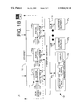
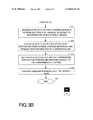
- FIGS. 3A and 3B depict a flowchart of a method 300 that facilitates fault tolerance at a head-end of an interactive information distribution system.
- a normal mode of operation i.e., no failure occurring at the primary head-end controller, is depicted by the flowchart of FIG. 3 .
- a subscriber in an interactive information distribution system starts the method at step 301 , and the method proceeds to step 302 where the subscriber requests video information from their subscriber equipment, i.e., a set-top box.
- the set-top box sends the request through the back channel, to the access system controller dedicated to such set-top box.
- the access system controller receives the subscriber's request and then signals the primary head-end controller to initiate a subscriber session.
- the primary head-end controller initiates the subscriber session through the managing modules that regulate the stream server's video transmissions at the head-end.
- non-distributed managing modules of the primary head-end controller and the distributed managing modules of both the primary and secondary head-end controllers process the session-state data.
- the session-state data is stored on the primary head-end memory and storage devices.
- the memory and storage devices include RAM and either a local or centrally networked disk drive, as depicted in FIGS. 1A and 2A , respectively.
- the session-state data stored on the primary head-end storage devices is replicated, in step 314 , onto the storage devices of the secondary head-end controller, where the storage devices are local to each head-end controller, as depicted in FIGS. 1A and 1B .
- the replication is performed in frequent intervals to provide current session-state data for redundancy purposes in the event of a primary head-end failure.
- the storage device is centrally networked between the primary and secondary head-end controllers as in FIGS. 2A and 2B , then the step 314 is excluded from the routine 300 .
- Step 314 is excluded in this instance since the secondary head-end controller has ubiquitous access to the central storage device that concurrently stores the session-state data created by all the head-end controllers, including the primary head-end controller.
- the plurality of managing modules direct the stream server to retrieve the requested video information from the video content repository and stream the video information to the designated access controller.
- the access controller receives the streamed video information from the server, and then modulates the video information for transmission through the forward channel to the set-top box of the subscriber.
- the primary head-end controller continues to manage the subscriber's session at step 320 , until the session ends, in step 322 .
- FIG. 4 depicts a flowchart of a method for continuing a subscriber session during a failure mode of operation at a head-end controller.
- a failure mode of operation a failure occurs at the primary head-end controller designated to facilitate a subscriber session.
- the secondary head-end controller retrieves the processed session-state data from the fixed storage device and memory of the primary head-end controller in order to continue the subscriber session.
- the failure mode of operation begins at step 401 and proceeds to step 402 , where a failure occurs at the primary head-end controller.
- the failure is detected in an interrupt driven manner from the dedicated access controller previously interfacing with the primary head-end controller.
- the access controller contacts the secondary head-end controller to continue the subscriber's video session.
- the routine 400 proceeds to step 406 where the managing modules of the secondary head-end controller retrieve the latest session-state data available from the primary head-end controller.
- the data is stored in either the memory and storage devices of the primary head-end controller shown in FIGS. 1A and 1B , or the centrally networked storage device shown in FIGS. 2 and 2B .
- both the non-distributed and distributed managing modules of the secondary head-end process the recovered session-state data. In this manner, there is minimal interruption to the subscriber's video session.
- the secondary head-end controller continues the subscriber's session and stores the session-state data on the memory and storage devices of the secondary head-end controller.
- the managing modules continue to direct the stream server to retrieve the requested video information from the video content repository, and stream the video information to the access controller designated to the subscriber.
- the access controller receives the streamed video information from the server and modulates the video information for transmission through the forward information channel, to the set-top box of the subscriber.
- the secondary head-end controller continues to manage the subscriber's session in step 414 , until the session ends, at step 416 .
- fault tolerance is achieved by adding additional head-end controllers to each head-end. This allows for the replicating of processed information onto the memory and storage devices of the secondary head-end controller.
- a subscriber using this improved fault tolerant system will be ensured minimal disruptions to their viewing requirements.
- the implementation of load sharing between two or more head-end controllers decreases the processing time, increases the availability of video information and allows for greater expansion of viewership.
Abstract
Description
Claims (20)
Priority Applications (3)
| Application Number | Priority Date | Filing Date | Title |
|---|---|---|---|
| US09/458,897 US8024761B1 (en) | 1999-04-01 | 1999-12-10 | Method and apparatus of load sharing and fault tolerance in an interactive video distribution system |
| PCT/US2000/008413 WO2000060866A1 (en) | 1999-04-01 | 2000-03-30 | Video distribution system with load sharing and fault tolerance |
| AU40483/00A AU4048300A (en) | 1999-04-01 | 2000-03-30 | Video distribution system with load sharing and fault tolerance |
Applications Claiming Priority (2)
| Application Number | Priority Date | Filing Date | Title |
|---|---|---|---|
| US12733799P | 1999-04-01 | 1999-04-01 | |
| US09/458,897 US8024761B1 (en) | 1999-04-01 | 1999-12-10 | Method and apparatus of load sharing and fault tolerance in an interactive video distribution system |
Publications (1)
| Publication Number | Publication Date |
|---|---|
| US8024761B1 true US8024761B1 (en) | 2011-09-20 |
Family
ID=26825550
Family Applications (1)
| Application Number | Title | Priority Date | Filing Date |
|---|---|---|---|
| US09/458,897 Expired - Fee Related US8024761B1 (en) | 1999-04-01 | 1999-12-10 | Method and apparatus of load sharing and fault tolerance in an interactive video distribution system |
Country Status (3)
| Country | Link |
|---|---|
| US (1) | US8024761B1 (en) |
| AU (1) | AU4048300A (en) |
| WO (1) | WO2000060866A1 (en) |
Cited By (2)
| Publication number | Priority date | Publication date | Assignee | Title |
|---|---|---|---|---|
| US20120173649A1 (en) * | 2001-02-08 | 2012-07-05 | Core Wireless S.A.R.L. | Multimedia messaging method and system |
| US9317440B2 (en) | 2012-07-26 | 2016-04-19 | Samsung Electronics Co., Ltd. | Computing device and virtual device control method for controlling virtual device by computing system |
Families Citing this family (2)
| Publication number | Priority date | Publication date | Assignee | Title |
|---|---|---|---|---|
| WO2003013134A1 (en) * | 2001-07-19 | 2003-02-13 | Klotz Digital Ag | Device for secure, cost-effective downloading of audio and video data |
| EP1788774A1 (en) * | 2005-11-18 | 2007-05-23 | Alcatel Lucent | Method and system for initiating or recovering a media-on-demand session |
Citations (25)
| Publication number | Priority date | Publication date | Assignee | Title |
|---|---|---|---|---|
| US4700348A (en) * | 1984-05-31 | 1987-10-13 | Nec Corporation | Hot standby communications system |
| US5155845A (en) * | 1990-06-15 | 1992-10-13 | Storage Technology Corporation | Data storage system for providing redundant copies of data on different disk drives |
| US5371852A (en) * | 1992-10-14 | 1994-12-06 | International Business Machines Corporation | Method and apparatus for making a cluster of computers appear as a single host on a network |
| US5479396A (en) * | 1993-09-07 | 1995-12-26 | Nec Corporation | Redundant system having signal path operation function |
| US5646676A (en) * | 1995-05-30 | 1997-07-08 | International Business Machines Corporation | Scalable interactive multimedia server system for providing on demand data |
| US5774668A (en) * | 1995-06-07 | 1998-06-30 | Microsoft Corporation | System for on-line service in which gateway computer uses service map which includes loading condition of servers broadcasted by application servers for load balancing |
| US5790176A (en) * | 1992-07-08 | 1998-08-04 | Bell Atlantic Network Services, Inc. | Media server for supplying video and multi-media data over the public switched telephone network |
| US5812748A (en) * | 1993-06-23 | 1998-09-22 | Vinca Corporation | Method for improving recovery performance from hardware and software errors in a fault-tolerant computer system |
| US5815194A (en) * | 1995-02-09 | 1998-09-29 | Nec Corporation | Video-on-demand system |
| US5845328A (en) * | 1995-12-20 | 1998-12-01 | Hitachi, Ltd. | Method for ensuring data coherency for redundat storage by transferring copies of access requests from on-line storage to back-up storage |
| US5862312A (en) * | 1995-10-24 | 1999-01-19 | Seachange Technology, Inc. | Loosely coupled mass storage computer cluster |
| US5892910A (en) * | 1995-02-28 | 1999-04-06 | General Instrument Corporation | CATV communication system for changing first protocol syntax processor which processes data of first format to second protocol syntax processor processes data of second format |
| US5892915A (en) * | 1997-04-25 | 1999-04-06 | Emc Corporation | System having client sending edit commands to server during transmission of continuous media from one clip in play list for editing the play list |
| US5918017A (en) * | 1996-08-23 | 1999-06-29 | Internatioinal Business Machines Corp. | System and method for providing dynamically alterable computer clusters for message routing |
| US5928367A (en) * | 1995-01-06 | 1999-07-27 | Hewlett-Packard Company | Mirrored memory dual controller disk storage system |
| US5978381A (en) * | 1997-06-06 | 1999-11-02 | Webtv Networks, Inc. | Transmitting high bandwidth network content on a low bandwidth communications channel during off peak hours |
| US6002687A (en) | 1996-01-02 | 1999-12-14 | Divicon, Inc. | MPEG transport stream remultiplexer |
| US6195680B1 (en) * | 1998-07-23 | 2001-02-27 | International Business Machines Corporation | Client-based dynamic switching of streaming servers for fault-tolerance and load balancing |
| US6240555B1 (en) * | 1996-03-29 | 2001-05-29 | Microsoft Corporation | Interactive entertainment system for presenting supplemental interactive content together with continuous video programs |
| US6371852B1 (en) * | 1998-04-28 | 2002-04-16 | Acres Gaming Incorporated | Method for crediting a player of an electronic gaming device |
| US6378129B1 (en) * | 1998-03-30 | 2002-04-23 | International Business Machines Corporation | Video server content synchronization |
| US6418557B1 (en) * | 1998-02-06 | 2002-07-09 | Nec Corporation | On-demand system enabling control of power-on/off of on-demand server |
| US6480551B1 (en) * | 1997-11-18 | 2002-11-12 | Sony Corporation | Signal processing device and method for switching signal processors thereof |
| US20030204852A1 (en) * | 1998-12-31 | 2003-10-30 | Baker Botts Llp | Menuing system for controlling content delivery within a video distribution system |
| US6782416B2 (en) * | 2001-01-12 | 2004-08-24 | Hewlett-Packard Development Company, L.P. | Distributed and geographically dispersed quorum resource disks |
-
1999
- 1999-12-10 US US09/458,897 patent/US8024761B1/en not_active Expired - Fee Related
-
2000
- 2000-03-30 WO PCT/US2000/008413 patent/WO2000060866A1/en active Application Filing
- 2000-03-30 AU AU40483/00A patent/AU4048300A/en not_active Abandoned
Patent Citations (25)
| Publication number | Priority date | Publication date | Assignee | Title |
|---|---|---|---|---|
| US4700348A (en) * | 1984-05-31 | 1987-10-13 | Nec Corporation | Hot standby communications system |
| US5155845A (en) * | 1990-06-15 | 1992-10-13 | Storage Technology Corporation | Data storage system for providing redundant copies of data on different disk drives |
| US5790176A (en) * | 1992-07-08 | 1998-08-04 | Bell Atlantic Network Services, Inc. | Media server for supplying video and multi-media data over the public switched telephone network |
| US5371852A (en) * | 1992-10-14 | 1994-12-06 | International Business Machines Corporation | Method and apparatus for making a cluster of computers appear as a single host on a network |
| US5812748A (en) * | 1993-06-23 | 1998-09-22 | Vinca Corporation | Method for improving recovery performance from hardware and software errors in a fault-tolerant computer system |
| US5479396A (en) * | 1993-09-07 | 1995-12-26 | Nec Corporation | Redundant system having signal path operation function |
| US5928367A (en) * | 1995-01-06 | 1999-07-27 | Hewlett-Packard Company | Mirrored memory dual controller disk storage system |
| US5815194A (en) * | 1995-02-09 | 1998-09-29 | Nec Corporation | Video-on-demand system |
| US5892910A (en) * | 1995-02-28 | 1999-04-06 | General Instrument Corporation | CATV communication system for changing first protocol syntax processor which processes data of first format to second protocol syntax processor processes data of second format |
| US5646676A (en) * | 1995-05-30 | 1997-07-08 | International Business Machines Corporation | Scalable interactive multimedia server system for providing on demand data |
| US5774668A (en) * | 1995-06-07 | 1998-06-30 | Microsoft Corporation | System for on-line service in which gateway computer uses service map which includes loading condition of servers broadcasted by application servers for load balancing |
| US5862312A (en) * | 1995-10-24 | 1999-01-19 | Seachange Technology, Inc. | Loosely coupled mass storage computer cluster |
| US5845328A (en) * | 1995-12-20 | 1998-12-01 | Hitachi, Ltd. | Method for ensuring data coherency for redundat storage by transferring copies of access requests from on-line storage to back-up storage |
| US6002687A (en) | 1996-01-02 | 1999-12-14 | Divicon, Inc. | MPEG transport stream remultiplexer |
| US6240555B1 (en) * | 1996-03-29 | 2001-05-29 | Microsoft Corporation | Interactive entertainment system for presenting supplemental interactive content together with continuous video programs |
| US5918017A (en) * | 1996-08-23 | 1999-06-29 | Internatioinal Business Machines Corp. | System and method for providing dynamically alterable computer clusters for message routing |
| US5892915A (en) * | 1997-04-25 | 1999-04-06 | Emc Corporation | System having client sending edit commands to server during transmission of continuous media from one clip in play list for editing the play list |
| US5978381A (en) * | 1997-06-06 | 1999-11-02 | Webtv Networks, Inc. | Transmitting high bandwidth network content on a low bandwidth communications channel during off peak hours |
| US6480551B1 (en) * | 1997-11-18 | 2002-11-12 | Sony Corporation | Signal processing device and method for switching signal processors thereof |
| US6418557B1 (en) * | 1998-02-06 | 2002-07-09 | Nec Corporation | On-demand system enabling control of power-on/off of on-demand server |
| US6378129B1 (en) * | 1998-03-30 | 2002-04-23 | International Business Machines Corporation | Video server content synchronization |
| US6371852B1 (en) * | 1998-04-28 | 2002-04-16 | Acres Gaming Incorporated | Method for crediting a player of an electronic gaming device |
| US6195680B1 (en) * | 1998-07-23 | 2001-02-27 | International Business Machines Corporation | Client-based dynamic switching of streaming servers for fault-tolerance and load balancing |
| US20030204852A1 (en) * | 1998-12-31 | 2003-10-30 | Baker Botts Llp | Menuing system for controlling content delivery within a video distribution system |
| US6782416B2 (en) * | 2001-01-12 | 2004-08-24 | Hewlett-Packard Development Company, L.P. | Distributed and geographically dispersed quorum resource disks |
Cited By (2)
| Publication number | Priority date | Publication date | Assignee | Title |
|---|---|---|---|---|
| US20120173649A1 (en) * | 2001-02-08 | 2012-07-05 | Core Wireless S.A.R.L. | Multimedia messaging method and system |
| US9317440B2 (en) | 2012-07-26 | 2016-04-19 | Samsung Electronics Co., Ltd. | Computing device and virtual device control method for controlling virtual device by computing system |
Also Published As
| Publication number | Publication date |
|---|---|
| WO2000060866A1 (en) | 2000-10-12 |
| AU4048300A (en) | 2000-10-23 |
Similar Documents
| Publication | Publication Date | Title |
|---|---|---|
| US6166730A (en) | System for interactively distributing information services | |
| US8683508B2 (en) | System for interactively distributing information services using randomization | |
| US9813745B2 (en) | Method and apparatus for hierarchical distribution of video content for an interactive information distribution system | |
| US6305019B1 (en) | System for interactively distributing information services having a remote video session manager | |
| US7086077B2 (en) | Service rate change method and apparatus | |
| US20020154892A1 (en) | System for distributing video and content on demand | |
| US20020059619A1 (en) | Hybrid central/distributed VOD system with tiered content structure | |
| US7069575B1 (en) | System for interactively distributing information services | |
| EP1205073A1 (en) | Vod from a server or a user to another user | |
| EP0843937A1 (en) | Data processing system | |
| JP2005512361A (en) | Quality control of stream content delivery | |
| US11064239B1 (en) | Digital video recording with remote storage | |
| US20020073172A1 (en) | Method and apparatus for storing content within a video on demand environment | |
| US8024761B1 (en) | Method and apparatus of load sharing and fault tolerance in an interactive video distribution system | |
| US8739230B2 (en) | Manager/remote content architecture | |
| EP1175776B1 (en) | Video on demand system | |
| US7784079B1 (en) | Video on demand transaction server | |
| CA2574079C (en) | System for interactively distributing information services | |
| Reddy et al. | Video servers | |
| JPH10262235A (en) | Image audio information distribution system | |
| TW201308987A (en) | A multilayer controlling system of data transfer and the method using thereof |
Legal Events
| Date | Code | Title | Description |
|---|---|---|---|
| AS | Assignment |
Owner name: DIVA SYSTEMS CORPORATION, CALIFORNIA Free format text: ASSIGNMENT OF ASSIGNORS INTEREST;ASSIGNOR:GIAMMARRESI, TOM;REEL/FRAME:010479/0018 Effective date: 19991206 |
|
| AS | Assignment |
Owner name: TVGATEWAY, LLC, PENNSYLVANIA Free format text: ASSIGNMENT OF ASSIGNORS INTEREST;ASSIGNOR:DIVA SYSTEMS CORPORATION BY HOWARD B. GROBSTEIN, CHAPTER 11 TRUSTEE;REEL/FRAME:014567/0512 Effective date: 20040421 |
|
| AS | Assignment |
Owner name: SEDNA PATENT SERVICES, LLC, PENNSYLVANIA Free format text: CHANGE OF NAME;ASSIGNOR:TVGATEWAY, LLC;REEL/FRAME:015177/0980 Effective date: 20040824 |
|
| AS | Assignment |
Owner name: COX COMMUNICATIONS, INC., GEORGIA Free format text: ASSIGNMENT OF ASSIGNORS INTEREST;ASSIGNOR:SEDNA PATENT SERVICES, LLC;REEL/FRAME:021817/0486 Effective date: 20080913 |
|
| ZAAA | Notice of allowance and fees due |
Free format text: ORIGINAL CODE: NOA |
|
| ZAAB | Notice of allowance mailed |
Free format text: ORIGINAL CODE: MN/=. |
|
| STCF | Information on status: patent grant |
Free format text: PATENTED CASE |
|
| FPAY | Fee payment |
Year of fee payment: 4 |
|
| MAFP | Maintenance fee payment |
Free format text: PAYMENT OF MAINTENANCE FEE, 8TH YEAR, LARGE ENTITY (ORIGINAL EVENT CODE: M1552); ENTITY STATUS OF PATENT OWNER: LARGE ENTITY Year of fee payment: 8 |
|
| FEPP | Fee payment procedure |
Free format text: MAINTENANCE FEE REMINDER MAILED (ORIGINAL EVENT CODE: REM.); ENTITY STATUS OF PATENT OWNER: LARGE ENTITY |
|
| LAPS | Lapse for failure to pay maintenance fees |
Free format text: PATENT EXPIRED FOR FAILURE TO PAY MAINTENANCE FEES (ORIGINAL EVENT CODE: EXP.); ENTITY STATUS OF PATENT OWNER: LARGE ENTITY |
|
| STCH | Information on status: patent discontinuation |
Free format text: PATENT EXPIRED DUE TO NONPAYMENT OF MAINTENANCE FEES UNDER 37 CFR 1.362 |
|
| FP | Lapsed due to failure to pay maintenance fee |
Effective date: 20230920 |