US8028013B2 - Fast filtering means and filtering and decimation methods - Google Patents
Fast filtering means and filtering and decimation methods Download PDFInfo
- Publication number
- US8028013B2 US8028013B2 US10/591,197 US59119704A US8028013B2 US 8028013 B2 US8028013 B2 US 8028013B2 US 59119704 A US59119704 A US 59119704A US 8028013 B2 US8028013 B2 US 8028013B2
- Authority
- US
- United States
- Prior art keywords
- input signal
- time
- representation
- quantized
- signal
- Prior art date
- Legal status (The legal status is an assumption and is not a legal conclusion. Google has not performed a legal analysis and makes no representation as to the accuracy of the status listed.)
- Expired - Fee Related, expires
Links
Images


Classifications
-
- H—ELECTRICITY
- H03—ELECTRONIC CIRCUITRY
- H03H—IMPEDANCE NETWORKS, e.g. RESONANT CIRCUITS; RESONATORS
- H03H17/00—Networks using digital techniques
- H03H17/02—Frequency selective networks
- H03H17/06—Non-recursive filters
- H03H17/0621—Non-recursive filters with input-sampling frequency and output-delivery frequency which differ, e.g. extrapolation; Anti-aliasing
- H03H17/0635—Non-recursive filters with input-sampling frequency and output-delivery frequency which differ, e.g. extrapolation; Anti-aliasing characterized by the ratio between the input-sampling and output-delivery frequencies
- H03H17/065—Non-recursive filters with input-sampling frequency and output-delivery frequency which differ, e.g. extrapolation; Anti-aliasing characterized by the ratio between the input-sampling and output-delivery frequencies the ratio being integer
- H03H17/0664—Non-recursive filters with input-sampling frequency and output-delivery frequency which differ, e.g. extrapolation; Anti-aliasing characterized by the ratio between the input-sampling and output-delivery frequencies the ratio being integer where the output-delivery frequency is lower than the input sampling frequency, i.e. decimation
-
- H—ELECTRICITY
- H03—ELECTRONIC CIRCUITRY
- H03H—IMPEDANCE NETWORKS, e.g. RESONANT CIRCUITS; RESONATORS
- H03H17/00—Networks using digital techniques
- H03H17/02—Frequency selective networks
- H03H17/0223—Computation saving measures; Accelerating measures
-
- H—ELECTRICITY
- H03—ELECTRONIC CIRCUITRY
- H03H—IMPEDANCE NETWORKS, e.g. RESONANT CIRCUITS; RESONATORS
- H03H17/00—Networks using digital techniques
- H03H17/02—Frequency selective networks
- H03H17/0223—Computation saving measures; Accelerating measures
- H03H17/0225—Measures concerning the multipliers
- H03H17/0226—Measures concerning the multipliers comprising look-up tables
Definitions
- the present invention relates to a hardware implemented filtering method, embodiments of which, among others, comprise fast filtering means in particular fast FIR filtering means and decimation means.
- decimation of a signal without corresponding filtering e.g. anti-aliasing or low-pass filtering
- filtering e.g. anti-aliasing or low-pass filtering
- Conventional FIR-filtering is usually performed by convolving a finite number of impulse response coefficients h[k] of a desired FIR-filter with an equivalent number of samples from the input signal x[n] in order to establish one sample of the output signal y[n]:
- N multiplications and N ⁇ 1 additions have to be made.
- multiplications form a bottleneck and with a FIR filter having a resolution of, e.g., 384 coefficients, i.e. an N of 384, this results in 384 multiplications per sample.
- the sample rate of the input signal is high, e.g. 200 MHz and the filtering is performed on each sample these 384 multiplications should be carried out within less than 5 nanoseconds. This is practically impossible or requires at least extremely expensive and demanding signal processing means.
- the FIR filter to be applied is very complex, e.g. having thousands of coefficients or very high-precision coefficient values it may be almost impossible or at least require excessive processing power
- the present invention relates to a hardware implemented filtering method comprising the steps of
- an advantageous method for filtering an input signal IS whereby the derivative DIS of the input signal is processed rather than the original input signal.
- the method of the present invention may be used for processing any kinds of input signals but its advantages are especially remarkable when there are only few changes of the input signal value over time relative to the sample rate or resolution.
- Such signals are in the following referred to as infrequently changing signals and may, e.g., be characterized by averagely 10, 50 or several hundred samples between each signal value change.
- signals that are typical infrequently changing may, e.g., be mentioned pulse width modulated PWM signals, pulse density modulated PDM signals, and pulse position PPM modulated signals.
- the input signal IS may according to a preferred embodiment be received in a sampled form or the method of the present invention may comprise a step of latching or any other kind of sampling somewhere prior to the step of convolving the input signal derivative with the filter representation.
- the input to the method of the present invention may already be the derivate of an input signal or part of it and the first step of the present invention is then to adapt the input into a representation compatible with the subsequent steps of the present invention. This may, e.g., comprise sampling, re-sampling, modulation or coding scheme conversion, etc.
- the derivative DIS of at least a part of a time-quantized input signal IS is referred to a difference signal established from the input signal, i.e. the equivalent of a differentiated signal in the continuous time domain.
- the method of the present invention not necessarily requires the derivative of the input signal to actually be established but only some kind of representation of it.
- Derivatives of infrequently changing signals comprise, e.g., relatively many zeroes and a beneficial representation of such a derivative is to register only the times where the derivative is non-zero.
- the establishment of the representation DIS of the input signal derivative may be carried out by any suitable method, e.g. by actually establishing the full, mathematically differentiated signal or by only registering changes of the input signal and indexing those or by any other method.
- the filter representation IFC 1 , IFC 2 , IFC 3 or part of it may be established as a set of filter coefficients, one or more filter representing polynomials, or any other way of representing a filter.
- the filter representation may represent a filter in any way, e.g. by its impulse response, its integrated or accumulated impulse response, its differentiated impulse response, or any other direct or indirect constitution of a filter.
- the filtering of the input signal derivative DIS is, preferably, performed by a kind of convolution process that is especially advantageous over a full convolution when the input signal derivative DIS comprises several zeroes, i.e. the input signal IS is an infrequently changing signal.
- the output signal OS is, preferably, of a PCM signal type.
- the filtering method may be hardware implemented e.g. in an integrated circuit, in a programmable logic device (PLD) or programmable gate array (PGA), e.g. a complex programmable logic device (CPLD), an application specific integrated circuit (ASIC), a very large scale integration chip (VLSI-chip), a field programmable gate array (FPGA) etc., in a programmable processor, e.g. a digital signal processor (DSP), central processing unit (CPU), by logic gates and circuitry, as software in a computer, any combination of the above, or in any other suitable way.
- PLD programmable logic device
- PGA programmable gate array
- DSP digital signal processor
- CPU central processing unit
- the present invention further relates to a hardware implemented method of convolving in the time domain an input signal x[n] with an impulse response h[k] in order to establish an output signal y[n], characterised by that said output signal y[n] is provided at least partly by a convolution in the time domain of a difference signal representation x′[n] of said input signal x[n] and a sum representation l[k] of said impulse response h[k].
- an advantageous convolution method is obtained which is particular beneficial for use with infrequently changing input signals as the difference signal established from an infrequently changing signal mostly comprises zeroes.
- the output signal y[n] is, thus, at least partly provided by exercising x′[n]*l[k]
- the sum representation l[k] relates to the impulse response h[k] in a way analogous to the way an integrated signal in the continuous time domain corresponds to the signal it is obtained from and may, e.g., be expressed as:
- the establishment of the difference signal representation and the sum representation may be performed in different ways and at different times. They may, e.g., be established immediately prior to the convolution of the signals or one or both of the signals may be established anytime and anywhere prior to the convolution if that may be more convenient.
- the sum representation of the impulse response is pre-calculated and stored as constants in a table, whereas the difference signal representation derived from the input signal is established when needed.
- the convolution method may be hardware implemented, e.g. in an integrated circuit, in a programmable logic device (PLD) or programmable gate array (PGA), e.g. a complex programmable logic device (CPLD), an application specific integrated circuit (ASIC), a very large scale integration chip (VLSI-chip), a field programmable gate array (FPGA) etc., in a programmable processor, e.g. a digital signal processor (DSP), central processing unit (CPU), by logic gates and circuitry, as software in a computer, any combination of the above, or in any other suitable way.
- PLD programmable logic device
- PGA programmable gate array
- DSP digital signal processor
- CPU central processing unit
- the length of the impulse response is finite. Furthermore, it is, preferably, of a length comparable to the length of one symbol of the input signal IS where symbol here refers to one modulated data value. I.e. when the input signal is a sampled PWM signal with, e.g., 128 samples per PWM period, a symbol is said to have a length of 128 samples and the length of the finite impulse response is, preferably, in the scale of 50-500 samples, e.g. 384 samples.
- the length of the impulse response may, however, according to the invention be anything, e.g. considerably longer for an advanced filter.
- the filtering may be referred to as finite impulse response filtering also referred to as FIR filtering, however by a method more sophisticated than conventionally known FIR filtering.
- infinite impulse responses as basis for the filtering is within the scope of the present invention.
- filtering is also referred to as infinite impulse response filtering or IIR filtering.
- time-quantized input signal IS comprises in average at least 10, preferably at least 64, and even more preferably at least 128 samples for each input signal value change, an advantageous embodiment of the present invention has been obtained.
- the present invention is particularly advantageous when the input signal is an infrequently changing signal and the efficiency and benefit of the method of the present invention is substantially inversely proportional to the amount of changes in the input signal relative to the sample rate.
- the present invention is particularly advantageous as such signals are typically very infrequently changing and often sampled at rates that make conventional filtering very problematic or impossible. Even though the PWM input signal is, furthermore, preferably a two-level PWM signal, the present invention applies to signals and PWM signals of any coding scheme.
- said establishing a representation DIS of the derivative of at least a part of said time-quantized input signal IS comprises the step of establishing a sequence of differences between successive samples of said at least a part of said input signal IS, an advantageous embodiment of the present invention has been obtained.
- the array DA may be implemented in any suitable way, e.g. by means of software or hardware registers, external memory of any kind, an array of variables, etc.
- said establishing a representation DIS of the derivative of at least a part of a time-quantized input signal IS comprises the step of indexing corresponding times and directions of amplitude changes of said at least a part of said input signal IS, an advantageous embodiment of the present invention has been obtained.
- Indexing amplitude changes by time and direction and preferably storing these pairs in a differentiated input signal representing array DA ensures a minimum of needed storage space and, furthermore, simplifies the subsequent processing. Storing only times and directions of changes works, however, only with two-level signals. For signals with more levels, e.g. a three-level PWM signal or a 2-bit PCM signal also the magnitude of each change has to be recorded together with the times and directions, unless the signal is coded in such a way that all changes have the same magnitude.
- time should be understood in a broad sense as it in the present disclosure not strictly corresponds to a measure of seconds or nanoseconds but as well may apply to a measure of a number of samples, whether these are processed in real time or not.
- a symbol represents one modulated data value of the input signal.
- a symbol most often represents one pulse and has a length corresponding to the PWM period length.
- the number of changes within an input signal symbol is fixed. Thereby, it is possible to implement more specifically dedicated change indexing logics.
- the symbol edges are also synchronized with the convolution algorithm, e.g. by having the first and last input samples being used in one convolution be edges of input signal symbols an even simpler and faster change indexing means may be implemented.
- indexing times relative to each other is referred to indexing the time span between each change rather than an absolute time since the first sample.
- a time may refer to a number of samples as well as to a span of seconds or nanoseconds.
- said establishing a representation DIS of the derivative of at least a part of a time-quantized input signal IS comprises the step of storing into a snapshot register SR said at least a part of said time-quantized input signal IS, an advantageous embodiment of the present invention has been obtained.
- a part of the input signal is stored to a snapshot register RS before each convolution.
- that part of the input signal may be processed while the true input signal resumes.
- This is particularly beneficial when only one convolution per several input samples is performed, i.e. in a situation where the filtering method is used for decimation.
- the convolution means and other processing means are allowed to work at a rate corresponding to the rate of the output signal rather than of the input signal.
- said establishing a representation DIS of the derivative of at least a part of a time-quantized input signal IS comprises the step of querying said snapshot register RS regarding input signal changes, an advantageous embodiment of the present invention has been obtained.
- the difference signal representation may be established more or less on demand by querying the snapshot register only when the convolution means are ready for the next value or values.
- storage space is spared together with the otherwise most often needed pre-determination and storing of signal changes.
- the query replies that represent the input signal derivative and these exist, preferably, only for a limited time and a limited part of the signal at a time.
- the filter representation used to convolve with the input difference signal is a sum representation, i.e. the equivalent to an integrated signal representation in the continuous time domain.
- the filter representation preferably the accumulated impulse response
- the filter representation is computed prior to the convolution processing, e.g. by the manufacturer, the user, etc.
- a desired impulse response is usually not required to be changed during a convolution process its sum representation may as well be calculated once beforehand and stored in a more or less fixed way, thereby minimizing the processing needed at runtime.
- the preferably accumulated impulse response is stored as filter coefficients. This is particularly beneficial when the sum representation is predetermined. By storing values in a table, less processing power is needed for the convolution algorithm.
- the length of the filter i.e. the number of filter coefficients, should be short enough for the convolution to be completed within the time at disposal but still long enough for the filter to be sufficiently efficient.
- a model preferably a mathematical model expressed by polynomials, is used for implementing the sum representation.
- a model approach requires more processing power in order at runtime but requires on the other hand only little storage capacity.
- any symmetry of the filter representation e.g. even or odd symmetry, is utilized in order to minimize the storage space or computations needed in order to handle the filter representation.
- the user may change the filter representation, e.g. according to specific uses.
- said performing filtering comprises convolving said at least a part of said filter representation IFC 1 , IFC 2 , IFC 3 with said representation DIS of the derivative of at least a part of said time-quantized input signal IS, an advantageous embodiment of the present invention has been obtained.
- the input signal derivative is convolved with the accumulated impulse response.
- the result of a convolution of the input signal with the impulse response is obtained in a fast and efficient way.
- said performing filtering further comprises for each of said at least one sample of a time- and amplitude-quantized output signal OS adding the result of multiplying an initial value IV of said at least a part of said time-quantized input signal IS with a value of said at least a part of said filter representation IFC 1 , IFC 2 , IFC 3 , an advantageous embodiment of the present invention has been obtained.
- an initial value IV of the current processed part of the input signal IS should be multiplied with the last value of the accumulated impulse response IFC 1 , IFC 2 , IFC 3 and the result hereof added to the result of the convolution.
- said performing filtering further comprises adding, for each of said at least one sample of a time- and amplitude-quantized output signal OS, an initial value IV of said at least a part of said time-quantized input signal IS, an advantageous embodiment of the present invention has been obtained.
- the initial input signal value IV is merely added to the output sample. This is possible in the preferred embodiment where the desired filter has unity DC-gain and thus the last value of the accumulated impulse response is 1.
- the result of the fast filtering method of the present invention is, furthermore, filtered by conventional filtering methods.
- This may be particularly beneficial when the desired overall filter characteristic is possible to divide into a part that may take advantage of the fast filtering method of the present invention and a part that may as well or even better be performed by conventional filtering methods.
- the fast filtering method of the present invention is also used for decimation of the sample rate, conventional filtering may subsequently be performed on the lower rated output.
- the conventional filtering may alternatively comprise integration or any other kind of filtering.
- the output signal is differently rated than the input signal.
- the fast filtering method of the present invention may also serve as, e.g., a decimation method.
- the method of the present invention allows the output signal to be adapted to a specific requirement of subsequent processing steps.
- the input signal is filtered and decimated in order for the output signal to comprise only one sample for each input signal symbol.
- This embodiment is particular advantageous when the fast filtering method of the present invention is used for demodulating a signal requiring a high time resolution, e.g. a PWM-signal, the PWM-pulses, thus, denoting the input signal symbols.
- the output signal is then, typically, of more convenient use when having the sample rate of the input symbols, e.g. the PWM-pulses.
- the convolution process is not performed for every input sample. Thereby, less output samples are established than input samples available, and the output signal is, thus, decimated.
- the decimation factor corresponds to the amount of convolutions relative to the number of input samples. If, e.g., only one convolution is made for every 128 samples, the sample rate of the output signal established is only 1/128 of the input signal's sample rate. If, with the same example, each input signal symbol, e.g. PWM pulses, has a length of 128 input samples, the output signal's sample rate will correspond to the input signal's symbol rate, which is typically also preferred.
- filter representation IFC 1 , IFC 2 , IFC 3 comprises a sum representation of a low-pass filter
- the input signal is low-pass filtered. This is very advantageous when the method is used for decimation, as the input signal then need to be low-pass filtered in order to avoid aliasing. Low-pass filtering also often causes an infrequently changing modulated signal, e.g. a PWM-signal, to be demodulated.
- the method is a real time method and may, thus, be used to filter signals in real time.
- an advantageous method for use in, e.g., real time audio applications or other real time applications is provided.
- real time is interpreted in a broad sense, thus also covering more realistic applications where the filtering is in fact performed at a rate keeping up with the input signal but where the processing, however, constitutes a small or longer delay.
- the filter representation on the basis of which the derivative of the input signal is filtered is the impulse response of a desired filter characteristic and thereby not an accumulated impulse response.
- the output signal should, preferably, be integrated in order to provide the desired result.
- the filter representation on the basis of which the derivative of the input signal is filtered is the derivative of the impulse response of a desired filter characteristic and is, thereby, not an accumulated impulse response.
- the output signal should, preferably, be integrated twice in order to provide the desired result.
- the hardware implemented filtering method mentioned above further comprises the step of integrating at least once said time- and amplitude-quantized output signal OS, an advantageous embodiment of the present invention has been obtained.
- the output signal is integrated either in the discrete-time domain or, subsequent to any digital-to-analogue conversion, in the continuous-time domain.
- This integration is beneficial when the filter representation is not an integrated impulse response of a filter.
- the integration may need to be performed twice or more according to the amount of differentiation and integration previously performed on the input signal and filter representation.
- the integration may be performed by any integration means, e.g. digitally or analogue, and by any variant of integration, e.g. also by so-called leaky integration.
- the present invention further relates to a decimation method for decimating a time-quantized input signal IS comprising the steps of
- a decimation method comprising filtering, e.g. anti-alias filtering and usable on signals with high sample rates.
- the decimation method of the present invention is particularly advantageous when used on infrequently changing input signals.
- Some degree of anti-aliasing has to be applied to properly decimate the input signal and this may advantageously be done by means of the filtering method of the present invention.
- the method of the present invention should not necessarily be carried out continuously with the input signal but rather at certain intervals. These intervals should, preferably, be of equal length but may in certain applications be irregular.
- the resulting decimation factor is 1, i.e. the output signal is of the same rate as the input signal.
- the resulting decimation factors are correspondingly 2, 10 and 128, i.e. the sample rate of the output signal is a half, a 1/10 or a 1/128 of the input sample rate.
- the decimation method of the present invention is particularly advantageously used within applications where a sub-circuit needs a signal to have a very high sample rate.
- the output In order for the output to be used in other parts of the application, it needs to be decimated. This may, e.g., occur where an analogue signal comprising time-sensitive modulated information is sampled by means of a fast A/D-converter in order to process the signal by digital means.
- the signal When the signal is processed it may be decimated and possibly also demodulated before sent to the next stage.
- the present invention further relates to a fast filtering means FFM comprising
- an advantageous filtering means for performing fast filtering, preferably fast FIR filtering, of time-quantized input signals, preferably infrequently changing signals, e.g. PWM-signals.
- the fast filtering means FFM implements the hardware implemented filtering method or hardware implemented method of convolving an input signal with an impulse response or the hardware implemented decimation method mentioned above, an advantageous embodiment of the present invention has been obtained.
- FIG. 1 illustrates a conceptual block diagram of the present invention
- FIG. 2 illustrates an example of an infrequently changing input signal
- FIG. 3 illustrates a difference signal derived from the signal of FIG. 2 .
- FIG. 4 illustrates one method of establishing a differentiated input signal DIS
- FIG. 5 illustrates examples of a differentiated input signal representing array DA
- FIG. 6 illustrates an alternative method of establishing a differentiated input signal
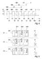
- FIG. 7 illustrates examples of a snapshot register SR
- FIG. 8 illustrates examples of filter coefficients
- FIG. 9 illustrates examples of integrated filter coefficients
- FIG. 10 illustrates the efficiency of a preferred filter characteristic
- FIG. 11 illustrates an application where the present invention may be used.
- FIG. 12 illustrates a further application where the present invention may be used.
- FIG. 2 which comprises a vertical axis for indicating the value of an input signal x[n] and a horizontal axis for indicating samples n of the input signal.
- the signal x[n] of this example comprises a pulse width modulated signal (also referred to as a PWM signal) having a period length of 128 samples as indicated by the dashed vertical lines.
- the PWM signal is characterized by only changing its value twice per period and as its information is represented by the times where the signal changes, a high sample rate is necessary in order to convey high resolution information.
- the sampled PWM signal may, thus, be considered having content that is infrequently changing relative to the sample rate, i.e. twice per, e.g., 128 samples.
- sampled signals with relatively infrequently changing content may comprise signals modulated by different varieties of the PWM technique, e.g. uniform PWM (UPWM), natural PWM (NPWM) and linearized PWM (LPWM), two- and three-level single sided (UADS and UBDS) and two- and three-level double sided (UADD and UBDD) PWM modulation schemes, pulse density modulated signals (also referred to as PDM signals) of different kinds, pulse position modulated signals (also referred to as PPM signals) of different kinds, over-sampled signals of different kinds, etc.
- the signals may have any bit-width, e.g. 1 bit for a most simple PWM or PDM signal, 2 bit for a three- or four-level PWM signal, etc.
- the present invention provides a method for performing filtering, preferably finite impulse response filtering (also referred to as FIR filtering), which is especially advantageous when processing signals having content that is infrequently changing relative to the sample rate.
- filtering preferably finite impulse response filtering (also referred to as FIR filtering)
- FIR filtering finite impulse response filtering
- the fast filtering method of a preferred embodiment of the present invention utilizes that the difference signal of an infrequently changing signal becomes zero except for the few times where the original signal changes.
- FIG. 3 illustrates the same axes as in FIG. 2 , except for the change of density of the vertical axis.
- the difference signal of FIG. 3 assumes the value 2, i.e. 1 ⁇ ( ⁇ 1), and where the PWM signal changes from 1 to ⁇ 1 the difference signal assumes the value ⁇ 2, i.e. ( ⁇ 1) ⁇ 1.
- the difference signal takes the value zero for most of the samples.
- conventional FIR-filtering is usually performed by convolving a finite number of impulse response coefficients h[k] of a desired FIR-filter with an equivalent number of samples from the input signal x[n] in order to establish one sample of the output signal y[n]:
- the registers of some processing means must be loaded N times with N possibly different values and N multiplications and N ⁇ 1 additions usually have to be made. If the values, i.e. the signal values, the impulse response coefficients or both, are high resolution values the multiplications and/or additions may, depending on the particular hard- and software capabilities, have to be carried out, e.g. twice for each value for the most significant half and the least significant half, respectively.
- the finite impulse response coefficients have to be adapted in order to obtain the same resulting output signal as with conventional convolution techniques.
- the filter coefficients to convolve with the difference signal x′[n] should ensure that the resulting signal is equal to the signal y[n] established by convolving the original filter coefficients h[k] with the original input signal x[n]. It can be shown that establishing a sum signal l[k] on the basis of the original filter coefficients h[k] may almost match that criterion, with only an initial value missing.
- x is a time-quantized input signal
- h is a time-quantized filter impulse response of length N
- y is a time-quantized output signal.
- the integral l of the FIR filter impulse response h may in the discrete time domain be written as a sum:
- w ⁇ [ n ] x ⁇ [ n ] ⁇ h ⁇ [ 0 ] + x ⁇ [ n - 1 ] ⁇ ( - h ⁇ [ 0 ] + h ⁇ [ 0 ] + h ⁇ [ 1 ] ) + x ⁇ [ n - 2 ] ⁇ ( - h ⁇ [ 0 ] - h ⁇ [ 1 ] + h ⁇ [ 0 ] + h ⁇ [ 1 ] + h ⁇ [ 2 ] ) + x ⁇ [ n - 3 ] ⁇ ( - h ⁇ [ 0 ] - h ⁇ [ 1 ] - h ⁇ [ 2 ] + h ⁇ [ 0 ] + h ⁇ [ 1 ] + h ⁇ [ 2 ] + h ⁇ [ 3 ] ... + ⁇ x ⁇ [ n - ( N - 2 ) ]
- y[n] may be expressed as:
- y[n] may be obtained by convolving the difference signal of the input signal with the sum of the first N ⁇ 1 samples of the N-length FIR filter impulse response and thereto adding the product of multiplying the accumulated all N samples of the impulse response with a further sample of the original input signal x[n].
- the DC-gain of the FIR filter is unity. This is achieved by scaling the impulse response coefficients of the FIR filter so that their overall sum equals 1.
- x[n ⁇ (N ⁇ 1)] is the oldest sample of the processed part of the original signal.
- x′[n] and l[n] may be determined before the FIR filtering, it is known which samples of x′[n] that are zero. This knowledge may be used for only calculating the products of the convolution where x′[n] ⁇ 0. For slow-varying signals only few samples of x′[n] are non-zero and thus the number of multiplications and additions to carry out is significantly reduced.
- FIG. 1 illustrates conceptually an embodiment of the present invention. It comprises an input signal IS coupled to a differentiation means DM. From the differentiation means DM is output two signals, a difference input signal DIS and an initial value signal IV. Both signals are coupled to a filtering means FM, which establishes an output signal OS.
- a differentiation means DM From the differentiation means DM is output two signals, a difference input signal DIS and an initial value signal IV. Both signals are coupled to a filtering means FM, which establishes an output signal OS.
- the input signal IS may be any kind of sampled signal but is preferably a sampled signal with infrequently changing content, e.g. a PWM signal such as the signal x[n] illustrated in FIG. 2 .
- the differentiation means DM is a means adapted for deriving from the input signal IS a difference input signal DIS such as the signal x′[n] illustrated in FIG. 3 .
- the differentiation means DM further establishes an initial value signal IV, representing the first sample of the part of the input signal IS currently being processed. As shown during the above reasoning, this value referred to as x[n ⁇ (N ⁇ 1)] is necessary in order to establish a final result equal to the conventional and heavy convolution of the immediate input signal.
- the filtering means FM is adapted to perform convolution of the difference input signal DIS, also referred to as x′[n], with a set of filter coefficients, in the above reasoning referred to as l[k].
- the output signal OS is established on the basis of the result of the convolution and the initial value IV.
- the output signal is, preferably, a pulse code modulated signal, i.e. a PCM signal.
- An advanced preferred embodiment of the present invention further facilitates the rate of the output signal OS to be different, preferably to the lower, from the rate of the input signal IS.
- This is an advantageous feature, as the output signal may then be adapted to match any subsequent processing means or be suited for comparison with a certain other signal.
- the signal rates are often increased in order to facilitate broadband processing but should subsequently be reduced in order to minimize unnecessary overhead in order to match the subsequent steps or certain standards, or in order to facilitate transmission by standard transmission means or over long distances.
- the filtering means FM may, further, comprise additional filtering means, e.g. conventional filters to be applied subsequently to the convolution described above.
- additional filtering means e.g. conventional filters to be applied subsequently to the convolution described above.
- the above-described sophisticated filtering and decimation method is used for filtering and decimating the rate of the input signal only from, e.g., 512 times the desired rate to, e.g., 4 times the desired rate, whereupon the rate may be slow enough to enable conventional, possibly more advanced, filters, before decimating the last, e.g., 4 times.
- the filtering means FM may further comprise means for integrating the output of the convolution. This may be particularly useful when the filter coefficients or filter model are/is not an integrated representation of the desired filter.
- the integration may comprise any integration means, e.g. digital or analogue, true integrators or leaky integrators, etc.
- the present invention may be implemented in several different ways. Some possible implementations follow very well the conceptual diagram of FIG. 1 , whereas others appear as a more integrated whole.
- the differentiation means DM is adapted to index the time and direction of any changes in the input signal IS. From a dynamic array comprising such times and directions established by the differentiation means; it would be possible to establish the differentiated or difference signal and such an array may, thus, be regarded as a representation of the difference input signal DIS.
- the example is based on a two-level PWM input signal IS capable of representing the values 0 and 1 and a filter having an impulse response of length 384.
- the horizontal axis represents the sample count n, divided into blocks of 128 samples.
- the sample count axis also represents the time. The samples are divided this way due to a desired rate decimation of 128 times in this example. Calculating only one output sample for each 128 input samples is an advantageous way of obtaining the decimation and thus a division of the input signal into blocks of 128 is meaningful but, however, not necessary.
- the sample count n the value 0 at all times represents the newest sample and thus negative counts represents older samples.
- the sample with the number ⁇ 767 is the oldest sample illustrated in FIG. 4 .
- indexes representing upward input signal changes IU and downward input signal changes ID are shown under the horizontal axis.
- the indexes are offsets according to the block of 128 samples they belong to.
- the logic that actually detects the changes and records the time or count where they occur may be any suitable hardware or software implementation. To a person skilled in the art several well-known solutions to this step exist.
- a change indexer may read the input signal into a so-called first-in-first-out (FIFO) buffer sized for two samples.
- FIFO first-in-first-out
- a counter keeps track of the number of received samples.
- the counter may reset or turn over each 128 samples, thus being at least a 7-bit counter.
- a FIR filtering of length 384 samples is wanted.
- the difference input signal representation DIS should, thus, at least be able to provide information about 384 samples. This may be obtained in several ways.
- an array comprising the indexes of the upward and downward changes may be established.
- An example of such an array DA is illustrated in FIG. 5 at three different time stages, C 1 , C 2 and C 3 , each corresponding an output sample computation.
- 384 samples cover exactly 3 blocks of 128 samples, it comprises three array parts, AP 1 , AP 2 , and AP 3 .
- the first array part AP 1 corresponds to the first 128 samples of the signal illustrated in FIG. 4 , i.e.
- the second array part AP 2 corresponds to the next 128 samples, i.e. samples ⁇ 639 through ⁇ 512
- the third array part AP 3 corresponds to the next 128 samples, i.e. samples ⁇ 511 through ⁇ 384.
- a first column of the difference input signal representing array DA holds directional information of the change where a “+” represents an upward change and a “ ⁇ ” represents a downward change.
- a second column holds timing information of the change, i.e. the index offsets IU and ID.
- the indexes of the first array part AP 1 should be added to an offset of ⁇ 383
- the indexes of the second array part AP 2 should be added to an offset of ⁇ 255
- the indexes of the third array part AP 3 should be added to an offset of ⁇ 127.
- the indexes of the first array part AP 1 should be subtracted from and offset of 383, the indexes of the second array part AP 2 from an offset of 255, and the indexes of the third array part AP 3 from an offset of 127 as the filter coefficients have indexes in the range 0 to 383.
- the difference input signal representing array DA is in FIG. 5 illustrated at three different times.
- the array is illustrated as it would look with the input signal of FIG. 4 at each of the first three output sample computations C 1 , C 2 and C 3 .
- the indexes stored in the second and third array parts AP 2 , AP 3 may be left unchanged when initializing the next output sample computation and just moved to the preceding array part, i.e. AP 1 and AP 2 . This is illustrated by use of arrows in FIG. 5 .
- the indexes may as well be left unmoved, and pointers to the array parts rather be modified from pointing to AP 2 and AP 3 into pointing to AP 1 and AP 2 .
- relative indexes may be stored, i.e. the number of samples between each change.
- the first array part AP 1 of FIG. 5 would comprise the values 14 (from 14 ⁇ 0) and 47 (from 61 ⁇ 14), the second array part the values 82 (from 128+15 ⁇ 61), 63 (from 78 ⁇ 15) and 41, and the third array part the values 56 and 34.
- the difference input signal representing array DA may be implemented in any suitable way.
- the maximum index is 127 it would be beneficial to store each index as a 1-byte signed integer, thus letting the sign represent the change direction, or alternatively as a 7-bit unsigned integer, reserving a separate bit for indicating the direction.
- the differentiated input signal representation needs to be capable of storing information about the magnitude of each change.
- a three-level signal providing, e.g., the levels ⁇ 1, 0 and 1, change magnitudes of 0, 1 and 2 levels may occur.
- the change magnitude may, e.g., be stored together with the direction information as a signed integer. If the input samples are compared by subtraction, both the direction and the magnitude are automatically comprised by the result.
- the differentiation means DM should also establish an initial value signal IV.
- the initial value should be the value of the oldest of the 384 samples of the input signal IS which difference signal is currently represented by the array DA, i.e. the sample with the absolute index of ⁇ 383.
- the content of the initial value signal IV is illustrated in FIG. 5 for each of first three output sample computations C 1 , C 2 and C 3 . In the example of FIGS.
- the initial value is thus 0 for the first computation C 1 comprising samples ⁇ 767 through ⁇ 384 because sample ⁇ 767 is 0, also 0 for the second computation C 2 comprising samples ⁇ 639 through ⁇ 256 because sample ⁇ 639 is 0, and 1 for the third computation C 3 comprising samples ⁇ 511 through ⁇ 128 because sample ⁇ 511 is 1.
- the differentiated input signal DIS is not established for a whole output sample computation at a time as in the above-described embodiment but rather provides an output from which the differentiated input signal DIS may easily be derived on demand, i.e. as needed by the subsequent filtering means FM. Such an embodiment is described below with reference to FIG. 6 .
- FIG. 6 comprises the same example input signal IS as is illustrated in FIG. 4 and for the description of this embodiment the same example values is assumed as with the previous embodiment, i.e. a two-level PWM input signal, a filter length of 384 samples and a decimation factor of 128.
- the differentiation means comprises a first-in-first-out (FIFO) input buffer IB.
- the input signal IS is fed to this buffer and for each new sample arrival, the oldest sample in the input buffer is discarded.
- FIG. 6 illustrates the input buffer at three different times, i.e.
- the input buffer thus acts like a window of a certain width, corresponding to the filter length, behind which the input signal passes.
- the differentiation means in this embodiment comprises a snapshot register SR.
- the size of this register is preferably the same as the size of the input buffer IB, i.e. 384 samples in this example.
- the current content of the input buffer IB is copied to the snapshot register SR.
- the content of the snapshot register is only changed every e.g. 128 samples.
- FIG. 7 illustrates examples of the content of the snapshot register SR at the three above mentioned times.
- the content of the input buffer referred to as IBC 1
- IBC 1 the content of the input buffer
- IBC 2 the snapshot register SR
- IBC 2 The current content of the input buffer
- the samples in the snapshot register may as well be renumbered, e.g. as 0 through 383 in the present example. This numbering is in FIG. 7 referred to as a snapshot register count SRC.
- the snapshot register may be divided into a number of register parts analogous to the division of the differentiated input signal representing array DA into array parts AP 1 , AP 2 and AP 3 in the above-described embodiment of a differentiation means.
- a certain register part may, thus, imply a certain offset to add to the register sample counts in order to distinguish samples from different register parts.
- the snapshot register SR does not represent the differentiated input signal DIS but merely a snapshot of the input signal. That snapshot is, however, very useful as it for a relatively long time, i.e. 128 samples in the present example, provides access to an otherwise vanished part of the input signal. Consequently, it is possible for any subsequent circuitry or logic to process the input signal according to their own timing schemes and rate capabilities and it is possible to perform processing that requires a certain memory of otherwise past input samples.
- the filtering means FM is, thus, able to repeatedly query the snapshot register in order to obtain information about changes in the input signal instead of requiring an array with those changes furnished before the filtering process begins. The difference signal is, thus, never actually established in the present embodiment but rather calculated value by value on demand.
- any suitable circuitry or logic may be used, e.g. as described above with reference to the previous embodiment. Also the above notes about use of three or more level input signals, e.g. three level PWM signals, apply to the present embodiment.
- the initial value signal IV may in the present embodiment be established exactly as with the above-described embodiment and thus stored in a separate register referred to as IV in FIG. 5 .
- the initial value IV may, however, alternatively be derived from the snapshot register SR as that register comprises the real input signal values.
- a differentiation means DM also uses an input buffer IB as described above with reference to FIG. 6 and a snapshot register SR as described above with reference to FIG. 7 .
- the filtering means FM or any other subsequent circuitry need not query the snapshot register SR in order to determine the time of changes in the input signal.
- a system of preferably logic gates and multiplexers, alternatively software or other means is coupled to the snapshot register in order to establish a representation of the input signal changes that may be readily used by the filtering means FM.
- the number of changes within the part of the input signal currently stored in the snapshot register is preferably known and even more preferably the position of each change is known to be within certain limits.
- input signals comprising a specific number of changes within a specific number of samples.
- Such a signal may, e.g., be a two-leveldouble-sided PWM signal (UADD) with a fixed PWM-period, thus comprising one change upwards in the first half of each period and one change downward in the second half of each period.
- UADD two-leveldouble-sided PWM signal
- the length of snapshot register is an integer multiple of PWM periods and the PWM periods are synchronized such that the first sample of a period becomes the first sample of the snapshot register
- the approximate position of each change in the snapshot register is known.
- the snapshot register comprises three PWM periods starting from the first sample, there will be one upward change among the first 1 ⁇ 6 of the samples, one downward change among the second 1 ⁇ 6 of the samples, etc.
- By means of relatively simple logics it may, thus, be possible to establish directly the position of each change and, e.g., use these positions as look-up addresses for extracting filter coefficients from a table within the filtering means FM.
- addresses representing the 6 changes may easily be established by means of logic gates and multiplexers.
- a differentiation means DM that establishes or provides easy access to deriving a differentiated input signal DIS and a corresponding initial value IV is within the scope of the present invention.
- the filtering means FM of the present invention may be embodied in several different ways as well. As described above, the filtering means should be able to perform a convolution on the basis of a set of filter coefficients and the differentiated input signal DIS and thereto add the product of multiplying a further filter coefficient with the initial value signal IV.
- the filter coefficients to be used are pre-computed and stored in a coefficients table where they are looked up when needed by the filtering means.
- the coefficients may be computed and stored once, e.g., by the manufacturer, or they may be provided possibly at any time by the user or an auxiliary processing means. It is, thus, possible for a user or an artificial intelligence or regulation means to define and reconfigure the filtering according to different needs or requirements.
- the coefficients may be derived by first choosing a desired filter characteristic, then establishing a set of filter coefficients by accumulating the coefficients that would correspond to the desired characteristic if conventional convolution were performed.
- FIG. 8 illustrates three examples of filter characteristics illustrated by the filter coefficients to use with conventional convolution. It comprises a horizontal axis indicating the coefficient number CN, and a vertical axis indicating coefficient values CV.
- a first example of filter coefficients FC 1 marked with circles, represents a 128-point running average finite impulse response (FIR) filter. All coefficients have the same value, i.e. 1/128.
- FIR finite impulse response
- a second example of filter coefficients FC 2 represents a 256-point weighted running average FIR filter. Actually this filter corresponds to two cascaded filters with the characteristic of the above example. It causes also a low-pass filtering with a DC-gain of 1.
- a third, preferred example of filter coefficients FC 3 represents a 384-point weighted running average FIR filter. Actually this filter corresponds to three cascaded filters of the FC 1 characteristic. It also causes a low-pass filtering with a DC-gain of 1.
- FIG. 9 illustrates the integrated filter coefficients IFC 1 , IFC 2 , IFC 3 that should be used as filter coefficients with the filtering means FM of the present invention in order to realize the filter characteristics of the examples of FIG. 8 .
- the integrated filter coefficients IFC 1 should be used, and accordingly the integrated filter coefficients IFC 2 for obtaining the filter of the coefficients FC 2 , and the integrated filter coefficients IFC 3 for obtaining the filter of the coefficients FC 3 .
- the integrated filter coefficients are computed simply by accumulating the filter coefficients of the examples of FIG. 8 . As all filter examples have a DC-gain of 1, the last integrated filter coefficient of each filter have a coefficient value of 1.
- the computed filter coefficients may e.g. be stored in a look-up table for use with the convolution process.
- the size needed for storage of the integrated coefficients is bigger than needed for storage of the original coefficients, as the bit-width of each coefficient may be larger.
- the second half of a coefficient set may be derived from the first half, e.g. by subtracting the coefficient values from 1. Thereby, in order to save storage space, it is only necessary to store the first half of a certain coefficient set, and derive coefficients from the second half when needed. This odd symmetry is however not true for all possible filter characteristics that may be used with the present invention.
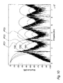
- FIG. 10 illustrates the effect of the three filter examples of FIGS. 8 and 9 . It comprises a frequency spectrum of an example PWM signal.
- the signal is a two-level PWM signal.
- the frequency of the PWM periods is 1536 kHz, and each period is sampled with a resolution of 128 samples causing the sample rate to be 196608 kHz, i.e. 128 times 1536 kHz. From the spectrum it is seen that the PWM signal has peaks at the PWM period frequency, i.e. 1536 kHz, and the harmonics of that.
- Designing filters for digital filtering is often a balancing between filter length and effectiveness and the intended use determines what combinations are suitable.
- the examples illustrated in FIG. 10 are, thus, examples of filters that are relatively short but nevertheless very effective when it comes to filtering and decimating oversampled audio signals, as they provide good attenuation in the band within 20 kHz to each side of the PWM period frequency and its harmonics, thus reducing alias errors in the audio band 0-20 kHz.
- the integrated filter coefficients may be calculated when needed.
- the integrated filter coefficients may be approximated or even accurately represented by one or more polynomials or other mathematical functions. Any time a filter coefficient is needed it may be derived from the mathematical model. Thereby, no storage space is needed for the look-up table and the filter characteristic may yet be user-definable by allowing the model to be changed.
- the integrated filter coefficients IFC 3 from the third filter example of FIGS. 8 and 9 may, e.g., be modeled by three different third order polynomials.
- a first polynomial is used, for coefficients 128 through 255 a second polynomial is used, and for coefficients 256 through 383 a third polynomial is used.
- the third polynomial need not be used, as the third group of coefficients may be derived from the first polynomial. As stated above this is not true for any possible filter characteristic.
- the convolution of the differentiated input signal DIS with the filter coefficients may be performed and, thus, implemented in several ways according to the implementation of the differentiated input signal DIS and the filter coefficients.
- the convolution technique is, however, straightforward and the skilled person has several well-known solutions to choose a suitable implementation from.
- the filtering means FM is described above with examples of FIR-filters but it may as well perform other kinds of digital filtering, in particular infinite impulse response filtering also referred to as IIR-filtering.
- an embodiment of the present invention may facilitate IIR-filtering on the basis of a model of a desired filters step-response from which the state of the filter may be calculated for any sample. This is especially advantageously facilitated when the input signal is an infrequently changing signal.
- the output signal value at the time of each change may be calculated from the step-response as well as the output values between the changes.
- any representation of the step-response of an IIR filter is within the scope of the present invention.
- the representation may, e.g., comprise expressions as shown above or pre-calculation of the expressions to establish a table of possible outcomes of parts of the expressions.
- the filtering means is in a preferred embodiment of the invention adapted to perform an operation like this derived from equation EQ3:
- x′[n ⁇ k] is zero for the most of the input signal samples as long as the input signal is an infrequently changing signal. For each difference signal value that is zero a multiplication and an addition may be spared.
- the input signal is a two-level signal as preferred, e.g. a two-level PWM signal
- all non-zero difference signal values are either +1 or ⁇ 1, thus practically allowing the x′[n ⁇ k] to be omitted and instead just assigning the proper sign to the corresponding integrated filter coefficient l[k]. In cases with more input signal levels this omission is not permitted and the difference signal values have to be used in the operation.
- the differentiated input signal DIS may be used directly for looking up or calculating the needed filter coefficient values.
- the operation of the filtering means FM for the first 3 output samples OS may look like the following.
- the coefficient values have been rounded off due to clearance:
- the filtering means FM have to go through that register and look for changes. For every change found a coefficient lookup is performed and the coefficient added or subtracted from an intermediate result according to the direction of the change. Eventually, the first sample of the register, i.e. the initial value IV, is added to the intermediate result, which may then be output as an output sample. Alternatively, the intermediate result may be initialized with the initial value and then have coefficients added or subtracted while going through the snapshot register.
- the differentiation means DM and filtering means FM may be implemented in any suitable way, e.g. by means of software running on a micro-processor, a digital signal processor or any other kind of software-executing hardware, or by means of hardware in the form of dedicated microchips, user-definable microchips, suitable combinations of logical gates or any other hardware means.
- the present invention may as well be implemented as a combination of software and hardware means.
- FIG. 11 illustrates an example of an application where the fast filtering means FFM of the present invention as described above may advantageously be used.
- the figure illustrates a power supply compensation means for compensating power supply errors mainly in digital amplifiers using switching means in the power stage.
- the power supply compensation means is further disclosed in the PCT patent application PCT/DK03/00688 “Power supply compensation”, hereby incorporated by reference.
- the so-called decimation means (DM) may advantageously be substituted by the present invention, a fast filtering means FFM.
- FIG. 11 comprises an input utility signal IUS, preferably a PCM-signal, which via a compensated input signal CIS is transformed into an output utility signal OUS by an amplification means AM.
- the amplification means AM is connected to a power supply means PSM via a power signal PS.
- the amplification means AM is preferably a PWM amplifier comprising PCM-to-PWM conversion means and power switching means but may be any amplifier, filter or processing function where the input signal CIS undergoes processing with a multiplicative relationship with the power supply voltage. Such relationship causes changes in the power supply voltage to cause changes in the amplitude of the output signal OUS.
- the utility data of a PWM signal is comprised by the combination of the, preferably, constant amplitude and the widths of the pulses, noise is introduced into the signal when the amplitude is changed unintentionally.
- FIG. 11 further comprises a compensation means CM also connected to the power signal PS in order to monitor the power supply voltage.
- the compensation means CM establishes on the basis of the power signal PS a pulse width modulated compensation signal PWCS.
- This signal represents by means of a PWM encoding substantially the reciprocal of the currently applied power supply voltage and is the value by which the input utility signal IUS currently should be multiplied in order to compensate for the shortcoming power supply.
- PWM pulse width modulated compensation signal
- the preferably high-frequency pulse width modulated compensation signal PWCS may be decimated and in this connection low-pass filtered by means of the present invention, a fast filtering means FFM.
- the output of the fast filtering means FFM is a pulse code modulated compensation signal PCCS.
- This signal may represent values in the same format, i.e. encoding and rate, as the input utility signal, thus, facilitates multiplication of the two signals.
- the pulse code modulated compensation signal PCCS suffers from a further problem in most embodiments and applications as the time used for, e.g., the PWM-conversion, filtering and decimation causes the value represented by the PCM compensation signal PCCS to be outdated relative to the current input utility signal IUS. This may be overcome by an extrapolation means EM inserted subsequently to the fast filtering means FFM. On the basis of the PCM compensation signal PCCS and extrapolation, prediction or another useful method, it should establish an extrapolated compensation signal CS that probably more accurately corresponds in time to the input value currently represented by the input utility signal IUS.
- the compensation signal CS is applied to the input utility signal IUS by means of a multiplication point MP, thus modifying the input utility signal IUS into a compensated input signal CIS.
- the compensation signal CS is fed to the amplification means AM via the compensated input signal CIS.
- FIG. 12 illustrates a further example of an application where the present invention may be utilized with advantage.
- the application is a PCM-to-PWM converter with error-compensation means, e.g. for use in a digital amplifier.
- the application of FIG. 12 may, e.g., be used within the amplification means AM of the application in FIG. 11 where nonlinearities may inherently occur when converting from PCM signals to PWM signals.
- FIG. 12 comprises a PCM input signal PCMI, e.g. an audio signal representation which via a delay DL and a summing point is fed to a first PCM-to-PWM mapping means PPM 1 .
- the mapping means establishes a digital model of a PWM signal corresponding to the PCM input signal.
- PCM-to-PWM mapping means exist in the prior art for the skilled person to choose from.
- the PWM signal model is then quantized and, preferably, noise-shaped by a quantizing and noise-shaping means QN. Thereby, conversion errors, e.g. quantization errors, are minimized.
- the PWM model is finally fed to a pulse generator PG in order to establish a PWM output signal POS.
- FIG. 12 takes a different approach in that it provides a model of the above-described blocks whereby it is possible to calculate a possible error in advance and perform pre-compensation of the input signal according thereto.
- the PCM input signal PCMI is, furthermore, fed to a second PCM-to-PWM mapping means PPM 2 .
- This second mapping means should, preferably, establish a result substantially equal to the result of the first mapping means PPM 1 but it need not, however, be exactly the like component.
- the first intermediate model SM 1 produced by the second mapping means PPM 2 is fed to a pulse generator model PGM, thereby establishing a second intermediate model SM 2 .
- the pulse generator model should, preferably, establish a PWM representation substantially equal to what the pulse generator PG would establish but it should, preferably, keep the representation in a digital form, preferably with a very high time resolution, i.e. a sample rate of, e.g., 200 MHz.
- the second intermediate model IM 2 is fed to a fast filtering means FFM according to the present invention in order to low-pass filter and decimate the second intermediate model IM 2 into an output signal estimate OSE in a format, i.e. in relation to domain and modulation, comparable to the PCM input signal PCMI.
- an error estimate EE representing the error that may expectedly be introduced by the subsequent PCM-to-PWM conversion chain may be established.
- a delay DL is inserted in the input signal PCMI path.
- the fast filtering means FFM preferably, performs finite impulse response filtering (FIR-filtering) the total propagation delay through the three blocks second PCM-to-PWM mapping means PPM 2 , pulse generator model PGM and fast filtering means FFM is substantially fixed, thus allowing a simple, fixed delay for use as delay DL.
- the error estimate EE When the error estimate EE is established it may be subtracted from the PCM input signal PCMI in order to establish a compensated PCM signal CPM. Thus, this signal is pre-compensated for the aggregated errors introduced and not corrected within the first PCM-to-PWM mapping means PPM 1 and the pulse generator PG.
- the fast filtering means FFM of the present invention may be used with advantage in the application of FIG. 12 due to its very fast filtering method when used with infrequently changing signals allowing it to be used for filtering and decimation of very fast signals.
- a model of the quantizing and noise-shaping means QN is also comprised in the compensation path but the embodiment of FIG. 12 is preferred as the quantizing and noise-shaping means QN is preferably a linear element and, thus, does not inject errors which may be compensated by the compensation means of the application illustrated in FIG. 12 .
Abstract
Description
where N is the length of the impulse response h[n].
-
- establishing a representation DIS of the derivative of at least a part of a time-quantized input signal IS, and
- establishing at least one sample of a time- and amplitude-quantized output signal OS by performing filtering on the basis of at least a part of a filter representation IFC1, IFC2, IFC3 and said representation DIS of the derivative of at least a part of said input signal IS.
x′[n]=x[n]−x[n−1]
where l[k] represents the sum representation, IFC1, IFC2 or IFC3, of the impulse response h[k].
where y[n] represents said at least one sample of a time- and amplitude-quantized output signal OS, x[n] represents said at least a part of said time-quantized input signal IS, x′[n] represents said representation DIS of the derivative of x[n], l[k] represents said at least a part of said filter representation IFC1, IFC2, IFC3, and N represents the length of l[k], an advantageous embodiment of the present invention has been obtained.
-
- dividing said time-quantized input signal IS into intervals,
- for each of said intervals establishing a sample of a time- and amplitude-quantized output signal OS according to the hardware implemented filtering method or hardware implemented method of convolving an input signal with an impulse response mentioned above.
-
- differentiation means DM for establishing a representation DIS of the derivative of at least a part of a time-quantized input signal IS, and
- filtering means FM for establishing at least one sample of an output signal OS by performing filtering on the basis of at least a part of a filter representation IFC1, IFC2, IFC3 and said representation DIS of the derivative of at least a part of said input signal IS.
x′[n]=x[n]−x[n−1]
where N is the length of the impulse response h[k].
where x is a time-quantized input signal, h is a time-quantized filter impulse response of length N, and y is a time-quantized output signal.
x′[n]=x[n]−x[n−1]
and thereby the expression for y[n] may be reduced to:
where a represents a pole,
the step-response r(t) may be described as:
r(t)=1−e −t·a
os(ct)=os(ct −1)+(d−os(ct −1))·(1−e −(ct−ct
where ct−1 denotes the time of the previous change and d denotes the input signal value before the change at ct, e.g. 1 or 0.
os(t)=os(ct −1)+(d−os(ct −1))·(1−e −(t−ct
where ct−1 denotes the time of the most recent change and d denotes the input signal value at the time t, e.g. 1 or 0.
OS[0]=l[383−14]−l[383−61]+l[255−15]−l[255−78]+l[255−119]−l[127−47]+l[127−81]+0
OS[0]=0.9998−0.9828+0.7731−0.4242+0.2086−0.0438+0.0088+0
OS[0]=0.5395
OS[1]=l[383−15]−l[383−78]+l[383−119]−l[255−47]+l[255−81]−l[127−16]+l[127−83]+0
OS[1]=0.9998−0.9637+0.8694−0.6045+0.4069−0.1147+0.0077+0
OS[1]=0.6009
OS[2]=−l[383−47]+l[383−81]−l[255−16]+l[255−83]−l[127−12]+l[127−59]l[127−120]+1
OS[2]=−0.9923+0.9593−0.7684+0.3955−0.1273+0.0273−0.0001+1
OS[2]=0.4940
Claims (34)
Applications Claiming Priority (1)
| Application Number | Priority Date | Filing Date | Title |
|---|---|---|---|
| PCT/DK2004/000140 WO2005086346A1 (en) | 2004-03-02 | 2004-03-02 | Fast filtering means and filtering and decimation methods |
Publications (2)
| Publication Number | Publication Date |
|---|---|
| US20070241806A1 US20070241806A1 (en) | 2007-10-18 |
| US8028013B2 true US8028013B2 (en) | 2011-09-27 |
Family
ID=34917115
Family Applications (1)
| Application Number | Title | Priority Date | Filing Date |
|---|---|---|---|
| US10/591,197 Expired - Fee Related US8028013B2 (en) | 2004-03-02 | 2004-03-02 | Fast filtering means and filtering and decimation methods |
Country Status (3)
| Country | Link |
|---|---|
| US (1) | US8028013B2 (en) |
| EP (1) | EP1723722A1 (en) |
| WO (1) | WO2005086346A1 (en) |
Cited By (1)
| Publication number | Priority date | Publication date | Assignee | Title |
|---|---|---|---|---|
| US20080256154A1 (en) * | 2007-04-16 | 2008-10-16 | Tektronix International Sales Gmbh | Method and Apparatus for Synthesizing a User Defined Pre-Emphasized Arbitrary Waveform for High Speed Serial Data Technologies |
Families Citing this family (12)
| Publication number | Priority date | Publication date | Assignee | Title |
|---|---|---|---|---|
| US7542736B2 (en) * | 2005-07-26 | 2009-06-02 | M/A-Com, Inc. | Techniques to decrease signal amplitude peak-to-average ratio in a wireless communications system |
| US8964788B2 (en) * | 2008-06-05 | 2015-02-24 | Qualcomm Incorporated | System and method of an in-band modem for data communications over digital wireless communication networks |
| US8958441B2 (en) | 2008-06-05 | 2015-02-17 | Qualcomm Incorporated | System and method of an in-band modem for data communications over digital wireless communication networks |
| US8503517B2 (en) * | 2008-06-05 | 2013-08-06 | Qualcomm Incorporated | System and method of an in-band modem for data communications over digital wireless communication networks |
| US9083521B2 (en) * | 2008-06-05 | 2015-07-14 | Qualcomm Incorporated | System and method of an in-band modem for data communications over digital wireless communication networks |
| US8825480B2 (en) * | 2008-06-05 | 2014-09-02 | Qualcomm Incorporated | Apparatus and method of obtaining non-speech data embedded in vocoder packet |
| US8725502B2 (en) * | 2008-06-05 | 2014-05-13 | Qualcomm Incorporated | System and method of an in-band modem for data communications over digital wireless communication networks |
| US8743864B2 (en) * | 2009-06-16 | 2014-06-03 | Qualcomm Incorporated | System and method for supporting higher-layer protocol messaging in an in-band modem |
| US8855100B2 (en) * | 2009-06-16 | 2014-10-07 | Qualcomm Incorporated | System and method for supporting higher-layer protocol messaging in an in-band modem |
| US8995520B2 (en) * | 2011-02-14 | 2015-03-31 | Fujitsu Limited | Analog continuous-time phase equalizer for data transmission |
| CN107171759A (en) * | 2017-07-12 | 2017-09-15 | 惠州Tcl移动通信有限公司 | A kind of method for finding and search FM channels, mobile terminal and storage device |
| US20220035397A1 (en) * | 2020-07-29 | 2022-02-03 | Texas Instruments Incorporated | Methods and Systems for Decimating Waveforms Using Second Order Derivative |
Citations (2)
| Publication number | Priority date | Publication date | Assignee | Title |
|---|---|---|---|---|
| US5511015A (en) * | 1993-11-30 | 1996-04-23 | Loral Vought Systems Corporation | Double-accumulator implementation of the convolution function |
| US5838600A (en) * | 1997-08-18 | 1998-11-17 | Thomson Consumer Electronics | DC gain invariant filter implementation |
-
2004
- 2004-03-02 US US10/591,197 patent/US8028013B2/en not_active Expired - Fee Related
- 2004-03-02 EP EP04716213A patent/EP1723722A1/en not_active Withdrawn
- 2004-03-02 WO PCT/DK2004/000140 patent/WO2005086346A1/en active Application Filing
Patent Citations (2)
| Publication number | Priority date | Publication date | Assignee | Title |
|---|---|---|---|---|
| US5511015A (en) * | 1993-11-30 | 1996-04-23 | Loral Vought Systems Corporation | Double-accumulator implementation of the convolution function |
| US5838600A (en) * | 1997-08-18 | 1998-11-17 | Thomson Consumer Electronics | DC gain invariant filter implementation |
Non-Patent Citations (2)
| Title |
|---|
| International Search Report; PCT/DK2004/000140; Oct. 22, 2004. |
| Shen J et al: "Sum-box technique for fast linear filtering" Signal Processing, Amsterdam, NL, vol. 82, No. 8, Aug. 2002, pp. 1109-1126, XP004367262; ISSN: 0165-1684, paragraph '0005! |
Cited By (1)
| Publication number | Priority date | Publication date | Assignee | Title |
|---|---|---|---|---|
| US20080256154A1 (en) * | 2007-04-16 | 2008-10-16 | Tektronix International Sales Gmbh | Method and Apparatus for Synthesizing a User Defined Pre-Emphasized Arbitrary Waveform for High Speed Serial Data Technologies |
Also Published As
| Publication number | Publication date |
|---|---|
| EP1723722A1 (en) | 2006-11-22 |
| US20070241806A1 (en) | 2007-10-18 |
| WO2005086346A1 (en) | 2005-09-15 |
Similar Documents
| Publication | Publication Date | Title |
|---|---|---|
| US6606044B2 (en) | Method and apparatus for generating a pulse width modulated signal | |
| US8028013B2 (en) | Fast filtering means and filtering and decimation methods | |
| US7190288B2 (en) | Look-up table delta-sigma conversion | |
| US4588979A (en) | Analog-to-digital converter | |
| Raz et al. | Baseband Volterra filters for implementing carrier based nonlinearities | |
| EP1449304B1 (en) | Sigma-delta modulation | |
| US9094033B1 (en) | Quantization noise-shaping device | |
| Pei et al. | Fractional bilinear transform for analog-to-digital conversion | |
| US9954514B2 (en) | Output range for interpolation architectures employing a cascaded integrator-comb (CIC) filter with a multiplier | |
| WO2002025817A1 (en) | Distortion reduction method and apparatus for linearization of digital pulse width modulation by efficient calculation | |
| CN114142830A (en) | FPGA (field programmable Gate array) implementation method of full-precision low-pass IIR (Infinite Impulse response) filter | |
| Babic et al. | Decimation by irrational factor using CIC filter and linear interpolation | |
| KR20060014028A (en) | Bi-quad digital filter configured with a bit binary rate multiplier | |
| KR0163965B1 (en) | Signal processing apparatus | |
| CN112039495B (en) | Floating-point number FIR digital filter and design method thereof | |
| JP3410785B2 (en) | Signal generator | |
| Rajagopal | Power and area efficient decimation filter architectures of wireless receivers | |
| JP3373654B2 (en) | Modulation signal generator | |
| US20070052464A1 (en) | Method of estimating an intersection between at least two continuous signal representations | |
| JP3441255B2 (en) | Signal generation device and transmission device using the same | |
| JP3666251B2 (en) | Digital filter circuit | |
| Latha et al. | Design of Digital Filters for Multi-standard Transceivers. | |
| Teymourzadeh | VLSI Design Of Advanced Digital Filters | |
| Living et al. | New differential coefficient coding algorithm for recursive FIR filters | |
| Quibell | Digital control of a class-D audio amplifier |
Legal Events
| Date | Code | Title | Description |
|---|---|---|---|
| AS | Assignment |
Owner name: TC ELECTRONICS A/S, DENMARK Free format text: ASSIGNMENT OF ASSIGNORS INTEREST;ASSIGNORS:PEDERSEN, KIM RISHOJ;ARKN AES-PEDERSEN, LARS;REEL/FRAME:018687/0896;SIGNING DATES FROM 20061012 TO 20061130 Owner name: TC ELECTRONICS A/S, DENMARK Free format text: ASSIGNMENT OF ASSIGNORS INTEREST;ASSIGNORS:PEDERSEN, KIM RISHOJ;ARKN AES-PEDERSEN, LARS;SIGNING DATES FROM 20061012 TO 20061130;REEL/FRAME:018687/0896 |
|
| AS | Assignment |
Owner name: THE TC GROUP A/S, DENMARK Free format text: ASSIGNMENT OF ASSIGNORS INTEREST;ASSIGNOR:TC ELECTRONIC A/S;REEL/FRAME:021540/0685 Effective date: 20080813 |
|
| STCF | Information on status: patent grant |
Free format text: PATENTED CASE |
|
| FEPP | Fee payment procedure |
Free format text: PAT HOLDER NO LONGER CLAIMS SMALL ENTITY STATUS, ENTITY STATUS SET TO UNDISCOUNTED (ORIGINAL EVENT CODE: STOL); ENTITY STATUS OF PATENT OWNER: LARGE ENTITY |
|
| FPAY | Fee payment |
Year of fee payment: 4 |
|
| AS | Assignment |
Owner name: MUSIC GROUP IP LTD., VIRGIN ISLANDS, BRITISH Free format text: ASSIGNMENT OF ASSIGNORS INTEREST;ASSIGNOR:THE TC GROUP A/S;REEL/FRAME:039250/0315 Effective date: 20160701 |
|
| FEPP | Fee payment procedure |
Free format text: MAINTENANCE FEE REMINDER MAILED (ORIGINAL EVENT CODE: REM.); ENTITY STATUS OF PATENT OWNER: LARGE ENTITY |
|
| LAPS | Lapse for failure to pay maintenance fees |
Free format text: PATENT EXPIRED FOR FAILURE TO PAY MAINTENANCE FEES (ORIGINAL EVENT CODE: EXP.); ENTITY STATUS OF PATENT OWNER: LARGE ENTITY |
|
| STCH | Information on status: patent discontinuation |
Free format text: PATENT EXPIRED DUE TO NONPAYMENT OF MAINTENANCE FEES UNDER 37 CFR 1.362 |
|
| FP | Lapsed due to failure to pay maintenance fee |
Effective date: 20190927 |