US8034026B2 - Infusion pump assembly - Google Patents
Infusion pump assembly Download PDFInfo
- Publication number
- US8034026B2 US8034026B2 US12/249,891 US24989108A US8034026B2 US 8034026 B2 US8034026 B2 US 8034026B2 US 24989108 A US24989108 A US 24989108A US 8034026 B2 US8034026 B2 US 8034026B2
- Authority
- US
- United States
- Prior art keywords
- reservoir
- assembly
- locking
- plunger rod
- infusion pump
- Prior art date
- Legal status (The legal status is an assumption and is not a legal conclusion. Google has not performed a legal analysis and makes no representation as to the accuracy of the status listed.)
- Expired - Fee Related
Links
- 0 C*CCCN=O Chemical compound C*CCCN=O 0.000 description 1
Images


Classifications
-
- A—HUMAN NECESSITIES
- A61—MEDICAL OR VETERINARY SCIENCE; HYGIENE
- A61M—DEVICES FOR INTRODUCING MEDIA INTO, OR ONTO, THE BODY; DEVICES FOR TRANSDUCING BODY MEDIA OR FOR TAKING MEDIA FROM THE BODY; DEVICES FOR PRODUCING OR ENDING SLEEP OR STUPOR
- A61M5/00—Devices for bringing media into the body in a subcutaneous, intra-vascular or intramuscular way; Accessories therefor, e.g. filling or cleaning devices, arm-rests
- A61M5/50—Devices for bringing media into the body in a subcutaneous, intra-vascular or intramuscular way; Accessories therefor, e.g. filling or cleaning devices, arm-rests having means for preventing re-use, or for indicating if defective, used, tampered with or unsterile
- A61M5/5086—Devices for bringing media into the body in a subcutaneous, intra-vascular or intramuscular way; Accessories therefor, e.g. filling or cleaning devices, arm-rests having means for preventing re-use, or for indicating if defective, used, tampered with or unsterile for indicating if defective, used, tampered with or unsterile
-
- A—HUMAN NECESSITIES
- A61—MEDICAL OR VETERINARY SCIENCE; HYGIENE
- A61M—DEVICES FOR INTRODUCING MEDIA INTO, OR ONTO, THE BODY; DEVICES FOR TRANSDUCING BODY MEDIA OR FOR TAKING MEDIA FROM THE BODY; DEVICES FOR PRODUCING OR ENDING SLEEP OR STUPOR
- A61M5/00—Devices for bringing media into the body in a subcutaneous, intra-vascular or intramuscular way; Accessories therefor, e.g. filling or cleaning devices, arm-rests
- A61M5/14—Infusion devices, e.g. infusing by gravity; Blood infusion; Accessories therefor
- A61M5/142—Pressure infusion, e.g. using pumps
- A61M5/14244—Pressure infusion, e.g. using pumps adapted to be carried by the patient, e.g. portable on the body
-
- A—HUMAN NECESSITIES
- A61—MEDICAL OR VETERINARY SCIENCE; HYGIENE
- A61M—DEVICES FOR INTRODUCING MEDIA INTO, OR ONTO, THE BODY; DEVICES FOR TRANSDUCING BODY MEDIA OR FOR TAKING MEDIA FROM THE BODY; DEVICES FOR PRODUCING OR ENDING SLEEP OR STUPOR
- A61M5/00—Devices for bringing media into the body in a subcutaneous, intra-vascular or intramuscular way; Accessories therefor, e.g. filling or cleaning devices, arm-rests
- A61M5/14—Infusion devices, e.g. infusing by gravity; Blood infusion; Accessories therefor
- A61M5/142—Pressure infusion, e.g. using pumps
- A61M5/145—Pressure infusion, e.g. using pumps using pressurised reservoirs, e.g. pressurised by means of pistons
- A61M5/1452—Pressure infusion, e.g. using pumps using pressurised reservoirs, e.g. pressurised by means of pistons pressurised by means of pistons
- A61M5/1456—Pressure infusion, e.g. using pumps using pressurised reservoirs, e.g. pressurised by means of pistons pressurised by means of pistons with a replaceable reservoir comprising a piston rod to be moved into the reservoir, e.g. the piston rod is part of the removable reservoir
-
- A—HUMAN NECESSITIES
- A61—MEDICAL OR VETERINARY SCIENCE; HYGIENE
- A61M—DEVICES FOR INTRODUCING MEDIA INTO, OR ONTO, THE BODY; DEVICES FOR TRANSDUCING BODY MEDIA OR FOR TAKING MEDIA FROM THE BODY; DEVICES FOR PRODUCING OR ENDING SLEEP OR STUPOR
- A61M5/00—Devices for bringing media into the body in a subcutaneous, intra-vascular or intramuscular way; Accessories therefor, e.g. filling or cleaning devices, arm-rests
- A61M5/14—Infusion devices, e.g. infusing by gravity; Blood infusion; Accessories therefor
- A61M5/142—Pressure infusion, e.g. using pumps
- A61M5/145—Pressure infusion, e.g. using pumps using pressurised reservoirs, e.g. pressurised by means of pistons
- A61M5/14586—Pressure infusion, e.g. using pumps using pressurised reservoirs, e.g. pressurised by means of pistons pressurised by means of a flexible diaphragm
-
- A—HUMAN NECESSITIES
- A61—MEDICAL OR VETERINARY SCIENCE; HYGIENE
- A61M—DEVICES FOR INTRODUCING MEDIA INTO, OR ONTO, THE BODY; DEVICES FOR TRANSDUCING BODY MEDIA OR FOR TAKING MEDIA FROM THE BODY; DEVICES FOR PRODUCING OR ENDING SLEEP OR STUPOR
- A61M5/00—Devices for bringing media into the body in a subcutaneous, intra-vascular or intramuscular way; Accessories therefor, e.g. filling or cleaning devices, arm-rests
- A61M5/14—Infusion devices, e.g. infusing by gravity; Blood infusion; Accessories therefor
- A61M5/168—Means for controlling media flow to the body or for metering media to the body, e.g. drip meters, counters ; Monitoring media flow to the body
- A61M5/172—Means for controlling media flow to the body or for metering media to the body, e.g. drip meters, counters ; Monitoring media flow to the body electrical or electronic
- A61M5/1723—Means for controlling media flow to the body or for metering media to the body, e.g. drip meters, counters ; Monitoring media flow to the body electrical or electronic using feedback of body parameters, e.g. blood-sugar, pressure
-
- A—HUMAN NECESSITIES
- A61—MEDICAL OR VETERINARY SCIENCE; HYGIENE
- A61M—DEVICES FOR INTRODUCING MEDIA INTO, OR ONTO, THE BODY; DEVICES FOR TRANSDUCING BODY MEDIA OR FOR TAKING MEDIA FROM THE BODY; DEVICES FOR PRODUCING OR ENDING SLEEP OR STUPOR
- A61M5/00—Devices for bringing media into the body in a subcutaneous, intra-vascular or intramuscular way; Accessories therefor, e.g. filling or cleaning devices, arm-rests
- A61M5/14—Infusion devices, e.g. infusing by gravity; Blood infusion; Accessories therefor
- A61M5/142—Pressure infusion, e.g. using pumps
- A61M5/14244—Pressure infusion, e.g. using pumps adapted to be carried by the patient, e.g. portable on the body
- A61M2005/14268—Pressure infusion, e.g. using pumps adapted to be carried by the patient, e.g. portable on the body with a reusable and a disposable component
-
- A—HUMAN NECESSITIES
- A61—MEDICAL OR VETERINARY SCIENCE; HYGIENE
- A61M—DEVICES FOR INTRODUCING MEDIA INTO, OR ONTO, THE BODY; DEVICES FOR TRANSDUCING BODY MEDIA OR FOR TAKING MEDIA FROM THE BODY; DEVICES FOR PRODUCING OR ENDING SLEEP OR STUPOR
- A61M5/00—Devices for bringing media into the body in a subcutaneous, intra-vascular or intramuscular way; Accessories therefor, e.g. filling or cleaning devices, arm-rests
- A61M5/14—Infusion devices, e.g. infusing by gravity; Blood infusion; Accessories therefor
- A61M5/142—Pressure infusion, e.g. using pumps
- A61M5/145—Pressure infusion, e.g. using pumps using pressurised reservoirs, e.g. pressurised by means of pistons
- A61M2005/14506—Pressure infusion, e.g. using pumps using pressurised reservoirs, e.g. pressurised by means of pistons mechanically driven, e.g. spring or clockwork
-
- A—HUMAN NECESSITIES
- A61—MEDICAL OR VETERINARY SCIENCE; HYGIENE
- A61M—DEVICES FOR INTRODUCING MEDIA INTO, OR ONTO, THE BODY; DEVICES FOR TRANSDUCING BODY MEDIA OR FOR TAKING MEDIA FROM THE BODY; DEVICES FOR PRODUCING OR ENDING SLEEP OR STUPOR
- A61M5/00—Devices for bringing media into the body in a subcutaneous, intra-vascular or intramuscular way; Accessories therefor, e.g. filling or cleaning devices, arm-rests
- A61M5/14—Infusion devices, e.g. infusing by gravity; Blood infusion; Accessories therefor
- A61M5/142—Pressure infusion, e.g. using pumps
- A61M5/145—Pressure infusion, e.g. using pumps using pressurised reservoirs, e.g. pressurised by means of pistons
- A61M5/1452—Pressure infusion, e.g. using pumps using pressurised reservoirs, e.g. pressurised by means of pistons pressurised by means of pistons
- A61M2005/14573—Pressure infusion, e.g. using pumps using pressurised reservoirs, e.g. pressurised by means of pistons pressurised by means of pistons with a replaceable reservoir for quick connection/disconnection with a driving system
-
- A—HUMAN NECESSITIES
- A61—MEDICAL OR VETERINARY SCIENCE; HYGIENE
- A61M—DEVICES FOR INTRODUCING MEDIA INTO, OR ONTO, THE BODY; DEVICES FOR TRANSDUCING BODY MEDIA OR FOR TAKING MEDIA FROM THE BODY; DEVICES FOR PRODUCING OR ENDING SLEEP OR STUPOR
- A61M2205/00—General characteristics of the apparatus
- A61M2205/33—Controlling, regulating or measuring
- A61M2205/3306—Optical measuring means
-
- A—HUMAN NECESSITIES
- A61—MEDICAL OR VETERINARY SCIENCE; HYGIENE
- A61M—DEVICES FOR INTRODUCING MEDIA INTO, OR ONTO, THE BODY; DEVICES FOR TRANSDUCING BODY MEDIA OR FOR TAKING MEDIA FROM THE BODY; DEVICES FOR PRODUCING OR ENDING SLEEP OR STUPOR
- A61M2205/00—General characteristics of the apparatus
- A61M2205/33—Controlling, regulating or measuring
- A61M2205/332—Force measuring means
-
- A—HUMAN NECESSITIES
- A61—MEDICAL OR VETERINARY SCIENCE; HYGIENE
- A61M—DEVICES FOR INTRODUCING MEDIA INTO, OR ONTO, THE BODY; DEVICES FOR TRANSDUCING BODY MEDIA OR FOR TAKING MEDIA FROM THE BODY; DEVICES FOR PRODUCING OR ENDING SLEEP OR STUPOR
- A61M2205/00—General characteristics of the apparatus
- A61M2205/50—General characteristics of the apparatus with microprocessors or computers
- A61M2205/52—General characteristics of the apparatus with microprocessors or computers with memories providing a history of measured variating parameters of apparatus or patient
-
- A—HUMAN NECESSITIES
- A61—MEDICAL OR VETERINARY SCIENCE; HYGIENE
- A61M—DEVICES FOR INTRODUCING MEDIA INTO, OR ONTO, THE BODY; DEVICES FOR TRANSDUCING BODY MEDIA OR FOR TAKING MEDIA FROM THE BODY; DEVICES FOR PRODUCING OR ENDING SLEEP OR STUPOR
- A61M2205/00—General characteristics of the apparatus
- A61M2205/58—Means for facilitating use, e.g. by people with impaired vision
- A61M2205/581—Means for facilitating use, e.g. by people with impaired vision by audible feedback
-
- A—HUMAN NECESSITIES
- A61—MEDICAL OR VETERINARY SCIENCE; HYGIENE
- A61M—DEVICES FOR INTRODUCING MEDIA INTO, OR ONTO, THE BODY; DEVICES FOR TRANSDUCING BODY MEDIA OR FOR TAKING MEDIA FROM THE BODY; DEVICES FOR PRODUCING OR ENDING SLEEP OR STUPOR
- A61M2205/00—General characteristics of the apparatus
- A61M2205/58—Means for facilitating use, e.g. by people with impaired vision
- A61M2205/582—Means for facilitating use, e.g. by people with impaired vision by tactile feedback
-
- A—HUMAN NECESSITIES
- A61—MEDICAL OR VETERINARY SCIENCE; HYGIENE
- A61M—DEVICES FOR INTRODUCING MEDIA INTO, OR ONTO, THE BODY; DEVICES FOR TRANSDUCING BODY MEDIA OR FOR TAKING MEDIA FROM THE BODY; DEVICES FOR PRODUCING OR ENDING SLEEP OR STUPOR
- A61M2205/00—General characteristics of the apparatus
- A61M2205/58—Means for facilitating use, e.g. by people with impaired vision
- A61M2205/583—Means for facilitating use, e.g. by people with impaired vision by visual feedback
-
- A—HUMAN NECESSITIES
- A61—MEDICAL OR VETERINARY SCIENCE; HYGIENE
- A61M—DEVICES FOR INTRODUCING MEDIA INTO, OR ONTO, THE BODY; DEVICES FOR TRANSDUCING BODY MEDIA OR FOR TAKING MEDIA FROM THE BODY; DEVICES FOR PRODUCING OR ENDING SLEEP OR STUPOR
- A61M2205/00—General characteristics of the apparatus
- A61M2205/82—Internal energy supply devices
- A61M2205/8206—Internal energy supply devices battery-operated
-
- A—HUMAN NECESSITIES
- A61—MEDICAL OR VETERINARY SCIENCE; HYGIENE
- A61M—DEVICES FOR INTRODUCING MEDIA INTO, OR ONTO, THE BODY; DEVICES FOR TRANSDUCING BODY MEDIA OR FOR TAKING MEDIA FROM THE BODY; DEVICES FOR PRODUCING OR ENDING SLEEP OR STUPOR
- A61M2230/00—Measuring parameters of the user
- A61M2230/20—Blood composition characteristics
- A61M2230/201—Glucose concentration
-
- A—HUMAN NECESSITIES
- A61—MEDICAL OR VETERINARY SCIENCE; HYGIENE
- A61M—DEVICES FOR INTRODUCING MEDIA INTO, OR ONTO, THE BODY; DEVICES FOR TRANSDUCING BODY MEDIA OR FOR TAKING MEDIA FROM THE BODY; DEVICES FOR PRODUCING OR ENDING SLEEP OR STUPOR
- A61M25/00—Catheters; Hollow probes
- A61M25/01—Introducing, guiding, advancing, emplacing or holding catheters
- A61M25/06—Body-piercing guide needles or the like
- A61M25/0612—Devices for protecting the needle; Devices to help insertion of the needle, e.g. wings or holders
-
- A—HUMAN NECESSITIES
- A61—MEDICAL OR VETERINARY SCIENCE; HYGIENE
- A61M—DEVICES FOR INTRODUCING MEDIA INTO, OR ONTO, THE BODY; DEVICES FOR TRANSDUCING BODY MEDIA OR FOR TAKING MEDIA FROM THE BODY; DEVICES FOR PRODUCING OR ENDING SLEEP OR STUPOR
- A61M39/00—Tubes, tube connectors, tube couplings, valves, access sites or the like, specially adapted for medical use
- A61M39/10—Tube connectors; Tube couplings
- A61M39/1011—Locking means for securing connection; Additional tamper safeties
-
- A—HUMAN NECESSITIES
- A61—MEDICAL OR VETERINARY SCIENCE; HYGIENE
- A61M—DEVICES FOR INTRODUCING MEDIA INTO, OR ONTO, THE BODY; DEVICES FOR TRANSDUCING BODY MEDIA OR FOR TAKING MEDIA FROM THE BODY; DEVICES FOR PRODUCING OR ENDING SLEEP OR STUPOR
- A61M39/00—Tubes, tube connectors, tube couplings, valves, access sites or the like, specially adapted for medical use
- A61M39/10—Tube connectors; Tube couplings
- A61M39/14—Tube connectors; Tube couplings for connecting tubes having sealed ends
-
- A—HUMAN NECESSITIES
- A61—MEDICAL OR VETERINARY SCIENCE; HYGIENE
- A61M—DEVICES FOR INTRODUCING MEDIA INTO, OR ONTO, THE BODY; DEVICES FOR TRANSDUCING BODY MEDIA OR FOR TAKING MEDIA FROM THE BODY; DEVICES FOR PRODUCING OR ENDING SLEEP OR STUPOR
- A61M5/00—Devices for bringing media into the body in a subcutaneous, intra-vascular or intramuscular way; Accessories therefor, e.g. filling or cleaning devices, arm-rests
- A61M5/14—Infusion devices, e.g. infusing by gravity; Blood infusion; Accessories therefor
- A61M5/142—Pressure infusion, e.g. using pumps
-
- Y—GENERAL TAGGING OF NEW TECHNOLOGICAL DEVELOPMENTS; GENERAL TAGGING OF CROSS-SECTIONAL TECHNOLOGIES SPANNING OVER SEVERAL SECTIONS OF THE IPC; TECHNICAL SUBJECTS COVERED BY FORMER USPC CROSS-REFERENCE ART COLLECTIONS [XRACs] AND DIGESTS
- Y10—TECHNICAL SUBJECTS COVERED BY FORMER USPC
- Y10T—TECHNICAL SUBJECTS COVERED BY FORMER US CLASSIFICATION
- Y10T29/00—Metal working
- Y10T29/49—Method of mechanical manufacture
- Y10T29/494—Fluidic or fluid actuated device making
-
- Y—GENERAL TAGGING OF NEW TECHNOLOGICAL DEVELOPMENTS; GENERAL TAGGING OF CROSS-SECTIONAL TECHNOLOGIES SPANNING OVER SEVERAL SECTIONS OF THE IPC; TECHNICAL SUBJECTS COVERED BY FORMER USPC CROSS-REFERENCE ART COLLECTIONS [XRACs] AND DIGESTS
- Y10—TECHNICAL SUBJECTS COVERED BY FORMER USPC
- Y10T—TECHNICAL SUBJECTS COVERED BY FORMER US CLASSIFICATION
- Y10T29/00—Metal working
- Y10T29/49—Method of mechanical manufacture
- Y10T29/49826—Assembling or joining
Definitions
- U.S. application Ser. No. 10/151,733 is a continuation-in-part of U.S. application Ser. No. 10/037,614, filed 4 Jan. 2002, now U.S. Pat. No. 7,306,578, issued 11 Dec. 2007.
- U.S. application Ser. No. 10/151,733 also claims priority to U.S. patent application Ser. No. 60/291,881, filed 18 May 2001, both of which are hereby incorporated herein by reference in their entireties.
- This disclosure relates to pump assemblies and, more particularly, to infusion pump assemblies.
- An infusion pump assembly may be used to infuse a fluid (e.g., a medication or nutrient) into a user.
- the fluid may be infused intravenously (i.e., into a vein), subcutaneously (i.e., into the skin), arterially (i.e., into an artery), and epidurally (i.e., into the epidural space).
- Infusion pump assemblies may administer fluids in ways that would be impractically expensive/unreliable if performed manually by nursing staff.
- an infusion pump assembly may repeatedly administer small quantities of an infusible fluid (e.g., 0.1 mL per hour), while allowing the user to request one-time larger “bolus” doses.
- an infusion pump assembly includes a locking tab, and a pump barrel inside a pump barrel housing, where the pump barrel accommodates a reservoir assembly.
- the reservoir assembly includes a reservoir and a plunger rod.
- the infusion pump assembly also includes a locking disc at a terminus of the pump barrel.
- the locking disc includes a clearance hole for the plunger rod.
- the locking disc also includes at least one locking tab notch in close proximity with the locking tab.
- the locking tab is in moveable engagement with the locking tab notch, and the reservoir moves the locking tab from a locked position to an unlocked position when the plunger rod is inserted through clearance hole.
- the locking disc rotates upon torque being applied to the reservoir assembly, the locking disc rotating from a non-loaded position to a loaded position with respect to the plunger rod and a drive screw.
- the locking disc may further include a second locking tab notch, wherein the second locking tab notch is engaged with the locking tab when the locking disc is in the loaded position.
- the locking disc may further include a plunger rod support. The plunger rod support may be in close relation with the plunger rod when the plunger rod is inserted through the clearance hole.
- the locking disc may further include at least two reservoir tab openings for mating with at least two reservoir alignment tabs on the reservoir.
- the reservoir assembly may further include a locking hub.
- the locking hub may fluidly connected to the reservoir.
- the locking hub may further include at least two locking hub alignment tabs, the locking hub alignment tabs aligning with the reservoir alignment tabs when the locking hub is fluidly connected to the reservoir.
- the infusion pump assembly may further include a hub and battery end cap.
- the end cap may have an opening to the pump barrel.
- the pump barrel opening may be complementary to the locking hub alignment tabs wherein the loading of the reservoir assembly may provide alignment of the reservoir alignment tabs with the reservoir tab openings and the plunger rod with the clearance hole.
- the hub and battery end cap may further include a first alignment feature.
- the first alignment feature may be complementary to a second alignment feature on the reservoir. When the first and second alignment features are aligned, the locking hub alignment tabs may also be aligned with the hub and battery cap opening.
- a reservoir assembly in accordance with one aspect of the present invention, includes a reservoir, the reservoir having an interior volume and terminating with a male feature on a first end. Also, the reservoir assembly includes a plunger rod, the plunger rod including a threaded portion and a notched portion. The assembly further includes a reservoir bottom, the reservoir bottom having a plunger rod opening, and at least two reservoir alignment tabs, wherein the plunger rod extends through the plunger rod opening.
- the reservoir assembly may further include an alignment feature on the reservoir.
- the alignment feature may allow aligning the reservoir assembly with an infusion pump assembly for loading the reservoir assembly into the infusion pump assembly.
- a removable filling aid may be included having a threaded portion and a handle portion. The threaded portion may thread to the threaded portion of the plunger rod.
- a method of loading a reservoir assembly to a drive mechanism of an infusion pump assembly includes aligning locking tab alignment features of a reservoir and locking tab assembly with an alignment feature on a hub and battery end cap of the infusion pump assembly, applying pressure to the locking tab of the reservoir and locking tab assembly, and rotating the locking tab until the locking tab is flush with the infusion pump assembly. Rotating the locking tab loads the reservoir and locking hub assembly onto the drive mechanism of the infusion pump assembly.
- FIGS. 1A-1B are front and back isometric views of an infusion pump assembly
- FIGS. 1C-1E are side and front views of the infusion pump assembly of FIG. 1 ;
- FIG. 1F is a front isometric view of the infusion pump assembly of FIG. 1 ;
- FIG. 2 is a diagrammatic view of the infusion pump assembly of FIG. 1 ;
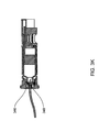
- FIG. 3A is a top-level view of an infusion pump according to one embodiment
- FIG. 3B is an exploded view of a drive mechanism for the infusion pump of FIG. 3A ;
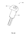
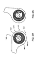
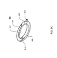
- FIG. 3C is an isometric views of one embodiment of a reservoir and locking hub assembly according to one embodiment
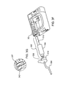
- FIG. 3D is an exploded isometric view of a locking hub and a reservoir according to one embodiment
- FIG. 3E is an isometric view of one embodiment of the reservoir assembly
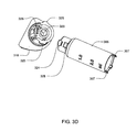
- FIG. 3F shows an embodiment of a pump barrel locking mechanism
- FIG. 3G shows a magnified view according to FIG. 3F ;
- FIGS. 3H-3I shows the relation of the drive screw to the plunger rod for the infusion pump of FIG. 3A ;
- FIG. 3J shows a connection from one embodiment of a reservoir to a tubing set
- FIG. 3K illustrates another method of connecting one embodiment of a reservoir to a tubing set
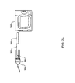
- FIG. 3L shows an adapter for using a small diameter reservoir with the pump assembly according to one embodiment
- FIGS. 3M-N are on-axis views of the adapter of FIG. 3L ;
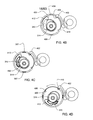
- FIG. 4A is an exploded view of one embodiment of the reservoir and locking hub assembly with portions of the loading and drive assembly of one embodiment of the infusion pump assembly;
- FIGS. 4B-4D are partial views of the loading of the reservoir assembly onto the drive assembly
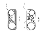
- FIGS. 4E-4F are top and bottom views of the hub and battery end cap according to one embodiment of the infusion pump apparatus
- FIG. 4G-4I are bottom, side and top views, respectively, of one embodiment of the locking disc
- FIGS. 4J-4L are isometric views of one embodiment of the locking disc
- FIGS. 4M-4N are partial illustrative views of the loading of the reservoir assembly onto the drive assembly of one embodiment of the infusion pump apparatus
- FIG. 5A is an isometric view of one embodiment of the plunger and plunger rod apparatus
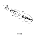
- FIG. 5B is an isometric view of one embodiments of the reservoir and locking hub assembly
- FIG. 5C is an isometric view of the plunger and plunger rod apparatus according to the reservoir and locking hub assembly shown in FIG. 5B ;
- FIGS. 5D-5E are isometric and cross sectional views, respectively, of the plunger seal apparatus according to one embodiment
- FIG. 5F is a cross sectional cut-off view of the assembled plunger apparatus of FIG. 5C ;
- FIG. 5G-5P are various embodiments of the plunger seal apparatus
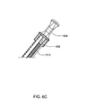
- FIGS. 6A-6B are views of one embodiment of the filling aid apparatus
- FIGS. 6C-6D are isometric views of the filling aid apparatus of FIGS. 6A-6B together with a plunger rod, both attached to the plunger rod and detached from the plunger rod, respectively;
- FIGS. 6E-6F are isometric views of one embodiment of the filling aid apparatus together with a plunger rod, both attached to the plunger rod and detached from the plunger rod, respectively;
- FIGS. 6G-6I are isometric views of alternate embodiments of the filling aid together with a plunger rod
- FIGS. 7A-7B are isometric views of various portions of one embodiment of the infusion pump assembly
- FIGS. 7C-7D are isometric views of the reservoir assembly together with the drive screw and the strain gauge according to one embodiment of the infusion pump apparatus;
- FIG. 7E is an magnified isometric view of a plunger rod together with an optical displacement sensor according to one embodiment of the infusion pump apparatus;
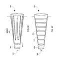
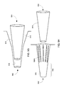
- FIGS. 8A-8D are various alternate embodiments of the reservoir assembly
- FIGS. 9A-9B are cross-sectional views of a medium connector assembly included within the infusion pump assembly of FIG. 1 ;
- FIGS. 9C-9D are cross-sectional views of a medium connector assembly included within the infusion pump assembly of FIG. 1 ;
- FIGS. 9E-9F are cross-sectional views of a medium connector assembly included within the infusion pump assembly of FIG. 1 ;
- FIGS. 9G-H are cross-sectional views of a medium connector assembly included within the infusion pump assembly of FIG. 1 ;
- FIGS. 9I-J are cross-sectional views of a medium connector assembly included within the infusion pump assembly of FIG. 1 ;
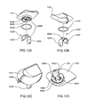
- FIG. 10A is an isometric view of a removable cover assembly for use with the infusion pump assembly of FIG. 1 ;
- FIG. 10B is an alternative isometric view of the removable cover assembly of FIG. 10A ;
- FIG. 10C is a cross-sectional view of the removable cover assembly of FIG. 10A ;
- FIG. 11 is an alternative isometric view of the removable cover assembly of FIG. 10A ;
- FIG. 12A-12D are isometric views of an alternative embodiment of the removable cover assembly of FIG. 4 ;
- FIG. 13 is a diagrammatic view of the infusion pump assembly of FIG. 1 ;
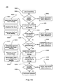
- FIG. 14 is a flowchart of a process executed by the infusion pump assembly of FIG. 1 ;
- FIG. 15 is a flowchart of a process executed by the infusion pump assembly of FIG. 1 ;
- FIG. 16 is a timeline illustrative of a plurality of discrete infusion events
- FIG. 17 is a more detailed view of two discrete infusion events included within FIG. 16 .
- FIG. 18 is a diagrammatic view of a storage array included within the infusion pump assembly of FIG. 1 ;
- FIG. 19 is a flowchart of a process executed by the infusion pump assembly of FIG. 1 ;
- FIG. 20 is an illustrative view of one embodiment of a remote control assembly.
- Infusion pump assembly 100 may be housed within enclosure assembly 102 .
- Infusion pump assembly 100 may include display system 104 that may be visible through enclosure assembly 102 .
- One or more switch assemblies/input devices 106 , 108 , 110 may be positioned about various portions of enclosure assembly 102 .
- Enclosure assembly 102 may include infusion port assembly 112 to which cannula assembly 114 may be releasably coupled.
- Removable cover assembly 116 may allow access to power supply cavity 118 (shown in phantom on FIG. 2 ).
- Infusion pump assembly 100 may be configured to deliver infusible fluid 200 to user 202 .
- Infusible fluid 200 may be delivered intravenously (i.e., into a vein), subcutaneously (i.e., into the skin), arterially (i.e., into an artery), and epidurally (i.e., into the epidural space).
- Examples of infusible fluid 200 may include but are not limited to insulin, nutrients, saline solution, antibiotics, analgesics, anesthetics, hormones, vasoactive drugs, and chelation drugs, and any other therapeutic fluids
- Infusion pump assembly 100 may include processing logic 204 that executes one or more processes that may be required for infusion pump assembly 100 to operate properly.
- Processing logic 204 may include one or more microprocessors (not shown), one or more input/output controllers (not shown), and cache memory devices (not shown).
- One or more data buses and/or memory buses may be used to interconnect processing logic 204 with one or more subsystems.
- Examples of the subsystems interconnected with processing logic 204 may include but are not limited to memory system 206 , input system 208 , display system 104 , vibration system 210 , audio system 212 , motor assembly 214 , force sensor 216 , and displacement detection device 218 .
- Infusion pump assembly 100 may include primary power supply 220 (e.g. a battery) configured to be removable installable within power supply cavity 118 and to provide electrical power to at least a portion of processing logic 204 and one or more of the subsystems (e.g., memory system 206 , input system 208 , display system 104 , vibration system 210 , audio system 212 , motor assembly 214 , force sensor 216 , and displacement detection device 218 ).
- primary power supply 220 e.g. a battery
- the subsystems e.g., memory system 206 , input system 208 , display system 104 , vibration system 210 , audio system 212 , motor assembly 214 , force sensor 216
- Infusion pump assembly 100 may include reservoir assembly 222 configured to contain infusible fluid 200 .
- reservoir assembly 222 may be a reservoir assembly similar to that described in U.S. Patent Application Publication No. US 2004-0135078-A1, published Jul. 15, 2004, which is herein incorporated by reference in its entirety.
- the reservoir assembly may be any assembly in which fluid may be acted upon such that at least a portion of the fluid may flow out of the reservoir assembly, for example, the reservoir assembly, in various embodiments, may include but is not limited to: a barrel with a plunger, a cassette or a container at least partially constructed of a flexible membrane.
- Plunger assembly 224 may be configured to displace infusible fluid 200 from reservoir assembly 222 through cannula assembly 114 (which may be coupled to infusion pump assembly 100 via infusion port assembly 112 ) so that infusible fluid 200 may be delivered to user 202 .
- plunger assembly 224 is shown to be displaceable by partial nut assembly 226 , which may engage lead screw assembly 228 that may be rotatable by motor assembly 214 in response to signals received from processing logic 204 .
- the combination of motor assembly 214 , plunger assembly 224 , partial nut assembly 226 , and lead screw assembly 228 may form a pump assembly that effectuates the dispensing of infusible fluid 200 contained within reservoir assembly 222 .
- partial nut assembly 226 may include but is not limited to a nut assembly that is configured to wrap around lead screw assembly 228 by e.g., 30 degrees.
- the pump assembly may be similar to one described in U.S. Pat. No. 7,306,578, issued Dec. 11, 2007, which is herein incorporated by reference in its entirety.
- infusible fluid 200 may be delivered to user 202 in accordance with e.g. a defined delivery schedule.
- infusion pump assembly 100 is configured to provide 0.00025 mL of infusible fluid 200 to user 202 every three minutes.
- processing logic 204 may provide the appropriate drive signals to motor assembly 214 to allow motor assembly 30 to rotate lead screw assembly 228 the appropriate amount so that partial nut assembly 226 (and therefore plunger assembly 224 ) may be displaced the appropriate amount in the direction of arrow 230 so that 0.00025 mL of infusible fluid 200 are provided to user 202 (via cannula 114 ).
- volume of infusible fluid 200 that may be provided to user 202 may vary based upon, at least in part, the nature of the infusible fluid (e.g., the type of fluid, concentration, etc.), use parameters (e.g., treatment type, dosage, etc.). As such the foregoing illustrative example should not be construed as a limitation of the present disclosure.
- Force sensor 216 may be configured to provide processing logic 204 with data concerning the force required to drive plunger assembly 224 into reservoir assembly 222 .
- Force sensor 216 may include one or more strain gauges and/or pressure sensing gauges and may be positioned between motor assembly 214 and an immovable object (e.g. bracket assembly 232 ) included within infusion pump assembly 100 .
- force sensor 216 includes four strain gauges (not shown), such that: two of the four strain gauges are configured to be compressed when driving plunger 222 into reservoir assembly 222 ; and two of the four strain gauges are configured to be stretched when driving plunger 222 into reservoir assembly 222 .
- the four strain gauges (not shown) may be connected to a Wheatstone Bridge (not shown) that produces an analog force signal (not shown) that is a function of the pressure sensed by force sensor 216 .
- the analog force signal (not shown) produced by force sensor 216 may be provided to an analog-to-digital converter (not shown) that may convert the analog force signal (not shown) into a digital force signal (not shown) that may be provided to processing logic 204 .
- An amplifier assembly (not shown) may be positioned prior to the above-described analog-to-digital converter and may be configured to amplify the output of e.g., force sensor 216 to a level sufficient to be processed by the above-described analog-to-digital converter.
- Motor assembly 214 may be configured as e.g., a brush-type DC electric motor. Further, motor assembly 214 may include a reduction gear assembly (not shown) that e.g. requires motor assembly 214 to rotate three-thousand revolutions for each revolution of lead screw assembly 228 , thus increasing the torque and resolution of motor assembly 214 by a factor of three-thousand.
- a reduction gear assembly (not shown) that e.g. requires motor assembly 214 to rotate three-thousand revolutions for each revolution of lead screw assembly 228 , thus increasing the torque and resolution of motor assembly 214 by a factor of three-thousand.
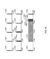
- FIG. 3A is an overall view of an infusion pump according to one embodiment.
- a pump assembly 300 contains the components needed to cause a reservoir assembly 302 to deliver medication or any liquid to a user.
- the reservoir assembly 302 may contain enough liquid, e.g., medication, such as, but not limited to, insulin, for several days for a typical user.
- a tubing set 304 connected to the reservoir assembly 302 , includes a cannula (not shown) through which the medication is delivered to the user.
- Reservoir assembly 302 may include reservoir 306 , plunger 308 and plunger rod 310 .
- Reservoir 306 may contain the medication for delivery to the user and is of variable interior volume. The interior volume may be the liquid capacity of reservoir 306 .
- Plunger 308 may be inserted into the bottom of the reservoir 306 , and may cause the volume of reservoir 306 to change as plunger 308 is displaced along the longitudinal axis of reservoir 306 .
- Plunger rod 310 may be connected to plunger 308 with the plunger rod's longitudinal axis displaced from and parallel to the longitudinal axis of reservoir 306 .
- Plunger rod 310 may be threaded for at least a portion of plunger rod's 310 length.
- cylindrical pump barrel 312 receives reservoir assembly 302 .
- Pump barrel 312 may constrain plunger rod 310 , orienting plunger rod 310 along the longitudinal axis of pump barrel 312 .
- Pump barrel 312 may be contained in pump assembly 300 and, in some embodiments, may contain locking tab 317 , which may prevent rotation of pump barrel 312 with respect to pump assembly 300 .
- Gear box 316 in pump assembly 300 may include drive screw 314 along with motor and gears to turn drive screw 314 .
- Drive screw 314 may be threaded and the screw's longitudinal axis may be aligned parallel to and may be displaced from the longitudinal axis of pump barrel 312 .
- Locking hub 318 may be attached to the top of reservoir 306 .
- reservoir 306 may be sized to accommodate any volume desired.
- reservoir 306 may accommodate a volume of 2.5 ml, however, in various other embodiments, reservoir 306 may be sized to accommodate a smaller or larger volume.
- reservoir 306 volume may change as the plunger is displaced along the longitudinal axis of reservoir 306 .
- locking hub 318 may be connected to tubing set (not shown, an embodiment of the tubing set is shown in FIG. 3A as 304 ) such that the liquid in the reservoir may flow through the locking hub to the tubing.
- reservoir 306 may also include reservoir alignment tabs 307 and reservoir bottom 305 .
- plunger rod 310 in the exemplary embodiment, may include a threaded portion 320 and a notched portion 322 .
- the threaded portion may thread to drive screw 314 .
- Notched portion 322 may be used, in the exemplary embodiment, to encode information relating to reservoir assembly 302 , including but not limited to the information, the methods and devices described in U.S. Patent Application Publication US 2004/0135078 A1, published on Jul. 15, 2004 and entitled Optical Displacement Sensor for Infusion Devices, which is herein incorporated by reference in its entirety.
- locking hub 310 may include a female part 329 as well as tab 326
- reservoir 306 may include a male part 324 as well as slot 328 .
- Male part 324 and female part 329 may mate to form a luer connection.
- Tab 326 and slot 328 may lock together when mated and turned, one part relative to its mating part, such that tab 326 may slide into the slot 328 .
- FIG. 3E another embodiment of reservoir assembly 330 is shown.
- hub portion 332 and reservoir portion 334 are connected, and in one embodiment, are molded as a single part.
- the pump barrel 312 includes a clearance hole (not shown, shown in FIG. 3H as 340 ) that guides the plunger rod 310 during insertion of the reservoir assembly 302 into the pump barrel 312 .
- the pump barrel 312 maintains a fixed position relative to the pump assembly 300 .
- the position of the pump barrel 312 relative to the pump assembly 300 may be maintained, for example, by a locking tab 317 included in the pump barrel 312 that engages a pump barrel stop 342 in the pump assembly 300 .
- the locking hub 318 may include a flange 338 which dislodges the locking tab 340 from the pump barrel stop 342 when the locking hub 318 turns, allowing the locking hub 318 to rotate the pump barrel 312 .
- FIGS. 3G-3H show views along the longitudinal axis of the pump barrel 312 showing the relation of the drive screw 314 to the plunger rod in a loading position and in an engaged position, respectively.
- the reservoir assembly 302 is positioned for loading so that the plunger rod 310 does not contact the drive screw 314 , as shown in FIG. 3G .
- the plunger rod 310 clearance from the drive screw 314 is determined by the placement of the clearance hole 340 in the pump barrel 312 base, which hole 340 receives and guides the plunger rod 310 .
- the clearance hole 340 may be tapered to ease insertion of the plunger rod 310 .
- the drive screw 314 fits in a clearance hole 340 in the pump barrel 312 .
- the plunger rod threads and the drive screw threads are buttress threads. These embodiments may be advantageous in that they eliminate reaction forces on the plunger rod normal to the direction of the rod's longitudinal axis. Such reaction forces may cause the rod to deflect and skip a thread on the drive screw, resulting in under delivery of medication to the user. Buttress threads eliminate the normal component of the reaction force.
- the locking hub 318 may be connected to the reservoir 306 by a tapered luer connection.
- the reservoir 306 has a male luer taper integrally molded into the reservoir's top 344 .
- Surrounding the male luer is an annulus with an internal female thread.
- the locking hub 318 contains the mating female luer and threaded male connection.
- a needle connection is provided between reservoir 306 and locking hub 318 .
- the reservoir includes a rubber septum 346 that is attached to the reservoir with a crimped metal collar.
- a needle 348 integral to the hub, pierces the septum and fluid can then flow from the reservoir to the tubing set.
- an adapter 350 is provided to permit a reservoir 352 whose diameter is substantially smaller than the diameter of a pump barrel to be used with the pump assembly 300 .
- the adapter 350 may be a separate component or may be integrated into the locking hub 354 .
- the locking hub 354 in some embodiments, may be one of the embodiments described herein, and sized accordingly.
- the adapter 350 aligns and offsets the reservoir's 352 axis parallel to the longitudinal axis of the pump barrel so that the plunger rod 356 , when rotated, mates with the drive screw (not shown).
- FIGS. 3L-3M show an on-axis view of the small diameter reservoir 352 when placed in the adapter 350 .
- the offset provided by the adapter allows the plunger rod 356 , when mated with the plunger 308 and reservoir 352 , to engage the drive screw 314 in a similar fashion as for the first embodiment, described above.
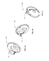
- a cylindrical pump barrel 312 shown here inside a pump barrel housing 360 , receives the reservoir assembly 302 .
- the pump barrel 312 terminates with a locking disc 400 .
- the pump barrel 312 constrains the plunger rod 310 , orienting the plunger rod 310 along the longitudinal axis of the pump barrel 312 .
- the pump barrel 312 is contained in the pump barrel housing 360 , which is contained in the pump assembly 300 .
- the locking disc 400 in the exemplary embodiment, contacts a locking tab (shown in FIG. 4B as 402 ), which is in the pump gear box 364 .
- the locking tab 402 prevents rotation of the locking disc 400 with respect to the pump assembly 300 .
- the locking disc 400 may not include a locking tab 402 .
- a gear box 364 in the pump assembly 300 includes a drive screw 314 along with motor and gears to turn the drive screw 314 , and, as discussed above, in some embodiments, a locking tab 402 for locking the locking disc 400 .
- the drive screw 314 is threaded and the screw's longitudinal axis is aligned parallel to and displaced from the longitudinal axis of the pump barrel 312 .
- a locking hub 318 is attached to the top of the reservoir 306 .
- the plunger rod 310 is connected to the plunger 308 .
- the plunger rod 310 and plunger 308 are a single molded part.
- O-rings 366 fit over the plunger 308 .
- the O-rings may be molded into the plunger 308 .
- the locking hub 318 additionally includes locking hub alignment tabs 325 .
- the pump assembly 300 includes a hub and battery end cap 404 .
- the hub section of the hub and battery end cap 404 includes complementary opening for the locking hub 318 , including the locking hub alignment tabs 325 .
- the reservoir assembly 302 is mated with the locking hub 318 , to load the reservoir into the pump barrel 312 , the reservoir must be oriented correctly with respect to the locking hub alignment tabs 325 and the complementary opening in the hub and battery end cap 404 .
- the reservoir alignment tabs 307 will thus also be aligned with the locking hub alignment tabs 325 .
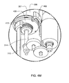
- the locking disc 400 includes a clearance hole 340 , which, in the exemplary embodiment is tapered for easy insertion, but in some embodiments, is not tapered. Additionally, the reservoir tab openings 406 , plunger rod support 412 and first and second locking tab notches 408 , 410 are shown. As discussed above, the reservoir alignment tabs 307 are aligned with the locking hub alignment tabs 325 . The orientation assured by the hub and battery end cap 404 assures that the plunger rod 310 will be in the correct orientation to fit through the clearance hole 340 , the reservoir alignment tabs 307 will mate with the reservoir tab opening 406 , and the reservoir bottom 305 displaces the locking tab 402 .
- the locking disc 400 may include only a first locking tab notch 408 , or, in some embodiments, may not include any locking tab notches.
- the locking tab notches 408 , 410 maintain the orientation of the locking disc 400 for ease of loading the reservoir and locking hub assembly.
- the second locking tab notch 408 contributes to maintaining the plunger rod 310 and drive screw 314 relationship.
- the reservoir tab openings 406 are included in the exemplary embodiment of the locking disc 400 , some embodiments of the locking disc 400 do not include reservoir tab openings 406 . In these embodiments, the reservoir does not include reservoir alignment tabs 307 (shown in FIGS. 3C-3D ).
- the reservoir tab openings 406 aid in the rotation of the locking disc 400 .
- the user having aligned the reservoir and locking hub assembly with the hub and battery cap 404 , drops the reservoir and locking hub assembly into the pump barrel 312 and applies a slight pressure to the locking hub 318 .
- the user then applies torque to the locking hub 318 to complete the loading process.
- the torque applied to the locking hub is transmitted from the reservoir alignment tabs 307 to the locking disc 400 rather than from the locking hub 318 to the plunger rod 310 .
- the reservoir alignment tabs 307 together with the reservoir tab openings 406 work together to take up the torque applied to the reservoir and locking hub assembly which contributes to maintaining the integrity of the plunger rod 310 while also ensuring proper engagement of the plunger rod 310 onto the drive screw 314 .
- bottom view of the locking disc 400 is shown with the locking tab 402 engaged with one of the locking tab notches 408 .
- the clearance hole 340 is shown empty of the plunger rod.
- the drive screw 314 is shown and the plunger rod support 412 is also shown.
- the plunger rod 310 is shown having fit through the clearance hole 340 .
- the reservoir alignment tabs 307 are shown having mated with the reservoir tab openings 406 , and the locking tab 402 is deflected from the locking tab notch 408 .
- the plunger rod support 412 is shown along part of the plunger rod 310 .
- the plunger rod support 412 contributes to maintaining the integrity of the relationship of the plunger rod 310 and the drive screw 314 such that the drive screw 314 of the plunger rod 310 maintain connection and the plunger rod 310 is not deflected.
- the locking disc 400 is shown after rotation and reservoir loading is complete, i.e., in the loaded position.
- the plunger rod 310 is engaged to the drive screw 314 .
- the second locking tab notch 410 is now engaged with the locking tab 402 .
- the locking disc 400 is locked from continuing further rotation.
- FIGS. 4M-4N a sequential illustration of the loading of the reservoir and engagement of the drive screw 314 to the plunger rod 310 is shown.
- the reservoir 306 disengages the locking tab 402 from the first locking tab notch 408 .
- the reservoir alignment tab 307 (the other tab is obscured) mates with the reservoir tab opening 406 .
- the plunger rod 310 is engaged with the drive screw 314 .
- the locking tab 402 is being engaged with the second locking tab notch 410 .
- loading the reservoir into the pump barrel and engaging the plunger rod to the drive screw includes two steps. First, aligning the locking hub alignment tabs with the hub and battery end cap and dropping the reservoir and locking hub assembly into the pump barrel (the plunger rod being inherently aligned with the clearance hole of the locking disc). Second, rotating the locking hub until rotation stops, i.e., the locking tab has engaged with the second locking tab notch.
- the hub and battery end cap 404 may include an loading alignment feature 420
- the reservoir may also include a marking or other alignment feature, aligning the marking on the reservoir with the loading alignment feature 420 assures the reservoir assembly is aligned for dropping the reservoir and locking hub assembly into the pump barrel and completion of the loading steps.
- the loading alignment feature 420 is a notch molded into the plastic of the hub and battery end cap 404 .
- the loading alignment feature 420 may be a bump, raised dimple, notch of a different shape, or a painted marking, i.e., any feature that may be utilized by the user in loading the reservoir and locking hub assembly.
- the complementary feature on the reservoir may be any marking, for example, a painted marking with an indication of the direction of loading, e.g., “pump ⁇ ”, “ ⁇ ”, or, in some embodiments, a simple vertical line of any length, a dot or other symbol that may be utilized by the user in loading the reservoir and locking hub assembly.
- these alignment features further simplify the method of loading the reservoir and locking hub assembly into the pump assembly.
- the hub and battery end cap is shown populated with a locking hub 108 and a battery cap 110 .
- the locking hub 108 sits flush with the pump assembly.
- reservoir loading is advantageously simplified in that the alignment features assure that the reservoir, when dropped into the pump barrel, the plunger rod and reservoir alignment tabs are aligned with the locking disc and, the rotation of the locking hub until the locking hub is flush with the pump assembly assures that reservoir loaded and the plunger rod is threaded to the drive screw.
- the plunger 308 includes two O-rings 366 .
- the O-rings 366 and plunger 308 may be one piece and may be made from a material that provides ample sealing properties.
- the plunger seal 506 is designed to function as a double o-ring plunger, however, is molded as a single part.
- the plunger seal 506 fits over the plunger 504 , which, in some embodiments, is made from plastic, and in some embodiments, is made from the same plastic as the plunger rod 310 .
- the plunger cap 508 fits over the plunger seal 506 .
- the reservoir 306 and reservoir bottom 305 may be as described in the above described embodiments. Referring also to FIGS. 5D-5E , the plunger seal 506 is shown.
- the top ring-like feature of the seal is thicker than the bottom ring-like feature.
- the bottom ring-like feature may be the thicker ring-like feature, and in some embodiments, both ring-like features may be the same thickness.
- FIG. 5F a cross section of the assembled plunger of the embodiments shown in FIGS. 5B-5E is shown.
- the plunger seal 506 fits around the plunger 504 and the plunger cap 504 snaps over the plunger seal 506 .
- FIGS. 5G-5P various embodiments of the plunger seal 506 described above are shown.
- the plunger rod is connected to the plunger, and is part of the reservoir assembly.
- the reservoir functions to hold a volume of liquid for delivery by the infusion pump assembly. Filling the reservoir with a liquid, e.g. insulin, prior to leading the reservoir assembly into the pump assembly is preferred.
- a user loads the reservoir with insulin (or another liquid as discussed herein), attached the locking hub (in the exemplary embodiments, although, as discussed above, in some embodiments, the locking hub may be integrated with the reservoir) and loads the reservoir assembly with locking hub into the pump assembly.
- the plunger rod is designed, as shown herein, to engage with the drive screw and be driven by the drive screw.
- a filling aid may be desirable.
- the filling aid 600 is designed to engage with the threaded portion of the plunger rod 310 as described above, i.e., the filling aid includes a mating thread portion 602 .
- the filling aid 600 slides onto the plunger rod 310 , and as the mating thread portion 602 engages with the plunger rod threads 320 , the filling aid 600 is securely fastened to the plunger rod 310 .
- the handle 604 in the exemplary embodiment, is shaped to accommodate user's fingers and serves as pull. In practice, the user loads the reservoir by pulling back on the handle 604 .
- the filling aid 600 may be easily removed from the plunger rod by moving the filling aid 600 such that the threads disengage with the plunger rod threads.
- the filling aid 600 in the exemplary embodiment, is designed to have tolerances such that the plunger rod threads are not damaged during the filling process.
- the filling aid may be different shapes, for example, larger, or the handle may be shaped differently, to accommodate those users with arthritis or other ailments that may prevent them from easily utilizing the filling aid as shown.
- An alternate embodiment is shown in FIGS. 6E-6F .
- the filling aid 600 is made from plastic, however, in other embodiments, the filling aid 600 may be made from any materials, including but not limited to, stainless steel or aluminum.
- the filling aid 606 may be connected to the plunger rod 301 by way of a plastic piece 608 .
- the plastic piece 608 is manufactured such that the filling aid 606 may be removed from the plunger rod 310 by bending the plastic piece, i.e., the filling aid 606 snaps off the plunger rod 310 .
- the filling aid 606 in these FIGS. is shown having a particular shape, in other embodiments, the shape may be any of the other filling aid embodiments shown herein, or others that may be designed as discussed above.
- the filling aid 606 and plastic piece 608 may be molded with the plunger rod 310 .
- the pump assembly 100 includes a housing, which, in the exemplary embodiment, is made from an aluminum portion, plastic portions, and rubber portions. However, in various embodiments, the materials and the portions vary, and include but are not limited to, rubber, aluminum, plastic, stainless steel, and any other suitable materials.
- the back of the housing, shown in FIG. 1B includes a contour.
- FIGS. 7A-7B portions of the housing has been removed.
- the switch assemblies/input devices and the user interface screen have been removed.
- the pump barrel 312 is shown with a reservoir 306 inside.
- the battery compartment 706 is shown in FIG. 7A
- the pump assembly 100 is shown without the battery compartment 706 is FIG. 7B .
- Various features of the battery compartment 706 are described herein.
- the gear box 364 is shown assembled with the pump housing 360 in the pump assembly 100 .
- the hub and battery end cap 404 is shown assembled on the pump assembly 100
- a reservoir assembly 312 is shown engaged to the drive screw 314 and in contact with the strain gauge 708 .
- the strain gauge 708 is in contact with the drive screw 314 .
- the pressure measurements of the strain gauge 708 are taken by an electrical contact 710 .
- the strain gauge 708 measures the pressure exerted by the drive screw 314 .
- the optical sensor as described above and in more detail in U.S. Patent Application Publication US 2004/0135078 A1, published on Jul. 15, 2004 and entitled Optical Displacement Sensor for Infusion Devices, as used in some embodiments of the infusion pump apparatus, is a sensor used to determine whether the plunger rod 310 has moved and/or advanced and additionally, may also determine whether the plunger rod 310 has moved and/or advanced the intended distance.
- the pump apparatus using the occlusion detection methods and devices, can determine if the drive screw is unable to advance, and also, can determine if the plunger rod has moved and the distance in which it has moved.
- FIGS. 8A-8D alternate embodiments of the reservoir assembly are shown.
- the pumping assembly shape and size may vary from the ones shown herein.
- the pump assembly may be round or smaller in shape. Therefore, it may be beneficial for the reservoir assembly to accommodate the smaller or rounded shape without having to sacrifice total volume.
- Exemplary embodiments of these alternate embodiment reservoir assemblies are shown in FIGS. 8A-8C . However, it should be understood these are by example only.
- the alternate embodiment reservoir assembly may be larger, smaller, or include a larger or smaller angle.
- a curved reservoir assembly 800 is shown.
- the angle indicated may have a value of greater than or less than 180 degrees.
- the reservoir assembly 800 may have an angle of 150 degrees.
- the reservoir assembly 800 may form a helical shape.
- the reservoir assembly 800 may be any shape desired, including having one or more portions rounded or curved, and/or one or more portions straight or approaching straight.
- FIGS. 8B-8D another embodiment of the alternate embodiment reservoir assembly is shown.
- the reservoir 802 and plunger 804 assembly is shown as having a round or approaching round shape.
- the reservoir 802 in some embodiments, and as shown in FIGS. 8B-8D , may be a channel in a housing 806 .
- the reservoir 802 may be cylindrical, and the ends 808 , 810 of the plunger 804 may be circular, however, the plunger 804 may be flat 804 as shown.
- the plunger 804 may be advanced by applying pressure to the end 808 of the plunger 804 by a mechanical feature (not shown), which, in some embodiments, may be located in the center 812 of the housing 806 , or in other embodiments, elsewhere in the pump assembly within engageable proximity to the plunger 804 .
- the reservoir 802 may be filled with liquid using inlet 814 .
- enclosure assembly 102 may include infusion port assembly 112 to which cannula assembly 114 may be releasably coupled.
- a portion of infusion port assembly 112 and a portion of cannula assembly 114 may form a medium connector assembly for releasably coupling infusion port assembly 112 to cannula assembly 114 and effectuating the delivery of infusible fluid 200 to user 202 .
- FIG. 9A there is shown one exemplary embodiment of a medium connector assembly 900 for connecting medium carrying components (not shown) and allowing the flow of medium therebetween.
- medium carrying components may include, but are not limited to, a delivery catheter and an insulin delivery pump, a fluid supply (such as an intravenous fluid supply bag, a dialysate supply, etc.) and a pump supply catheter, or the like.
- Connector assembly 900 may include medium connector 902 associated with a first medium carrying component (not shown) and mating connector 904 associated with a second medium carrying component.
- Medium connector 902 may include passage 906 to allow for the flow of medium.
- the medium flowing between the medium carrying components, e.g., via passage 906 may include liquids (e.g., insulin, dialysate, saline solution, or the like), gases (e.g., air, oxygen, nitrogen, or the like), suspensions, or the like.
- medium connector 902 may include multi-portion engagement surface 908 , generally, positioned about passage 906 . Multi-portion engagement surface 908 may include first surface portion 910 , and second surface portion 912 .
- first surface portion 910 of multi-portion engagement surface 908 may be configured to provide an interference fit with corresponding sealing surface 914 of mating connector 904 .
- second surface portion 912 of multi-portion engagement surface 908 may be configured to provide a clearance fit with corresponding sealing surface 914 of mating connector 904 .
- the ratio of first surface portion 910 and second surface portion 912 may be selected to regulate an engagement for between medium connector 902 and mating connector 904 .
- corresponding sealing surface 914 of mating connector 904 may include a tapered surface, e.g., which may include a 6% taper (e.g., approximately 3.4 degree included taper) of a standard Luer taper connector (e.g., as defined by the ISO 594 standard).
- corresponding sealing surface 914 may include tapers other than a 6% Luer taper.
- Multi-portion engagement surface 908 may similarly include a tapered surface, in which first surface portion 910 may have a first taper angle, and second surface portion 912 may have a second taper angle that is less than the first taper angle.
- the second taper angle may approach zero, such that second surface portion 912 may be generally cylindrical (e.g., may include a slight taper, such as a draft angle to facilitate manufacture).
- second surface portion 912 may include other, non-cylindrical, taper angles.
- first surface portion 910 of multi-portion engagement surface 908 may include a first taper angle corresponding to the angle of corresponding sealing surface 914 of mating connector 904 (e.g., a 6% taper).
- first taper angle corresponding to the angle of corresponding sealing surface 914 of mating connector 904 e.g., a 6% taper.
- the corresponding taper of first surface portion 910 may provide an interference fit with corresponding sealing surface 914 of mating connector 904 .
- the second taper angle of second surface portion 912 may provide a clearance fit with corresponding sealing surface 914 of mating connector 904 , e.g., which may result in at least partial clearance 916 between second surface portion 912 and corresponding sealing surface 914 .
- the contact surface area of medium connector 902 and mating connector 904 may remain generally constant once first surface portion 910 has engaged corresponding sealing surface 914 .
- first surface portion 910 may be configured to provide an interference fit with corresponding sealing surface 914
- second surface portion 912 of multi-portion engagement surface 908 may be configured to provide a clearance fit with corresponding sealing surface 914
- only first surface portion 910 may engage corresponding sealing surface 914 .
- first surface portion 910 engages corresponding sealing surface 914
- further insertion of medium connector 902 relative to mating connector 904 may be attributable to the elastic and/or plastic deformation force of medium connector 902 in the region of first surface portion 910 and/or of mating connector 904 in the region of contact between corresponding sealing surface 914 and first surface portion 910 (e.g., as first surface portion 910 is forced into the progressively smaller opening provided by corresponding sealing surface 914 ), and the frictional interaction between first surface portion 910 and corresponding sealing surface 914 of mating connector 904 .
- the ratio of first surface portion 910 and second surface portion 912 may be selected to regulate an engagement force between medium connector 902 and mating connector 904 .
- second surface portion 912 may be configured to provide a clearance fit with corresponding sealing surface 914 , and as such may not contribute to the engagement force (e.g., the insertion force per increment of axial insertion) between medium connector 902 and mating connector 904 . Therefore, the ratio of first surface portion 910 to second surface portion 912 may be increased to increase the engagement force between medium connector 902 and mating connector 904 . Conversely, the ratio of first surface portion 910 to second surface portion 912 may be decreased to decrease the engagement force between medium connector 902 and mating connector 904 .
- the ability to regulate the engagement force between medium connector 902 and mating connector 904 may allow the use of features associated with medium connector 902 (and/or the first associated medium carrying component) and/or mating connector 904 (and/or the second associated medium carrying component) which may require a minimum insertion depth to be achieved within a selected range of insertion forces.
- medium connector 902 may include one or more retention features, e.g., which may facilitate a positive engagement and/or relative position between medium connector 902 and mating connector 904 . As shown in FIGS.
- the one or more retention features may include one or more snap-fit features (e.g., cooperating snap-fit features 918 , 920 A, respectively associated with medium connector 902 and mating connector 904 ).
- one or more of cooperating snap-fit features 918 , 920 A may be disposed on a cantilever feature (e.g., cantilever arm 922 ), e.g., which may facilitate engagement/dis-engagement of cooperating snap-fit features 918 , 920 A.
- Snap-fit features 918 , 920 A may require a minimum insertion depth to provide engagement therebetween.
- first surface portion 910 and second surface portion 912 may be selected to regulate the engagement force between medium connector 902 and mating connector 904 associated with the insertion depth necessary to provide engagement between snap-fit features 918 , 920 A. While regulating the engagement force between the medium connector and the mating connector has been described in connection with the use of retention features, this is not intended as a limitation of the present disclosure, as the ability to regulate the engagement force between the medium connector and the mating connector may equally be used for other purposes.
- the medium connector assembly may include medium connector 902 associated with a first medium carrying component (not shown) and mating connector 904 associated with a second medium carrying component.
- one or more of the cooperating snap-fit features e.g., cooperating snap-fit features 918 , 920 B
- the cooperating snap-fit features may be provided as a feature associated with one of the mating surfaces of the medium connector assembly (e.g., snap-fit feature 920 B may be formed on member 924 defining corresponding sealing surface 914 ).
- FIGS. 9A-9B and 9 C- 9 D various additional/alternative arrangements may be readily understood, and are contemplated by the present disclosure.
- the second surface portion may include one or more recesses.
- the second surface portion may include one or more recesses including one or more longitudinal slots (e.g., longitudinal slot 950 ), e.g., which may be formed in first surface portion 910 .
- Longitudinal slot 950 may be configured to provide a clearance fit with cooperating sealing surface 114 of mating connector 904 .
- longitudinal slot 950 may provide a second surface portion which may not engage cooperating sealing surface 914 when first surface portion 910 is fully engaged with cooperating sealing surface 914 of mating connector 904 .
- the ratio of first surface portion 910 and the radial slots may be selected to regulate the engagement force between medium connector 902 and mating connector 904 , e.g., in as much as longitudinal slot 950 may not provide a frictional engagement force with cooperating sealing surface 914 of mating connector 904 .
- the second surface portion may include one or more recesses that may include one or more radial slots (e.g., radial slot 952 ). Similar to the above-described longitudinal slots (e.g., longitudinal slot 950 ), radial slot 952 may be configured to provide a clearance fit with corresponding sealing surface 914 of mating connector 904 . As such, the ratio of first surface portion 910 and the radial slots (e.g., radial slot 952 ) may be selected to regulate the engagement force between medium connector 902 and mating connector 904 . For example, radial slot 952 may not provide a frictional engagement force with cooperating sealing surface 914 of mating connector 904 .
- radial slot 952 may not provide a frictional engagement force with cooperating sealing surface 914 of mating connector 904 .
- the one or more recesses may include various additional and/or alternative configurations (e.g., dimples, etc.), which may be configured to provide a clearance fit with the cooperating sealing surface of the mating connector.
- the ratio of the first surface portion and the second surface portion may be selected to regulate an engagement force between the medium connector and the mating connector.
- the number, arrangement, and character of the one or more recesses may vary according to design criteria and preference.
- medium connector 902 may additionally/alternatively be configured as a female connector portion.
- medium connector 902 may include a female connector portion having a multi-portion engagement surface including first surface portion 910 and second surface portion 912 .
- the multi-portion engagement surface may include a tapered surface, in which first surface portion 910 may have a first taper angle configured to provide an interference fit with cooperating sealing surface 914 of male mating connector 904 .
- second surface portion 912 may have a second taper angle that is greater than the first taper angle.
- second surface portion 912 may be configured to provide a clearance fit with cooperating sealing surface 914 of male mating connector 904 .
- the second surface portion may include one or more recesses.
- the one or more recesses may include one or more longitudinal slots (e.g., longitudinal slot 950 A, 950 B).
- first surface portion 910 may be configured to provide an interference fit with cooperating sealing surface 914 of male mating connector 904 .
- the second surface portion, including longitudinal slot 950 A, 950 B may be configured to provide a clearance fit with cooperating sealing surface 914 of male mating connector 904 .
- Medium connector 902 may include sealing region 954 , which may not include longitudinal slots, e.g., to thereby facilitate achieving a seal between first surface portion 910 and cooperating sealing surface 914 of mating connector 904 .
- the second surface portion may include one or more recesses, in which the one or more recesses may include one or more radial slots (e.g., radial slot 952 ).
- Radial slot 952 may be configured to provide a clearance fit with cooperating sealing surface 914 of male mating connector 904 .
- the one or more recesses may include various additional and/or alternative configurations (e.g., dimples, etc.), which may be configured to provide a clearance fit with the cooperating sealing surface of the mating connector.
- the ratio of the first surface portion and the second surface portion may be selected to regulate an engagement force between the medium connector and the mating connector.
- the number, arrangement, and character of the one or more recesses may vary according to design criteria and preference.
- infusion pump assembly 100 may include a removable cover assembly 116 configured to allow access to power supply cavity 118 (shown in phantom on FIG. 2 ).
- power supply cavity 118 (which may be formed by a combination of removable cover assembly 116 and a portion of enclosure assembly 102 ) may be configured to releasably receive primary power supply 220 . Additionally, power supply cavity 118 may be configured to prevent primary power supply 220 from being reverse-polarity electrically coupled to processing logic 204 For example, power supply cavity 118 may be configured to prevent positive terminal 1000 of primary power supply 220 from being electrically coupled to negative terminal 1002 of power supply cavity 118 and/or negative terminal 1004 of primary power supply 220 from being electrically coupled to positive terminal 1006 of power supply cavity 118 ).
- Configuring power supply cavity 118 to prevent primary power supply 220 from being reverse-polarity electrically coupled to processing logic 204 may provide various benefits.
- the configuration may prevent the loss of power from primary power supply 220 (e.g., discharge of the battery) where the primary power supply assembly 220 has been inserted incorrectly.
- this configuration may also be a safety feature to infusion pump assembly 100 .
- Infusion pump assembly 100 may rely on power for functionality.
- a user may rely on infusion pump assembly 100 to provide life-sustaining therapy, for example, by delivering insulin.
- preventing primary power supply 220 from being reverse-polarity electrically coupled to processing logic 204 may allow infusion pump assembly 100 to function for a longer time than if the incorrectly installed primary power supply 220 had been able to be reverse-polarity electrically coupled to processing logic 204 .
- Removable cover assembly 116 may be configured to allow access to power supply cavity 118 and effectuate the installation/replacement/removal of primary power supply 220 .
- primary power supply 220 may include but is not limited to a battery.
- the battery may include, but is not limited to, an A, AA, AAA, or AAAA battery, and the battery may be a lithium battery or alkaline battery.
- the battery may, in some embodiments, be a rechargeable battery.
- Removable cover assembly 116 may be configured to rotatably engage enclosure assembly 102 in the direction of arrow 1008 .
- removable cover assembly 116 may include first twist lock assembly 1010 (e.g., a protruding tab).
- Enclosure assembly 102 may include a second twist lock assembly 1012 (e.g., a slot) configured to releasably engage first twist lock assembly and effectuate the releasable engagement of the removable cover assembly and the enclosure assembly.
- removable cover assembly 116 and enclosure assembly 102 is described above as including first twist lock assembly 1010 and second twist lock assembly 1012 , this is for illustrative purposes only and is not intended to be a limitation of this disclosure, as other configurations are possible and are considered to be within the scope of this disclosure.
- one or more thread assemblies may be utilized to effectuate the above-described rotatable engagement.
- removable cover assembly 116 is described above as being configured to rotatably engage enclosure assembly 102 , this is for illustrative purposes only and is not intended to be a limitation of this disclosure, as other configurations are possible.
- removable cover assembly 116 may be configured to slidably engage enclosure assembly 102 (in the direction of arrow 1014 ) using a slide assembly (not shown).
- removable cover assembly 116 may be configured to be pressed into enclosure assembly 102 in the direction of arrow 1016 .
- Removable cover assembly 116 may include sealing assembly 1018 (e.g., an o-ring assembly) that is configured to releasably engage at least a portion of enclosure assembly 102 to form an essentially water-tight seal between removable cover assembly 116 and enclosure assembly 102 .
- sealing assembly 1018 e.g., an o-ring assembly
- sealing assembly 1018 includes an o-ring assembly included within removable cover assembly 116
- the o-ring assembly may be sized to effectuate a watertight (or essentially watertight) seal with a corresponding surface of enclosure assembly 102 .
- sealing assembly 1018 includes an o-ring assembly included within enclosure assembly 102
- the o-ring assembly may be sized to effectuate a watertight (or essentially watertight) seal with a corresponding surface of removable cover assembly 116 .
- Removable cover assembly 116 may include conductor assembly 1020 for electrically coupling positive terminal 1006 of removable cover assembly 116 with interior wall 120 ( FIG. 1D ) of power supply cavity 118 .
- conductor assembly 1020 may include a plurality of tabs (e.g., tabs 1022 , 1024 ) that may be electrically coupled to positive terminal 1006 of removable cover assembly 116 .
- Tabs 1022 , 1024 may be configured so that when removable cover assembly 116 releasably engages enclosure assembly 102 , tabs 1022 , 1024 may make electrical contact with interior wall 120 of power supply cavity 118 .
- Interior wall 120 of power supply cavity 118 may then be electrically coupled to the various components within infusion pump assembly 100 that require electrical power, examples of which may include but are not limited to processing logic 204 ,
- removable cover assembly 116 may be configured to prevent primary power supply 220 from being reverse-polarity electrically coupled to e.g., processing logic 204 .
- processing logic 204 e.g., processing logic 204 .
- removable cover assembly 116 may include insulator assembly 1026 that includes recess 1028 that is sized to receive positive terminal 1000 of primary power supply 220 and enable electrical contact with positive terminal 1006 of removable cover assembly 116 .
- Insulator assembly 1026 may be constructed of an insulating material, such as PVC plastic or bakelite.
- recess 1028 may be sized so that negative terminal 1004 of primary power supply 220 cannot make electrical contact with positive terminal 1006 (and may only make contact with insulator 1026 ), thus preventing primary power supply 220 from being electrically coupled to processing logic 204 in a reverse-polarity configuration.
- Removable cover assembly 116 ′ may include sealing assembly 1018 ′ (e.g., an o-ring assembly) that is configured to releasably engage at least a portion of enclosure assembly 102 to form an essentially water-tight seal between removable cover assembly 116 ′ and enclosure assembly 102 .
- sealing assembly 1018 ′ e.g., an o-ring assembly
- Removable cover assembly 116 ′ may include conductor assembly 1020 ′ for electrically coupling positive terminal 1006 ′ of removable cover assembly 116 ′ with interior wall 120 ( FIG. 1D ) of power supply cavity 118 ( FIG. 1D ).
- conductor assembly 1020 ′ may include a plurality of tabs (e.g., tabs 1022 ′, 1024 ′) that may be electrically coupled to positive terminal 1006 ′ of removable cover assembly 116 ′.
- Tabs 1022 ′, 1024 ′ may be configured so that when removable cover assembly 116 ′ releasably engages enclosure assembly 102 , tabs 1022 ′, 1024 ′ may make electrical contact with interior wall 120 of power supply cavity 118 .
- Interior wall 120 of power supply cavity 118 may then be electrically coupled to the various components within infusion pump assembly 100 that require electrical power, examples of which may include but are not limited to processing logic 204 ,
- removable cover assembly 116 ′ may include insulator assembly 1026 ′ that defines recess 1028 ′ that is sized to receive positive terminal 1000 ( FIG. 11 ) of primary power supply 220 ( FIG. 11 ) and enable electrical contact with positive terminal 1006 ′ of removable cover assembly 116 ′.
- Insulator assembly 1026 ′ which may be constructed of an insulating material (e.g., PVC plastic or bakelite), may be molded into and/or a portion of removable cover assembly 116 ′.
- recess 1028 ′ may be sized so that negative terminal 1004 ( FIG. 11 ) of primary power supply 220 cannot make electrical contact with positive terminal 1006 ′ (and may only make electrical contact with insulator 1026 ′, thus preventing primary power supply 220 from being electrically coupled to processing logic 204 in a reverse-polarity configuration.
- power supply cavity 118 is described above as having positive terminal 1006 positioned proximate removable cover assembly 116 , this is for illustrative purposes only and is not intended to be a limitation of this disclosure, as other configurations are possible and are considered to be within the scope of this disclosure.
- negative terminal 1002 may be positioned proximate removable cover assembly 116 .
- Processing logic 204 may include one or more circuit partitioning components 1300 , 1302 configured to divide processing logic 204 into primary processing logic 1304 and backup processing logic 1306 .
- Examples of one or more circuit partitioning components 1300 , 1302 may include but are not limited to diode assembly 1300 and current limiting assembly 1302 .
- Diode assembly 1300 may be configured to allow primary power supply 220 to charge backup power supply 1308 included within backup processing logic 1306 , while prohibiting backup power supply 1308 from providing backup electrical energy 1310 to primary processing logic 1304 in the event that some form of failure prevents primary electrical energy 1312 from providing primary processing logic 1304 .
- An example of backup power supply 1308 may include but is not limited to a super capacitor assembly.
- An example of such a super capacitor assembly may include but is not limited to an electric double-layer capacitor manufactured by Elna Co. Ltd. of Yokohama, Japan.
- Current limiting assembly 1302 may be configured to limit the amount of primary electrical energy 1312 available to charge backup power supply 1308 .
- the amount of current available from primary power supply 220 may be limited to e.g., avoid depriving primary processing logic 1304 of a requisite portion of primary electrical energy 1312 .
- Primary processing logic 1304 may include primary microprocessor 1314 and voltage booster circuit 1316 .
- Primary microprocessor 1314 may include but is not limited to a H8S/2000 manufactured by Renesas Technology America Inc. of San Jose, Calif.
- Voltage booster circuit 1316 may be configured to increase the voltage potential of primary electrical energy 1312 provided by primary power supply 220 to a level sufficient to power primary microprocessor 1314 .
- An example of voltage booster circuit 1316 may include but is not limited to a LTC3421 manufactured by Linear Technology of Milpitas, Calif.
- Current limiting assembly 1302 may be configured to limit the amount of current available to charge backup power supply 1308 during the power-up of primary microprocessor 1314 .
- current limiting assembly 1302 may be controlled by primary microprocessor 1314 and current limiting assembly 1302 may be disabled (i.e., provide no charging current to backup power supply 1308 ) until after primary microprocessor 1314 is fully powered up.
- primary microprocessor 1314 may now enable current limiting assembly 1302 , thus providing charging current to backup power supply 1308 .
- current limiting assembly 1302 may be configured to prohibit the flow of charging current to backup power supply 1308 for a time sufficient to allow for the powering up of primary microprocessor 1314 .
- Backup processing logic 1306 may include backup power supply 1308 and safety microprocessor 1318 .
- An example of safety microprocessor 1318 may include but is not limited to a MSP430 manufactured by Texas Instruments of Dallas, Tex.
- Primary power supply 220 may be configured to provide primary electrical energy 1312 to at least a portion of processing logic 204 . Specifically and during normal operation of infusion pump assembly 100 , primary power supply 220 may be configured to provide primary electrical energy 1312 to all of processing logic 204 (including the various components of primary processing logic 1304 and backup processing logic 1306 ), as well as various subsystems included within infusion pump assembly 100 .
- Examples of such subsystems may include but are not limited to memory system 206 , input system 208 , display system 104 , vibration system 210 , audio system 212 , motor assembly 214 , force sensor 216 , and displacement detection device 218 .
- Backup power supply 1308 may be configured to provide backup electrical energy 1310 to the at least a portion of processing logic 204 in the event that primary power supply 220 fails to provide primary electrical energy 1312 to at least a portion of processing logic 204 . Specifically, in the event that primary power supply 220 fails and, therefore, can no longer provide primary electrical energy 1312 to processing logic 204 , backup power supply 1308 may be configured to provide backup electrical energy 1310 to backup processing logic 1306 .
- voltage booster circuit 1316 may increase the voltage potential of primary electrical energy 1312 to a level sufficient to power primary microprocessor 1314 , wherein voltage booster circuit 1316 and primary microprocessor 1314 are both included within primary processing logic 1304 .
- diode assembly 1300 may allow a portion of primary electrical energy 1312 to enter backup processing logic 1306 , thus enabling the operation of safety microprocessor 1318 and the charging of backup power supply 1308 .
- backup power supply 1308 may include but is not limited to a super capacitor.
- current limiting assembly 1302 may limit the quantity of current provided by primary power supply 220 to backup processing logic 1306 , thus preventing the diversion of too large a portion of primary electrical energy 1312 from primary processing logic 1304 to backup processing logic 1306 .
- primary power supply 220 may charge backup power supply 1308 .
- backup power supply 1308 is a 0.33 farad super capacitor.
- Safety microprocessor 1318 may monitor the status of primary power supply 220 by monitoring (via conductor 1320 ) the voltage potential present at the input of voltage booster circuit 1316 .
- safety microprocessor 1318 may monitor the status of primary power supply 220 by e.g. monitoring the voltage potential present at the output of voltage booster circuit 1316 .
- safety microprocessor 1318 and primary microprocessor 1314 may be electrically-coupled via e.g. conductor 1322 and primary microprocessor 1314 may be configured to continuously provide a “beacon” signal to safety microprocessor 1318 .
- Conductor 1322 may include isolation circuit 1324 (e.g., one or more diodes assemblies) to electrically isolate safety microprocessor 1318 and primary microprocessor 1314 .
- safety microprocessor 1318 continues to receive the “beacon” signal from primary microprocessor 1314 , primary microprocessor 1314 is functioning and, therefore, being properly powered by primary power supply 220 . In the event that safety microprocessor 1318 fails to receive the “beacon” signal from primary microprocessor 1314 , an alarm sequence may be initiated.
- safety microprocessor 1318 may be configured to continuously provide a “beacon” signal to primary microprocessor 1314 . Accordingly, provided primary microprocessor 1314 continues to receive the “beacon” signal from safety microprocessor 1318 , safety microprocessor 1318 is functioning and, therefore, being properly powered by backup power supply 1308 . In the event that primary microprocessor 1314 fails to receive the “beacon” signal from safety microprocessor 1318 , an alarm sequence may be initiated.
- a “beacon” signal may be considered an event that is performed by primary microprocessor 1314 (and/or safety microprocessor 1318 ) solely for the purpose of making the presence of primary microprocessor 1314 (and/or safety microprocessor 1318 ) known. Additionally/alternatively, the “beacon” signal may be considered an event that is performed by primary microprocessor 1314 (and/or safety microprocessor 1318 ) for the purpose of performing a task, wherein the execution of this event is monitored by safety microprocessor 1318 (and/or primary microprocessor 1314 ) to confirm the presence of primary microprocessor 1314 (and/or safety microprocessor 1318 ).
- primary power supply 220 fails.
- primary power supply 220 physically fails (as opposed to simply becoming discharged). Examples of such a failure may include but are not limited to the failing of a cell (not shown) within primary power supply 220 and the failing of a conductor (e.g., one or more of conductors 1320 , 1326 ) that electrically-couples primary power supply 220 to processing logic 204 . Accordingly, in the event of such a failure, primary power supply 220 may no longer provide primary electrical energy 1312 to processing logic 204 .
- safety microprocessor 1318 may monitor (as discussed above) one or more of these voltage potentials, safety microprocessor 1318 may be knowledgeable that primary power supply 220 has failed.
- primary microprocessor 1314 when such a failure of primary power supply 220 occurs, primary microprocessor 1314 will no longer be powered and, therefore, primary microprocessor 1314 will no longer produce the above-described “beacon” signals. Since safety microprocessor 1318 monitors the above-described “beacon” signals, safety microprocessor 1318 may be knowledgeable that primary power supply 220 has failed.
- backup power supply 1308 may not provide backup electrical energy 1310 to primary processing logic 1304 . Accordingly, primary processing logic 1304 will no longer function.
- safety microprocessor 1318 may initiate an alarm sequence that may result in audio system 212 being energized.
- Audio system 212 may be controllable by both safety microprocessor 1318 and primary microprocessor 1314 . Alternatively, a separate audio system may be used for each of safety microprocessor 1318 and primary microprocessor 1314 .
- An example of audio system 212 may include but is not limited to a Piezo electric diaphragm, an example of which may include but is not limited to a 7BB-15-6 manufactured by Murata of Kyoto, Japan.
- Audio system 212 may further include an RS232 line driver circuit 1330 , such as a MAX3319/MAX3221 manufactured by Maxim Integrated Products of Sunnyvale, Calif.
- RS232 line driver circuit 1330 such as a MAX3319/MAX3221 manufactured by Maxim Integrated Products of Sunnyvale, Calif.
- One or more or primary microprocessor 1314 and safety microprocessor 1318 may be configured to provide an alarm control signal (e.g., a square wave; not shown) to RS232 line driver circuit 1330 to generate an alarm output signal (not shown) that may be provided to and may drive the above-described Piezo electric diaphragm.
- the alarm sequence initiated by safety microprocessor 1318 is intended to inform user 202 of the failure of primary power supply 220 so that user 202 may take the appropriate action (e.g. seeking an alternative means to have their therapy performed and/or having infusion pump assembly 100 repaired/replaced).
- Backup power supply 1308 may be sized so that safety microprocessor 1318 and audio system 212 may continue to function for up to fifteen minutes or more after the failure of primary power supply 220 (i.e., depending on design specifications).
- the alarm sequence initiated by safety microprocessor 1318 and/or primary microprocessor 1314 may be an “escalating” alarm sequence. For example, at first a discrete “vibrating” alarm may be initiated (via vibration system 210 ). In the event that this “vibrating” alarm is not acknowledged within a defined period of time (e.g., one minute), a low volume audible alarm may be initiated. In the event that this low volume alarm is not acknowledged within a defined period of time (e.g., one minute), a medium volume audible alarm may be initiated. In the event that this medium volume alarm is not acknowledged within a defined period of time (e.g., one minute), a high volume audible alarm may be initiated.
- a discrete “vibrating” alarm may be initiated (via vibration system 210 ). In the event that this “vibrating” alarm is not acknowledged within a defined period of time (e.g., one minute), a low volume audible alarm may be initiated. In the event that this low volume alarm is not acknowledged within
- the escalating alarm sequence may provide a notification to user 202 , in which the notification may be discrete or less disruptive at the onset.
- the initially discrete or less disruptive notification may be advantageous as user 202 may experience minimal disruption.
- the escalating nature of the alarm may provide for additional layers of safety to user 202 .
- the escalating alarm sequence which may include both vibration and audio alarms, may insure that user 202 may be notified regardless of whether both systems 210 , 212 are functioning.
- Audio system 212 may be configured to perform a self test upon power up. For example, upon infusion pump assembly 100 being initially powered up, audio system 212 may provide a “beep-type” signal to each sound generating device included within audio system 212 . In the event that user 202 does not hear these “beep-type” signal(s), user 202 may take the appropriate action (e.g. seeking an alternative means to have their therapy performed and/or having infusion pump assembly 100 repaired/replaced). As discussed above, audio system 212 may be controllable by safety microprocessor 1318 and/or primary microprocessor 1314 .
- safety microprocessor 1318 and/or primary microprocessor 1314 may control the above-described self test.
- This feature may provide for additional safety to user 202 , as user 202 may be alerted to a system error earlier than may otherwise be the case.
- a method may be provided to notify the user early of system errors.
- the system may otherwise not be aware of an error in audio system 212 , thus, this feature provides for identification of a failure by user 202 that may otherwise go undetected.
- safety microprocessor 1318 may continue to monitor the voltage potential present at the output of voltage booster circuit 1316 and/or the voltage potential present at the input of voltage booster circuit 1316 . Additionally, safety microprocessor 1318 may continue to monitor for the presence of the above-described “beacon” signals. Accordingly, in the event that the failure of primary power supply 220 was a temporary event (e.g. primary power supply 220 is an out-of-date battery and is being replaced with a new battery), safety microprocessor 1318 may be knowledgeable when primary power supply 220 is once again functioning properly.
- diode assembly 1300 and current limiting assembly 1302 may allow a portion of primary electrical energy 1312 produced by primary power supply 220 to recharge backup power supply 1308 .
- safety microprocessor 1318 and primary microprocessor 1314 may each maintain a real-time clock, so that the various doses of infusible fluid may be dispensed at the appropriate time of day. As primary microprocessor 1314 was not functioning during the failure of primary power supply 220 , the real-time clock maintained within primary microprocessor 1314 may no longer be accurate. Accordingly, the real-time clock maintained within safety microprocessor 1318 may be used to reset the real-time clock maintained within primary microprocessor 1314 .
- primary microprocessor 1314 and safety microprocessor 1318 may each execute applications written in different programming languages.
- primary microprocessor 1314 may be configured to execute one or more primary applications written in a first computer language
- safety microprocessor 1318 may be configured to execute one or more safety applications written in a second computer language.
- Examples of the first computer language in which the primary applications are written may include but are not limited to Ada, Basic, Cobol, C, C++, C#, Fortran, Visual Assembler, Visual Basic, Visual J++, Java, and Java Script languages.
- the first computer language in which the primary applications (executed on primary microprocessor 1314 ) are written is the C++ computer language.
- Examples of the second computer language in which the safety applications are written may include but are not limited to Ada, Basic, Cobol, C, C++, C#, Fortran, Visual Assembler, Visual Basic, Visual J++, Java, and Java Script languages.
- the second computer language in which the safety applications (executed on safety microprocessor 1318 ) are written is the C computer language.
- primary microprocessor 1314 and safety microprocessor 1318 are different types of microprocessors and, therefore, use different compilers; the compiled code associated with the primary applications executed by primary microprocessor 1314 and the safety applications executed on safety microprocessor 1318 may be different (regardless of the whether the primary applications and the safety applications were written in the same computer language.
- Examples of the one or more primary applications written in the first computer language and executable on primary microprocessor 1314 may include but are not limited to an operating system (e.g., LinuxTM, UnixTM, Windows CETM), an executive loop and various software applications.
- examples of the one or more safety applications written in the second computer language and executable on safety microprocessor 1318 may include but are not limited to an operating system (e.g., LinuxTM, UnixTM, Windows CETM), an executive loop and various software applications.
- primary processing logic 1304 and backup processing logic 1306 may each be configured as a separate stand-alone autonomous computing device. Therefore, primary microprocessor 1314 included within primary processing logic 1304 may execute a first operating system (e.g. LinuxTM) and safety microprocessor 1318 included within backup processing logic 1306 may execute an executive loop.
- a first operating system e.g. LinuxTM
- safety microprocessor 1318 included within backup processing logic 1306 may execute an executive loop.
- primary microprocessor 1314 included within primary processing logic 1304 may execute one or more software applications (e.g. graphical user interface applications, scheduling applications, control applications, telemetry applications) executable within (in this example) a LinuxTM operating system.
- safety microprocessor 1318 included within backup processing logic 1306 may execute one or more software applications (e.g. graphical user interface applications, scheduling applications, control applications, telemetry applications) executable within (in this example) the executive loop.
- infusion pump assembly may be less susceptible to e.g. computer-language bugs, operating-system bugs, and/or computer viruses.
- confirmation process 234 may be configured to process a command received on a first microprocessor (e.g., primary microprocessor 1314 ) so that the command may be confirmed by a second microprocessor (e.g., safety microprocessor 1318 ).
- the instruction sets and subroutines of confirmation process 234 may be stored on a storage device (e.g., memory system 208 ) accessible by processing logic 204 , may be executed by one or more processors (e.g., primary microprocessor 1314 and/or safety microprocessor 1318 ) and one or more memory architectures (e.g., memory system 208 ) included within infusion pump assembly 100 .
- processors e.g., primary microprocessor 1314 and/or safety microprocessor 1318
- memory architectures e.g., memory system 208
- Examples of memory system 208 may include but are not limited to: a random access memory; a read-only memory; and a flash memory.
- confirmation process 234 may receive 1400 , on a first microprocessor executing one or more applications written in a first computer language, an initial command processable by the one or more applications written in the first computer language.
- primary microprocessor 1314 (included within primary processing logic 1304 ) may be executing the LinuxTM operating system. Assuming that user 202 wishes to have a 0.50 mL dose of infusible fluid 200 dispensed by infusion pump assembly 100 , user 202 may select (via input system 208 and display system 104 ) the appropriate commands to have the 0.50 mL dose dispensed. Accordingly, primary microprocessor 1314 may receive 1400 a corresponding command (e.g., command 1332 ) to dispense 0.50 mL of infusible fluid 200 .
- a corresponding command e.g., command 1332
- safety microprocessor 1318 (included within backup processing logic 1306 ) may be executing the executive loop. Accordingly, command 1332 may not be provided to safety microprocessor 1318 in its native form, as safety microprocessor 1318 may not be capable of processing command 1332 , due to safety microprocessor 1318 executing the executive loop and primary microprocessor 1314 executing the LinuxTM operating system.
- confirmation process 234 may convert 1402 initial command 1332 into a modified command (e.g., command 1334 ) that may be processable by e.g., safety microprocessor 1318 (included within backup processing logic 1306 ) that may be executing the executive loop.
- confirmation process 234 may convert 1402 initial command 1332 into modified command 1334 that is transmittable via a communication protocol (not shown) that effectuates the communication of primary microprocessor 1314 and safety microprocessor 1318 .
- modified command 1334 may be provided 1404 to e.g., safety microprocessor 1318 (included within backup processing logic 1306 ) that may be executing e.g., the executive loop.
- safety microprocessor 1318 may process modified command 1334 and provide (via e.g., display system 104 ) a visual confirmation to user 202 .
- confirmation process 234 may convert modified command 1334 into a native command (not shown) processable by safety microprocessor 1318 .
- safety microprocessor 1318 may process received modified command 1334 to render (on display system 104 ) a visual confirmation.
- confirmation process 234 may render on display system 104 a message that states e.g., “Dispense 0.50 U Dose?”.
- user 202 may either authorize the dispensing of the 0.50 mL dose or cancel the dispensing of the 0.50 mL dose. Accordingly, if user 202 authorizes the dispensing of the 0.50 mL dose of infusible fluid 200 , the accuracy of initial command 1332 and modified command 1334 are both confirmed. However, in the event that e.g., the message rendered by confirmation process 234 is incorrect (e.g., “Dispense 1.50 U Dose?”), the conversion 1402 of initial command 1332 to modified command 132 has failed.
- primary microprocessor 1314 (and/or the applications being executed on primary microprocessor 1314 ) and/or safety microprocessor 1318 (and/or the applications being executed on safety microprocessor 1318 ) may be malfunctioning. Accordingly, user 202 may need to seek an alternative means to having their therapy performed and/or have infusion pump assembly 100 serviced.
- infusion pump assembly 100 may be configured to deliver infusible fluid 200 to user 202 .
- Infusible fluid 200 may be delivered to user 202 via one or more different infusion event types.
- infusion pump assembly 100 may deliver infusible fluid 200 via may a sequential, multi-part, infusion event (that may include a plurality of discrete infusion events) and/or a one-time infusion event.
- Examples of such a sequential, multi-part, infusion event may include but are not limited to a basal infusion event and an extended-bolus infusion event.
- a basal infusion event refers to the constant flow of a small quantity of infusible fluid 200 .
- a basal infusion event when administered by such an infusion pump assembly, may refer to the repeated injection of small (e.g. 0.05 unit) quantities of infusible fluid 200 at a predefined interval (e.g. every three minutes) that is repeated.
- the quantity of infusible fluid 200 delivered during each interval may be identical or may vary from interval to interval.
- the time interval between each delivery of infusible fluid 200 may be identical or may vary from interval to interval.
- the basal infusion rates may be pre-programmed time-frames, e.g., a rate of 0.50 units per hour from 6 am-3 pm; a rate of 0.40 units per hour from 3 pm-10 pm; and a rate of 0.35 units per hour from 10 pm-6 am.
- the basal rate may be 0.025 units per hour, and may not change according to pre-programmed time-frames. The basal rates may be repeated regularly/daily until otherwise changed.
- extended-bolus infusion event may refer to the repeated injection of small (e.g. 0.025 unit) quantities of infusible fluid 200 at a predefined interval (e.g. every three minutes) that is repeated for a defined number of intervals (e.g., three intervals) or for a defined period of time (e.g., one hour).
- a predefined interval e.g. every three minutes
- An extended-bolus infusion event may occur simultaneously with a basal infusion event.
- a normal bolus infusion event refers to a one-time infusion of infusible fluid 200 .
- the volume of the infusible fluid 200 delivered in a bolus infusion event may be requested, and infusion pump assembly 100 may deliver the requested volume of infusible fluid 200 for the bolus infusion event at a predetermined rate (e.g., as quickly as the infusion pump assembly can deliver).
- the infusion pump assembly may deliver a normal bolus at a slower rate where the normal bolus volume is greater than a pre-programmed threshold.
- infusion pump assembly 100 may include input system 208 and display system 104 . Accordingly, user 202 may utilize input system 208 to define a basal infusion event for infusible fluid 200 (e.g., 1.00 units per hour), which may be confirmed via display system 104 .
- a basal infusion event for infusible fluid 200 e.g., 1.00 units per hour
- Infusion pump assembly 100 may then determine an infusion schedule based upon the basal infusion event defined; and may administer 100 infusible fluid 200 .
- infusion pump assembly 100 may deliver 0.05 units of infusible fluid 200 every three minutes, resulting in the delivery of the basal dose of infusible fluid 200 defined by the user (i.e., 1.00 units per hour).
- fluid delivery process 236 may administer 1500 the sequential, multi-part, infusion event (e.g., 0.05 units of infusible fluid 200 every three minutes).
- infusible fluid 200 is insulin and sometime after the first 0.05 unit dose 1600 of infusible fluid 200 is administered 1500 by fluid delivery process 236 (but before the second 0.05 unit dose 1602 of infusible fluid 200 is administered 1500 by fluid delivery process 236 ), user 202 checks their blood glucose level and realizes that their blood glucose level is running a little higher than normal. Accordingly, user 202 may define an extended bolus infusion event via fluid delivery process 236 .
- An extended bolus infusion event may refer to the continuous infusion of a defined quantity of infusible fluid 200 over a finite period of time.
- an extended bolus infusion event may refer to the infusion of additional small doses of infusible fluid 200 over a finite period of time.
- user 202 may utilize input system 208 to define an extended bolus infusion event for infusible fluid 200 (e.g., 0.20 units over the next six minutes), which may be confirmed via display system 104 .
- an extended bolus infusion event for infusible fluid 200 (e.g., 0.20 units over the next six minutes)
- the extended bolus infusion event is described as 0.20 units over the next six minutes, this is for illustrative purposes only and is not intended to be a limitation of this disclosure, as either or both of the unit quantity and total time interval may be adjusted upward or downward.
- fluid delivery process 236 may determine an infusion schedule based upon the extended bolus infusion event defined; and may administer 1500 infusible fluid 200 .
- infusion pump assembly 100 may deliver 0.10 units of infusible fluid 200 every three minutes for the next two interval cycles (or six minutes), resulting in the delivery of the extended bolus dose of infusible fluid 200 defined by the user (i.e., 0.20 units over the next six minutes).
- a one-time infusion event may include but is not limited to a normal bolus infusion event.
- a normal bolus infusion event refers to a one-time infusion of infusible fluid 200 .
- Fluid delivery process 236 may monitor the various infusion events being administered by fluid delivery process 236 to determine 1504 whether a one-time infusion event is available to be administered. If 1504 a one-time infusion event is available for administration 1502 , fluid delivery process 236 may delay 1506 the administration of at least a portion of the sequential, multi-part, infusion event.
- fluid delivery process 236 may delay 1506 the administration 1500 of each sequential, multi-part infusion event and administer 1502 the available one-time infusion event.
- infusion delivery process 236 prior to user 202 programming fluid delivery process 236 to deliver one-time infusion event 1614 , infusion delivery process 236 was administering 1500 a first sequential, multi-part, infusion event (i.e., 0.05 units infused every three minute interval repeated continuously) and administering 1500 a second sequential, multi-part, infusion event (i.e., 0.10 units infused every three minute interval for two intervals).
- a first sequential, multi-part, infusion event i.e., 0.05 units infused every three minute interval repeated continuously
- a second sequential, multi-part, infusion event i.e. 0.10 units infused every three minute interval for two intervals.
- infusion pump assembly 100 in conjunction with fluid delivery process 236 ) may continue to infuse 0.05 unit doses of infusible fluid 200 at three minute intervals indefinitely (i.e., until the procedure is cancelled by user 202 ).
- infusion pump assembly 100 in conjunction with fluid delivery process 236 ) may continue to infuse 0.10 unit doses of infusible fluid 200 at three minute intervals for exactly two intervals (i.e., the number of intervals defined by user 202 ).
- fluid delivery process 236 may delay 1506 the administration 1500 of each sequential, multi-part infusion event and may start administering 1502 one-time infusion event 1614 that is available for administration.
- fluid delivery process begins administering 1502 one-time infusion event 1614 .
- one-time infusion event 1614 is comparatively large, it may take longer than three minutes (i.e., the time interval between individual infused doses of the sequential, multi-part, infusion events) to administer and, therefore, one or more of the individual infused doses of the sequential, multi-part, infusion events may need to be delayed.
- any discrete infusion events included within the sequential, multi-part, infusion event that were delayed may be administered 1500 by fluid delivery process 236 .
- fluid delivery process 236 may administer 1500 0.05 unit dose 1602 , 0.05 unit dose 1604 , 0.05 unit dose 1606 , 0.10 unit dose 1610 , and 0.10 unit dose 1612 .
- fluid delivery process 236 is shown to administer 1500 0.05 unit dose 1602 , then 0.00 unit dose 1610 , then 0.05 unit dose 1604 , then 0.10 unit dose 1612 , and then 0.05 unit dose 1606 , this is for illustrative purposes only and is not intended to be a limitation of this disclosure, as other configurations are possible and are considered to be within the scope of this disclosure.
- fluid delivery process 236 may administer 1500 all of the delayed discrete infusion events associated with the first sequential, multi-part infusion event (i.e., namely 0.05 unit dose 1602 , 0.05 unit dose 1604 , and 0.05 unit dose 1606 . Fluid delivery process 236 may then administer 1500 all of the delayed discrete infusion events associated with the second sequential, multi-part infusion event (i.e., 0.10 unit dose 1610 , and 0.10 unit dose 1612 ).
- one-time infusion event 1614 i.e., the thirty-six unit normal bolus dose of infusible fluid 200
- each discrete infusion event e.g., 0.05 unit dose 1602 , 0.05 unit dose 1604 , 0.05 unit dose 1606 , 0.10 unit dose 1610 , and 0.10 unit dose 1612
- one-time infusion event 1614 may include a plurality of discrete infusion sub-events.
- 0.05 unit dose 1602 is shown to include ten discrete infusion sub-events (e.g., infusion sub-events 1700 1-10 ), wherein a 0.005 unit dose of infusible fluid 200 is infused during each of the ten discrete infusion sub-events.
- 0.10 unit dose 1610 is shown to include ten discrete infusion sub-events (e.g., infusion sub-events 1702 1-10 ), wherein a 0.01 unit dose of infusible fluid 200 is delivered during each of the ten discrete infusion sub-events.
- one-time infusion event 1614 may include e.g., three-hundred-sixty one-time infusion sub-events (not shown), wherein a 0.1 unit dose of infusible fluid 200 is delivered during each of the three-hundred-sixty one-time infusion sub-events.
- the number of sub-events defined above and the quantity of infusible fluid 200 delivered during each sub-event is solely for illustrative purposes only and is not intended to be a limitation of this disclosure, as the number of sub-events and/or the quantity of infusible fluid 200 delivered during each sub-event may be increased or decreased depending upon e.g., the design criteria of infusion pump assembly 100 and/or the implementation of fluid delivery process 236 .
- infusion pump assembly 100 may confirm the proper operation of infusion pump assembly 100 through the use of e.g., force sensor 216 (i.e., which may determine the occurrence of an occlusion) and displacement detection device 218 (i.e., which may determine the occurrence of a mechanical failure).
- force sensor 216 i.e., which may determine the occurrence of an occlusion
- displacement detection device 218 i.e., which may determine the occurrence of a mechanical failure
- infusible fluid 200 may be delivered to user 202 in accordance with e.g. a defined delivery schedule.
- infusion pump assembly 100 is configured to provide 0.10 mL of infusible fluid 200 to user 202 every three minutes.
- processing logic 204 may provide the appropriate drive signals to motor assembly 214 to allow motor assembly 214 to rotate lead screw assembly 42 the appropriate amount so that partial nut assembly 40 (and therefore plunger assembly 224 ) may be displaced the appropriate amount in the direction of arrow 230 so that 0.10 mL of infusible fluid 200 are provided to user 202 (via cannula 38 ).
- Processing logic 204 may execute occlusion detection process 238 , and occlusion detection process 238 may be configured to monitor one or more events that are occurring within infusion pump assembly 100 to determine whether or not an occlusion (e.g., a blockage) has occurred within e.g. cannula assembly 114 .
- occlusion e.g., a blockage
- occlusion detection process 238 may determine 1900 a rate-of-change force reading (e.g., FR 01 ) that corresponds to the delivery of first dose 240 ( FIG. 2 ) of infusible fluid 200 .
- a rate-of-change force reading e.g., FR 01
- occlusion detection process 238 may determine 1902 an initial force reading prior to dispensing first dose 240 of infusible fluid 200 .
- infusion pump assembly 100 may regularly dispense individual doses of infusible fluid 200 based upon one or more infusion schedules. For example and as discussed above, infusion pump assembly 100 may be configured to dispense 0.10 mL of infusible fluid 200 to user 202 every three minutes.
- occlusion detection process 238 may obtain the initial force reading from force sensor 216 . Provided that there is not an occlusion within e.g. cannula assembly 114 , the initial force reading obtained by occlusion detection process 238 prior to infusion pump assembly 100 dispensing first dose 240 of infusible fluid 200 should be zero pounds. Once occlusion detection process 238 determines 1902 the initial force reading, infusion pump assembly 100 may dispense 1904 first dose 240 of infusible fluid 200 to user 202 via cannula assembly 114 .
- occlusion detection process 238 may determine 1906 a final force reading subsequent to dispensing 1904 first dose 240 of infusible fluid 200 . For example, once infusion pump assembly 100 has completely dispensed 1904 first dose 240 of infusible fluid 200 to user 202 , occlusion detection process 238 may obtain the final force reading from force sensor 216 in a process similar to that used to obtain the initial force reading from force sensor 216 .
- Occlusion detection process 238 may determine 1900 the rate-of-change force reading (e.g., FR 01 ) based, at least in part, upon the initial force reading and the final force reading. For example, occlusion detection process 238 may subtract the initial force reading from the final force reading to determine the net force change that occurred while dispensing (in this particular example) 0.10 mL of infusible fluid 200 . As discussed above, provided that there are no occlusions within e.g. cannula assembly 114 , the initial force reading (obtained from force sensor 216 ) should be zero and the final force reading (also obtained from force sensor 216 ) should also be zero. Accordingly, the rate-of-change force reading (e.g., FR 01 ) determined 1900 by occlusion detection process 238 should also be zero.
- the rate-of-change force reading e.g., FR 01
- this final force reading may actually be based upon the initial force reading that is taken for the next dose of infusible fluid 200 . Accordingly, by allowing the initial force reading of the second dose of infusible fluid 200 to provide the data for the final force reading of the first dose of infusible fluid 200 , the total number of force readings made may be reduced by 50%.
- occlusion detection process 238 may store the rate-of-change force reading (e.g., FR 01 ) within e.g., storage cell 1800 of storage array 1802 .
- Storage array 1802 may be configured as a FIFO (first in, first out) buffer.
- Storage array 1802 may be configured to allow occlusion detection process 238 to maintain a plurality of historical values for the rate-of-change force readings (e.g., FR 01 ) discussed above.
- a typical embodiment of storage array 1802 may include twenty or forty individual storage cells. While storage array 1802 is illustrated in FIG.
- storage array 1802 may be a single column storage array in which only the rate-of-change force readings are stored.
- Occlusion detection process 238 may process the historical values of the rate-of-change force readings to determine an average rate-of-change force reading over a desired infusible fluid volume/number of infusion cycles. For example, occlusion detection process 238 may determine an average rate-of-change force reading over each forty infusion cycles. Accordingly, occlusion detection process 238 may determine 1908 additional rate-of-change force readings, each of which corresponds to the delivery of additional doses of infusible fluid 200 . For example and for illustrative purposes only, occlusion detection process 238 may determine 1908 thirty-nine additional rate-of-change force readings for the next thirty-nine infusion cycles.
- Each of these thirty-nine rate-of-change force readings may be stored in a unique storage cell of storage array 1802 .
- occlusion detection process 238 may determine an average rate-of-change force reading for the set of forty rate-of-change force readings. Once this average rate-of-change force reading is determined, storage array 1802 may be cleared and the process of gathering additional rate-of-change force readings may be repeated.
- occlusion detection process 238 may determine 1910 an initial force reading prior to dispensing the additional dose (e.g., dose 242 ) of infusible fluid 200 . Dose 242 of infusible fluid may then be dispensed 1912 by infusion pump assembly 100 . Occlusion detection process 238 may determine 1914 a final force reading subsequent to dispensing dose 242 of infusible fluid 200 .
- Occlusion detection process 238 may determine 1908 the additional rate-of-change force readings (e.g., FR 2 ) based, at least in part, upon the initial force reading and the final force reading for each additional dose of infusible fluid 200 .
- the initial force reading obtained from force sensor 216
- the final force reading also obtained from force sensor 216
- the rate-of-change force reading e.g., FR 2
- occlusion detection process 238 may store the rate-of-change force reading (e.g., FR 2 ) within e.g., storage cell 1804 of storage array 1802 .
- occlusion detection process 238 continues to calculate the rate-of-change force readings in the manner described above and continues to store these calculated rate-of-change force readings within storage array 1802 .
- infusion pump assembly 100 continues to operate properly (i.e. without any occlusions) for the first thirty-three infusion cycles. Accordingly, the first thirty-three rate-of-change force readings (FR 01 -FR 33 ) are all zero, as their respective initial force reading and final force reading were all zero.
- an occlusion e.g.
- occlusion 244 occurs within cannula assembly 114 prior to calculating the thirty-fourth, rate-of-change force reading (e.g., FR 34 ), which is stored within storage cell 1806 .
- occlusion detection process 238 determines 1910 an initial force reading of 0.00 pounds.
- occlusion detection process 238 determines 1914 a final force reading of 0.50 pounds. Accordingly, occlusion detection process 238 may determine 1908 the rate-of-change force reading (e.g., FR 34 ) to be 0.50 pounds minus 0.00 pounds, for a rate-of-change of 0.50 pounds.
- rate-of-change force reading e.g., FR 34
- the initial force reading determined 1910 by occlusion detection process 238 may be the same as the final force reading determined by occlusion detection process 238 when determining the thirty-fourth rate-of-change force reading (e.g., FR 34 )
- Occlusion detection process 238 may determine 1916 an average rate-of-change force reading (e.g., AFR) based, at least in part, upon all or a portion of the rate-of-change force readings included within storage array 1802 . Assume for illustrative purposes that occlusion detection process 238 is configured to consider all rate-of-change force readings (e.g., FR 01 -FR 40 ) included within storage array 1802 . Accordingly, occlusion detection process 238 may calculate the mathematical average of all rate-of-change force readings (e.g., FR 01 -FR 40 ) included within storage array 1802 .
- AFR average rate-of-change force reading
- average rate-of-change force reading (e.g., AFR) has a mathematical value of 0.105 pounds. While the system is described above as being capable of considering all rate-of-change force readings (e.g., FR 01 -FR 40 ) included within storage array 1802 , this is for illustrative purposes only and is not intended to be a limitation of this disclosure, as other configurations are possible.
- occlusion detection process 238 may be configured to determine 1916 an average rate-of-change force reading (e.g., AFR) once storage array 1802 is populated with e.g., the first five rate-of-change force readings. If determining 1916 an average rate-of-change force reading (e.g., AFR) prior to storage array 1802 being completely populated, any unpopulated rows within storage array 1802 may be populated with zeros.
- Occlusion detection process 238 may compare 1918 the average rate-of-change force reading (e.g., AFR) to a threshold rate-of-change force reading to determine if the average rate-of-change force reading (e.g., AFR) exceeds the threshold rate-of-change force reading. If the average rate-of-change force reading does not exceed the threshold rate-of-change force reading, infusion pump assembly 100 may continue 1920 to operate normally. However, if the average rate-of-change force reading exceeds the threshold rate-of-change force reading, an alarm sequence may be initiated 1922 on infusion pump assembly 100 .
- AFR average rate-of-change force reading
- occlusion detection process 238 is configured to have a threshold rate-of-change force reading of 0.90 pounds, only after the average rate-of-change force reading (e.g., AFR) exceeds 0.90 pounds will the alarm sequence be initiated 1920 .
- measuring the rate-of-change may ensure alarm sequences are triggered more reliably when actual occlusions have occurred.
- user 202 in some embodiments, defines the sensitivity of the system.
- the sensitivity of occlusion detection process 238 may be based upon a user-defined sensitivity setting selected 1924 by e.g., user 202 .
- a user-defined sensitivity setting selected 1924 by e.g., user 202 .
- occlusion detection process 238 has two sensitivity settings, namely a high sensitivity setting and a low sensitivity setting.
- each of the sensitivity settings is associated with a unique manner of determining the rate-of-change force readings included within storage array 1802 .
- occlusion detection process 238 is described above as determining 1900 a rate-of-change force reading (e.g., FR 01 ) that corresponds to the delivery of first dose 240 of infusible fluid 200 .
- occlusion detection process 238 may determine 1900 a rate-of-change force reading that corresponds to the delivery of a comparatively smaller quantity of infusible fluid 200 . Further, assume that when configured in the low sensitivity setting, occlusion detection process 238 may determine 1900 a rate-of-change force reading that corresponds to the delivery of a comparatively larger quantity of infusible fluid 200 . For example, assume that when in the high sensitivity setting, occlusion detection process 238 determines 1900 a rate-of-change force reading that corresponds to the delivery of 0.10 mL of infusible fluid 200 .
- occlusion detection process 238 determines 1900 a rate-of-change force reading that corresponds to the delivery of a 0.20 mL dose 240 of infusible fluid 200 . Accordingly, when placed in the high sensitivity setting, additional measurements are taken and occlusion detection process 238 is more responsive. However, false alarms may occur more frequently. Conversely, when placed in the low sensitivity setting, fewer measurements are taken and occlusion detection process 238 is less responsive. However, false alarms may occur less frequently due to the “averaging” effect of taking fewer measurements. Accordingly, in order to avoid nuisance alarms (or to reduce the number of alarms), the user (e.g. user 202 ) may select 1924 the low sensitivity setting.
- the alarm sequence initiated 1922 may include any combination of visual-based (via display system 104 ), audible-based (via a audio system 212 ), and vibration-based alarms (via vibration system 210 ).
- User 202 may be able to select between the high-sensitivity setting and the low-sensitivity setting via one or more of input system 208 and display system 104 .
- infusion pump assembly 100 is described above as delivering a plurality of identically-sized doses of infusible fluid 200 and calculating a rate-of-change force reading (e.g., FR 01 ) for each dose of infusible fluid 200 , this is for illustrative purposes only and is not intended to be a limitation of this disclosure.
- infusion pump assembly 100 may be configured to provide non-identical doses of infusible fluid 200 .
- infusion pump assembly 100 may be configured to allow user 202 to manually administer a “bolus” dose of infusible fluid 200 in a size determined by user 202 .
- occlusion detection process 238 may be configured to monitor the volume of infusible fluid 200 dispensed in each dose and may be configured to populate storage array 1802 so that each rate-of-change force reading (e.g., FR 01 ) included within storage array 1802 is indicative of the rate-of-change force sensed by occlusion detection process 238 when dispensing an equivalent quantity of infusible fluid 200 . Accordingly, occlusion detection process 238 may be configured to “normalize” the rate-of-change force readings determined based upon the quantity of infusible fluid delivered.
- rate-of-change force reading e.g., FR 01
- occlusion detection process 238 is configured so that a storage cell included within storage array 1802 is populated each time 0.10 mL of infusible fluid 200 is dispensed. Assume for illustrative purposes only that user 202 decides to dispense a 0.25 mL dose of infusible fluid 200 . As the 0.25 mL dose of infusible fluid 200 is greater than the 0.10 mL increments at which occlusion detection process 238 is configured to populate storage array 1802 , occlusion detection process 238 may record multiple entries (and, therefore, populate multiple storage cells) within storage array 1802 for the single 0.25 mL dose of infusible fluid 200 .
- occlusion detection process 238 may “normalize” this rate-of-change force reading. Specifically, occlusion detection process 238 may divide 1.00 pounds by 0.25 mL to determine that the force changed 0.40 pounds per 0.10 mL.
- occlusion detection process 238 may calculate a rate-of-change force reading of 0.40 pounds for the first 0.10 mL dose of infusible fluid 200 , 0.40 pounds for the second 0.10 mL dose of infusible fluid 200 , and 0.20 pounds for the last 0.05 mL dose of infusible fluid 200 .
- occlusion detection process 238 may populate storage array 1802 so that a first storage cell (associated with the first 0.10 mL dose of infusible fluid 200 ) defines an initial force reading of 0.00 pounds, a final force reading of 0.40 pounds and a rate-of-change force reading of 0.40 pounds. Further, occlusion detection process 238 may populate storage array 1802 so that a second storage cell (associated with the second 0.10 mL dose of infusible fluid 200 ) defines an additional force reading of 0.40 pounds, a final force reading of 0.80 pounds and a rate-of-change force reading of 0.40 pounds.
- Occlusion detection process 238 may combine the first 0.05 mL of the 0.15 mL dose of infusible fluid 200 with the remaining 0.05 mL of the 0.25 mL dose of infusible fluid 200 to form a complete 0.10 mL increment for recording within storage array 1802 .
- occlusion detection process 238 may “normalize” the 0.15 mL dose of infusible fluid 200 . Assume for illustrative purposes that when dispensing the 0.15 mL of infusible fluid 200 , occlusion detection process 238 determines an initial force reading of 1.00 pounds and a final force reading of 1.60 pounds. In the manner described above, occlusion detection process 238 may divide 0.60 pounds (i.e., 1.60 pounds minus 1.00 pounds) by 0.15 mL to determine that the force changed 0.40 pounds per 0.10 mL.
- occlusion detection process 238 may calculate a rate-of-change force reading of 0.20 pounds for the first 0.05 mL of the 0.15 mL dose of infusible fluid 200 , and 0.40 pounds for the remaining 0.10 mL of the 0.15 mL dose of infusible fluid 200 .
- occlusion detection process 238 may populate storage array 1802 so that a third storage cell (associated with the combination of the first 0.05 mL of the 0.15 mL dose of infusible fluid 200 with the remaining 0.05 mL of the 0.25 mL dose of infusible fluid 200 ) defines an initial force reading of 0.80 pounds (i.e., which is the final force reading after the second 0.10 mL of the 0.25 mL dose of infusible fluid 200 ), a final force reading of 1.20 pounds (i.e., the sum of the initial force reading of 1.00 pounds plus the 0.20 pound offset for the first 0.05 mL of the 0.15 mL dose of infusible fluid 200 ) and a rate-of-change force reading of 0.40 pounds.
- 0.80 pounds i.e., which is the final force reading after the second 0.10 mL of the 0.25 mL dose of infusible fluid 200
- a final force reading of 1.20 pounds i.e., the sum of
- occlusion detection process 238 may populate storage array 1802 so that a fourth storage cell (associated with the last 0.10 mL of the 0.15 mL dose of infusible fluid 200 ) defines an initial force reading of 1.20 pounds, a final force reading of 1.60 pounds and a rate-of-change force reading of 0.40 pounds.
- occlusion detection process 238 may compare 1926 one or more of the initial force reading and the final force reading to a threshold force reading to determine if either the initial force reading or the final force reading exceeds the threshold force reading. If either of the initial force reading or the final force reading exceeds the threshold force reading, an alarm sequence may be initiated 1928 on infusion pump assembly 100 .
- occlusion detection process 238 may define a threshold force reading, which if exceeded by either the initial force reading (which is determined prior to dispensing a dose of infusible fluid 200 ) or the final force reading (which is determined after dispensing a dose of infusible fluid 200 ), an occlusion is deemed to be occurring. Examples of such a threshold force reading is 4.00 pounds. Therefore, if after dispensing a dose of infusible fluid 200 , occlusion detection process 238 determines a final force reading of 5.20 pounds, occlusion detection process 238 may initiate 1928 an alarm sequence, as 5.20 pounds exceeds the 4.00 threshold force reading.
- the alarm sequence initiated 1928 may include any combination of visual-based (via display system 104 ), audible-based (via audio system 212 ), and vibration-based alarms (via vibration system 210 ).
- infusion pump assembly 100 may include primary power supply 220 configured to power infusion pump assembly 100 .
- occlusion detection process 238 may compare 1930 the actual voltage level of primary power supply 220 to a minimum voltage requirement to determine if the actual voltage level of primary power supply 220 meets the minimum voltage requirement. If the actual voltage level does not meet the minimum voltage requirement, occlusion detection process 238 may initiate 1932 an alarm sequence on infusion pump assembly 100 .
- the alarm sequence initiated 1932 may include any combination of visual-based (via display system 104 ), audible-based (via audio system 212 ), and vibration-based alarms (via vibration system 210 ).
- primary power supply 220 is a 5.00 VDC battery.
- the minimum voltage requirement is 3.75 VDC (i.e., 75% of normal voltage). Accordingly, if occlusion detection process 238 determines 1930 that the actual voltage level of primary power supply 220 is 3.60 VDC, occlusion detection process 238 may initiate 1932 an alarm sequence on infusion pump assembly 100 .
- occlusion detection process 238 may monitor one or more of the displaceable mechanical components included within infusion pump assembly 100 to determine 1934 if one or more displaceable mechanical components included within infusion pump assembly 100 were displaced an expected displacement in response to delivering a dose of infusible fluid 200 . If the displaceable mechanical components monitored were not displaced the expected displacement in response to delivering a dose of infusible fluid 200 , occlusion detection process 238 may initiate 1936 an alarm sequence on infusion pump assembly 100 .
- the alarm sequence initiated 1936 may include any combination of visual-based (via display system 104 ), audible-based (via audio system 212 ), and vibration-based alarms (via vibration system 210 ).
- occlusion detection process 238 may (via displacement detection device 218 ) confirm that partial nut assembly 226 did indeed move the expected displacement. Accordingly, in the event that partial nut assembly 226 does not move the expected displacement, a mechanical failure (e.g. the failure of partial nut assembly 226 , the failure of lead screw assembly 228 , the failure of motor assembly 214 ) may have occurred. In the event that the expected displacement of partial nut assembly 226 cannot be confirmed, occlusion detection process 238 may initiate 1936 the alarm sequence on infusion pump assembly 100 .
- occlusion detection process 238 may expect to see partial nut assembly 226 displaced 0.050 inches. Accordingly, occlusion detection process 238 may utilize a 10% error window in which movement of partial nut assembly 226 of less than 0.045 inches (i.e., 10% less than expected) would result in occlusion detection process 238 initiating 1936 the alarm sequence on infusion pump assembly 100 .
- displacement detection device 218 includes one or more light sources (not shown) positioned on one side of partial nut assembly 226 and one or more light detectors (not shown) positioned on the other side of partial nut assembly 226 .
- Partial nut assembly 226 may include one or more passages (not shown) through which the light from the one or more light sources (not shown) included within displacement detection device 218 may shine and may be detected by the one or more light detectors (not shown) included within displacement detection device 218 .
- the infusion pump may be remotely controlled using remote control assembly 2000 .
- Remote control assembly 2000 may include all, or a portion of, the functionality of the pump assembly itself.
- the infusion pump assembly (not shown, see FIGS. 1A-1F , amongst other FIGS.) may be configured via remote control assembly 2000 .
- the infusion pump assembly may include telemetry circuitry (not shown) that allows for communication (e.g., wired or wireless) between the infusion pump assembly and e.g., remote control assembly 2000 , thus allowing remote control assembly 2000 to remotely control infusion pump assembly 100 ′.
- Remote control assembly 2000 (which may also include telemetry circuitry (not shown) and may be capable of communicating with infusion pump assembly) may include display assembly 2002 and an input assembly, which may include one or more of the following: an input control device (such as jog wheel 2006 , slider assembly 2012 , or another conventional mode for input into a device), and switch assemblies 2008 , 2010 .
- an input control device such as jog wheel 2006 , slider assembly 2012 , or another conventional mode for input into a device
- switch assemblies 2008 , 2010 switch assemblies.
- remote control assembly 2000 as shown in FIG. 20 includes jog wheel 2006 and slider assembly 2012 , some embodiments may include only one of either jog wheel 2006 or slider assembly 2012 , or another conventional mode for input into a device.
- jog wheel 2006 may include a wheel, ring, knob, or the like, that may be coupled to a rotary encoder, or other rotary transducer, for providing a control signal based upon, at least in part, movement of the wheel, ring, knob, or the like.
- Remote control assembly 2000 may include the ability to pre-program basal rates, bolus alarms, delivery limitations, and allow the user to view history and to establish user preferences. Remote control assembly 2000 may also include glucose strip reader 2014 .
- remote control assembly 2000 may provide instructions to the infusion pump assembly via a wireless communication channel established between remote control assembly 2000 and the infusion pump assembly. Accordingly, the user may use remote control assembly 2000 to program/configure the infusion pump assembly. Some or all of the communication between remote control assembly 2000 and the infusion pump assembly may be encrypted to provide an enhanced level of security.
Abstract
Description
Claims (5)
Priority Applications (27)
| Application Number | Priority Date | Filing Date | Title |
|---|---|---|---|
| US12/249,891 US8034026B2 (en) | 2001-05-18 | 2008-10-10 | Infusion pump assembly |
| US12/413,234 US8845587B2 (en) | 2001-05-18 | 2009-03-27 | Infusion pump assembly |
| US12/429,555 US8409143B2 (en) | 2001-05-18 | 2009-04-24 | Infusion pump assembly |
| US12/429,585 US20120209197A1 (en) | 2002-01-04 | 2009-04-24 | Infusion pump assembly |
| CA2739968A CA2739968A1 (en) | 2008-10-10 | 2009-10-09 | Infusion pump assembly |
| EP09741094A EP2370126A2 (en) | 2008-10-10 | 2009-10-09 | Infusion pump assemble |
| PCT/US2009/060158 WO2010042814A2 (en) | 2008-10-10 | 2009-10-09 | Infusion pump assemble |
| US13/121,822 US9833569B2 (en) | 2008-10-10 | 2009-10-09 | Infusion pump assembly |
| US13/076,067 US8728024B2 (en) | 2008-10-10 | 2011-03-30 | Infusion pump methods, systems and apparatus |
| US13/269,089 US8632499B2 (en) | 2001-05-18 | 2011-10-07 | Infusion pump assembly |
| US13/716,908 US8961467B2 (en) | 2001-05-18 | 2012-12-17 | Infusion pump assembly |
| US13/854,307 US9205188B2 (en) | 2001-05-18 | 2013-04-01 | Infusion pump assembly |
| US14/159,134 US9446188B2 (en) | 2001-05-18 | 2014-01-20 | Infusion pump assembly |
| US14/281,073 US10413682B2 (en) | 2008-10-10 | 2014-05-19 | Infusion pump methods, systems and apparatus |
| US14/500,082 US9308318B2 (en) | 2001-05-18 | 2014-09-29 | Infusion pump assembly |
| US14/628,740 US9492611B2 (en) | 2001-05-18 | 2015-02-23 | Infusion pump assembly |
| US14/961,011 US10143794B2 (en) | 2001-05-18 | 2015-12-07 | Infusion pump assembly |
| US15/095,709 US20160220755A1 (en) | 2001-05-18 | 2016-04-11 | Infusion Pump Assembly |
| US15/269,187 US10500352B2 (en) | 2001-05-18 | 2016-09-19 | Infusion pump assembly |
| US15/350,644 US11173242B2 (en) | 2001-05-18 | 2016-11-14 | Infusion pump assembly |
| US15/830,722 US11135357B2 (en) | 2008-10-10 | 2017-12-04 | Infusion pump assembly |
| US15/869,860 US10967137B2 (en) | 2001-05-18 | 2018-01-12 | Infusion pump assembly |
| US16/207,458 US20190099549A1 (en) | 2001-05-18 | 2018-12-03 | Infusion Pump Assembly |
| US16/572,008 US11364352B2 (en) | 2008-10-10 | 2019-09-16 | Infusion pump methods, systems and apparatus |
| US17/222,052 US20210290861A1 (en) | 2001-05-18 | 2021-04-05 | Infusion pump assembly |
| US17/489,056 US20220080112A1 (en) | 2008-10-10 | 2021-09-29 | Infusion Pump Assembly |
| US17/842,371 US20220387734A1 (en) | 2008-10-10 | 2022-06-16 | Infusion pump methods, systems and apparatus |
Applications Claiming Priority (5)
| Application Number | Priority Date | Filing Date | Title |
|---|---|---|---|
| US29188101P | 2001-05-18 | 2001-05-18 | |
| US10/037,614 US7306578B2 (en) | 2002-01-04 | 2002-01-04 | Loading mechanism for infusion pump |
| US10/151,733 US20020173769A1 (en) | 2001-05-18 | 2002-05-20 | Infusion set for a fluid pump |
| US11/533,882 US9173996B2 (en) | 2001-05-18 | 2006-09-21 | Infusion set for a fluid pump |
| US12/249,891 US8034026B2 (en) | 2001-05-18 | 2008-10-10 | Infusion pump assembly |
Related Parent Applications (3)
| Application Number | Title | Priority Date | Filing Date |
|---|---|---|---|
| US11/533,882 Continuation-In-Part US9173996B2 (en) | 2001-05-18 | 2006-09-21 | Infusion set for a fluid pump |
| US12/249,882 Continuation-In-Part US8262616B2 (en) | 2008-10-10 | 2008-10-10 | Infusion pump assembly |
| US12/249,496 Continuation-In-Part US8016789B2 (en) | 2008-10-10 | 2008-10-10 | Pump assembly with a removable cover assembly |
Related Child Applications (7)
| Application Number | Title | Priority Date | Filing Date |
|---|---|---|---|
| US12/249,540 Continuation-In-Part US8066672B2 (en) | 2008-10-10 | 2008-10-10 | Infusion pump assembly with a backup power supply |
| US12/249,882 Continuation-In-Part US8262616B2 (en) | 2008-10-10 | 2008-10-10 | Infusion pump assembly |
| US12/249,340 Continuation-In-Part US8708376B2 (en) | 2008-10-10 | 2008-10-10 | Medium connector |
| US12/413,234 Continuation US8845587B2 (en) | 2001-05-18 | 2009-03-27 | Infusion pump assembly |
| US12/429,555 Continuation US8409143B2 (en) | 2001-05-18 | 2009-04-24 | Infusion pump assembly |
| US12/429,585 Continuation US20120209197A1 (en) | 2001-05-18 | 2009-04-24 | Infusion pump assembly |
| US13/269,089 Continuation US8632499B2 (en) | 2001-05-18 | 2011-10-07 | Infusion pump assembly |
Publications (2)
| Publication Number | Publication Date |
|---|---|
| US20090099523A1 US20090099523A1 (en) | 2009-04-16 |
| US8034026B2 true US8034026B2 (en) | 2011-10-11 |
Family
ID=40534923
Family Applications (11)
| Application Number | Title | Priority Date | Filing Date |
|---|---|---|---|
| US12/249,891 Expired - Fee Related US8034026B2 (en) | 2001-05-18 | 2008-10-10 | Infusion pump assembly |
| US12/413,234 Expired - Fee Related US8845587B2 (en) | 2001-05-18 | 2009-03-27 | Infusion pump assembly |
| US12/429,555 Expired - Lifetime US8409143B2 (en) | 2001-05-18 | 2009-04-24 | Infusion pump assembly |
| US13/269,089 Expired - Fee Related US8632499B2 (en) | 2001-05-18 | 2011-10-07 | Infusion pump assembly |
| US13/854,307 Expired - Fee Related US9205188B2 (en) | 2001-05-18 | 2013-04-01 | Infusion pump assembly |
| US14/159,134 Expired - Lifetime US9446188B2 (en) | 2001-05-18 | 2014-01-20 | Infusion pump assembly |
| US14/500,082 Expired - Lifetime US9308318B2 (en) | 2001-05-18 | 2014-09-29 | Infusion pump assembly |
| US15/095,709 Abandoned US20160220755A1 (en) | 2001-05-18 | 2016-04-11 | Infusion Pump Assembly |
| US15/269,187 Expired - Fee Related US10500352B2 (en) | 2001-05-18 | 2016-09-19 | Infusion pump assembly |
| US15/869,860 Expired - Lifetime US10967137B2 (en) | 2001-05-18 | 2018-01-12 | Infusion pump assembly |
| US17/222,052 Abandoned US20210290861A1 (en) | 2001-05-18 | 2021-04-05 | Infusion pump assembly |
Family Applications After (10)
| Application Number | Title | Priority Date | Filing Date |
|---|---|---|---|
| US12/413,234 Expired - Fee Related US8845587B2 (en) | 2001-05-18 | 2009-03-27 | Infusion pump assembly |
| US12/429,555 Expired - Lifetime US8409143B2 (en) | 2001-05-18 | 2009-04-24 | Infusion pump assembly |
| US13/269,089 Expired - Fee Related US8632499B2 (en) | 2001-05-18 | 2011-10-07 | Infusion pump assembly |
| US13/854,307 Expired - Fee Related US9205188B2 (en) | 2001-05-18 | 2013-04-01 | Infusion pump assembly |
| US14/159,134 Expired - Lifetime US9446188B2 (en) | 2001-05-18 | 2014-01-20 | Infusion pump assembly |
| US14/500,082 Expired - Lifetime US9308318B2 (en) | 2001-05-18 | 2014-09-29 | Infusion pump assembly |
| US15/095,709 Abandoned US20160220755A1 (en) | 2001-05-18 | 2016-04-11 | Infusion Pump Assembly |
| US15/269,187 Expired - Fee Related US10500352B2 (en) | 2001-05-18 | 2016-09-19 | Infusion pump assembly |
| US15/869,860 Expired - Lifetime US10967137B2 (en) | 2001-05-18 | 2018-01-12 | Infusion pump assembly |
| US17/222,052 Abandoned US20210290861A1 (en) | 2001-05-18 | 2021-04-05 | Infusion pump assembly |
Country Status (1)
| Country | Link |
|---|---|
| US (11) | US8034026B2 (en) |
Cited By (60)
| Publication number | Priority date | Publication date | Assignee | Title |
|---|---|---|---|---|
| US20070049870A1 (en) * | 2001-05-18 | 2007-03-01 | Deka Products Limited Partnership | Infusion Set for a Fluid Pump |
| US20090036870A1 (en) * | 2006-08-23 | 2009-02-05 | Medtronic Minimed, Inc. | Infusion medium delivery device and method with drive device for driving plunger in reservoir |
| US20090270833A1 (en) * | 2008-04-01 | 2009-10-29 | Debelser David | Software Features for Medical Infusion Pump |
| US20100094261A1 (en) * | 2008-10-10 | 2010-04-15 | Bryant Robert J | System and method for administering an infusible fluid |
| US8287495B2 (en) | 2009-07-30 | 2012-10-16 | Tandem Diabetes Care, Inc. | Infusion pump system with disposable cartridge having pressure venting and pressure feedback |
| US20130097876A1 (en) * | 2010-06-04 | 2013-04-25 | Husqvarna Ab | Handle system for a handheld power tool |
| US8632499B2 (en) | 2001-05-18 | 2014-01-21 | Deka Products Limited Partnership | Infusion pump assembly |
| US8684972B2 (en) | 2008-10-10 | 2014-04-01 | Deka Products Limited Partnership | Infusion pump assembly with a backup power supply |
| US8708960B2 (en) | 2008-10-10 | 2014-04-29 | Deka Products Limited Partnership | Multi-language/multi-processor infusion pump assembly |
| US8708376B2 (en) | 2008-10-10 | 2014-04-29 | Deka Products Limited Partnership | Medium connector |
| US8740182B2 (en) * | 2005-10-26 | 2014-06-03 | Codman Neuro Sciences Sárl | Flow rate accuracy of a fluidic delivery system |
| US8821433B2 (en) | 2006-10-17 | 2014-09-02 | Tandem Diabetes Care, Inc. | Insulin pump having basal rate testing features |
| US8834429B2 (en) | 2008-10-10 | 2014-09-16 | Deka Products Limited Partnership | Infusion pump assembly |
| USD719596S1 (en) | 2012-12-20 | 2014-12-16 | Sfs Intec Holding Ag | Induction apparatus |
| US9024768B2 (en) | 2008-10-10 | 2015-05-05 | Deka Products Limited Partnership | Occlusion detection system and method |
| US9089641B2 (en) | 2007-04-30 | 2015-07-28 | Medtronic Minimed, Inc. | Automated filling systems and methods |
| US9168336B2 (en) | 2008-10-10 | 2015-10-27 | Deka Products Limited Partnership | Pump assembly with a removable cover assembly |
| US9173998B2 (en) | 2013-03-14 | 2015-11-03 | Tandem Diabetes Care, Inc. | System and method for detecting occlusions in an infusion pump |
| US9421329B2 (en) | 2013-03-15 | 2016-08-23 | Tandem Diabetes Care, Inc. | Infusion device occlusion detection system |
| US9522225B2 (en) | 2007-04-30 | 2016-12-20 | Medtronic Minimed, Inc. | Adhesive patch systems and methods |
| US9641432B2 (en) | 2013-03-06 | 2017-05-02 | Icu Medical, Inc. | Medical device communication method |
| US9971871B2 (en) | 2011-10-21 | 2018-05-15 | Icu Medical, Inc. | Medical device update system |
| US10042986B2 (en) | 2013-11-19 | 2018-08-07 | Icu Medical, Inc. | Infusion pump automation system and method |
| US10238799B2 (en) | 2014-09-15 | 2019-03-26 | Icu Medical, Inc. | Matching delayed infusion auto-programs with manually entered infusion programs |
| US10238801B2 (en) | 2009-04-17 | 2019-03-26 | Icu Medical, Inc. | System and method for configuring a rule set for medical event management and responses |
| US10242060B2 (en) | 2006-10-16 | 2019-03-26 | Icu Medical, Inc. | System and method for comparing and utilizing activity information and configuration information from multiple medical device management systems |
| US10255408B2 (en) | 2006-08-03 | 2019-04-09 | Smiths Medical Asd, Inc. | Interface for medical infusion pump |
| US10258736B2 (en) | 2012-05-17 | 2019-04-16 | Tandem Diabetes Care, Inc. | Systems including vial adapter for fluid transfer |
| US10311972B2 (en) | 2013-11-11 | 2019-06-04 | Icu Medical, Inc. | Medical device system performance index |
| US10314974B2 (en) | 2014-06-16 | 2019-06-11 | Icu Medical, Inc. | System for monitoring and delivering medication to a patient and method of using the same to minimize the risks associated with automated therapy |
| US10430043B2 (en) | 2012-06-07 | 2019-10-01 | Tandem Diabetes Care, Inc. | Preventing inadvertent changes in ambulatory medical devices |
| US10434246B2 (en) | 2003-10-07 | 2019-10-08 | Icu Medical, Inc. | Medication management system |
| US10653834B2 (en) | 2012-06-07 | 2020-05-19 | Tandem Diabetes Care, Inc. | Device and method for training users of ambulatory medical devices |
| US10692595B2 (en) | 2018-07-26 | 2020-06-23 | Icu Medical, Inc. | Drug library dynamic version management |
| US10741280B2 (en) | 2018-07-17 | 2020-08-11 | Icu Medical, Inc. | Tagging pump messages with identifiers that facilitate restructuring |
| US10765799B2 (en) | 2013-09-20 | 2020-09-08 | Icu Medical, Inc. | Fail-safe drug infusion therapy system |
| US10780215B2 (en) | 2013-03-15 | 2020-09-22 | Tandem Diabetes Care, Inc. | Device and method for setting therapeutic parameters for an infusion device |
| US10861592B2 (en) | 2018-07-17 | 2020-12-08 | Icu Medical, Inc. | Reducing infusion pump network congestion by staggering updates |
| US10857287B2 (en) | 2017-01-06 | 2020-12-08 | Trustees Of Boston University | Infusion system and components thereof |
| USD907193S1 (en) | 2018-02-21 | 2021-01-05 | Eli Lilly And Company | Secured medication transfer set |
| US10898641B2 (en) | 2014-04-30 | 2021-01-26 | Icu Medical, Inc. | Patient care system with conditional alarm forwarding |
| US11065381B2 (en) | 2015-10-05 | 2021-07-20 | E3D A.C.A.L. | Infusion pump device and method for use thereof |
| US11235100B2 (en) | 2003-11-13 | 2022-02-01 | Icu Medical, Inc. | System for maintaining drug information and communicating with medication delivery devices |
| US11278661B2 (en) | 2020-03-10 | 2022-03-22 | Beta Bionics, Inc. | Infusion system and components thereof |
| US11309070B2 (en) | 2018-07-26 | 2022-04-19 | Icu Medical, Inc. | Drug library manager with customized worksheets |
| US11328804B2 (en) | 2018-07-17 | 2022-05-10 | Icu Medical, Inc. | Health checks for infusion pump communications systems |
| US11331463B2 (en) | 2015-07-08 | 2022-05-17 | Trustees Of Boston University | Infusion system and components thereof |
| US11357911B2 (en) | 2013-10-24 | 2022-06-14 | Trustees Of Boston University | Infusion pump and system for preventing mischanneling of multiple medicaments |
| US11491277B2 (en) | 2018-08-13 | 2022-11-08 | Monumedical, Llc | Syringe with multi-stage filling and dispensing |
| US11504481B2 (en) | 2007-10-02 | 2022-11-22 | West Pharma. Services IL, Ltd. | Anti-rotation feature for infusion pump cartridge |
| US11571507B2 (en) | 2019-07-16 | 2023-02-07 | Beta Bionics, Inc. | Ambulatory device and components thereof |
| US11571508B2 (en) | 2013-08-30 | 2023-02-07 | Icu Medical, Inc. | System and method of monitoring and managing a remote infusion regimen |
| US11574737B2 (en) | 2016-07-14 | 2023-02-07 | Icu Medical, Inc. | Multi-communication path selection and security system for a medical device |
| US11587669B2 (en) | 2018-07-17 | 2023-02-21 | Icu Medical, Inc. | Passing authentication token to authorize access to rest calls via web sockets |
| US11605468B2 (en) | 2015-05-26 | 2023-03-14 | Icu Medical, Inc. | Infusion pump system and method with multiple drug library editor source capability |
| US11672904B2 (en) | 2016-01-21 | 2023-06-13 | West Pharma. Services IL, Ltd. | Needle insertion and retraction mechanism |
| US11694794B2 (en) | 2012-04-23 | 2023-07-04 | Tandem Diabetes Care, Inc. | System and method for reduction of inadvertent activation of medical device during manipulation |
| US11724034B2 (en) | 2015-10-09 | 2023-08-15 | West Pharma. Services, IL, Ltd. | Injector system |
| US11730678B2 (en) | 2016-08-22 | 2023-08-22 | Eli Lilly And Company | Secured medication transfer system |
| US11819666B2 (en) | 2017-05-30 | 2023-11-21 | West Pharma. Services IL, Ltd. | Modular drive train for wearable injector |
Families Citing this family (96)
| Publication number | Priority date | Publication date | Assignee | Title |
|---|---|---|---|---|
| US8512288B2 (en) * | 2006-08-23 | 2013-08-20 | Medtronic Minimed, Inc. | Infusion medium delivery device and method with drive device for driving plunger in reservoir |
| DE602005023458D1 (en) | 2005-09-12 | 2010-10-21 | Unomedical As | A delivery system for an infusion set having first and second spring units |
| US8613725B2 (en) * | 2007-04-30 | 2013-12-24 | Medtronic Minimed, Inc. | Reservoir systems and methods |
| US8597243B2 (en) * | 2007-04-30 | 2013-12-03 | Medtronic Minimed, Inc. | Systems and methods allowing for reservoir air bubble management |
| WO2010031059A2 (en) | 2008-09-15 | 2010-03-18 | Deka Products Limited Partnership | Systems and methods for fluid delivery |
| CA2739968A1 (en) * | 2008-10-10 | 2010-04-15 | Deka Products Limited Partnership | Infusion pump assembly |
| US8728024B2 (en) | 2008-10-10 | 2014-05-20 | Deka Products Limited Partnership | Infusion pump methods, systems and apparatus |
| US20100217233A1 (en) * | 2009-02-20 | 2010-08-26 | Ranft Elizabeth A | Method and device to anesthetize an area |
| CA3114483A1 (en) | 2009-03-25 | 2010-09-30 | Deka Products Limited Partnership | Infusion pump methods and systems |
| US8167846B2 (en) * | 2009-07-08 | 2012-05-01 | Medtronic Minimed, Inc. | Reservoir filling systems and methods |
| US8547239B2 (en) | 2009-08-18 | 2013-10-01 | Cequr Sa | Methods for detecting failure states in a medicine delivery device |
| US8672873B2 (en) | 2009-08-18 | 2014-03-18 | Cequr Sa | Medicine delivery device having detachable pressure sensing unit |
| US8882710B2 (en) | 2009-09-02 | 2014-11-11 | Medtronic Minimed, Inc. | Insertion device systems and methods |
| US11497850B2 (en) | 2009-12-30 | 2022-11-15 | Medtronic Minimed, Inc. | Connection and alignment detection systems and methods |
| US8070723B2 (en) * | 2009-12-31 | 2011-12-06 | Medtronic Minimed, Inc. | Activity guard |
| US9151646B2 (en) | 2011-12-21 | 2015-10-06 | Deka Products Limited Partnership | System, method, and apparatus for monitoring, regulating, or controlling fluid flow |
| CA2787660C (en) | 2010-01-22 | 2019-09-10 | Deka Products Limited Partnership | Infusion pump apparatus, method and system |
| US9662438B2 (en) | 2010-02-05 | 2017-05-30 | Deka Products Limited Partnership | Devices, methods and systems for wireless control of medical devices |
| EP2531232B1 (en) | 2010-02-05 | 2016-10-19 | DEKA Products Limited Partnership | Infusion pump apparatus and heated fill adapter system |
| CA2792138A1 (en) | 2010-03-30 | 2011-10-06 | Unomedical A/S | Medical device |
| US9763657B2 (en) | 2010-07-21 | 2017-09-19 | Mitraltech Ltd. | Techniques for percutaneous mitral valve replacement and sealing |
| US9675751B2 (en) | 2010-07-31 | 2017-06-13 | Becton, Dickinson And Company | Infusion reservoir with push-on connector features and/or attachments therefor |
| CN103153369B (en) * | 2010-08-13 | 2016-12-28 | 赛诺菲-安万特德国有限公司 | Coding system and delivery system for delivery device |
| US9381300B2 (en) | 2010-09-24 | 2016-07-05 | Perqflo, Llc | Infusion pumps |
| AU2015201858B2 (en) * | 2010-09-24 | 2018-01-18 | Medtronic Minimed, Inc. | Infusion pumps |
| US9498573B2 (en) | 2010-09-24 | 2016-11-22 | Perqflo, Llc | Infusion pumps |
| US8915879B2 (en) | 2010-09-24 | 2014-12-23 | Perqflo, Llc | Infusion pumps |
| US9216249B2 (en) | 2010-09-24 | 2015-12-22 | Perqflo, Llc | Infusion pumps |
| EP2436412A1 (en) | 2010-10-04 | 2012-04-04 | Unomedical A/S | A sprinkler cannula |
| US8905972B2 (en) | 2010-11-20 | 2014-12-09 | Perqflo, Llc | Infusion pumps |
| US10194938B2 (en) | 2011-03-14 | 2019-02-05 | UnoMedical, AS | Inserter system with transport protection |
| EP2551523A1 (en) * | 2011-07-29 | 2013-01-30 | Debiotech S.A. | Method and device for accurate and low-consumption mems micropump actuation |
| US11197689B2 (en) | 2011-10-05 | 2021-12-14 | Unomedical A/S | Inserter for simultaneous insertion of multiple transcutaneous parts |
| EP3045188B1 (en) | 2011-10-14 | 2020-12-23 | Amgen Inc. | Injector and method of assembly |
| EP2583715A1 (en) | 2011-10-19 | 2013-04-24 | Unomedical A/S | Infusion tube system and method for manufacture |
| US10228683B2 (en) | 2011-12-21 | 2019-03-12 | Deka Products Limited Partnership | System, method, and apparatus for monitoring, regulating, or controlling fluid flow |
| US9724466B2 (en) | 2011-12-21 | 2017-08-08 | Deka Products Limited Partnership | Flow meter |
| US9746093B2 (en) | 2011-12-21 | 2017-08-29 | Deka Products Limited Partnership | Flow meter and related system and apparatus |
| US9435455B2 (en) | 2011-12-21 | 2016-09-06 | Deka Products Limited Partnership | System, method, and apparatus for monitoring, regulating, or controlling fluid flow |
| US9746094B2 (en) | 2011-12-21 | 2017-08-29 | Deka Products Limited Partnership | Flow meter having a background pattern with first and second portions |
| US10488848B2 (en) | 2011-12-21 | 2019-11-26 | Deka Products Limited Partnership | System, method, and apparatus for monitoring, regulating, or controlling fluid flow |
| US9372486B2 (en) | 2011-12-21 | 2016-06-21 | Deka Products Limited Partnership | System, method, and apparatus for monitoring, regulating, or controlling fluid flow |
| US9759343B2 (en) | 2012-12-21 | 2017-09-12 | Deka Products Limited Partnership | Flow meter using a dynamic background image |
| CN103083756A (en) * | 2013-01-18 | 2013-05-08 | 郑州瑞宇科技有限公司 | Intelligent insulin pump |
| CA2900205C (en) | 2013-02-05 | 2023-03-28 | Deka Products Limited Partnership | Devices, methods and systems for wireless control of medical devices |
| BR112015024282B1 (en) | 2013-03-22 | 2022-05-17 | Amgen Inc | Injector and injector mounting method |
| USD762850S1 (en) | 2013-04-23 | 2016-08-02 | Covidien Lp | Cassette |
| AU2014340171B2 (en) | 2013-10-24 | 2019-05-30 | Amgen Inc. | Injector and method of assembly |
| USD752209S1 (en) * | 2013-11-06 | 2016-03-22 | Deka Products Limited Partnership | Apparatus to control fluid flow through a tube |
| USD745661S1 (en) | 2013-11-06 | 2015-12-15 | Deka Products Limited Partnership | Apparatus to control fluid flow through a tube |
| USD751689S1 (en) * | 2013-11-06 | 2016-03-15 | Deka Products Limited Partnership | Apparatus to control fluid flow through a tube |
| USD751690S1 (en) * | 2013-11-06 | 2016-03-15 | Deka Products Limited Partnership | Apparatus to control fluid flow through a tube |
| USD749206S1 (en) * | 2013-11-06 | 2016-02-09 | Deka Products Limited Partnership | Apparatus to control fluid flow through a tube |
| EP3145561A1 (en) | 2014-05-20 | 2017-03-29 | Cequr SA | Medicine delivery device with restricted access filling port |
| CN106488782B (en) | 2014-06-03 | 2021-03-09 | 安姆根有限公司 | Device and method for assisting a user of a drug delivery device |
| US10159786B2 (en) | 2014-09-30 | 2018-12-25 | Perqflo, Llc | Hybrid ambulatory infusion pumps |
| WO2016100055A1 (en) | 2014-12-19 | 2016-06-23 | Amgen Inc. | Drug delivery device with live button or user interface field |
| US10799630B2 (en) | 2014-12-19 | 2020-10-13 | Amgen Inc. | Drug delivery device with proximity sensor |
| USD770034S1 (en) * | 2015-01-09 | 2016-10-25 | BioQ Pharma, Inc. | Liquid medicament dosage control and delivery device |
| EP3258989B1 (en) | 2015-02-18 | 2020-01-01 | Medtronic Minimed, Inc. | Ambulatory infusion pump with static and dynamic seals |
| CN108472438B (en) | 2015-10-09 | 2022-01-28 | 西医药服务以色列分公司 | Tortuous fluid path attachment to pre-filled fluid reservoirs |
| EP3405230A1 (en) | 2016-01-19 | 2018-11-28 | Unomedical A/S | Cannula and infusion devices |
| JP6885960B2 (en) | 2016-01-21 | 2021-06-16 | ウェスト ファーマ サービシーズ イスラエル リミテッド | Drug delivery device with visual indicators |
| JP6513297B2 (en) | 2016-01-21 | 2019-05-22 | ウェスト ファーマ サービシーズ イスラエル リミテッド | Automatic injector, receiving frame and method of connecting cartridge in automatic injector |
| USD905848S1 (en) | 2016-01-28 | 2020-12-22 | Deka Products Limited Partnership | Apparatus to control fluid flow through a tube |
| MX2018009239A (en) | 2016-01-28 | 2019-02-07 | Deka Products Lp | Apparatus for monitoring, regulating, or controlling fluid flow. |
| EP3413954A1 (en) | 2016-02-12 | 2018-12-19 | Perqflo, LLC | Ambulatory infusion pumps and assemblies for use with same |
| USD809134S1 (en) * | 2016-03-10 | 2018-01-30 | Bigfoot Biomedical, Inc. | Infusion pump assembly |
| WO2017161076A1 (en) | 2016-03-16 | 2017-09-21 | Medimop Medical Projects Ltd. | Staged telescopic screw assembly having different visual indicators |
| USD854145S1 (en) | 2016-05-25 | 2019-07-16 | Deka Products Limited Partnership | Apparatus to control fluid flow through a tube |
| US10751476B2 (en) | 2016-06-09 | 2020-08-25 | Becton, Dickinson And Company | Actuator assembly for drug delivery system |
| US10549044B2 (en) | 2016-06-09 | 2020-02-04 | Becton, Dickinson And Company | Spacer assembly for drug delivery system |
| US10603445B2 (en) | 2016-06-09 | 2020-03-31 | Becton, Dickinson And Company | Needle actuator assembly for drug delivery system |
| US10792432B2 (en) | 2016-06-09 | 2020-10-06 | Becton, Dickinson And Company | Drive assembly and spacer for drug delivery system |
| JP6882346B2 (en) | 2016-06-16 | 2021-06-02 | スミスズ メディカル エーエスディー,インコーポレイティド | Assembly and method for infusion pump system dosing set |
| EP3490643B1 (en) | 2016-08-01 | 2021-10-27 | West Pharma. Services Il, Ltd. | Anti-rotation cartridge pin |
| WO2018064219A1 (en) | 2016-09-27 | 2018-04-05 | Bigfoot Biomedical, Inc. | Personalizing preset meal sizes in insulin delivery system |
| USD836769S1 (en) * | 2016-12-12 | 2018-12-25 | Bigfoot Biomedical, Inc. | Insulin delivery controller |
| AU2017376111B2 (en) | 2016-12-12 | 2023-02-02 | Bigfoot Biomedical, Inc. | Alarms and alerts for medication delivery devices and related systems and methods |
| JP6848446B2 (en) * | 2017-01-11 | 2021-03-24 | 富士電機株式会社 | Switching power supply |
| CN106860956B (en) * | 2017-03-17 | 2020-09-15 | 苏州艾伊帕微动力科技有限公司 | Portable automatic chronic disease monitoring/drug delivery device driven by flexible micropump |
| USD839294S1 (en) | 2017-06-16 | 2019-01-29 | Bigfoot Biomedical, Inc. | Display screen with graphical user interface for closed-loop medication delivery |
| RU2021139906A (en) | 2017-07-07 | 2022-04-26 | Нейродерм Лтд | DEVICE FOR SUBCUTANEOUS FLUID DRUG DELIVERY |
| US20230123806A1 (en) | 2017-07-07 | 2023-04-20 | Neuroderm, Ltd. | Device for subcutaneous delivery of fluid medicament |
| WO2019014594A1 (en) | 2017-07-13 | 2019-01-17 | Desborough Lane | Multi-scale display of blood glucose information |
| CA3069538A1 (en) | 2017-07-19 | 2019-01-24 | Smiths Medical Asd, Inc. | Housing arrangements for infusion pumps |
| US20190022328A1 (en) * | 2017-07-21 | 2019-01-24 | Verily Life Sciences Llc | Dosage measurement system in a pen button |
| CN107456625B (en) * | 2017-09-12 | 2018-08-14 | 美敦力公司 | Fluid infusion apparatus and its drive system |
| CN115804885A (en) | 2017-10-16 | 2023-03-17 | 贝克顿·迪金森公司 | Drive assembly for a drug delivery system |
| CN109718428A (en) * | 2017-10-31 | 2019-05-07 | 比亚迪股份有限公司 | A kind of locker and portable injection pump |
| CN107762825A (en) * | 2017-12-04 | 2018-03-06 | 西南石油大学 | A kind of pressure break pump hydraulic end plunger and spool position detecting system |
| US11458292B2 (en) | 2019-05-20 | 2022-10-04 | Unomedical A/S | Rotatable infusion device and methods thereof |
| US11844925B2 (en) * | 2019-06-06 | 2023-12-19 | Medtronic Minimed, Inc. | Fluid infusion systems |
| US11839741B2 (en) | 2019-07-26 | 2023-12-12 | Deka Products Limited Partneship | Apparatus for monitoring, regulating, or controlling fluid flow |
| USD964563S1 (en) | 2019-07-26 | 2022-09-20 | Deka Products Limited Partnership | Medical flow clamp |
| USD948037S1 (en) * | 2019-11-15 | 2022-04-05 | Kpr U.S., Llc | Cassette |
Citations (564)
| Publication number | Priority date | Publication date | Assignee | Title |
|---|---|---|---|---|
| US3631847A (en) | 1966-03-04 | 1972-01-04 | James C Hobbs | Method and apparatus for injecting fluid into the vascular system |
| US3692027A (en) * | 1971-04-23 | 1972-09-19 | Everett H Ellinwood Jr | Implanted medication dispensing device and method |
| US3752510A (en) | 1971-10-07 | 1973-08-14 | Sherwood Medical Ind Inc | Structure for connecting a flexible tube to a syringe |
| US3811121A (en) | 1972-06-23 | 1974-05-14 | Baker Ind Inc | Supervised battery power supply |
| US3811122A (en) | 1972-06-23 | 1974-05-14 | Baker Ind Inc | Supervised battery power supply |
| US3837339A (en) | 1972-02-03 | 1974-09-24 | Whittaker Corp | Blood glucose level monitoring-alarm system and method therefor |
| US3887393A (en) | 1972-12-15 | 1975-06-03 | Bell & Howell Co | Battery holder assembly |
| US3951147A (en) | 1975-04-07 | 1976-04-20 | Metal Bellows Company | Implantable infusate pump |
| USD248873S (en) | 1976-07-01 | 1978-08-08 | Concord Laboratories | Blood gas syringe stopper |
| US4123631A (en) | 1977-02-16 | 1978-10-31 | Owens-Illinois, Inc. | Touch switch |
| US4146029A (en) | 1974-04-23 | 1979-03-27 | Ellinwood Jr Everett H | Self-powered implanted programmable medication system and method |
| US4150672A (en) | 1976-11-12 | 1979-04-24 | Martin John K | Injection device and method |
| USD254446S (en) | 1978-04-14 | 1980-03-11 | Concord Laboratories | Blood gas syringe stopper |
| US4206274A (en) | 1977-12-22 | 1980-06-03 | U.S. Philips Corporation | Battery holder |
| US4215701A (en) | 1978-08-21 | 1980-08-05 | Concord Laboratories, Inc. | Elastomeric plunger tip for a syringe |
| US4267836A (en) * | 1976-11-12 | 1981-05-19 | Whitney Douglass G | Injection device and method |
| US4269908A (en) | 1978-10-26 | 1981-05-26 | Braun Ag | Battery mounting chamber for a pocket calculator |
| US4270532A (en) | 1977-12-28 | 1981-06-02 | Siemens Aktiengesellschaft | Device for the pre-programmable infusion of liquids |
| US4273121A (en) | 1978-02-17 | 1981-06-16 | Andros Incorporated | Medical infusion system |
| US4282872A (en) | 1977-12-28 | 1981-08-11 | Siemens Aktiengesellschaft | Device for the pre-programmable infusion of liquids |
| US4296949A (en) | 1979-08-06 | 1981-10-27 | Abbott Laboratories | Rotatable connecting device for I.V. administration set |
| US4331262A (en) | 1978-04-07 | 1982-05-25 | New Brunswick Scientific Co., Inc. | Calibratable automatic fluid dispenser |
| US4371594A (en) | 1980-10-03 | 1983-02-01 | Canon Kabushiki Kaisha | Battery accommodating device |
| US4373527A (en) | 1979-04-27 | 1983-02-15 | The Johns Hopkins University | Implantable, programmable medication infusion system |
| US4391883A (en) | 1981-09-28 | 1983-07-05 | Motorola, Inc. | Housing arrangement with breakaway battery access door |
| US4392847A (en) | 1979-01-08 | 1983-07-12 | Whitney Douglass G | Injection and monitoring system |
| US4392849A (en) | 1981-07-27 | 1983-07-12 | The Cleveland Clinic Foundation | Infusion pump controller |
| US4395259A (en) | 1980-09-22 | 1983-07-26 | Siemens Aktiengesellschaft | Device for the infusion of fluids into the human or animal body |
| US4437859A (en) | 1981-08-03 | 1984-03-20 | Drs Infusion Systems, Inc. | Hydraulic syringe drive |
| US4443218A (en) | 1982-09-09 | 1984-04-17 | Infusaid Corporation | Programmable implantable infusate pump |
| US4452532A (en) | 1980-06-18 | 1984-06-05 | Philip Morris Incorporated | Beam alignment tool and method |
| US4464170A (en) | 1982-09-29 | 1984-08-07 | Miles Laboratories, Inc. | Blood glucose control apparatus and method |
| US4469481A (en) | 1981-06-23 | 1984-09-04 | Terumo Corporation | Apparatus for infusing medication |
| US4475901A (en) | 1980-07-23 | 1984-10-09 | The Garvan Research Development Ltd. | Apparatus for improving blood sugar control in diabetics |
| US4493704A (en) * | 1982-11-29 | 1985-01-15 | Oximetrix, Inc. | Portable fluid infusion apparatus |
| US4494950A (en) | 1982-01-19 | 1985-01-22 | The Johns Hopkins University | Plural module medication delivery system |
| US4498843A (en) | 1982-08-02 | 1985-02-12 | Schneider Philip H | Insulin infusion pump |
| US4533346A (en) | 1979-06-26 | 1985-08-06 | Pharmacontrol Corporation | System for automatic feedback-controlled administration of drugs |
| US4542532A (en) | 1984-03-09 | 1985-09-17 | Medtronic, Inc. | Dual-antenna transceiver |
| US4543093A (en) | 1982-12-20 | 1985-09-24 | Becton, Dickinson And Company | Variable sealing pressure plunger rod assembly |
| US4550731A (en) | 1984-03-07 | 1985-11-05 | Cordis Corporation | Acquisition circuit for cardiac pacer |
| US4559037A (en) | 1977-12-28 | 1985-12-17 | Siemens Aktiengesellschaft | Device for the pre-programmable infusion of liquids |
| US4559038A (en) | 1984-10-19 | 1985-12-17 | Deltec Systems, Inc. | Drug delivery system |
| US4562751A (en) | 1984-01-06 | 1986-01-07 | Nason Clyde K | Solenoid drive apparatus for an external infusion pump |
| US4596575A (en) | 1983-08-04 | 1986-06-24 | Omikron Scientific Ltd. | Liquid delivery system particularly useful as an implantable micropump for delivering insulin or other drugs |
| US4624661A (en) | 1982-11-16 | 1986-11-25 | Surgidev Corp. | Drug dispensing system |
| US4633878A (en) | 1983-04-18 | 1987-01-06 | Guiseppe Bombardieri | Device for the automatic insulin or glucose infusion in diabetic subjects, based on the continuous monitoring of the patient's glucose, obtained without blood withdrawal |
| US4648872A (en) | 1983-11-15 | 1987-03-10 | Kamen Dean L | Volumetric pump with replaceable reservoir assembly |
| US4673396A (en) | 1982-11-22 | 1987-06-16 | Ray Urbaniak | Syringe cartridge |
| US4678408A (en) | 1984-01-06 | 1987-07-07 | Pacesetter Infusion, Ltd. | Solenoid drive apparatus for an external infusion pump |
| US4685903A (en) | 1984-01-06 | 1987-08-11 | Pacesetter Infusion, Ltd. | External infusion pump apparatus |
| US4690878A (en) | 1985-08-23 | 1987-09-01 | Minolta Camera Kabukishi Kaisha | Battery power detector for sensing presence of batteries |
| US4696671A (en) | 1984-02-08 | 1987-09-29 | Omni-Flow, Inc. | Infusion system having plural fluid input ports and at least one patient output port |
| EP0256694A1 (en) | 1986-07-25 | 1988-02-24 | H.G. Wallace Limited | Device suitable for the admdinistration of a therapeutic substance |
| EP0258566A2 (en) | 1986-08-22 | 1988-03-09 | B. Braun Melsungen AG | Hypodermic puncture needle |
| US4731726A (en) | 1986-05-19 | 1988-03-15 | Healthware Corporation | Patient-operated glucose monitor and diabetes management system |
| US4731051A (en) | 1979-04-27 | 1988-03-15 | The Johns Hopkins University | Programmable control means for providing safe and controlled medication infusion |
| US4735441A (en) | 1985-06-03 | 1988-04-05 | Hewlett-Packard Company | Non-loosening luer nut |
| US4741731A (en) | 1986-02-19 | 1988-05-03 | Fibra-Sonics, Inc. | Vented ultrasonic transducer for surgical handpiece |
| US4743895A (en) | 1984-04-05 | 1988-05-10 | Phosphor Products Co. Ltd. | Capacitive switches |
| US4747828A (en) | 1986-12-09 | 1988-05-31 | Fisher Scientific Group | IV fluid line occlusion detector |
| US4790028A (en) | 1986-09-12 | 1988-12-06 | Westinghouse Electric Corp. | Method and apparatus for generating variably scaled displays |
| US4803625A (en) | 1986-06-30 | 1989-02-07 | Buddy Systems, Inc. | Personal health monitor |
| US4804368A (en) | 1986-12-05 | 1989-02-14 | C. R. Bard, Inc. | Battery operated miniature syringe infusion pump and improved halfnut therefor |
| US4809697A (en) | 1987-10-14 | 1989-03-07 | Siemens-Pacesetter, Inc. | Interactive programming and diagnostic system for use with implantable pacemaker |
| US4826810A (en) | 1983-12-16 | 1989-05-02 | Aoki Thomas T | System and method for treating animal body tissues to improve the dietary fuel processing capabilities thereof |
| US4834712A (en) | 1988-01-15 | 1989-05-30 | Corpak, Inc. | Tube fixation device |
| US4849852A (en) | 1988-09-30 | 1989-07-18 | Alps Electric (U.S.A.), Inc. | Variable capacitance push-button switch |
| US4856340A (en) | 1987-12-01 | 1989-08-15 | Minimed Technologies | Pressure diaphragm for a medication infusion system |
| US4871351A (en) | 1984-09-28 | 1989-10-03 | Vladimir Feingold | Implantable medication infusion system |
| US4880712A (en) | 1989-03-08 | 1989-11-14 | Motorola, Inc. | Battery housing |
| US4881063A (en) | 1989-01-30 | 1989-11-14 | Ei Company, Ltd. | Battery removal indicator |
| GB2218831A (en) | 1988-05-17 | 1989-11-22 | Mark John Newland | Personal medical apparatus |
| US4898578A (en) | 1988-01-26 | 1990-02-06 | Baxter International Inc. | Drug infusion system with calculator |
| US4919650A (en) | 1987-03-30 | 1990-04-24 | Bionica Pty. Limited | Infusion pump |
| US4959640A (en) | 1989-03-09 | 1990-09-25 | Pioneer Manufacturing, Inc. | Apparatus for detect missing battery in smoke detector |
| US4972508A (en) | 1989-08-28 | 1990-11-20 | Motorola, Inc. | Housing for a battery powered device |
| EP0398394A2 (en) | 1983-11-15 | 1990-11-22 | KAMEN, Dean L. | Reservoir assembly for removable engagement with a motor drive |
| US4988337A (en) | 1988-08-10 | 1991-01-29 | Terumo Kabushiki Kaisha | Syringe pump apparatus |
| US4997423A (en) | 1986-10-15 | 1991-03-05 | Daikyo Gomu Seiko Ltd. | Laminated sliding stopper for a syringe |
| US5009646A (en) | 1988-03-16 | 1991-04-23 | Daikyo Gomu Seiko Ltd. | Sliding stopper for a syringe |
| US5019974A (en) | 1987-05-01 | 1991-05-28 | Diva Medical Systems Bv | Diabetes management system and apparatus |
| US5034004A (en) | 1987-06-19 | 1991-07-23 | The University Of Melbourne | Infusion pump and drive systems therefor |
| US5049141A (en) | 1990-04-25 | 1991-09-17 | Infusaid, Inc. | Programmable valve pump |
| US5050612A (en) | 1989-09-12 | 1991-09-24 | Matsumura Kenneth N | Device for computer-assisted monitoring of the body |
| US5055830A (en) | 1989-06-12 | 1991-10-08 | Pittway Corporation | Battery sensing mechanism |
| US5063291A (en) | 1989-06-23 | 1991-11-05 | Rank Taylor Hobson Limited | Optical grating with interpolator having multiplying means to produce quadrature signals |
| US5078683A (en) | 1990-05-04 | 1992-01-07 | Block Medical, Inc. | Programmable infusion system |
| US5080653A (en) | 1990-04-16 | 1992-01-14 | Pacesetter Infusion, Ltd. | Infusion pump with dual position syringe locator |
| US5088981A (en) | 1985-01-18 | 1992-02-18 | Howson David C | Safety enhanced device and method for effecting application of a therapeutic agent |
| US5102388A (en) | 1991-07-15 | 1992-04-07 | Richmond John E | Sequential delivery syringe |
| US5101814A (en) | 1989-08-11 | 1992-04-07 | Palti Yoram Prof | System for monitoring and controlling blood glucose |
| US5103216A (en) | 1989-06-12 | 1992-04-07 | Pittway Corporation | Improperly inserted battery detector |
| US5104374A (en) | 1990-01-16 | 1992-04-14 | Bishko Jay R | Electronic fluid flow rate controller for controlling the infusion of intravenous drugs into a patient |
| US5150314A (en) | 1989-06-23 | 1992-09-22 | Rank Taylor Hobson Limited | Metrological apparatus and calibration method therefor |
| US5153827A (en) | 1989-01-30 | 1992-10-06 | Omni-Flow, Inc. | An infusion management and pumping system having an alarm handling system |
| US5165407A (en) | 1990-04-19 | 1992-11-24 | The University Of Kansas | Implantable glucose sensor |
| US5174716A (en) | 1990-07-23 | 1992-12-29 | General Electric Company | Pitch change mechanism |
| US5176644A (en) | 1990-11-29 | 1993-01-05 | Minimed Technologies, Ltd. | Medication infusion pump with improved liquid-vapor pressure reservoir |
| US5176662A (en) | 1990-08-23 | 1993-01-05 | Minimed Technologies, Ltd. | Subcutaneous injection set with improved cannula mounting arrangement |
| US5176502A (en) | 1990-04-25 | 1993-01-05 | Becton, Dickinson And Company | Syringe pump and the like for delivering medication |
| US5181910A (en) | 1991-02-28 | 1993-01-26 | Pharmacia Deltec, Inc. | Method and apparatus for a fluid infusion system with linearized flow rate change |
| US5187746A (en) | 1990-11-27 | 1993-02-16 | Rion Kabushiki Kaisha | Structure of battery receiving chamber |
| US5191855A (en) | 1990-02-26 | 1993-03-09 | Pittway Corporation | Battery missing indicator |
| US5197322A (en) | 1990-11-29 | 1993-03-30 | Minimed Technologies, Ltd. | Pressure reservoir filling process for an implantable medication infusion pump |
| US5197895A (en) | 1991-05-10 | 1993-03-30 | Bicore Monitoring Systems | Disposable electro-fluidic connector with data storage |
| US5205819A (en) * | 1989-05-11 | 1993-04-27 | Bespak Plc | Pump apparatus for biomedical use |
| US5216597A (en) | 1987-05-01 | 1993-06-01 | Diva Medical Systems Bv | Diabetes therapy management system, apparatus and method |
| US5217442A (en) | 1990-09-28 | 1993-06-08 | Minimed Technologies | Aspiration and refill kit for a medication infusion pump |
| US5248569A (en) | 1992-07-30 | 1993-09-28 | Motorola, Inc. | Battery door having integrated locking mechanism |
| US5254096A (en) | 1992-09-23 | 1993-10-19 | Becton, Dickinson And Company | Syringe pump with graphical display or error conditions |
| US5254093A (en) | 1990-02-12 | 1993-10-19 | Medical Appliances, Inc. | Non-reusable hypodermic syringe |
| US5257971A (en) | 1993-03-16 | 1993-11-02 | Minimed Technologies, Ltd. | Recondition process for a medication infusion pump |
| US5257980A (en) | 1993-04-05 | 1993-11-02 | Minimed Technologies, Ltd. | Subcutaneous injection set with crimp-free soft cannula |
| US5270702A (en) | 1990-06-04 | 1993-12-14 | Motorola, Inc. | Battery door for a selective call receiver |
| US5290639A (en) | 1992-01-28 | 1994-03-01 | Disys Corporation | Battery socket for smoke detector |
| US5304152A (en) * | 1990-03-29 | 1994-04-19 | Bernard Sams | Dispensing device |
| US5307263A (en) | 1992-11-17 | 1994-04-26 | Raya Systems, Inc. | Modular microprocessor-based health monitoring system |
| WO1994008647A1 (en) | 1992-10-15 | 1994-04-28 | The General Hospital Corporation | An infusion pump with an electronically loadable drug library |
| US5314416A (en) | 1992-06-22 | 1994-05-24 | Sherwood Medical Company | Low friction syring assembly |
| US5337215A (en) | 1992-07-10 | 1994-08-09 | Sherwood Medical Company | Pivoting battery compartment and door |
| US5338157A (en) | 1992-09-09 | 1994-08-16 | Pharmacia Deltec, Inc. | Systems and methods for communicating with ambulatory medical devices such as drug delivery devices |
| US5341291A (en) | 1987-12-09 | 1994-08-23 | Arch Development Corporation | Portable medical interactive test selector having plug-in replaceable memory |
| US5339821A (en) | 1992-02-13 | 1994-08-23 | Seta Co., Ltd. | Home medical system and medical apparatus for use therewith |
| US5350411A (en) | 1993-06-28 | 1994-09-27 | Medtronic, Inc. | Pacemaker telemetry system |
| US5349852A (en) | 1986-03-04 | 1994-09-27 | Deka Products Limited Partnership | Pump controller using acoustic spectral analysis |
| US5357427A (en) | 1993-03-15 | 1994-10-18 | Digital Equipment Corporation | Remote monitoring of high-risk patients using artificial intelligence |
| US5364242A (en) | 1992-11-25 | 1994-11-15 | Pharmacia Deltec, Inc. | Pump apparatus and method including double activation pump apparatus |
| US5364346A (en) | 1985-12-20 | 1994-11-15 | Schrezenmeir Juergen | Process for the continuous and discontinuous administration of insulin to the human body |
| US5368562A (en) | 1993-07-30 | 1994-11-29 | Pharmacia Deltec, Inc. | Systems and methods for operating ambulatory medical devices such as drug delivery devices |
| US5370622A (en) | 1994-04-28 | 1994-12-06 | Minimed Inc. | Proctective case for a medication infusion pump |
| US5372133A (en) | 1992-02-05 | 1994-12-13 | N.V. Nederlandsche Apparatenfabriek Nedap | Implantable biomedical sensor device, suitable in particular for measuring the concentration of glucose |
| US5376070A (en) | 1992-09-29 | 1994-12-27 | Minimed Inc. | Data transfer system for an infusion pump |
| US5383865A (en) | 1993-03-15 | 1995-01-24 | Eli Lilly And Company | Medication dispensing device |
| US5389078A (en) | 1993-10-06 | 1995-02-14 | Sims Deltec, Inc. | Programmable infusion pump for administering medication to patients |
| US5391157A (en) | 1992-10-20 | 1995-02-21 | Eli Lilly And Company | End of dose indicator |
| US5390671A (en) | 1994-03-15 | 1995-02-21 | Minimed Inc. | Transcutaneous sensor insertion set |
| DE4329229A1 (en) | 1993-08-25 | 1995-03-09 | Meditech Medizintechnik Gmbh | Adaptive controlled pump control, in particular for adaptive patient-controlled analgesia (APCA) |
| US5399823A (en) | 1993-11-10 | 1995-03-21 | Minimed Inc. | Membrane dome switch with tactile feel regulator shim |
| US5403648A (en) | 1992-04-30 | 1995-04-04 | Varintelligent (Bvi) Limited | Contact sensitive substrate |
| US5417667A (en) | 1993-04-19 | 1995-05-23 | Hyprotek, Inc. | Catheter access system and method |
| US5426602A (en) | 1993-03-31 | 1995-06-20 | Mentor Graphics Corporation | Detection of multiple hits within a device having multiple sense outputs |
| US5433710A (en) | 1993-03-16 | 1995-07-18 | Minimed, Inc. | Medication infusion pump with fluoropolymer valve seat |
| WO1995024229A2 (en) | 1994-03-09 | 1995-09-14 | Baxter International Inc. | Ambulatory infusion pump |
| US5456940A (en) | 1994-03-28 | 1995-10-10 | Minimed Inc. | System for lubricating a syringe barrel |
| US5460618A (en) | 1994-06-20 | 1995-10-24 | Minimed Inc. | Side slit catheter |
| US5462525A (en) | 1994-06-14 | 1995-10-31 | Minimed, Inc., A Delaware Corporation | Flow sensor for an infusion pump |
| US5464392A (en) | 1984-02-08 | 1995-11-07 | Abbott Laboratories | Infusion system having plural fluid input ports and at least one patient output port |
| US5466218A (en) | 1994-04-01 | 1995-11-14 | Minimed, Inc. | Method of cleaning an implanted medication infusion pump with discharge side port |
| WO1995031233A1 (en) | 1994-05-13 | 1995-11-23 | Abbott Laboratories | Disposable fluid infusion pumping chamber cassette having a push button flow stop thereon |
| US5472317A (en) | 1994-06-03 | 1995-12-05 | Minimed Inc. | Mounting clip for a medication infusion pump |
| US5476460A (en) | 1994-04-29 | 1995-12-19 | Minimed Inc. | Implantable infusion port with reduced internal volume |
| US5478211A (en) | 1994-03-09 | 1995-12-26 | Baxter International Inc. | Ambulatory infusion pump |
| US5482446A (en) | 1994-03-09 | 1996-01-09 | Baxter International Inc. | Ambulatory infusion pump |
| US5497772A (en) | 1993-11-19 | 1996-03-12 | Alfred E. Mann Foundation For Scientific Research | Glucose monitoring system |
| WO1996008281A1 (en) | 1994-09-15 | 1996-03-21 | Minimed Inc. | Mated infusion pump and syringe |
| US5507727A (en) | 1994-08-02 | 1996-04-16 | Design Standards Corporation | Inflation deflation syringe assembly for use in angioplasty procedures |
| US5508690A (en) | 1991-02-13 | 1996-04-16 | E-Systems, Inc. | Programmable data alarm |
| US5514097A (en) * | 1994-02-14 | 1996-05-07 | Genentech, Inc. | Self administered injection pen apparatus and method |
| US5514103A (en) | 1994-06-14 | 1996-05-07 | Minimed Inc. | Medication infusion pump with improved pressure reservoir |
| US5528359A (en) | 1993-07-30 | 1996-06-18 | Sony Corporation | Image scanning apparatus and method |
| US5531697A (en) | 1994-04-15 | 1996-07-02 | Sims Deltec, Inc. | Systems and methods for cassette identification for drug pumps |
| US5533996A (en) | 1994-08-24 | 1996-07-09 | Baxter International, Inc. | Transfer set connector with permanent, integral cam opening closure and a method of using the same |
| US5538399A (en) | 1993-10-28 | 1996-07-23 | Sims Deltec, Inc. | Reservoir enclosure methods |
| US5540564A (en) | 1993-11-12 | 1996-07-30 | Stanadyne Automotive Corp. | Rotary distributor type fuel injection pump |
| US5543588A (en) | 1992-06-08 | 1996-08-06 | Synaptics, Incorporated | Touch pad driven handheld computing device |
| US5545140A (en) | 1991-05-23 | 1996-08-13 | Ivac Corporation | Syringe plunger driver |
| US5545143A (en) | 1993-01-21 | 1996-08-13 | T. S. I. Medical | Device for subcutaneous medication delivery |
| US5545142A (en) | 1991-10-18 | 1996-08-13 | Ethicon, Inc. | Seal members for surgical trocars |
| US5545152A (en) | 1994-10-28 | 1996-08-13 | Minimed Inc. | Quick-connect coupling for a medication infusion system |
| US5558640A (en) | 1994-03-17 | 1996-09-24 | Siemens Aktiengesellschaft | System for infusion of medicine into the body of a patient |
| US5558641A (en) | 1994-01-24 | 1996-09-24 | Sims Deltec, Inc. | Hybrid portal and method |
| US5562618A (en) | 1994-01-21 | 1996-10-08 | Sims Deltec, Inc. | Portal assembly and catheter connector |
| US5564915A (en) | 1993-10-28 | 1996-10-15 | Sims Deltec, Inc. | Pressure plate for pump and reservoir enclosure |
| US5569187A (en) | 1994-08-16 | 1996-10-29 | Texas Instruments Incorporated | Method and apparatus for wireless chemical supplying |
| US5569026A (en) | 1992-06-18 | 1996-10-29 | Storz Endoskop Gmbh | Tube pump in which tube can be inserted only in one direction |
| US5569186A (en) | 1994-04-25 | 1996-10-29 | Minimed Inc. | Closed loop infusion pump system with removable glucose sensor |
| US5573506A (en) | 1994-11-25 | 1996-11-12 | Block Medical, Inc. | Remotely programmable infusion system |
| US5575310A (en) | 1986-03-04 | 1996-11-19 | Deka Products Limited Partnership | Flow control system with volume-measuring system using a resonatable mass |
| US5582593A (en) | 1994-07-21 | 1996-12-10 | Hultman; Barry W. | Ambulatory medication delivery system |
| US5582893A (en) | 1992-08-31 | 1996-12-10 | Boettger; Wolfgang | Spacing fabric |
| US5584813A (en) | 1995-06-07 | 1996-12-17 | Minimed Inc. | Subcutaneous injection set |
| EP0749757A2 (en) | 1991-06-07 | 1996-12-27 | Liebel-Flarsheim Company | Apparatus for injecting fluid into animals and disposable front loading syringe therefor |
| US5594638A (en) | 1993-12-29 | 1997-01-14 | First Opinion Corporation | Computerized medical diagnostic system including re-enter function and sensitivity factors |
| US5593390A (en) | 1994-03-09 | 1997-01-14 | Visionary Medical Products, Inc. | Medication delivery device with a microprocessor and characteristic monitor |
| US5609575A (en) | 1994-04-11 | 1997-03-11 | Graseby Medical Limited | Infusion pump and method with dose-rate calculation |
| US5609060A (en) | 1995-04-28 | 1997-03-11 | Dentsleeve Pty Limited | Multiple channel perfused manometry apparatus and a method of operation of such a device |
| EP0763368A2 (en) | 1996-08-26 | 1997-03-19 | Fluidsense Corporation | Variable-pulse dynamic fluid flow controller |
| US5620312A (en) | 1995-03-06 | 1997-04-15 | Sabratek Corporation | Infusion pump with dual-latching mechanism |
| US5626144A (en) | 1994-05-23 | 1997-05-06 | Enact Health Management Systems | System for monitoring and reporting medical measurements |
| US5630710A (en) | 1994-03-09 | 1997-05-20 | Baxter International Inc. | Ambulatory infusion pump |
| US5637420A (en) | 1995-09-01 | 1997-06-10 | Globe-Union Inc. | Self-latching handle for storage batteries |
| US5637095A (en) | 1995-01-13 | 1997-06-10 | Minimed Inc. | Medication infusion pump with flexible drive plunger |
| US5641892A (en) | 1995-06-07 | 1997-06-24 | Deka Products Limited Partnership | Intravenous-line air-detection system |
| US5647853A (en) | 1995-03-03 | 1997-07-15 | Minimed Inc. | Rapid response occlusion detector for a medication infusion pump |
| US5651775A (en) | 1995-07-12 | 1997-07-29 | Walker; Richard Bradley | Medication delivery and monitoring system and methods |
| US5658133A (en) | 1994-03-09 | 1997-08-19 | Baxter International Inc. | Pump chamber back pressure dissipation apparatus and method |
| US5658250A (en) | 1993-07-13 | 1997-08-19 | Sims Deltec, Inc. | Systems and methods for operating ambulatory medical devices such as drug delivery devices |
| US5658252A (en) | 1993-11-22 | 1997-08-19 | Sims Deltec, Inc. | Drug pump including pressure plate and tube |
| US5660176A (en) | 1993-12-29 | 1997-08-26 | First Opinion Corporation | Computerized medical diagnostic and treatment advice system |
| US5665065A (en) | 1995-05-26 | 1997-09-09 | Minimed Inc. | Medication infusion device with blood glucose data input |
| US5669887A (en) | 1996-04-22 | 1997-09-23 | Cooper; William L. | Retractable non-reusable needle |
| US5669877A (en) | 1994-03-07 | 1997-09-23 | Sims Deltec, Inc. | Systems and methods for automated testing of medical equipment |
| US5678568A (en) | 1993-07-27 | 1997-10-21 | Olympus Optical Co., Ltd. | System control apparatus, medical system control apparatus and image-plane display method of medical system control apparatus |
| WO1997040482A1 (en) | 1996-04-24 | 1997-10-30 | Logitech, Inc. | Touch and pressure sensing method and apparatus |
| US5685844A (en) | 1995-01-06 | 1997-11-11 | Abbott Laboratories | Medicinal fluid pump having multiple stored protocols |
| EP0806738A1 (en) | 1996-05-07 | 1997-11-12 | Société D'Etudes Techniques - S E T | Neural networks arrangement for the determination of a substance dosage to administer to a patient |
| US5687734A (en) | 1994-10-20 | 1997-11-18 | Hewlett-Packard Company | Flexible patient monitoring system featuring a multiport transmitter |
| US5695473A (en) | 1994-07-27 | 1997-12-09 | Sims Deltec, Inc. | Occlusion detection system for an infusion pump |
| EP0554995B1 (en) | 1992-02-04 | 1997-12-17 | Becton, Dickinson and Company | Reusable medication delivery pen |
| DE19627619A1 (en) | 1996-07-09 | 1998-01-15 | Orlita Prozesstechnik Orlita G | Drive for diaphragm or piston pump for dosing of media, e.g. medicine into body |
| US5713857A (en) | 1996-06-28 | 1998-02-03 | Becton Dickinson France, S.A. | Sequential stopper |
| US5713856A (en) | 1995-03-13 | 1998-02-03 | Alaris Medical Systems, Inc. | Modular patient care system |
| US5716725A (en) | 1996-06-06 | 1998-02-10 | Motorola, Inc. | Method apparatus for indicating improper coupling of a power source to an electronic device |
| US5718562A (en) | 1995-11-02 | 1998-02-17 | Abbott Laboratories | Interface module for use with an NCT-based pumping mechanism and NCT-based cassette |
| US5720729A (en) * | 1989-06-16 | 1998-02-24 | Science Incorporated | Fluid delivery apparatus |
| US5727241A (en) | 1996-01-24 | 1998-03-10 | Nikon Corporation | Photographic lens, camera body, and camera system |
| US5733673A (en) | 1995-06-07 | 1998-03-31 | Norand Corporation | Method and apparatus to detect imminent battery removal in a portable electronic device |
| WO1998017336A1 (en) | 1996-10-18 | 1998-04-30 | Medrad, Inc. | Syringe, injector and injector system |
| US5752940A (en) | 1994-01-25 | 1998-05-19 | Becton Dickinson And Company | Syringe and method for lyophilizing and reconstituting injectable medication |
| US5755744A (en) | 1995-11-24 | 1998-05-26 | Mecta Corporation | Electro-convulsive therapy (ECT) system with enhanced safety features |
| US5762632A (en) | 1993-09-27 | 1998-06-09 | Eastland Technology Australia Pty Ltd | Infusion set |
| US5764159A (en) | 1994-02-16 | 1998-06-09 | Debiotech S.A. | Apparatus for remotely monitoring controllable devices |
| US5772635A (en) | 1995-05-15 | 1998-06-30 | Alaris Medical Systems, Inc. | Automated infusion system with dose rate calculator |
| US5772409A (en) | 1993-11-22 | 1998-06-30 | Sims Deltec, Inc. | Drug infusion device with pressure plate |
| US5776116A (en) | 1983-01-24 | 1998-07-07 | Icu Medical, Inc. | Medical connector |
| US5779665A (en) | 1997-05-08 | 1998-07-14 | Minimed Inc. | Transdermal introducer assembly |
| US5785681A (en) | 1997-02-25 | 1998-07-28 | Minimed Inc. | Flow rate controller for a medication infusion pump |
| US5788671A (en) | 1996-08-14 | 1998-08-04 | Sims Deltec, Inc. | Reusable cassette housings and methods |
| US5788678A (en) | 1994-04-01 | 1998-08-04 | Minimed Inc. | Indwelling catheter with stable enzyme coating |
| US5788669A (en) | 1995-11-22 | 1998-08-04 | Sims Deltec, Inc. | Pump tracking system |
| US5788673A (en) | 1995-06-05 | 1998-08-04 | Atrion Medical Products, Inc. | Drug infusion system |
| US5795337A (en) | 1994-02-14 | 1998-08-18 | Becton Dickinson And Company | Syringe assembly and syringe stopper |
| US5801600A (en) | 1993-10-14 | 1998-09-01 | Deltec New Zealand Limited | Variable differential phase shifter providing phase variation of two output signals relative to one input signal |
| US5800387A (en) | 1996-10-04 | 1998-09-01 | Alaris Medical Systems, Inc. | Safety monitoring apparatus for a patient care system |
| US5800420A (en) | 1994-11-04 | 1998-09-01 | Elan Medical Technologies Limited | Analyte-controlled liquid delivery device and analyte monitor |
| US5807336A (en) | 1996-08-02 | 1998-09-15 | Sabratek Corporation | Apparatus for monitoring and/or controlling a medical device |
| US5810001A (en) | 1994-01-07 | 1998-09-22 | Abbott Laboratories | Anesthetic transfer system |
| US5814015A (en) | 1995-02-24 | 1998-09-29 | Harvard Clinical Technology, Inc. | Infusion pump for at least one syringe |
| US5822715A (en) | 1997-01-10 | 1998-10-13 | Health Hero Network | Diabetes management system and method for controlling blood glucose |
| US5823746A (en) | 1996-08-14 | 1998-10-20 | Sims Deltec, Inc. | Reusable pressure plates and methods |
| US5832448A (en) | 1996-10-16 | 1998-11-03 | Health Hero Network | Multiple patient monitoring system for proactive health management |
| US5840020A (en) | 1996-02-12 | 1998-11-24 | Nokia Mobile Phones, Ltd. | Monitoring method and a monitoring equipment |
| US5840026A (en) | 1994-09-21 | 1998-11-24 | Medrad, Inc. | Patient specific dosing contrast delivery systems and methods |
| US5843146A (en) | 1997-04-30 | 1998-12-01 | Medtronic Incorporated | Adjustable medical lead anchor |
| US5851692A (en) | 1997-05-01 | 1998-12-22 | Motorola, Inc. | Electronic device having a concealed battery latch door |
| US5851197A (en) | 1997-02-05 | 1998-12-22 | Minimed Inc. | Injector for a subcutaneous infusion set |
| US5861018A (en) | 1996-05-28 | 1999-01-19 | Telecom Medical Inc. | Ultrasound transdermal communication system and method |
| US5876370A (en) | 1995-10-11 | 1999-03-02 | Sims Deltec, Inc. | Intermittent fluid delivery apparatus and method |
| US5879163A (en) | 1996-06-24 | 1999-03-09 | Health Hero Network, Inc. | On-line health education and feedback system using motivational driver profile coding and automated content fulfillment |
| US5879143A (en) | 1996-04-26 | 1999-03-09 | Sims Deltec, Inc. | Reservoir enclosure adaptors and methods |
| US5879144A (en) | 1996-08-14 | 1999-03-09 | Sims Deltec, Inc. | Pressure plate adaptors and methods |
| US5882256A (en) | 1997-06-09 | 1999-03-16 | Shropshire; Maurice C. | Fragrance dispenser |
| US5885245A (en) | 1996-08-02 | 1999-03-23 | Sabratek Corporation | Medical apparatus with remote virtual input device |
| US5897493A (en) | 1997-03-28 | 1999-04-27 | Health Hero Network, Inc. | Monitoring system for remotely querying individuals |
| US5899855A (en) | 1992-11-17 | 1999-05-04 | Health Hero Network, Inc. | Modular microprocessor-based health monitoring system |
| US5913310A (en) | 1994-05-23 | 1999-06-22 | Health Hero Network, Inc. | Method for diagnosis and treatment of psychological and emotional disorders using a microprocessor-based video game |
| US5918603A (en) | 1994-05-23 | 1999-07-06 | Health Hero Network, Inc. | Method for treating medical conditions using a microprocessor-based video game |
| US5928196A (en) | 1996-08-14 | 1999-07-27 | Sims Deltec, Inc. | Control module cassette locks and methods |
| US5928202A (en) | 1997-10-23 | 1999-07-27 | Bristol-Myers Sauibb Company | Preloadable syringe for automated dispensing device |
| US5933136A (en) | 1996-12-23 | 1999-08-03 | Health Hero Network, Inc. | Network media access control system for encouraging patient compliance with a treatment plan |
| US5931791A (en) | 1997-11-05 | 1999-08-03 | Instromedix, Inc. | Medical patient vital signs-monitoring apparatus |
| US5935099A (en) | 1992-09-09 | 1999-08-10 | Sims Deltec, Inc. | Drug pump systems and methods |
| US5935105A (en) | 1991-11-15 | 1999-08-10 | Deka Products Limited Partnership | Intravenous-line air-elimination system |
| US5940801A (en) | 1994-04-26 | 1999-08-17 | Health Hero Network, Inc. | Modular microprocessor-based diagnostic measurement apparatus and method for psychological conditions |
| US5951521A (en) | 1998-09-25 | 1999-09-14 | Minimed Inc. | Subcutaneous implantable sensor set having the capability to remove deliver fluids to an insertion site |
| US5954700A (en) | 1998-01-13 | 1999-09-21 | Minimed Inc. | Medication cartridge for an electronic pen-type injector, or the like, and method of making the same |
| US5954697A (en) | 1998-03-02 | 1999-09-21 | Srisathapat; Chad | Threaded nut syringe plunger for use with a medication infusion pump |
| US5954485A (en) | 1996-08-14 | 1999-09-21 | Sims Deltec, Inc. | Free-flow protection devices and methods |
| US5960403A (en) | 1992-11-17 | 1999-09-28 | Health Hero Network | Health management process control system |
| US5957890A (en) | 1997-06-09 | 1999-09-28 | Minimed Inc. | Constant flow medication infusion pump |
| US5968011A (en) | 1997-06-20 | 1999-10-19 | Maersk Medical A/S | Subcutaneous injection set |
| US5973623A (en) | 1997-10-21 | 1999-10-26 | Stmicroelectronics, Inc. | Solid state capacitive switch |
| US5971963A (en) | 1998-08-18 | 1999-10-26 | Choi; Soo Bong | Portable automatic syringe device and injection needle unit thereof |
| US5980506A (en) | 1998-03-20 | 1999-11-09 | Mathiasen; Orla | Subcutaneous infusion device |
| US5989216A (en) | 1995-06-29 | 1999-11-23 | Sims Deltec, Inc. | Access portal and method |
| US5997476A (en) | 1997-03-28 | 1999-12-07 | Health Hero Network, Inc. | Networked system for interactive communication and remote monitoring of individuals |
| US6009339A (en) | 1997-02-27 | 1999-12-28 | Terumo Cardiovascular Systems Corporation | Blood parameter measurement device |
| US6007941A (en) | 1998-06-19 | 1999-12-28 | Abbott Laboratories | Watertight battery compartment cover with latch actuated o-ring seal |
| US6017326A (en) | 1987-09-30 | 2000-01-25 | Sherwood Services, Ag | Safety interlock system for medical fluid pumps |
| US6032119A (en) | 1997-01-16 | 2000-02-29 | Health Hero Network, Inc. | Personalized display of health information |
| WO2000010628A2 (en) | 1998-08-18 | 2000-03-02 | Minimed Inc. | External infusion device with remote programming, bolus estimator and/or vibration alarm capabilities |
| US6056522A (en) | 1998-05-13 | 2000-05-02 | Sims Deltec, Inc. | Reusable cassette with a moveable door |
| US6056718A (en) | 1998-03-04 | 2000-05-02 | Minimed Inc. | Medication infusion set |
| US6063059A (en) | 1994-12-02 | 2000-05-16 | Science Incorporated | Medicament dispenser |
| US6073036A (en) | 1997-04-28 | 2000-06-06 | Nokia Mobile Phones Limited | Mobile station with touch input having automatic symbol magnification function |
| US6077055A (en) | 1998-12-03 | 2000-06-20 | Sims Deltec, Inc. | Pump system including cassette sensor and occlusion sensor |
| US6086575A (en) | 1998-03-20 | 2000-07-11 | Maersk Medical A/S | Subcutaneous infusion device |
| US6090081A (en) | 1997-05-22 | 2000-07-18 | Daikyo Seiko, Ltd. | Sealing stopper for a syringe and a prefilled syringe |
| US6093172A (en) | 1997-02-05 | 2000-07-25 | Minimed Inc. | Injector for a subcutaneous insertion set |
| US6096011A (en) | 1998-01-29 | 2000-08-01 | Medrad, Inc. | Aseptic connector and fluid delivery system using such an aseptic connector |
| US6101478A (en) | 1997-04-30 | 2000-08-08 | Health Hero Network | Multi-user remote health monitoring system |
| US6099507A (en) | 1997-12-19 | 2000-08-08 | Clinicomed Ag | Infusion catheter |
| US6110152A (en) | 1998-01-13 | 2000-08-29 | Minimed Inc. | Medication cartridge for an electronic pen-type injector, infusion pump, electronic delivery device, or the like, and method of making the same |
| US6112111A (en) | 1994-09-06 | 2000-08-29 | Sims Deltec, Inc. | Method and apparatus for location of a catheter tip |
| US6123690A (en) | 1998-03-20 | 2000-09-26 | Maersk Medical A/S | Subcutaneous infusion device |
| US6165154A (en) | 1995-06-07 | 2000-12-26 | Deka Products Limited Partnership | Cassette for intravenous-line flow-control system |
| US6171287B1 (en) | 1998-05-29 | 2001-01-09 | Lawrence A. Lynn | Luer receiver and method for fluid transfer |
| US6202708B1 (en) | 1998-11-09 | 2001-03-20 | Sims Deltec, Inc. | Fillable cassette apparatus and method |
| US6206856B1 (en) | 1998-11-04 | 2001-03-27 | Sakharam D. Mahurkar | Safety syringe |
| US6211856B1 (en) | 1998-04-17 | 2001-04-03 | Sung M. Choi | Graphical user interface touch screen with an auto zoom feature |
| US6216795B1 (en) | 1999-07-01 | 2001-04-17 | Andrew F. Buchl | Ultrasonic transducer based device positioning system and method |
| US6241704B1 (en) | 1901-11-22 | 2001-06-05 | Sims Deltec, Inc. | Drug pump systems and methods |
| US6248093B1 (en) | 1998-10-29 | 2001-06-19 | Minimed Inc. | Compact pump drive system |
| US6254586B1 (en) | 1998-09-25 | 2001-07-03 | Minimed Inc. | Method and kit for supplying a fluid to a subcutaneous placement site |
| US6253804B1 (en) | 1999-11-05 | 2001-07-03 | Minimed Inc. | Needle safe transfer guard |
| US6259587B1 (en) | 1999-06-17 | 2001-07-10 | Minimed Inc. | Direct current motor safety circuits for fluid delivery systems |
| US6267564B1 (en) | 1999-05-12 | 2001-07-31 | Sims Deltec, Inc. | Medical reservoir bag and system |
| US6270455B1 (en) | 1997-03-28 | 2001-08-07 | Health Hero Network, Inc. | Networked system for interactive communications and remote monitoring of drug delivery |
| US6280416B1 (en) | 1999-02-19 | 2001-08-28 | Minimed Inc. | Constant flow medication infusion pump |
| US6283943B1 (en) | 1999-02-19 | 2001-09-04 | Minimed Inc. | Negative pressure pump |
| US6293925B1 (en) | 1997-12-31 | 2001-09-25 | Minimed Inc. | Insertion device for an insertion set and method of using the same |
| US6293159B1 (en) * | 1995-05-01 | 2001-09-25 | Science Incorporated | Fluid delivery apparatus with reservoir fill assembly |
| WO2001070304A1 (en) | 2000-03-22 | 2001-09-27 | Docusys, Inc. | A drug delivery and monitoring system |
| US6305908B1 (en) | 1998-06-19 | 2001-10-23 | Abbott Laboratories | Infusion pump extruded metal housing with elastomeric end caps |
| US20010034502A1 (en) | 2000-03-29 | 2001-10-25 | Moberg Sheldon B. | Methods, apparatuses, and uses for infusion pump fluid pressure and force detection |
| US6309375B1 (en) | 1998-05-16 | 2001-10-30 | Microheart, Inc. | Drug delivery module |
| US6311868B1 (en) | 1998-04-06 | 2001-11-06 | New Sensations, L.L.C. | Dispenser which incrementally heats fluids with substantial non-volatile constituent parts |
| US20010041869A1 (en) | 2000-03-23 | 2001-11-15 | Causey James D. | Control tabs for infusion devices and methods of using the same |
| US6321158B1 (en) | 1994-06-24 | 2001-11-20 | Delorme Publishing Company | Integrated routing/mapping information |
| US20020002326A1 (en) | 1998-08-18 | 2002-01-03 | Causey James D. | Handheld personal data assistant (PDA) with a medical device and method of using the same |
| WO2002004047A2 (en) | 2000-07-07 | 2002-01-17 | Fluidsense Corporation | Pump cassette with controlled pump force |
| US20020013613A1 (en) | 1999-07-07 | 2002-01-31 | Markus Haller | System and method for remote programming of an implantable medical device |
| EP1177802A1 (en) | 2000-07-31 | 2002-02-06 | Becton Dickinson and Company | Wearable, self-contained drug infusion device |
| US20020022807A1 (en) | 2000-07-20 | 2002-02-21 | Douglas Duchon | Syringe plunger locking mechanism |
| US6362591B1 (en) | 1998-10-29 | 2002-03-26 | Minimed Inc. | Method and apparatus for detection of occlusions |
| US20020038392A1 (en) | 1999-10-22 | 2002-03-28 | Carlos De La Huerga | Method and apparatus for controlling an infusion pump or the like |
| US6364865B1 (en) * | 1998-11-13 | 2002-04-02 | Elan Pharma International Limited | Drug delivery systems and methods |
| US6364859B1 (en) | 1998-06-16 | 2002-04-02 | Robbins Scientific Corporation | Locking cap for replaceable needle assembly |
| US6375638B2 (en) | 1999-02-12 | 2002-04-23 | Medtronic Minimed, Inc. | Incremental motion pump mechanisms powered by shape memory alloy wire or the like |
| US20020052574A1 (en) | 1998-04-10 | 2002-05-02 | Mark Hochman | Pressure/force computer controlled drug delivery system with automated charging |
| US20020052539A1 (en) | 1999-07-07 | 2002-05-02 | Markus Haller | System and method for emergency communication between an implantable medical device and a remote computer system or health care provider |
| US20020056114A1 (en) | 2000-06-16 | 2002-05-09 | Fillebrown Lisa A. | Transmitter for a personal wireless network |
| WO2002049509A2 (en) | 2000-12-21 | 2002-06-27 | Insulet Corporation | Medical apparatus remote control and method |
| US20020082665A1 (en) | 1999-07-07 | 2002-06-27 | Medtronic, Inc. | System and method of communicating between an implantable medical device and a remote computer system or health care provider |
| US6416293B1 (en) | 1999-07-20 | 2002-07-09 | Deka Products Limited Partnership | Pumping cartridge including a bypass valve and method for directing flow in a pumping cartridge |
| US20020091454A1 (en) | 1994-11-25 | 2002-07-11 | Vasko Robert S. | Remotely programmable infusion system |
| US6423035B1 (en) | 1999-06-18 | 2002-07-23 | Animas Corporation | Infusion pump with a sealed drive mechanism and improved method of occlusion detection |
| US6422057B1 (en) | 1998-09-29 | 2002-07-23 | Deltec, Inc. | Drug pump testing system and methods |
| US6427088B1 (en) | 2000-01-21 | 2002-07-30 | Medtronic Minimed, Inc. | Ambulatory medical apparatus and method using telemetry system with predefined reception listening periods |
| US6428509B1 (en) | 1999-07-29 | 2002-08-06 | Alaris Medical Systems, Inc. | Syringe plunger driver system and method |
| US20020107481A1 (en) | 2001-02-08 | 2002-08-08 | Reilly David M. | Syringe loading devices for use with syringes and medical injectors |
| DE20110059U1 (en) | 2001-04-06 | 2002-08-14 | Disetronic Licensing Ag | infusion |
| US20020123672A1 (en) | 2000-10-26 | 2002-09-05 | Christophersom Mark A. | Externally worn transceiver for use with an implantable medical device |
| US6447481B1 (en) | 1995-04-20 | 2002-09-10 | Acist Medical Systems, Inc. | System for detecting air |
| US6453956B2 (en) | 1999-11-05 | 2002-09-24 | Medtronic Minimed, Inc. | Needle safe transfer guard |
| US6459424B1 (en) | 1999-08-10 | 2002-10-01 | Hewlett-Packard Company | Touch-sensitive input screen having regional sensitivity and resolution properties |
| US6458102B1 (en) | 1999-05-28 | 2002-10-01 | Medtronic Minimed, Inc. | External gas powered programmable infusion device |
| US20020143290A1 (en) | 1996-08-02 | 2002-10-03 | Tuan Bui | Medical apparatus with remote control |
| US6461329B1 (en) | 2000-03-13 | 2002-10-08 | Medtronic Minimed, Inc. | Infusion site leak detection system and method of using the same |
| US6461331B1 (en) | 1999-05-21 | 2002-10-08 | Minimed Inc. | Device and method for infusion of small molecule insulin mimetic materials |
| WO2001061616A3 (en) | 2000-02-14 | 2002-10-10 | First Opinion Corp | Automated diagnostic system and method |
| WO2002083209A1 (en) | 2001-04-13 | 2002-10-24 | Nipro Diabetes Systems | Drive system for an infusion pump |
| US20020158838A1 (en) | 2001-04-30 | 2002-10-31 | International Business Machines Corporation | Edge touchpad input device |
| US6475196B1 (en) | 2000-08-18 | 2002-11-05 | Minimed Inc. | Subcutaneous infusion cannula |
| US20020169439A1 (en) | 2001-02-22 | 2002-11-14 | Flaherty J. Christopher | Modular infusion device and method |
| US20020173748A1 (en) | 1998-10-29 | 2002-11-21 | Mcconnell Susan | Reservoir connector |
| US6485461B1 (en) | 2000-04-04 | 2002-11-26 | Insulet, Inc. | Disposable infusion device |
| US20020193846A1 (en) | 1999-12-21 | 2002-12-19 | Pool Nancy Perry | Instrumentation and software for remote monitoring and programming of implantable medical devices (IMDs) |
| US20020193679A1 (en) | 1998-04-29 | 2002-12-19 | Medtronic Minimed, Inc. | Communication station and software for interfacing with an infusion pump, analyte monitor, analyte meter, or the like |
| US20030014013A1 (en) | 2001-07-12 | 2003-01-16 | Choi Soo Bong | Remote-controlled portable automatic syringe device |
| US20030028346A1 (en) | 2001-03-30 | 2003-02-06 | Sinclair Michael J. | Capacitance touch slider |
| US6537268B1 (en) | 1998-06-18 | 2003-03-25 | Medtronic Minimed, Inc. | Medical infusion device with a source of controlled compliance |
| US6549423B1 (en) | 2001-11-15 | 2003-04-15 | Ge Medical Systems Information Technologies, Inc. | Medical device having a side loading battery compartment |
| US6551277B1 (en) | 1999-07-03 | 2003-04-22 | Smiths Group Plc | Syringe pumps |
| US20030076306A1 (en) | 2001-10-22 | 2003-04-24 | Zadesky Stephen Paul | Touch pad handheld device |
| US6554800B1 (en) | 2000-08-09 | 2003-04-29 | Medtronic Minimed, Inc. | Compact pump motor system and dispensing process |
| US6558351B1 (en) | 1999-06-03 | 2003-05-06 | Medtronic Minimed, Inc. | Closed loop system for controlling insulin infusion |
| US20030088238A1 (en) | 2001-09-26 | 2003-05-08 | Poulsen Jens Ulrik | Modular drug delivery system |
| US6562023B1 (en) | 1999-04-23 | 2003-05-13 | Deltec Inc. | Catheter connector including seal ring and method |
| US6572586B1 (en) | 2000-07-25 | 2003-06-03 | Animas Corporation | Low profile infusion set |
| US6572542B1 (en) | 2000-03-03 | 2003-06-03 | Medtronic, Inc. | System and method for monitoring and controlling the glycemic state of a patient |
| US20030114836A1 (en) | 2001-12-19 | 2003-06-19 | Estes Mark C. | Medication delivery system and monitor |
| US20030130618A1 (en) | 2002-01-04 | 2003-07-10 | Gray Larry B. | Loading mechanism for infusion pump |
| US6592551B1 (en) | 1999-05-12 | 2003-07-15 | Smith Group Plc | Syringe pumps |
| US20030132922A1 (en) | 2002-01-17 | 2003-07-17 | Harald Philipp | Touch screen detection apparatus |
| US6595756B2 (en) | 2001-09-07 | 2003-07-22 | Medtronic Minimed, Inc. | Electronic control system and process for electromagnetic pump |
| US20030141981A1 (en) | 2002-01-29 | 2003-07-31 | Tuan Bui | System and method for operating medical devices |
| US6607509B2 (en) | 1997-12-31 | 2003-08-19 | Medtronic Minimed, Inc. | Insertion device for an insertion set and method of using the same |
| EP1338295A1 (en) | 2002-02-26 | 2003-08-27 | Lifescan, Inc. | Systems for remotely controlling medication infusion and analyte monitoring |
| US20030161744A1 (en) | 2002-02-28 | 2003-08-28 | Vilks Clinton S. | Cartridge and pump with axial loading |
| US20030163089A1 (en) | 2002-02-28 | 2003-08-28 | Bynum Gail Beth | Child safety cap for syringe pump |
| US20030163090A1 (en) | 2002-02-28 | 2003-08-28 | Blomquist Michael L. | Syringe pump control systems and methods |
| US6613015B2 (en) | 2001-10-04 | 2003-09-02 | Deltec, Inc. | Right angle safety needle |
| USD480477S1 (en) | 2002-07-19 | 2003-10-07 | Becton Dickinson And Co. | Stopper for a syringe plunger rod |
| US6642936B1 (en) | 2000-08-08 | 2003-11-04 | Tektronix, Inc. | Touch zoom in/out for a graphics display |
| US6645177B1 (en) | 1999-02-09 | 2003-11-11 | Alaris Medical Systems, Inc. | Directly engaged syringe driver system |
| WO2003094075A1 (en) | 2002-04-30 | 2003-11-13 | Baxter International Inc. | Centralized medical device configuration system |
| US6652493B1 (en) | 2000-07-05 | 2003-11-25 | Animas Corporation | Infusion pump syringe |
| US6652510B2 (en) | 2001-09-07 | 2003-11-25 | Medtronic Minimed, Inc. | Implantable infusion device and reservoir for same |
| US6656158B2 (en) | 2002-04-23 | 2003-12-02 | Insulet Corporation | Dispenser for patient infusion device |
| US6656159B2 (en) | 2002-04-23 | 2003-12-02 | Insulet Corporation | Dispenser for patient infusion device |
| US20030229311A1 (en) | 2002-06-05 | 2003-12-11 | Matthew G. Morris | Syringe plunger driver system |
| US20030233069A1 (en) | 2002-06-14 | 2003-12-18 | John Gillespie | Infusion pump |
| US6665909B2 (en) | 2001-12-14 | 2003-12-23 | Medtronic Minimed, Inc. | Low-profile mounting clip for personal device |
| US6669669B2 (en) | 2001-10-12 | 2003-12-30 | Insulet Corporation | Laminated patient infusion device |
| US6684058B1 (en) | 1997-08-04 | 2004-01-27 | Wireless Facilities, Inc. | Universal repeater for communication systems |
| WO2004009160A1 (en) | 2002-07-24 | 2004-01-29 | M 2 Medical A/S | An infusion pump system, an infusion pump unit and an infusion pump |
| US6691043B2 (en) | 2001-08-28 | 2004-02-10 | Maxi-Med, Llc | Bolus calculator |
| US6692457B2 (en) | 2002-03-01 | 2004-02-17 | Insulet Corporation | Flow condition sensor assembly for patient infusion device |
| US6699218B2 (en) | 2000-11-09 | 2004-03-02 | Insulet Corporation | Transcutaneous delivery means |
| US6704034B1 (en) | 2000-09-28 | 2004-03-09 | International Business Machines Corporation | Method and apparatus for providing accessibility through a context sensitive magnifying glass |
| US20040054326A1 (en) | 2002-08-30 | 2004-03-18 | Edgar Hommann | Device for controlled delivery of an injectable liquid |
| US20040059315A1 (en) | 2002-09-20 | 2004-03-25 | John Erickson | Programmable dose control module |
| US20040064088A1 (en) | 2002-09-30 | 2004-04-01 | William Gorman | Dispenser components and methods for patient infusion device |
| US6716195B2 (en) | 1999-07-30 | 2004-04-06 | Medrad, Inc. | Syringe adapters for use with an injector |
| US20040068230A1 (en) | 2002-07-24 | 2004-04-08 | Medtronic Minimed, Inc. | System for providing blood glucose measurements to an infusion device |
| WO2004028596A1 (en) | 2002-09-30 | 2004-04-08 | Novo Nordisk A/S | Indicating device with estimating feature |
| US20040073161A1 (en) | 2001-02-22 | 2004-04-15 | Yasuharu Tachibana | Syringe pump, and liquid feeding method |
| US6723072B2 (en) | 2002-06-06 | 2004-04-20 | Insulet Corporation | Plunger assembly for patient infusion device |
| US20040082908A1 (en) | 2001-01-30 | 2004-04-29 | Whitehurst Todd K. | Microminiature infusion pump |
| US20040085215A1 (en) | 1998-10-29 | 2004-05-06 | Medtronic Minimed, Inc. | Method and apparatus for detecting errors, fluid pressure, and occlusions in an ambulatory infusion pump |
| US20040092873A1 (en) | 1998-10-29 | 2004-05-13 | Medtronic Minimed Inc. | External infusion device with a vented housing |
| US6740059B2 (en) | 2000-09-08 | 2004-05-25 | Insulet Corporation | Devices, systems and methods for patient infusion |
| US6740072B2 (en) | 2001-09-07 | 2004-05-25 | Medtronic Minimed, Inc. | System and method for providing closed loop infusion formulation delivery |
| US6744350B2 (en) | 2002-02-28 | 2004-06-01 | Smiths Medical Md, Inc. | Insulin pump having missed meal bolus alarm |
| US20040116893A1 (en) | 2001-01-18 | 2004-06-17 | Spohn Michael A. | Syringe interfaces and syringe adapters for use with medical injectors |
| US6752299B2 (en) | 2001-12-07 | 2004-06-22 | Medtronic Minimed, Inc. | Rotational holster for an electronic device |
| US6752787B1 (en) | 1999-06-08 | 2004-06-22 | Medtronic Minimed, Inc., | Cost-sensitive application infusion device |
| US20040121767A1 (en) | 2002-01-29 | 2004-06-24 | Simpson Thomas L. C. | Wireless medical data communication system and method |
| US20040127958A1 (en) | 2002-12-27 | 2004-07-01 | Mazar Scott Thomas | Advanced patient management system including interrogator/transceiver unit |
| US20040133166A1 (en) | 2002-11-22 | 2004-07-08 | Minimed Inc. | Methods, apparatuses, and uses for infusion pump fluid pressure and force detection |
| US20040135078A1 (en) | 2002-07-24 | 2004-07-15 | Deka Products Limited Partnership | Optical displacement sensor for infusion devices |
| US20040140304A1 (en) | 2003-01-22 | 2004-07-22 | Leyendecker Kurt Philip | Baby bottle chiller/warmer and method of use |
| US6770067B2 (en) | 2001-09-07 | 2004-08-03 | Medtronic Minimed, Inc. | Infusion device and driving mechanism for same |
| US6772650B2 (en) | 2001-09-06 | 2004-08-10 | Sysmex Corporation | Automatic sample analyzer and its components |
| US20040158193A1 (en) | 1999-02-10 | 2004-08-12 | Baxter International Inc. | Medical apparatus using selective graphical interface |
| WO2004069095A2 (en) | 2003-02-01 | 2004-08-19 | Baxter International Inc. | Remote multi-purpose user interface for a healthcare system |
| WO2004070995A2 (en) | 2003-02-01 | 2004-08-19 | Baxter International Inc. | System and method for medical device authentication |
| WO2004070548A2 (en) | 2003-02-01 | 2004-08-19 | Baxter International Inc. | System and method for verifying medical device operational parameters |
| US20040162528A1 (en) | 2003-02-14 | 2004-08-19 | Xcel Pharmaceuticals, Inc. | Drug delivery system for administering an adjustable preset dose |
| WO2004070994A2 (en) | 2003-02-01 | 2004-08-19 | Baxter International Inc. | Wireless medical data communication system and method |
| WO2004070557A2 (en) | 2003-02-01 | 2004-08-19 | Baxter International Inc. | Method and system for medical device connectivity |
| US20040167464A1 (en) | 2002-07-24 | 2004-08-26 | Medtronic Minimed, Inc. | Physiological monitoring device for controlling a medication infusion device |
| US20040176725A1 (en) | 2003-03-05 | 2004-09-09 | Medtronic Minimed Inc. | Lead screw driven reservoir with integral plunger nut and method of using the same |
| US6801420B2 (en) | 2001-04-19 | 2004-10-05 | Medtronic Minimed, Inc. | Selective potting for controlled failure and electronic devices employing the same |
| US6805693B2 (en) | 2001-09-07 | 2004-10-19 | Medtronic Minimed, Inc. | Infusion device and driving mechanism for same |
| US20040207404A1 (en) | 2003-04-16 | 2004-10-21 | Song Zhang | Power supply, and apparatus and method for operating a power supply |
| US6817990B2 (en) | 1998-10-29 | 2004-11-16 | Medtronic Minimed, Inc. | Fluid reservoir piston |
| WO2004098390A2 (en) | 2003-04-30 | 2004-11-18 | Insulet Corporation | Rf medical device |
| US6827702B2 (en) | 2001-09-07 | 2004-12-07 | Medtronic Minimed, Inc. | Safety limits for closed-loop infusion pump control |
| US6830558B2 (en) | 2002-03-01 | 2004-12-14 | Insulet Corporation | Flow condition sensor assembly for patient infusion device |
| US6835190B2 (en) | 2002-04-17 | 2004-12-28 | Smiths Medical Asd, Inc. | Retractable safety infusion needle |
| WO2005000378A2 (en) | 2003-06-09 | 2005-01-06 | Nipro Diabetes Systems, Inc. | Coupling system for an infusion pump |
| US6845465B2 (en) | 2001-09-17 | 2005-01-18 | Sun Microsystems, Inc. | Method and system for leveraging spares in a data storage system including a plurality of disk drives |
| US20050022274A1 (en) | 2003-04-18 | 2005-01-27 | Robert Campbell | User interface for infusion pump remote controller and method of using the same |
| WO2005010796A2 (en) | 2003-07-18 | 2005-02-03 | Baxter International Inc. | Wireless medical communication system and method |
| US6852104B2 (en) | 2002-02-28 | 2005-02-08 | Smiths Medical Md, Inc. | Programmable insulin pump |
| US20050048900A1 (en) | 2003-03-04 | 2005-03-03 | Scholten Jean H. | Optical sash sensing system for fume hoods |
| WO2005019987A2 (en) | 2003-08-18 | 2005-03-03 | Apple Comuter, Inc. | Movable touch pad with added functionality |
| WO2005019766A2 (en) | 2003-08-21 | 2005-03-03 | Harald Philipp | Capacitive position sensor |
| US20050055244A1 (en) | 2003-07-18 | 2005-03-10 | Janet Mullan | Wireless medical communication system and method |
| US20050065464A1 (en) | 2002-07-24 | 2005-03-24 | Medtronic Minimed, Inc. | System for providing blood glucose measurements to an infusion device |
| US20050065817A1 (en) | 2002-04-30 | 2005-03-24 | Mihai Dan M. | Separation of validated information and functions in a healthcare system |
| US20050063857A1 (en) | 2003-09-23 | 2005-03-24 | Alheidt Thomas A. | Flush syringe having anti-reflux stopper |
| US20050069425A1 (en) | 1999-07-20 | 2005-03-31 | Deka Products Limited Partnership | Tube occluder for occluding collapsible tubes |
| US20050085760A1 (en) | 2003-10-15 | 2005-04-21 | Ware Lee C. | Medical fluid therapy flow balancing and synchronization system |
| US20050096593A1 (en) | 2003-11-04 | 2005-05-05 | Medex, Inc. | Syringe pump rapid occlusion detection system |
| US6902207B2 (en) | 2002-05-01 | 2005-06-07 | Medtronic Minimed, Inc. | Self sealing disconnect device |
| US20050137573A1 (en) | 2003-12-19 | 2005-06-23 | Animas Corporation | System, method, and communication hub for controlling external infusion device |
| US20050137530A1 (en) | 2000-02-16 | 2005-06-23 | Minimed Inc. | Infusion device menu structure and method of using the same |
| US6916010B2 (en) | 2002-10-29 | 2005-07-12 | Smiths Medical Deutschland Gmbh | Regulating valve for adjusting the flow in an infusion or transfusion procedure |
| US20050177111A1 (en) | 2004-02-06 | 2005-08-11 | Shaul Ozeri | Miniature infusion pump |
| US6930602B2 (en) | 2003-04-25 | 2005-08-16 | Medtronic, Inc. | Coaxial cable antenna for communication with implanted medical devices |
| US20050182366A1 (en) | 2003-04-18 | 2005-08-18 | Insulet Corporation | Method For Visual Output Verification |
| US20050182389A1 (en) | 2001-04-30 | 2005-08-18 | Medtronic, Inc | Implantable medical device and patch system and method of use |
| US6932584B2 (en) | 2002-12-26 | 2005-08-23 | Medtronic Minimed, Inc. | Infusion device and driving mechanism and process for same with actuator for multiple infusion uses |
| EP1115435B1 (en) | 1998-09-30 | 2005-08-24 | Medtronic MiniMed, Inc. | Communication station and software with an infusion pump, analyte monitor, analyte meter, or the like |
| US20050187515A1 (en) | 2004-02-19 | 2005-08-25 | Advanced Neuromodulation Systems, Inc. | Reduced size programmable drug pump |
| US20050187593A1 (en) | 2004-02-23 | 2005-08-25 | Medtronic, Inc. | Implantable medical device system with communication link to home appliances |
| US20050192494A1 (en) | 2004-03-01 | 2005-09-01 | Barry H. Ginsberg | System for determining insulin dose using carbohydrate to insulin ratio and insulin sensitivity factor |
| US20050203461A1 (en) | 2002-04-23 | 2005-09-15 | Insulet Corporation | Transcutaneous fluid delivery system |
| US6951551B2 (en) | 2000-04-14 | 2005-10-04 | Smiths Medical Asd, Inc. | Needle protection device for use with a vial |
| WO2005094920A1 (en) | 2004-03-30 | 2005-10-13 | Novo Nordisk A/S | Actuator system comprising lever mechanism |
| US20050224705A1 (en) | 2004-04-09 | 2005-10-13 | Tobiason Joseph D | Precision measuring gauges with optical fiber output channels |
| US20050238503A1 (en) | 2002-10-09 | 2005-10-27 | Rush Benjamin M | Variable volume, shape memory actuated insulin dispensing pump |
| US20050238507A1 (en) | 2002-04-23 | 2005-10-27 | Insulet Corporation | Fluid delivery device |
| WO2005101279A2 (en) | 2004-04-12 | 2005-10-27 | Baxter International Inc. | System and method for medical data tracking, analysis and reporting for a healthcare system |
| US6960195B2 (en) | 2000-07-28 | 2005-11-01 | Jochen Heinz | Metering receptacle |
| WO2005102416A1 (en) | 2004-04-27 | 2005-11-03 | Rodney Brian Savage | Medical fluid injector |
| US20050250368A1 (en) | 2003-12-05 | 2005-11-10 | Karl Singer | Battery lock |
| US6964643B2 (en) | 1998-11-18 | 2005-11-15 | Nugyn, Inc. | Devices and methods for treatment of incontinence |
| US20050261660A1 (en) | 2004-05-24 | 2005-11-24 | Choi Soo B | Method for controlling insulin pump using Bluetooth protocol |
| WO2005112899A2 (en) | 2004-05-20 | 2005-12-01 | Animas Corporation | Methods and systems for providing an interface between an ambulatory medical device and a display device |
| US20050267928A1 (en) | 2004-05-11 | 2005-12-01 | Anderson Todd J | Systems, apparatus and methods for managing networking devices |
| US20050263615A1 (en) | 2004-05-26 | 2005-12-01 | Kriesel Marshall S | Fluid delivery apparatus with adjustable flow rate control |
| US20050267550A1 (en) | 2004-05-28 | 2005-12-01 | Medtronic Minimed, Inc. | System and method for medical communication device and communication protocol for same |
| US20050273059A1 (en) | 2002-12-23 | 2005-12-08 | M 2 Medical A/S | Disposable, wearable insulin dispensing device, a combination of such a device and a programming controller and a method of controlling the operation of such a device |
| WO2005121938A2 (en) | 2004-06-09 | 2005-12-22 | Koninklijke Philips Electronics N.V. | Input system |
| US20050285880A1 (en) | 2004-06-23 | 2005-12-29 | Inventec Appliances Corporation | Method of magnifying a portion of display |
| US20060016800A1 (en) | 2004-07-20 | 2006-01-26 | Massachusetts Institute Of Technology | Continuous capacitive slider controller for a smooth surfaced cooktop |
| US20060025663A1 (en) | 2004-07-27 | 2006-02-02 | Medtronic Minimed, Inc. | Sensing system with auxiliary display |
| US20060026535A1 (en) | 2004-07-30 | 2006-02-02 | Apple Computer Inc. | Mode-based graphical user interfaces for touch sensitive input devices |
| US6997910B2 (en) | 2004-05-03 | 2006-02-14 | Infusive Technologies, Llc | Multi-chamber, sequential dose dispensing syringe |
| US6997905B2 (en) | 2002-06-14 | 2006-02-14 | Baxter International Inc. | Dual orientation display for a medical device |
| US6999854B2 (en) | 2004-05-28 | 2006-02-14 | International Business Machines Corporation | Medical infusion pump capable of learning bolus time patterns and providing bolus alerts |
| US20060038791A1 (en) | 2004-08-19 | 2006-02-23 | Mackey Bob L | Capacitive sensing apparatus having varying depth sensing elements |
| US20060041229A1 (en) | 2002-07-16 | 2006-02-23 | Insulet Corporation | Flow restriction system and method for patient infusion device |
| US7011608B2 (en) | 2001-10-19 | 2006-03-14 | Spencer Bruce L | Pneumatic pogo stick |
| US20060065772A1 (en) | 2004-09-27 | 2006-03-30 | Deka Products Limited Partnership | Infusion set improvements |
| WO2006032652A1 (en) | 2004-09-23 | 2006-03-30 | Novo Nordisk A/S | Remote commander to be used with a drug delivery device |
| US20060066581A1 (en) | 2004-09-24 | 2006-03-30 | Apple Computer, Inc. | Low EMI capacitive trackpad |
| US7021560B2 (en) | 2003-09-25 | 2006-04-04 | Deka Products Limited Partnership | System and method for aerosol delivery |
| US7033339B1 (en) | 1998-05-29 | 2006-04-25 | Becton Dickinson And Company (Part Interest) | Self sealing luer receiving stopcock |
| US20060100591A1 (en) | 2002-10-11 | 2006-05-11 | Alheidt Thomas A | Flush syringe having compressible plunger |
| US20060097991A1 (en) | 2004-05-06 | 2006-05-11 | Apple Computer, Inc. | Multipoint touchscreen |
| US7045361B2 (en) | 2001-09-12 | 2006-05-16 | Medtronic Minimed, Inc. | Analyte sensing via acridine-based boronate biosensors |
| US20060106346A1 (en) | 2004-09-10 | 2006-05-18 | Becton, Dickinson And Company | Reconstituting infusion device |
| US7052251B2 (en) | 2002-04-22 | 2006-05-30 | Medtronic Minimed, Inc. | Shape memory alloy wire driven positive displacement micropump with pulsatile output |
| US7052483B2 (en) | 2000-12-19 | 2006-05-30 | Animas Corporation | Transcutaneous inserter for low-profile infusion sets |
| WO2005016411A3 (en) | 2003-08-14 | 2006-06-08 | Steve J Hodson | Syringe pump |
| US20060123884A1 (en) | 2004-12-08 | 2006-06-15 | Mark Selker | System and method for gas analysis using doubly resonant photoacoustic spectroscopy |
| US7063684B2 (en) | 1999-10-28 | 2006-06-20 | Medtronic Minimed, Inc. | Drive system seal |
| US7075512B1 (en) | 2002-02-07 | 2006-07-11 | Palmsource, Inc. | Method and system for navigating a display screen for locating a desired item of information |
| US20060161870A1 (en) | 2004-07-30 | 2006-07-20 | Apple Computer, Inc. | Proximity detector in handheld device |
| US20060161871A1 (en) | 2004-07-30 | 2006-07-20 | Apple Computer, Inc. | Proximity detector in handheld device |
| US20060173406A1 (en) | 2005-02-01 | 2006-08-03 | Medtronic Minimed, Inc | Algorithm sensor augmented bolus estimator for semi-closed loop infusion system |
| EP1688085A1 (en) | 2005-02-02 | 2006-08-09 | Disetronic Licensing AG | Ambulatory medical device and method of communication between medical devices |
| US20060178836A1 (en) | 2004-08-31 | 2006-08-10 | Er-Wei Bai | System and method for adaptive bolus chasing computed tomography (CT) angiography |
| US20060178633A1 (en) | 2005-02-03 | 2006-08-10 | Insulet Corporation | Chassis for fluid delivery device |
| US20060184154A1 (en) | 1998-10-29 | 2006-08-17 | Medtronic Minimed, Inc. | Methods and apparatuses for detecting occlusions in an ambulatory infusion pump |
| US7098803B2 (en) | 1998-10-08 | 2006-08-29 | Medtronic Minimed, Inc. | Telemetered characteristic monitor system and method of using the same |
| US20060200257A1 (en) | 2005-03-03 | 2006-09-07 | Hans-Herbert Kirste | Microprocessor system for a machine controller in safety-certifiable applications |
| WO2006097453A1 (en) | 2005-03-17 | 2006-09-21 | Novo Nordisk A/S | Securing pairing of electronic devices |
| US20060229557A1 (en) | 2005-04-11 | 2006-10-12 | Fathallah Marwan A | User interface improvements for medical devices |
| US20060227117A1 (en) | 2005-04-07 | 2006-10-12 | Microsoft Corporation | Circular touch sensor |
| US20060232554A1 (en) | 2005-04-14 | 2006-10-19 | Creative Technology Ltd. | Scrolling interface for media player |
| WO2006108809A1 (en) | 2005-04-13 | 2006-10-19 | Novo Nordisk A/S | Medical skin mountable device and system |
| US20060236262A1 (en) | 2005-04-15 | 2006-10-19 | Microsoft Corporation | Tactile scroll bar with illuminated document position indicator |
| US20060236263A1 (en) | 2005-04-15 | 2006-10-19 | Microsoft Corporation | Tactile device for scrolling |
| US20060253085A1 (en) | 2005-05-06 | 2006-11-09 | Medtronic Minimed, Inc. | Dual insertion set |
| US20060264894A1 (en) | 2005-05-06 | 2006-11-23 | Medtronic Minimed, Inc. | Infusion device and method with disposable portion |
| US20060282290A1 (en) | 2002-09-30 | 2006-12-14 | Insulet Corporation | Components and Methods For Patient Infusion Device |
| WO2007016145A1 (en) | 2005-07-27 | 2007-02-08 | Medtronic Minimed, Inc. | Systems and methods for entering temporary basal rate pattern in an infusion device |
| US20070049870A1 (en) * | 2001-05-18 | 2007-03-01 | Deka Products Limited Partnership | Infusion Set for a Fluid Pump |
| US20070060872A1 (en) | 2005-02-14 | 2007-03-15 | Hall W D | Apparatus and methods for analyzing body fluid samples |
| US20070093750A1 (en) | 2003-03-27 | 2007-04-26 | Kil-Wan Jan | Insulin pump |
| US20070112298A1 (en) | 2005-11-17 | 2007-05-17 | Medtronic Minimed, Inc. | External infusion device with programmable capabilities to time-shift basal insulin and method of using the same |
| US20070167905A1 (en) | 2005-09-26 | 2007-07-19 | M2 Medical A/S | Operating an Infusion Pump System |
| US20070178776A1 (en) | 2006-02-01 | 2007-08-02 | Philip Etter | Administering device with a power source contacted by spring force |
| US20070191770A1 (en) | 1998-10-29 | 2007-08-16 | Medtronic Minimed, Inc. | Method and apparatus for detecting occlusions in an ambulatory infusion pump |
| US20070219496A1 (en) | 2006-02-09 | 2007-09-20 | Dean Kamen | Pumping fluid delivery systems and methods using force application assembly |
| EP1839694A1 (en) | 2006-03-31 | 2007-10-03 | Lifescan, Inc. | Drug delivery systems and methods |
| US20070255250A1 (en) | 2006-04-28 | 2007-11-01 | Moberg Sheldon B | Remote monitoring for networked fluid infusion systems |
| US20070258395A1 (en) | 2006-04-28 | 2007-11-08 | Medtronic Minimed, Inc. | Wireless data communication protocols for a medical device network |
| US20080051710A1 (en) * | 2006-08-23 | 2008-02-28 | Medtronic Minimed, Inc. | Systems and methods allowing for reservoir filling and infusion medium delivery |
| US20080051711A1 (en) | 2006-08-23 | 2008-02-28 | Medtronic Minimed, Inc. | Infusion medium delivery device and method with drive device for driving plunger in reservoir |
| US7342660B2 (en) | 2003-09-25 | 2008-03-11 | Deka Products Limited Partnership | Detection system and method for aerosol delivery |
| US20080097328A1 (en) * | 2006-08-23 | 2008-04-24 | Medtronic Minimed, Inc. | Systems and methods allowing for reservoir filling and infusion medium delivery |
| US20080097321A1 (en) * | 2006-08-23 | 2008-04-24 | Medtronic Minimed, Inc. | Systems and methods allowing for reservoir filling and infusion medium delivery |
| US20080125701A1 (en) | 2006-11-29 | 2008-05-29 | Moberg Sheldon B | Methods and apparatuses for detecting medical device acceleration, temperature, and humidity conditions |
| US20080160492A1 (en) | 2006-08-08 | 2008-07-03 | Insulet Corporation | Interactive training system and method |
| US20080161754A1 (en) | 2006-12-29 | 2008-07-03 | Medsolve Technologies, Inc. | Method and apparatus for infusing liquid to a body |
| US20080177900A1 (en) | 2006-12-04 | 2008-07-24 | Grant Kevin L | Medical device including a slider assembly |
| US20090036870A1 (en) | 2006-08-23 | 2009-02-05 | Medtronic Minimed, Inc. | Infusion medium delivery device and method with drive device for driving plunger in reservoir |
| US20090062767A1 (en) | 2007-08-29 | 2009-03-05 | Medtronic Minimed, Inc. | Combined sensor and infusion set using separated sites |
| US20090062778A1 (en) | 2006-03-13 | 2009-03-05 | Novo Nordisk A/S | Medical System Comprising Dual-Purpose Communication Means |
| US20090069749A1 (en) | 2007-09-07 | 2009-03-12 | M2 Medical | Power Management Techniques for an Infusion Pump System |
| US20090099523A1 (en) | 2001-05-18 | 2009-04-16 | Grant Kevin L | Infusion pump assembly |
| US20090164251A1 (en) | 2007-12-19 | 2009-06-25 | Abbott Diabetes Care, Inc. | Method and apparatus for providing treatment profile management |
| US20090171291A1 (en) | 2006-08-23 | 2009-07-02 | Medtronic Minimed, Inc. | Systems and methods allowing for reservoir filling and infusion medium delivery |
| US20090259217A1 (en) | 2008-04-09 | 2009-10-15 | Searete Llc, A Limited Liability Corporation Of The State Of Delaware | Methods and systems associated with delivery of one or more agents to an individual |
| US7682338B2 (en) * | 2006-08-23 | 2010-03-23 | Medtronic Minimed, Inc. | Infusion medium delivery system, device and method with needle inserter and needle inserter device and method |
| US7927314B2 (en) | 1996-02-27 | 2011-04-19 | B. Bran Melsungen AG | Needle tip guard for percutaneous entry needles |
Family Cites Families (114)
| Publication number | Priority date | Publication date | Assignee | Title |
|---|---|---|---|---|
| US115917A (en) | 1871-06-13 | Improvement in hose-couplings | ||
| US3623474A (en) * | 1966-07-25 | 1971-11-30 | Medrad Inc | Angiographic injection equipment |
| US4046287A (en) * | 1976-05-10 | 1977-09-06 | Graco Inc. | Automatic metering and dispensing system |
| US4503494A (en) | 1980-06-26 | 1985-03-05 | Texas Instruments Incorporated | Non-volatile memory system |
| US4529401A (en) | 1982-01-11 | 1985-07-16 | Cardiac Pacemakers, Inc. | Ambulatory infusion pump having programmable parameters |
| US4435173A (en) * | 1982-03-05 | 1984-03-06 | Delta Medical Industries | Variable rate syringe pump for insulin delivery |
| US4561856A (en) | 1983-08-18 | 1985-12-31 | Cochran Ulrich D | Infusion pump |
| US4685902A (en) | 1983-08-24 | 1987-08-11 | Becton, Dickinson And Company | Disposable reservoir cassette |
| US4714463A (en) | 1984-11-29 | 1987-12-22 | Minnesota Mining And Manufacturing Company | Sequence valve for piggyback IV administration with tube reversal prevention |
| US4693684A (en) | 1986-05-30 | 1987-09-15 | Johnson & Johnson Dental Products Company | Ratchet type dispenser for dental materials |
| US5207642A (en) | 1987-08-07 | 1993-05-04 | Baxter International Inc. | Closed multi-fluid delivery system and method |
| FR2629988B1 (en) * | 1988-04-15 | 1990-08-10 | Oreal | RECHARGEABLE DISPENSER HAVING A TRANSLATABLE PISTON |
| US5803712A (en) | 1988-05-17 | 1998-09-08 | Patient Solutions, Inc. | Method of measuring an occlusion in an infusion device with disposable elements |
| GB9108655D0 (en) | 1991-04-23 | 1991-06-12 | Waverley Pharma Ltd | Improved multi-use liquid dispensers |
| US5236416A (en) * | 1991-05-23 | 1993-08-17 | Ivac Corporation | Syringe plunger position detection and alarm generation |
| US5405614A (en) | 1992-04-08 | 1995-04-11 | International Medical Associates, Inc. | Electronic transdermal drug delivery system |
| US6090071A (en) | 1992-04-17 | 2000-07-18 | Science Incorporated | Fluid dispenser with fill adapter |
| US20080215029A1 (en) | 1993-01-22 | 2008-09-04 | I-Flow Corporation | Platen pump |
| DK25793A (en) | 1993-03-09 | 1994-09-10 | Pharma Plast Int As | Infusion set for intermittent or continuous administration of a therapeutic agent |
| KR100188087B1 (en) | 1993-04-21 | 1999-06-01 | 김광호 | Power supply control device and its driving method |
| US6757630B2 (en) | 1994-08-19 | 2004-06-29 | Mediq/Prn Life Support Services, Inc. | Integrated systems for testing and certifying the physical, functional, and electrical performance of IV pumps |
| US5533981A (en) * | 1994-10-06 | 1996-07-09 | Baxter International Inc. | Syringe infusion pump having a syringe plunger sensor |
| US5712795A (en) * | 1995-10-02 | 1998-01-27 | Alaris Medical Systems, Inc. | Power management system |
| US5797515A (en) * | 1995-10-18 | 1998-08-25 | Adds, Inc. | Method for controlling a drug dispensing system |
| US5843042A (en) * | 1996-11-06 | 1998-12-01 | Ren; Liang Chen | Oral medicine dispensing device having a metered syringe component and reservoir |
| US5882047A (en) | 1996-12-20 | 1999-03-16 | Itt Automotive, Inc. | Quick connector fluid coupling |
| AU753694B2 (en) | 1997-08-01 | 2002-10-24 | Advanced Bionics Corporation | Implantable device with improved battery recharging and powering configuration |
| DE19751219A1 (en) | 1997-11-19 | 1999-05-27 | Vetter & Co Apotheker | Syringe, especially prefilled syringe, or carpule |
| US6142150A (en) | 1998-03-24 | 2000-11-07 | Nellcor Puritan-Bennett | Compliance compensation in volume control ventilator |
| US6057169A (en) | 1998-04-17 | 2000-05-02 | Lsi Logic Corporation | Method for I/O device layout during integrated circuit design |
| US6043610A (en) | 1998-07-16 | 2000-03-28 | Durel Corporation | Battery operated power supply including a low level boost and a high level boost |
| US7113821B1 (en) | 1999-08-25 | 2006-09-26 | Johnson & Johnson Consumer Companies, Inc. | Tissue electroperforation for enhanced drug delivery |
| US6904324B2 (en) | 1999-12-01 | 2005-06-07 | Meagan Medical, Inc. | Method and apparatus for deploying a percutaneous probe |
| US6611410B1 (en) | 1999-12-17 | 2003-08-26 | Siemens Vdo Automotive Inc. | Positive supply lead reverse polarity protection circuit |
| US6283949B1 (en) | 1999-12-27 | 2001-09-04 | Advanced Cardiovascular Systems, Inc. | Refillable implantable drug delivery pump |
| US20020120231A1 (en) | 2000-01-18 | 2002-08-29 | Douglas Joel S. | Subcutaneous injection set with secondary injection septum |
| US6554774B1 (en) * | 2000-03-23 | 2003-04-29 | Tensys Medical, Inc. | Method and apparatus for assessing hemodynamic properties within the circulatory system of a living subject |
| US7039755B1 (en) | 2000-05-31 | 2006-05-02 | Advanced Micro Devices, Inc. | Method and apparatus for powering down the CPU/memory controller complex while preserving the self refresh state of memory in the system |
| GB0020060D0 (en) * | 2000-08-16 | 2000-10-04 | Smiths Industries Plc | Syringe pumps |
| WO2002024257A1 (en) | 2000-09-22 | 2002-03-28 | Novo Nordisk A/S | A medication delivery device |
| US6579267B2 (en) | 2001-01-05 | 2003-06-17 | Applied Diabetes Research, Inc. | Pivoting joint infusion assembly |
| US6685674B2 (en) | 2001-03-04 | 2004-02-03 | Sterling Medivations, Inc. | Infusion hub assembly and fluid line disconnect system |
| US20020161332A1 (en) | 2001-04-13 | 2002-10-31 | Kirk Ramey | Infusion set with tape |
| WO2002087663A2 (en) | 2001-04-27 | 2002-11-07 | Penjet Corporation | Method and apparatus for filling or refilling a needle-less injector |
| ATE277667T1 (en) | 2001-05-09 | 2004-10-15 | Arta Plast Ab | INFUSION DEVICE FOR ADMINISTRATION OF A THERAPEUTIC DRUG |
| US6796957B2 (en) | 2001-07-10 | 2004-09-28 | Myocardial Therapeutics, Inc. | Sterile aspiration/reinjection systems |
| US7337333B2 (en) | 2001-09-19 | 2008-02-26 | Dell Products L.P. | System and method for strategic power supply sequencing in a computer system with multiple processing resources and multiple power supplies |
| US20030055380A1 (en) | 2001-09-19 | 2003-03-20 | Flaherty J. Christopher | Plunger for patient infusion device |
| US6963487B2 (en) * | 2001-10-25 | 2005-11-08 | Hewlett-Packard Development Company, L.P. | Pedestal computer docking station |
| WO2003072184A2 (en) | 2002-02-25 | 2003-09-04 | Scott Laboratories, Inc. | Fail-safe module integral with a sedation and analgesia system and method |
| US6912417B1 (en) | 2002-04-05 | 2005-06-28 | Ichor Medical Systmes, Inc. | Method and apparatus for delivery of therapeutic agents |
| US20030236489A1 (en) | 2002-06-21 | 2003-12-25 | Baxter International, Inc. | Method and apparatus for closed-loop flow control system |
| US7967812B2 (en) | 2002-10-22 | 2011-06-28 | Medtronic, Inc. | Drug infusion system programmable in flex mode |
| PT1715904E (en) * | 2004-02-18 | 2015-12-22 | Ares Trading Sa | Hand-held electronically controlled injection device for injecting liquid medications |
| US20050242126A1 (en) | 2004-04-16 | 2005-11-03 | Izoe Jolly F | Dispenser for highly viscous liquids and pastes |
| ITMO20040085A1 (en) * | 2004-04-20 | 2004-07-20 | Gambro Lundia Ab | INFUSION DEVICE FOR MEDICAL FLUIDS. |
| US8518021B2 (en) | 2004-05-27 | 2013-08-27 | Baxter International Inc. | Apparatus and method for therapeutic delivery of medication |
| WO2006051539A2 (en) | 2004-11-12 | 2006-05-18 | Shaul Ozeri | A miniature infusion pump for a controlled delivery of medication |
| US7489105B2 (en) | 2005-03-21 | 2009-02-10 | Eveready Battery Company, Inc. | Portable power supply |
| US8137314B2 (en) | 2006-08-23 | 2012-03-20 | Medtronic Minimed, Inc. | Infusion medium delivery device and method with compressible or curved reservoir or conduit |
| US20080097291A1 (en) * | 2006-08-23 | 2008-04-24 | Hanson Ian B | Infusion pumps and methods and delivery devices and methods with same |
| DK1728529T3 (en) * | 2005-06-01 | 2008-11-24 | Shl Group Ab | Device for drug delivery |
| US8603034B2 (en) * | 2005-07-12 | 2013-12-10 | Applied Diabetes Research, Inc. | One piece sealing reservoir for an insulin infusion pump |
| US7737581B2 (en) | 2005-08-16 | 2010-06-15 | Medtronic Minimed, Inc. | Method and apparatus for predicting end of battery life |
| US20070093753A1 (en) | 2005-09-19 | 2007-04-26 | Lifescan, Inc. | Malfunction Detection Via Pressure Pulsation |
| US20070066940A1 (en) | 2005-09-19 | 2007-03-22 | Lifescan, Inc. | Systems and Methods for Detecting a Partition Position in an Infusion Pump |
| US20070072146A1 (en) * | 2005-09-29 | 2007-03-29 | Dentsply Research And Development Corp. | Dispensing syringe having multiple barrels for discharging a dental composition |
| US7935104B2 (en) * | 2005-11-07 | 2011-05-03 | Medingo, Ltd. | Systems and methods for sustained medical infusion and devices related thereto |
| EP1957794B1 (en) | 2005-11-23 | 2014-07-02 | Eksigent Technologies, LLC | Electrokinetic pump designs and drug delivery systems |
| ES2401503T3 (en) | 2005-12-02 | 2013-04-22 | Baxter Corporation Englewood | Automatic medical liquid filling system |
| US7963917B2 (en) * | 2005-12-05 | 2011-06-21 | Echo Therapeutics, Inc. | System and method for continuous non-invasive glucose monitoring |
| US7959609B2 (en) | 2006-02-14 | 2011-06-14 | Battelle Memorial Institute | Accurate metering system |
| US20070203439A1 (en) | 2006-02-24 | 2007-08-30 | Water Pik, Inc. | Water jet unit and handle |
| WO2008057384A2 (en) | 2006-11-02 | 2008-05-15 | The University Of North Carolina At Chapel Hill | Methods and systems for determining an intravenous insulin infusion rate |
| US20090198183A1 (en) | 2006-11-03 | 2009-08-06 | Krumme John F | Apparatus and methods for injecting dermal fillers |
| US20080125700A1 (en) | 2006-11-29 | 2008-05-29 | Moberg Sheldon B | Methods and apparatuses for detecting medical device acceleration, temperature, and humidity conditions |
| US10154804B2 (en) | 2007-01-31 | 2018-12-18 | Medtronic Minimed, Inc. | Model predictive method and system for controlling and supervising insulin infusion |
| EP2114492A1 (en) * | 2007-03-06 | 2009-11-11 | Novo Nordisk A/S | Pump assembly comprising actuator system |
| US20100286467A1 (en) | 2007-03-19 | 2010-11-11 | Benny Pesach | Device for drug delivery and associated connections thereto |
| US8390244B2 (en) | 2007-03-30 | 2013-03-05 | Nipro Healthcare Systems, Llc | Rechargeable battery backup apparatus and method for insulin pump |
| US8679062B2 (en) * | 2007-04-10 | 2014-03-25 | Roche Diagnostics Operations Inc. | Apparatus and method for pumping fluid |
| US8034019B2 (en) * | 2007-04-10 | 2011-10-11 | Amrita Vishwa Vidyapeetham | Dual microcontroller-based liquid infusion system |
| US7963954B2 (en) | 2007-04-30 | 2011-06-21 | Medtronic Minimed, Inc. | Automated filling systems and methods |
| DK2162230T3 (en) * | 2007-05-14 | 2011-02-07 | Shl Group Ab | Delivery Device |
| US7794426B2 (en) | 2007-05-21 | 2010-09-14 | Asante Solutions, Inc. | Infusion pump system with contamination-resistant features |
| US8105282B2 (en) | 2007-07-13 | 2012-01-31 | Iradimed Corporation | System and method for communication with an infusion device |
| US8147446B2 (en) | 2007-08-01 | 2012-04-03 | Medingo Ltd. | Detachable portable infusion device |
| WO2009016636A2 (en) * | 2007-08-01 | 2009-02-05 | Medingo Ltd. | Portable infusion device provided with means for monitoring and controlling fluid delivery |
| US7935105B2 (en) | 2007-09-07 | 2011-05-03 | Asante Solutions, Inc. | Data storage for an infusion pump system |
| US8626297B2 (en) | 2007-09-20 | 2014-01-07 | Boston Scientific Neuromodulation Corporation | Apparatus and methods for charging an implanted medical device power source |
| EP2042208A1 (en) | 2007-09-25 | 2009-04-01 | Boehringer Ingelheim Pharma GmbH & Co. KG | Dispensing device |
| EP2217320A2 (en) | 2007-10-05 | 2010-08-18 | AngioDynamics, Inc. | Dual reservoir implantable access port |
| US7592740B2 (en) | 2007-11-08 | 2009-09-22 | Roche Diagnostics Operations, Inc. | Miniature drug delivery pump with a piezoelectric drive system |
| US7918825B2 (en) | 2007-11-29 | 2011-04-05 | Insulet Corporation | Interfacing a prefilled syringe with an infusion pump to fill the infusion pump |
| US7806868B2 (en) * | 2007-11-30 | 2010-10-05 | Roche Diagnostics Operations, Inc. | Drug reservoir loading and unloading mechanism for a drug delivery device using a unidirectional rotated shaft |
| US7875022B2 (en) * | 2007-12-12 | 2011-01-25 | Asante Solutions, Inc. | Portable infusion pump and media player |
| US8120485B2 (en) * | 2007-12-19 | 2012-02-21 | Abbott Laboratories | Articles containing chipless radio frequency identification elements |
| US20090163855A1 (en) | 2007-12-24 | 2009-06-25 | Medtronic Minimed, Inc. | Infusion system with adaptive user interface |
| US20090172425A1 (en) | 2007-12-31 | 2009-07-02 | Simtek | Digitally controlled dynamic power management unit for uninterruptible power supply |
| US8708957B2 (en) | 2007-12-31 | 2014-04-29 | Novo Nordisk A/S | Electronically monitored injection device |
| US7914483B2 (en) | 2008-04-02 | 2011-03-29 | Baxter International Inc. | Pain controlled analgesic (“PCA”) apparatus |
| US7938797B2 (en) | 2008-05-05 | 2011-05-10 | Asante Solutions, Inc. | Infusion pump system |
| US8021344B2 (en) | 2008-07-28 | 2011-09-20 | Intelliject, Inc. | Medicament delivery device configured to produce an audible output |
| US8009499B2 (en) | 2008-06-16 | 2011-08-30 | Hewlett-Packard Development Company, L.P. | Providing a capacitor-based power supply to enable backup copying of data from volatile storage to persistent storage |
| US7967785B2 (en) | 2008-07-14 | 2011-06-28 | Nipro Healthcare Systems, Llc | Insulin reservoir detection via magnetic switching |
| US8349174B2 (en) | 2008-07-23 | 2013-01-08 | Baxter International Inc. | Portable power dialysis machine |
| US9713701B2 (en) | 2008-07-31 | 2017-07-25 | Medtronic, Inc. | Using multiple diagnostic parameters for predicting heart failure events |
| ES2543206T3 (en) | 2008-09-09 | 2015-08-17 | Baxter International Inc. | Device for indicating the priming of an infusion line |
| US8393323B2 (en) | 2008-09-30 | 2013-03-12 | Covidien Lp | Supplemental gas safety system for a breathing assistance system |
| US8302600B2 (en) | 2008-09-30 | 2012-11-06 | Nellcor Puritan Bennett Llc | Battery management for a breathing assistance system |
| US8262616B2 (en) | 2008-10-10 | 2012-09-11 | Deka Products Limited Partnership | Infusion pump assembly |
| US8016789B2 (en) | 2008-10-10 | 2011-09-13 | Deka Products Limited Partnership | Pump assembly with a removable cover assembly |
| US8267892B2 (en) * | 2008-10-10 | 2012-09-18 | Deka Products Limited Partnership | Multi-language / multi-processor infusion pump assembly |
| CA2739968A1 (en) | 2008-10-10 | 2010-04-15 | Deka Products Limited Partnership | Infusion pump assembly |
-
2008
- 2008-10-10 US US12/249,891 patent/US8034026B2/en not_active Expired - Fee Related
-
2009
- 2009-03-27 US US12/413,234 patent/US8845587B2/en not_active Expired - Fee Related
- 2009-04-24 US US12/429,555 patent/US8409143B2/en not_active Expired - Lifetime
-
2011
- 2011-10-07 US US13/269,089 patent/US8632499B2/en not_active Expired - Fee Related
-
2013
- 2013-04-01 US US13/854,307 patent/US9205188B2/en not_active Expired - Fee Related
-
2014
- 2014-01-20 US US14/159,134 patent/US9446188B2/en not_active Expired - Lifetime
- 2014-09-29 US US14/500,082 patent/US9308318B2/en not_active Expired - Lifetime
-
2016
- 2016-04-11 US US15/095,709 patent/US20160220755A1/en not_active Abandoned
- 2016-09-19 US US15/269,187 patent/US10500352B2/en not_active Expired - Fee Related
-
2018
- 2018-01-12 US US15/869,860 patent/US10967137B2/en not_active Expired - Lifetime
-
2021
- 2021-04-05 US US17/222,052 patent/US20210290861A1/en not_active Abandoned
Patent Citations (742)
| Publication number | Priority date | Publication date | Assignee | Title |
|---|---|---|---|---|
| US6241704B1 (en) | 1901-11-22 | 2001-06-05 | Sims Deltec, Inc. | Drug pump systems and methods |
| US3631847A (en) | 1966-03-04 | 1972-01-04 | James C Hobbs | Method and apparatus for injecting fluid into the vascular system |
| US3692027A (en) * | 1971-04-23 | 1972-09-19 | Everett H Ellinwood Jr | Implanted medication dispensing device and method |
| US3752510A (en) | 1971-10-07 | 1973-08-14 | Sherwood Medical Ind Inc | Structure for connecting a flexible tube to a syringe |
| US3837339A (en) | 1972-02-03 | 1974-09-24 | Whittaker Corp | Blood glucose level monitoring-alarm system and method therefor |
| US3811122A (en) | 1972-06-23 | 1974-05-14 | Baker Ind Inc | Supervised battery power supply |
| US3811121A (en) | 1972-06-23 | 1974-05-14 | Baker Ind Inc | Supervised battery power supply |
| US3887393A (en) | 1972-12-15 | 1975-06-03 | Bell & Howell Co | Battery holder assembly |
| US4146029A (en) | 1974-04-23 | 1979-03-27 | Ellinwood Jr Everett H | Self-powered implanted programmable medication system and method |
| US3951147A (en) | 1975-04-07 | 1976-04-20 | Metal Bellows Company | Implantable infusate pump |
| USD248873S (en) | 1976-07-01 | 1978-08-08 | Concord Laboratories | Blood gas syringe stopper |
| US4150672A (en) | 1976-11-12 | 1979-04-24 | Martin John K | Injection device and method |
| US4267836A (en) * | 1976-11-12 | 1981-05-19 | Whitney Douglass G | Injection device and method |
| US4123631A (en) | 1977-02-16 | 1978-10-31 | Owens-Illinois, Inc. | Touch switch |
| US4206274A (en) | 1977-12-22 | 1980-06-03 | U.S. Philips Corporation | Battery holder |
| US4559037A (en) | 1977-12-28 | 1985-12-17 | Siemens Aktiengesellschaft | Device for the pre-programmable infusion of liquids |
| US4282872A (en) | 1977-12-28 | 1981-08-11 | Siemens Aktiengesellschaft | Device for the pre-programmable infusion of liquids |
| US4270532A (en) | 1977-12-28 | 1981-06-02 | Siemens Aktiengesellschaft | Device for the pre-programmable infusion of liquids |
| US4273121A (en) | 1978-02-17 | 1981-06-16 | Andros Incorporated | Medical infusion system |
| US4331262A (en) | 1978-04-07 | 1982-05-25 | New Brunswick Scientific Co., Inc. | Calibratable automatic fluid dispenser |
| USD254446S (en) | 1978-04-14 | 1980-03-11 | Concord Laboratories | Blood gas syringe stopper |
| US4215701A (en) | 1978-08-21 | 1980-08-05 | Concord Laboratories, Inc. | Elastomeric plunger tip for a syringe |
| US4269908A (en) | 1978-10-26 | 1981-05-26 | Braun Ag | Battery mounting chamber for a pocket calculator |
| US4392847A (en) | 1979-01-08 | 1983-07-12 | Whitney Douglass G | Injection and monitoring system |
| US4731051A (en) | 1979-04-27 | 1988-03-15 | The Johns Hopkins University | Programmable control means for providing safe and controlled medication infusion |
| US4373527B1 (en) | 1979-04-27 | 1995-06-27 | Univ Johns Hopkins | Implantable programmable medication infusion system |
| US4373527A (en) | 1979-04-27 | 1983-02-15 | The Johns Hopkins University | Implantable, programmable medication infusion system |
| US4533346A (en) | 1979-06-26 | 1985-08-06 | Pharmacontrol Corporation | System for automatic feedback-controlled administration of drugs |
| US4296949A (en) | 1979-08-06 | 1981-10-27 | Abbott Laboratories | Rotatable connecting device for I.V. administration set |
| US4452532A (en) | 1980-06-18 | 1984-06-05 | Philip Morris Incorporated | Beam alignment tool and method |
| US4475901A (en) | 1980-07-23 | 1984-10-09 | The Garvan Research Development Ltd. | Apparatus for improving blood sugar control in diabetics |
| US4395259A (en) | 1980-09-22 | 1983-07-26 | Siemens Aktiengesellschaft | Device for the infusion of fluids into the human or animal body |
| US4371594A (en) | 1980-10-03 | 1983-02-01 | Canon Kabushiki Kaisha | Battery accommodating device |
| US4469481A (en) | 1981-06-23 | 1984-09-04 | Terumo Corporation | Apparatus for infusing medication |
| US4392849A (en) | 1981-07-27 | 1983-07-12 | The Cleveland Clinic Foundation | Infusion pump controller |
| US4437859A (en) | 1981-08-03 | 1984-03-20 | Drs Infusion Systems, Inc. | Hydraulic syringe drive |
| US4391883A (en) | 1981-09-28 | 1983-07-05 | Motorola, Inc. | Housing arrangement with breakaway battery access door |
| US4494950A (en) | 1982-01-19 | 1985-01-22 | The Johns Hopkins University | Plural module medication delivery system |
| US4498843A (en) | 1982-08-02 | 1985-02-12 | Schneider Philip H | Insulin infusion pump |
| US4443218A (en) | 1982-09-09 | 1984-04-17 | Infusaid Corporation | Programmable implantable infusate pump |
| US4464170A (en) | 1982-09-29 | 1984-08-07 | Miles Laboratories, Inc. | Blood glucose control apparatus and method |
| US4624661A (en) | 1982-11-16 | 1986-11-25 | Surgidev Corp. | Drug dispensing system |
| US4673396A (en) | 1982-11-22 | 1987-06-16 | Ray Urbaniak | Syringe cartridge |
| US4493704A (en) * | 1982-11-29 | 1985-01-15 | Oximetrix, Inc. | Portable fluid infusion apparatus |
| US4543093A (en) | 1982-12-20 | 1985-09-24 | Becton, Dickinson And Company | Variable sealing pressure plunger rod assembly |
| US5776116A (en) | 1983-01-24 | 1998-07-07 | Icu Medical, Inc. | Medical connector |
| US4633878A (en) | 1983-04-18 | 1987-01-06 | Guiseppe Bombardieri | Device for the automatic insulin or glucose infusion in diabetic subjects, based on the continuous monitoring of the patient's glucose, obtained without blood withdrawal |
| US4596575A (en) | 1983-08-04 | 1986-06-24 | Omikron Scientific Ltd. | Liquid delivery system particularly useful as an implantable micropump for delivering insulin or other drugs |
| EP0398394A2 (en) | 1983-11-15 | 1990-11-22 | KAMEN, Dean L. | Reservoir assembly for removable engagement with a motor drive |
| US4648872A (en) | 1983-11-15 | 1987-03-10 | Kamen Dean L | Volumetric pump with replaceable reservoir assembly |
| US4826810A (en) | 1983-12-16 | 1989-05-02 | Aoki Thomas T | System and method for treating animal body tissues to improve the dietary fuel processing capabilities thereof |
| US4685903A (en) | 1984-01-06 | 1987-08-11 | Pacesetter Infusion, Ltd. | External infusion pump apparatus |
| US4678408A (en) | 1984-01-06 | 1987-07-07 | Pacesetter Infusion, Ltd. | Solenoid drive apparatus for an external infusion pump |
| US4562751A (en) | 1984-01-06 | 1986-01-07 | Nason Clyde K | Solenoid drive apparatus for an external infusion pump |
| US4696671A (en) | 1984-02-08 | 1987-09-29 | Omni-Flow, Inc. | Infusion system having plural fluid input ports and at least one patient output port |
| US5464392A (en) | 1984-02-08 | 1995-11-07 | Abbott Laboratories | Infusion system having plural fluid input ports and at least one patient output port |
| US4550731A (en) | 1984-03-07 | 1985-11-05 | Cordis Corporation | Acquisition circuit for cardiac pacer |
| US4542532A (en) | 1984-03-09 | 1985-09-17 | Medtronic, Inc. | Dual-antenna transceiver |
| US4743895A (en) | 1984-04-05 | 1988-05-10 | Phosphor Products Co. Ltd. | Capacitive switches |
| US4871351A (en) | 1984-09-28 | 1989-10-03 | Vladimir Feingold | Implantable medication infusion system |
| US4559038A (en) | 1984-10-19 | 1985-12-17 | Deltec Systems, Inc. | Drug delivery system |
| US5088981A (en) | 1985-01-18 | 1992-02-18 | Howson David C | Safety enhanced device and method for effecting application of a therapeutic agent |
| US4735441A (en) | 1985-06-03 | 1988-04-05 | Hewlett-Packard Company | Non-loosening luer nut |
| US4690878A (en) | 1985-08-23 | 1987-09-01 | Minolta Camera Kabukishi Kaisha | Battery power detector for sensing presence of batteries |
| US5364346A (en) | 1985-12-20 | 1994-11-15 | Schrezenmeir Juergen | Process for the continuous and discontinuous administration of insulin to the human body |
| US4741731A (en) | 1986-02-19 | 1988-05-03 | Fibra-Sonics, Inc. | Vented ultrasonic transducer for surgical handpiece |
| US5526844A (en) | 1986-03-04 | 1996-06-18 | Deka Products Limited Partnership | Flow conrol system |
| US5575310A (en) | 1986-03-04 | 1996-11-19 | Deka Products Limited Partnership | Flow control system with volume-measuring system using a resonatable mass |
| US5349852A (en) | 1986-03-04 | 1994-09-27 | Deka Products Limited Partnership | Pump controller using acoustic spectral analysis |
| US5533389A (en) | 1986-03-04 | 1996-07-09 | Deka Products Limited Partnership | Method and system for measuring volume and controlling flow |
| US4731726A (en) | 1986-05-19 | 1988-03-15 | Healthware Corporation | Patient-operated glucose monitor and diabetes management system |
| US4803625A (en) | 1986-06-30 | 1989-02-07 | Buddy Systems, Inc. | Personal health monitor |
| EP0256694A1 (en) | 1986-07-25 | 1988-02-24 | H.G. Wallace Limited | Device suitable for the admdinistration of a therapeutic substance |
| EP0258566A2 (en) | 1986-08-22 | 1988-03-09 | B. Braun Melsungen AG | Hypodermic puncture needle |
| US4790028A (en) | 1986-09-12 | 1988-12-06 | Westinghouse Electric Corp. | Method and apparatus for generating variably scaled displays |
| US4997423A (en) | 1986-10-15 | 1991-03-05 | Daikyo Gomu Seiko Ltd. | Laminated sliding stopper for a syringe |
| US4804368A (en) | 1986-12-05 | 1989-02-14 | C. R. Bard, Inc. | Battery operated miniature syringe infusion pump and improved halfnut therefor |
| US4747828A (en) | 1986-12-09 | 1988-05-31 | Fisher Scientific Group | IV fluid line occlusion detector |
| US4919650A (en) | 1987-03-30 | 1990-04-24 | Bionica Pty. Limited | Infusion pump |
| US5216597A (en) | 1987-05-01 | 1993-06-01 | Diva Medical Systems Bv | Diabetes therapy management system, apparatus and method |
| US5019974A (en) | 1987-05-01 | 1991-05-28 | Diva Medical Systems Bv | Diabetes management system and apparatus |
| US5034004A (en) | 1987-06-19 | 1991-07-23 | The University Of Melbourne | Infusion pump and drive systems therefor |
| US6017326A (en) | 1987-09-30 | 2000-01-25 | Sherwood Services, Ag | Safety interlock system for medical fluid pumps |
| US4809697A (en) | 1987-10-14 | 1989-03-07 | Siemens-Pacesetter, Inc. | Interactive programming and diagnostic system for use with implantable pacemaker |
| US4856340A (en) | 1987-12-01 | 1989-08-15 | Minimed Technologies | Pressure diaphragm for a medication infusion system |
| US5341291A (en) | 1987-12-09 | 1994-08-23 | Arch Development Corporation | Portable medical interactive test selector having plug-in replaceable memory |
| US4834712A (en) | 1988-01-15 | 1989-05-30 | Corpak, Inc. | Tube fixation device |
| US4898578A (en) | 1988-01-26 | 1990-02-06 | Baxter International Inc. | Drug infusion system with calculator |
| US5009646A (en) | 1988-03-16 | 1991-04-23 | Daikyo Gomu Seiko Ltd. | Sliding stopper for a syringe |
| EP0338671B1 (en) | 1988-03-16 | 1994-05-18 | Daikyo Gomu Seiko Ltd. | A sliding stopper for a syringe |
| GB2218831A (en) | 1988-05-17 | 1989-11-22 | Mark John Newland | Personal medical apparatus |
| US4988337A (en) | 1988-08-10 | 1991-01-29 | Terumo Kabushiki Kaisha | Syringe pump apparatus |
| US4849852A (en) | 1988-09-30 | 1989-07-18 | Alps Electric (U.S.A.), Inc. | Variable capacitance push-button switch |
| US5643212A (en) | 1989-01-30 | 1997-07-01 | Coutre; James E. | Infusion pump management system for suggesting an adapted course of therapy |
| US4881063A (en) | 1989-01-30 | 1989-11-14 | Ei Company, Ltd. | Battery removal indicator |
| US5317506A (en) | 1989-01-30 | 1994-05-31 | Abbott Laboratories | Infusion fluid management system |
| US5153827A (en) | 1989-01-30 | 1992-10-06 | Omni-Flow, Inc. | An infusion management and pumping system having an alarm handling system |
| US4880712A (en) | 1989-03-08 | 1989-11-14 | Motorola, Inc. | Battery housing |
| US4959640A (en) | 1989-03-09 | 1990-09-25 | Pioneer Manufacturing, Inc. | Apparatus for detect missing battery in smoke detector |
| US5205819A (en) * | 1989-05-11 | 1993-04-27 | Bespak Plc | Pump apparatus for biomedical use |
| US5055830A (en) | 1989-06-12 | 1991-10-08 | Pittway Corporation | Battery sensing mechanism |
| US5103216A (en) | 1989-06-12 | 1992-04-07 | Pittway Corporation | Improperly inserted battery detector |
| US5720729A (en) * | 1989-06-16 | 1998-02-24 | Science Incorporated | Fluid delivery apparatus |
| US5150314A (en) | 1989-06-23 | 1992-09-22 | Rank Taylor Hobson Limited | Metrological apparatus and calibration method therefor |
| US5063291A (en) | 1989-06-23 | 1991-11-05 | Rank Taylor Hobson Limited | Optical grating with interpolator having multiplying means to produce quadrature signals |
| US5101814A (en) | 1989-08-11 | 1992-04-07 | Palti Yoram Prof | System for monitoring and controlling blood glucose |
| US4972508A (en) | 1989-08-28 | 1990-11-20 | Motorola, Inc. | Housing for a battery powered device |
| US5050612A (en) | 1989-09-12 | 1991-09-24 | Matsumura Kenneth N | Device for computer-assisted monitoring of the body |
| US5104374A (en) | 1990-01-16 | 1992-04-14 | Bishko Jay R | Electronic fluid flow rate controller for controlling the infusion of intravenous drugs into a patient |
| US5254093A (en) | 1990-02-12 | 1993-10-19 | Medical Appliances, Inc. | Non-reusable hypodermic syringe |
| US5191855A (en) | 1990-02-26 | 1993-03-09 | Pittway Corporation | Battery missing indicator |
| US5304152A (en) * | 1990-03-29 | 1994-04-19 | Bernard Sams | Dispensing device |
| US5080653A (en) | 1990-04-16 | 1992-01-14 | Pacesetter Infusion, Ltd. | Infusion pump with dual position syringe locator |
| US5165407A (en) | 1990-04-19 | 1992-11-24 | The University Of Kansas | Implantable glucose sensor |
| US5049141A (en) | 1990-04-25 | 1991-09-17 | Infusaid, Inc. | Programmable valve pump |
| US5176502A (en) | 1990-04-25 | 1993-01-05 | Becton, Dickinson And Company | Syringe pump and the like for delivering medication |
| US5078683A (en) | 1990-05-04 | 1992-01-07 | Block Medical, Inc. | Programmable infusion system |
| US5270702A (en) | 1990-06-04 | 1993-12-14 | Motorola, Inc. | Battery door for a selective call receiver |
| US5174716A (en) | 1990-07-23 | 1992-12-29 | General Electric Company | Pitch change mechanism |
| US5176662A (en) | 1990-08-23 | 1993-01-05 | Minimed Technologies, Ltd. | Subcutaneous injection set with improved cannula mounting arrangement |
| US5217442A (en) | 1990-09-28 | 1993-06-08 | Minimed Technologies | Aspiration and refill kit for a medication infusion pump |
| US5187746A (en) | 1990-11-27 | 1993-02-16 | Rion Kabushiki Kaisha | Structure of battery receiving chamber |
| US5176644A (en) | 1990-11-29 | 1993-01-05 | Minimed Technologies, Ltd. | Medication infusion pump with improved liquid-vapor pressure reservoir |
| US5197322A (en) | 1990-11-29 | 1993-03-30 | Minimed Technologies, Ltd. | Pressure reservoir filling process for an implantable medication infusion pump |
| US5508690A (en) | 1991-02-13 | 1996-04-16 | E-Systems, Inc. | Programmable data alarm |
| US5181910A (en) | 1991-02-28 | 1993-01-26 | Pharmacia Deltec, Inc. | Method and apparatus for a fluid infusion system with linearized flow rate change |
| US5197895A (en) | 1991-05-10 | 1993-03-30 | Bicore Monitoring Systems | Disposable electro-fluidic connector with data storage |
| US5545140A (en) | 1991-05-23 | 1996-08-13 | Ivac Corporation | Syringe plunger driver |
| EP0749757A2 (en) | 1991-06-07 | 1996-12-27 | Liebel-Flarsheim Company | Apparatus for injecting fluid into animals and disposable front loading syringe therefor |
| US5102388A (en) | 1991-07-15 | 1992-04-07 | Richmond John E | Sequential delivery syringe |
| US5545142A (en) | 1991-10-18 | 1996-08-13 | Ethicon, Inc. | Seal members for surgical trocars |
| US5935105A (en) | 1991-11-15 | 1999-08-10 | Deka Products Limited Partnership | Intravenous-line air-elimination system |
| US5290639A (en) | 1992-01-28 | 1994-03-01 | Disys Corporation | Battery socket for smoke detector |
| EP0554995B1 (en) | 1992-02-04 | 1997-12-17 | Becton, Dickinson and Company | Reusable medication delivery pen |
| US5372133A (en) | 1992-02-05 | 1994-12-13 | N.V. Nederlandsche Apparatenfabriek Nedap | Implantable biomedical sensor device, suitable in particular for measuring the concentration of glucose |
| US5339821A (en) | 1992-02-13 | 1994-08-23 | Seta Co., Ltd. | Home medical system and medical apparatus for use therewith |
| US5403648A (en) | 1992-04-30 | 1995-04-04 | Varintelligent (Bvi) Limited | Contact sensitive substrate |
| US5543588A (en) | 1992-06-08 | 1996-08-06 | Synaptics, Incorporated | Touch pad driven handheld computing device |
| US5569026A (en) | 1992-06-18 | 1996-10-29 | Storz Endoskop Gmbh | Tube pump in which tube can be inserted only in one direction |
| US5314416A (en) | 1992-06-22 | 1994-05-24 | Sherwood Medical Company | Low friction syring assembly |
| US5337215A (en) | 1992-07-10 | 1994-08-09 | Sherwood Medical Company | Pivoting battery compartment and door |
| US5248569A (en) | 1992-07-30 | 1993-09-28 | Motorola, Inc. | Battery door having integrated locking mechanism |
| US5582893A (en) | 1992-08-31 | 1996-12-10 | Boettger; Wolfgang | Spacing fabric |
| US6475180B2 (en) | 1992-09-09 | 2002-11-05 | Sims Deltec, Inc. | Drug pump systems and methods |
| US5338157A (en) | 1992-09-09 | 1994-08-16 | Pharmacia Deltec, Inc. | Systems and methods for communicating with ambulatory medical devices such as drug delivery devices |
| US5935099A (en) | 1992-09-09 | 1999-08-10 | Sims Deltec, Inc. | Drug pump systems and methods |
| US5338157B1 (en) | 1992-09-09 | 1999-11-02 | Sims Deltec Inc | Systems and methods for communicating with ambulat |
| US6024539A (en) | 1992-09-09 | 2000-02-15 | Sims Deltec, Inc. | Systems and methods for communicating with ambulatory medical devices such as drug delivery devices |
| US5254096A (en) | 1992-09-23 | 1993-10-19 | Becton, Dickinson And Company | Syringe pump with graphical display or error conditions |
| US5376070A (en) | 1992-09-29 | 1994-12-27 | Minimed Inc. | Data transfer system for an infusion pump |
| US6269340B1 (en) | 1992-10-15 | 2001-07-31 | The General Hospital | Infusion pump with an electronically loadable drug library and a user interface for loading the library |
| WO1994008647A1 (en) | 1992-10-15 | 1994-04-28 | The General Hospital Corporation | An infusion pump with an electronically loadable drug library |
| US5681285A (en) | 1992-10-15 | 1997-10-28 | Baxter International Inc. | Infusion pump with an electronically loadable drug library and a user interface for loading the library |
| US20020077852A1 (en) | 1992-10-15 | 2002-06-20 | The General Hospital, Massachusetts Corporation | Infusion pump with an electronically loadable drug library and a user interface for loading the library |
| US5391157A (en) | 1992-10-20 | 1995-02-21 | Eli Lilly And Company | End of dose indicator |
| US5307263A (en) | 1992-11-17 | 1994-04-26 | Raya Systems, Inc. | Modular microprocessor-based health monitoring system |
| US5960403A (en) | 1992-11-17 | 1999-09-28 | Health Hero Network | Health management process control system |
| US5899855A (en) | 1992-11-17 | 1999-05-04 | Health Hero Network, Inc. | Modular microprocessor-based health monitoring system |
| US5364242A (en) | 1992-11-25 | 1994-11-15 | Pharmacia Deltec, Inc. | Pump apparatus and method including double activation pump apparatus |
| US6017328A (en) | 1993-01-21 | 2000-01-25 | Magnolia Medical, Llc | Device for subcutaneous medication delivery |
| US5545143A (en) | 1993-01-21 | 1996-08-13 | T. S. I. Medical | Device for subcutaneous medication delivery |
| US5357427A (en) | 1993-03-15 | 1994-10-18 | Digital Equipment Corporation | Remote monitoring of high-risk patients using artificial intelligence |
| US5383865A (en) | 1993-03-15 | 1995-01-24 | Eli Lilly And Company | Medication dispensing device |
| US5257971A (en) | 1993-03-16 | 1993-11-02 | Minimed Technologies, Ltd. | Recondition process for a medication infusion pump |
| US5433710A (en) | 1993-03-16 | 1995-07-18 | Minimed, Inc. | Medication infusion pump with fluoropolymer valve seat |
| US5426602A (en) | 1993-03-31 | 1995-06-20 | Mentor Graphics Corporation | Detection of multiple hits within a device having multiple sense outputs |
| US5257980A (en) | 1993-04-05 | 1993-11-02 | Minimed Technologies, Ltd. | Subcutaneous injection set with crimp-free soft cannula |
| US5417667A (en) | 1993-04-19 | 1995-05-23 | Hyprotek, Inc. | Catheter access system and method |
| US5350411A (en) | 1993-06-28 | 1994-09-27 | Medtronic, Inc. | Pacemaker telemetry system |
| US5658250A (en) | 1993-07-13 | 1997-08-19 | Sims Deltec, Inc. | Systems and methods for operating ambulatory medical devices such as drug delivery devices |
| US5678568A (en) | 1993-07-27 | 1997-10-21 | Olympus Optical Co., Ltd. | System control apparatus, medical system control apparatus and image-plane display method of medical system control apparatus |
| US5528359A (en) | 1993-07-30 | 1996-06-18 | Sony Corporation | Image scanning apparatus and method |
| US5368562A (en) | 1993-07-30 | 1994-11-29 | Pharmacia Deltec, Inc. | Systems and methods for operating ambulatory medical devices such as drug delivery devices |
| DE4329229A1 (en) | 1993-08-25 | 1995-03-09 | Meditech Medizintechnik Gmbh | Adaptive controlled pump control, in particular for adaptive patient-controlled analgesia (APCA) |
| US5762632A (en) | 1993-09-27 | 1998-06-09 | Eastland Technology Australia Pty Ltd | Infusion set |
| US5389078A (en) | 1993-10-06 | 1995-02-14 | Sims Deltec, Inc. | Programmable infusion pump for administering medication to patients |
| US5801600A (en) | 1993-10-14 | 1998-09-01 | Deltec New Zealand Limited | Variable differential phase shifter providing phase variation of two output signals relative to one input signal |
| US5567136A (en) | 1993-10-28 | 1996-10-22 | Sims Deltec, Inc. | Pressure plate for pump and reservoir enclosure |
| US5538399A (en) | 1993-10-28 | 1996-07-23 | Sims Deltec, Inc. | Reservoir enclosure methods |
| US5567119A (en) | 1993-10-28 | 1996-10-22 | Sims Deltec, Inc. | Bag/syringe enclosure arrangements and methods |
| US5564915A (en) | 1993-10-28 | 1996-10-15 | Sims Deltec, Inc. | Pressure plate for pump and reservoir enclosure |
| US5399823A (en) | 1993-11-10 | 1995-03-21 | Minimed Inc. | Membrane dome switch with tactile feel regulator shim |
| US5540564A (en) | 1993-11-12 | 1996-07-30 | Stanadyne Automotive Corp. | Rotary distributor type fuel injection pump |
| US5497772A (en) | 1993-11-19 | 1996-03-12 | Alfred E. Mann Foundation For Scientific Research | Glucose monitoring system |
| US5772409A (en) | 1993-11-22 | 1998-06-30 | Sims Deltec, Inc. | Drug infusion device with pressure plate |
| US5658252A (en) | 1993-11-22 | 1997-08-19 | Sims Deltec, Inc. | Drug pump including pressure plate and tube |
| US5594638A (en) | 1993-12-29 | 1997-01-14 | First Opinion Corporation | Computerized medical diagnostic system including re-enter function and sensitivity factors |
| US5868669A (en) | 1993-12-29 | 1999-02-09 | First Opinion Corporation | Computerized medical diagnostic and treatment advice system |
| US5660176A (en) | 1993-12-29 | 1997-08-26 | First Opinion Corporation | Computerized medical diagnostic and treatment advice system |
| US5810001A (en) | 1994-01-07 | 1998-09-22 | Abbott Laboratories | Anesthetic transfer system |
| US5743873A (en) | 1994-01-21 | 1998-04-28 | Sims Deltec, Inc. | Methods for using catheter connectors and portals, and methods of assembly |
| US5613945A (en) | 1994-01-21 | 1997-03-25 | Sims Deltec, Inc. | Portal assembly |
| US5562618A (en) | 1994-01-21 | 1996-10-08 | Sims Deltec, Inc. | Portal assembly and catheter connector |
| US5632729A (en) | 1994-01-21 | 1997-05-27 | Sims Deltec, Inc. | Catheter connector |
| US5558641A (en) | 1994-01-24 | 1996-09-24 | Sims Deltec, Inc. | Hybrid portal and method |
| US5752940A (en) | 1994-01-25 | 1998-05-19 | Becton Dickinson And Company | Syringe and method for lyophilizing and reconstituting injectable medication |
| US5514097A (en) * | 1994-02-14 | 1996-05-07 | Genentech, Inc. | Self administered injection pen apparatus and method |
| US5795337A (en) | 1994-02-14 | 1998-08-18 | Becton Dickinson And Company | Syringe assembly and syringe stopper |
| US5764159A (en) | 1994-02-16 | 1998-06-09 | Debiotech S.A. | Apparatus for remotely monitoring controllable devices |
| US5810771A (en) | 1994-03-07 | 1998-09-22 | Sims Deltec, Inc. | Systems and methods for automated testing of medical equipment |
| US5669877A (en) | 1994-03-07 | 1997-09-23 | Sims Deltec, Inc. | Systems and methods for automated testing of medical equipment |
| US5925021A (en) | 1994-03-09 | 1999-07-20 | Visionary Medical Products, Inc. | Medication delivery device with a microprocessor and characteristic monitor |
| US5593390A (en) | 1994-03-09 | 1997-01-14 | Visionary Medical Products, Inc. | Medication delivery device with a microprocessor and characteristic monitor |
| US5478211A (en) | 1994-03-09 | 1995-12-26 | Baxter International Inc. | Ambulatory infusion pump |
| US5630710A (en) | 1994-03-09 | 1997-05-20 | Baxter International Inc. | Ambulatory infusion pump |
| US5658133A (en) | 1994-03-09 | 1997-08-19 | Baxter International Inc. | Pump chamber back pressure dissipation apparatus and method |
| WO1995024229A2 (en) | 1994-03-09 | 1995-09-14 | Baxter International Inc. | Ambulatory infusion pump |
| US5482446A (en) | 1994-03-09 | 1996-01-09 | Baxter International Inc. | Ambulatory infusion pump |
| US5390671A (en) | 1994-03-15 | 1995-02-21 | Minimed Inc. | Transcutaneous sensor insertion set |
| US5558640A (en) | 1994-03-17 | 1996-09-24 | Siemens Aktiengesellschaft | System for infusion of medicine into the body of a patient |
| US5456940A (en) | 1994-03-28 | 1995-10-10 | Minimed Inc. | System for lubricating a syringe barrel |
| US5788678A (en) | 1994-04-01 | 1998-08-04 | Minimed Inc. | Indwelling catheter with stable enzyme coating |
| US5466218A (en) | 1994-04-01 | 1995-11-14 | Minimed, Inc. | Method of cleaning an implanted medication infusion pump with discharge side port |
| US5527307A (en) | 1994-04-01 | 1996-06-18 | Minimed Inc. | Implantable medication infusion pump with discharge side port |
| US5609575A (en) | 1994-04-11 | 1997-03-11 | Graseby Medical Limited | Infusion pump and method with dose-rate calculation |
| US5531698A (en) | 1994-04-15 | 1996-07-02 | Sims Deltec, Inc. | Optical reflection systems and methods for cassette identification fordrug pumps |
| US5531697A (en) | 1994-04-15 | 1996-07-02 | Sims Deltec, Inc. | Systems and methods for cassette identification for drug pumps |
| US5647854A (en) | 1994-04-15 | 1997-07-15 | Sims Deltec, Inc. | Base plate for a drug pump |
| US6123686A (en) | 1994-04-15 | 2000-09-26 | Sims Deltec, Inc. | Systems and methods for cassette identification for drug pumps |
| US5569186A (en) | 1994-04-25 | 1996-10-29 | Minimed Inc. | Closed loop infusion pump system with removable glucose sensor |
| US5940801A (en) | 1994-04-26 | 1999-08-17 | Health Hero Network, Inc. | Modular microprocessor-based diagnostic measurement apparatus and method for psychological conditions |
| US5370622A (en) | 1994-04-28 | 1994-12-06 | Minimed Inc. | Proctective case for a medication infusion pump |
| US5476460A (en) | 1994-04-29 | 1995-12-19 | Minimed Inc. | Implantable infusion port with reduced internal volume |
| WO1995031233A1 (en) | 1994-05-13 | 1995-11-23 | Abbott Laboratories | Disposable fluid infusion pumping chamber cassette having a push button flow stop thereon |
| US5626144A (en) | 1994-05-23 | 1997-05-06 | Enact Health Management Systems | System for monitoring and reporting medical measurements |
| US5704366A (en) | 1994-05-23 | 1998-01-06 | Enact Health Management Systems | System for monitoring and reporting medical measurements |
| US5918603A (en) | 1994-05-23 | 1999-07-06 | Health Hero Network, Inc. | Method for treating medical conditions using a microprocessor-based video game |
| US5913310A (en) | 1994-05-23 | 1999-06-22 | Health Hero Network, Inc. | Method for diagnosis and treatment of psychological and emotional disorders using a microprocessor-based video game |
| US5472317A (en) | 1994-06-03 | 1995-12-05 | Minimed Inc. | Mounting clip for a medication infusion pump |
| US5514103A (en) | 1994-06-14 | 1996-05-07 | Minimed Inc. | Medication infusion pump with improved pressure reservoir |
| US5462525A (en) | 1994-06-14 | 1995-10-31 | Minimed, Inc., A Delaware Corporation | Flow sensor for an infusion pump |
| US5460618A (en) | 1994-06-20 | 1995-10-24 | Minimed Inc. | Side slit catheter |
| US6321158B1 (en) | 1994-06-24 | 2001-11-20 | Delorme Publishing Company | Integrated routing/mapping information |
| US5582593A (en) | 1994-07-21 | 1996-12-10 | Hultman; Barry W. | Ambulatory medication delivery system |
| US5695473A (en) | 1994-07-27 | 1997-12-09 | Sims Deltec, Inc. | Occlusion detection system for an infusion pump |
| US5935106A (en) | 1994-07-27 | 1999-08-10 | Sims Deltec, Inc. | Occlusion detection system for an infusion pump |
| US5507727A (en) | 1994-08-02 | 1996-04-16 | Design Standards Corporation | Inflation deflation syringe assembly for use in angioplasty procedures |
| US5569187A (en) | 1994-08-16 | 1996-10-29 | Texas Instruments Incorporated | Method and apparatus for wireless chemical supplying |
| US5533996A (en) | 1994-08-24 | 1996-07-09 | Baxter International, Inc. | Transfer set connector with permanent, integral cam opening closure and a method of using the same |
| US6112111A (en) | 1994-09-06 | 2000-08-29 | Sims Deltec, Inc. | Method and apparatus for location of a catheter tip |
| WO1996008281A1 (en) | 1994-09-15 | 1996-03-21 | Minimed Inc. | Mated infusion pump and syringe |
| US5505709A (en) | 1994-09-15 | 1996-04-09 | Minimed, Inc., A Delaware Corporation | Mated infusion pump and syringe |
| US5840026A (en) | 1994-09-21 | 1998-11-24 | Medrad, Inc. | Patient specific dosing contrast delivery systems and methods |
| US5687734A (en) | 1994-10-20 | 1997-11-18 | Hewlett-Packard Company | Flexible patient monitoring system featuring a multiport transmitter |
| US5545152A (en) | 1994-10-28 | 1996-08-13 | Minimed Inc. | Quick-connect coupling for a medication infusion system |
| US5800420A (en) | 1994-11-04 | 1998-09-01 | Elan Medical Technologies Limited | Analyte-controlled liquid delivery device and analyte monitor |
| US20050027254A1 (en) | 1994-11-25 | 2005-02-03 | Vasko Robert S. | Remotely programmable infusion system |
| US6749586B2 (en) | 1994-11-25 | 2004-06-15 | I-Flow Corporation | Remotely programmable infusion system |
| US5573506A (en) | 1994-11-25 | 1996-11-12 | Block Medical, Inc. | Remotely programmable infusion system |
| US20020091454A1 (en) | 1994-11-25 | 2002-07-11 | Vasko Robert S. | Remotely programmable infusion system |
| US5871465A (en) | 1994-11-25 | 1999-02-16 | I-Flow Corporation | Remotely programmable infusion system |
| US6063059A (en) | 1994-12-02 | 2000-05-16 | Science Incorporated | Medicament dispenser |
| US5685844A (en) | 1995-01-06 | 1997-11-11 | Abbott Laboratories | Medicinal fluid pump having multiple stored protocols |
| US5637095A (en) | 1995-01-13 | 1997-06-10 | Minimed Inc. | Medication infusion pump with flexible drive plunger |
| US5814015A (en) | 1995-02-24 | 1998-09-29 | Harvard Clinical Technology, Inc. | Infusion pump for at least one syringe |
| US5647853A (en) | 1995-03-03 | 1997-07-15 | Minimed Inc. | Rapid response occlusion detector for a medication infusion pump |
| US5620312A (en) | 1995-03-06 | 1997-04-15 | Sabratek Corporation | Infusion pump with dual-latching mechanism |
| US5713856A (en) | 1995-03-13 | 1998-02-03 | Alaris Medical Systems, Inc. | Modular patient care system |
| US20050267363A1 (en) | 1995-04-20 | 2005-12-01 | Doug Duchon | Dual port syringe |
| US6447481B1 (en) | 1995-04-20 | 2002-09-10 | Acist Medical Systems, Inc. | System for detecting air |
| US5609060A (en) | 1995-04-28 | 1997-03-11 | Dentsleeve Pty Limited | Multiple channel perfused manometry apparatus and a method of operation of such a device |
| US6293159B1 (en) * | 1995-05-01 | 2001-09-25 | Science Incorporated | Fluid delivery apparatus with reservoir fill assembly |
| US5772635A (en) | 1995-05-15 | 1998-06-30 | Alaris Medical Systems, Inc. | Automated infusion system with dose rate calculator |
| US5665065A (en) | 1995-05-26 | 1997-09-09 | Minimed Inc. | Medication infusion device with blood glucose data input |
| US5788673A (en) | 1995-06-05 | 1998-08-04 | Atrion Medical Products, Inc. | Drug infusion system |
| US5733673A (en) | 1995-06-07 | 1998-03-31 | Norand Corporation | Method and apparatus to detect imminent battery removal in a portable electronic device |
| US6165154A (en) | 1995-06-07 | 2000-12-26 | Deka Products Limited Partnership | Cassette for intravenous-line flow-control system |
| US5641892A (en) | 1995-06-07 | 1997-06-24 | Deka Products Limited Partnership | Intravenous-line air-detection system |
| US5584813A (en) | 1995-06-07 | 1996-12-17 | Minimed Inc. | Subcutaneous injection set |
| EP0830597B1 (en) | 1995-06-07 | 2004-08-04 | Deka Products Limited Partnership | Intravenous-line air-detection system |
| US5989216A (en) | 1995-06-29 | 1999-11-23 | Sims Deltec, Inc. | Access portal and method |
| US5651775A (en) | 1995-07-12 | 1997-07-29 | Walker; Richard Bradley | Medication delivery and monitoring system and methods |
| USRE38189E1 (en) | 1995-07-12 | 2003-07-15 | Docusys, Inc. | Medication delivery and monitoring system and methods |
| US5637420A (en) | 1995-09-01 | 1997-06-10 | Globe-Union Inc. | Self-latching handle for storage batteries |
| US5876370A (en) | 1995-10-11 | 1999-03-02 | Sims Deltec, Inc. | Intermittent fluid delivery apparatus and method |
| US5718562A (en) | 1995-11-02 | 1998-02-17 | Abbott Laboratories | Interface module for use with an NCT-based pumping mechanism and NCT-based cassette |
| US5788669A (en) | 1995-11-22 | 1998-08-04 | Sims Deltec, Inc. | Pump tracking system |
| US6014587A (en) | 1995-11-24 | 2000-01-11 | Mecta Corporation | Electro-convulsive therapy (ECT) system with enhanced safety features |
| US5755744A (en) | 1995-11-24 | 1998-05-26 | Mecta Corporation | Electro-convulsive therapy (ECT) system with enhanced safety features |
| US5727241A (en) | 1996-01-24 | 1998-03-10 | Nikon Corporation | Photographic lens, camera body, and camera system |
| US5840020A (en) | 1996-02-12 | 1998-11-24 | Nokia Mobile Phones, Ltd. | Monitoring method and a monitoring equipment |
| US7927314B2 (en) | 1996-02-27 | 2011-04-19 | B. Bran Melsungen AG | Needle tip guard for percutaneous entry needles |
| US5669887A (en) | 1996-04-22 | 1997-09-23 | Cooper; William L. | Retractable non-reusable needle |
| WO1997040482A1 (en) | 1996-04-24 | 1997-10-30 | Logitech, Inc. | Touch and pressure sensing method and apparatus |
| US5879143A (en) | 1996-04-26 | 1999-03-09 | Sims Deltec, Inc. | Reservoir enclosure adaptors and methods |
| EP0806738A1 (en) | 1996-05-07 | 1997-11-12 | Société D'Etudes Techniques - S E T | Neural networks arrangement for the determination of a substance dosage to administer to a patient |
| US5861018A (en) | 1996-05-28 | 1999-01-19 | Telecom Medical Inc. | Ultrasound transdermal communication system and method |
| US5716725A (en) | 1996-06-06 | 1998-02-10 | Motorola, Inc. | Method apparatus for indicating improper coupling of a power source to an electronic device |
| US5879163A (en) | 1996-06-24 | 1999-03-09 | Health Hero Network, Inc. | On-line health education and feedback system using motivational driver profile coding and automated content fulfillment |
| US5713857A (en) | 1996-06-28 | 1998-02-03 | Becton Dickinson France, S.A. | Sequential stopper |
| DE19627619A1 (en) | 1996-07-09 | 1998-01-15 | Orlita Prozesstechnik Orlita G | Drive for diaphragm or piston pump for dosing of media, e.g. medicine into body |
| US6135949A (en) | 1996-08-02 | 2000-10-24 | Baxter International Inc | Apparatus for monitoring and/or controlling a medical device |
| US6689091B2 (en) | 1996-08-02 | 2004-02-10 | Tuan Bui | Medical apparatus with remote control |
| US20020143290A1 (en) | 1996-08-02 | 2002-10-03 | Tuan Bui | Medical apparatus with remote control |
| US5885245A (en) | 1996-08-02 | 1999-03-23 | Sabratek Corporation | Medical apparatus with remote virtual input device |
| US5807336A (en) | 1996-08-02 | 1998-09-15 | Sabratek Corporation | Apparatus for monitoring and/or controlling a medical device |
| US5823746A (en) | 1996-08-14 | 1998-10-20 | Sims Deltec, Inc. | Reusable pressure plates and methods |
| US5928196A (en) | 1996-08-14 | 1999-07-27 | Sims Deltec, Inc. | Control module cassette locks and methods |
| US5788671A (en) | 1996-08-14 | 1998-08-04 | Sims Deltec, Inc. | Reusable cassette housings and methods |
| US5879144A (en) | 1996-08-14 | 1999-03-09 | Sims Deltec, Inc. | Pressure plate adaptors and methods |
| US5954485A (en) | 1996-08-14 | 1999-09-21 | Sims Deltec, Inc. | Free-flow protection devices and methods |
| US6059753A (en) | 1996-08-14 | 2000-05-09 | Sims Deltec, Inc. | Reusable cassette housings and methods |
| EP0763368A2 (en) | 1996-08-26 | 1997-03-19 | Fluidsense Corporation | Variable-pulse dynamic fluid flow controller |
| US5800387A (en) | 1996-10-04 | 1998-09-01 | Alaris Medical Systems, Inc. | Safety monitoring apparatus for a patient care system |
| EP1007137B1 (en) | 1996-10-04 | 2006-01-04 | Cardinal Health 303, Inc. | Safety monitoring apparatus for a patient care system |
| US5832448A (en) | 1996-10-16 | 1998-11-03 | Health Hero Network | Multiple patient monitoring system for proactive health management |
| US6246992B1 (en) | 1996-10-16 | 2001-06-12 | Health Hero Network, Inc. | Multiple patient monitoring system for proactive health management |
| US6042565A (en) | 1996-10-18 | 2000-03-28 | Medrad, Inc. | Syringe, injector and injector system |
| WO1998017336A1 (en) | 1996-10-18 | 1998-04-30 | Medrad, Inc. | Syringe, injector and injector system |
| US5933136A (en) | 1996-12-23 | 1999-08-03 | Health Hero Network, Inc. | Network media access control system for encouraging patient compliance with a treatment plan |
| US5822715A (en) | 1997-01-10 | 1998-10-13 | Health Hero Network | Diabetes management system and method for controlling blood glucose |
| US5956501A (en) | 1997-01-10 | 1999-09-21 | Health Hero Network, Inc. | Disease simulation system and method |
| US6032119A (en) | 1997-01-16 | 2000-02-29 | Health Hero Network, Inc. | Personalized display of health information |
| US6093172A (en) | 1997-02-05 | 2000-07-25 | Minimed Inc. | Injector for a subcutaneous insertion set |
| US6997907B2 (en) | 1997-02-05 | 2006-02-14 | Medtronic Minimed, Inc. | Insertion device for an insertion set and method of using the same |
| US5851197A (en) | 1997-02-05 | 1998-12-22 | Minimed Inc. | Injector for a subcutaneous infusion set |
| US5785681A (en) | 1997-02-25 | 1998-07-28 | Minimed Inc. | Flow rate controller for a medication infusion pump |
| US6009339A (en) | 1997-02-27 | 1999-12-28 | Terumo Cardiovascular Systems Corporation | Blood parameter measurement device |
| US6270455B1 (en) | 1997-03-28 | 2001-08-07 | Health Hero Network, Inc. | Networked system for interactive communications and remote monitoring of drug delivery |
| US5897493A (en) | 1997-03-28 | 1999-04-27 | Health Hero Network, Inc. | Monitoring system for remotely querying individuals |
| US5997476A (en) | 1997-03-28 | 1999-12-07 | Health Hero Network, Inc. | Networked system for interactive communication and remote monitoring of individuals |
| US6073036A (en) | 1997-04-28 | 2000-06-06 | Nokia Mobile Phones Limited | Mobile station with touch input having automatic symbol magnification function |
| US6101478A (en) | 1997-04-30 | 2000-08-08 | Health Hero Network | Multi-user remote health monitoring system |
| US5843146A (en) | 1997-04-30 | 1998-12-01 | Medtronic Incorporated | Adjustable medical lead anchor |
| US5851692A (en) | 1997-05-01 | 1998-12-22 | Motorola, Inc. | Electronic device having a concealed battery latch door |
| US5779665A (en) | 1997-05-08 | 1998-07-14 | Minimed Inc. | Transdermal introducer assembly |
| US6090081A (en) | 1997-05-22 | 2000-07-18 | Daikyo Seiko, Ltd. | Sealing stopper for a syringe and a prefilled syringe |
| US5957890A (en) | 1997-06-09 | 1999-09-28 | Minimed Inc. | Constant flow medication infusion pump |
| US5882256A (en) | 1997-06-09 | 1999-03-16 | Shropshire; Maurice C. | Fragrance dispenser |
| US5968011A (en) | 1997-06-20 | 1999-10-19 | Maersk Medical A/S | Subcutaneous injection set |
| US6684058B1 (en) | 1997-08-04 | 2004-01-27 | Wireless Facilities, Inc. | Universal repeater for communication systems |
| US6225711B1 (en) | 1997-10-21 | 2001-05-01 | Stmicroelectronics, Inc. | Solid state capacitive switch |
| US5973623A (en) | 1997-10-21 | 1999-10-26 | Stmicroelectronics, Inc. | Solid state capacitive switch |
| US5928202A (en) | 1997-10-23 | 1999-07-27 | Bristol-Myers Sauibb Company | Preloadable syringe for automated dispensing device |
| US5931791A (en) | 1997-11-05 | 1999-08-03 | Instromedix, Inc. | Medical patient vital signs-monitoring apparatus |
| US6099507A (en) | 1997-12-19 | 2000-08-08 | Clinicomed Ag | Infusion catheter |
| US6607509B2 (en) | 1997-12-31 | 2003-08-19 | Medtronic Minimed, Inc. | Insertion device for an insertion set and method of using the same |
| US6293925B1 (en) | 1997-12-31 | 2001-09-25 | Minimed Inc. | Insertion device for an insertion set and method of using the same |
| US5954700A (en) | 1998-01-13 | 1999-09-21 | Minimed Inc. | Medication cartridge for an electronic pen-type injector, or the like, and method of making the same |
| US6110152A (en) | 1998-01-13 | 2000-08-29 | Minimed Inc. | Medication cartridge for an electronic pen-type injector, infusion pump, electronic delivery device, or the like, and method of making the same |
| US6096011A (en) | 1998-01-29 | 2000-08-01 | Medrad, Inc. | Aseptic connector and fluid delivery system using such an aseptic connector |
| US5954697A (en) | 1998-03-02 | 1999-09-21 | Srisathapat; Chad | Threaded nut syringe plunger for use with a medication infusion pump |
| US6056718A (en) | 1998-03-04 | 2000-05-02 | Minimed Inc. | Medication infusion set |
| US6520938B1 (en) | 1998-03-04 | 2003-02-18 | Medtronic Minimed, Inc. | Medication infusion set |
| US5980506A (en) | 1998-03-20 | 1999-11-09 | Mathiasen; Orla | Subcutaneous infusion device |
| US6123690A (en) | 1998-03-20 | 2000-09-26 | Maersk Medical A/S | Subcutaneous infusion device |
| US6086575A (en) | 1998-03-20 | 2000-07-11 | Maersk Medical A/S | Subcutaneous infusion device |
| US6311868B1 (en) | 1998-04-06 | 2001-11-06 | New Sensations, L.L.C. | Dispenser which incrementally heats fluids with substantial non-volatile constituent parts |
| US20020052574A1 (en) | 1998-04-10 | 2002-05-02 | Mark Hochman | Pressure/force computer controlled drug delivery system with automated charging |
| US6211856B1 (en) | 1998-04-17 | 2001-04-03 | Sung M. Choi | Graphical user interface touch screen with an auto zoom feature |
| US6466203B2 (en) | 1998-04-17 | 2002-10-15 | Koninklijke Philips Electronics N.V. | Hand-held with auto-zoom for graphical display of Web page |
| US20020193679A1 (en) | 1998-04-29 | 2002-12-19 | Medtronic Minimed, Inc. | Communication station and software for interfacing with an infusion pump, analyte monitor, analyte meter, or the like |
| US6056522A (en) | 1998-05-13 | 2000-05-02 | Sims Deltec, Inc. | Reusable cassette with a moveable door |
| US6309375B1 (en) | 1998-05-16 | 2001-10-30 | Microheart, Inc. | Drug delivery module |
| US20060129112A1 (en) | 1998-05-29 | 2006-06-15 | Lynn Lawrence A | Luer receiver and method for fluid transfer |
| US7033339B1 (en) | 1998-05-29 | 2006-04-25 | Becton Dickinson And Company (Part Interest) | Self sealing luer receiving stopcock |
| US6171287B1 (en) | 1998-05-29 | 2001-01-09 | Lawrence A. Lynn | Luer receiver and method for fluid transfer |
| US6364859B1 (en) | 1998-06-16 | 2002-04-02 | Robbins Scientific Corporation | Locking cap for replaceable needle assembly |
| US6537268B1 (en) | 1998-06-18 | 2003-03-25 | Medtronic Minimed, Inc. | Medical infusion device with a source of controlled compliance |
| US6007941A (en) | 1998-06-19 | 1999-12-28 | Abbott Laboratories | Watertight battery compartment cover with latch actuated o-ring seal |
| US6305908B1 (en) | 1998-06-19 | 2001-10-23 | Abbott Laboratories | Infusion pump extruded metal housing with elastomeric end caps |
| US6997920B2 (en) | 1998-08-18 | 2006-02-14 | Medtronic Minimed, Inc. | External infusion device with remote programming, bolus estimator and/or vibration alarm capabilities |
| US6551276B1 (en) | 1998-08-18 | 2003-04-22 | Medtronic Minimed, Inc. | External infusion device with remote programming bolus estimator and/or vibration alarm capabilities |
| US20020002326A1 (en) | 1998-08-18 | 2002-01-03 | Causey James D. | Handheld personal data assistant (PDA) with a medical device and method of using the same |
| US20050171513A1 (en) | 1998-08-18 | 2005-08-04 | Medtronic Minimed Inc. | External infusion device with remote programming, bolus estimator and/or vibration alarm capabilities |
| US20040073095A1 (en) | 1998-08-18 | 2004-04-15 | Minimed Inc. | Handheld personal data assistant (PDA) with a medical device and method of using the same |
| US6872200B2 (en) | 1998-08-18 | 2005-03-29 | Medtronic Minimed, Inc. | External infusion device with remote programming, bolus estimator and/or vibration alarm capabilities |
| US20030187525A1 (en) | 1998-08-18 | 2003-10-02 | Medtronic Minimed, Inc. | External infusion device with remote programming, bolus estimator and/or vibration alarm capabilities |
| US20030191431A1 (en) | 1998-08-18 | 2003-10-09 | Medtronic Minimed, Inc. | External infusion device with remote programming, bolus estimator and/or vibration alarm capabilities |
| US20030195462A1 (en) | 1998-08-18 | 2003-10-16 | Medtronic Minimed, Inc. | External infusion device with remote programming, bolus estimator and/or vibration alarm capabilities |
| US6554798B1 (en) | 1998-08-18 | 2003-04-29 | Medtronic Minimed, Inc. | External infusion device with remote programming, bolus estimator and/or vibration alarm capabilities |
| US7109878B2 (en) | 1998-08-18 | 2006-09-19 | Medtronic Minimed, Inc. | External infusion device with remote programming, bolus estimator and/or vibration alarm capabilities |
| US6979326B2 (en) | 1998-08-18 | 2005-12-27 | Medtronic Minimed, Inc. | External infusion device with remote programming, bolus estimator and/or vibration alarm capabilities |
| US5971963A (en) | 1998-08-18 | 1999-10-26 | Choi; Soo Bong | Portable automatic syringe device and injection needle unit thereof |
| WO2000010628A2 (en) | 1998-08-18 | 2000-03-02 | Minimed Inc. | External infusion device with remote programming, bolus estimator and/or vibration alarm capabilities |
| US6641533B2 (en) | 1998-08-18 | 2003-11-04 | Medtronic Minimed, Inc. | Handheld personal data assistant (PDA) with a medical device and method of using the same |
| EP1473050A1 (en) | 1998-08-18 | 2004-11-03 | Medtronic MiniMed, Inc. | External infusion device with remote programming, bolus estimator and/or vibration alarm capabilities |
| EP1109586B1 (en) | 1998-08-18 | 2004-11-10 | Medtronic MiniMed, Inc. | External infusion device with remote programming, bolus estimator and/or vibration alarm capabilities |
| US7025743B2 (en) | 1998-08-18 | 2006-04-11 | Medtronic Minimed, Inc. | External infusion device with remote programming, bolus estimator and/or vibration alarm capabilities |
| US20030212364A1 (en) | 1998-08-18 | 2003-11-13 | Medtronic Minimed, Inc. | External infusion device with remote programming, bolus estimator and/or vibration alarm capabilities |
| US6936029B2 (en) | 1998-08-18 | 2005-08-30 | Medtronic Minimed, Inc. | External infusion device with remote programming, bolus estimator and/or vibration alarm capabilities |
| US5951521A (en) | 1998-09-25 | 1999-09-14 | Minimed Inc. | Subcutaneous implantable sensor set having the capability to remove deliver fluids to an insertion site |
| US6254586B1 (en) | 1998-09-25 | 2001-07-03 | Minimed Inc. | Method and kit for supplying a fluid to a subcutaneous placement site |
| US6422057B1 (en) | 1998-09-29 | 2002-07-23 | Deltec, Inc. | Drug pump testing system and methods |
| EP1115435B1 (en) | 1998-09-30 | 2005-08-24 | Medtronic MiniMed, Inc. | Communication station and software with an infusion pump, analyte monitor, analyte meter, or the like |
| US7098803B2 (en) | 1998-10-08 | 2006-08-29 | Medtronic Minimed, Inc. | Telemetered characteristic monitor system and method of using the same |
| US20060184154A1 (en) | 1998-10-29 | 2006-08-17 | Medtronic Minimed, Inc. | Methods and apparatuses for detecting occlusions in an ambulatory infusion pump |
| US20070191770A1 (en) | 1998-10-29 | 2007-08-16 | Medtronic Minimed, Inc. | Method and apparatus for detecting occlusions in an ambulatory infusion pump |
| US20020043951A1 (en) | 1998-10-29 | 2002-04-18 | Sheldon Moberg | Method and apparatus for detection of occlusions |
| US20030125672A1 (en) | 1998-10-29 | 2003-07-03 | Adair Randy W. | Reservoir connector |
| US6585695B1 (en) | 1998-10-29 | 2003-07-01 | Minimed Inc. | Reservoir connector |
| US6248093B1 (en) | 1998-10-29 | 2001-06-19 | Minimed Inc. | Compact pump drive system |
| US20050021000A1 (en) | 1998-10-29 | 2005-01-27 | Minimed Inc. | Reservoir connector |
| US20040243065A1 (en) | 1998-10-29 | 2004-12-02 | Mcconnell Susan | Reservoir connector |
| US20040003493A1 (en) | 1998-10-29 | 2004-01-08 | Minimed Inc. | Reservoir connector |
| US6362591B1 (en) | 1998-10-29 | 2002-03-26 | Minimed Inc. | Method and apparatus for detection of occlusions |
| US6817990B2 (en) | 1998-10-29 | 2004-11-16 | Medtronic Minimed, Inc. | Fluid reservoir piston |
| US20020173748A1 (en) | 1998-10-29 | 2002-11-21 | Mcconnell Susan | Reservoir connector |
| US6555986B2 (en) | 1998-10-29 | 2003-04-29 | Minimed Inc. | Method and apparatus for detection of occlusions |
| US6800071B1 (en) | 1998-10-29 | 2004-10-05 | Medtronic Minimed, Inc. | Fluid reservoir piston |
| US20040085215A1 (en) | 1998-10-29 | 2004-05-06 | Medtronic Minimed, Inc. | Method and apparatus for detecting errors, fluid pressure, and occlusions in an ambulatory infusion pump |
| US20040092873A1 (en) | 1998-10-29 | 2004-05-13 | Medtronic Minimed Inc. | External infusion device with a vented housing |
| US6206856B1 (en) | 1998-11-04 | 2001-03-27 | Sakharam D. Mahurkar | Safety syringe |
| US6202708B1 (en) | 1998-11-09 | 2001-03-20 | Sims Deltec, Inc. | Fillable cassette apparatus and method |
| US6374876B2 (en) | 1998-11-09 | 2002-04-23 | Deltec, Inc. | Fillable cassette apparatus and method |
| US6364865B1 (en) * | 1998-11-13 | 2002-04-02 | Elan Pharma International Limited | Drug delivery systems and methods |
| US6964643B2 (en) | 1998-11-18 | 2005-11-15 | Nugyn, Inc. | Devices and methods for treatment of incontinence |
| US6077055A (en) | 1998-12-03 | 2000-06-20 | Sims Deltec, Inc. | Pump system including cassette sensor and occlusion sensor |
| US6645177B1 (en) | 1999-02-09 | 2003-11-11 | Alaris Medical Systems, Inc. | Directly engaged syringe driver system |
| US20040158193A1 (en) | 1999-02-10 | 2004-08-12 | Baxter International Inc. | Medical apparatus using selective graphical interface |
| US6375638B2 (en) | 1999-02-12 | 2002-04-23 | Medtronic Minimed, Inc. | Incremental motion pump mechanisms powered by shape memory alloy wire or the like |
| US6283943B1 (en) | 1999-02-19 | 2001-09-04 | Minimed Inc. | Negative pressure pump |
| US6280416B1 (en) | 1999-02-19 | 2001-08-28 | Minimed Inc. | Constant flow medication infusion pump |
| US6562023B1 (en) | 1999-04-23 | 2003-05-13 | Deltec Inc. | Catheter connector including seal ring and method |
| US6267564B1 (en) | 1999-05-12 | 2001-07-31 | Sims Deltec, Inc. | Medical reservoir bag and system |
| US6592551B1 (en) | 1999-05-12 | 2003-07-15 | Smith Group Plc | Syringe pumps |
| US6461331B1 (en) | 1999-05-21 | 2002-10-08 | Minimed Inc. | Device and method for infusion of small molecule insulin mimetic materials |
| US6458102B1 (en) | 1999-05-28 | 2002-10-01 | Medtronic Minimed, Inc. | External gas powered programmable infusion device |
| US6558351B1 (en) | 1999-06-03 | 2003-05-06 | Medtronic Minimed, Inc. | Closed loop system for controlling insulin infusion |
| US6752787B1 (en) | 1999-06-08 | 2004-06-22 | Medtronic Minimed, Inc., | Cost-sensitive application infusion device |
| US6259587B1 (en) | 1999-06-17 | 2001-07-10 | Minimed Inc. | Direct current motor safety circuits for fluid delivery systems |
| US6656148B2 (en) | 1999-06-18 | 2003-12-02 | Animas Corporation | Infusion pump with a sealed drive mechanism and improved method of occlusion detection |
| US6423035B1 (en) | 1999-06-18 | 2002-07-23 | Animas Corporation | Infusion pump with a sealed drive mechanism and improved method of occlusion detection |
| US6216795B1 (en) | 1999-07-01 | 2001-04-17 | Andrew F. Buchl | Ultrasonic transducer based device positioning system and method |
| US6551277B1 (en) | 1999-07-03 | 2003-04-22 | Smiths Group Plc | Syringe pumps |
| US20020052539A1 (en) | 1999-07-07 | 2002-05-02 | Markus Haller | System and method for emergency communication between an implantable medical device and a remote computer system or health care provider |
| US20020082665A1 (en) | 1999-07-07 | 2002-06-27 | Medtronic, Inc. | System and method of communicating between an implantable medical device and a remote computer system or health care provider |
| US20020013613A1 (en) | 1999-07-07 | 2002-01-31 | Markus Haller | System and method for remote programming of an implantable medical device |
| US20050069425A1 (en) | 1999-07-20 | 2005-03-31 | Deka Products Limited Partnership | Tube occluder for occluding collapsible tubes |
| US6416293B1 (en) | 1999-07-20 | 2002-07-09 | Deka Products Limited Partnership | Pumping cartridge including a bypass valve and method for directing flow in a pumping cartridge |
| US6428509B1 (en) | 1999-07-29 | 2002-08-06 | Alaris Medical Systems, Inc. | Syringe plunger driver system and method |
| US6743205B2 (en) | 1999-07-30 | 2004-06-01 | Medrad, Inc. | Injector systems and syringe adapters for use therewith |
| US6716195B2 (en) | 1999-07-30 | 2004-04-06 | Medrad, Inc. | Syringe adapters for use with an injector |
| US6459424B1 (en) | 1999-08-10 | 2002-10-01 | Hewlett-Packard Company | Touch-sensitive input screen having regional sensitivity and resolution properties |
| US20020038392A1 (en) | 1999-10-22 | 2002-03-28 | Carlos De La Huerga | Method and apparatus for controlling an infusion pump or the like |
| US7063684B2 (en) | 1999-10-28 | 2006-06-20 | Medtronic Minimed, Inc. | Drive system seal |
| US6591876B2 (en) * | 1999-11-05 | 2003-07-15 | Medtronic Minimed, Inc. | Needle safe transfer guard |
| US6253804B1 (en) | 1999-11-05 | 2001-07-03 | Minimed Inc. | Needle safe transfer guard |
| US6453956B2 (en) | 1999-11-05 | 2002-09-24 | Medtronic Minimed, Inc. | Needle safe transfer guard |
| US20020193846A1 (en) | 1999-12-21 | 2002-12-19 | Pool Nancy Perry | Instrumentation and software for remote monitoring and programming of implantable medical devices (IMDs) |
| US6558320B1 (en) | 2000-01-20 | 2003-05-06 | Medtronic Minimed, Inc. | Handheld personal data assistant (PDA) with a medical device and method of using the same |
| US6810290B2 (en) | 2000-01-21 | 2004-10-26 | Medtronic Minimed, Inc. | Ambulatory medical apparatus with hand held communication device |
| US6577899B2 (en) | 2000-01-21 | 2003-06-10 | Medtronic Minimed, Inc. | Microprocessor controlled ambulatory medical apparatus with hand held communication device |
| US6585644B2 (en) | 2000-01-21 | 2003-07-01 | Medtronic Minimed, Inc. | Ambulatory medical apparatus and method using a telemetry system with predefined reception listening periods |
| US6427088B1 (en) | 2000-01-21 | 2002-07-30 | Medtronic Minimed, Inc. | Ambulatory medical apparatus and method using telemetry system with predefined reception listening periods |
| US6733446B2 (en) | 2000-01-21 | 2004-05-11 | Medtronic Minimed, Inc. | Ambulatory medical apparatus and method using a telemetry system with predefined reception listening periods |
| US6571128B2 (en) | 2000-01-21 | 2003-05-27 | Medtronic Minimed, Inc. | Microprocessor controlled ambulatory medical apparatus with hand held communication device |
| US6562001B2 (en) | 2000-01-21 | 2003-05-13 | Medtronic Minimed, Inc. | Microprocessor controlled ambulatory medical apparatus with hand held communication device |
| US6564105B2 (en) | 2000-01-21 | 2003-05-13 | Medtronic Minimed, Inc. | Method and apparatus for communicating between an ambulatory medical device and a control device via telemetry using randomized data |
| US6974437B2 (en) | 2000-01-21 | 2005-12-13 | Medtronic Minimed, Inc. | Microprocessor controlled ambulatory medical apparatus with hand held communication device |
| US6958705B2 (en) | 2000-01-21 | 2005-10-25 | Medtronic Minimed, Inc. | Microprocessor controlled ambulatory medical apparatus with hand held communication device |
| US20030065308A1 (en) | 2000-01-21 | 2003-04-03 | Lebel Ronald J. | Ambulatory medical apparatus with hand held communication device |
| US20030028079A1 (en) | 2000-01-21 | 2003-02-06 | Lebel Ronald J. | Ambulatory medical apparatus and method using a telemetry system with predefined reception listening periods |
| US7024245B2 (en) | 2000-01-21 | 2006-04-04 | Medtronic Minimed, Inc. | Ambulatory medical apparatus and method using a robust communication protocol |
| US20060173444A1 (en) | 2000-01-21 | 2006-08-03 | Medtronic, Inc. | Ambulatory medical apparatus with hand held communication device |
| US6740075B2 (en) | 2000-01-21 | 2004-05-25 | Medtronic Minimed, Inc. | Ambulatory medical apparatus with hand held communication device |
| US6659948B2 (en) | 2000-01-21 | 2003-12-09 | Medtronic Minimed, Inc. | Ambulatory medical apparatus and method using a telemetry system with predefined reception listening periods |
| US6648821B2 (en) | 2000-01-21 | 2003-11-18 | Medtronic Minimed, Inc. | Microprocessor controlled ambulatory medical apparatus with hand held communication device |
| US6811534B2 (en) | 2000-01-21 | 2004-11-02 | Medtronic Minimed, Inc. | Ambulatory medical apparatus and method using a telemetry system with predefined reception listening periods |
| US6813519B2 (en) | 2000-01-21 | 2004-11-02 | Medtronic Minimed, Inc. | Ambulatory medical apparatus and method using a robust communication protocol |
| US6950708B2 (en) | 2000-01-21 | 2005-09-27 | Medtronic Minimed, Inc. | Ambulatory medical apparatus and method using a telemetry system with predefined reception listening |
| US6694191B2 (en) | 2000-01-21 | 2004-02-17 | Medtronic Minimed, Inc. | Ambulatory medical apparatus and method having telemetry modifiable control software |
| US6873268B2 (en) | 2000-01-21 | 2005-03-29 | Medtronic Minimed, Inc. | Microprocessor controlled ambulatory medical apparatus with hand held communication device |
| US6811533B2 (en) | 2000-01-21 | 2004-11-02 | Medtronic Minimed, Inc. | Ambulatory medical apparatus and method using a robust communication protocol |
| US20040193090A1 (en) | 2000-01-21 | 2004-09-30 | Medtronic Minimed, Inc. | Ambulatory medical apparatus with handheld communication device |
| US6687546B2 (en) | 2000-01-21 | 2004-02-03 | Medtronic Minimed, Inc. | Ambulatory medical apparatus and method using a robust communication protocol |
| US6758810B2 (en) | 2000-01-21 | 2004-07-06 | Medtronic Minimed, Inc. | Ambulatory medical apparatus and method using a robust communication protocol |
| WO2001061616A3 (en) | 2000-02-14 | 2002-10-10 | First Opinion Corp | Automated diagnostic system and method |
| US20050137530A1 (en) | 2000-02-16 | 2005-06-23 | Minimed Inc. | Infusion device menu structure and method of using the same |
| US6572542B1 (en) | 2000-03-03 | 2003-06-03 | Medtronic, Inc. | System and method for monitoring and controlling the glycemic state of a patient |
| US6461329B1 (en) | 2000-03-13 | 2002-10-08 | Medtronic Minimed, Inc. | Infusion site leak detection system and method of using the same |
| US6752785B2 (en) | 2000-03-13 | 2004-06-22 | Medtronic Minimed, Inc. | Leak detection system and method of using the same |
| US20010056258A1 (en) | 2000-03-22 | 2001-12-27 | Evans Robert F. | Drug delivery and monitoring system |
| US20040082918A1 (en) | 2000-03-22 | 2004-04-29 | Docusys, Inc. | Drug delivery and monitoring system |
| US20060144942A1 (en) | 2000-03-22 | 2006-07-06 | Docusys, Inc. | Drug delivery and monitoring system |
| US7074209B2 (en) | 2000-03-22 | 2006-07-11 | Docusys, Inc. | Drug delivery and monitoring system |
| WO2001070304A1 (en) | 2000-03-22 | 2001-09-27 | Docusys, Inc. | A drug delivery and monitoring system |
| US6685678B2 (en) | 2000-03-22 | 2004-02-03 | Docusys, Inc. | Drug delivery and monitoring system |
| US7115113B2 (en) | 2000-03-22 | 2006-10-03 | Docusys, Inc. | Drug delivery and monitoring system |
| US20010041869A1 (en) | 2000-03-23 | 2001-11-15 | Causey James D. | Control tabs for infusion devices and methods of using the same |
| US20010034502A1 (en) | 2000-03-29 | 2001-10-25 | Moberg Sheldon B. | Methods, apparatuses, and uses for infusion pump fluid pressure and force detection |
| US6485465B2 (en) | 2000-03-29 | 2002-11-26 | Medtronic Minimed, Inc. | Methods, apparatuses, and uses for infusion pump fluid pressure and force detection |
| US6485461B1 (en) | 2000-04-04 | 2002-11-26 | Insulet, Inc. | Disposable infusion device |
| US6951551B2 (en) | 2000-04-14 | 2005-10-04 | Smiths Medical Asd, Inc. | Needle protection device for use with a vial |
| US20020056114A1 (en) | 2000-06-16 | 2002-05-09 | Fillebrown Lisa A. | Transmitter for a personal wireless network |
| US6652493B1 (en) | 2000-07-05 | 2003-11-25 | Animas Corporation | Infusion pump syringe |
| WO2002004047A2 (en) | 2000-07-07 | 2002-01-17 | Fluidsense Corporation | Pump cassette with controlled pump force |
| US20050015056A1 (en) | 2000-07-20 | 2005-01-20 | Douglas Duchon | Syringe plunger locking mechanism |
| US20020022807A1 (en) | 2000-07-20 | 2002-02-21 | Douglas Duchon | Syringe plunger locking mechanism |
| US6572586B1 (en) | 2000-07-25 | 2003-06-03 | Animas Corporation | Low profile infusion set |
| US6960195B2 (en) | 2000-07-28 | 2005-11-01 | Jochen Heinz | Metering receptacle |
| EP1177802A1 (en) | 2000-07-31 | 2002-02-06 | Becton Dickinson and Company | Wearable, self-contained drug infusion device |
| US6642936B1 (en) | 2000-08-08 | 2003-11-04 | Tektronix, Inc. | Touch zoom in/out for a graphics display |
| US6554800B1 (en) | 2000-08-09 | 2003-04-29 | Medtronic Minimed, Inc. | Compact pump motor system and dispensing process |
| US6475196B1 (en) | 2000-08-18 | 2002-11-05 | Minimed Inc. | Subcutaneous infusion cannula |
| US20050171512A1 (en) | 2000-09-08 | 2005-08-04 | Insulet Corporation | Devices, systems and methods for patient infusion |
| US7137964B2 (en) | 2000-09-08 | 2006-11-21 | Insulet Corporation | Devices, systems and methods for patient infusion |
| US6740059B2 (en) | 2000-09-08 | 2004-05-25 | Insulet Corporation | Devices, systems and methods for patient infusion |
| US7029455B2 (en) | 2000-09-08 | 2006-04-18 | Insulet Corporation | Devices, systems and methods for patient infusion |
| US6704034B1 (en) | 2000-09-28 | 2004-03-09 | International Business Machines Corporation | Method and apparatus for providing accessibility through a context sensitive magnifying glass |
| US20020123672A1 (en) | 2000-10-26 | 2002-09-05 | Christophersom Mark A. | Externally worn transceiver for use with an implantable medical device |
| US6699218B2 (en) | 2000-11-09 | 2004-03-02 | Insulet Corporation | Transcutaneous delivery means |
| US7052483B2 (en) | 2000-12-19 | 2006-05-30 | Animas Corporation | Transcutaneous inserter for low-profile infusion sets |
| US20040235446A1 (en) | 2000-12-21 | 2004-11-25 | Flaherty J. Christopher | Medical apparatus remote control and method |
| WO2002049509A2 (en) | 2000-12-21 | 2002-06-27 | Insulet Corporation | Medical apparatus remote control and method |
| EP1347705B1 (en) | 2000-12-21 | 2005-12-07 | Insulet Corporation | Medical apparatus remote control |
| US20020126036A1 (en) | 2000-12-21 | 2002-09-12 | Flaherty J. Christopher | Medical apparatus remote control and method |
| US6768425B2 (en) | 2000-12-21 | 2004-07-27 | Insulet Corporation | Medical apparatus remote control and method |
| US20040116893A1 (en) | 2001-01-18 | 2004-06-17 | Spohn Michael A. | Syringe interfaces and syringe adapters for use with medical injectors |
| US20040082908A1 (en) | 2001-01-30 | 2004-04-29 | Whitehurst Todd K. | Microminiature infusion pump |
| US20020107481A1 (en) | 2001-02-08 | 2002-08-08 | Reilly David M. | Syringe loading devices for use with syringes and medical injectors |
| US20040073161A1 (en) | 2001-02-22 | 2004-04-15 | Yasuharu Tachibana | Syringe pump, and liquid feeding method |
| US6749587B2 (en) | 2001-02-22 | 2004-06-15 | Insulet Corporation | Modular infusion device and method |
| US20020169439A1 (en) | 2001-02-22 | 2002-11-14 | Flaherty J. Christopher | Modular infusion device and method |
| US6879930B2 (en) | 2001-03-30 | 2005-04-12 | Microsoft Corporation | Capacitance touch slider |
| US20050062732A1 (en) | 2001-03-30 | 2005-03-24 | Microsoft Corporation | Capacitance touch slider |
| US20050035956A1 (en) | 2001-03-30 | 2005-02-17 | Microsoft Corporation | Capacitance touch slider |
| US20030028346A1 (en) | 2001-03-30 | 2003-02-06 | Sinclair Michael J. | Capacitance touch slider |
| US7050927B2 (en) | 2001-03-30 | 2006-05-23 | Microsoft Corporation | Capacitance touch slider |
| DE20110059U1 (en) | 2001-04-06 | 2002-08-14 | Disetronic Licensing Ag | infusion |
| US6854620B2 (en) | 2001-04-13 | 2005-02-15 | Nipro Diabetes, Systems, Inc. | Drive system for an infusion pump |
| WO2002083209A1 (en) | 2001-04-13 | 2002-10-24 | Nipro Diabetes Systems | Drive system for an infusion pump |
| US7025226B2 (en) | 2001-04-13 | 2006-04-11 | Nipro Diabetes Systems, Inc. | Drive system for an infusion pump |
| US20030009133A1 (en) | 2001-04-13 | 2003-01-09 | Kirk Ramey | Drive system for an infusion pump |
| US6801420B2 (en) | 2001-04-19 | 2004-10-05 | Medtronic Minimed, Inc. | Selective potting for controlled failure and electronic devices employing the same |
| US20020158838A1 (en) | 2001-04-30 | 2002-10-31 | International Business Machines Corporation | Edge touchpad input device |
| US20050182389A1 (en) | 2001-04-30 | 2005-08-18 | Medtronic, Inc | Implantable medical device and patch system and method of use |
| US20090099523A1 (en) | 2001-05-18 | 2009-04-16 | Grant Kevin L | Infusion pump assembly |
| US20070049870A1 (en) * | 2001-05-18 | 2007-03-01 | Deka Products Limited Partnership | Infusion Set for a Fluid Pump |
| US20030014013A1 (en) | 2001-07-12 | 2003-01-16 | Choi Soo Bong | Remote-controlled portable automatic syringe device |
| US6691043B2 (en) | 2001-08-28 | 2004-02-10 | Maxi-Med, Llc | Bolus calculator |
| US6772650B2 (en) | 2001-09-06 | 2004-08-10 | Sysmex Corporation | Automatic sample analyzer and its components |
| US6805693B2 (en) | 2001-09-07 | 2004-10-19 | Medtronic Minimed, Inc. | Infusion device and driving mechanism for same |
| US6770067B2 (en) | 2001-09-07 | 2004-08-03 | Medtronic Minimed, Inc. | Infusion device and driving mechanism for same |
| US6740072B2 (en) | 2001-09-07 | 2004-05-25 | Medtronic Minimed, Inc. | System and method for providing closed loop infusion formulation delivery |
| US7131967B2 (en) | 2001-09-07 | 2006-11-07 | Medtronic Minimed, Inc. | Infusion device and driving mechanism for same |
| US6652510B2 (en) | 2001-09-07 | 2003-11-25 | Medtronic Minimed, Inc. | Implantable infusion device and reservoir for same |
| US6827702B2 (en) | 2001-09-07 | 2004-12-07 | Medtronic Minimed, Inc. | Safety limits for closed-loop infusion pump control |
| US6997921B2 (en) | 2001-09-07 | 2006-02-14 | Medtronic Minimed, Inc. | Infusion device and driving mechanism for same |
| US6595756B2 (en) | 2001-09-07 | 2003-07-22 | Medtronic Minimed, Inc. | Electronic control system and process for electromagnetic pump |
| US7045361B2 (en) | 2001-09-12 | 2006-05-16 | Medtronic Minimed, Inc. | Analyte sensing via acridine-based boronate biosensors |
| US6845465B2 (en) | 2001-09-17 | 2005-01-18 | Sun Microsystems, Inc. | Method and system for leveraging spares in a data storage system including a plurality of disk drives |
| US20030088238A1 (en) | 2001-09-26 | 2003-05-08 | Poulsen Jens Ulrik | Modular drug delivery system |
| US6613015B2 (en) | 2001-10-04 | 2003-09-02 | Deltec, Inc. | Right angle safety needle |
| US6669669B2 (en) | 2001-10-12 | 2003-12-30 | Insulet Corporation | Laminated patient infusion device |
| US20060160670A1 (en) | 2001-10-19 | 2006-07-20 | Spencer Bruce L | Pneumatic pogo stick |
| US7011608B2 (en) | 2001-10-19 | 2006-03-14 | Spencer Bruce L | Pneumatic pogo stick |
| US20030076306A1 (en) | 2001-10-22 | 2003-04-24 | Zadesky Stephen Paul | Touch pad handheld device |
| US7046230B2 (en) | 2001-10-22 | 2006-05-16 | Apple Computer, Inc. | Touch pad handheld device |
| US6549423B1 (en) | 2001-11-15 | 2003-04-15 | Ge Medical Systems Information Technologies, Inc. | Medical device having a side loading battery compartment |
| US6752299B2 (en) | 2001-12-07 | 2004-06-22 | Medtronic Minimed, Inc. | Rotational holster for an electronic device |
| US6978517B2 (en) | 2001-12-14 | 2005-12-27 | Medtronic Minimed, Inc. | Low-profile mounting clip for personal device |
| US6665909B2 (en) | 2001-12-14 | 2003-12-23 | Medtronic Minimed, Inc. | Low-profile mounting clip for personal device |
| US20050245904A1 (en) | 2001-12-19 | 2005-11-03 | Medtronic Minimed Inc. | Medication delivery system and monitor |
| WO2003053498A2 (en) | 2001-12-19 | 2003-07-03 | Medtronic Minimed, Inc. | Medication delivery system and monitor |
| US20030114836A1 (en) | 2001-12-19 | 2003-06-19 | Estes Mark C. | Medication delivery system and monitor |
| WO2003059422A1 (en) | 2002-01-03 | 2003-07-24 | Baxter International Inc. | Medical apparatus with remote control |
| US7306578B2 (en) * | 2002-01-04 | 2007-12-11 | Deka Products Limited Partnership | Loading mechanism for infusion pump |
| US20030130618A1 (en) | 2002-01-04 | 2003-07-10 | Gray Larry B. | Loading mechanism for infusion pump |
| US20030132922A1 (en) | 2002-01-17 | 2003-07-17 | Harald Philipp | Touch screen detection apparatus |
| US20040121767A1 (en) | 2002-01-29 | 2004-06-24 | Simpson Thomas L. C. | Wireless medical data communication system and method |
| US20030141981A1 (en) | 2002-01-29 | 2003-07-31 | Tuan Bui | System and method for operating medical devices |
| WO2003063932A2 (en) | 2002-01-29 | 2003-08-07 | Baxter International Inc. | System and method for operating medical devices |
| US7075512B1 (en) | 2002-02-07 | 2006-07-11 | Palmsource, Inc. | Method and system for navigating a display screen for locating a desired item of information |
| WO2003071930A2 (en) | 2002-02-26 | 2003-09-04 | Lifescan, Inc. | Systems and methods for remotely controlling medication infusion and analyte monitoring |
| US20030212379A1 (en) | 2002-02-26 | 2003-11-13 | Bylund Adam David | Systems and methods for remotely controlling medication infusion and analyte monitoring |
| EP1338295A1 (en) | 2002-02-26 | 2003-08-27 | Lifescan, Inc. | Systems for remotely controlling medication infusion and analyte monitoring |
| US20030163090A1 (en) | 2002-02-28 | 2003-08-28 | Blomquist Michael L. | Syringe pump control systems and methods |
| US20070161955A1 (en) | 2002-02-28 | 2007-07-12 | Smiths Medical Md, Inc. | Pump with Venting |
| US6852104B2 (en) | 2002-02-28 | 2005-02-08 | Smiths Medical Md, Inc. | Programmable insulin pump |
| US20050234404A1 (en) | 2002-02-28 | 2005-10-20 | Smiths Medical Md, Inc. | Cartridge and pump with axial loading |
| US6744350B2 (en) | 2002-02-28 | 2004-06-01 | Smiths Medical Md, Inc. | Insulin pump having missed meal bolus alarm |
| US7041082B2 (en) | 2002-02-28 | 2006-05-09 | Smiths Medical Md, Inc. | Syringe pump control systems and methods |
| US20030161744A1 (en) | 2002-02-28 | 2003-08-28 | Vilks Clinton S. | Cartridge and pump with axial loading |
| US20050148938A1 (en) | 2002-02-28 | 2005-07-07 | Deltec, Inc. | Syringe pump control systems using a light sensor |
| US7033338B2 (en) | 2002-02-28 | 2006-04-25 | Smiths Medical Md, Inc. | Cartridge and rod for axially loading medication pump |
| US20030163089A1 (en) | 2002-02-28 | 2003-08-28 | Bynum Gail Beth | Child safety cap for syringe pump |
| US6830558B2 (en) | 2002-03-01 | 2004-12-14 | Insulet Corporation | Flow condition sensor assembly for patient infusion device |
| US6692457B2 (en) | 2002-03-01 | 2004-02-17 | Insulet Corporation | Flow condition sensor assembly for patient infusion device |
| US6835190B2 (en) | 2002-04-17 | 2004-12-28 | Smiths Medical Asd, Inc. | Retractable safety infusion needle |
| US7052251B2 (en) | 2002-04-22 | 2006-05-30 | Medtronic Minimed, Inc. | Shape memory alloy wire driven positive displacement micropump with pulsatile output |
| US20050238507A1 (en) | 2002-04-23 | 2005-10-27 | Insulet Corporation | Fluid delivery device |
| US7303549B2 (en) | 2002-04-23 | 2007-12-04 | Insulet Corporation | Transcutaneous fluid delivery system |
| US6960192B1 (en) | 2002-04-23 | 2005-11-01 | Insulet Corporation | Transcutaneous fluid delivery system |
| US6656158B2 (en) | 2002-04-23 | 2003-12-02 | Insulet Corporation | Dispenser for patient infusion device |
| US6656159B2 (en) | 2002-04-23 | 2003-12-02 | Insulet Corporation | Dispenser for patient infusion device |
| US20050203461A1 (en) | 2002-04-23 | 2005-09-15 | Insulet Corporation | Transcutaneous fluid delivery system |
| US20040176667A1 (en) | 2002-04-30 | 2004-09-09 | Mihai Dan M. | Method and system for medical device connectivity |
| US20050055242A1 (en) | 2002-04-30 | 2005-03-10 | Bryan Bello | System and method for medical data tracking, analysis and reporting for healthcare system |
| WO2003094075A1 (en) | 2002-04-30 | 2003-11-13 | Baxter International Inc. | Centralized medical device configuration system |
| US20040172301A1 (en) | 2002-04-30 | 2004-09-02 | Mihai Dan M. | Remote multi-purpose user interface for a healthcare system |
| US20050065817A1 (en) | 2002-04-30 | 2005-03-24 | Mihai Dan M. | Separation of validated information and functions in a healthcare system |
| US6902207B2 (en) | 2002-05-01 | 2005-06-07 | Medtronic Minimed, Inc. | Self sealing disconnect device |
| US20030229311A1 (en) | 2002-06-05 | 2003-12-11 | Matthew G. Morris | Syringe plunger driver system |
| US6723072B2 (en) | 2002-06-06 | 2004-04-20 | Insulet Corporation | Plunger assembly for patient infusion device |
| US20060184123A1 (en) | 2002-06-14 | 2006-08-17 | Gillespie John Jr | Infusion pump |
| US6997905B2 (en) | 2002-06-14 | 2006-02-14 | Baxter International Inc. | Dual orientation display for a medical device |
| US20030233069A1 (en) | 2002-06-14 | 2003-12-18 | John Gillespie | Infusion pump |
| US20060041229A1 (en) | 2002-07-16 | 2006-02-23 | Insulet Corporation | Flow restriction system and method for patient infusion device |
| US7018360B2 (en) | 2002-07-16 | 2006-03-28 | Insulet Corporation | Flow restriction system and method for patient infusion device |
| USD480477S1 (en) | 2002-07-19 | 2003-10-07 | Becton Dickinson And Co. | Stopper for a syringe plunger rod |
| US20050065464A1 (en) | 2002-07-24 | 2005-03-24 | Medtronic Minimed, Inc. | System for providing blood glucose measurements to an infusion device |
| US20040135078A1 (en) | 2002-07-24 | 2004-07-15 | Deka Products Limited Partnership | Optical displacement sensor for infusion devices |
| WO2004008956A3 (en) | 2002-07-24 | 2004-04-22 | Medtronic Minimed Inc | System for providing blood glucose measurements to an infusion device |
| US7498563B2 (en) | 2002-07-24 | 2009-03-03 | Deka Products Limited Partnership | Optical displacement sensor for infusion devices |
| US20040068230A1 (en) | 2002-07-24 | 2004-04-08 | Medtronic Minimed, Inc. | System for providing blood glucose measurements to an infusion device |
| US7278983B2 (en) | 2002-07-24 | 2007-10-09 | Medtronic Minimed, Inc. | Physiological monitoring device for controlling a medication infusion device |
| US20040167464A1 (en) | 2002-07-24 | 2004-08-26 | Medtronic Minimed, Inc. | Physiological monitoring device for controlling a medication infusion device |
| WO2004009160A1 (en) | 2002-07-24 | 2004-01-29 | M 2 Medical A/S | An infusion pump system, an infusion pump unit and an infusion pump |
| US20040054326A1 (en) | 2002-08-30 | 2004-03-18 | Edgar Hommann | Device for controlled delivery of an injectable liquid |
| US20040059315A1 (en) | 2002-09-20 | 2004-03-25 | John Erickson | Programmable dose control module |
| WO2004028596A1 (en) | 2002-09-30 | 2004-04-08 | Novo Nordisk A/S | Indicating device with estimating feature |
| US7144384B2 (en) | 2002-09-30 | 2006-12-05 | Insulet Corporation | Dispenser components and methods for patient infusion device |
| US20060282290A1 (en) | 2002-09-30 | 2006-12-14 | Insulet Corporation | Components and Methods For Patient Infusion Device |
| US20040064088A1 (en) | 2002-09-30 | 2004-04-01 | William Gorman | Dispenser components and methods for patient infusion device |
| US20050238503A1 (en) | 2002-10-09 | 2005-10-27 | Rush Benjamin M | Variable volume, shape memory actuated insulin dispensing pump |
| US20060100591A1 (en) | 2002-10-11 | 2006-05-11 | Alheidt Thomas A | Flush syringe having compressible plunger |
| US6916010B2 (en) | 2002-10-29 | 2005-07-12 | Smiths Medical Deutschland Gmbh | Regulating valve for adjusting the flow in an infusion or transfusion procedure |
| US20040133166A1 (en) | 2002-11-22 | 2004-07-08 | Minimed Inc. | Methods, apparatuses, and uses for infusion pump fluid pressure and force detection |
| US20050273059A1 (en) | 2002-12-23 | 2005-12-08 | M 2 Medical A/S | Disposable, wearable insulin dispensing device, a combination of such a device and a programming controller and a method of controlling the operation of such a device |
| US6945760B2 (en) | 2002-12-26 | 2005-09-20 | Medtronic Minimed, Inc. | Infusion device and driving mechanism and process for same with actuator for multiple infusion uses |
| US6932584B2 (en) | 2002-12-26 | 2005-08-23 | Medtronic Minimed, Inc. | Infusion device and driving mechanism and process for same with actuator for multiple infusion uses |
| US20040127958A1 (en) | 2002-12-27 | 2004-07-01 | Mazar Scott Thomas | Advanced patient management system including interrogator/transceiver unit |
| US20040140304A1 (en) | 2003-01-22 | 2004-07-22 | Leyendecker Kurt Philip | Baby bottle chiller/warmer and method of use |
| WO2004070557A2 (en) | 2003-02-01 | 2004-08-19 | Baxter International Inc. | Method and system for medical device connectivity |
| WO2004069095A2 (en) | 2003-02-01 | 2004-08-19 | Baxter International Inc. | Remote multi-purpose user interface for a healthcare system |
| WO2004070995A2 (en) | 2003-02-01 | 2004-08-19 | Baxter International Inc. | System and method for medical device authentication |
| WO2004070994A2 (en) | 2003-02-01 | 2004-08-19 | Baxter International Inc. | Wireless medical data communication system and method |
| WO2004070548A2 (en) | 2003-02-01 | 2004-08-19 | Baxter International Inc. | System and method for verifying medical device operational parameters |
| US20040162528A1 (en) | 2003-02-14 | 2004-08-19 | Xcel Pharmaceuticals, Inc. | Drug delivery system for administering an adjustable preset dose |
| US6994619B2 (en) | 2003-03-04 | 2006-02-07 | Triatek, Inc. | Optical sash sensing system for fume hoods |
| US20050048900A1 (en) | 2003-03-04 | 2005-03-03 | Scholten Jean H. | Optical sash sensing system for fume hoods |
| US20040176725A1 (en) | 2003-03-05 | 2004-09-09 | Medtronic Minimed Inc. | Lead screw driven reservoir with integral plunger nut and method of using the same |
| US20070093750A1 (en) | 2003-03-27 | 2007-04-26 | Kil-Wan Jan | Insulin pump |
| US7061140B2 (en) | 2003-04-16 | 2006-06-13 | General Instrument Corportion | Power supply, and apparatus and method for operating a power supply |
| US20040207404A1 (en) | 2003-04-16 | 2004-10-21 | Song Zhang | Power supply, and apparatus and method for operating a power supply |
| US20050182366A1 (en) | 2003-04-18 | 2005-08-18 | Insulet Corporation | Method For Visual Output Verification |
| US20050022274A1 (en) | 2003-04-18 | 2005-01-27 | Robert Campbell | User interface for infusion pump remote controller and method of using the same |
| US20070118405A1 (en) | 2003-04-18 | 2007-05-24 | Insulet Corporation | User Interface For Infusion Pump Remote Controller And Method Of Using The Same |
| US6930602B2 (en) | 2003-04-25 | 2005-08-16 | Medtronic, Inc. | Coaxial cable antenna for communication with implanted medical devices |
| US20050215982A1 (en) | 2003-04-30 | 2005-09-29 | Luis Malave | RF medical device |
| WO2004098390A2 (en) | 2003-04-30 | 2004-11-18 | Insulet Corporation | Rf medical device |
| WO2005000378A2 (en) | 2003-06-09 | 2005-01-06 | Nipro Diabetes Systems, Inc. | Coupling system for an infusion pump |
| US20050055244A1 (en) | 2003-07-18 | 2005-03-10 | Janet Mullan | Wireless medical communication system and method |
| WO2005010796A2 (en) | 2003-07-18 | 2005-02-03 | Baxter International Inc. | Wireless medical communication system and method |
| WO2005016411A3 (en) | 2003-08-14 | 2006-06-08 | Steve J Hodson | Syringe pump |
| WO2005019987A2 (en) | 2003-08-18 | 2005-03-03 | Apple Comuter, Inc. | Movable touch pad with added functionality |
| WO2005019766A2 (en) | 2003-08-21 | 2005-03-03 | Harald Philipp | Capacitive position sensor |
| US20050052429A1 (en) | 2003-08-21 | 2005-03-10 | Harald Philipp | Capacitive position sensor |
| US20050063857A1 (en) | 2003-09-23 | 2005-03-24 | Alheidt Thomas A. | Flush syringe having anti-reflux stopper |
| US7305984B2 (en) | 2003-09-25 | 2007-12-11 | Deka Products Limited Partnership | Metering system and method for aerosol delivery |
| US7066029B2 (en) | 2003-09-25 | 2006-06-27 | Deka Products Limited Partnership | System and method for improved volume measurement |
| US7146977B2 (en) | 2003-09-25 | 2006-12-12 | Deka Products Limited Partnership | Valve system and method for aerosol delivery |
| US7342660B2 (en) | 2003-09-25 | 2008-03-11 | Deka Products Limited Partnership | Detection system and method for aerosol delivery |
| US7021560B2 (en) | 2003-09-25 | 2006-04-04 | Deka Products Limited Partnership | System and method for aerosol delivery |
| US7029456B2 (en) | 2003-10-15 | 2006-04-18 | Baxter International Inc. | Medical fluid therapy flow balancing and synchronization system |
| US20050085760A1 (en) | 2003-10-15 | 2005-04-21 | Ware Lee C. | Medical fluid therapy flow balancing and synchronization system |
| US20060184084A1 (en) | 2003-10-15 | 2006-08-17 | Ware Lee C | Medical fluid therapy flow balancing and synchronization method and apparatus |
| WO2005039671A2 (en) | 2003-10-15 | 2005-05-06 | Baxter International Inc. | Medical fluid therapy flow balancing and synchronization system |
| US20050096593A1 (en) | 2003-11-04 | 2005-05-05 | Medex, Inc. | Syringe pump rapid occlusion detection system |
| US20050250368A1 (en) | 2003-12-05 | 2005-11-10 | Karl Singer | Battery lock |
| US20050137573A1 (en) | 2003-12-19 | 2005-06-23 | Animas Corporation | System, method, and communication hub for controlling external infusion device |
| US20050177111A1 (en) | 2004-02-06 | 2005-08-11 | Shaul Ozeri | Miniature infusion pump |
| US20050187515A1 (en) | 2004-02-19 | 2005-08-25 | Advanced Neuromodulation Systems, Inc. | Reduced size programmable drug pump |
| US20050187593A1 (en) | 2004-02-23 | 2005-08-25 | Medtronic, Inc. | Implantable medical device system with communication link to home appliances |
| US20050192494A1 (en) | 2004-03-01 | 2005-09-01 | Barry H. Ginsberg | System for determining insulin dose using carbohydrate to insulin ratio and insulin sensitivity factor |
| WO2005094920A1 (en) | 2004-03-30 | 2005-10-13 | Novo Nordisk A/S | Actuator system comprising lever mechanism |
| US20050224705A1 (en) | 2004-04-09 | 2005-10-13 | Tobiason Joseph D | Precision measuring gauges with optical fiber output channels |
| WO2005101279A2 (en) | 2004-04-12 | 2005-10-27 | Baxter International Inc. | System and method for medical data tracking, analysis and reporting for a healthcare system |
| WO2005102416A1 (en) | 2004-04-27 | 2005-11-03 | Rodney Brian Savage | Medical fluid injector |
| US6997910B2 (en) | 2004-05-03 | 2006-02-14 | Infusive Technologies, Llc | Multi-chamber, sequential dose dispensing syringe |
| US20060097991A1 (en) | 2004-05-06 | 2006-05-11 | Apple Computer, Inc. | Multipoint touchscreen |
| US20050267928A1 (en) | 2004-05-11 | 2005-12-01 | Anderson Todd J | Systems, apparatus and methods for managing networking devices |
| WO2005112899A2 (en) | 2004-05-20 | 2005-12-01 | Animas Corporation | Methods and systems for providing an interface between an ambulatory medical device and a display device |
| US20050261660A1 (en) | 2004-05-24 | 2005-11-24 | Choi Soo B | Method for controlling insulin pump using Bluetooth protocol |
| US20050263615A1 (en) | 2004-05-26 | 2005-12-01 | Kriesel Marshall S | Fluid delivery apparatus with adjustable flow rate control |
| US20050267550A1 (en) | 2004-05-28 | 2005-12-01 | Medtronic Minimed, Inc. | System and method for medical communication device and communication protocol for same |
| US6999854B2 (en) | 2004-05-28 | 2006-02-14 | International Business Machines Corporation | Medical infusion pump capable of learning bolus time patterns and providing bolus alerts |
| WO2005121938A2 (en) | 2004-06-09 | 2005-12-22 | Koninklijke Philips Electronics N.V. | Input system |
| WO2006001929A1 (en) | 2004-06-14 | 2006-01-05 | Medtronic Minimed, Inc. | System for providing blood glucose measurements to an infusion device |
| US20050285880A1 (en) | 2004-06-23 | 2005-12-29 | Inventec Appliances Corporation | Method of magnifying a portion of display |
| US20060016800A1 (en) | 2004-07-20 | 2006-01-26 | Massachusetts Institute Of Technology | Continuous capacitive slider controller for a smooth surfaced cooktop |
| US20060025663A1 (en) | 2004-07-27 | 2006-02-02 | Medtronic Minimed, Inc. | Sensing system with auxiliary display |
| US20060026536A1 (en) | 2004-07-30 | 2006-02-02 | Apple Computer, Inc. | Gestures for touch sensitive input devices |
| US20060161870A1 (en) | 2004-07-30 | 2006-07-20 | Apple Computer, Inc. | Proximity detector in handheld device |
| US20060161871A1 (en) | 2004-07-30 | 2006-07-20 | Apple Computer, Inc. | Proximity detector in handheld device |
| US20060026535A1 (en) | 2004-07-30 | 2006-02-02 | Apple Computer Inc. | Mode-based graphical user interfaces for touch sensitive input devices |
| WO2006023147A2 (en) | 2004-08-19 | 2006-03-02 | Synaptics Incorporated | Capacitive sensing apparatus having varying depth sensing elements |
| US20060038791A1 (en) | 2004-08-19 | 2006-02-23 | Mackey Bob L | Capacitive sensing apparatus having varying depth sensing elements |
| US20060178836A1 (en) | 2004-08-31 | 2006-08-10 | Er-Wei Bai | System and method for adaptive bolus chasing computed tomography (CT) angiography |
| US20060106346A1 (en) | 2004-09-10 | 2006-05-18 | Becton, Dickinson And Company | Reconstituting infusion device |
| WO2006032652A1 (en) | 2004-09-23 | 2006-03-30 | Novo Nordisk A/S | Remote commander to be used with a drug delivery device |
| US20060066581A1 (en) | 2004-09-24 | 2006-03-30 | Apple Computer, Inc. | Low EMI capacitive trackpad |
| US20060065772A1 (en) | 2004-09-27 | 2006-03-30 | Deka Products Limited Partnership | Infusion set improvements |
| US20060123884A1 (en) | 2004-12-08 | 2006-06-15 | Mark Selker | System and method for gas analysis using doubly resonant photoacoustic spectroscopy |
| WO2006083831A1 (en) | 2005-02-01 | 2006-08-10 | Medtronic Minimed, Inc. | Bolus estimator for semi-closed loop infusion system |
| US20090234213A1 (en) | 2005-02-01 | 2009-09-17 | Medtronic Minimed, Inc. | Algorithm Sensor Augmented Bolus Estimator for Semi-Closed Loop Infusion System |
| US20060173406A1 (en) | 2005-02-01 | 2006-08-03 | Medtronic Minimed, Inc | Algorithm sensor augmented bolus estimator for semi-closed loop infusion system |
| EP1688085A1 (en) | 2005-02-02 | 2006-08-09 | Disetronic Licensing AG | Ambulatory medical device and method of communication between medical devices |
| WO2006081975A1 (en) | 2005-02-02 | 2006-08-10 | Disetronic Licensing Ag | Ambulatory medical device and method of communication between medical devices |
| US20060178633A1 (en) | 2005-02-03 | 2006-08-10 | Insulet Corporation | Chassis for fluid delivery device |
| US20070060872A1 (en) | 2005-02-14 | 2007-03-15 | Hall W D | Apparatus and methods for analyzing body fluid samples |
| US20060200257A1 (en) | 2005-03-03 | 2006-09-07 | Hans-Herbert Kirste | Microprocessor system for a machine controller in safety-certifiable applications |
| WO2006097453A1 (en) | 2005-03-17 | 2006-09-21 | Novo Nordisk A/S | Securing pairing of electronic devices |
| US20060227117A1 (en) | 2005-04-07 | 2006-10-12 | Microsoft Corporation | Circular touch sensor |
| US20060229557A1 (en) | 2005-04-11 | 2006-10-12 | Fathallah Marwan A | User interface improvements for medical devices |
| WO2006108809A1 (en) | 2005-04-13 | 2006-10-19 | Novo Nordisk A/S | Medical skin mountable device and system |
| US20060232554A1 (en) | 2005-04-14 | 2006-10-19 | Creative Technology Ltd. | Scrolling interface for media player |
| US20060236262A1 (en) | 2005-04-15 | 2006-10-19 | Microsoft Corporation | Tactile scroll bar with illuminated document position indicator |
| US20060236263A1 (en) | 2005-04-15 | 2006-10-19 | Microsoft Corporation | Tactile device for scrolling |
| US20060264894A1 (en) | 2005-05-06 | 2006-11-23 | Medtronic Minimed, Inc. | Infusion device and method with disposable portion |
| US20080009824A1 (en) | 2005-05-06 | 2008-01-10 | Medtronic Minimed, Inc. | Pump assembly and method for infusion device |
| US20060253085A1 (en) | 2005-05-06 | 2006-11-09 | Medtronic Minimed, Inc. | Dual insertion set |
| WO2007016145A1 (en) | 2005-07-27 | 2007-02-08 | Medtronic Minimed, Inc. | Systems and methods for entering temporary basal rate pattern in an infusion device |
| US20070066956A1 (en) | 2005-07-27 | 2007-03-22 | Medtronic Minimed, Inc. | Systems and methods for entering temporary basal rate pattern in an infusion device |
| US20090270811A1 (en) | 2005-08-23 | 2009-10-29 | Medtronic Minimed, Inc. | Infusion medium delivery device and method with drive device for driving plunger in reservoir |
| US20070167905A1 (en) | 2005-09-26 | 2007-07-19 | M2 Medical A/S | Operating an Infusion Pump System |
| US20070112298A1 (en) | 2005-11-17 | 2007-05-17 | Medtronic Minimed, Inc. | External infusion device with programmable capabilities to time-shift basal insulin and method of using the same |
| US20070178776A1 (en) | 2006-02-01 | 2007-08-02 | Philip Etter | Administering device with a power source contacted by spring force |
| US20070219597A1 (en) | 2006-02-09 | 2007-09-20 | Dean Kamen | Adhesive and peripheral systems and methods for medical devices |
| US20070219480A1 (en) | 2006-02-09 | 2007-09-20 | Dean Kamen | Patch-sized fluid delivery systems and methods |
| US20070228071A1 (en) | 2006-02-09 | 2007-10-04 | Dean Kamen | Fluid delivery systems and methods |
| US20070219496A1 (en) | 2006-02-09 | 2007-09-20 | Dean Kamen | Pumping fluid delivery systems and methods using force application assembly |
| US20090062778A1 (en) | 2006-03-13 | 2009-03-05 | Novo Nordisk A/S | Medical System Comprising Dual-Purpose Communication Means |
| EP1839694A1 (en) | 2006-03-31 | 2007-10-03 | Lifescan, Inc. | Drug delivery systems and methods |
| US20070255250A1 (en) | 2006-04-28 | 2007-11-01 | Moberg Sheldon B | Remote monitoring for networked fluid infusion systems |
| US20070258395A1 (en) | 2006-04-28 | 2007-11-08 | Medtronic Minimed, Inc. | Wireless data communication protocols for a medical device network |
| US20080160492A1 (en) | 2006-08-08 | 2008-07-03 | Insulet Corporation | Interactive training system and method |
| US20080097321A1 (en) * | 2006-08-23 | 2008-04-24 | Medtronic Minimed, Inc. | Systems and methods allowing for reservoir filling and infusion medium delivery |
| US20090036870A1 (en) | 2006-08-23 | 2009-02-05 | Medtronic Minimed, Inc. | Infusion medium delivery device and method with drive device for driving plunger in reservoir |
| US7682338B2 (en) * | 2006-08-23 | 2010-03-23 | Medtronic Minimed, Inc. | Infusion medium delivery system, device and method with needle inserter and needle inserter device and method |
| US20090171291A1 (en) | 2006-08-23 | 2009-07-02 | Medtronic Minimed, Inc. | Systems and methods allowing for reservoir filling and infusion medium delivery |
| US20080097328A1 (en) * | 2006-08-23 | 2008-04-24 | Medtronic Minimed, Inc. | Systems and methods allowing for reservoir filling and infusion medium delivery |
| US20080051711A1 (en) | 2006-08-23 | 2008-02-28 | Medtronic Minimed, Inc. | Infusion medium delivery device and method with drive device for driving plunger in reservoir |
| US20080051710A1 (en) * | 2006-08-23 | 2008-02-28 | Medtronic Minimed, Inc. | Systems and methods allowing for reservoir filling and infusion medium delivery |
| US20080125701A1 (en) | 2006-11-29 | 2008-05-29 | Moberg Sheldon B | Methods and apparatuses for detecting medical device acceleration, temperature, and humidity conditions |
| US20080177900A1 (en) | 2006-12-04 | 2008-07-24 | Grant Kevin L | Medical device including a slider assembly |
| US20080161754A1 (en) | 2006-12-29 | 2008-07-03 | Medsolve Technologies, Inc. | Method and apparatus for infusing liquid to a body |
| US20090062767A1 (en) | 2007-08-29 | 2009-03-05 | Medtronic Minimed, Inc. | Combined sensor and infusion set using separated sites |
| US20090069749A1 (en) | 2007-09-07 | 2009-03-12 | M2 Medical | Power Management Techniques for an Infusion Pump System |
| US20090164251A1 (en) | 2007-12-19 | 2009-06-25 | Abbott Diabetes Care, Inc. | Method and apparatus for providing treatment profile management |
| US20090259217A1 (en) | 2008-04-09 | 2009-10-15 | Searete Llc, A Limited Liability Corporation Of The State Of Delaware | Methods and systems associated with delivery of one or more agents to an individual |
Non-Patent Citations (13)
| Title |
|---|
| Conical fittings with a 6% (Luer) taper for syringes, needles and certain other medical equipment, Part 1. General requirements, British Standard, BS EN 20594-1 : 1994 ISO 594-1 : 1986 (17 pages). |
| Conical fittings with a 6% (Luer) taper for syringes, needles and certain other medical equipment-Lock fittings, British Standard, BS EN 1707: 1997 (20 pages). |
| Conical fittings with a 6% (Luer) taper for syringes, needles and certain other medical equipment—Lock fittings, British Standard, BS EN 1707: 1997 (20 pages). |
| Extended European Search Report, dated Mar. 5, 2010, received in European Patent Application No. 09075460.7, 14 pgs. |
| International Preliminary Report on Patentability with Written Opinion, dated Aug. 21, 2008, received in international patent application No. PCT/US2007/003567, 11 pgs. |
| International Search Report and Written Opinion From Corresponding International Application No. PCT/US2009/093169, dated Mar. 31, 2010 (23 pages). |
| International Search Report with Written Opinion, dated Mar. 23, 2010, received in international patent application No. PCT/US09/060158, 21 pgs. |
| International Search Report with Written Opinion, dated Nov. 12, 2007, received in international patent application No. PCT/US07/003587, 18 pgs. |
| International Search Report with Written Opinion, dated Nov. 28, 2007, received in international patent application No. PCT/US07/003490, 20 pgs. |
| International Search Report with Written Opinion, dated Oct. 17, 2007, received in international patent application No PCT/US07/003567, 18 pgs. |
| International Search Report with Written Opinion, dated Oct. 2, 2007, received in international patent application No. PCT/US07/003634, 17 pgs. |
| Non-final Office Action from corresponding U.S. Appl. No. 12/249,891, dated Nov. 18, 2009 (15 pages). |
| Office Action from Japanese Appln. No. 2002-591067 dated Jun. 10, 2008 (4 pages). |
Cited By (117)
| Publication number | Priority date | Publication date | Assignee | Title |
|---|---|---|---|---|
| US8632499B2 (en) | 2001-05-18 | 2014-01-21 | Deka Products Limited Partnership | Infusion pump assembly |
| US20070049870A1 (en) * | 2001-05-18 | 2007-03-01 | Deka Products Limited Partnership | Infusion Set for a Fluid Pump |
| US9173996B2 (en) * | 2001-05-18 | 2015-11-03 | Deka Products Limited Partnership | Infusion set for a fluid pump |
| US10434246B2 (en) | 2003-10-07 | 2019-10-08 | Icu Medical, Inc. | Medication management system |
| US11235100B2 (en) | 2003-11-13 | 2022-02-01 | Icu Medical, Inc. | System for maintaining drug information and communicating with medication delivery devices |
| US9199030B2 (en) | 2005-05-06 | 2015-12-01 | Medtronic Minimed, Inc. | Infusion medium delivery device and method with drive device for driving plunger in reservoir |
| US8740182B2 (en) * | 2005-10-26 | 2014-06-03 | Codman Neuro Sciences Sárl | Flow rate accuracy of a fluidic delivery system |
| US10255408B2 (en) | 2006-08-03 | 2019-04-09 | Smiths Medical Asd, Inc. | Interface for medical infusion pump |
| US8444607B2 (en) * | 2006-08-23 | 2013-05-21 | Medtronic Minimed, Inc. | Infusion medium delivery device and method with drive device for driving plunger in reservoir |
| US20090036870A1 (en) * | 2006-08-23 | 2009-02-05 | Medtronic Minimed, Inc. | Infusion medium delivery device and method with drive device for driving plunger in reservoir |
| US11194810B2 (en) | 2006-10-16 | 2021-12-07 | Icu Medical, Inc. | System and method for comparing and utilizing activity information and configuration information from multiple device management systems |
| US10242060B2 (en) | 2006-10-16 | 2019-03-26 | Icu Medical, Inc. | System and method for comparing and utilizing activity information and configuration information from multiple medical device management systems |
| US11217339B2 (en) | 2006-10-17 | 2022-01-04 | Tandem Diabetes Care, Inc. | Food database for insulin pump |
| US8821433B2 (en) | 2006-10-17 | 2014-09-02 | Tandem Diabetes Care, Inc. | Insulin pump having basal rate testing features |
| US10772796B2 (en) | 2007-04-30 | 2020-09-15 | Medtronic Minimed, Inc. | Automated filling systems and methods |
| US9522225B2 (en) | 2007-04-30 | 2016-12-20 | Medtronic Minimed, Inc. | Adhesive patch systems and methods |
| US9901514B2 (en) | 2007-04-30 | 2018-02-27 | Medtronic Minimed, Inc. | Automated filling systems and methods |
| US9980879B2 (en) | 2007-04-30 | 2018-05-29 | Medtronic Minimed, Inc. | Automated filling systems and methods |
| US9205191B2 (en) | 2007-04-30 | 2015-12-08 | Medtronic Minimed, Inc. | Automated filling systems and methods |
| US9089641B2 (en) | 2007-04-30 | 2015-07-28 | Medtronic Minimed, Inc. | Automated filling systems and methods |
| US11504481B2 (en) | 2007-10-02 | 2022-11-22 | West Pharma. Services IL, Ltd. | Anti-rotation feature for infusion pump cartridge |
| US11590291B2 (en) | 2007-10-02 | 2023-02-28 | West Pharma. Services IL, Ltd. | External drug pump |
| US8694331B2 (en) * | 2008-04-01 | 2014-04-08 | Smiths Medical Asd, Inc. | Software features for medical infusion pump |
| US20090270833A1 (en) * | 2008-04-01 | 2009-10-29 | Debelser David | Software Features for Medical Infusion Pump |
| US8684972B2 (en) | 2008-10-10 | 2014-04-01 | Deka Products Limited Partnership | Infusion pump assembly with a backup power supply |
| US9180245B2 (en) | 2008-10-10 | 2015-11-10 | Deka Products Limited Partnership | System and method for administering an infusible fluid |
| US9024768B2 (en) | 2008-10-10 | 2015-05-05 | Deka Products Limited Partnership | Occlusion detection system and method |
| US9168336B2 (en) | 2008-10-10 | 2015-10-27 | Deka Products Limited Partnership | Pump assembly with a removable cover assembly |
| US8834429B2 (en) | 2008-10-10 | 2014-09-16 | Deka Products Limited Partnership | Infusion pump assembly |
| US20100094261A1 (en) * | 2008-10-10 | 2010-04-15 | Bryant Robert J | System and method for administering an infusible fluid |
| US8708376B2 (en) | 2008-10-10 | 2014-04-29 | Deka Products Limited Partnership | Medium connector |
| US8708960B2 (en) | 2008-10-10 | 2014-04-29 | Deka Products Limited Partnership | Multi-language/multi-processor infusion pump assembly |
| US10238801B2 (en) | 2009-04-17 | 2019-03-26 | Icu Medical, Inc. | System and method for configuring a rule set for medical event management and responses |
| US11013861B2 (en) | 2009-04-17 | 2021-05-25 | Icu Medical, Inc. | System and method for configuring a rule set for medical event management and responses |
| US11654237B2 (en) | 2009-04-17 | 2023-05-23 | Icu Medical, Inc. | System and method for configuring a rule set for medical event management and responses |
| US9211377B2 (en) | 2009-07-30 | 2015-12-15 | Tandem Diabetes Care, Inc. | Infusion pump system with disposable cartridge having pressure venting and pressure feedback |
| US11135362B2 (en) | 2009-07-30 | 2021-10-05 | Tandem Diabetes Care, Inc. | Infusion pump systems and methods |
| US8298184B2 (en) | 2009-07-30 | 2012-10-30 | Tandem Diabetes Care, Inc. | Infusion pump system with disposable cartridge having pressure venting and pressure feedback |
| US11285263B2 (en) | 2009-07-30 | 2022-03-29 | Tandem Diabetes Care, Inc. | Infusion pump systems and methods |
| US8287495B2 (en) | 2009-07-30 | 2012-10-16 | Tandem Diabetes Care, Inc. | Infusion pump system with disposable cartridge having pressure venting and pressure feedback |
| US8758323B2 (en) | 2009-07-30 | 2014-06-24 | Tandem Diabetes Care, Inc. | Infusion pump system with disposable cartridge having pressure venting and pressure feedback |
| US8926561B2 (en) | 2009-07-30 | 2015-01-06 | Tandem Diabetes Care, Inc. | Infusion pump system with disposable cartridge having pressure venting and pressure feedback |
| US9855650B2 (en) * | 2010-06-04 | 2018-01-02 | Husqvarna Ab | Handle system for a handheld power tool |
| US20130097876A1 (en) * | 2010-06-04 | 2013-04-25 | Husqvarna Ab | Handle system for a handheld power tool |
| US9971871B2 (en) | 2011-10-21 | 2018-05-15 | Icu Medical, Inc. | Medical device update system |
| US11626205B2 (en) | 2011-10-21 | 2023-04-11 | Icu Medical, Inc. | Medical device update system |
| US11694794B2 (en) | 2012-04-23 | 2023-07-04 | Tandem Diabetes Care, Inc. | System and method for reduction of inadvertent activation of medical device during manipulation |
| US10258736B2 (en) | 2012-05-17 | 2019-04-16 | Tandem Diabetes Care, Inc. | Systems including vial adapter for fluid transfer |
| US10430043B2 (en) | 2012-06-07 | 2019-10-01 | Tandem Diabetes Care, Inc. | Preventing inadvertent changes in ambulatory medical devices |
| US11676694B2 (en) | 2012-06-07 | 2023-06-13 | Tandem Diabetes Care, Inc. | Device and method for training users of ambulatory medical devices |
| US10653834B2 (en) | 2012-06-07 | 2020-05-19 | Tandem Diabetes Care, Inc. | Device and method for training users of ambulatory medical devices |
| USD719596S1 (en) | 2012-12-20 | 2014-12-16 | Sfs Intec Holding Ag | Induction apparatus |
| US11470000B2 (en) | 2013-03-06 | 2022-10-11 | Icu Medical, Inc. | Medical device communication method |
| US9641432B2 (en) | 2013-03-06 | 2017-05-02 | Icu Medical, Inc. | Medical device communication method |
| US10333843B2 (en) | 2013-03-06 | 2019-06-25 | Icu Medical, Inc. | Medical device communication method |
| US9962486B2 (en) | 2013-03-14 | 2018-05-08 | Tandem Diabetes Care, Inc. | System and method for detecting occlusions in an infusion pump |
| US9173998B2 (en) | 2013-03-14 | 2015-11-03 | Tandem Diabetes Care, Inc. | System and method for detecting occlusions in an infusion pump |
| US10780215B2 (en) | 2013-03-15 | 2020-09-22 | Tandem Diabetes Care, Inc. | Device and method for setting therapeutic parameters for an infusion device |
| US9421329B2 (en) | 2013-03-15 | 2016-08-23 | Tandem Diabetes Care, Inc. | Infusion device occlusion detection system |
| US11571508B2 (en) | 2013-08-30 | 2023-02-07 | Icu Medical, Inc. | System and method of monitoring and managing a remote infusion regimen |
| US10765799B2 (en) | 2013-09-20 | 2020-09-08 | Icu Medical, Inc. | Fail-safe drug infusion therapy system |
| US11357911B2 (en) | 2013-10-24 | 2022-06-14 | Trustees Of Boston University | Infusion pump and system for preventing mischanneling of multiple medicaments |
| US11501877B2 (en) | 2013-11-11 | 2022-11-15 | Icu Medical, Inc. | Medical device system performance index |
| US10311972B2 (en) | 2013-11-11 | 2019-06-04 | Icu Medical, Inc. | Medical device system performance index |
| US10042986B2 (en) | 2013-11-19 | 2018-08-07 | Icu Medical, Inc. | Infusion pump automation system and method |
| US11037668B2 (en) | 2013-11-19 | 2021-06-15 | Icu Medical, Inc. | Infusion pump automation system and method |
| US11763927B2 (en) | 2013-11-19 | 2023-09-19 | Icu Medical, Inc. | Infusion pump automation system and method |
| US11628246B2 (en) | 2014-04-30 | 2023-04-18 | Icu Medical, Inc. | Patient care system with conditional alarm forwarding |
| US10898641B2 (en) | 2014-04-30 | 2021-01-26 | Icu Medical, Inc. | Patient care system with conditional alarm forwarding |
| US10646651B2 (en) | 2014-06-16 | 2020-05-12 | Icu Medical, Inc. | System for monitoring and delivering medication to a patient and method of using the same to minimize the risks associated with automated therapy |
| US10314974B2 (en) | 2014-06-16 | 2019-06-11 | Icu Medical, Inc. | System for monitoring and delivering medication to a patient and method of using the same to minimize the risks associated with automated therapy |
| US11628254B2 (en) | 2014-06-16 | 2023-04-18 | Icu Medical, Inc. | System for monitoring and delivering medication to a patient and method of using the same to minimize the risks associated with automated therapy |
| US10238799B2 (en) | 2014-09-15 | 2019-03-26 | Icu Medical, Inc. | Matching delayed infusion auto-programs with manually entered infusion programs |
| US11574721B2 (en) | 2014-09-15 | 2023-02-07 | Icu Medical, Inc. | Matching delayed infusion auto-programs with manually entered infusion programs |
| US10799632B2 (en) | 2014-09-15 | 2020-10-13 | Icu Medical, Inc. | Matching delayed infusion auto-programs with manually entered infusion programs |
| US11289183B2 (en) | 2014-09-15 | 2022-03-29 | Icu Medical, Inc. | Matching delayed infusion auto-programs with manually entered infusion programs |
| US11605468B2 (en) | 2015-05-26 | 2023-03-14 | Icu Medical, Inc. | Infusion pump system and method with multiple drug library editor source capability |
| US11331463B2 (en) | 2015-07-08 | 2022-05-17 | Trustees Of Boston University | Infusion system and components thereof |
| US11065381B2 (en) | 2015-10-05 | 2021-07-20 | E3D A.C.A.L. | Infusion pump device and method for use thereof |
| US11759573B2 (en) | 2015-10-09 | 2023-09-19 | West Pharma. Services, IL, Ltd. | Bent fluid path add on to a prefilled reservoir |
| US11724034B2 (en) | 2015-10-09 | 2023-08-15 | West Pharma. Services, IL, Ltd. | Injector system |
| US11672904B2 (en) | 2016-01-21 | 2023-06-13 | West Pharma. Services IL, Ltd. | Needle insertion and retraction mechanism |
| US11574737B2 (en) | 2016-07-14 | 2023-02-07 | Icu Medical, Inc. | Multi-communication path selection and security system for a medical device |
| US11730678B2 (en) | 2016-08-22 | 2023-08-22 | Eli Lilly And Company | Secured medication transfer system |
| US11771821B2 (en) | 2017-01-06 | 2023-10-03 | Trustees Of Boston University | Infusion system and components thereof |
| US10857287B2 (en) | 2017-01-06 | 2020-12-08 | Trustees Of Boston University | Infusion system and components thereof |
| US11819666B2 (en) | 2017-05-30 | 2023-11-21 | West Pharma. Services IL, Ltd. | Modular drive train for wearable injector |
| USD997341S1 (en) | 2018-02-21 | 2023-08-29 | Eli Lilly And Company | Secured medication transfer set |
| USD990659S1 (en) | 2018-02-21 | 2023-06-27 | Eli Lilly And Company | Needle hub |
| USD907193S1 (en) | 2018-02-21 | 2021-01-05 | Eli Lilly And Company | Secured medication transfer set |
| US11328805B2 (en) | 2018-07-17 | 2022-05-10 | Icu Medical, Inc. | Reducing infusion pump network congestion by staggering updates |
| US11373753B2 (en) | 2018-07-17 | 2022-06-28 | Icu Medical, Inc. | Converting pump messages in new pump protocol to standardized dataset messages |
| US11587669B2 (en) | 2018-07-17 | 2023-02-21 | Icu Medical, Inc. | Passing authentication token to authorize access to rest calls via web sockets |
| US11594326B2 (en) | 2018-07-17 | 2023-02-28 | Icu Medical, Inc. | Detecting missing messages from clinical environment |
| US11923076B2 (en) | 2018-07-17 | 2024-03-05 | Icu Medical, Inc. | Converting pump messages in new pump protocol to standardized dataset messages |
| US10741280B2 (en) | 2018-07-17 | 2020-08-11 | Icu Medical, Inc. | Tagging pump messages with identifiers that facilitate restructuring |
| US11881297B2 (en) | 2018-07-17 | 2024-01-23 | Icu Medical, Inc. | Reducing infusion pump network congestion by staggering updates |
| US11483403B2 (en) | 2018-07-17 | 2022-10-25 | Icu Medical, Inc. | Maintaining clinical messaging during network instability |
| US11483402B2 (en) | 2018-07-17 | 2022-10-25 | Icu Medical, Inc. | Maintaining clinical messaging during an internet outage |
| US11139058B2 (en) | 2018-07-17 | 2021-10-05 | Icu Medical, Inc. | Reducing file transfer between cloud environment and infusion pumps |
| US10861592B2 (en) | 2018-07-17 | 2020-12-08 | Icu Medical, Inc. | Reducing infusion pump network congestion by staggering updates |
| US11670416B2 (en) | 2018-07-17 | 2023-06-06 | Icu Medical, Inc. | Tagging pump messages with identifiers that facilitate restructuring |
| US11783935B2 (en) | 2018-07-17 | 2023-10-10 | Icu Medical, Inc. | Health checks for infusion pump communications systems |
| US11152108B2 (en) | 2018-07-17 | 2021-10-19 | Icu Medical, Inc. | Passing authentication token to authorize access to rest calls via web sockets |
| US11328804B2 (en) | 2018-07-17 | 2022-05-10 | Icu Medical, Inc. | Health checks for infusion pump communications systems |
| US11152110B2 (en) | 2018-07-17 | 2021-10-19 | Icu Medical, Inc. | Tagging pump messages with identifiers that facilitate restructuring |
| US11152109B2 (en) | 2018-07-17 | 2021-10-19 | Icu Medical, Inc. | Detecting missing messages from clinical environment |
| US10950339B2 (en) | 2018-07-17 | 2021-03-16 | Icu Medical, Inc. | Converting pump messages in new pump protocol to standardized dataset messages |
| US10964428B2 (en) | 2018-07-17 | 2021-03-30 | Icu Medical, Inc. | Merging messages into cache and generating user interface using the cache |
| US11309070B2 (en) | 2018-07-26 | 2022-04-19 | Icu Medical, Inc. | Drug library manager with customized worksheets |
| US10692595B2 (en) | 2018-07-26 | 2020-06-23 | Icu Medical, Inc. | Drug library dynamic version management |
| US11437132B2 (en) | 2018-07-26 | 2022-09-06 | Icu Medical, Inc. | Drug library dynamic version management |
| US11491277B2 (en) | 2018-08-13 | 2022-11-08 | Monumedical, Llc | Syringe with multi-stage filling and dispensing |
| US11633535B2 (en) | 2019-07-16 | 2023-04-25 | Beta Bionics, Inc. | Ambulatory device and components thereof |
| US11571507B2 (en) | 2019-07-16 | 2023-02-07 | Beta Bionics, Inc. | Ambulatory device and components thereof |
| US11278661B2 (en) | 2020-03-10 | 2022-03-22 | Beta Bionics, Inc. | Infusion system and components thereof |
| USD1022185S1 (en) | 2020-03-10 | 2024-04-09 | Beta Bionics, Inc. | Medicament infusion pump device |
Also Published As
| Publication number | Publication date |
|---|---|
| US20120209196A1 (en) | 2012-08-16 |
| US8845587B2 (en) | 2014-09-30 |
| US20160220755A1 (en) | 2016-08-04 |
| US8632499B2 (en) | 2014-01-21 |
| US9446188B2 (en) | 2016-09-20 |
| US10500352B2 (en) | 2019-12-10 |
| US20140135695A1 (en) | 2014-05-15 |
| US8409143B2 (en) | 2013-04-02 |
| US20180133413A1 (en) | 2018-05-17 |
| US10967137B2 (en) | 2021-04-06 |
| US20210290861A1 (en) | 2021-09-23 |
| US20120209194A1 (en) | 2012-08-16 |
| US9308318B2 (en) | 2016-04-12 |
| US20170007779A1 (en) | 2017-01-12 |
| US20150018768A1 (en) | 2015-01-15 |
| US20130289485A1 (en) | 2013-10-31 |
| US20090099523A1 (en) | 2009-04-16 |
| US20120083738A1 (en) | 2012-04-05 |
| US9205188B2 (en) | 2015-12-08 |
Similar Documents
| Publication | Publication Date | Title |
|---|---|---|
| US20210290861A1 (en) | Infusion pump assembly | |
| US20220193330A1 (en) | Infusion pump assembly | |
| US11135357B2 (en) | Infusion pump assembly | |
| US11173242B2 (en) | Infusion pump assembly | |
| US11364352B2 (en) | Infusion pump methods, systems and apparatus | |
| US20220080112A1 (en) | Infusion Pump Assembly |
Legal Events
| Date | Code | Title | Description |
|---|---|---|---|
| AS | Assignment |
Owner name: DEKA PRODUCTS LIMITED PARTNERSHIP, NEW HAMPSHIRE Free format text: ASSIGNMENT OF ASSIGNORS INTEREST;ASSIGNORS:GRANT, KEVIN L.;TRACEY, BRIAN D.;REEL/FRAME:021940/0984 Effective date: 20081204 |
|
| STCF | Information on status: patent grant |
Free format text: PATENTED CASE |
|
| FPAY | Fee payment |
Year of fee payment: 4 |
|
| AS | Assignment |
Owner name: EUGLY DIABETES CARE LLC, NEW HAMPSHIRE Free format text: ASSIGNMENT OF ASSIGNORS INTEREST;ASSIGNOR:DEKA PRODUCTS LIMITED PARTNERSHIP;REEL/FRAME:039058/0235 Effective date: 20151218 |
|
| FEPP | Fee payment procedure |
Free format text: MAINTENANCE FEE REMINDER MAILED (ORIGINAL EVENT CODE: REM.); ENTITY STATUS OF PATENT OWNER: LARGE ENTITY |
|
| LAPS | Lapse for failure to pay maintenance fees |
Free format text: PATENT EXPIRED FOR FAILURE TO PAY MAINTENANCE FEES (ORIGINAL EVENT CODE: EXP.); ENTITY STATUS OF PATENT OWNER: LARGE ENTITY |
|
| STCH | Information on status: patent discontinuation |
Free format text: PATENT EXPIRED DUE TO NONPAYMENT OF MAINTENANCE FEES UNDER 37 CFR 1.362 |
|
| FP | Lapsed due to failure to pay maintenance fee |
Effective date: 20191011 |