US8046533B2 - System and method for sector remapping - Google Patents
System and method for sector remapping Download PDFInfo
- Publication number
- US8046533B2 US8046533B2 US12/401,548 US40154809A US8046533B2 US 8046533 B2 US8046533 B2 US 8046533B2 US 40154809 A US40154809 A US 40154809A US 8046533 B2 US8046533 B2 US 8046533B2
- Authority
- US
- United States
- Prior art keywords
- data
- frame
- sector
- storage device
- sectors
- Prior art date
- Legal status (The legal status is an assumption and is not a legal conclusion. Google has not performed a legal analysis and makes no representation as to the accuracy of the status listed.)
- Expired - Fee Related, expires
Links
- 238000000034 method Methods 0.000 title claims abstract description 28
- 238000012546 transfer Methods 0.000 claims description 7
- 230000004044 response Effects 0.000 claims description 6
- 239000000835 fiber Substances 0.000 claims description 3
- 238000004891 communication Methods 0.000 claims description 2
- 238000010586 diagram Methods 0.000 description 11
- 230000008569 process Effects 0.000 description 8
- 230000009467 reduction Effects 0.000 description 8
- 239000003999 initiator Substances 0.000 description 7
- 238000013507 mapping Methods 0.000 description 6
- 230000007246 mechanism Effects 0.000 description 5
- 238000012545 processing Methods 0.000 description 4
- 230000009471 action Effects 0.000 description 2
- 230000005540 biological transmission Effects 0.000 description 2
- 238000005516 engineering process Methods 0.000 description 2
- 230000000977 initiatory effect Effects 0.000 description 2
- 238000012986 modification Methods 0.000 description 2
- 230000004048 modification Effects 0.000 description 2
- 238000004364 calculation method Methods 0.000 description 1
- 230000001010 compromised effect Effects 0.000 description 1
- 238000012937 correction Methods 0.000 description 1
- 238000013500 data storage Methods 0.000 description 1
- 230000001934 delay Effects 0.000 description 1
- 238000001514 detection method Methods 0.000 description 1
- 230000002708 enhancing effect Effects 0.000 description 1
- 230000014509 gene expression Effects 0.000 description 1
- 230000000873 masking effect Effects 0.000 description 1
- 238000005457 optimization Methods 0.000 description 1
Images


Classifications
-
- G—PHYSICS
- G11—INFORMATION STORAGE
- G11B—INFORMATION STORAGE BASED ON RELATIVE MOVEMENT BETWEEN RECORD CARRIER AND TRANSDUCER
- G11B5/00—Recording by magnetisation or demagnetisation of a record carrier; Reproducing by magnetic means; Record carriers therefor
- G11B5/02—Recording, reproducing, or erasing methods; Read, write or erase circuits therefor
- G11B5/09—Digital recording
-
- G—PHYSICS
- G06—COMPUTING; CALCULATING OR COUNTING
- G06F—ELECTRIC DIGITAL DATA PROCESSING
- G06F3/00—Input arrangements for transferring data to be processed into a form capable of being handled by the computer; Output arrangements for transferring data from processing unit to output unit, e.g. interface arrangements
- G06F3/06—Digital input from, or digital output to, record carriers, e.g. RAID, emulated record carriers or networked record carriers
- G06F3/0601—Interfaces specially adapted for storage systems
- G06F3/0602—Interfaces specially adapted for storage systems specifically adapted to achieve a particular effect
- G06F3/0608—Saving storage space on storage systems
-
- G—PHYSICS
- G06—COMPUTING; CALCULATING OR COUNTING
- G06F—ELECTRIC DIGITAL DATA PROCESSING
- G06F3/00—Input arrangements for transferring data to be processed into a form capable of being handled by the computer; Output arrangements for transferring data from processing unit to output unit, e.g. interface arrangements
- G06F3/06—Digital input from, or digital output to, record carriers, e.g. RAID, emulated record carriers or networked record carriers
- G06F3/0601—Interfaces specially adapted for storage systems
- G06F3/0602—Interfaces specially adapted for storage systems specifically adapted to achieve a particular effect
- G06F3/061—Improving I/O performance
-
- G—PHYSICS
- G06—COMPUTING; CALCULATING OR COUNTING
- G06F—ELECTRIC DIGITAL DATA PROCESSING
- G06F3/00—Input arrangements for transferring data to be processed into a form capable of being handled by the computer; Output arrangements for transferring data from processing unit to output unit, e.g. interface arrangements
- G06F3/06—Digital input from, or digital output to, record carriers, e.g. RAID, emulated record carriers or networked record carriers
- G06F3/0601—Interfaces specially adapted for storage systems
- G06F3/0628—Interfaces specially adapted for storage systems making use of a particular technique
- G06F3/0629—Configuration or reconfiguration of storage systems
- G06F3/0631—Configuration or reconfiguration of storage systems by allocating resources to storage systems
-
- G—PHYSICS
- G06—COMPUTING; CALCULATING OR COUNTING
- G06F—ELECTRIC DIGITAL DATA PROCESSING
- G06F3/00—Input arrangements for transferring data to be processed into a form capable of being handled by the computer; Output arrangements for transferring data from processing unit to output unit, e.g. interface arrangements
- G06F3/06—Digital input from, or digital output to, record carriers, e.g. RAID, emulated record carriers or networked record carriers
- G06F3/0601—Interfaces specially adapted for storage systems
- G06F3/0628—Interfaces specially adapted for storage systems making use of a particular technique
- G06F3/0638—Organizing or formatting or addressing of data
- G06F3/064—Management of blocks
-
- G—PHYSICS
- G06—COMPUTING; CALCULATING OR COUNTING
- G06F—ELECTRIC DIGITAL DATA PROCESSING
- G06F3/00—Input arrangements for transferring data to be processed into a form capable of being handled by the computer; Output arrangements for transferring data from processing unit to output unit, e.g. interface arrangements
- G06F3/06—Digital input from, or digital output to, record carriers, e.g. RAID, emulated record carriers or networked record carriers
- G06F3/0601—Interfaces specially adapted for storage systems
- G06F3/0628—Interfaces specially adapted for storage systems making use of a particular technique
- G06F3/0655—Vertical data movement, i.e. input-output transfer; data movement between one or more hosts and one or more storage devices
- G06F3/0661—Format or protocol conversion arrangements
-
- G—PHYSICS
- G06—COMPUTING; CALCULATING OR COUNTING
- G06F—ELECTRIC DIGITAL DATA PROCESSING
- G06F3/00—Input arrangements for transferring data to be processed into a form capable of being handled by the computer; Output arrangements for transferring data from processing unit to output unit, e.g. interface arrangements
- G06F3/06—Digital input from, or digital output to, record carriers, e.g. RAID, emulated record carriers or networked record carriers
- G06F3/0601—Interfaces specially adapted for storage systems
- G06F3/0668—Interfaces specially adapted for storage systems adopting a particular infrastructure
- G06F3/0671—In-line storage system
- G06F3/0683—Plurality of storage devices
- G06F3/0689—Disk arrays, e.g. RAID, JBOD
-
- G—PHYSICS
- G11—INFORMATION STORAGE
- G11B—INFORMATION STORAGE BASED ON RELATIVE MOVEMENT BETWEEN RECORD CARRIER AND TRANSDUCER
- G11B27/00—Editing; Indexing; Addressing; Timing or synchronising; Monitoring; Measuring tape travel
- G11B27/10—Indexing; Addressing; Timing or synchronising; Measuring tape travel
- G11B27/19—Indexing; Addressing; Timing or synchronising; Measuring tape travel by using information detectable on the record carrier
- G11B27/28—Indexing; Addressing; Timing or synchronising; Measuring tape travel by using information detectable on the record carrier by using information signals recorded by the same method as the main recording
- G11B27/30—Indexing; Addressing; Timing or synchronising; Measuring tape travel by using information detectable on the record carrier by using information signals recorded by the same method as the main recording on the same track as the main recording
- G11B27/3027—Indexing; Addressing; Timing or synchronising; Measuring tape travel by using information detectable on the record carrier by using information signals recorded by the same method as the main recording on the same track as the main recording used signal is digitally coded
-
- G—PHYSICS
- G11—INFORMATION STORAGE
- G11B—INFORMATION STORAGE BASED ON RELATIVE MOVEMENT BETWEEN RECORD CARRIER AND TRANSDUCER
- G11B27/00—Editing; Indexing; Addressing; Timing or synchronising; Monitoring; Measuring tape travel
- G11B27/10—Indexing; Addressing; Timing or synchronising; Measuring tape travel
- G11B27/19—Indexing; Addressing; Timing or synchronising; Measuring tape travel by using information detectable on the record carrier
- G11B27/28—Indexing; Addressing; Timing or synchronising; Measuring tape travel by using information detectable on the record carrier by using information signals recorded by the same method as the main recording
- G11B27/32—Indexing; Addressing; Timing or synchronising; Measuring tape travel by using information detectable on the record carrier by using information signals recorded by the same method as the main recording on separate auxiliary tracks of the same or an auxiliary record carrier
- G11B27/322—Indexing; Addressing; Timing or synchronising; Measuring tape travel by using information detectable on the record carrier by using information signals recorded by the same method as the main recording on separate auxiliary tracks of the same or an auxiliary record carrier used signal is digitally coded
-
- G—PHYSICS
- G11—INFORMATION STORAGE
- G11B—INFORMATION STORAGE BASED ON RELATIVE MOVEMENT BETWEEN RECORD CARRIER AND TRANSDUCER
- G11B2220/00—Record carriers by type
- G11B2220/20—Disc-shaped record carriers
- G11B2220/25—Disc-shaped record carriers characterised in that the disc is based on a specific recording technology
- G11B2220/2508—Magnetic discs
- G11B2220/2516—Hard disks
-
- G—PHYSICS
- G11—INFORMATION STORAGE
- G11B—INFORMATION STORAGE BASED ON RELATIVE MOVEMENT BETWEEN RECORD CARRIER AND TRANSDUCER
- G11B2220/00—Record carriers by type
- G11B2220/60—Solid state media
- G11B2220/61—Solid state media wherein solid state memory is used for storing A/V content
Definitions
- This relates to computer storage technologies, and more particularly, to an improved sector remapping algorithm that translates logical sectors into physical sectors in storage disks such as SATA (Serial ATA) drives without reducing storage capacity or compromising write and/or read efficiency in connection with I/O performance.
- SATA Serial ATA
- SATA HDDs Hard Disk Drives
- SATA HDDs Hard Disk Drives
- an expanded sector size e.g., 520 bytes, 524 bytes or 528 bytes
- certain sector remapping mechanisms are needed to map between the two types of sectors. For instance, when data from enterprise storage applications is written into SATA drives, the data originally formatted or organized in logical sectors having an expanded size, such as 520 bytes, needs to be remapped to fit into physical disk sectors having a size of 512 bytes. None of the existing solutions can provide a sector remapping algorithm without compromising disk storage capacity or I/O performance.
- Embodiments of the present invention provide an improved sector remapping algorithm that maps logical sectors into physical sectors in storage disks such as SATA (Serial ATA) drives without reducing storage capacity or I/O performance efficiency.
- the improved sector remapping algorithm enables storing data blocks into a storage device having a plurality of physical sectors through forming a first frame containing a first data padding associated with a first physical sector in said storage device; forming a second frame containing said data blocks to be written into said storage device, said data blocks comprising one or more logical sectors, said logical sectors different from said physical sectors at least in size; forming a third frame containing a second data padding associated with a second physical sector in said storage device; and transmitting said first, second and third frames to said storage device in a single write operation, wherein a total of said first data padding, said data blocks and said second data padding comprise multiple physical sectors.
- the above sector remapping algorithm can be embodied in computer-executable instructions in
- an apparatus to perform sector remapping between logical sectors and physical sectors.
- the apparatus comprises a sector translator configured to receive a logical data sector and calculate data to be padded to said logical data sector to form multiple physical data sectors.
- the apparatus further includes a transmitter coupled to the sector translator and the transmitter is configured to generate frames for writing said logical data sector into a storage device comprising a plurality of physical sectors for storing data, said frames comprising a control frame containing at least a portion of said padded data, and transfer said logical data sector into said storage device via said frames so that said multiple physical data sectors excluding said padded data are written into said plurality of physical sectors in a single write operation.
- Yet another embodiment of the present invention provides a storage device having a plurality of physical sectors for storing data.
- the storage device includes a drive configured to receive a write command in connection with writing data into said storage device, receive one or more frames containing said data, and for each of said one or more frames, determine whether said frame is a control frame comprising at least a portion of padding data or a data frame comprising at least a portion of said data; wherein a total of said data and said padding data in said one or more frames comprise multiple physical sectors to be written into said storage device in an unaligned write operation.
- FIG. 1 depicts an exemplary SATA disk drive for implementing various embodiments of the present invention
- FIG. 2 is a block diagram demonstrating differences between exemplary logical sectors and physical sectors according to various embodiments of the present invention
- FIG. 3 a is a block diagram illustrating exemplary sector remapping in a capacity mode according to various embodiments of the present invention
- FIG. 3 b provides a flowchart diagram showing exemplary Read-Modify-Write operations in connection with the capacity mode sector remapping of FIG. 3 a according to various embodiments of the present invention
- FIGS. 4 a - c illustrate exemplary sector remapping in a performance mode according to various embodiments of the present invention
- FIG. 5 is a block diagram demonstrating an exemplary sector remapping mechanism with no compromise in either capacity or performance according to various embodiments of the present invention
- FIG. 6 is a block diagram showing an exemplary FC (Fibre Channel) frame according to various embodiments of the present invention.
- FIG. 7 is a block diagram showing an exemplary system configuration for sector remapping according to various embodiments of the present invention.
- Embodiments of the present invention relate to an improved sector remapping algorithm that translates logical sectors into physical sectors in storage disks such as SATA drives without reducing storage capacity or compromising write and/or read efficiency in connection with I/O performance.
- one embodiment of the present invention provides a bridge that works as a translator between the enterprise storage applications and disk drives by remapping 520-byte logical sectors to 512-byte physical sectors.
- This bridge receives logical sectors of data to be written into the disk, and based on the received logical sectors, includes certain padded data to construct total data blocks that fit in multiple physical sectors. After the bridge transmits the total data to a disk drive in different frames, the disk drive determines whether each frame contains real data to be written into the disk or mere padded data.
- the drive will preserve the unmodified data portions in the physical sectors to which new data will be written.
- One way of doing so is to disable writing the padded data into the disk. As a result, storage capacity is preserved and no extra reads are needed in the data writing process to cause additional delays.
- embodiments of the invention may be described and illustrated herein in terms of remapping 520-byte sectors into 512-byte sectors, it should be understood that embodiments of this invention are not so limited, but can be additionally applicable to logical and physical sectors of variable sizes.
- embodiments of the invention may be described and illustrated herein in terms of being implemented in a storage bridge and/or a SATA disk drive, but it should be understood that various hardware or software, system components and configurations can be utilized for different implementations.
- a SATA disk drive 100 is conceptually considered to consist of a number of tracks that are each divided into sectors.
- a track is a circular band on the surface of a disk platter, such as track 101 , an outer-circumferential band on an SATA disk-drive platter.
- Each track is divided into radial sections, called sectors, such as sector 102 , the first sector of the first track 101 .
- sectors such as sector 102
- disk access operations occur at the granularity of sectors.
- Modern disk drives may include a number of parallel-oriented platters. All like-numbered tracks on both sides of all of the parallel platters together compose a cylinder.
- each sector of each track generally contains a data payload of 512 bytes.
- the sectors contain additional information, including a sector index and error-detection and/or error-correction information, which is generally maintained and used by the disk-drive controller, and may not be externally accessible.
- FIG. 2 is a block diagram demonstrating exemplary logical sectors as compared with physical sectors of 512 bytes typical of SATA disk drives according to various embodiments of the present invention.
- a SATA disk drive comprises a plurality of physical sectors or 512-byte sectors 202 .
- enterprise storage applications tend to add protection information, such as the 8 bytes of metadata 206 in FIG. 2 , for each data sector to form a logical or virtual sector.
- Each logical sector 204 as shown in the example of FIG. 2 , has a size of 520 bytes.
- FIGS. 3 a - b, 4 a - c, and 5 - 7 demonstrate various sector remapping algorithms.
- FIG. 3 a provides an exemplary sector remapping algorithm, namely, sector remapping in a capacity mode 300 , according to various embodiments of the present invention.
- a SATA disk drive comprises multiple 512-byte physical sectors, for example, sectors 302 a and 302 b.
- sectors 302 a and 302 b When a number of logical sectors of data, such as a 520-byte sector 304 , are written into the disk, these sectors need to be remapped due to their size difference as compared to the physical sectors.
- One sector remapping algorithm is to essentially preserve the previously valid data in the physical sectors in order to maximize the storage capacity.
- this logical sector can take space between two 512-byte sectors, such as sectors 302 a and 302 b.
- sector 302 a is referred as the lower boundary sector
- sector 302 b the upper boundary sector.
- writing the 520-byte sector 304 into the disk results in overwriting certain old data in sectors 302 a and 302 b, while leaving unmodified a portion of old data 306 from the lower boundary sector 302 a and a portion of old data 308 from the upper boundary sector 302 b.
- write performance employs a Read Modify Write (RMW) algorithm, as exemplified in steps 312 to 316 in FIG. 3 a.
- RMW Read Modify Write
- this RMW algorithm starts with an exemplary block 310 showing the disk drive before the write operation.
- the old or unmodified data portion 306 from the lower boundary sector 302 is read and placed into a data buffer (not shown in FIG. 3 a ).
- the old or unmodified data portion 308 is read from the upper boundary sector 302 b and placed into the data buffer at step 314 .
- new data from the logical sector 304 is placed into the buffer along with the two old data portions 306 and 308 to form two new 512-byte sectors.
- these two newly formed 512-byte sectors are written into the disk drive, as shown in the exemplary block 318 .
- FIG. 3 a shows a simple example of writing only one 520-byte sector into two 512-byte sectors, but it should be understood that the RMW algorithm scales naturally to any number of sectors, as will be described in FIG. 3 b.
- the required calculations to translate logical sectors into physical sectors are automatically performed by a bridge coupled to the disk drive (see FIG. 7 ). Further, optimization (e.g., avoiding one read when the lower or upper boundary sector is aligned with one logical sector) and error handling techniques are employed as well in the sector remapping process.
- FIG. 3 b provides a flowchart diagram showing exemplary Read-Modify-Write operations in connection with writing a number of logical sectors into the disk drive according to various embodiments of the present invention.
- the Read-Modify-Write operations are performed by a bridge coupled to the disk drive.
- a WRITE command is received from an external processing entity specifying logical sectors to be written therein.
- the bridge determines the actual disk or physical sectors to be written, including the lower boundary and upper boundary sectors. Following the determination, the bridge undertakes the Read-Modify-Write operations with respect to the boundary sectors.
- step 3006 the bridge determines whether there is a need to read the lower boundary sector associated with the received WRITE command. When the beginning of a logical sector coincides with the beginning of an actual physical sector, the entire lower boundary sector will be overwritten and thus does not need to be read for the following write operation. If the lower boundary sector is needed, the bridge initiates a read of the lower boundary sector in step 3008 . Then in step 3010 , the bridge checks whether the read operation of lower boundary sector is complete, and if not, the read operation will continue. Otherwise, the process will proceed to processing the upper boundary sector.
- step 3012 the bridge determines if there is a need to read the upper boundary sector involved in the write operation. When the end of the final logical sector coincides with the end of an actual physical sector, the entire upper boundary sector will be overwritten and there is no need to read this sector for the following write operation. If the upper boundary sector is needed, a read operation will be initiated for the upper boundary sector in step 3014 . when the read operation of the upper boundary sector is not completed, as detected in step 3016 , the bridge continues to read the upper boundary sector. Upon completion of the read operation, the process proceeds to step 3018 , in which logical sectors of data are written into the drive from the lower boundary to the upper boundary sector. After the write operation is complete, the process ends at step 3020 .
- Capacity mode sector remapping ensures no reduction in storage capacity when minimal to none of the disk space is used for the sole purpose of aligning logical sectors with the natural divides or boundaries between physical sectors. However, due to the extra reads in RMW operations, the remapping performance is significantly compromised. This is opposite from the performance mode as shown in FIGS. 4 a - c, in which sector remapping can be performed efficiently at the cost of storage capacity.
- padding data 406 a and 406 b are inserted to ensure perfect alignment of the beginning of each logical sector with that of a physical sector.
- the first 512 bytes of data can fill one physical sector, such as sector 4020 , and the additional 8 bytes fill some but not all of the space of the next sector 4021 .
- 504 bytes of padding data 406 a need to be added to fill up the remaining space of sector 4021 .
- 504 bytes of padding data 406 b are needed to fill up the sector 4023 for alignment of the next logical sector and physical sector.
- Performance mode sector remapping can avoid or reduce the read operations associated with the unaligned writes. However, it can also significantly reduce the capacity in the disk drive.
- the storage of each 520-byte sector of data needs two physical sectors, of which 504 bytes are used for padded data. This almost 49.2% (504 bytes out of 1024 bytes) of disk capacity reduction.
- FIG. 4 b shows an exemplary alignment of every 8 logical sectors rather than every logical sector, which means, padding is added in every 9 th physical sector to force alignment for every 8 logical sectors. As shown in FIG. 4 b, 448 bytes of padding data will be inserted, which still causes an overall 9.7% of reduction in disk capacity.
- the disk capacity reduction rate can be improved by increasing the number of alignment units in logical sectors, as shown in a chart in FIG. 4 c. For example, when every 64 520-byte sectors are aligned with every 65 512-byte sectors, there is no capacity reduction. However, the increase of alignment units also incurs operational difficulty and inefficiency in connection with writing those aligned logical sectors. In addition, for certain disk drive such as SSD (Solid-State Drive) devices, the capacity is already small, which renders the use of the performance mode sector remapping almost infeasible due to the significant capacity reduction.
- SSD Solid-State Drive
- HDD Hard Disk Drive
- LDS Long Data Sectors
- sector remapping in either capacity mode or performance mode has downsides, which drives the need for a better solution for sector remapping with no compromise in capacity or performance.
- Embodiments of the present invention provide such a solution as demonstrated in FIG. 5 .
- the sector remapping algorithm to be described in detail below is not limited to the example of FIG. 5 , i.e., mapping one 520-byte logical sector into two 512-byte physical sectors, and is applicable to remap any logical sectors into physical sectors.
- one 520-byte sector 504 is written into the disk drive, and more specifically, the two physical sectors 502 a and 502 b.
- This can be accomplished in a single write operation without extra reads following an improved sector remapping algorithm according to various embodiments of the present invention.
- the previously valid data including an old data portion 506 from the lower boundary sector 502 a and an old data portion 508 from the upper boundary sector are preserved in the disk, and there is no reduction in storage capacity when comparing the SATA disk drive before write 510 with the disk after write 518 in FIG. 5 .
- the 520-byte sector 504 is written in the disk drive through a few frames created and transmitted from a system component such as a bridge to the disk drive.
- a system component such as a bridge to the disk drive.
- the bridge employs two physical sectors, sectors 502 a and 502 b, for example, for storing the data in the sector 504 .
- the bridge determines a certain amount of padding data (e.g, 504 bytes in this example) to be added to the data in the sector 504 (i.e., 520 bytes) so as to ensure the total amount of data fits the space of two 512-byte sectors in the disk drive.
- the sector 504 overwrites part of sector 502 a and part of sector 502 b, leaving an unmodified data section in each physical sector, such as the old data portions 506 and 508 .
- the bridge adds to the sector 504 a first portion of padding data 505 a that corresponds to the unmodified data portion 506 , and a second portion of padding data 505 b that corresponds to the unmodified data portion 508 .
- the bridge creates three frames to hold the padding data 505 a, data of sector 504 and padding data 505 b respectively. These frames will be received and processed at the disk drive following steps 512 , 514 and 516 , as will be described in detail below.
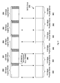
- FIG. 6 is a block diagram showing an exemplary FC (Fibre Channel) frame according to various embodiments of the present invention.
- the FC frame 602 comprises five high level sections 604 , 606 , 608 , 610 and 612 .
- the first high level section, called the start-of-frame delimiter 604 usually comprises 4 bytes that mark the beginning of the frame.
- the next high level section, called frame header 606 usually comprises 24 bytes that contain addressing information, sequence information, exchange information, and various control flags associated with the frame.
- a detailed view of the frame header 604 is shown in the block 614 .
- the frame header contains a reserved bit 615 .
- This bit is pre-set with values to differentiate a frame containing padding data from a frame containing real data to be stored. For example, if the reserved bit is set as one (1), that indicates the frame is a padded data frame or a control frame containing padding data, and if the bit is set as zero (0), the frame will be identified as a data frame comprising real data to be stored in the disk drive. It should be understood that using a reserved bit is one exemplary mechanism of informing the target device whether the frame payload contains padded or real data and embodiments of the invention are not so limited, but can employ other mechanism to accomplish the same.
- the initial Write command sent to the drive can be enhanced to indicate how many “first pad bytes” and “last pad bytes” should remain when logical sectors of data are written into the drive.
- D_ID destination identifier
- S_ID source identifier
- SOURCE_ID 618 is a 24-bit address that indicates the FC port that transmitted the frame.
- the next high level section 608 contains the actual data packaged within the FC frame.
- the actual data packaged within the frame comprises padding data instead of real data to be written.
- the data payload also contains encapsulating protocol information that is being transferred according to a higher-level protocol, such as IP and SCSI.
- FIG. 6 shows four basic types of data payload layouts 626 , 627 , 628 and 629 used for data transfer according to the SCSI protocol.
- the first format 626 is used to send a SCSI command from an initiator to a target.
- the FCP_LUN field 630 comprises an 8-byte address that may, in certain implementations, specify a particular SCSI-bus adapter, a target device associated with that SCSI-bus adapter, and a logical unit number (“LUN”) corresponding to a logical device associated with the specified target SCSI device that together represent the target for the FCP_CMND.
- the FCP_LUN field 630 contains an index or reference number that can be used by the target FC adapter to determine the SCSI-bus adapter, a target device associated with that SCSI-bus adapter, and a LUN corresponding to a logical device associated with the specified target SCSI device.
- An actual SCSI command such as a SCSI read or write I/O command, is contained within the 16 -byte field FCP_CDB 632 .
- the second type of data payload format 627 shown in FIG. 6 is called the FCP_XFER_RDY layout.
- This data payload format is used to transfer a SCSI notification from the target to the initiator when the target is prepared to begin receiving or sending data.
- the third type of data payload format 628 shown in FIG. 6 is the FCP_DATA format.
- the FCP_DATA format is used for transferring the actual data that is being read from, or written to, a data storage device as a result of execution of a SCSI I/O transaction.
- the actual data can be either padding data or real data from a logical sector to be written into the disk drive. If the packaged data is padding data, the reserved bit in the frame header will be set as 1 to indicate this frame is a padded data frame or control frame. In contrast, if the packaged data is data to be stored in the disk, the reserved bit in the frame header will be set as 0 to indicate the frame is a real data frame.
- the final data payload format 629 shown in FIG. 6 is called the FCP_RSP layout, used to transfer SCSI status as well as other FCP status information from the target back to the initiator upon completion of the I/O transaction.
- the bridge writes the first frame that contains padding data 505 a to the disk drive.
- the drive can determine whether this frame is a real data frame or padded data frame based on the reserved bit in the frame header. After determining the first frame only contains padded data, the drive disables writing such data into the storage device according to one embodiment of the present invention. This can be accomplished by initiating writes associated with the padded data but masking the corresponding bytes to ensure the unmodified data portion, such as 506 in FIG. 5 , is not corrupted or overwritten.
- the drive reads the data portion 506 from the sector 502 a and replaces the padded data 505 a in the first frame with the unmodified data portion 506 before initiating the writes of actual data of sector 504 , along with the unmodified data 506 , into the boundary sector 502 a.
- the second frame is received at the disk drive.
- the drive determines whether this frame is a real data frame based on the reserved bit.
- the data packaged therein i.e., the 520 bytes of actual data in sector 504
- the drive may successively receive multiple data frames comprising a number of logical sectors of data. In that case, the drive can continue the writes of these logical sectors until it receives a control frame comprising padded data again, such as the third frame received at step 516 .
- the third frame is processed in a similar way to processing the first control frame as described above.
- the drive can perform writes of those logical sectors data directly into the disk continuously without waiting to read unmodified data from the physical sectors, thereby enhancing the performance at no cost of storage capacity.
- FCP is used in the above description an example of the transport protocol between the initiator and target device, and embodiments of the invention are not so restricted. Instead, many other types of protocols that can be used for communications between the initiator and target device are supported by various embodiments of the present invention.
- FIG. 7 is a block diagram showing an exemplary hardware configuration for sector remapping according to various embodiments of the present invention.
- a storage bridge 710 is employed for translating or mapping logical sectors, such as 520-byte sectors 704 , into physical sectors, such as 512-byte sectors 702 .
- the bridge 710 can be coupled to a SATA disk drive as a separate component in the system.
- the bridge 710 is integrated into the disk drive 700 .
- the bridge 710 is also configured to communicate with host servers (not shown) where the enterprise storage applications 730 reside over a network 720 that supports different transport protocols such as FC protocols.
- the storage bridge 710 is a chip or circuit board, such as an ASIC (Application Specific Integrated Circuit), with a built-in processor (e.g., processor 716 in FIG. 7 ) to execute pre-programmed software code stored in the memory space (e.g., memory 718 in FIG. 7 ) of the bridge.
- the software code pre-programmed in the bridge 710 includes programs or computer-readable instructions for performing sector remapping algorithms.
- the bridge 710 comprises a functional module for sector remapping 712 and a functional module for data transmission 714 .
- the sector remapping module 712 also referred as a sector translator, is configured to perform sector remapping algorithms, such as the various algorithms described above in connection with FIGS. 3 a - b, 4 a - c. For example, if the sector mapping module 712 is configured to perform the sector mapping algorithm illustrated in FIG. 5 , the 520-byte sectors 704 received at the bridge 710 will be written into the disk drives 700 , along with necessary padded data, via a number of frames 706 .
- the data transmission module or data transmitter 714 is configured to transfer data through the frames into the disk drive.
- the sector translator 712 and data transmitter 714 are shown as separate units in FIG. 7 , it should be understood that they can be one integrated unit.
- Both functional modules can be implemented as pre-programmed computer-readable instructions stored in the memory 718 and executable by the processor 716 in the bridge 710 in FIG. 7 .
- the bridge 710 By use of the bridge 710 , logical sectors can be mapped into physical sectors to facilitate writing data into disk drives 700 .
- the disk drives 700 are illustrated as SATA disks, although it should be understood that the applicability of the present invention is not so limited.
- the present invention may be implemented with any other storage devices in need of sector remapping mechanisms.
- the storage disks follow standard configurations and can be customized by different vendors to provide additional features or accommodate their customers' needs.
- the disk drives 700 need to be modified to support the write operations 512 - 516 as described above.
- the disk drive 700 is configured to include additional software programs for determining whether a received frame is a real data frame or a padded data frame, and further, either disabling the writing of padded data or replacing the padded data with unmodified data in the disk sectors.
- the methods, processes or steps described herein may constitute one or more programs made up of machine-executable or computer-executable instructions.
- the above description particularly with reference to the steps and flow charts in FIGS. 3 a, 3 b, 4 a and 5 , enables one skilled in the art to develop such programs, including such instructions to carry out the operations represented by logical blocks on suitably-configured processors.
- the machine-executable instructions may be written in a computer programming language or may be embodied in firmware logic or in hardware circuitry. If written in a programming language conforming to a recognized standard, such instructions can be executed on a variety of hardware platforms for interfacing with a variety of operating systems.
Abstract
Description
Claims (45)
Priority Applications (1)
| Application Number | Priority Date | Filing Date | Title |
|---|---|---|---|
| US12/401,548 US8046533B2 (en) | 2009-03-10 | 2009-03-10 | System and method for sector remapping |
Applications Claiming Priority (1)
| Application Number | Priority Date | Filing Date | Title |
|---|---|---|---|
| US12/401,548 US8046533B2 (en) | 2009-03-10 | 2009-03-10 | System and method for sector remapping |
Publications (2)
| Publication Number | Publication Date |
|---|---|
| US20100232049A1 US20100232049A1 (en) | 2010-09-16 |
| US8046533B2 true US8046533B2 (en) | 2011-10-25 |
Family
ID=42730504
Family Applications (1)
| Application Number | Title | Priority Date | Filing Date |
|---|---|---|---|
| US12/401,548 Expired - Fee Related US8046533B2 (en) | 2009-03-10 | 2009-03-10 | System and method for sector remapping |
Country Status (1)
| Country | Link |
|---|---|
| US (1) | US8046533B2 (en) |
Cited By (16)
| Publication number | Priority date | Publication date | Assignee | Title |
|---|---|---|---|---|
| US20110113234A1 (en) * | 2009-11-11 | 2011-05-12 | International Business Machines Corporation | User Device, Computer Program Product and Computer System for Secure Network Storage |
| US20110125977A1 (en) * | 2009-11-20 | 2011-05-26 | Karr Christopher P | Aligning data storage device partition to boundary of physical data sector |
| US20130054979A1 (en) * | 2011-08-30 | 2013-02-28 | Microsoft Corporation | Sector map-based rapid data encryption policy compliance |
| US20130054916A1 (en) * | 2011-08-26 | 2013-02-28 | International Business Machines Corporation | Blocked based end-to-end data protection for extended count key data (eckd) |
| US8988805B1 (en) | 2014-03-26 | 2015-03-24 | Toshiba Global Commerce Solutions Holdings Corporation | Method for clipping hard drives while preserving full actuator arm movement |
| US8996839B1 (en) | 2012-01-23 | 2015-03-31 | Western Digital Technologies, Inc. | Data storage device aligning partition to boundary of sector when partition offset correlates with offset of write commands |
| US9063838B1 (en) | 2012-01-23 | 2015-06-23 | Western Digital Technologies, Inc. | Data storage device shifting data chunks of alignment zone relative to sector boundaries |
| US9281009B1 (en) | 2014-12-18 | 2016-03-08 | Western Digital Technologies, Inc. | Data storage device employing variable size interleave written track segments |
| US9430664B2 (en) | 2013-05-20 | 2016-08-30 | Microsoft Technology Licensing, Llc | Data protection for organizations on computing devices |
| US20160364141A1 (en) * | 2015-06-12 | 2016-12-15 | Phison Electronics Corp. | Memory management method, memory control circuit unit, and memory storage apparatus |
| US9825945B2 (en) | 2014-09-09 | 2017-11-21 | Microsoft Technology Licensing, Llc | Preserving data protection with policy |
| US9853812B2 (en) | 2014-09-17 | 2017-12-26 | Microsoft Technology Licensing, Llc | Secure key management for roaming protected content |
| US9853820B2 (en) | 2015-06-30 | 2017-12-26 | Microsoft Technology Licensing, Llc | Intelligent deletion of revoked data |
| US9900325B2 (en) | 2015-10-09 | 2018-02-20 | Microsoft Technology Licensing, Llc | Passive encryption of organization data |
| US9900295B2 (en) | 2014-11-05 | 2018-02-20 | Microsoft Technology Licensing, Llc | Roaming content wipe actions across devices |
| US10615967B2 (en) | 2014-03-20 | 2020-04-07 | Microsoft Technology Licensing, Llc | Rapid data protection for storage devices |
Families Citing this family (4)
| Publication number | Priority date | Publication date | Assignee | Title |
|---|---|---|---|---|
| KR101854200B1 (en) * | 2011-04-27 | 2018-06-20 | 시게이트 테크놀로지 엘엘씨 | Method for writing data on storage medium and storage apparatus applying the same |
| US9070378B2 (en) * | 2012-10-10 | 2015-06-30 | Seagate Technology Llc | Partial write system |
| US9842622B1 (en) * | 2014-12-23 | 2017-12-12 | Western Digital Technologies, Inc. | Data storage device having improved read failure tolerance |
| US10574270B1 (en) * | 2016-11-09 | 2020-02-25 | Seagate Technology Llc | Sector management in drives having multiple modulation coding |
Citations (7)
| Publication number | Priority date | Publication date | Assignee | Title |
|---|---|---|---|---|
| US6191712B1 (en) * | 1999-06-28 | 2001-02-20 | International Business Machines Corporation | Circuit for aligning logical sectors with physical sectors in a disk storage system |
| US20080016275A1 (en) * | 2003-01-13 | 2008-01-17 | Donia Sebastian | Allocation-unit-based virtual formatting methods and devices employing allocation-unit-based virtual formatting methods |
| US20080028157A1 (en) * | 2003-01-13 | 2008-01-31 | Steinmetz Joseph H | Global shared memory switch |
| US20080052728A1 (en) * | 2003-01-13 | 2008-02-28 | Steinmetz Joseph H | Method and interface for access to memory within a first electronic device by a second electronic device |
| US20080077763A1 (en) * | 2003-01-13 | 2008-03-27 | Steinmctz Joseph H | Method and system for efficient queue management |
| US20080162811A1 (en) * | 2003-01-13 | 2008-07-03 | Emulex Design And Manufacturing Corporation | Alignment-unit-based virtual formatting methods and devices employing the methods |
| US20090313426A1 (en) * | 2008-06-12 | 2009-12-17 | Seagate Technology, Llc | Buffer Management for Increased Write Speed in Large Sector Data Storage Device |
-
2009
- 2009-03-10 US US12/401,548 patent/US8046533B2/en not_active Expired - Fee Related
Patent Citations (8)
| Publication number | Priority date | Publication date | Assignee | Title |
|---|---|---|---|---|
| US6191712B1 (en) * | 1999-06-28 | 2001-02-20 | International Business Machines Corporation | Circuit for aligning logical sectors with physical sectors in a disk storage system |
| US20080016275A1 (en) * | 2003-01-13 | 2008-01-17 | Donia Sebastian | Allocation-unit-based virtual formatting methods and devices employing allocation-unit-based virtual formatting methods |
| US20080028157A1 (en) * | 2003-01-13 | 2008-01-31 | Steinmetz Joseph H | Global shared memory switch |
| US20080052728A1 (en) * | 2003-01-13 | 2008-02-28 | Steinmetz Joseph H | Method and interface for access to memory within a first electronic device by a second electronic device |
| US20080077763A1 (en) * | 2003-01-13 | 2008-03-27 | Steinmctz Joseph H | Method and system for efficient queue management |
| US20080162811A1 (en) * | 2003-01-13 | 2008-07-03 | Emulex Design And Manufacturing Corporation | Alignment-unit-based virtual formatting methods and devices employing the methods |
| US7801120B2 (en) * | 2003-01-13 | 2010-09-21 | Emulex Design & Manufacturing Corporation | Method and system for efficient queue management |
| US20090313426A1 (en) * | 2008-06-12 | 2009-12-17 | Seagate Technology, Llc | Buffer Management for Increased Write Speed in Large Sector Data Storage Device |
Cited By (25)
| Publication number | Priority date | Publication date | Assignee | Title |
|---|---|---|---|---|
| US20110113234A1 (en) * | 2009-11-11 | 2011-05-12 | International Business Machines Corporation | User Device, Computer Program Product and Computer System for Secure Network Storage |
| US8527749B2 (en) * | 2009-11-11 | 2013-09-03 | International Business Machines Corporation | User device, computer program product and computer system for system for secure network storage |
| US20110125977A1 (en) * | 2009-11-20 | 2011-05-26 | Karr Christopher P | Aligning data storage device partition to boundary of physical data sector |
| US8285965B2 (en) * | 2009-11-20 | 2012-10-09 | Western Digital Technologies, Inc. | Aligning data storage device partition to boundary of physical data sector |
| US8527724B2 (en) * | 2011-08-26 | 2013-09-03 | International Business Machines Corporation | Blocked based end-to-end data protection for extended count key data (ECKD) |
| US20130054916A1 (en) * | 2011-08-26 | 2013-02-28 | International Business Machines Corporation | Blocked based end-to-end data protection for extended count key data (eckd) |
| US20150033039A1 (en) * | 2011-08-30 | 2015-01-29 | Microsoft Corporation | Sector map-based rapid data encryption policy compliance |
| US8874935B2 (en) * | 2011-08-30 | 2014-10-28 | Microsoft Corporation | Sector map-based rapid data encryption policy compliance |
| US9740639B2 (en) * | 2011-08-30 | 2017-08-22 | Microsoft Technology Licensing, Llc | Map-based rapid data encryption policy compliance |
| US9477614B2 (en) * | 2011-08-30 | 2016-10-25 | Microsoft Technology Licensing, Llc | Sector map-based rapid data encryption policy compliance |
| US20130054979A1 (en) * | 2011-08-30 | 2013-02-28 | Microsoft Corporation | Sector map-based rapid data encryption policy compliance |
| US20170004094A1 (en) * | 2011-08-30 | 2017-01-05 | Microsoft Technology Licensing, Llc | Map-Based Rapid Data Encryption Policy Compliance |
| US8996839B1 (en) | 2012-01-23 | 2015-03-31 | Western Digital Technologies, Inc. | Data storage device aligning partition to boundary of sector when partition offset correlates with offset of write commands |
| US9063838B1 (en) | 2012-01-23 | 2015-06-23 | Western Digital Technologies, Inc. | Data storage device shifting data chunks of alignment zone relative to sector boundaries |
| US9430664B2 (en) | 2013-05-20 | 2016-08-30 | Microsoft Technology Licensing, Llc | Data protection for organizations on computing devices |
| US10615967B2 (en) | 2014-03-20 | 2020-04-07 | Microsoft Technology Licensing, Llc | Rapid data protection for storage devices |
| US8988805B1 (en) | 2014-03-26 | 2015-03-24 | Toshiba Global Commerce Solutions Holdings Corporation | Method for clipping hard drives while preserving full actuator arm movement |
| US9825945B2 (en) | 2014-09-09 | 2017-11-21 | Microsoft Technology Licensing, Llc | Preserving data protection with policy |
| US9853812B2 (en) | 2014-09-17 | 2017-12-26 | Microsoft Technology Licensing, Llc | Secure key management for roaming protected content |
| US9900295B2 (en) | 2014-11-05 | 2018-02-20 | Microsoft Technology Licensing, Llc | Roaming content wipe actions across devices |
| US9281009B1 (en) | 2014-12-18 | 2016-03-08 | Western Digital Technologies, Inc. | Data storage device employing variable size interleave written track segments |
| US20160364141A1 (en) * | 2015-06-12 | 2016-12-15 | Phison Electronics Corp. | Memory management method, memory control circuit unit, and memory storage apparatus |
| US10824340B2 (en) * | 2015-06-12 | 2020-11-03 | Phison Electronics Corp. | Method for managing association relationship of physical units between storage area and temporary area, memory control circuit unit, and memory storage apparatus |
| US9853820B2 (en) | 2015-06-30 | 2017-12-26 | Microsoft Technology Licensing, Llc | Intelligent deletion of revoked data |
| US9900325B2 (en) | 2015-10-09 | 2018-02-20 | Microsoft Technology Licensing, Llc | Passive encryption of organization data |
Also Published As
| Publication number | Publication date |
|---|---|
| US20100232049A1 (en) | 2010-09-16 |
Similar Documents
| Publication | Publication Date | Title |
|---|---|---|
| US8046533B2 (en) | System and method for sector remapping | |
| US8458381B2 (en) | Processing host transfer requests for direct block access storage devices | |
| US8296480B2 (en) | Context execution in a media controller architecture | |
| KR101252903B1 (en) | Allocation-unit-based virtual formatting methods and devices employing allocation-unit-based virtual formatting methods | |
| US8762681B2 (en) | Blocked based end-to-end data protection for extended count key data (ECKD) | |
| US7475279B2 (en) | Data storage system, data storage control device, and write error diagnosis method for disks thereof | |
| JP2006134064A (en) | Storage control apparatus and method for detecting writing error in storage medium | |
| US7861036B2 (en) | Double degraded array protection in an integrated network attached storage device | |
| US7774575B2 (en) | Integrated circuit capable of mapping logical block address data across multiple domains | |
| US20090187730A1 (en) | Mainframe storage controller and mainframe volume virtualization method | |
| US7769948B2 (en) | Virtual profiles for storage-device array encoding/decoding | |
| US20180052632A1 (en) | Storage system and storage control method | |
| US8327043B2 (en) | Buffer management device which manages buffer transfer, storage apparatus comprising the same device, and buffer management method | |
| US20110022793A1 (en) | Systems And Methods For Accessing Hard Disk Drives | |
| US20180107546A1 (en) | Data storage system with virtual blocks and raid and management method thereof | |
| JP2007524932A (en) | Method, system, and program for generating parity data | |
| US20060277326A1 (en) | Data transfer system and method | |
| US6950905B2 (en) | Write posting memory interface with block-based read-ahead mechanism | |
| US9921770B1 (en) | Extending fixed block architecture device access over ficon using transport mode protocol | |
| US10466918B1 (en) | Large size fixed block architecture device support over FICON channel connections | |
| JP2001256001A (en) | Disk array device | |
| JP2007179084A (en) | Disk device, and method of transferring data written in disk |
Legal Events
| Date | Code | Title | Description |
|---|---|---|---|
| AS | Assignment |
Owner name: EMULEX DESIGN & MANUFACTURING CORPORATION, CALIFOR Free format text: ASSIGNMENT OF ASSIGNORS INTEREST;ASSIGNORS:KOMPELLA, MURTHY;STEINMETZ, JOSEPH H.;AYALASOMAYAJULA, NARAYAN;REEL/FRAME:022685/0425 Effective date: 20090505 |
|
| ZAAA | Notice of allowance and fees due |
Free format text: ORIGINAL CODE: NOA |
|
| ZAAB | Notice of allowance mailed |
Free format text: ORIGINAL CODE: MN/=. |
|
| STCF | Information on status: patent grant |
Free format text: PATENTED CASE |
|
| AS | Assignment |
Owner name: EMULEX CORPORATION, CALIFORNIA Free format text: ASSIGNMENT OF ASSIGNORS INTEREST;ASSIGNOR:EMULEX DESIGN AND MANUFACTURING CORPORATION;REEL/FRAME:032087/0842 Effective date: 20131205 |
|
| FPAY | Fee payment |
Year of fee payment: 4 |
|
| AS | Assignment |
Owner name: AVAGO TECHNOLOGIES GENERAL IP (SINGAPORE) PTE. LTD Free format text: ASSIGNMENT OF ASSIGNORS INTEREST;ASSIGNOR:EMULEX CORPORATION;REEL/FRAME:036942/0213 Effective date: 20150831 |
|
| AS | Assignment |
Owner name: BANK OF AMERICA, N.A., AS COLLATERAL AGENT, NORTH CAROLINA Free format text: PATENT SECURITY AGREEMENT;ASSIGNOR:AVAGO TECHNOLOGIES GENERAL IP (SINGAPORE) PTE. LTD.;REEL/FRAME:037808/0001 Effective date: 20160201 Owner name: BANK OF AMERICA, N.A., AS COLLATERAL AGENT, NORTH Free format text: PATENT SECURITY AGREEMENT;ASSIGNOR:AVAGO TECHNOLOGIES GENERAL IP (SINGAPORE) PTE. LTD.;REEL/FRAME:037808/0001 Effective date: 20160201 |
|
| AS | Assignment |
Owner name: AVAGO TECHNOLOGIES GENERAL IP (SINGAPORE) PTE. LTD., SINGAPORE Free format text: TERMINATION AND RELEASE OF SECURITY INTEREST IN PATENTS;ASSIGNOR:BANK OF AMERICA, N.A., AS COLLATERAL AGENT;REEL/FRAME:041710/0001 Effective date: 20170119 Owner name: AVAGO TECHNOLOGIES GENERAL IP (SINGAPORE) PTE. LTD Free format text: TERMINATION AND RELEASE OF SECURITY INTEREST IN PATENTS;ASSIGNOR:BANK OF AMERICA, N.A., AS COLLATERAL AGENT;REEL/FRAME:041710/0001 Effective date: 20170119 |
|
| AS | Assignment |
Owner name: AVAGO TECHNOLOGIES INTERNATIONAL SALES PTE. LIMITE Free format text: MERGER;ASSIGNOR:AVAGO TECHNOLOGIES GENERAL IP (SINGAPORE) PTE. LTD.;REEL/FRAME:047422/0464 Effective date: 20180509 |
|
| AS | Assignment |
Owner name: AVAGO TECHNOLOGIES INTERNATIONAL SALES PTE. LIMITE Free format text: CORRECTIVE ASSIGNMENT TO CORRECT THE EXECUTION DATE PREVIOUSLY RECORDED AT REEL: 047422 FRAME: 0464. ASSIGNOR(S) HEREBY CONFIRMS THE MERGER;ASSIGNOR:AVAGO TECHNOLOGIES GENERAL IP (SINGAPORE) PTE. LTD.;REEL/FRAME:048883/0702 Effective date: 20180905 |
|
| MAFP | Maintenance fee payment |
Free format text: PAYMENT OF MAINTENANCE FEE, 8TH YEAR, LARGE ENTITY (ORIGINAL EVENT CODE: M1552); ENTITY STATUS OF PATENT OWNER: LARGE ENTITY Year of fee payment: 8 |
|
| FEPP | Fee payment procedure |
Free format text: MAINTENANCE FEE REMINDER MAILED (ORIGINAL EVENT CODE: REM.); ENTITY STATUS OF PATENT OWNER: LARGE ENTITY |
|
| LAPS | Lapse for failure to pay maintenance fees |
Free format text: PATENT EXPIRED FOR FAILURE TO PAY MAINTENANCE FEES (ORIGINAL EVENT CODE: EXP.); ENTITY STATUS OF PATENT OWNER: LARGE ENTITY |
|
| STCH | Information on status: patent discontinuation |
Free format text: PATENT EXPIRED DUE TO NONPAYMENT OF MAINTENANCE FEES UNDER 37 CFR 1.362 |
|
| FP | Lapsed due to failure to pay maintenance fee |
Effective date: 20231025 |