US8061539B2 - Storage system with accessory mounting rail - Google Patents
Storage system with accessory mounting rail Download PDFInfo
- Publication number
- US8061539B2 US8061539B2 US12/132,432 US13243208A US8061539B2 US 8061539 B2 US8061539 B2 US 8061539B2 US 13243208 A US13243208 A US 13243208A US 8061539 B2 US8061539 B2 US 8061539B2
- Authority
- US
- United States
- Prior art keywords
- supports
- mounting
- storage
- pair
- storage system
- Prior art date
- Legal status (The legal status is an assumption and is not a legal conclusion. Google has not performed a legal analysis and makes no representation as to the accuracy of the status listed.)
- Active, expires
Links
Images


Classifications
-
- A—HUMAN NECESSITIES
- A47—FURNITURE; DOMESTIC ARTICLES OR APPLIANCES; COFFEE MILLS; SPICE MILLS; SUCTION CLEANERS IN GENERAL
- A47B—TABLES; DESKS; OFFICE FURNITURE; CABINETS; DRAWERS; GENERAL DETAILS OF FURNITURE
- A47B47/00—Cabinets, racks or shelf units, characterised by features related to dismountability or building-up from elements
- A47B47/02—Cabinets, racks or shelf units, characterised by features related to dismountability or building-up from elements made of metal only
- A47B47/021—Racks or shelf units
-
- A—HUMAN NECESSITIES
- A47—FURNITURE; DOMESTIC ARTICLES OR APPLIANCES; COFFEE MILLS; SPICE MILLS; SUCTION CLEANERS IN GENERAL
- A47B—TABLES; DESKS; OFFICE FURNITURE; CABINETS; DRAWERS; GENERAL DETAILS OF FURNITURE
- A47B57/00—Cabinets, racks or shelf units, characterised by features for adjusting shelves or partitions
- A47B57/04—Cabinets, racks or shelf units, characterised by features for adjusting shelves or partitions with means for adjusting the inclination of the shelves
-
- A—HUMAN NECESSITIES
- A47—FURNITURE; DOMESTIC ARTICLES OR APPLIANCES; COFFEE MILLS; SPICE MILLS; SUCTION CLEANERS IN GENERAL
- A47B—TABLES; DESKS; OFFICE FURNITURE; CABINETS; DRAWERS; GENERAL DETAILS OF FURNITURE
- A47B57/00—Cabinets, racks or shelf units, characterised by features for adjusting shelves or partitions
- A47B57/06—Cabinets, racks or shelf units, characterised by features for adjusting shelves or partitions with means for adjusting the height of the shelves
- A47B57/08—Cabinets, racks or shelf units, characterised by features for adjusting shelves or partitions with means for adjusting the height of the shelves consisting of grooved or notched ledges, uprights or side walls
- A47B57/10—Cabinets, racks or shelf units, characterised by features for adjusting shelves or partitions with means for adjusting the height of the shelves consisting of grooved or notched ledges, uprights or side walls the grooved or notched parts being the side walls or uprights themselves
-
- A—HUMAN NECESSITIES
- A47—FURNITURE; DOMESTIC ARTICLES OR APPLIANCES; COFFEE MILLS; SPICE MILLS; SUCTION CLEANERS IN GENERAL
- A47B—TABLES; DESKS; OFFICE FURNITURE; CABINETS; DRAWERS; GENERAL DETAILS OF FURNITURE
- A47B96/00—Details of cabinets, racks or shelf units not covered by a single one of groups A47B43/00 - A47B95/00; General details of furniture
Definitions
- the present invention relates to storage systems, and more specifically to a storage system including a rail securable to the system in multiple orientations and onto which a number of different supporting members can be releasably positioned in various configurations.
- the storage system should include components that are formed to be able to be secured to the storage system structure in different orientations, and to have different types of storage containers attached directly to them without additional modifications or supporting structures to eliminate the cleaning and assembly issues associated with prior art storage systems.
- a modular storage system in which the system has a base structure formed of separate modules that can be configured as desired for the particular environment in which the system is to be used.
- the modules are assembled from frames including supports that can have various additional structures secured thereto, such as shelves, storage bin rails, slat wall pegs, hangers and other support members.
- the supports can also have other structures secured to the supports, such as work surfaces and corresponding features, such as lighting and shelves or other storages bins disposed under the work surface.
- the modules can also be configured to enable one or more of the frames making up the modules to be movable with respect to the fixed frames.
- the storage system includes a rail support structure that is attachable to the supports of the frames in each module.
- the rail is configured to enable various types of storage structures to be engaged and directly supported by the rail, including both storage bins of various sizes, and slat wall accessories.
- the rail can be attached to the supports for the modules in various orientations to enable the storage containers held by the rails to be disposed in various configurations that allow for the most efficient use of the storage space provided within the storage system, as well as easiest access for the user.
- FIG. 1 is an isometric view of the storage system constructed according to the present invention
- FIG. 2 is an isometric view of a first embodiment of storage module of the storage system of FIG. 1 ;
- FIG. 3 is a partially broken away, front plan view of a second embodiment of a storage module of the storage module of FIG. 1 ;
- FIG. 4 is a side plan view of the storage module of FIG. 2 ;
- FIG. 5 is a partially broken away, side plan view of an upper guide assembly of the storage module of FIG. 4 ;
- FIG. 6 is a partially broken away, side plan view of a lower guide assembly of the storage module of FIG. 4 ;
- FIG. 7 is an isometric view of a first embodiment of a mounting rail for the storage module of FIG. 1 ;
- FIG. 8 is an exploded, isometric view of the first embodiment of the mounting rail of FIG. 7 ;
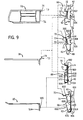
- FIG. 9 is a side plan view of three embodiments of the mounting rail of FIG. 7 ;
- FIG. 10 is an isometric view of a first embodiment of the first embodiment of the mounting rail of FIG. 7 ;
- FIG. 11 is an isomeric view of a second embodiment of the mounting rail of FIG. 7 ;
- FIG. 12 is an isometric view of a third embodiment of the mounting rail of FIG. 7 ;
- FIG. 13 is an isometric view of a shelf secured to the storage module of FIG. 2 ;
- FIG. 14 is an isometric view of the second embodiment of the mounting rail secured to the storage module of FIG. 2 ;
- FIG. 15 is an exploded, isometric view of the second embodiment of the mounting rail of FIG. 14 .
- FIG. 1 a storage system constructed according to the present invention is indicated generally at 10 in FIG. 1 .
- the storage system 10 is formed of a number of modules 12 and that can be secured to one another in various configurations depending upon the configuration of the space within which the storage system 10 is to be disposed, similar to that disclosed in U.S. Pat. No. 5,943,967, which is incorporated herein by reference in its entirety.
- each module 12 can be formed with a number of individual frames 14 constituting the module 12 .
- the modules 12 are formed from between one and three separate frames 14 connected to one another utilizing suitable connecting or fastening means, but other numbers of frames 14 can also be utilized as necessary or desired.
- Each frame 14 is designed to hold and/or accommodate a number of varying storage units 16 thereon, including, but not limited to, hangers or hooks 18 , storage bins 20 , and pegs 22 .
- Each of these various storage units 16 is capable of holding a number of different items (not shown) therein in a manner which allows for easy access to the items by an individual.
- each frame 14 is formed with a top member 36 and a bottom member 38 between which are secured two or more vertical supports 40 that can be joined by horizontal supports 39 .
- the top member 36 can also function as a canopy for each individual module 12 in order to provide a more aesthetically pleasing appearance to the module 12 as well as to provide a dust cover to the modules 12 .
- the supports 40 include a number of apertures 42 spaced along the length of the supports 40 in order to enable various structures to be secured to the supports 40 utilizing the apertures 42 .
- the supports 40 can be U-shaped, with the apertures 42 disposed on the opposed surfaces of the support 40 , or can be square or rectangular in shape, as in FIGS. 10 and 11 , with apertures 42 on each surface of the support 40 .
- the apertures 42 can take various shapes to conform to the items, such as vertically extending rectangular slots 42 a ( FIGS. 2 , 3 , 7 , 8 and 13 ), or as generally circular openings 42 b having a downwardly extending notch 42 c ( FIGS. 14-15 ).
- top member 36 , bottom member 38 and/or supports 40 of the frames 14 can be secured to the floor, the ceiling and/or a wall, such as by brackets 41 , or to various corner or end filler structures 44 in order to provide additional support to each frame 14 .
- the structure can also include various side supports 43 that provide additional support to the frame 14 , especially when a single fixed frame 14 is to be free-standing with various storage units 16 disposed on both sides of the particular fixed frame 14 .
- the side supports 43 can take numerous forms including expanded base supports 45 , or additional vertical supports 40 spaced forwardly from and connected to the supports 40 to which the storage units 16 are secured.
- the shelves 46 include a flat planar surface 50 extending between a pair of brackets 52 that are releasably engageable within the slots 42 a in the supports 40 to enable the shelves 46 to be positioned as desired without the need for any additional tools or fasteners.
- the shelves 46 can be designed to be secured to a given frame 14 in a generally horizontal position or in a downwardly inclined position with respect to the frame 14 depending on the use for the particular shelf 46 due the configuration of the brackets 52 secured to the sides of the shelf 46 .
- the brackets 52 include a body 102 that is secured to the shelf 46 , and three tabs 104 , 106 and 108 that extend outwardly from the body 102 to define corresponding recesses 110 , 112 and 114 between the tabs 104 , 106 and 108 and the body 102 .
- the tabs 104 and 106 are positioned on the body 102 such that when the tabs 104 and 106 are engaged within selected slots 42 a on the vertical supports 40 , the shelf is disposed in a flat, horizontal orientation. However, when the tabs 106 and 108 are engaged with the selected slots 42 a , the shelf 46 is disposed in a downwardly inclined orientation with regard to the vertical supports 40 that preferably is about seventeen degrees with regard to horizontal.
- the shelves 46 can be formed with an outer lip 53 on the surface 50 generally opposite the brackets 52 that enables the shelf 46 to retain items thereon even when positioned at an incline with respect to the frame 14 .
- FIG. 1 there also can be work surfaces 48 secured to the various frames 14 that include a flat planar surface 54 supported at opposite ends by a pair of brackets (not shown) that are engageable within the apertures 42 in the rails 40 similarly to the brackets 52 on the shelves 46 .
- the planar surface 54 can be formed to have an overall length equal to the length of one or multiple frames 14 , in order to provide the desired area for the work surface 48 .
- the planar surface 54 includes one or more chamfered corners 58 to minimize any interference by the work surface 48 with adjacent frames 14 or modules 12 of the storage system 10 , and to enable work surfaces 48 positioned in adjacent and/or perpendicular modules 12 to form a continuous work surface 48 between the modules 12 .
- the storage system 10 can also include end covers 78 positioned vertically along the various ends of each module 12 and secured to the vertical supports 40 to provide a more aesthetically pleasing appearance to the various modules 12 and the overall system 10 .
- These covers 78 can be formed to have a width equal to the width of a single module 12 or a pair of modules 12 depending upon the particular position for the cover 78 on the system 10 .
- FIG. 1 A preferred embodiment of the storage system 10 is illustrated in FIG. 1 as having frames 14 formed with two, three or four evenly spaced vertical supports 40 , enabling the frames 14 to accommodate shelves 46 and work surfaces 48 having an overall width approximately equal to the spacing of the vertical supports 40 forming the frames 14 .
- This allows the frames 14 and modules 12 of the system 10 to be optimized for utilization with various storage units 16 , such as storage bins 20 , having specified widths in order to enable the greatest number of storage units 16 to be mounted within a particular module 12 .
- certain modules 12 are formed from a number of fixed frames 14 secured to one another, but also including upper and lower guide tracks 24 and 26 secured to the upper member 36 and lower member 38 of each fixed frame 14 .
- the tracks 24 and 26 are configured to movably support one or more mobile frames 28 thereon.
- the mobile frames 28 are formed similarly to the fixed frames 14 with a pair of vertical supports 40 having apertures 42 formed therein, but include roller assemblies 30 disposed on upper and lower horizontal supports 39 of each mobile frame 28 and rotatably positioned within the tracks 24 and 26 on the fixed frames 14 .
- the roller assemblies 30 are engaged with the tracks 24 and 26 in a manner that allows the roller assemblies 30 to move within and/or along the respective track 24 and 26 to guide the movement of the mobile frame 28 with respect to the fixed frame 14 .
- the frames 28 also include handles 31 disposed on horizontal supports 39 secured between the vertical supports 40 forming each side of the mobile frame 28 .
- Each module 12 can include multiple mobile frames 28 attached to the tracks 24 and 26 separately from one another such that mobile frames 28 are movable independently with respect to each other. Further, the tracks 24 and 26 are constructed such that the mobile frames 28 secured thereto are positioned in front of the fixed frames 14 a sufficient distance such that the position and movement of the mobile frames 28 along the tracks 24 and 26 does not contact or otherwise interfere with those storage units 16 secured to the fixed frames 14 . Also, the upper member 36 and lower member 38 for the modules 12 can be designed to accommodate multiple pairs of spaced tracks 24 and 26 that are disposed in front of the fixed frames 14 , such that a number of mobile frames 28 can be disposed in front of the fixed frames 14 and one another.
- each mobile frame 28 can include a deceleration device 32 adjacent to the upper end of the mobile frame 28 , as best shown in FIGS. 1-5 .
- the deceleration device 32 extends laterally from the mobile frame 28 in order to engage a stop 34 positioned at each end of the fixed frames 14 forming the module 12 .
- the deceleration device 32 is resiliently biased to an extended position by a suitable biasing element or mechanism (not shown) such as a spring or gas cylinder, such that when the deceleration device 32 contacts the stop 34 , the biasing element is gradually compressed by continued movement of the mobile frame 28 and consequently slows the movement of the mobile frame 28 with regard to the fixed frames 14 . This prevents any sudden jarring stops for the mobile frame 28 which could cause the items held on the mobile frames 28 to become dislodged from within the storage units 16 located thereon, and/or damage to the mobile frames 28 .
- each frame 14 or 28 also includes one or more support rails 60 that are secured between each of the vertical supports 40 in the particular frame 14 or 28 .
- Each support rail 60 includes a lower portion 62 and an upper portion 64 that are each utilized to engage and hold various storage units 16 thereon.
- the lower portion 62 and upper portion 64 are formed as oppositely curved U-shaped portions of an integral rigid member 66 , such that when the rail 60 is secured to the vertical supports 40 , the lower portion 62 extends outwardly away from the supports 40 , while the upper portion 64 extends inwardly toward the supports 40 .
- each end of the upper portion 64 includes a mounting arrangement or an engagement bracket 68 that is releasably engageable with the slots or mounting structures 42 a formed in the supports 40 to mount the support rail 60 on the frame 14 or 28 where desired.
- the engagement brackets 68 enable the support rail 60 to be mounted to the vertical supports 40 in either a horizontal configuration or a downwardly inclined configuration, as best shown in FIGS. 4 and 9 .
- each bracket 68 is formed similarly to the bracket 52 used with the shelves 46 with a body or mounting arrangement 300 and three tabs or mounting members 302 , 304 and 306 extending outwardly therefrom in a direction opposite the upper portion 64 .
- the rail 60 When the tabs 302 and 304 are engaged with the selected slots 42 a on the supports 40 , the rail 60 is mounted in a horizontal orientation, and when the tabs 304 and 306 are secured to the selected slots 42 a , the rail 60 is oriented in a downwardly inclined position, preferably at an angle of seventeen degrees from horizontal.
- the upper portion 64 of the rail 60 includes a pair of opposed securing flanges or engagement structures 70 and 72 .
- the flange 70 is positioned adjacent and extends towards the lower portion 62
- the flange 72 is disposed on and preferably integrally formed with the opposite end of the upper portion 64 and extends away from the flange 70 .
- the flange 70 in conjunction with the portion of the rail 60 connecting the lower portion 62 and upper portion 64 and a planar exposed surface of the lower portion 62 , creates an attachment point for a an attachment flange 73 present on a number of different types of hooks 18 and slat wall pegs 22 to support and engage the hooks 18 and pegs 22 in either the horizontal or downwardly inclined positions. Further, because the flange 70 is preferably formed to be continuous across the entire length of the rail 60 , the number and type of hooks 18 and/or pegs 22 that can be secured to the rail 60 using the flange 70 can be varied as desired. As seen in FIG. 9 , the planar exposed surface of lower portion 62 extends beyond the engagement structure or flange 70 and defines a resting support in abutting relationship with a lower end of the storage elements 18 , 20 .
- the flange 72 provides an attachment point for a tab 74 disposed at the rear of a conventional storage bin 20 .
- the tab 74 on the bin 20 is engaged with the flange 72 , the lower end 76 of the rear surface of the bin 20 is positioned against the lower portion 62 , such that the rail 60 provides a stable support for the storage bin 20 when the rail 60 is in either the horizontal or downwardly inclined position.
- a stop structure defined by first and second stop structures 77 , 75 , respectively, is disposed at each end of both the flanges or engagement structures 70 and 72 in order to prevent the hooks 18 , pegs 22 and bins 20 from sliding off of either end of the flanges 70 and 72 .
- the stop structures 75 and 77 are integrally formed as parts of each securing engagement bracket 68 that are engaged with and extend through the rail 60 to secure each bracket 68 to the rail 60 .
- the stop structure 77 is located between the first and second engagement structures or flanges 72 and 70 .
- the stop structure 75 is located between the second engagement structure or flange 70 and the lower portion 62 .
- the stop structure 75 engages the portion of the hook 18 or peg 22 engaged with the flange 70
- the stop structure 77 engages the body of a bin 20 engaged with the flange 72
- the rigid member 66 including the lower portion 62 and the upper portion 64 , the securing engagement brackets 68 and the flanges 70 and 72 are preferably integrally formed with each other, to provide a support rail 60 that is simple to install and utilize in attaching and supporting storage units 16 in various configurations.
- the positioning of the rails 60 within each frame 14 and 28 can be varied as necessary in order to enable storage bins 20 , hooks 18 and pegs 22 of various shapes and sizes to be disposed in any desired configuration and in any arrangement along the rail 60 within each frame 14 and 28 .
- FIGS. 9 , 11 , 12 , 14 and 15 other embodiments for the rail 60 are illustrated.
- the engagement brackets 68 are omitted and the rigid member 66 is affixed in any suitable manner to a back panel 500 .
- the back panel 500 is formed of a generally rigid material, similar to the rigid member 66 , and that includes an upper section 502 secured to the upper portion 64 of the rigid member 66 and a lower section 504 secured to the lower portion 62 of the rigid member 66 .
- the back panel 500 also includes a central section 506 that is joined to a number of pins 510 .
- the pins 510 are formed similarly to the pins 402 for shelves 46 ′, with a shaft 512 extending through and connected to the central portion 506 , and a head 514 connected to the shaft 512 opposite the back panel 500 .
- the pins 510 enable the rail 560 to be secured to the vertical supports 40 including the openings 42 b and notches 42 c to position the rail 560 in a horizontal orientation, as best shown in FIG. 9 .
- the lower portion 62 of the rail 560 can be formed with other mounting structures 516 therein, such as apertures 518 that are engagable with securing tabs 520 disposed on U-shaped hooks 22 .
- the tabs 520 are formed in a base 524 for the hook 22 which also includes a locking aperture 526 disposed directly beneath the tab 520 and alignable with an opening 528 in the lower portion 62 of the rail 560 to receive a suitable locking member (not shown) therein which secured the hook 22 to the rail 560 .
- the rail 660 is formed similarly to the rail 560 , with the exception of the back panel 600 .
- the back panel 600 is formed with an upper section 602 and a lower section 604 that are each angled downwardly from perpendicular with regard to the central section 606 .
- the upper section 602 is formed with a length greater than that of the lower section 604 , such that the rigid member 66 is positioned in a downwardly inclined position with regard to the central portion 606 when affixed to the back member 600 .
- the rigid member 66 of the rail 660 is disposed in a downwardly inclined position with regard to horizontal that is similar to the orientation of the rail 60 in its downwardly inclined configuration.
- brackets 52 and 68 for holding the shelves 46 and rails 60 on the supports 40 can be formed with alternative engaging structures other than the tabs 104 - 108 , such as pins 402 , or any other suitable engaging structure.
Abstract
Description
Claims (13)
Priority Applications (5)
| Application Number | Priority Date | Filing Date | Title |
|---|---|---|---|
| US12/132,432 US8061539B2 (en) | 2007-06-04 | 2008-06-03 | Storage system with accessory mounting rail |
| MX2008007163A MX2008007163A (en) | 2007-06-04 | 2008-06-04 | Liftgate guide column cover and service access. |
| AU2008202461A AU2008202461A1 (en) | 2007-06-04 | 2008-06-04 | Storage system with accessory mounting rail |
| GB0810225A GB2449986A (en) | 2007-06-04 | 2008-06-04 | Storage system with accessory mounting rail |
| CA2633297A CA2633297C (en) | 2007-06-04 | 2008-06-04 | Storage system with accessory mounting rail |
Applications Claiming Priority (2)
| Application Number | Priority Date | Filing Date | Title |
|---|---|---|---|
| US94185007P | 2007-06-04 | 2007-06-04 | |
| US12/132,432 US8061539B2 (en) | 2007-06-04 | 2008-06-03 | Storage system with accessory mounting rail |
Publications (2)
| Publication Number | Publication Date |
|---|---|
| US20080296245A1 US20080296245A1 (en) | 2008-12-04 |
| US8061539B2 true US8061539B2 (en) | 2011-11-22 |
Family
ID=39638172
Family Applications (1)
| Application Number | Title | Priority Date | Filing Date |
|---|---|---|---|
| US12/132,432 Active 2029-06-18 US8061539B2 (en) | 2007-06-04 | 2008-06-03 | Storage system with accessory mounting rail |
Country Status (5)
| Country | Link |
|---|---|
| US (1) | US8061539B2 (en) |
| AU (1) | AU2008202461A1 (en) |
| CA (1) | CA2633297C (en) |
| GB (1) | GB2449986A (en) |
| MX (1) | MX2008007163A (en) |
Cited By (26)
| Publication number | Priority date | Publication date | Assignee | Title |
|---|---|---|---|---|
| US20110154744A1 (en) * | 2009-12-29 | 2011-06-30 | Brad Bowen | Modular living wall component and system |
| US20110168651A1 (en) * | 2010-01-13 | 2011-07-14 | Demco, Inc. | Shelving System and Components Thereof |
| US20130068710A1 (en) * | 2011-09-16 | 2013-03-21 | Gary Cearns | Rack For Horizontal Storage |
| US20140027394A1 (en) * | 2012-07-26 | 2014-01-30 | Prosteel Security Products Inc. | Modular safe interior |
| US20140048503A1 (en) * | 2012-08-20 | 2014-02-20 | Ace-Hinge Tech Co., Ltd. | Hanger panel and hanger device using the same |
| US20140104826A1 (en) * | 2010-02-18 | 2014-04-17 | Summit Plastics, Inc. | Modular merchandise display system |
| US8955271B2 (en) | 2012-09-17 | 2015-02-17 | Steelcase Inc. | Sliding door assembly |
| US20150136719A1 (en) * | 2013-11-18 | 2015-05-21 | Nexxspan Healthcare, Llc | Storage bin system |
| US20150230632A1 (en) * | 2014-02-17 | 2015-08-20 | Mid-West Metal Products Co., Inc. | End Cap for Variable Display Configurations |
| US9206827B2 (en) | 2012-11-20 | 2015-12-08 | Avery Dennison Corporation | Wall mount organization system |
| DE102015000272A1 (en) * | 2015-01-16 | 2016-07-21 | Gesa Form + Funktion Displaybau Gmbh | Presentation equipment, in particular of goods |
| USD767926S1 (en) | 2015-01-19 | 2016-10-04 | Target Brands, Inc. | Display shelf |
| US9468312B2 (en) * | 2015-01-19 | 2016-10-18 | Target Brands, Inc. | Display fixture with cantilevered shelf |
| US20170062255A1 (en) * | 2015-09-02 | 2017-03-02 | Daifuku Co., Ltd. | Storage Rack |
| US10093449B2 (en) * | 2015-04-23 | 2018-10-09 | Crrc Meishan Co., Ltd. | Double-surface contact tray loading base |
| US20190029416A1 (en) * | 2017-07-28 | 2019-01-31 | Zhi Qiang Lu | Heavy duty shelving assembly |
| US10306981B2 (en) | 2016-12-02 | 2019-06-04 | Altria Client Services Llc | Universal mounting system (UMS) and method of installing thereof |
| US10327551B1 (en) * | 2013-12-12 | 2019-06-25 | Sasha Johnson | Vertical shelf support bars having laterally spaced apart first support interfaces and second support interfaces recessed and laterally inside the first support interfaces |
| US10334970B2 (en) * | 2016-12-02 | 2019-07-02 | Altria Client Services Llc | Adaptive merchandising platform (AMP) mounting system and method of installing thereof |
| US10410544B1 (en) * | 2018-10-29 | 2019-09-10 | Imageworks Display And Marketing Group, Inc. | Merchandise display stand |
| US10433659B1 (en) * | 2018-05-18 | 2019-10-08 | Target Brands, Inc. | Interactive display unit |
| US10585413B2 (en) * | 2016-04-19 | 2020-03-10 | Robert Bosch Gmbh | Assembly workstation comprising position determination device |
| US10799041B1 (en) * | 2019-03-26 | 2020-10-13 | Tag Hardware Systems Ltd. | Wall mounted organizer rack |
| CN112690594A (en) * | 2019-10-22 | 2021-04-23 | 施耐宝公司 | Support for hanging containers |
| US20210316670A1 (en) * | 2020-04-10 | 2021-10-14 | Wesley Harkins | Toolbox |
| US11744387B1 (en) * | 2021-06-10 | 2023-09-05 | Diam Uk Ltd | Customizable product storage and display system |
Families Citing this family (18)
| Publication number | Priority date | Publication date | Assignee | Title |
|---|---|---|---|---|
| US8141724B2 (en) * | 2009-05-18 | 2012-03-27 | Metal Masters Foodservice Equipment Co., Inc. | Double sided bin holder assembly |
| US9185974B2 (en) | 2010-06-02 | 2015-11-17 | Steelcase Inc. | Frame type workstation configurations |
| US8689705B2 (en) | 2010-06-02 | 2014-04-08 | Steelcase, Inc. | Reconfigurable table assemblies |
| US8667908B2 (en) | 2010-06-02 | 2014-03-11 | Steelcase Inc. | Frame type table assemblies |
| US9210999B2 (en) | 2010-06-02 | 2015-12-15 | Steelcase Inc. | Frame type table assemblies |
| US8322669B2 (en) * | 2010-06-30 | 2012-12-04 | Akro-Mils, Inc. | Storage bin retainer member |
| CN102006757B (en) * | 2010-10-22 | 2012-10-03 | 华为技术有限公司 | Installation bracket |
| US8454036B2 (en) * | 2011-05-17 | 2013-06-04 | Apex Brands, Inc. | Tool kit mounting system |
| US8651029B2 (en) * | 2011-08-31 | 2014-02-18 | Target Brands, Inc. | Potting bench |
| WO2013158657A1 (en) * | 2012-04-18 | 2013-10-24 | Volcano Corporation | Integrated support structures for mobile medical systems |
| US9277814B2 (en) * | 2014-05-21 | 2016-03-08 | Aaron James Winker | Adjustable continuous shelf mounting systems and apparatuses related thereto |
| WO2016085977A1 (en) * | 2014-11-24 | 2016-06-02 | Tube Technology, Inc. | Snap-on platform for tubular shelving |
| US9713379B1 (en) * | 2016-01-24 | 2017-07-25 | Frank Tsai | Shelf supporting beam configuration for shelving apparatus |
| US10517392B2 (en) | 2016-05-13 | 2019-12-31 | Steelcase Inc. | Multi-tiered workstation assembly |
| WO2017197395A1 (en) | 2016-05-13 | 2017-11-16 | Steelcase Inc. | Multi-tiered workstation assembly |
| CN108783990A (en) * | 2018-07-17 | 2018-11-13 | 苏州科技大学 | A kind of architectural design drawing holding device fo |
| CN210471537U (en) * | 2019-05-10 | 2020-05-08 | 佛山市迪赛纳科技有限公司 | Bracket of storage rack |
| WO2021228199A1 (en) * | 2020-05-14 | 2021-11-18 | Hangzhou Great Star Industrial Co., Ltd. | Industrial rack |
Citations (38)
| Publication number | Priority date | Publication date | Assignee | Title |
|---|---|---|---|---|
| GB359010A (en) | 1929-09-30 | 1931-10-12 | Noel Joseph Poux | Improvements in or relating to separable fasteners |
| US3067882A (en) * | 1961-04-07 | 1962-12-11 | Tab Products Co | Suspension framework |
| US3182945A (en) * | 1963-08-29 | 1965-05-11 | M & D Store Fixtures Inc | Multi-angle bracket |
| US3248079A (en) * | 1963-12-30 | 1966-04-26 | Clark Equipment Co | Angularly adjustable shelf bracket |
| GB1261512A (en) | 1967-11-07 | 1972-01-26 | Keeles Of Hadleigh Ltd | Shelving |
| US4008873A (en) * | 1976-01-29 | 1977-02-22 | Emhart Industries, Inc. | Angularly adjustable shelf bracket |
| US4228906A (en) * | 1978-09-14 | 1980-10-21 | Kardex Systems, Inc. | Adjustable rail mounting assembly |
| US4307671A (en) * | 1980-05-05 | 1981-12-29 | The Kent Corporation | Merchandise shelving display |
| GB2088702A (en) | 1980-12-04 | 1982-06-16 | Westinghouse Electric Corp | Wall-hung support rails |
| US4377241A (en) | 1980-12-04 | 1983-03-22 | Westinghouse Electric Corp. | Pallet frame |
| US4378925A (en) * | 1981-03-10 | 1983-04-05 | Lingo Manufacturing Company | T-Bracket shelf assembly |
| US4401222A (en) * | 1981-06-08 | 1983-08-30 | Westinghouse Electric Corp. | Support rail |
| US4552272A (en) | 1984-04-11 | 1985-11-12 | Field Frank P | Display bin |
| DE3510330A1 (en) | 1985-03-22 | 1986-09-25 | Alois 7580 Bühl Wörner | Device for storing tools, in particular a storage rack for injection moulds |
| US4736997A (en) * | 1987-06-05 | 1988-04-12 | General Electric Company | Household refrigerator shelf assembly |
| EP0294608A1 (en) | 1987-06-08 | 1988-12-14 | Herman Miller, Inc. | Tool cabinet |
| US4809856A (en) | 1988-06-23 | 1989-03-07 | Spacesaver Corporation | Shelf divider |
| US5154388A (en) * | 1989-06-06 | 1992-10-13 | C. A. Reed Incorporated | Universal shelf bracket, shelving system using such bracket, and method of building such a shelving system |
| US5199579A (en) * | 1992-03-02 | 1993-04-06 | Melrose Displays, Inc. | Attaching device for variably positionable display shelf |
| US5224610A (en) * | 1991-08-01 | 1993-07-06 | Veazey Robert M | Three dimensional wall mounted striping system |
| WO1995013003A2 (en) | 1993-11-01 | 1995-05-18 | Ppe Limited | Adjustable shelf assembly for merchandising display stand |
| US5575444A (en) * | 1995-03-16 | 1996-11-19 | Otema; Martin | Adjustable shelf bracket |
| US6273534B1 (en) | 1999-11-05 | 2001-08-14 | Spacesaver Corporation | Shelving accessory mounting system for a cabinet assembly |
| US6349507B1 (en) * | 1999-03-15 | 2002-02-26 | Spectra Products Corporation | Slat wall structure with profile for different shelf support brackets and the like |
| US6471080B1 (en) * | 2001-07-20 | 2002-10-29 | Tab Products Company, Inc. | Floating partition for filing equipment |
| US6487978B1 (en) * | 2000-07-06 | 2002-12-03 | Herman Miller Inc. | Support system |
| US20030051415A1 (en) | 2001-06-16 | 2003-03-20 | Matt Remelts | Accessories for a workspace |
| US6641098B1 (en) * | 2002-05-22 | 2003-11-04 | Med Division Of Hirsh Industries, Inc. | Thin walled shelf fixture |
| US6669154B1 (en) * | 1999-11-09 | 2003-12-30 | Emerson Electric Co. | Standard and track shelving system |
| US20040050810A1 (en) * | 2002-09-16 | 2004-03-18 | Moti Shai | Adjustable Mirror Shelf and toothpaste squeezer |
| US20040221772A1 (en) | 2001-02-22 | 2004-11-11 | Spacesaver Corporation | Method of mounting differently configured shelving accessories to a shelf |
| US7121104B2 (en) * | 2004-09-23 | 2006-10-17 | Delaware Capital Formation, Inc. | Adjustable shelf system for refrigerated case |
| US7128221B2 (en) * | 2003-10-30 | 2006-10-31 | Rock-Tenn Shared Services Llc | Adjustable cantilevered shelf |
| US20060255699A1 (en) | 2003-03-25 | 2006-11-16 | Punzel William H | Modular security cabinet system for storing firearms or the like |
| US7246711B1 (en) * | 2003-08-19 | 2007-07-24 | Rock-Tenn Shared Services, Llc | Adjustable shelving unit |
| US20070188058A1 (en) | 2003-03-25 | 2007-08-16 | Punzel William H | Modular Security Cabinet System For Storing Firearms |
| US7428972B2 (en) * | 2004-02-27 | 2008-09-30 | Warner James E | Peg-board mounted, bin support bracket apparatus |
| US20100219144A1 (en) * | 2009-02-27 | 2010-09-02 | Helen Of Troy Limited | Wall mountable device |
-
2008
- 2008-06-03 US US12/132,432 patent/US8061539B2/en active Active
- 2008-06-04 AU AU2008202461A patent/AU2008202461A1/en not_active Abandoned
- 2008-06-04 MX MX2008007163A patent/MX2008007163A/en active IP Right Grant
- 2008-06-04 CA CA2633297A patent/CA2633297C/en active Active
- 2008-06-04 GB GB0810225A patent/GB2449986A/en not_active Withdrawn
Patent Citations (39)
| Publication number | Priority date | Publication date | Assignee | Title |
|---|---|---|---|---|
| GB359010A (en) | 1929-09-30 | 1931-10-12 | Noel Joseph Poux | Improvements in or relating to separable fasteners |
| US3067882A (en) * | 1961-04-07 | 1962-12-11 | Tab Products Co | Suspension framework |
| US3182945A (en) * | 1963-08-29 | 1965-05-11 | M & D Store Fixtures Inc | Multi-angle bracket |
| US3248079A (en) * | 1963-12-30 | 1966-04-26 | Clark Equipment Co | Angularly adjustable shelf bracket |
| GB1261512A (en) | 1967-11-07 | 1972-01-26 | Keeles Of Hadleigh Ltd | Shelving |
| US4008873A (en) * | 1976-01-29 | 1977-02-22 | Emhart Industries, Inc. | Angularly adjustable shelf bracket |
| US4228906A (en) * | 1978-09-14 | 1980-10-21 | Kardex Systems, Inc. | Adjustable rail mounting assembly |
| US4307671A (en) * | 1980-05-05 | 1981-12-29 | The Kent Corporation | Merchandise shelving display |
| GB2088702A (en) | 1980-12-04 | 1982-06-16 | Westinghouse Electric Corp | Wall-hung support rails |
| US4349113A (en) * | 1980-12-04 | 1982-09-14 | Westinghouse Electric Corp. | Wall-hung support rail |
| US4377241A (en) | 1980-12-04 | 1983-03-22 | Westinghouse Electric Corp. | Pallet frame |
| US4378925A (en) * | 1981-03-10 | 1983-04-05 | Lingo Manufacturing Company | T-Bracket shelf assembly |
| US4401222A (en) * | 1981-06-08 | 1983-08-30 | Westinghouse Electric Corp. | Support rail |
| US4552272A (en) | 1984-04-11 | 1985-11-12 | Field Frank P | Display bin |
| DE3510330A1 (en) | 1985-03-22 | 1986-09-25 | Alois 7580 Bühl Wörner | Device for storing tools, in particular a storage rack for injection moulds |
| US4736997A (en) * | 1987-06-05 | 1988-04-12 | General Electric Company | Household refrigerator shelf assembly |
| EP0294608A1 (en) | 1987-06-08 | 1988-12-14 | Herman Miller, Inc. | Tool cabinet |
| US4809856A (en) | 1988-06-23 | 1989-03-07 | Spacesaver Corporation | Shelf divider |
| US5154388A (en) * | 1989-06-06 | 1992-10-13 | C. A. Reed Incorporated | Universal shelf bracket, shelving system using such bracket, and method of building such a shelving system |
| US5224610A (en) * | 1991-08-01 | 1993-07-06 | Veazey Robert M | Three dimensional wall mounted striping system |
| US5199579A (en) * | 1992-03-02 | 1993-04-06 | Melrose Displays, Inc. | Attaching device for variably positionable display shelf |
| WO1995013003A2 (en) | 1993-11-01 | 1995-05-18 | Ppe Limited | Adjustable shelf assembly for merchandising display stand |
| US5575444A (en) * | 1995-03-16 | 1996-11-19 | Otema; Martin | Adjustable shelf bracket |
| US6349507B1 (en) * | 1999-03-15 | 2002-02-26 | Spectra Products Corporation | Slat wall structure with profile for different shelf support brackets and the like |
| US6273534B1 (en) | 1999-11-05 | 2001-08-14 | Spacesaver Corporation | Shelving accessory mounting system for a cabinet assembly |
| US6669154B1 (en) * | 1999-11-09 | 2003-12-30 | Emerson Electric Co. | Standard and track shelving system |
| US6487978B1 (en) * | 2000-07-06 | 2002-12-03 | Herman Miller Inc. | Support system |
| US20040221772A1 (en) | 2001-02-22 | 2004-11-11 | Spacesaver Corporation | Method of mounting differently configured shelving accessories to a shelf |
| US20030051415A1 (en) | 2001-06-16 | 2003-03-20 | Matt Remelts | Accessories for a workspace |
| US6471080B1 (en) * | 2001-07-20 | 2002-10-29 | Tab Products Company, Inc. | Floating partition for filing equipment |
| US6641098B1 (en) * | 2002-05-22 | 2003-11-04 | Med Division Of Hirsh Industries, Inc. | Thin walled shelf fixture |
| US20040050810A1 (en) * | 2002-09-16 | 2004-03-18 | Moti Shai | Adjustable Mirror Shelf and toothpaste squeezer |
| US20060255699A1 (en) | 2003-03-25 | 2006-11-16 | Punzel William H | Modular security cabinet system for storing firearms or the like |
| US20070188058A1 (en) | 2003-03-25 | 2007-08-16 | Punzel William H | Modular Security Cabinet System For Storing Firearms |
| US7246711B1 (en) * | 2003-08-19 | 2007-07-24 | Rock-Tenn Shared Services, Llc | Adjustable shelving unit |
| US7128221B2 (en) * | 2003-10-30 | 2006-10-31 | Rock-Tenn Shared Services Llc | Adjustable cantilevered shelf |
| US7428972B2 (en) * | 2004-02-27 | 2008-09-30 | Warner James E | Peg-board mounted, bin support bracket apparatus |
| US7121104B2 (en) * | 2004-09-23 | 2006-10-17 | Delaware Capital Formation, Inc. | Adjustable shelf system for refrigerated case |
| US20100219144A1 (en) * | 2009-02-27 | 2010-09-02 | Helen Of Troy Limited | Wall mountable device |
Cited By (44)
| Publication number | Priority date | Publication date | Assignee | Title |
|---|---|---|---|---|
| US20110154744A1 (en) * | 2009-12-29 | 2011-06-30 | Brad Bowen | Modular living wall component and system |
| US20110168651A1 (en) * | 2010-01-13 | 2011-07-14 | Demco, Inc. | Shelving System and Components Thereof |
| US8985352B2 (en) * | 2010-02-18 | 2015-03-24 | Summit Plastics, Inc. | Modular merchandise display system |
| US20140104826A1 (en) * | 2010-02-18 | 2014-04-17 | Summit Plastics, Inc. | Modular merchandise display system |
| US20130068710A1 (en) * | 2011-09-16 | 2013-03-21 | Gary Cearns | Rack For Horizontal Storage |
| US20140027394A1 (en) * | 2012-07-26 | 2014-01-30 | Prosteel Security Products Inc. | Modular safe interior |
| US9226577B2 (en) * | 2012-07-26 | 2016-01-05 | Prosteel Security Products Inc. | Modular safe interior |
| US9125502B2 (en) * | 2012-08-20 | 2015-09-08 | Ace-Hinge Tech Co., Ltd. | Hanger panel and hanger device using the same |
| US20140048503A1 (en) * | 2012-08-20 | 2014-02-20 | Ace-Hinge Tech Co., Ltd. | Hanger panel and hanger device using the same |
| US9518387B2 (en) | 2012-09-17 | 2016-12-13 | Steelcase Inc. | Sliding door assembly |
| US8955271B2 (en) | 2012-09-17 | 2015-02-17 | Steelcase Inc. | Sliding door assembly |
| US9206827B2 (en) | 2012-11-20 | 2015-12-08 | Avery Dennison Corporation | Wall mount organization system |
| US10231556B2 (en) | 2012-11-20 | 2019-03-19 | Ccl Label, Inc. | Wall mount organization system |
| US20150136719A1 (en) * | 2013-11-18 | 2015-05-21 | Nexxspan Healthcare, Llc | Storage bin system |
| US9386865B2 (en) * | 2013-11-18 | 2016-07-12 | Nexxspan Healthcare, Llc | Storage bin system |
| US10327551B1 (en) * | 2013-12-12 | 2019-06-25 | Sasha Johnson | Vertical shelf support bars having laterally spaced apart first support interfaces and second support interfaces recessed and laterally inside the first support interfaces |
| US20150230632A1 (en) * | 2014-02-17 | 2015-08-20 | Mid-West Metal Products Co., Inc. | End Cap for Variable Display Configurations |
| US10021996B2 (en) * | 2014-02-17 | 2018-07-17 | Mid-West Metal Products Co., Inc. | End cap for variable display configurations |
| DE102015000272A1 (en) * | 2015-01-16 | 2016-07-21 | Gesa Form + Funktion Displaybau Gmbh | Presentation equipment, in particular of goods |
| US10028595B2 (en) | 2015-01-16 | 2018-07-24 | Gesa Form + Funktion Displaybau Gmbh | Display unit, in particular for products |
| USD767926S1 (en) | 2015-01-19 | 2016-10-04 | Target Brands, Inc. | Display shelf |
| US9468312B2 (en) * | 2015-01-19 | 2016-10-18 | Target Brands, Inc. | Display fixture with cantilevered shelf |
| US10093449B2 (en) * | 2015-04-23 | 2018-10-09 | Crrc Meishan Co., Ltd. | Double-surface contact tray loading base |
| US20170062255A1 (en) * | 2015-09-02 | 2017-03-02 | Daifuku Co., Ltd. | Storage Rack |
| US9818634B2 (en) * | 2015-09-02 | 2017-11-14 | Daifuku Co., Ltd. | Storage rack |
| US10585413B2 (en) * | 2016-04-19 | 2020-03-10 | Robert Bosch Gmbh | Assembly workstation comprising position determination device |
| US11864649B2 (en) | 2016-12-02 | 2024-01-09 | Altria Client Services Llc | Method of installing mounting system with insertable brackets and support brackets |
| US10334970B2 (en) * | 2016-12-02 | 2019-07-02 | Altria Client Services Llc | Adaptive merchandising platform (AMP) mounting system and method of installing thereof |
| US10548417B2 (en) | 2016-12-02 | 2020-02-04 | Altria Client Services Llc | Adaptive merchandising platform (AMP) mounting system and method of installing thereof |
| US10306981B2 (en) | 2016-12-02 | 2019-06-04 | Altria Client Services Llc | Universal mounting system (UMS) and method of installing thereof |
| US11160395B2 (en) | 2016-12-02 | 2021-11-02 | Altria Client Services Llc | Method of making support bracket |
| US10888179B2 (en) | 2016-12-02 | 2021-01-12 | Altria Client Services Llc | Support bracket for mounting system |
| US11707144B2 (en) | 2016-12-02 | 2023-07-25 | Altria Client Services Llc | Method of installing mounting system with support bracket |
| US11178964B2 (en) | 2016-12-02 | 2021-11-23 | Altria Client Services Llc | Mounting system with horizontally-slideable bracket and support bracket |
| US20190029416A1 (en) * | 2017-07-28 | 2019-01-31 | Zhi Qiang Lu | Heavy duty shelving assembly |
| US10433659B1 (en) * | 2018-05-18 | 2019-10-08 | Target Brands, Inc. | Interactive display unit |
| US10410544B1 (en) * | 2018-10-29 | 2019-09-10 | Imageworks Display And Marketing Group, Inc. | Merchandise display stand |
| US10799041B1 (en) * | 2019-03-26 | 2020-10-13 | Tag Hardware Systems Ltd. | Wall mounted organizer rack |
| TWI774092B (en) * | 2019-10-22 | 2022-08-11 | 美商施耐寶公司 | Bracket for hanging receptacle |
| US11633051B2 (en) | 2019-10-22 | 2023-04-25 | Snap-On Incorporated | Bracket for hanging receptacle |
| CN112690594A (en) * | 2019-10-22 | 2021-04-23 | 施耐宝公司 | Support for hanging containers |
| US20210316670A1 (en) * | 2020-04-10 | 2021-10-14 | Wesley Harkins | Toolbox |
| US11845384B2 (en) * | 2020-04-10 | 2023-12-19 | Ruf N It Harkins Llc | Toolbox |
| US11744387B1 (en) * | 2021-06-10 | 2023-09-05 | Diam Uk Ltd | Customizable product storage and display system |
Also Published As
| Publication number | Publication date |
|---|---|
| MX2008007163A (en) | 2009-03-04 |
| US20080296245A1 (en) | 2008-12-04 |
| CA2633297A1 (en) | 2008-12-04 |
| CA2633297C (en) | 2012-07-24 |
| AU2008202461A1 (en) | 2008-12-18 |
| GB0810225D0 (en) | 2008-07-09 |
| GB2449986A (en) | 2008-12-10 |
Similar Documents
| Publication | Publication Date | Title |
|---|---|---|
| US8061539B2 (en) | Storage system with accessory mounting rail | |
| US7296697B2 (en) | Adjustable closet organizer system | |
| US5921411A (en) | Shelf assembly | |
| US6926160B2 (en) | Workroom storage system | |
| US8444235B2 (en) | Storage system | |
| US7395938B2 (en) | Method and apparatus for selective engagement of shelf divider structures within a shelf management system | |
| US20080006592A1 (en) | System for Holding Implements | |
| US7021730B2 (en) | Drawer bracket | |
| US20030205539A1 (en) | Adjustable rackmount assembly | |
| US5769520A (en) | Shelf device for a refrigerator | |
| US4768660A (en) | Adjustable hook and mounting rail assembly | |
| CA2456588A1 (en) | Chair conversion device | |
| US6305557B1 (en) | Funnel system for holding implements | |
| EP1585407A2 (en) | A system for detachable suspension of shelves, drawers or the like | |
| WO1993022950A1 (en) | Mounting track | |
| US6964071B1 (en) | Bassinet tub retaining arrangement | |
| US20090078664A1 (en) | Display rack | |
| AU2009258293A1 (en) | Device and system for fixation of a shelf accessory | |
| JP2017079979A (en) | Suspension structure of storage box | |
| US20100025553A1 (en) | Mounting system for comestible fluid dispensing components and accessories | |
| JP3697574B2 (en) | Shelf equipment | |
| JP3072882U (en) | Rack for storing a personal computer | |
| JP3498675B2 (en) | Load guide mounting device for fluidized shelf | |
| JP2000249125A (en) | Mounting structure of members | |
| JPH0418419Y2 (en) |
Legal Events
| Date | Code | Title | Description |
|---|---|---|---|
| AS | Assignment |
Owner name: SPACESAVER CORPORATION, WISCONSIN Free format text: ASSIGNMENT OF ASSIGNORS INTEREST;ASSIGNORS:PUNZEL, WILLIAM H.;TOURDOT, MATTHEW A.;SMITH, MICHELLE M.;REEL/FRAME:021184/0801;SIGNING DATES FROM 20080617 TO 20080618 Owner name: SPACESAVER CORPORATION, WISCONSIN Free format text: ASSIGNMENT OF ASSIGNORS INTEREST;ASSIGNORS:PUNZEL, WILLIAM H.;TOURDOT, MATTHEW A.;SMITH, MICHELLE M.;SIGNING DATES FROM 20080617 TO 20080618;REEL/FRAME:021184/0801 |
|
| AS | Assignment |
Owner name: U.S. BANK NATIONAL ASSOCIATION,MISSOURI Free format text: SECURITY AGREEMENT;ASSIGNOR:SPACESAVER CORPORATION;REEL/FRAME:024233/0039 Effective date: 20100407 Owner name: U.S. BANK NATIONAL ASSOCIATION, MISSOURI Free format text: SECURITY AGREEMENT;ASSIGNOR:SPACESAVER CORPORATION;REEL/FRAME:024233/0039 Effective date: 20100407 |
|
| STCF | Information on status: patent grant |
Free format text: PATENTED CASE |
|
| AS | Assignment |
Owner name: WELLS FARGO BANK, NATIONAL ASSOCIATION, AS AGENT, Free format text: SECURITY AGREEMENT;ASSIGNOR:SPACESAVER CORPORATION;REEL/FRAME:029593/0092 Effective date: 20121228 |
|
| FPAY | Fee payment |
Year of fee payment: 4 |
|
| MAFP | Maintenance fee payment |
Free format text: PAYMENT OF MAINTENANCE FEE, 8TH YEAR, LARGE ENTITY (ORIGINAL EVENT CODE: M1552); ENTITY STATUS OF PATENT OWNER: LARGE ENTITY Year of fee payment: 8 |
|
| AS | Assignment |
Owner name: JPMORGAN CHASE BANK, N.A., AS ADMINISTRATIVE AGENT, ILLINOIS Free format text: SECURITY INTEREST;ASSIGNOR:SPACESAVER CORPORATION;REEL/FRAME:060375/0205 Effective date: 20220630 |
|
| AS | Assignment |
Owner name: SPACESAVER CORPORATION, WISCONSIN Free format text: RELEASE BY SECURED PARTY;ASSIGNOR:WELLS FARGO BANK, NATIONAL ASSOCIATION;REEL/FRAME:060503/0728 Effective date: 20220630 |
|
| MAFP | Maintenance fee payment |
Free format text: PAYMENT OF MAINTENANCE FEE, 12TH YEAR, LARGE ENTITY (ORIGINAL EVENT CODE: M1553); ENTITY STATUS OF PATENT OWNER: LARGE ENTITY Year of fee payment: 12 |