US8070005B1 - Corrugated septic tank with strengthening features - Google Patents
Corrugated septic tank with strengthening features Download PDFInfo
- Publication number
- US8070005B1 US8070005B1 US12/455,782 US45578209A US8070005B1 US 8070005 B1 US8070005 B1 US 8070005B1 US 45578209 A US45578209 A US 45578209A US 8070005 B1 US8070005 B1 US 8070005B1
- Authority
- US
- United States
- Prior art keywords
- tank
- lengthwise
- corrugations
- peak
- corrugation
- Prior art date
- Legal status (The legal status is an assumption and is not a legal conclusion. Google has not performed a legal analysis and makes no representation as to the accuracy of the status listed.)
- Active - Reinstated, expires
Links
- 238000005728 strengthening Methods 0.000 title description 7
- 229920003023 plastic Polymers 0.000 claims abstract description 15
- 239000004033 plastic Substances 0.000 claims abstract description 15
- 239000002991 molded plastic Substances 0.000 claims description 6
- 239000002351 wastewater Substances 0.000 claims description 6
- 239000002689 soil Substances 0.000 abstract description 13
- 229920001169 thermoplastic Polymers 0.000 abstract description 5
- 239000004416 thermosoftening plastic Substances 0.000 abstract description 5
- 238000003860 storage Methods 0.000 abstract description 2
- 239000000463 material Substances 0.000 description 7
- -1 polyethylene Polymers 0.000 description 7
- 238000009434 installation Methods 0.000 description 6
- 239000004698 Polyethylene Substances 0.000 description 5
- 229920000573 polyethylene Polymers 0.000 description 5
- 238000001175 rotational moulding Methods 0.000 description 5
- 239000007787 solid Substances 0.000 description 5
- 238000012360 testing method Methods 0.000 description 5
- 238000010276 construction Methods 0.000 description 4
- 230000002787 reinforcement Effects 0.000 description 4
- 239000004743 Polypropylene Substances 0.000 description 3
- 238000005452 bending Methods 0.000 description 3
- 238000010438 heat treatment Methods 0.000 description 3
- 239000007788 liquid Substances 0.000 description 3
- 229920001155 polypropylene Polymers 0.000 description 3
- 230000003014 reinforcing effect Effects 0.000 description 3
- XLYOFNOQVPJJNP-UHFFFAOYSA-N water Substances O XLYOFNOQVPJJNP-UHFFFAOYSA-N 0.000 description 3
- 239000002131 composite material Substances 0.000 description 2
- 230000006835 compression Effects 0.000 description 2
- 238000007906 compression Methods 0.000 description 2
- 238000013461 design Methods 0.000 description 2
- 239000006260 foam Substances 0.000 description 2
- 229920001903 high density polyethylene Polymers 0.000 description 2
- 239000004700 high-density polyethylene Substances 0.000 description 2
- 229920001684 low density polyethylene Polymers 0.000 description 2
- 239000004702 low-density polyethylene Substances 0.000 description 2
- 238000012423 maintenance Methods 0.000 description 2
- 238000004519 manufacturing process Methods 0.000 description 2
- 238000000034 method Methods 0.000 description 2
- 229920000098 polyolefin Polymers 0.000 description 2
- 230000000153 supplemental effect Effects 0.000 description 2
- VGGSQFUCUMXWEO-UHFFFAOYSA-N Ethene Chemical compound C=C VGGSQFUCUMXWEO-UHFFFAOYSA-N 0.000 description 1
- 239000000853 adhesive Substances 0.000 description 1
- 230000001070 adhesive effect Effects 0.000 description 1
- 229910052782 aluminium Inorganic materials 0.000 description 1
- XAGFODPZIPBFFR-UHFFFAOYSA-N aluminium Chemical compound [Al] XAGFODPZIPBFFR-UHFFFAOYSA-N 0.000 description 1
- 238000004458 analytical method Methods 0.000 description 1
- 238000013459 approach Methods 0.000 description 1
- 238000009412 basement excavation Methods 0.000 description 1
- 238000000071 blow moulding Methods 0.000 description 1
- 230000005465 channeling Effects 0.000 description 1
- 238000001816 cooling Methods 0.000 description 1
- 230000007797 corrosion Effects 0.000 description 1
- 238000005260 corrosion Methods 0.000 description 1
- 238000009826 distribution Methods 0.000 description 1
- 238000005516 engineering process Methods 0.000 description 1
- 230000002349 favourable effect Effects 0.000 description 1
- 239000011152 fibreglass Substances 0.000 description 1
- 238000007710 freezing Methods 0.000 description 1
- 230000008014 freezing Effects 0.000 description 1
- 239000008187 granular material Substances 0.000 description 1
- 239000007769 metal material Substances 0.000 description 1
- 238000000465 moulding Methods 0.000 description 1
- 229910052755 nonmetal Inorganic materials 0.000 description 1
- 230000002093 peripheral effect Effects 0.000 description 1
- 239000002985 plastic film Substances 0.000 description 1
- 229920001225 polyester resin Polymers 0.000 description 1
- 238000012545 processing Methods 0.000 description 1
- 239000010802 sludge Substances 0.000 description 1
- 238000006467 substitution reaction Methods 0.000 description 1
- 238000011144 upstream manufacturing Methods 0.000 description 1
- 239000003643 water by type Substances 0.000 description 1
- 238000003466 welding Methods 0.000 description 1
Images


Classifications
-
- C—CHEMISTRY; METALLURGY
- C02—TREATMENT OF WATER, WASTE WATER, SEWAGE, OR SLUDGE
- C02F—TREATMENT OF WATER, WASTE WATER, SEWAGE, OR SLUDGE
- C02F3/00—Biological treatment of water, waste water, or sewage
- C02F3/28—Anaerobic digestion processes
- C02F3/284—Anaerobic digestion processes using anaerobic baffled reactors
-
- E—FIXED CONSTRUCTIONS
- E03—WATER SUPPLY; SEWERAGE
- E03F—SEWERS; CESSPOOLS
- E03F11/00—Cesspools
-
- C—CHEMISTRY; METALLURGY
- C02—TREATMENT OF WATER, WASTE WATER, SEWAGE, OR SLUDGE
- C02F—TREATMENT OF WATER, WASTE WATER, SEWAGE, OR SLUDGE
- C02F2203/00—Apparatus and plants for the biological treatment of water, waste water or sewage
- C02F2203/006—Apparatus and plants for the biological treatment of water, waste water or sewage details of construction, e.g. specially adapted seals, modules, connections
Definitions
- the present invention relates to tanks which are suited for containing water, particularly those which are buried in soil and used for treating wastewater.
- Plastic septic tanks for holding and processing wastewater, have been long used in substitution of traditional concrete tanks.
- Plastic septic tanks that are commercially available are generally cylindrical and may have rectangular or round cross section. They have been made by blow molding or rotational molding.
- a typical tank is made of polyethylene having a thickness of one-quarter to three-eights of an inch. Tanks are often heavily ribbed or corrugated for strength, to resist unique forces when buried in soil and used. Typical volume capacities for domestic systems are in the range 1000-1500 gallons.
- Septic tanks must have access ports with closures, to permit maintenance.
- Most septic tanks have at least one baffle which limits lengthwise flow within the tank and divides the tank into an input end portion and the output end portion. Tanks also must resist the weight of overlying soils and possible vehicles or other weights which may be placed on the soil surface.
- molded plastic septic tanks include light weight and better resistance to impact damage and corrosion, and improved resistance to damage in the event of freezing. Disadvantages include light weight (which makes them buoyant), and limited structural rigidity which can result in distortion during installation and use. Septic tanks are periodically emptied as part of routine maintenance, to remove accumulated sludge. In the past few years, certain regulators have required that tanks pass certain tests which measure the propensity for distortion during installation or use. In one kind of test, a tank is subjected to a partial vacuum, e.g., a pressure 2 to 7 inch Hg less than standard atmospheric pressure. Such vacuum tends to pull the tank inwardly, simulating it is thought the pressure on an emptied tank which is buried in the soil, particularly in wet or non-cohesive soil.
- a partial vacuum e.g., a pressure 2 to 7 inch Hg less than standard atmospheric pressure. Such vacuum tends to pull the tank inwardly, simulating it is thought the pressure on an emptied tank which is
- Prior art plastic septic tanks have commonly had corrugations and other features for resisting the foregoing kinds of loads.
- the weight and cost of plastic material are major considerations. Therefore, one design objective is to maximize the volume to surface area ratio. Another consideration is to limit the size of excavation which is required.
- One approach is to have an oblong cross section tanks, e.g., where the cross section approximates a rectangle or square. However, such shape can present relatively large lightly curved or nearly flat surfaces. Tanks of such shape can need more strengthening than does a nearly circular cross section tank.
- Tanks which have generally circumferential corrugations, with any cross section, can be susceptible to contracting lengthwise when subjected to interior vacuum or to soil forces which apply similar forces.
- a tank having circumferential running ribs contracts, that behavior has been called “accordioning” by some. If tanks shrink in length when installed, or otherwise deform, and the soil in response moves inwardly, there can be undesirable diminution in the nominal volume of the tank.
- Another factor which affects tanks is that, when one is subject to heating by the sun or atmosphere prior to installation, that can lower the strength and stiffness of the plastic material, and make it more susceptible to distortion during handling or initial installation. So more strengthening may be needed for tanks than would appear from an analysis of the forces which result when they are buried.
- a tank may be made of a thicker material, or stronger material type.
- septic tanks and other like tanks for storing liquids when buried in soil and the like.
- An object of the invention is to provide a plastic tank for containing wastewater and other waters, and a method of making same, which tank has a structure and wall construction suited for resisting impact loads and sun-heating during storing, handling and installation; for resisting vacuum test loads; for resisting loads applied by soil, vehicles, and hold down devices. Another object is to provide a tank with a wall and ends which does not deform under vacuum testing. A further object is to provide a plastic tank which sounds more substantial to the ear when struck with an implement. A still further object is to provide the foregoing features for a cost which is at least comparable to current technology plastic tanks and which is attractive in competition with concrete tanks.
- an embodiment of molded plastic tank for containing water, in particular for treating wastewater comprises: a generally oblong body having a generally rectangular or circular cross section.
- the body is defined by a plastic wall and has opposing end caps.
- the top has separately or in combination two or more of the following: (a) one or more lengthwise peak corrugations running along the top of the tank, generally between the ports, to provide a molded-in beam shape, for resisting soil loads on the tank and for resisting lengthwise compression (“accordion-ing”) of the tank; (b) a pair of transverse corrugations at the ends of said lengthwise corrugations, in proximity to the ports, wherein the combination of three corrugations creating an H shape molded-in beam structure; (c) one or a plurality of lengthwise corrugations running substantially along the length of the bottom of the tank, spaced apart by lengthwise valleys, with and without interconnecting bridges between the lengthwise peak corrugations; (d) bands on opposing sides of the tank, running along the midpoint elevation of the tank, to thereby interrupt said transverse corrugations and interconnect the peaks of the transverse corrugations; (e) when the tank has a generally rectangular cross section, a plurality of buttresses or steps at
- FIG. 1 is an isometric view of a septic tank, showing the top and an end.
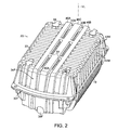
- FIG. 2 is another isometric view of the FIG. 1 tank, showing the bottom.
- FIG. 3 is a top view of the tank of FIG. 1 , with speckling to indicate a desired molded-in H-shape beam structure which lies nominally in the x-y plane of the top.
- FIG. 4 is an elevation view of the front end of the tank FIG. 1 .
- FIG. 5 is a transverse cross section view of a portion of the top of the tank FIG. 1 , showing a beam element which may be inserted and contained within a molded-in beam structure of the tank wall at the top.
- FIG. 6 is a transverse cross section view of a portion of the bottom of the tank, showing a supplemental beam which may be inserted and contained within a molded-in lengthwise beam structure of the tank wall at the bottom.
- FIG. 7 is a transverse cross section view of a portion of the top of the tank, showing a portion of the molded-in lengthwise beam structure.
- FIG. 8 is a fragmentary transverse cross section view of a portion of the bottom of the tank, showing a lengthwise molded-in beam structure, or rib, having a secondary rib, or sub-rib.
- FIG. 9 is an isometric view of a strut and baffle assembly for supporting the roof and sides of the tank and for dividing the length of the tank into compartments.
- FIG. 10 is a side elevation view of an end portion of a corrugated tank, showing a reinforcing rib in one of the peak corrugations.
- FIG. 11 is a vertical cross section through a portion of the tank shown in FIG. 10 .
- FIG. 12 is a bottom view of a corrugated tank having a multiplicity of parallel structural reinforcements running lengthwise.
- the tank described below has a multiplicity of features which are symmetrically disposed.
- suffixes for example, F or R (generally, front and rear) and A or B (generally, left and right in front view).
- a reference to a number without a suffix shall be understood to refer to any of the multiplicity of such elements have suffixes.
- a tank of the invention has certain shapes which are characterized as molded-in beam structures. By that is meant that if the particular portion were cut from the tank and used elsewhere it would have beam-like function. Also described are actual separate beams which may be nested within the molded-in beam structures for further strength.
- FIG. 1 is an isometric view of a molded plastic septic tank 20 with a superimposed x,y, z orthogonal axis system.
- FIG. 2 is similar and shows the bottom.
- FIG. 3 shows the top of the tank in plan view.
- FIG. 4 shows an end of the tank.
- FIG. 7 shows a cross section of the top of the tank.
- Tank 20 has a vertical cross section which is nominally rectangular; the tops and sides moderately bulge outward. A projection of the side or top of the tank into the vertical plane is rectangular.
- a tank has a cross section which approximates a circle, or where it has some other shape, it will be appreciated that the features of the present invention may be utilized. For instance, if the tank is circular in cross section, the transverse portions of the H shape molded-in beam, described below, will curve in the x direction.
- Tank 20 has two spaced vertical ports 24 , one at either end of the tank.
- An exemplary tank is about 124 inches long, about 66 inches wide and about 51 inches high and holds somewhat more than 1,000 gallons. It has two ports, each about 24 inch diameter.
- the ports 24 may comprise inserts or other strengthening features, not shown, to help resist distortion which would prevent good fit of hatch covers which close the ports off during use.
- Tank 20 comprises a wall 70 , which defines the interior volume of the tank.
- the wall 70 forms the bottom, sides and top.
- the wall 70 of the tank also defines the ends 34 , which are nominally dome shaped with corrugations.
- the ends 34 have buttresses 36 that provide flat vertical surfaces through which a hole may be cut for inflow or outflow of water to the tank, as indicated by the dashed circle.
- the ends have beam like flanges 32 to provide for bending strength in the horizontal plane. Flanges 32 also engage the soil and help resist any buoyant forces when that tank is empty, which would tend to lift the tank.
- the tank ends may have other constructions.
- Tank 20 has a plurality of support pads 62 on the opposing sides, for supporting the tank stably when it is set on its side, as for shipment. There is a plurality of lifting lugs 60 for attachment of lifting devices. There are also lifting holes in end flanges 32 .
- the four corners of the upper half of the tank comprise a series of stepped portions, or buttresses, 54 , which provide rigidity to the corners and therefore to the tank.
- the top 21 of tank 20 is characterized by a central portion CS, which comprises the portion which lies between the hatch ports 24 and which in a 1000 gallon tank is about one-third of the whole tank length.
- CS the circumferential surface of the tank is uninterrupted, as compared to being discontinuous where there are hatch ports.
- Tank 20 has a multiplicity of corrugations running transverse to the length axis L (which axis extends in the y-direction).
- the transverse corrugations comprised of peak corrugations 42 separated by, or alternating with, valley corrugations 44 .
- the transverse corrugations are named in distinction to the lengthwise corrugations, which as described below which have the character of providing a molded-in lengthwise beam structure.
- the transverse corrugations 42 , 44 run generally horizontally, except to the extent they may be interrupted by lengthwise beam structures or ports.
- the transverse corrugations 42 , 44 which run across the top and down the sides of the tank do not connect with the like corrugations which run across the bottom and up the sides of the tank, since they are separated by panel 30 . See FIG. 1 .
- the portion 30 can be conceived as presenting a lengthwise band which interconnects the tops of the peak corrugations 42 .
- the tank top and bottom have additional features which provide strength to the tank, greater than the transverse corrugations.
- the features both resist bending in the z plane, i.e., along the length axis L, and resist compression or accordioning of the tank, as under a vacuum test.
- the lengthwise corrugations may be continuous or discontinuous along the length of the tank, as described below. Those in the top will be first described.
- corrugation 22 runs lengthwise between two spaced apart transverse corrugations 25 R and 25 F which are respectively in close proximity to the ports 24 R and 24 F.
- Lengthwise valleys 52 A, 52 B lie on the left and right sides of lengthwise corrugation 22 .
- the structures 22 , 25 are pictured with speckling to highlight the H-shape of the combination.
- there are no transverse corrugations 25 and the corrugation 22 runs between the structure of the ports 24 .
- the transverse corrugations 25 which are simply particular peak corrugations 44 , run down the opposing sides of the tank. In the generality of the invention, they may only run partially or fully across the top to proximity of the left and right top edges.
- FIG. 1 and FIG. 3 show how transverse corrugations 25 are connected to the ring-like structure of ports 24 by means of a plurality of connectors 26 R and 26 F.
- Connectors 26 can be conceived as presenting an E-shape structure combination with the structure of ports 24 . See FIG. 3 .
- Connectors 26 span the valleys 42 providing better cooperation between the H-shape beam structure and the ports, and with the transverse peak corrugations 68 , 42 which connect to the structure of the ports 24 .
- there are two spaced apart lengthwise corrugations 22 instead of the one pictured.
- connectors 26 are instead solid; or there are no connectors 26 .
- the corrugation(s) 22 add strength to the top, in particular for resisting bending of the top in the continuous section CS which lies between the ports.
- the lengthwise corrugations 22 provide resistance against accordion-ing, and in such respect they cooperate with the ports 24 and the upper portions of the ends 34 , including buttresses 46 .
- optional internal bracing may be used to further enhance the strength of the top.
- the tank bottom 23 has transverse peak corrugations 42 M and valley corrugations 44 M, similar to those described in connection with the top. They run up the sides of the tank as previously mentioned.
- the bottom 23 of the tank also has a lengthwise strengthening structure, as shown in FIGS. 2 and 6 .
- the wall 70 at the bottom 23 of the tank has three parallel lengthwise peak corrugations 46 C, 46 A and 46 B; the latter two symmetrically spaced with respect to the vertical centerplane of the tank, which plane is indicated in the Figures by line VL. (Of course, when viewed from inside the tank, these same features appear as lengthwise cavities 46 as is seen in the partial vertical cross section of FIG.
- the lengthwise corrugations are also referred to here as molded-in beams. They are analogous in strengthening function to C-section beams, also called channels when free-standing, were such to be attached to the bottom of the tank.
- the tank bottom 23 also comprises four support pads 66 which are suited for supporting the tank bottom on a flat surface prior in storage or prior to installation.
- the lengthwise corrugations 46 are spaced apart from each other by discontinuous valleys 40 A, 40 B (which valleys appear as raised features inside the tank).
- Each valley may 40 have a sub-valley or rib, like sub-valley 48 T, shown in FIG. 8 on valley 40 T of alternative design wall bottom 23 T. See also the following description about FIG. 10 and FIG. 11 .
- the rib 48 T projects in the opposite direction from the floor of the valley 48 T, i.e., it projects outwardly from the chamber interior, compared to inwardly as in FIG. 8 .
- the corrugations 46 A, 46 B, 46 C preferably run lengthwise to the extent they continue around the corners at the ends of the tank bottom and run up the end walls 34 of the tank, as is readily visible in FIG. 2 . Alternately, they may run only to the bottom end corners of the tank.
- FIG. 10 shows a portion of the bottom end of a tank 20 C having a port 26 C.
- the tank has transverse peak corrugations 42 and valley corrugations 44 .
- One or more peak corrugations have a reinforcing rib 76 that runs along the corrugation surface.
- the configuration of the rib 76 is shown more particularly in FIG. 11 which is a cross section through the corrugation 42 .
- FIG. 11 shows how the rib is shaped. Rib 76 preferably tapers to a lesser depth at each end of the rib, as illustrated. Alternately, the rib may not taper but may be more abruptly shaped at the rib ends. Similar kinds of ribs may be placed in the valley corrugations and in peak corrugations at the ends of the tank.
- the transverse corrugations 42 M of the bottom 23 connect with the lengthwise corrugations 46 A, 46 B.
- the ends of the transverse corrugations may be spaced apart from the lengthwise corrugations, similar to the way in which the top corrugations 42 are spaced apart by lengthwise valleys 52 from lengthwise top corrugation 22 .
- the lengthwise beam structure corrugations 46 A, 46 B, 46 C on the bottom are interconnected by bridges 64 , as shown in FIG. 2 .
- the bridges are configured like transverse corrugations. Alternatively, the bridges may be omitted.
- FIG. 13 shows the bottom of tank 20 D which is longer and of greater capacity than tank 20 ; for example the tank can contain 1500 gallons.
- Tank 20 D has four molded in lengthwise beam structure corrugations 46 D which are spaced apart equally by intermittent valleys 40 D.
- the parallel beam structures 46 D are interconnected by bridges 64 D.
- FIG. 13 illustrates that when certain bridges, for example bridges 64 E, are aligned in the same vertical z-x plane (plane R in FIG. 13 ) with transverse bottom corrugations 44 D, there is formed a continuous interior channel. This channel is useful for receiving the edges of a baffle which is described below.
- a tank may optionally be further strengthened with supplemental beam members.
- a beam, 72 , 74 which is fabricated separately from the tank, is inserted into the concavity of a lengthwise corrugations or molded-in beam.
- Exemplary beams 72 , 74 are rectangular cross section hollow beams fabricated by pultrusion using iosphthalic polyster resin with long strand fiberglass reinforcement.
- Beams 72 , 74 may be used separately or in combination. Beams 72 , 74 may put in place, as indicated by the arrows in the Figures, after the tank is fabricated. They may be held in place by vertical struts 74 which are described below. Alternately, beams attached to the wall of the tank by fasteners or other mechanical means, or by adhesives or welding as the nature of the beam material may permit. Alternately, beams may be placed within the mold when the tank is molded, to thus become captured in the structure of the tank wall during the molding process. Beam cross sections other than rectangular may be used. Separately formed beams may also be placed within the transverse corrugations which comprise the H shape structure on the top.
- FIG. 9 shows a combination of vertical struts 74 and horizontal strut 82 which strengthen the tank against vertical and horizontal forces.
- the struts which may be constructed of the same kind of material as mentioned for the beams 72 , 74 , may be used with or without the presence of a baffle.
- the struts are positioned at a desired location within the length of the tank 20 , a portion of which is shown in phantom in FIG. 9 .
- the vertical struts will ordinarily be positioned to underlie the central circumferentially continuous body portion CS which lies between the access ports.
- the struts may lie in the vertical plane containing the transverse corrugation 25 F, which plane is approximately one-third of the distance along the length of the tank.
- the two spaced apart vertical struts 74 support the top of the tank against overlying loads.
- the horizontal strut 82 supports the sides of the tank against inward movement.
- only one vertical strut may be used.
- more than two vertical struts and more than one horizontal strut may be used.
- the struts may be fastened to one another or to the tank by means of mechanical fasteners.
- struts may be positioned at spaced apart locations between the access ports.
- struts may be located at each of the transverse planes P, Q, R illustrated in FIG. 13 .
- the top and bottom ends of the vertical struts may engage horizontally running angle beams 76 , 78 , as shown in FIG. 9 , so that any strut-load is not concentrated on the wall.
- the vertical struts may engage lengthwise beams, described above, which are within the tank.
- local pads or reinforcement may be used, or the struts may directly engage the wall of the tank without any intervening member, if concentration of load on the wall is not a concern.
- the struts also enable the positioning of a plastic sheet baffle 80 which has a through-hole 72 for liquid flow.
- baffles are familiar for dividing an upstream part of the tank from a downstream part.
- the vertical struts are on the downstream side of the baffle to provide support to the center part the baffle, and the baffle is sandwiched between those vertical struts and the horizontal strut 82 and fastened to them.
- the baffle has a peripheral edge dimension that engages the interior surface of peak corrugations 42 .
- the bottom of the baffle (and the angle beam 76 fit within the confines of the bridges 64 of tank 20 and the confines of the peak corrugations at the bottom and sides which are aligned with the bridges.
- the tank is made of solid polyethylene, polypropylene or other polyolefin.
- the wall 70 has three polyethylene layers, the center of which is comprised of closed cell polyethylene foam, for example, foamed polyethylene having a density of 10 lb. per cu. ft., alternately 20 lb. per cu. ft.
- the layers which are integrally connected, since they are melt-fused to each other during a rotational molding process described below.
- the layers cooperate to provide a wall that has particularly favorable properties insofar as utilization of material, flexural modulus, and impact strength are concerned.
- the outer layer may be comprised of two solid sub-layers. There may be fewer and more than three layers.
- the tank composite wall is comprised of a solid outer layer, a foam middle layer having a density less than about 55 percent of the outer layer, and a solid inner layer which is thinner than the outer layer.
- a typical outer layer is 0.15 inch thick
- a middle layer is 0.5 inch thick
- the inner layer is 0.05 inch thick.
- a hollow aluminum mold is heated and rotated about three orthogonal axes simultaneously, to melt and distribute about the mold inner surface plastic granular material which is placed within the mold.
- the mold is then cooled, split open, and the hollow molded article is removed.
- An embodiment of tank in the invention has ribbing or corrugations for strength.
- the tanks are preferably made of high density or low density polyethylene (HDPE, LDPE), alternately of polypropylene (PP), another polyolefin, or another thermoplastic.
- HDPE high density or low density polyethylene
- LDPE low density polyethylene
- PP polypropylene
- another polyolefin another thermoplastic.
- the shortened term “plastic” has been used herein to refer to thermoplastic.
- the tank of the invention can be made using the LeonardoTM rotational molding system of Persico S.p.A, a manufacturer in Nembro, Italy.
- the Leonardo system comprises automated equipment and is subject to various published patent applications.
- heating and cooling of the mold is achieved by channeling hot or cool liquids through or around the molds which are shaped to receive plastic internally and thereby form the part.
- the system is good at achieving selective temperatures throughout the mold, and obtaining good distribution of plastic within the mold, good wall thickness control, and high production rates.
- tank While a particular embodiment of tank is described here, other septic tanks within the scope of invention may be shorter or longer, and wider and taller than the exemplary tank; they may have different cross sectional shapes. For instance the cross section may be nominally trapezoid or nominally round. Also, the ports may have other shapes than round, and the tanks may also be made of other non-metal materials than have been mentioned.
Abstract
Description
Claims (11)
Priority Applications (1)
| Application Number | Priority Date | Filing Date | Title |
|---|---|---|---|
| US12/455,782 US8070005B1 (en) | 2008-06-05 | 2009-06-05 | Corrugated septic tank with strengthening features |
Applications Claiming Priority (2)
| Application Number | Priority Date | Filing Date | Title |
|---|---|---|---|
| US13099808P | 2008-06-05 | 2008-06-05 | |
| US12/455,782 US8070005B1 (en) | 2008-06-05 | 2009-06-05 | Corrugated septic tank with strengthening features |
Publications (1)
| Publication Number | Publication Date |
|---|---|
| US8070005B1 true US8070005B1 (en) | 2011-12-06 |
Family
ID=45034308
Family Applications (1)
| Application Number | Title | Priority Date | Filing Date |
|---|---|---|---|
| US12/455,782 Active - Reinstated 2029-09-01 US8070005B1 (en) | 2008-06-05 | 2009-06-05 | Corrugated septic tank with strengthening features |
Country Status (1)
| Country | Link |
|---|---|
| US (1) | US8070005B1 (en) |
Cited By (13)
| Publication number | Priority date | Publication date | Assignee | Title |
|---|---|---|---|---|
| US20120148777A1 (en) * | 2009-08-21 | 2012-06-14 | Basell Polyolefine Gmbh | Polyethylene for Rotomoulding |
| US20120149834A1 (en) * | 2009-08-21 | 2012-06-14 | Basell Polyolefine Gmbh | Polyethylene for Rotomoulding |
| US20130048645A1 (en) * | 2011-08-24 | 2013-02-28 | Kabushiki Kaisha Kobe Seiko Sho (Kobe Steel Ltd.) | Pressure vessel |
| CN103359901A (en) * | 2013-08-04 | 2013-10-23 | 宁夏大林科技有限公司 | Multipurpose cement septic tank |
| US8740005B1 (en) * | 2011-03-04 | 2014-06-03 | Infiltrator Systems, Inc. | Plastic tank having a clamped joint |
| US8789714B1 (en) | 2010-02-25 | 2014-07-29 | Infiltrator Systems Inc | Septic tank having deformation-resisting top access flange |
| US8857641B1 (en) * | 2011-03-04 | 2014-10-14 | Infiltrator Systems Inc | Manipulating and restraining a two piece septic tank |
| US20140326732A1 (en) * | 2011-09-21 | 2014-11-06 | Kautex Textron Gmbh & Co. Kg | Operating fluid tank for a motor vehicle |
| US9016979B1 (en) * | 2012-09-12 | 2015-04-28 | Infiltrator Systems, Inc. | Plastic stormwater chamber made from separately molded half chambers |
| JP2016175047A (en) * | 2015-03-20 | 2016-10-06 | フジクリーン工業株式会社 | Water treatment equipment |
| US9464451B1 (en) | 2015-08-28 | 2016-10-11 | Jack Skaw | Holding tanks, systems and methods |
| US20220356007A1 (en) * | 2021-05-06 | 2022-11-10 | Ovivo Inc. | Seal for Cover on Wastewater Treatment Tank |
| US11795679B2 (en) | 2021-07-19 | 2023-10-24 | Prinsco, Inc. | Asymmetric leaching chamber for onsite wastewater management system |
Citations (20)
| Publication number | Priority date | Publication date | Assignee | Title |
|---|---|---|---|---|
| US3383004A (en) * | 1965-08-17 | 1968-05-14 | Preload Co Inc | Plastic storage tank |
| US4143193A (en) | 1976-09-08 | 1979-03-06 | Phillips Petroleum Company | Molded container |
| US4359167A (en) | 1979-02-14 | 1982-11-16 | Hancor, Inc. | Subterranean plastic tank |
| US5220823A (en) | 1989-12-01 | 1993-06-22 | Xerxes Corporation | Double walled underground storage tank |
| US5321873A (en) | 1992-02-28 | 1994-06-21 | Goria Pierre A | Burial container |
| US5406759A (en) | 1993-08-04 | 1995-04-18 | W. R. Grace & Co.-Conn. | Method for protecting subgrade vertical wall from stone impacts in backfill operation and laminate for accomplishing the same |
| US5470515A (en) | 1991-06-05 | 1995-11-28 | Bayer Aktiengesellschaft | Rotational molding process for insulating pipes |
| US6170201B1 (en) | 1996-09-10 | 2001-01-09 | George E. Mason | Insulated burial vault |
| US6261490B1 (en) | 1998-09-15 | 2001-07-17 | Rotec Chemicals Limited | Rotational moulding |
| US6282763B1 (en) | 1999-09-20 | 2001-09-04 | Pierre A. Goria | Burial container and methods of making |
| US20010019026A1 (en) | 2000-03-02 | 2001-09-06 | Robin Berg | Residential septic tank |
| GB2369596A (en) | 2000-12-01 | 2002-06-05 | John Edward Barker | Process for manufacturing multi-walled vessels |
| US20020153380A1 (en) | 2001-04-20 | 2002-10-24 | Rochester Rotational Molding, Inc. | Apparatus and method for manufacturing a tank |
| US6698610B2 (en) | 1998-01-28 | 2004-03-02 | Robin Berg | Triple walled underground storage tank |
| USD498815S1 (en) * | 2003-09-12 | 2004-11-23 | Greer Tank, Inc. | Storage tank |
| US6852788B2 (en) | 2001-12-05 | 2005-02-08 | Michael J. Stevenson | Reinforcement composition for rotational molding |
| EP1557251A1 (en) | 2003-12-31 | 2005-07-27 | zweva Rotomoulding N.V. | Method for the production of a double-walled container by rotational moulding |
| EP1649997A1 (en) | 2004-10-22 | 2006-04-26 | Persico S.p.A. | Device and mold for rotational molding of plasic materials |
| US7144506B2 (en) | 2004-02-18 | 2006-12-05 | Fralo Plastech Mfg., Llc | Blow molded septic tank and method of manufacture |
| US7178686B2 (en) | 2002-01-23 | 2007-02-20 | Snyder Industries | Rotationally molded subterranean tank with riser |
-
2009
- 2009-06-05 US US12/455,782 patent/US8070005B1/en active Active - Reinstated
Patent Citations (20)
| Publication number | Priority date | Publication date | Assignee | Title |
|---|---|---|---|---|
| US3383004A (en) * | 1965-08-17 | 1968-05-14 | Preload Co Inc | Plastic storage tank |
| US4143193A (en) | 1976-09-08 | 1979-03-06 | Phillips Petroleum Company | Molded container |
| US4359167A (en) | 1979-02-14 | 1982-11-16 | Hancor, Inc. | Subterranean plastic tank |
| US5220823A (en) | 1989-12-01 | 1993-06-22 | Xerxes Corporation | Double walled underground storage tank |
| US5470515A (en) | 1991-06-05 | 1995-11-28 | Bayer Aktiengesellschaft | Rotational molding process for insulating pipes |
| US5321873A (en) | 1992-02-28 | 1994-06-21 | Goria Pierre A | Burial container |
| US5406759A (en) | 1993-08-04 | 1995-04-18 | W. R. Grace & Co.-Conn. | Method for protecting subgrade vertical wall from stone impacts in backfill operation and laminate for accomplishing the same |
| US6170201B1 (en) | 1996-09-10 | 2001-01-09 | George E. Mason | Insulated burial vault |
| US6698610B2 (en) | 1998-01-28 | 2004-03-02 | Robin Berg | Triple walled underground storage tank |
| US6261490B1 (en) | 1998-09-15 | 2001-07-17 | Rotec Chemicals Limited | Rotational moulding |
| US6282763B1 (en) | 1999-09-20 | 2001-09-04 | Pierre A. Goria | Burial container and methods of making |
| US20010019026A1 (en) | 2000-03-02 | 2001-09-06 | Robin Berg | Residential septic tank |
| GB2369596A (en) | 2000-12-01 | 2002-06-05 | John Edward Barker | Process for manufacturing multi-walled vessels |
| US20020153380A1 (en) | 2001-04-20 | 2002-10-24 | Rochester Rotational Molding, Inc. | Apparatus and method for manufacturing a tank |
| US6852788B2 (en) | 2001-12-05 | 2005-02-08 | Michael J. Stevenson | Reinforcement composition for rotational molding |
| US7178686B2 (en) | 2002-01-23 | 2007-02-20 | Snyder Industries | Rotationally molded subterranean tank with riser |
| USD498815S1 (en) * | 2003-09-12 | 2004-11-23 | Greer Tank, Inc. | Storage tank |
| EP1557251A1 (en) | 2003-12-31 | 2005-07-27 | zweva Rotomoulding N.V. | Method for the production of a double-walled container by rotational moulding |
| US7144506B2 (en) | 2004-02-18 | 2006-12-05 | Fralo Plastech Mfg., Llc | Blow molded septic tank and method of manufacture |
| EP1649997A1 (en) | 2004-10-22 | 2006-04-26 | Persico S.p.A. | Device and mold for rotational molding of plasic materials |
Non-Patent Citations (9)
| Title |
|---|
| Antosiewcz, F. "Plastic Vaults Help Lighten Burial Burden" Plastic News (Aug. 13, 2007) 2 pg. |
| Bay Systems, "Structurial Foam Rim" www.rimmolding.com (2004). 2 pg. |
| Nassar Delphin Group "NDG Compact Sewage Treatment Plants" www.nassar-delphin-group.com (Undated), p. 1, 2, 7, 31, 34, 45, 47. |
| Nugent, Paul "Rotational Molding: A Practical Guide", www.paulnugent.com (2001) p. 119-124; 333-344; 465-471; 575-589. |
| Premier Plastics Inc "Low Profile Supertank(TM) Septic Tank" www.premierplastics.com (2007) 2 pg. |
| Premier Plastics Inc "Low Profile Supertank™ Septic Tank" www.premierplastics.com (2007) 2 pg. |
| Roth Global Plastics Inc. "Plastic Septic Tanks Tanks" www.fnalo.net (2007) 1 pg. |
| Rotonics Manufacturing Inc, Cistern and Septic Tanks, www.rotonics.com(2003) 2 pg. |
| Rotonics Manufacturing Inc., "Septic Tanks" www.rotonics.com (2005) 2 pg. |
Cited By (18)
| Publication number | Priority date | Publication date | Assignee | Title |
|---|---|---|---|---|
| US8802803B2 (en) * | 2009-08-21 | 2014-08-12 | Basell Polyolefine Gmbh | Polyethylene for rotomoulding |
| US20120148777A1 (en) * | 2009-08-21 | 2012-06-14 | Basell Polyolefine Gmbh | Polyethylene for Rotomoulding |
| US8716423B2 (en) * | 2009-08-21 | 2014-05-06 | Basell Polyolefine Gmbh | Polyethylene for rotomoulding |
| US20120149834A1 (en) * | 2009-08-21 | 2012-06-14 | Basell Polyolefine Gmbh | Polyethylene for Rotomoulding |
| US8789714B1 (en) | 2010-02-25 | 2014-07-29 | Infiltrator Systems Inc | Septic tank having deformation-resisting top access flange |
| US8857641B1 (en) * | 2011-03-04 | 2014-10-14 | Infiltrator Systems Inc | Manipulating and restraining a two piece septic tank |
| US8740005B1 (en) * | 2011-03-04 | 2014-06-03 | Infiltrator Systems, Inc. | Plastic tank having a clamped joint |
| US20130048645A1 (en) * | 2011-08-24 | 2013-02-28 | Kabushiki Kaisha Kobe Seiko Sho (Kobe Steel Ltd.) | Pressure vessel |
| US8740008B2 (en) * | 2011-08-24 | 2014-06-03 | Kobe Steel, Ltd. | Pressure vessel |
| US20140326732A1 (en) * | 2011-09-21 | 2014-11-06 | Kautex Textron Gmbh & Co. Kg | Operating fluid tank for a motor vehicle |
| US9016979B1 (en) * | 2012-09-12 | 2015-04-28 | Infiltrator Systems, Inc. | Plastic stormwater chamber made from separately molded half chambers |
| CN103359901A (en) * | 2013-08-04 | 2013-10-23 | 宁夏大林科技有限公司 | Multipurpose cement septic tank |
| CN103359901B (en) * | 2013-08-04 | 2014-12-31 | 宁夏大林科技有限公司 | Multipurpose cement septic tank |
| JP2016175047A (en) * | 2015-03-20 | 2016-10-06 | フジクリーン工業株式会社 | Water treatment equipment |
| US9464451B1 (en) | 2015-08-28 | 2016-10-11 | Jack Skaw | Holding tanks, systems and methods |
| US11866251B2 (en) * | 2021-05-06 | 2024-01-09 | Ovivo Inc. | Seal for cover on wastewater treatment tank |
| US20220356007A1 (en) * | 2021-05-06 | 2022-11-10 | Ovivo Inc. | Seal for Cover on Wastewater Treatment Tank |
| US11795679B2 (en) | 2021-07-19 | 2023-10-24 | Prinsco, Inc. | Asymmetric leaching chamber for onsite wastewater management system |
Similar Documents
| Publication | Publication Date | Title |
|---|---|---|
| US8070005B1 (en) | Corrugated septic tank with strengthening features | |
| US9885171B2 (en) | Corrugated stormwater chamber having sub-corrugations | |
| US11242677B2 (en) | Corrugated stormwater chamber having sub-corrugations | |
| CA2314819C (en) | Septic waste treatment system | |
| KR101215010B1 (en) | Sealed, thermally insulated tank with juxtaposed non-conducting elements | |
| US7491015B2 (en) | Outwardly dished end plate for stormwater chamber | |
| US8151999B1 (en) | Plastic septic tank having layered composite wall | |
| US9850648B1 (en) | Stormwater chamber with stackable reinforcing ribs | |
| CN203757362U (en) | Reinforcement plate for pressure container and liquefied gas storage and transportation tank comprising reinforcement plate | |
| EP2931631B1 (en) | Modular tanks, method for constructing a modular tank and kit for constructing a modular tank | |
| US20060096980A1 (en) | Toroidal tank | |
| EP2138393B1 (en) | Modular floating system and a method of its manufacture | |
| US20220205232A1 (en) | Corrugated stormwater chamber having sub-corrugations | |
| CN210215122U (en) | Partition board of container and buried container | |
| KR101909351B1 (en) | Fabricated type hollow body for hollow core slab | |
| JP2004161319A (en) | Carrying container | |
| KR102584469B1 (en) | Top openable cover float | |
| KR200351952Y1 (en) | water tank | |
| US10655316B1 (en) | Concrete galley water detention and release systems | |
| WO2007070029A1 (en) | Container sidewall and related methods | |
| JPH021237Y2 (en) | ||
| JPH09314159A (en) | Purifying tank | |
| JP2001097481A (en) | Partition having reinforcing rib and sewage treatment tank | |
| KR200381548Y1 (en) | The polyethylene profile pipe having the compartment type of multistage and duplication | |
| JPH0219427Y2 (en) |
Legal Events
| Date | Code | Title | Description |
|---|---|---|---|
| AS | Assignment |
Owner name: INFILTRATOR SYSTEMS, INC., CONNECTICUT Free format text: ASSIGNMENT OF ASSIGNORS INTEREST;ASSIGNORS:BURNES, BRIAN;KRUGER, KURT J.;SIGNING DATES FROM 20090810 TO 20090928;REEL/FRAME:023329/0558 |
|
| FEPP | Fee payment procedure |
Free format text: PAYOR NUMBER ASSIGNED (ORIGINAL EVENT CODE: ASPN); ENTITY STATUS OF PATENT OWNER: LARGE ENTITY |
|
| AS | Assignment |
Owner name: GENERAL ELECTRIC CAPITAL CORPORATION, ILLINOIS Free format text: SECURITY AGREEMENT;ASSIGNOR:INFILTRATOR SYSTEMS, INC.;REEL/FRAME:027046/0088 Effective date: 20111011 |
|
| STCF | Information on status: patent grant |
Free format text: PATENTED CASE |
|
| AS | Assignment |
Owner name: EZFLOW, L.P., CONNECTICUT Free format text: RELEASE BY SECURED PARTY;ASSIGNOR:GENERAL ELECTRIC CAPITAL CORPORATION;REEL/FRAME:035745/0534 Effective date: 20150528 Owner name: INFILTRATOR SYSTEMS, INC., CONNECTICUT Free format text: RELEASE BY SECURED PARTY;ASSIGNOR:GENERAL ELECTRIC CAPITAL CORPORATION;REEL/FRAME:035745/0534 Effective date: 20150528 Owner name: ISI POLYETHYLENE SOLUTIONS, LLC, CONNECTICUT Free format text: RELEASE BY SECURED PARTY;ASSIGNOR:GENERAL ELECTRIC CAPITAL CORPORATION;REEL/FRAME:035745/0534 Effective date: 20150528 |
|
| AS | Assignment |
Owner name: DEUTSCHE BANK AG NEW YORK BRANCH, NEW YORK Free format text: SECURITY INTEREST;ASSIGNORS:ISI POLYETHYLENE SOLUTIONS, LLC;EZFLOW, L.P.;INFILTRATOR WATER TECHNOLOGIES, LLC;REEL/FRAME:036044/0627 Effective date: 20150527 Owner name: DEUTSCHE BANK AG NEW YORK BRANCH, NEW YORK Free format text: SECURITY INTEREST;ASSIGNORS:ISI POLYETHYLENE SOLUTIONS, LLC;EZFLOW, L.P.;INFILTRATOR WATER TECHNOLOGIES, LLC;REEL/FRAME:036044/0562 Effective date: 20150527 |
|
| REMI | Maintenance fee reminder mailed | ||
| AS | Assignment |
Owner name: INFILTRATOR WATER TECHNOLOGIES, LLC, CONNECTICUT Free format text: MERGER AND CHANGE OF NAME;ASSIGNORS:INFILTRATOR SYSTEMS, INC;INFILTRATOR WATER TECHNOLOGIES, LLC;REEL/FRAME:036387/0540 Effective date: 20150527 Owner name: INFILTRATOR WATER TECHNOLOGIES, LLC, CONNECTICUT Free format text: MERGER AND CHANGE OF NAME;ASSIGNORS:INFILTRATOR SYSTEMS, INC;INFILTRATOR WATER TECHNOLOGIES, LLC;REEL/FRAME:036387/0435 Effective date: 20150527 |
|
| FPAY | Fee payment |
Year of fee payment: 4 |
|
| SULP | Surcharge for late payment | ||
| AS | Assignment |
Owner name: EZFLOW, L.P., CONNECTICUT Free format text: RELEASE BY SECURED PARTY;ASSIGNOR:DEUTSCHE BANK AG NEW YORK;REEL/FRAME:041777/0638 Effective date: 20170217 Owner name: INFILTRATOR WATER TECHNOLOGIES, LLC, CONNECTICUT Free format text: RELEASE BY SECURED PARTY;ASSIGNOR:DEUTSCHE BANK AG NEW YORK;REEL/FRAME:041777/0638 Effective date: 20170217 Owner name: ISI POLYETHYLENE SOLUTIONS, LLC, CONNECTICUT Free format text: RELEASE BY SECURED PARTY;ASSIGNOR:DEUTSCHE BANK AG NEW YORK;REEL/FRAME:041777/0638 Effective date: 20170217 |
|
| FEPP | Fee payment procedure |
Free format text: MAINTENANCE FEE REMINDER MAILED (ORIGINAL EVENT CODE: REM.); ENTITY STATUS OF PATENT OWNER: LARGE ENTITY |
|
| AS | Assignment |
Owner name: ISI POLYETHYLENE SOLUTIONS, LLC, CONNECTICUT Free format text: RELEASE OF SECURITY INTERESTS IN PATENTS (RELEASES RF 036044/0562);ASSIGNOR:DEUTSCHE BANK AG NEW YORK BRANCH, AS COLLATERAL AGENT;REEL/FRAME:049942/0332 Effective date: 20190731 Owner name: EZFLOW, L.P., CONNECTICUT Free format text: RELEASE OF SECURITY INTERESTS IN PATENTS (RELEASES RF 036044/0562);ASSIGNOR:DEUTSCHE BANK AG NEW YORK BRANCH, AS COLLATERAL AGENT;REEL/FRAME:049942/0332 Effective date: 20190731 Owner name: INFILTRATOR WATER TECHNOLOGIES, LLC, CONNECTICUT Free format text: RELEASE OF SECURITY INTERESTS IN PATENTS (RELEASES RF 036044/0562);ASSIGNOR:DEUTSCHE BANK AG NEW YORK BRANCH, AS COLLATERAL AGENT;REEL/FRAME:049942/0332 Effective date: 20190731 |
|
| PRDP | Patent reinstated due to the acceptance of a late maintenance fee |
Effective date: 20191214 |
|
| AS | Assignment |
Owner name: BARCLAYS BANK PLC, AS ADMINISTRATIVE AGENT, NEW YO Free format text: SECURITY INTEREST;ASSIGNOR:INFILTRATOR WATER TECHNOLOGIES, LLC;REEL/FRAME:051287/0286 Effective date: 20191213 Owner name: BARCLAYS BANK PLC, AS ADMINISTRATIVE AGENT, NEW YORK Free format text: SECURITY INTEREST;ASSIGNOR:INFILTRATOR WATER TECHNOLOGIES, LLC;REEL/FRAME:051287/0286 Effective date: 20191213 |
|
| FEPP | Fee payment procedure |
Free format text: PETITION RELATED TO MAINTENANCE FEES GRANTED (ORIGINAL EVENT CODE: PMFG); ENTITY STATUS OF PATENT OWNER: LARGE ENTITY Free format text: SURCHARGE, PETITION TO ACCEPT PYMT AFTER EXP, UNINTENTIONAL (ORIGINAL EVENT CODE: M1558); ENTITY STATUS OF PATENT OWNER: LARGE ENTITY Free format text: PETITION RELATED TO MAINTENANCE FEES FILED (ORIGINAL EVENT CODE: PMFP); ENTITY STATUS OF PATENT OWNER: LARGE ENTITY |
|
| MAFP | Maintenance fee payment |
Free format text: PAYMENT OF MAINTENANCE FEE, 8TH YEAR, LARGE ENTITY (ORIGINAL EVENT CODE: M1552); ENTITY STATUS OF PATENT OWNER: LARGE ENTITY Year of fee payment: 8 |
|
| MAFP | Maintenance fee payment |
Free format text: PAYMENT OF MAINTENANCE FEE, 12TH YEAR, LARGE ENTITY (ORIGINAL EVENT CODE: M1553); ENTITY STATUS OF PATENT OWNER: LARGE ENTITY Year of fee payment: 12 |