US8072344B2 - Method and apparatus for visual silent alarm indicator - Google Patents
Method and apparatus for visual silent alarm indicator Download PDFInfo
- Publication number
- US8072344B2 US8072344B2 US12/702,657 US70265710A US8072344B2 US 8072344 B2 US8072344 B2 US 8072344B2 US 70265710 A US70265710 A US 70265710A US 8072344 B2 US8072344 B2 US 8072344B2
- Authority
- US
- United States
- Prior art keywords
- event
- buttons
- processor
- computer system
- coupled
- Prior art date
- Legal status (The legal status is an assumption and is not a legal conclusion. Google has not performed a legal analysis and makes no representation as to the accuracy of the status listed.)
- Expired - Fee Related
Links
Images


Classifications
-
- G—PHYSICS
- G06—COMPUTING; CALCULATING OR COUNTING
- G06F—ELECTRIC DIGITAL DATA PROCESSING
- G06F1/00—Details not covered by groups G06F3/00 - G06F13/00 and G06F21/00
- G06F1/16—Constructional details or arrangements
- G06F1/1613—Constructional details or arrangements for portable computers
- G06F1/1633—Constructional details or arrangements of portable computers not specific to the type of enclosures covered by groups G06F1/1615 - G06F1/1626
- G06F1/1684—Constructional details or arrangements related to integrated I/O peripherals not covered by groups G06F1/1635 - G06F1/1675
-
- G—PHYSICS
- G06—COMPUTING; CALCULATING OR COUNTING
- G06F—ELECTRIC DIGITAL DATA PROCESSING
- G06F1/00—Details not covered by groups G06F3/00 - G06F13/00 and G06F21/00
- G06F1/16—Constructional details or arrangements
- G06F1/1613—Constructional details or arrangements for portable computers
- G06F1/1626—Constructional details or arrangements for portable computers with a single-body enclosure integrating a flat display, e.g. Personal Digital Assistants [PDAs]
-
- G—PHYSICS
- G06—COMPUTING; CALCULATING OR COUNTING
- G06F—ELECTRIC DIGITAL DATA PROCESSING
- G06F1/00—Details not covered by groups G06F3/00 - G06F13/00 and G06F21/00
- G06F1/16—Constructional details or arrangements
- G06F1/1613—Constructional details or arrangements for portable computers
- G06F1/1632—External expansion units, e.g. docking stations
Definitions
- the present invention relates to the field of portable computer systems such as personal digital assistants or palmtops. Specifically, the present invention relates to a method and apparatus for providing a silent visual indicator (e.g., an alarm) for portable computer systems.
- a silent visual indicator e.g., an alarm
- a palmtop computer system is a computer that is small enough to be held in the hand of a user and is thus “palm-sized.” As a result, palmtops are readily carried about in a briefcase or purse, and some palmtops are compact enough to fit into a person's pocket. By virtue of their size, palmtop computer systems are also lightweight and so are exceptionally portable and convenient.
- a palmtop Because of the portability and convenience of palmtops, it is becoming increasingly desirable to increase the range of applications and functions for which they can be used. It is advantageous to expand the capabilities of a palmtop so that it can provide many of the same, if not the same, services provided by a personal computer (e.g., a desktop or laptop computer system), particularly with regard to access to the World Wide Web as well as the ability to communicate with other palmtops and personal computers. As such, information currently available via the Internet over personal computers, such as on-line access to news and financial information, can also be provided via a palmtop. In addition, a palmtop can be used for electronic mail (“e-mail”) and multi-player gaming, and features such as voice recognition can also be added.
- e-mail electronic mail
- multi-player gaming features such as voice recognition can also be added.
- Palmtop computers are also used very frequently as personal calendars, containing a user's schedule of meetings, appointments, and other items of significance such as birthdays and anniversaries.
- the user can open (e.g., display) the calendar to check for upcoming events.
- palmtops are generally equipped with an alarm that provides an audible indication to a user of an imminent appointment.
- the audible alarm currently used in palmtops is problematic because it is not appropriate for all situations and cannot be used by the hearing impaired.
- the audible signal can be disruptive and impolite.
- the sound of multiple alarms is exceptionally disruptive.
- audible alarms cannot always be used to signal events other than appointments, etc. That is, there may be a number of conditions associated with the different functions and applications mentioned above for which a user may wish to receive an alert, but with an audible alarm the signals may be virtually continuous, especially in an environment where multiple palmtops are present. Thus, instead of being subjected to too much noise, or subjecting others nearby to the noise, a user may elect to not receive an audible alarm when he or she would really rather have one.
- an audible signal can also be problematic in a noisy environment. It may not be possible to hear an audible alarm over the surrounding noise, in this case rendering the alarm useless.
- a portable computer system or personal digital assistant is adapted to generate a visual signal in response to the occurrence of a programmed event.
- the portable computer system uses a light emitting diode to visually signal an alarm at a specified time.
- the visual signal is generated in lieu of an audible signal, thus providing to the user a silent alarm that does not disturb other people in proximity.
- the visual signal can be varied in order to indicate the type of event or condition associated with the alarm.
- the visual signal blinks at a particular rate depending on the type of event.
- the visual signal blinks a prescribed number of times or according to a particular pattern depending on the type of event.
- the visual signal uses different colors depending on the type of event. The visual signal can thus be used to signal a wide variety of different events, and in particular can do so in an unobtrusive manner.
- the visual signal is disposed such that it is visible when the portable computer system is viewed either from the front or on edge.
- one of the buttons of the portable computer system is made translucent or transparent, and the visual indicator is situated beneath the button. When activated, the visual signal can be seen through the button; therefore, the button performs its normal function and also serves to provide the visual signal.
- the on/off button is located on the top edge of the front surface and so it can be seen when the portable computer system is viewed from the front or on edge. The on/off button can be made translucent and the visual indicator installed underneath it, and thus the button can perform both its normal function as well as the visual indicator function.
- FIG. 1A is a block diagram of an exemplary network environment including a portable computer system in accordance with one embodiment of the present invention.
- FIG. 1B is a block diagram of a portable computer system connected to other computer systems and the Internet via a cradle device in accordance with one embodiment of the present invention.
- FIG. 1C is a perspective view of the cradle device for connecting the portable computer system to other systems via a communication interface in accordance with one embodiment of the present invention.
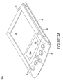
- FIG. 2A is a top side perspective view of a portable computer system with a visual indicator in accordance with one embodiment of the present invention.
- FIG. 2B is a bottom side perspective view of the portable computer system of FIG. 2A .
- FIG. 3 is a perspective view of a portable computer system with a visual indicator in accordance with another embodiment of the present invention.
- FIG. 4 is an exploded view of the components of a portable computer system in accordance with one embodiment of the present invention.
- FIG. 5 is a block diagram of one embodiment of a portable computer system with a visual indicator in accordance with the present invention.
- FIG. 6 is a flowchart of the steps in a process for providing a visual indication in accordance with one embodiment of the present invention.
- FIG. 1A is a block diagram of an exemplary network environment 50 including a portable computer system 100 in accordance with one embodiment of the present invention.
- Portable computer system 100 is also known as a palmtop or palm-sized computer system or as a personal digital assistant (PDA).
- PDA personal digital assistant
- portable computer system 100 has the ability to transmit and receive data and information over a wireless communication interface (e.g., a radio interface).
- the wireless communication interface is integrated into portable computer system 100 ; in another embodiment, the wireless communication interface is accomplished with a wireless modem attachment (not shown).
- base station 32 is both a transmitter and receiver base station, which can be implemented by coupling it into an existing public telephone network 34 .
- base station 32 enables portable computer system 100 to communicate with a proxy server computer system 36 , which is coupled by wire to the existing public telephone network 34 .
- proxy server computer system 36 is coupled to the Internet 52 , thereby enabling portable computer system 100 to communicate with the Internet 52 .
- Coupled with Internet 52 are multiple servers exemplified by server 30 . Residing on server 30 is a Web site 40 . When communicating with a Web site over Internet 52 , protocols such as CTP (Compact Transport Protocol) and CML (Compact Markup Language) can be used by portable computer system 100 in the present embodiment.
- CTP Cosmetic Transport Protocol
- CML Compact Markup Language
- proxy server 36 one of the functions of proxy server 36 is to perform operations over the Internet 52 on behalf of portable computer system 100 .
- proxy server 36 has a particular Internet address and acts as a proxy device for portable computer system 100 over the Internet 52 .
- a wireless connection may be made from portable computer system 100 directly to the Internet 52 .
- the data and information which are communicated between base station 32 and portable computer system 100 are the same type of information and data that can conventionally be transferred and received over a public telephone wire network system.
- a wireless communication interface is utilized to communicate data and information between portable computer system 100 and base station 32 .
- a wireless communication system in accordance with the present invention is the Mobitex wireless communication system.
- FIG. 1B illustrates another embodiment of a system 51 that can be used in conjunction with various embodiments of the present invention.
- System 51 comprises a host computer system 56 which can either be a desktop unit as shown, or, alternatively, can be a laptop system 58 .
- one or more host computer systems can be used within system 51 .
- Host computer systems 58 and 56 are shown connected to a communication bus 54 , which in one embodiment can be a serial communication bus, but could be of any of a number of well known designs, e.g., a parallel bus, Ethernet Local Area Network (LAN), etc.
- Bus 54 can provide communication with the Internet 52 using a number of well-known protocols. Coupled with Internet 52 are multiple servers exemplified by server 30 . Residing on server 30 is a Web site 40 .
- bus 54 is also coupled to a cradle 60 for receiving and initiating communication with portable computer system 100 of the present invention.
- Cradle 60 provides an electrical and mechanical communication interface between bus 54 (and anything coupled to bus 54 ) and the computer system 100 for two-way communications.
- portable computer system 100 may instead be coupled to host computer systems 56 and 58 via a wireless (radio) connection.
- Computer system 100 also contains a wireless infrared communication mechanism 64 for sending and receiving information from other devices (e.g., “beaming”).
- portable computer system 100 can be used in a network environment combining elements of networks 50 and 51 . That is, portable computer system 100 can include both a wireless infrared communication mechanism and a signal (e.g., radio) receiver/transmitter device.
- a wireless infrared communication mechanism e.g., Bluetooth
- a signal e.g., radio
- FIG. 1C is a perspective illustration of one embodiment of the cradle 60 for receiving the portable computer system 100 .
- Cradle 60 contains a mechanical and electrical interface 260 for interfacing with communication interface 108 ( FIG. 2B below) of computer system 100 when system 100 is slid into the cradle 60 in an upright position.
- button 270 can be pressed to initiate two-way communication (e.g., a communication session) between computer system 100 and other computer systems coupled to serial communication 265 .
- FIG. 2A is a perspective illustration of the top face 100 a of the housing of one embodiment of the portable computer system 100 of the present invention.
- the top face 100 a contains a display screen 105 surrounded by a bezel or cover.
- a removable stylus 80 is also shown.
- the display screen 105 is a touch screen able to register contact between the screen and the tip of the stylus 80 .
- the stylus 80 can be of any material to make contact with the screen 105 .
- the top face 100 a also contains one or more dedicated and/or programmable buttons 75 for selecting information and causing the computer system to implement functions.
- the on/off button 95 is also shown.
- FIG. 2A also illustrates a handwriting recognition pad or “digitizer” containing two regions 106 a and 106 b .
- Region 106 a is for the drawing of alphabetic characters therein (and not for numeric characters) for automatic recognition
- region 106 b is for the drawing of numeric characters therein (and not for alphabetic characters) for automatic recognition.
- the stylus 80 is used for stroking a character within one of the regions 106 a and 106 b .
- the stroke information is then fed to an internal processor for automatic character recognition. Once characters are recognized, they are typically displayed on the screen 105 for verification and/or modification.
- a visual indicator 92 is situated on the top face 100 a of portable computer system 100 .
- Visual indicator 92 comprises a light emitting diode (LED) or some other type of illuminating or visible element.
- visual indicator 92 is located within the housing of portable computer system 100 , and an optical pipe (or similar type of device) is used to convey the visible signal from visual indicator 92 to a position where the signal is visible to a user.
- Visual indicator 92 illuminates or blinks to provide a visual signal or visual alarm to a user. It is appreciated that visual indicator 92 may be situated in a position other than that shown (see FIG. 3 below, for example). It is further appreciated that, in another embodiment, visual indicator 92 may be incorporated into display device 105 , such that display device 105 flashes, blinks or otherwise provides a visual alert to a user.
- the visual signal can be used to alert a user to an upcoming meeting or appointment, or to alert the user that it is a particular time of day.
- a visual signal can also be used to alert a user of a particular condition associated with the functions and applications of portable computer system 100 (a “programmed event”). For example, a user may program portable computer system 100 to provide a visual signal as part of a single-player or multi-player game, when an e-mail is received, when battery power is low, when an input error is made, when information is beamed successfully (or not) from one portable device to another, etc. Additional information is provided in conjunction with FIG. 6 below.
- visual indicator 92 can vary the visual signal in order to indicate different types of conditions or programmed events.
- the visual signal can blink at a particular rate, blink a prescribed number of times, blink according to a particular pattern (e.g., a combination of longer and shorter blinks), or use different colors to signify the occurrence of different types of events or conditions. It is appreciated that the visual signal can be varied in other ways in accordance with the present invention.
- the present invention can be used to signal a large number of different events or conditions associated with the various applications and functions performed by portable computer system 100 , depending on user preferences.
- the present invention accomplishes these alert functions in an unobtrusive manner.
- portable computer system 100 also incorporates an audible indicator (not shown) that provides an audible indication or alarm to a user.
- audible indicator 92 provides a visual signal in lieu of an audible signal, although it is appreciated that any combination of a visual and audible signal can also be used in accordance with the present invention. It is further appreciated that visual indicator 92 may be enabled or disabled depending on the user's preferences.
- the present invention addresses the shortcomings of an audible signal. Namely, the visual signal generated by visual indicator 92 is not disruptive to others nearby, and it can be used by the hearing impaired. Furthermore, the visual signal makes it easier to identify which device is generating the alarm, and it is suitable for a noisy environment where an audible signal may not be heard.
- FIG. 2B illustrates the bottom side 100 b of the housing of one embodiment of the portable computer system that can be used in accordance with various embodiments of the present invention.
- An extendible antenna 85 is shown, and also a battery storage compartment door 90 is shown.
- a communication interface 180 is also shown.
- the communication interface 180 is a serial communication port, but could also alternatively be of any of a number of well-known communication standards and protocols, e.g., parallel, SCSI (small computer system interface), Firewire (IEEE 1394), Ethernet, etc.
- FIG. 3 is a perspective view of a portable computer system 100 with a visual indicator 92 in accordance with another embodiment of the present invention.
- visual indicator 92 is situated along the top edge of the top face 100 a , and as such can be seen by the user whether the user views portable computer system 100 from the front face or on edge.
- visual indicator 92 would still be visible and thus able to alert a user of a programmed event.
- on/off button 95 is transparent or translucent, and visual indicator 92 is situated beneath on/off button 95 or within the button itself. Thus, a visual signal can be seen through on/off button 95 .
- on/off button 95 is situated along the top edge of the top face 100 a , and as such the visual signal can be seen by the user whether the user views portable computer system 100 from the front face or on edge, as described above. Accordingly, on/off button 95 performs its normal function and also serves the additional function of emitting a visual signal generated by visual indicator 92 .
- Such a design is advantageous because it efficiently utilizes the limited space available given the compactness of portable computer system 100 . It is appreciated that, in other embodiments, other buttons or elements for performing a function or for causing a function to be performed, such as programmable buttons 75 , can be made transparent or translucent and combined with visual indicator 92 in a similar manner.
- FIG. 4 is an exploded view of the portable computer system 100 in accordance with one implementation.
- Computer system 100 has a housing comprised of a back cover 245 and a front cover 210 , which has an outline of region 106 and holes 75 a for receiving buttons 75 b .
- a flat panel display 105 (both liquid crystal display and touch screen) fits into front cover 210 . Any of a number of display technologies can be used, e.g., liquid crystal display (LCD), field emission display (FED), plasma, etc., for the flat panel display 105 .
- a battery 215 provides electrical power.
- a contrast adjustment (potentiometer) 220 is also shown, as well as an on/off button 95 .
- a flex circuit 230 is shown along with a printed circuit (PC) board 225 containing electronics and logic (e.g., memory, communication bus, processor, etc.) for implementing computer system functionality.
- the digitizer pad is also included in PC board 225 .
- a midframe 235 is shown along with stylus 80 .
- Position-adjustable antenna 85 is shown.
- Infrared communication mechanism 64 (e.g., an infrared emitter and detector device) is for sending and receiving information from other similarly equipped devices (see FIG. 1B ).
- a signal (e.g., radio) receiver/transmitter device 108 is also shown.
- the receiver/transmitter device 108 is coupled to the antenna 85 and also coupled to communicate with the PC board 225 .
- the Mobitex wireless communication system is used to provide two-way communication between computer system 100 and other networked computers and/or the Internet via a proxy server (see FIG. 1A ).
- Visual indicator 92 is for providing a visual signal to a user, as described above in conjunction with FIG. 2A .
- a port pin on a microprocessor drives a transistor which allows visual indicator 92 to blink on or off. It is appreciated that other mechanisms and devices can be used to provide and control a visual signal in accordance with the present invention.
- FIG. 5 illustrates circuitry of computer system 100 , some of which can be implemented on PC board 225 ( FIG. 4 ).
- Computer system 100 includes an address/data bus 110 for communicating information, a central processor 101 coupled with the bus for processing information and instructions, a volatile memory 102 (e.g., random access memory, RAM) coupled with the bus 110 for storing information and instructions for the central processor 101 and a non-volatile memory 103 (e.g., read only memory, ROM) coupled with the bus 110 for storing static information and instructions for the processor 101 .
- Computer system 100 also includes an optional data storage device 104 (e.g., memory stick) coupled with the bus 110 for storing information and instructions. Device 104 can be removable.
- computer system 100 also contains a display device 105 coupled to the bus 110 for displaying information to the computer user.
- PC board 225 can contain the processor 101 , the bus 110 , the ROM 103 and the RAM 102 .
- computer system 100 also includes a signal transmitter/receiver device 108 , which is coupled to bus 110 for providing a physical communication link between computer system 100 , and a network environment (e.g., network environments 50 and 51 of FIGS. 1A and 1B , respectively).
- signal transmitter/receiver device 108 enables central processor unit 101 to communicate wirelessly with other electronic systems coupled to the network.
- signal transmitter/receiver device 108 is coupled to antenna 85 ( FIG. 4 ) and provides the functionality to transmit and receive information over a wireless communication interface.
- the present embodiment of signal transmitter/receiver device 108 is well suited to be implemented in a wide variety of ways. For example, signal transmitter/receiver device 108 could be implemented as a modem.
- computer system 100 includes a communication circuit 109 coupled to bus 110 .
- Communication circuit 109 includes an optional digital signal processor (DSP) 120 for processing data to be transmitted or data that are received via signal transmitter/receiver device 108 .
- DSP digital signal processor
- processor 101 can perform some or all of the functions performed by DSP 120 .
- an optional alphanumeric input device 106 that in one implementation is a handwriting recognition pad (“digitizer”) having regions 106 a and 106 b ( FIG. 2 ), for instance.
- Alphanumeric input device 106 can communicate information and command selections to processor 101 .
- Computer system 100 also includes an optional cursor control or directing device (on-screen cursor control 107 ) coupled to bus 110 for communicating user input information and command selections to processor 101 .
- on-screen cursor control device 107 is a touch screen device incorporated with display device 105 .
- On-screen cursor control device 107 is capable of registering a position on display device 105 where the stylus makes contact.
- the display device 105 utilized with computer system 100 may be a liquid crystal display device, a cathode ray tube (CRT), a field emission display device (also called a flat panel CRT) or other display device suitable for generating graphic images and alphanumeric characters recognizable to the user.
- display device 105 is a flat panel display.
- visual indicator 92 is also coupled to processor 101 and to memory (e.g., RAM 102 or ROM 103 ) via bus 110 .
- visual indicator 92 functions to provide a visual signal or alarm to a user.
- Portable computer system 100 can be programmed to actuate visual indicator 92 at one or more times of day specified by a user.
- Visual indicator 92 can also be programmed to alert a user of one or more specified conditions or events associated with the various applications and functions performed by portable computer system 100 .
- audio indicator 94 for providing an audible signal or alarm to a user.
- visual indicator 92 may be used in combination with or in lieu of audio indicator 94 . It is appreciated that visual indicator 92 and/or audio indicator 94 may be enabled or disabled depending on the user's preferences.
- FIG. 6 is a flowchart of the steps in a process 600 for providing a visual indication in a portable computer system 100 ( FIG. 5 ) in accordance with one embodiment of the present invention.
- process 600 is implemented using visual indicator 92 in combination with processor 101 and RAM 102 or ROM 103 of FIG. 5 .
- dialog boxes and graphical user interfaces can be used by portable computer system 100 to receive the user input described below.
- step 610 of FIG. 6 depending on the user's preferences, the audible alarm (e.g., audio indicator 94 of FIG. 5 ) is disabled and visual indicator 92 is enabled. It is appreciated that, in accordance with the present invention, the visual signal can be used in lieu of the audible alarm, or that a combination of an audible alarm and a visual signal can be used.
- the audible alarm e.g., audio indicator 94 of FIG. 5
- the visual signal can be used in lieu of the audible alarm, or that a combination of an audible alarm and a visual signal can be used.
- a separate alarm can be set for any number of individual events or conditions, and each alarm can be signaled either visually or audibly or both.
- the user makes a selection with regard to a visual and/or audible alarm when programming into portable computer system 100 the events or conditions for which he or she wishes to be alerted (see step 620 ).
- portable computer system 100 is programmed with (e.g., receives) information regarding the particular events or conditions that will be signaled to the user. For example, a user selects the calendar function of portable computer system 100 and, in a known fashion, enters information with regard to an upcoming meeting. At this time, the user can also enable or disable the alarm function for this particular meeting. If enabled, the user can specify whether the alarm should be an audible alarm or a visual alarm or both.
- a user can identify other events or conditions for which an alert is to be provided, and can specify whether the alert should be visual and/or audible.
- a user may program portable computer system 100 to provide a visual signal as part of a single-player or multi-player game, when an e-mail is received, when battery power is low, when an input error is made, when information is beamed successfully (or not) from one portable device to another, etc.
- the user may specify certain types of visual signals depending on the type of event or condition. For example, the user may specify that visual indicator 92 should signal an upcoming meeting with a series of blinks according to one pattern, the arrival of an e-mail according to another pattern, and an input error by one relatively long signal.
- portable computer system 100 functions in its normal manner (step 635 ).
- a visual signal can be generated in accordance with the present invention to alert the user that the event has occurred. For example, for the case where the user wishes to be alerted to an upcoming meeting, the user can program portable computer system 100 to provide an alert a few minutes before the meeting.
- visual indicator 92 is directed to generate a visual signal.
- a specific type of visual signal can be used to indicate that the alert is for an upcoming meeting, as described above.
- the present invention provides an apparatus and method for generating a visual signal for a portable computer system 100 ( FIG. 5 ) that can be used instead of or in combination with an audible signal.
- the present invention provides an apparatus and method that maintains the functionality of an audible alarm, but addresses the shortcomings of an audible alarm.
- the visual signal generated by visual indicator 92 ( FIG. 5 ) is not disruptive to others nearby, and it can be used by the hearing impaired.
- the visual signal makes it easier to identify which device is generating the alarm, and it is suitable for a noisy environment where an audible signal may not be heard.
- the present invention also provides an apparatus and method that can provide alarms for any number of different conditions or events associated with the applications and functions performed by a portable computer system. Importantly, the present invention accomplishes these alert functions in an unobtrusive manner.
Abstract
Description
Claims (15)
Priority Applications (2)
| Application Number | Priority Date | Filing Date | Title |
|---|---|---|---|
| US12/702,657 US8072344B2 (en) | 2000-06-30 | 2010-02-09 | Method and apparatus for visual silent alarm indicator |
| US13/289,865 US8519862B2 (en) | 2000-06-30 | 2011-11-04 | Method and apparatus for visual silent alarm indicator |
Applications Claiming Priority (4)
| Application Number | Priority Date | Filing Date | Title |
|---|---|---|---|
| US09/607,894 US6831568B1 (en) | 2000-06-30 | 2000-06-30 | Method and apparatus for visual silent alarm indicator |
| US10/950,282 US7119706B1 (en) | 2000-06-30 | 2004-09-23 | Method and apparatus for visual silent alarm indicator |
| US11/544,280 US7659830B1 (en) | 2000-06-30 | 2006-10-06 | Method and apparatus for visual silent alarm indicator |
| US12/702,657 US8072344B2 (en) | 2000-06-30 | 2010-02-09 | Method and apparatus for visual silent alarm indicator |
Related Parent Applications (1)
| Application Number | Title | Priority Date | Filing Date |
|---|---|---|---|
| US11/544,280 Continuation US7659830B1 (en) | 2000-06-30 | 2006-10-06 | Method and apparatus for visual silent alarm indicator |
Related Child Applications (1)
| Application Number | Title | Priority Date | Filing Date |
|---|---|---|---|
| US13/289,865 Continuation US8519862B2 (en) | 2000-06-30 | 2011-11-04 | Method and apparatus for visual silent alarm indicator |
Publications (2)
| Publication Number | Publication Date |
|---|---|
| US20100141440A1 US20100141440A1 (en) | 2010-06-10 |
| US8072344B2 true US8072344B2 (en) | 2011-12-06 |
Family
ID=33490831
Family Applications (5)
| Application Number | Title | Priority Date | Filing Date |
|---|---|---|---|
| US09/607,894 Expired - Fee Related US6831568B1 (en) | 2000-06-30 | 2000-06-30 | Method and apparatus for visual silent alarm indicator |
| US10/950,282 Expired - Fee Related US7119706B1 (en) | 2000-06-30 | 2004-09-23 | Method and apparatus for visual silent alarm indicator |
| US11/544,280 Expired - Fee Related US7659830B1 (en) | 2000-06-30 | 2006-10-06 | Method and apparatus for visual silent alarm indicator |
| US12/702,657 Expired - Fee Related US8072344B2 (en) | 2000-06-30 | 2010-02-09 | Method and apparatus for visual silent alarm indicator |
| US13/289,865 Expired - Fee Related US8519862B2 (en) | 2000-06-30 | 2011-11-04 | Method and apparatus for visual silent alarm indicator |
Family Applications Before (3)
| Application Number | Title | Priority Date | Filing Date |
|---|---|---|---|
| US09/607,894 Expired - Fee Related US6831568B1 (en) | 2000-06-30 | 2000-06-30 | Method and apparatus for visual silent alarm indicator |
| US10/950,282 Expired - Fee Related US7119706B1 (en) | 2000-06-30 | 2004-09-23 | Method and apparatus for visual silent alarm indicator |
| US11/544,280 Expired - Fee Related US7659830B1 (en) | 2000-06-30 | 2006-10-06 | Method and apparatus for visual silent alarm indicator |
Family Applications After (1)
| Application Number | Title | Priority Date | Filing Date |
|---|---|---|---|
| US13/289,865 Expired - Fee Related US8519862B2 (en) | 2000-06-30 | 2011-11-04 | Method and apparatus for visual silent alarm indicator |
Country Status (1)
| Country | Link |
|---|---|
| US (5) | US6831568B1 (en) |
Families Citing this family (21)
| Publication number | Priority date | Publication date | Assignee | Title |
|---|---|---|---|---|
| US6831568B1 (en) | 2000-06-30 | 2004-12-14 | Palmone, Inc. | Method and apparatus for visual silent alarm indicator |
| US7319744B1 (en) * | 2001-01-31 | 2008-01-15 | Palmsource, Inc. | Unified messaging/call routing configuration using palmtop computer |
| US6621697B2 (en) | 2001-05-24 | 2003-09-16 | Palm, Inc. | Stylus visual indicator system |
| AUPR584801A0 (en) * | 2001-06-21 | 2001-07-12 | Kain, Olga Mrs | Memory jogger |
| US6720863B2 (en) * | 2001-08-16 | 2004-04-13 | Wildseed Ltd. | Mobile electronic communication device with lights to indicate received messages |
| JP2004234505A (en) * | 2003-01-31 | 2004-08-19 | Toshiba Corp | Information processing equipment and state notifying method |
| US7433714B2 (en) * | 2003-06-30 | 2008-10-07 | Microsoft Corporation | Alert mechanism interface |
| US20050068172A1 (en) * | 2003-09-29 | 2005-03-31 | King Deborah L. | Parental alert and child tracking device |
| JP4735935B2 (en) * | 2004-10-04 | 2011-07-27 | 横河電機株式会社 | Device display |
| US20060227756A1 (en) * | 2005-04-06 | 2006-10-12 | Viresh Rustagi | Method and system for securing media content in a multimedia processor |
| US7894848B2 (en) * | 2006-08-31 | 2011-02-22 | Research In Motion Limited | System and method for providing a standby mode in a handheld electronic device |
| US7573371B1 (en) | 2006-11-02 | 2009-08-11 | Tony Miller | Alarm system for dementia patients |
| US7656275B2 (en) * | 2006-12-22 | 2010-02-02 | Research In Motion Limited | System and method for controlling an alarm for an electronic device |
| US9300773B2 (en) * | 2008-05-01 | 2016-03-29 | Apple Inc. | Portable electronic device with moisture infiltration indication system |
| KR20110013606A (en) * | 2009-08-03 | 2011-02-10 | 엘지전자 주식회사 | Method for executing menu in mobile terminal and mobile terminal thereof |
| US8749349B2 (en) * | 2011-03-11 | 2014-06-10 | Nokia Corporation | Method apparatus and computer program |
| MA37972A1 (en) * | 2012-09-04 | 2016-01-29 | Net1 Ueps Technologies Inc | Financial Transactions Using a Variable Personal Identification Number (PIN) |
| US11354008B2 (en) * | 2016-08-10 | 2022-06-07 | Microsoft Technology Licensing, Llc | Visual notification |
| JP2019012906A (en) * | 2017-06-29 | 2019-01-24 | オムロン株式会社 | Electrical device |
| DE102017125440A1 (en) * | 2017-10-30 | 2019-05-02 | PAG Solutions GmbH | Joint for a kitchen monitor |
| US11762540B2 (en) | 2021-05-19 | 2023-09-19 | Caterpillar Inc. | Systems and methods for managing on-site machines by dynamic off-screen indicators |
Citations (14)
| Publication number | Priority date | Publication date | Assignee | Title |
|---|---|---|---|---|
| US5088056A (en) | 1985-02-19 | 1992-02-11 | Kenneth B. McIntosh | Medication clock |
| US5210532A (en) | 1991-09-03 | 1993-05-11 | Gerry Baby Products Company | Baby monitor receiver having indicator display and dual position clip |
| US5546078A (en) | 1990-03-29 | 1996-08-13 | Nec Corporation | Paging receiver capable of reporting the time of paging connection |
| US5570025A (en) | 1994-11-16 | 1996-10-29 | Lauritsen; Dan D. | Annunciator and battery supply measurement system for cellular telephones |
| US5760690A (en) | 1996-05-02 | 1998-06-02 | Digital Equipment Corporation | Portable computer with integrated alarm system |
| US5796575A (en) | 1992-12-21 | 1998-08-18 | Hewlett-Packard Company | Portable computer with hinged cover having a window |
| US5861815A (en) | 1997-01-24 | 1999-01-19 | Silicon Graphics, Inc. | Light bar and reflector assembly |
| US5877695A (en) | 1997-10-07 | 1999-03-02 | Ericsson, Inc. | Visual alarm for a communication module |
| US5946386A (en) | 1996-03-11 | 1999-08-31 | Xantel Corporation | Call management system with call control from user workstation computers |
| US5973612A (en) | 1996-09-19 | 1999-10-26 | Microsoft Corporation | Flexible object notification |
| US6144363A (en) | 1996-12-16 | 2000-11-07 | Video Road Digital Inc. | Message status display |
| US6268789B1 (en) | 1996-11-22 | 2001-07-31 | Voltaire Advanced Data Security Ltd. | Information security method and apparatus |
| US6310634B1 (en) | 1997-08-04 | 2001-10-30 | Starfish Software, Inc. | User interface methodology supporting light data entry for microprocessor device having limited user input |
| US6831568B1 (en) * | 2000-06-30 | 2004-12-14 | Palmone, Inc. | Method and apparatus for visual silent alarm indicator |
Family Cites Families (5)
| Publication number | Priority date | Publication date | Assignee | Title |
|---|---|---|---|---|
| US5096195A (en) * | 1988-08-04 | 1992-03-17 | Elbit Computers Ltd. | Electronic gaming apparatus |
| JPH09233171A (en) * | 1996-02-26 | 1997-09-05 | Sony Corp | Communication terminal equipment |
| US6209011B1 (en) * | 1997-05-08 | 2001-03-27 | Microsoft Corporation | Handheld computing device with external notification system |
| JPH11205432A (en) * | 1998-01-08 | 1999-07-30 | Matsushita Electric Ind Co Ltd | Portable terminal device |
| US6046574A (en) * | 1999-06-04 | 2000-04-04 | Sony Corporation | Battery dropout correction for battery monitoring in mobile unit |
-
2000
- 2000-06-30 US US09/607,894 patent/US6831568B1/en not_active Expired - Fee Related
-
2004
- 2004-09-23 US US10/950,282 patent/US7119706B1/en not_active Expired - Fee Related
-
2006
- 2006-10-06 US US11/544,280 patent/US7659830B1/en not_active Expired - Fee Related
-
2010
- 2010-02-09 US US12/702,657 patent/US8072344B2/en not_active Expired - Fee Related
-
2011
- 2011-11-04 US US13/289,865 patent/US8519862B2/en not_active Expired - Fee Related
Patent Citations (16)
| Publication number | Priority date | Publication date | Assignee | Title |
|---|---|---|---|---|
| US5088056A (en) | 1985-02-19 | 1992-02-11 | Kenneth B. McIntosh | Medication clock |
| US5546078A (en) | 1990-03-29 | 1996-08-13 | Nec Corporation | Paging receiver capable of reporting the time of paging connection |
| US5210532A (en) | 1991-09-03 | 1993-05-11 | Gerry Baby Products Company | Baby monitor receiver having indicator display and dual position clip |
| US5796575A (en) | 1992-12-21 | 1998-08-18 | Hewlett-Packard Company | Portable computer with hinged cover having a window |
| US5570025A (en) | 1994-11-16 | 1996-10-29 | Lauritsen; Dan D. | Annunciator and battery supply measurement system for cellular telephones |
| US5946386A (en) | 1996-03-11 | 1999-08-31 | Xantel Corporation | Call management system with call control from user workstation computers |
| US5760690A (en) | 1996-05-02 | 1998-06-02 | Digital Equipment Corporation | Portable computer with integrated alarm system |
| US5973612A (en) | 1996-09-19 | 1999-10-26 | Microsoft Corporation | Flexible object notification |
| US6268789B1 (en) | 1996-11-22 | 2001-07-31 | Voltaire Advanced Data Security Ltd. | Information security method and apparatus |
| US6144363A (en) | 1996-12-16 | 2000-11-07 | Video Road Digital Inc. | Message status display |
| US5861815A (en) | 1997-01-24 | 1999-01-19 | Silicon Graphics, Inc. | Light bar and reflector assembly |
| US6310634B1 (en) | 1997-08-04 | 2001-10-30 | Starfish Software, Inc. | User interface methodology supporting light data entry for microprocessor device having limited user input |
| US5877695A (en) | 1997-10-07 | 1999-03-02 | Ericsson, Inc. | Visual alarm for a communication module |
| US6831568B1 (en) * | 2000-06-30 | 2004-12-14 | Palmone, Inc. | Method and apparatus for visual silent alarm indicator |
| US7119706B1 (en) | 2000-06-30 | 2006-10-10 | Palm, Inc | Method and apparatus for visual silent alarm indicator |
| US7659830B1 (en) * | 2000-06-30 | 2010-02-09 | Palm, Inc. | Method and apparatus for visual silent alarm indicator |
Also Published As
| Publication number | Publication date |
|---|---|
| US20100141440A1 (en) | 2010-06-10 |
| US20120112921A1 (en) | 2012-05-10 |
| US6831568B1 (en) | 2004-12-14 |
| US7659830B1 (en) | 2010-02-09 |
| US7119706B1 (en) | 2006-10-10 |
| US8519862B2 (en) | 2013-08-27 |
Similar Documents
| Publication | Publication Date | Title |
|---|---|---|
| US8072344B2 (en) | Method and apparatus for visual silent alarm indicator | |
| US8031212B2 (en) | Reorienting display on portable computing device | |
| US6954356B1 (en) | Keyboard sled with rotating screen | |
| US6678535B1 (en) | Pervasive dock and router with communication protocol converter | |
| US7289772B1 (en) | Technique allowing a status bar user response on a portable device graphic user interface | |
| JP4527335B2 (en) | Accessory device including a mobile communication device having first and second user interfaces, a keypad for a mobile radio telephone, and a display unit | |
| US20080032673A1 (en) | Method and apparatus for selective and automatic two-way beaming of related information to and from personal information management systems | |
| US8001488B1 (en) | User interface dial with display | |
| US8280448B2 (en) | Haptic effect provisioning for a mobile communication terminal | |
| USRE43070E1 (en) | Identifying and locating lost or stolen personal digital assistant devices via a landline- or wireless-connected web server | |
| US7370289B1 (en) | Method and apparatus for notification on an electronic handheld device using an attention manager | |
| US6525997B1 (en) | Efficient use of display real estate in a wrist watch display | |
| JPH1039967A (en) | Storage device for individual for application and data transfer | |
| US20030156381A1 (en) | Portable terminal with foldable keyboard | |
| US6888534B1 (en) | Segmented keyboard for portable computer system | |
| EP1168769A2 (en) | Demand pull-multichannel asynchronous data and application synchronization for pervasive devices | |
| US6906701B1 (en) | Illuminatable buttons and method for indicating information using illuminatable buttons | |
| US20080112554A1 (en) | Unified messaging/call routing configuration using palmtop computer | |
| CN108629171A (en) | A kind of unread message processing method and terminal | |
| US20030038790A1 (en) | Information processing system, input/output apparatus, personal digital assistant, and display apparatus | |
| US6952601B2 (en) | Display for a portable terminal | |
| CN112825048B (en) | Message reminding method and device, electronic equipment and storage medium | |
| JPH11191027A (en) | Computer presentation system | |
| JP2001216088A (en) | Mouse for personal computer |
Legal Events
| Date | Code | Title | Description |
|---|---|---|---|
| STCF | Information on status: patent grant |
Free format text: PATENTED CASE |
|
| AS | Assignment |
Owner name: PALM, INC., CALIFORNIA Free format text: ASSIGNMENT OF ASSIGNORS INTEREST;ASSIGNOR:HEWLETT-PACKARD DEVELOPMENT COMPANY, L.P.;REEL/FRAME:030341/0459 Effective date: 20130430 |
|
| AS | Assignment |
Owner name: PALM, INC., CALIFORNIA Free format text: ASSIGNMENT OF ASSIGNORS INTEREST;ASSIGNOR:HEWLETT-PACKARD DEVELOPMENT COMPANY, L.P.;REEL/FRAME:031837/0544 Effective date: 20131218 Owner name: HEWLETT-PACKARD DEVELOPMENT COMPANY, L.P., TEXAS Free format text: ASSIGNMENT OF ASSIGNORS INTEREST;ASSIGNOR:PALM, INC.;REEL/FRAME:031837/0659 Effective date: 20131218 Owner name: HEWLETT-PACKARD DEVELOPMENT COMPANY, L.P., TEXAS Free format text: ASSIGNMENT OF ASSIGNORS INTEREST;ASSIGNOR:PALM, INC.;REEL/FRAME:031837/0239 Effective date: 20131218 |
|
| AS | Assignment |
Owner name: QUALCOMM INCORPORATED, CALIFORNIA Free format text: ASSIGNMENT OF ASSIGNORS INTEREST;ASSIGNORS:HEWLETT-PACKARD COMPANY;HEWLETT-PACKARD DEVELOPMENT COMPANY, L.P.;PALM, INC.;REEL/FRAME:032132/0001 Effective date: 20140123 |
|
| FPAY | Fee payment |
Year of fee payment: 4 |
|
| FEPP | Fee payment procedure |
Free format text: MAINTENANCE FEE REMINDER MAILED (ORIGINAL EVENT CODE: REM.); ENTITY STATUS OF PATENT OWNER: LARGE ENTITY |
|
| LAPS | Lapse for failure to pay maintenance fees |
Free format text: PATENT EXPIRED FOR FAILURE TO PAY MAINTENANCE FEES (ORIGINAL EVENT CODE: EXP.); ENTITY STATUS OF PATENT OWNER: LARGE ENTITY |
|
| STCH | Information on status: patent discontinuation |
Free format text: PATENT EXPIRED DUE TO NONPAYMENT OF MAINTENANCE FEES UNDER 37 CFR 1.362 |
|
| FP | Lapsed due to failure to pay maintenance fee |
Effective date: 20191206 |