US8072347B2 - Method and apparatus for locating faults in wired drill pipe - Google Patents
Method and apparatus for locating faults in wired drill pipe Download PDFInfo
- Publication number
- US8072347B2 US8072347B2 US11/648,139 US64813906A US8072347B2 US 8072347 B2 US8072347 B2 US 8072347B2 US 64813906 A US64813906 A US 64813906A US 8072347 B2 US8072347 B2 US 8072347B2
- Authority
- US
- United States
- Prior art keywords
- pipe
- string
- electrical
- detecting
- electromagnetic field
- Prior art date
- Legal status (The legal status is an assumption and is not a legal conclusion. Google has not performed a legal analysis and makes no representation as to the accuracy of the status listed.)
- Active, expires
Links
- 238000000034 method Methods 0.000 title claims abstract description 33
- 230000005672 electromagnetic field Effects 0.000 claims abstract description 27
- 239000004020 conductor Substances 0.000 claims abstract description 18
- 230000001939 inductive effect Effects 0.000 claims abstract description 16
- 238000005553 drilling Methods 0.000 claims description 35
- 238000012360 testing method Methods 0.000 description 11
- 238000005259 measurement Methods 0.000 description 10
- 230000015572 biosynthetic process Effects 0.000 description 8
- 238000005755 formation reaction Methods 0.000 description 8
- 239000012530 fluid Substances 0.000 description 7
- 238000007689 inspection Methods 0.000 description 5
- 230000008878 coupling Effects 0.000 description 3
- 238000010168 coupling process Methods 0.000 description 3
- 238000005859 coupling reaction Methods 0.000 description 3
- 230000008901 benefit Effects 0.000 description 2
- 238000011156 evaluation Methods 0.000 description 2
- 230000000704 physical effect Effects 0.000 description 2
- 238000012545 processing Methods 0.000 description 2
- 230000005855 radiation Effects 0.000 description 2
- 238000013459 approach Methods 0.000 description 1
- 238000004891 communication Methods 0.000 description 1
- 230000003750 conditioning effect Effects 0.000 description 1
- 238000013500 data storage Methods 0.000 description 1
- 230000007423 decrease Effects 0.000 description 1
- 230000003247 decreasing effect Effects 0.000 description 1
- 238000001514 detection method Methods 0.000 description 1
- 238000005516 engineering process Methods 0.000 description 1
- 239000011152 fibreglass Substances 0.000 description 1
- 239000000696 magnetic material Substances 0.000 description 1
- 238000004519 manufacturing process Methods 0.000 description 1
- 239000002184 metal Substances 0.000 description 1
- 238000012544 monitoring process Methods 0.000 description 1
- 230000010363 phase shift Effects 0.000 description 1
- 238000005086 pumping Methods 0.000 description 1
- 238000007789 sealing Methods 0.000 description 1
- 230000035939 shock Effects 0.000 description 1
- 238000006467 substitution reaction Methods 0.000 description 1
- 238000012546 transfer Methods 0.000 description 1
- 238000011179 visual inspection Methods 0.000 description 1
Images


Classifications
-
- E—FIXED CONSTRUCTIONS
- E21—EARTH DRILLING; MINING
- E21B—EARTH DRILLING, e.g. DEEP DRILLING; OBTAINING OIL, GAS, WATER, SOLUBLE OR MELTABLE MATERIALS OR A SLURRY OF MINERALS FROM WELLS
- E21B47/00—Survey of boreholes or wells
- E21B47/12—Means for transmitting measuring-signals or control signals from the well to the surface, or from the surface to the well, e.g. for logging while drilling
-
- G—PHYSICS
- G01—MEASURING; TESTING
- G01R—MEASURING ELECTRIC VARIABLES; MEASURING MAGNETIC VARIABLES
- G01R31/00—Arrangements for testing electric properties; Arrangements for locating electric faults; Arrangements for electrical testing characterised by what is being tested not provided for elsewhere
- G01R31/50—Testing of electric apparatus, lines, cables or components for short-circuits, continuity, leakage current or incorrect line connections
Definitions
- the invention relates generally to the field of signal telemetry for equipment used in drilling wellbores through the Earth. More particularly, the invention relates to methods and apparatus for locating faults in so-called “wired” drill pipe used for such telemetry.
- Devices are known in the art for making measurements of various drilling parameters and physical properties of Earth formations as a wellbore is drilled through such formations.
- the devices are known as measurement while drilling (“MWD”) for devices that measure various drilling parameters such as wellbore trajectory, stresses applied to the drill string and motion of the drill string.
- the devices are also known as logging while drilling (“LWD”) for devices that measure various physical properties of the formations, such as electrical resistivity, natural gamma radiation emission, acoustic velocity, bulk density and others.
- the various MWD and LWD devices are coupled near the bottom end of a “drill string,” which is an assembly of drill pipe segments and other drilling tools threadedly coupled end to end with a drill bit at the lowest end.
- the drill string is suspended in the wellbore so that a portion of its weight is transferred to the drill bit, and the drill bit is rotated to drill through the Earth formations.
- Sensors on the various MWD and LWD devices can make the respective measurements during drilling operations.
- Wellbore drilling operators generally find that MWD and LWD measurements are particularly valuable when obtained during the actual drilling of the wellbore. For example, resistivity and gamma radiation measurements obtained during drilling may be compared with similar measurements made from a nearby wellbore so as to determine which Earth formations are believed to be penetrated by the wellbore at any moment in time.
- MWD and LWD measurements may be communicated to the surface through telemetry between the bottom hole assembly and the surface.
- Mud pulse telemetry is generated by modulating the flow of the drilling fluid proximate the MWD or LWD devices in a manner to cause detectable changes in pressure and/or flow rate of the drilling fluid at the Earth's surface.
- the modulation is typically performed to represent binary digital words, using techniques such as Manchester code or phase shift keying. It is well known in the art that drilling fluid flow modulation is capable of transmitting at a rate of only a few bits per second.
- U.S. Pat. No. 4,126,848 issued to Denison discloses a drill string telemetry system, wherein an armored electrical cable (“wireline”) is used to transmit data from near the bottom of the wellbore to an intermediate position in the drill string, and a special drill string, having an insulated electrical conductor, is used to transmit the information from the intermediate position to the Earth's surface.
- wireline armored electrical cable
- U.S. Pat. No. 4,126,848 issued to Denison discloses a drill string telemetry system, wherein an armored electrical cable (“wireline”) is used to transmit data from near the bottom of the wellbore to an intermediate position in the drill string, and a special drill string, having an insulated electrical conductor, is used to transmit the information from the intermediate position to the Earth's surface.
- a special drill string having an insulated electrical conductor
- the system disclosed in the '880 patent is for transmitting data through a string of components disposed in a wellbore.
- the system includes first and second magnetically conductive, electrically insulating elements at both ends of each drill string component.
- Each element includes a first U-shaped trough with a bottom, first and second sides and an opening between the two sides. Electrically conducting coils are located in each trough. An electrical conductor connects the coils in each component.
- a time-varying current applied to a first coil in one component generates a time-varying magnetic field in the first magnetically conductive, electrically insulating element, which time-varying magnetic field is conducted to and thereby produces a time-varying magnetic field in the second magnetically conductive, electrically insulating element of a connected component, which magnetic field thereby generates a time-varying electrical current in the second coil in the connected component.
- a wired drill pipe telemetry system includes a surface computer; and a drill string telemetry link comprising a plurality of wired drill pipes each having a telemetry section, at least one of the plurality of wired drill pipes having a diagnostic module electrically coupling the telemetry section and wherein the diagnostic module includes a line interface adapted to interface with a wired drill pipe telemetry section; a transceiver adapted to communicate signals between the wired drill pipe telemetry section and the diagnostic module; and a controller operatively connected with the transceiver and adapted to control the transceiver.
- the '961 patent describes a number of issues that must be addressed for the successful implementation of a wired drill pipe (“WDP”) telemetry system.
- WDP wired drill pipe
- a 15,000 ft (5472 m) wellbore will typically have about 500 drill pipe segment if each of the drill pipe segments is about 30 ft (9.14 m) long.
- the sheer number of pipe to pipe connections in such a WDP drill string raises concerns of reliability for the system.
- a commercially acceptable drilling system is expected to have a mean time between failure (“MTBF)” of about 500 hours or more. If any one of the electrical connections in the WDP drill string fails, then the entire WDP telemetry system fails. Therefore, where there are 500 WDP drill pipe segments in a 15,000 ft (5472 m) well, each WDP would have to have an MTBF of at least about 250,000 hr (28.5 yr) in order for the entire WDP system to have an MTBF of about 500 hr. This means that each WDP segment would have a failure rate of less than 4 ⁇ 10 ⁇ 6 per hour. Such a requirement is beyond the current state of WDP technology. Therefore, it is necessary that methods are available for testing the reliability of a WDP segment and drill string and for quickly identifying any failure.
- MTBF mean time between failure
- WDP segments Before the WDP segments are brought onto the drilling unit, they may be visually inspected and the pin and box connections of the pipes may be tested for electrical continuity using test boxes. It is possible that two WDP sections may pass a continuity test individually, but they might fail when they are connected together. Such failures might, for example result from debris in the connection that damages the inductive coupler. Once the WDP segments are connected (e.g., made up into “stands”), visual inspection of the pin and box connections and testing of electrical continuity using test boxes will be difficult, if not impossible, on the drilling unit. This limits the utility of such methods for WDP inspection.
- the WDP telemetry link may suffer from intermittent failures that would be difficult to identify. For example, if the failure is due to shock, downhole pressure, or downhole temperature, then the faulty WDP section might recover when conditions change as drilling is stopped, or as the drill string is tripped out of the hole. This would make it extremely difficult, if not impossible, to locate the faulty WDP section.
- a method for determining electrical condition of a wired drill pipe includes inducing an electromagnetic field in at least one joint of wired drill pipe. Voltages induced by electrical current flowing in at least one electrical conductor in the at least one wired drill pipe joint are detected. The electrical current is induced by the induced electromagnetic field. The electrical condition is determined from the detected voltages.
- a method for determining electrical condition of a wired drill pipe string includes moving an instrument along a string of wired drill pipe joints connected end to end. Electrical current is passed through a transmitter antenna on the instrument to induce an electromagnetic field in the string. Voltages induced in a receiver antenna on the instrument as a result of electrical current flowing in at least one electrical conductor in the pipe string are detected. The electrical current is induced by the induced electromagnetic field. The electrical condition between the transmitter antenna and the receiver antenna is determined from the detected voltages. The passing electrical current, detecting voltages and determining condition are then repeated at a plurality of positions along the pipe string.
- a method for drilling a wellbore includes suspending a string of wired drill pipe joints coupled end to end in a wellbore.
- the pipe string has a drill bit at a distal end thereof.
- the drill bit is rotated while releasing the drill string from the surface to maintain a selected amount of weight on the drill bit.
- An electromagnetic field is induced in the pipe string at a first selected position outside the pipe string.
- Voltages are detected at a second selected position outside the pipe string and spaced apart from the first selected position.
- the voltages result from electrical current flowing in at least one electrical conductor in the pipe string.
- the flowing current results from the induced electromagnetic field.
- Electrical condition of the pipe string is determined from the detected voltages. Releasing the pipe string continues while rotating the drill bit.
- the inducing, detecting and determining are repeated as the pipe string is moved.
- FIG. 1 shows an example of a WDP testing device as it would be used in evaluating one or more segments of WDP.
- FIG. 2 shows a cross sectional view of one example of a WDP testing device.
- FIGS. 3 and 4 show additional examples of a WDP testing device having selectable span between transmitter and receiver.
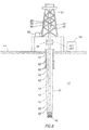
- FIG. 5 shows another example of a WDP testing device that operates outside the WDP.
- FIG. 6 shows the example device shown in FIG. 5 as it may be used with a drilling rig.
- FIG. 7 shows another example fault locating device including an external transmitter coil and a movable receiver coil insertable inside the WDP.
- FIG. 8 shows an example record with respect to depth in a wellbore of signals measured using the example shown in FIG. 7 .
- Each WDP joint 10 includes a pipe mandrel 12 having a male threaded connection (“pin”) 18 at one end and a female threaded connection (“box”) 16 at the other end.
- a shoulder 20 A on each of the pin 18 and box 16 may include a groove or channel 20 in which may be disposed a toroidal transformer coil 22 . Structure of and operation of such toroidal transformer coils to transfer signals from one joint to another are explained in U.S. Pat. No.
- Electrical conductors 24 are disposed in a suitable place within the joint 10 , such as in a longitudinally formed bore or tube (not shown) so as to protect the conductors 24 from drilling fluid that is typically pumped through a central bore or passage 14 in the center of the WDP joint 10 .
- Such passage 14 is similar to those found in conventional (not wired) joints of drill pipe known in the art.
- a fault locating device 26 may in inserted into the passage 14 and disposed in one of the joints 10 for inspection thereof.
- the example fault locating device 26 is shown in FIG. 1 as being suspended inside the joint 10 by an armored electrical cable 32 .
- the armored electrical cable may be extended from and retracted onto a winch (not shown) or similar device known in the art for spooling armored electrical cable.
- a winch not shown
- by suspending the fault locating device 26 from such a cable 32 it is possible to use the fault locating device 26 while an entire string of WDP joints 10 is deployed in a wellbore being drilled through Earth formations.
- the entire string of WDP may be evaluated by moving the fault locating device 26 along the inside of the pipe string by operating the winch (not shown).
- conveyance by a cable is not the only manner in which the fault locating device 26 may be moved through WDP joints.
- Other conveyance means known in the art include, for example, coupling the fault locating device 26 to the end of a coiled tubing, coupling the device to the end of a string of threadedly coupled rods or production tubing, or any other manner of conveyance known in the art for deploying a measuring instrument into a wellbore.
- the functional components of the fault locating device 26 shown in FIG. 1 include an electromagnetic transmitter antenna 28 and an electromagnetic receiver antenna 30 .
- the antennas 28 , 30 may be in the form of longitudinally wound wire coils, or may be any other antenna structure capable of inducing an electromagnetic field in the WDP joint 10 when electrical power is passed through the transmitter antenna 28 and capable of producing a detectable voltage in the receiver antenna 30 as a result of electromagnetic fields induced in the WDP joint 10 by the current passing through transmitter antenna 28 .
- circuitry (as will be explained in more detail with reference to FIG. 2 ) coupled to the transmitter antenna 28 causes an electromagnetic field to be induced in the WDP joint 10 .
- the electromagnetic field induces an electric current in the circuit loop created by the electrical conductors 24 and the toroidal transformer coils 22 at each end of the WDP joint 10 . Electromagnetic fields generated by such current in the circuit loop may be detected by measuring a voltage induced in the receiver antenna 30 . Based on properties of the detected voltage, the electrical integrity of the WDP joint 10 may thus be determined.
- the fault locating device 26 may include a pressure resistant housing 34 configured to traverse the interior of the WDP ( 10 in FIG. 1 ).
- the housing 34 A may define a sealable interior chamber 34 in which electronic components of the fault locating device 26 may be disposed.
- the antennas 28 , 30 which as previously explained may be longitudinally wound wire coils, may each be disposed in a respective groove or recess 28 A, 30 A formed in the exterior surface of the housing 34 .
- the wire of each antenna coil 28 , 30 may enter the chamber 34 A by a pressure sealing, electrical feedthrough bulkhead 46 .
- the electronic components in the present embodiment may include an electrical power conditioning circuit 48 that may accept electrical power transmitted from the Earth's surface along the cable 32 along one or more insulated electrical conductors (not shown separately).
- the one or more electrical conductors may also be used to communicate signals produced in the fault locating device 26 to the Earth's surface.
- a controller 36 which may be a microprocessor-based system controller, may provide operating command signals to drive the other principal components of the device 26 .
- an analog receiver amplifier 40 may be electrically coupled to the receiver antenna 30 to detect and amplify voltages induced in the receiver antenna 30 .
- the detected and amplified voltages may be digitized in an analog to digital converter (“ADC”) 38 , so that the magnitude of the voltage with respect to time will be in the form of digital words each representing the voltage magnitude.
- ADC analog to digital converter
- the output of the ADC 38 may be conducted to the controller 36 for storage and/or further processing.
- the controller 36 may store one or more current waveforms in the form of digital words.
- the current waveforms are those for alternating electrical current to be passed through the transmitter antenna 28 .
- the current waveform words may be conducted through a digital to analog converter (“DAC”) 42 to generate the analog current waveform.
- the analog current waveform may be conducted to a transmitter power amplifier 44 for driving the transmitter antenna 28 .
- FIG. 2 which includes digital signal processing circuitry, is only one possible implementation of a fault locating device according to the invention. It is also within the scope of this invention to use analog circuitry to generate the current and to detect the induced voltages.
- the current passing through the transmitter antenna 28 causes electromagnetic fields to be induced in the WDP joint, and specifically in the current loop created by the toroidal coils ( 22 in FIG. 1 ) and the electrical conductors ( 24 in FIG. 1 ).
- a voltage will be induced in the receiver antenna 30 that corresponds to the entire current loop being properly interconnected and insulated from grounding to the metal pipe mandrel ( 12 in FIG. 1 ).
- the detected voltages are then digitized in the ADC 38 , and are then communicated to the controller 36 , where the digitized detected voltages may be imparted to any known telemetry for communication to the Earth's surface.
- the example shown in FIG. 2 may have a longitudinal span 50 between the transmitter antenna 28 and the receiver antenna 30 such that antennas 28 , 30 may be spaced proximate respective ones of the toroidal coils ( 22 in FIG. 2 ) in each WDP joint ( 10 in FIG. 1 ) during inspection.
- a record is made of the voltages detected by the receiver antenna 30 . If any WDP joint has an open circuit, such that the current loop described above is not complete, then the magnitude of the detected voltage will be relatively small or zero. If a WDP joint has a short circuit, the detected voltage will be small or zero when the respective antennas 28 , 30 are disposed proximate the ends of the WDP joint. It will be appreciated that under such conditions it could be difficult to distinguish between an open circuit and a short circuit in the WDP joint. Therefore, other examples of a fault locating device according to the invention may have different and/or selectable span between the transmitter antenna and the receiver antenna.
- the detected signal would be approximately zero for the entire pipe segment being investigated. If there were a short between the conductors, however, the current would be induced in the upper part of the segment, and there would be a non-zero signal until the receiver moved past the position of the short circuit. In this respect, the detected signal could be used to identify the type of fault (short or open) and the location of the fault with in the pipe segment in the case of a short circuit.
- FIG. 3 shows another possible example of a fault locating device 26 A having a selectable longitudinal span between the transmitter antenna 28 and the receiver antenna 30 .
- the housing consists of two slidably engaged housing segments 34 A, 34 B.
- the transmitter antenna 28 may be formed on or affixed to one segment 34 A while the receiver antenna 30 may be formed on or affixed to the other segment 30 B.
- FIG. 4 Another example of a fault locating device 26 B having a selectable span between the transmitter antenna and the receiver antenna is shown in FIG. 4 .
- the housing 34 may be similar to that explained with reference to FIG. 2 .
- the fault locating device 26 B may include a plurality of receiver antennas shown at 30 A, 30 B, 30 C, 30 D disposed on or affixed to the housing 34 at longitudinally spaced apart positions.
- the receiver amplifier ( 40 in FIG. 2 ) may be preceded by a multiplexer (not shown) or similar switch to select the one of the receiver antennas 30 A- 30 D to be interrogated at any point in time.
- One or more of the receiver antennas 30 A- 30 B may be used at the same time to interrogate a section of WDP.
- the transmitter to receiver span is initially set to match the span between the toroidal coils ( 22 in FIG. 1 ) in the typical WDP joint.
- the span between the transmitter antenna 28 and the receiver antenna may be selected, as in FIG. 3 by sliding the housing segment 34 B to shorten the span until a detectable voltage is found, or as shown in FIG. 4 , by selecting successively shorter spaced receiver antennas 30 D, 30 C, 30 B, 30 A until a detectable voltage is found.
- the position of a short circuit in a WDP joint my thus be determined.
- the longitudinal span ( 50 in FIG. 2 ) of the fault locating device 26 is not limited to only the span between the ends of one WDP joint as shown in FIG. 1 . It is clearly within the scope of the present invention to provide a fault locating device having a span of the lengths of two or more WDP joints ( 10 in FIG. 1 ).
- a fault locating device may have a span that is about equal to the length of three segments of WDP joints. In this manner, a fault locating device may be used to narrow the location of the fault in the WDP system. It is noted that a fault locating device with a span of two, or four or more segments is also possible.
- FIG. 5 shows another example of such a fault locating device 26 C.
- a mandrel 34 B which in the present embodiment may be made from electrically non-conductive, non magnetic material such as glass fiber reinforced plastic, may include a transmitter antenna 28 A and receiver antenna 30 B which may be longitudinally wound wire coils substantially as explained with reference to FIG. 2 .
- the circuitry to actuate the transmitter antenna 28 B and receiver antenna 30 B which also may be substantially as explained with reference to FIG. 2 .
- the device shown in FIG. 5 may have particular application on or near the floor of a drilling unit, such that as the WDP string is assembled or “made up” and is lowered into the wellbore, the individual joints of WDP will pass through the device shown in FIG. 5 for inspection during the “trip” into the wellbore. The WDP joints may be inspected again as the WDP string is withdrawn from the wellbore. Variations on the device shown in FIG. 5 that include features for changing the longitudinal span ( 50 in FIG. 2 ) between the transmitter antenna 28 B and the receiver antenna 30 B may be also used with the example fault locating device 26 C shown in FIG. 5 .
- a string of WDP joints 10 coupled end to end is shown suspended by a top drive 52 (or kelly on drilling units so equipped).
- the top drive 52 may be raised and lowered by a hook 48 coupled to a hoisting system consisting of drawworks 50 , drill line 55 , upper sheave 51 and lower sheave 53 of types well known in the art. All the foregoing components are associated with a drilling unit 46 .
- a fault locating device 26 substantially as explained with reference to FIG. 5 may be disposed in a convenient location with respect to the drilling unit 46 , such that as the pipe string is moved upwardly or downwardly, the various WDP joints 10 may move through the device 26 for evaluation.
- a drill bit 40 is disposed at the lower end of the string of WDP joints 10 and drills a wellbore 42 through subterranean Earth formations 41 .
- the drill bit 40 is rotated by operating the top drive 52 to turn the pipe string, or alternatively by pumping fluid through a drilling motor (not shown) typically located in the pipe string near the drill bit 40 .
- a drilling motor typically located in the pipe string near the drill bit 40 .
- the pipe string is continuously lowered by operating the drawworks 50 to release the drill line 55 .
- Such operation maintains a selected portion of the weight of the pipe string on the drill bit 40 .
- successive ones of the WDP joints 10 move through the interior of the fault locating device 26 C. Once inside, the transmitter and receiver antenna may be activated to interrogate the WDP section that is disposed within the fault locating device 26 C.
- the evaluation may continue as the pipe string is withdrawn from the wellbore 42 .
- Circuitry such as explained with reference to FIG. 2 may be disposed in a recording unit 54 , which may include other systems (not shown) for recording an interpretation of measurements made by the fault locating device 26 .
- a device such as shown in FIG. 2 may be lowered inside the pipe string at the end of an electrical cable, substantially as explained with reference to FIGS. 1 and 2 .
- a device as shown in FIG. 2 and as explained above inside the pipe string while it is suspended in the wellbore 42 it may be possible to locate the particular WDP joint 10 where the fault is located. Such location may eliminate the need to remove the entire pipe string from the wellbore 42 and test each WDP joint 10 individually.
- the fault locating device 26 shown in FIG. 6 may be used while withdrawing the pipe string from the wellbore 42 until the failed WDP joint 10 is located.
- FIG. 7 Another example fault locating device is shown in FIG. 7 .
- the example device shown in FIG. 7 includes a transmitter 26 A similar to the example shown in and explained with reference to FIG. 6 .
- Such transmitter 26 A may be disposed below the drill floor of the drilling unit (or any other convenience location) and may be disposed outside the WDP joints 10 .
- a receiver 26 B may include one or more receiver coils 26 C disposed on a sonde mandrel. The receiver 26 B may be moved along the interior of the WDP joints 10 by an armored electrical cable 27 coupled to one end of the receiver 26 B.
- the transmitter may be energized as explained above with reference to other example devices, and a record with respect to depth of voltage induced in the one or more receiver coils 26 C may be made.
- the position of a fault such as an open or short circuit may be inferred from the record of voltage measurements.
- FIG. 8 is a graph (or “log”) at 80 of detected voltage with respect to depth in the wellbore of the receiver ( 26 B in FIG. 7 ).
- the detected voltage amplitude 80 exhibits peaks 82 , 84 , 86 , 88 , 90 of decreasing amplitude that correspond to the location along the WDP of connections between successive WDP joints ( 10 in FIG. 7 ). It can also be observed in FIG. 8 that the amplitude of the signal decreases with depth, and correspondingly, as the transmitter ( 26 A in FIG. 7 ) and receiver ( 26 B in FIG. 7 ) become more spaced apart.
- a log may be made of the receiver signal when drilling the wellbore begins.
- a log may be made of the receiver signal at selected times during drilling operations. Changes in the signal amplitude between successive logs above a selected threshold may indicate an impending fault in the WDP that requires intervention.
- any of the foregoing examples intended to be moved through the interior of a string of WDP may have electrical power supplied thereto by an armored electrical cable, or may include internal electrical power such as may be supplied by batteries.
- such devices may be powered by a fluid operated turbine/generator combination as will be familiar to those skilled in he art as being used with MWD and/or LWD instrumentation.
- Such examples may include internal data storage that can be interrogated when he device is withdrawn from the interior of the WDP, or signals generated by the device may be communicated over the armored electrical cable where such cable is used.
- multiple receiver antenna example such as shown in FIG. 4 may be substituted by multiple transmitter antennas each or selectively coupled to the source of alternating current.
- the example explained with reference to FIG. 7 may also be substituted by a receiver in the position where the transmitter is shown below the rig floor, and the receiver inside the WDP may be substituted by one or more transmitters.
- transmitter transmitting
- transmitter antenna in the description and claims that follow may be substituted by “receiver”, “receiving” or “receiver antenna” where such reference defines location of a particular antenna or act performed through an antenna.
- the opposite substitution may be made with reference herein to “receiver”, “receiving” or “receiver antenna.”
Abstract
Description
Claims (21)
Priority Applications (8)
| Application Number | Priority Date | Filing Date | Title |
|---|---|---|---|
| US11/648,139 US8072347B2 (en) | 2006-12-29 | 2006-12-29 | Method and apparatus for locating faults in wired drill pipe |
| GB0712207A GB2445203B (en) | 2006-12-29 | 2007-06-23 | Method and apparatus for locating faults in wired drill pipe |
| CA2594606A CA2594606C (en) | 2006-12-29 | 2007-07-24 | Method and apparatus for locating faults in wired drill pipe |
| MX2007008963A MX2007008963A (en) | 2006-12-29 | 2007-07-25 | Method and apparatus for locating faults in wired drill pipe. |
| RU2007128774/28A RU2436109C2 (en) | 2006-12-29 | 2007-07-26 | Procedure and instrument for detection of position of fault in cable drill pipe |
| DE102007035356A DE102007035356A1 (en) | 2006-12-29 | 2007-07-27 | A method of determining the electrical condition of a wired drill pipe and fault locator |
| CNA2007101527604A CN101210489A (en) | 2006-12-29 | 2007-09-20 | Method and apparatus for locating faults in wired drill pipe |
| FR0759737A FR2910923B1 (en) | 2006-12-29 | 2007-12-11 | METHOD AND APPARATUS FOR LOCATING FAILURES IN A CABLE DRILLING ROD |
Applications Claiming Priority (1)
| Application Number | Priority Date | Filing Date | Title |
|---|---|---|---|
| US11/648,139 US8072347B2 (en) | 2006-12-29 | 2006-12-29 | Method and apparatus for locating faults in wired drill pipe |
Publications (2)
| Publication Number | Publication Date |
|---|---|
| US20080158005A1 US20080158005A1 (en) | 2008-07-03 |
| US8072347B2 true US8072347B2 (en) | 2011-12-06 |
Family
ID=38352806
Family Applications (1)
| Application Number | Title | Priority Date | Filing Date |
|---|---|---|---|
| US11/648,139 Active 2030-10-05 US8072347B2 (en) | 2006-12-29 | 2006-12-29 | Method and apparatus for locating faults in wired drill pipe |
Country Status (8)
| Country | Link |
|---|---|
| US (1) | US8072347B2 (en) |
| CN (1) | CN101210489A (en) |
| CA (1) | CA2594606C (en) |
| DE (1) | DE102007035356A1 (en) |
| FR (1) | FR2910923B1 (en) |
| GB (1) | GB2445203B (en) |
| MX (1) | MX2007008963A (en) |
| RU (1) | RU2436109C2 (en) |
Cited By (9)
| Publication number | Priority date | Publication date | Assignee | Title |
|---|---|---|---|---|
| US20090289808A1 (en) * | 2008-05-23 | 2009-11-26 | Martin Scientific Llc | Reliable downhole data transmission system |
| US20120108171A1 (en) * | 2010-10-28 | 2012-05-03 | Sondex Limited | Telemetry Conveyed by Pipe Utilizing Specks |
| US8941384B2 (en) | 2009-01-02 | 2015-01-27 | Martin Scientific Llc | Reliable wired-pipe data transmission system |
| US9057799B2 (en) | 2012-03-19 | 2015-06-16 | Baker Hughes Incorporated | Induction logging signals and directional guidance antenna systems |
| US9063244B2 (en) | 2012-03-19 | 2015-06-23 | Baker Hughes Incorporated | Induction logging signals using complex waveforms and directional guidance antenna systems |
| US20150361784A1 (en) * | 2014-06-13 | 2015-12-17 | Smith International, Inc. | Testing of drill pipe inspection equipment |
| US10218074B2 (en) | 2015-07-06 | 2019-02-26 | Baker Hughes Incorporated | Dipole antennas for wired-pipe systems |
| US10241227B2 (en) | 2012-04-27 | 2019-03-26 | Baker Hughes, A Ge Company, Llc | Method and apparatus to detect formation boundaries ahead of the bit using multiple toroidal coils |
| US10329856B2 (en) | 2015-05-19 | 2019-06-25 | Baker Hughes, A Ge Company, Llc | Logging-while-tripping system and methods |
Families Citing this family (11)
| Publication number | Priority date | Publication date | Assignee | Title |
|---|---|---|---|---|
| US8049506B2 (en) | 2009-02-26 | 2011-11-01 | Aquatic Company | Wired pipe with wireless joint transceiver |
| AT508306B1 (en) * | 2009-06-08 | 2013-01-15 | Advanced Drilling Solutions Gmbh | CONNECTION BETWEEN A STARTER EAR AND A CONNECTOR |
| CN102953690A (en) * | 2011-08-31 | 2013-03-06 | 中国石油化工股份有限公司 | Wired communication screw rod |
| AT511991B1 (en) * | 2011-09-26 | 2013-09-15 | Advanced Drilling Solutions Gmbh | METHOD AND DEVICE FOR SUPPLYING AT LEAST ONE ELECTRIC CONSUMER A DRILLING RACK WITH AN OPERATING VOLTAGE |
| US20140062716A1 (en) * | 2012-08-28 | 2014-03-06 | Intelliserv, Llc | System and method for determining fault location |
| US9273550B2 (en) * | 2012-08-28 | 2016-03-01 | Intelliserv, Llc | System and method for determining fault location |
| DE202013100435U1 (en) * | 2012-09-11 | 2013-02-13 | Ipek International Gmbh | System for video data transmission in pipelines |
| CN104847282A (en) * | 2015-05-12 | 2015-08-19 | 天津商业大学 | Special buckle oil casing sealing structure |
| US20170059637A1 (en) * | 2015-08-28 | 2017-03-02 | Schlumberger Technology Corporation | Detecting and accounting for fault conditions affecting electronic devices |
| WO2017091193A1 (en) * | 2015-11-23 | 2017-06-01 | Halliburton Energy Services, Inc. | Switchable multi-antenna fluid sensing |
| CN105604496B (en) * | 2015-12-24 | 2017-12-05 | 中国石油天然气集团公司 | A kind of measuring method and system for having cable drilling rod channel parameter |
Citations (11)
| Publication number | Priority date | Publication date | Assignee | Title |
|---|---|---|---|---|
| US3807502A (en) | 1973-04-12 | 1974-04-30 | Exxon Production Research Co | Method for installing an electric conductor in a drill string |
| US3957118A (en) | 1974-09-18 | 1976-05-18 | Exxon Production Research Company | Cable system for use in a pipe string and method for installing and using the same |
| US4126848A (en) | 1976-12-23 | 1978-11-21 | Shell Oil Company | Drill string telemeter system |
| US4763520A (en) * | 1985-02-11 | 1988-08-16 | Comdisco Resources, Inc. | Method and means for obtaining data representing a parameter of fluid flowing through a down hole side of an oil or gas well bore |
| US20020112852A1 (en) | 2000-11-10 | 2002-08-22 | Baker Hughes Inc. | Integrated modular connector in a drill pipe |
| US6670880B1 (en) | 2000-07-19 | 2003-12-30 | Novatek Engineering, Inc. | Downhole data transmission system |
| US20040217880A1 (en) * | 2003-04-29 | 2004-11-04 | Brian Clark | Method and apparatus for performing diagnostics in a wellbore operation |
| GB2405479A (en) | 2003-08-29 | 2005-03-02 | Schlumberger Holdings | Method and apparatus for performing diagnostics on a downhole telemetry system |
| US20050087368A1 (en) * | 2003-10-22 | 2005-04-28 | Boyle Bruce W. | Downhole telemetry system and method |
| US20050212530A1 (en) | 2004-03-24 | 2005-09-29 | Hall David R | Method and Apparatus for Testing Electromagnetic Connectivity in a Drill String |
| US20100116550A1 (en) * | 2005-08-04 | 2010-05-13 | Remi Hutin | Interface and method for wellbore telemetry system |
Family Cites Families (1)
| Publication number | Priority date | Publication date | Assignee | Title |
|---|---|---|---|---|
| US6641434B2 (en) * | 2001-06-14 | 2003-11-04 | Schlumberger Technology Corporation | Wired pipe joint with current-loop inductive couplers |
-
2006
- 2006-12-29 US US11/648,139 patent/US8072347B2/en active Active
-
2007
- 2007-06-23 GB GB0712207A patent/GB2445203B/en active Active
- 2007-07-24 CA CA2594606A patent/CA2594606C/en active Active
- 2007-07-25 MX MX2007008963A patent/MX2007008963A/en active IP Right Grant
- 2007-07-26 RU RU2007128774/28A patent/RU2436109C2/en active
- 2007-07-27 DE DE102007035356A patent/DE102007035356A1/en not_active Withdrawn
- 2007-09-20 CN CNA2007101527604A patent/CN101210489A/en active Pending
- 2007-12-11 FR FR0759737A patent/FR2910923B1/en active Active
Patent Citations (13)
| Publication number | Priority date | Publication date | Assignee | Title |
|---|---|---|---|---|
| US3807502A (en) | 1973-04-12 | 1974-04-30 | Exxon Production Research Co | Method for installing an electric conductor in a drill string |
| US3957118A (en) | 1974-09-18 | 1976-05-18 | Exxon Production Research Company | Cable system for use in a pipe string and method for installing and using the same |
| US4126848A (en) | 1976-12-23 | 1978-11-21 | Shell Oil Company | Drill string telemeter system |
| US4763520A (en) * | 1985-02-11 | 1988-08-16 | Comdisco Resources, Inc. | Method and means for obtaining data representing a parameter of fluid flowing through a down hole side of an oil or gas well bore |
| US6670880B1 (en) | 2000-07-19 | 2003-12-30 | Novatek Engineering, Inc. | Downhole data transmission system |
| US20020112852A1 (en) | 2000-11-10 | 2002-08-22 | Baker Hughes Inc. | Integrated modular connector in a drill pipe |
| US20040217880A1 (en) * | 2003-04-29 | 2004-11-04 | Brian Clark | Method and apparatus for performing diagnostics in a wellbore operation |
| US7096961B2 (en) | 2003-04-29 | 2006-08-29 | Schlumberger Technology Corporation | Method and apparatus for performing diagnostics in a wellbore operation |
| GB2405479A (en) | 2003-08-29 | 2005-03-02 | Schlumberger Holdings | Method and apparatus for performing diagnostics on a downhole telemetry system |
| US20050046591A1 (en) * | 2003-08-29 | 2005-03-03 | Nicolas Pacault | Method and apparatus for performing diagnostics on a downhole communication system |
| US20050087368A1 (en) * | 2003-10-22 | 2005-04-28 | Boyle Bruce W. | Downhole telemetry system and method |
| US20050212530A1 (en) | 2004-03-24 | 2005-09-29 | Hall David R | Method and Apparatus for Testing Electromagnetic Connectivity in a Drill String |
| US20100116550A1 (en) * | 2005-08-04 | 2010-05-13 | Remi Hutin | Interface and method for wellbore telemetry system |
Non-Patent Citations (1)
| Title |
|---|
| UK Search Report Application No. GB0712207.0 dated Oct. 4, 2007. |
Cited By (17)
| Publication number | Priority date | Publication date | Assignee | Title |
|---|---|---|---|---|
| US9133707B2 (en) | 2008-05-23 | 2015-09-15 | Martin Scientific LLP | Reliable downhole data transmission system |
| US9422808B2 (en) | 2008-05-23 | 2016-08-23 | Martin Scientific, Llc | Reliable downhole data transmission system |
| US20090289808A1 (en) * | 2008-05-23 | 2009-11-26 | Martin Scientific Llc | Reliable downhole data transmission system |
| US8704677B2 (en) | 2008-05-23 | 2014-04-22 | Martin Scientific Llc | Reliable downhole data transmission system |
| US8242928B2 (en) | 2008-05-23 | 2012-08-14 | Martin Scientific Llc | Reliable downhole data transmission system |
| US8941384B2 (en) | 2009-01-02 | 2015-01-27 | Martin Scientific Llc | Reliable wired-pipe data transmission system |
| US9903197B2 (en) | 2009-01-02 | 2018-02-27 | Baker Hughes, A Ge Company, Llc | Reliable wired-pipe data transmission system |
| US20120108171A1 (en) * | 2010-10-28 | 2012-05-03 | Sondex Limited | Telemetry Conveyed by Pipe Utilizing Specks |
| US8639186B2 (en) * | 2010-10-28 | 2014-01-28 | Sondex Wireline Limited | Telemetry conveyed by pipe utilizing specks |
| US9057799B2 (en) | 2012-03-19 | 2015-06-16 | Baker Hughes Incorporated | Induction logging signals and directional guidance antenna systems |
| US9063244B2 (en) | 2012-03-19 | 2015-06-23 | Baker Hughes Incorporated | Induction logging signals using complex waveforms and directional guidance antenna systems |
| US10241227B2 (en) | 2012-04-27 | 2019-03-26 | Baker Hughes, A Ge Company, Llc | Method and apparatus to detect formation boundaries ahead of the bit using multiple toroidal coils |
| US20150361784A1 (en) * | 2014-06-13 | 2015-12-17 | Smith International, Inc. | Testing of drill pipe inspection equipment |
| US10209221B2 (en) * | 2014-06-13 | 2019-02-19 | Schlumberger Technology Corporation | Testing of drill pipe inspection equipment |
| US10329856B2 (en) | 2015-05-19 | 2019-06-25 | Baker Hughes, A Ge Company, Llc | Logging-while-tripping system and methods |
| US10995567B2 (en) | 2015-05-19 | 2021-05-04 | Baker Hughes, A Ge Company, Llc | Logging-while-tripping system and methods |
| US10218074B2 (en) | 2015-07-06 | 2019-02-26 | Baker Hughes Incorporated | Dipole antennas for wired-pipe systems |
Also Published As
| Publication number | Publication date |
|---|---|
| GB2445203A (en) | 2008-07-02 |
| FR2910923B1 (en) | 2013-12-27 |
| DE102007035356A1 (en) | 2008-07-03 |
| GB0712207D0 (en) | 2007-08-01 |
| RU2007128774A (en) | 2009-02-10 |
| CA2594606C (en) | 2013-01-29 |
| FR2910923A1 (en) | 2008-07-04 |
| CN101210489A (en) | 2008-07-02 |
| RU2436109C2 (en) | 2011-12-10 |
| US20080158005A1 (en) | 2008-07-03 |
| CA2594606A1 (en) | 2008-06-29 |
| GB2445203B (en) | 2009-05-20 |
| MX2007008963A (en) | 2009-01-09 |
Similar Documents
| Publication | Publication Date | Title |
|---|---|---|
| US8072347B2 (en) | Method and apparatus for locating faults in wired drill pipe | |
| US6950034B2 (en) | Method and apparatus for performing diagnostics on a downhole communication system | |
| US7389183B2 (en) | Method for determining a stuck point for pipe, and free point logging tool | |
| CN101517191B (en) | Method of and system for determining the free point in a drill pipe | |
| US9850753B2 (en) | Cable integrity monitor for electromagnetic telemetry systems | |
| US5168942A (en) | Resistivity measurement system for drilling with casing | |
| US8136591B2 (en) | Method and system for using wireline configurable wellbore instruments with a wired pipe string | |
| US20090078413A1 (en) | Wireless casing collar locator | |
| US9347277B2 (en) | System and method for communicating between a drill string and a logging instrument | |
| US8322433B2 (en) | Wired slip joint | |
| US8079414B2 (en) | Electromagnetic free point tool and methods of use | |
| US20080159077A1 (en) | Cable link for a wellbore telemetry system | |
| US8708041B2 (en) | Method and system for using wireline configurable wellbore instruments with a wired pipe string | |
| US9063250B2 (en) | Interference testing while drilling | |
| US5533572A (en) | System and method for measuring corrosion in well tubing | |
| US20140216734A1 (en) | Casing collar location using elecromagnetic wave phase shift measurement | |
| MX2007008201A (en) | Short circuit protection for serially connected nodes in a hdyrocarbon exploration or production electrical system. | |
| US9605528B2 (en) | Distributed sensing with a multi-phase drilling device | |
| EP0196829A2 (en) | Well tool | |
| WO2022260725A1 (en) | Downhole tubular inspection combining partial saturation and remote field eddy currents |
Legal Events
| Date | Code | Title | Description |
|---|---|---|---|
| AS | Assignment |
Owner name: SCHLUMBERGER TECHNOLOGY CORPORATION, TEXAS Free format text: ASSIGNMENT OF ASSIGNORS INTEREST;ASSIGNORS:SANTOSO, DAVID;RENDUSARA, DUDI;NAKAJIMA, HIROSHI;AND OTHERS;REEL/FRAME:019042/0959;SIGNING DATES FROM 20070111 TO 20070316 Owner name: SCHLUMBERGER TECHNOLOGY CORPORATION, TEXAS Free format text: ASSIGNMENT OF ASSIGNORS INTEREST;ASSIGNORS:SANTOSO, DAVID;RENDUSARA, DUDI;NAKAJIMA, HIROSHI;AND OTHERS;SIGNING DATES FROM 20070111 TO 20070316;REEL/FRAME:019042/0959 |
|
| AS | Assignment |
Owner name: INTELLISERV, LLC,TEXAS Free format text: ASSIGNMENT OF ASSIGNORS INTEREST;ASSIGNOR:SCHLUMBERGER TECHNOLOGY CORPORATION;REEL/FRAME:023953/0285 Effective date: 20090924 Owner name: INTELLISERV, LLC, TEXAS Free format text: ASSIGNMENT OF ASSIGNORS INTEREST;ASSIGNOR:SCHLUMBERGER TECHNOLOGY CORPORATION;REEL/FRAME:023953/0285 Effective date: 20090924 |
|
| STCF | Information on status: patent grant |
Free format text: PATENTED CASE |
|
| FPAY | Fee payment |
Year of fee payment: 4 |
|
| MAFP | Maintenance fee payment |
Free format text: PAYMENT OF MAINTENANCE FEE, 8TH YEAR, LARGE ENTITY (ORIGINAL EVENT CODE: M1552); ENTITY STATUS OF PATENT OWNER: LARGE ENTITY Year of fee payment: 8 |
|
| MAFP | Maintenance fee payment |
Free format text: PAYMENT OF MAINTENANCE FEE, 12TH YEAR, LARGE ENTITY (ORIGINAL EVENT CODE: M1553); ENTITY STATUS OF PATENT OWNER: LARGE ENTITY Year of fee payment: 12 |