US8073336B2 - Entanglement-based QKD system with active phase tracking - Google Patents
Entanglement-based QKD system with active phase tracking Download PDFInfo
- Publication number
- US8073336B2 US8073336B2 US12/223,308 US22330807A US8073336B2 US 8073336 B2 US8073336 B2 US 8073336B2 US 22330807 A US22330807 A US 22330807A US 8073336 B2 US8073336 B2 US 8073336B2
- Authority
- US
- United States
- Prior art keywords
- phase
- wavelength
- pulses
- entangled
- charlie
- Prior art date
- Legal status (The legal status is an assumption and is not a legal conclusion. Google has not performed a legal analysis and makes no representation as to the accuracy of the status listed.)
- Expired - Fee Related, expires
Links
- 230000003287 optical effect Effects 0.000 claims abstract description 28
- 238000000034 method Methods 0.000 claims abstract description 14
- 230000006641 stabilisation Effects 0.000 claims abstract description 12
- 238000011105 stabilization Methods 0.000 claims abstract description 12
- 238000012937 correction Methods 0.000 claims abstract description 6
- 239000013307 optical fiber Substances 0.000 claims description 33
- ZPUCINDJVBIVPJ-LJISPDSOSA-N cocaine Chemical compound O([C@H]1C[C@@H]2CC[C@@H](N2C)[C@H]1C(=O)OC)C(=O)C1=CC=CC=C1 ZPUCINDJVBIVPJ-LJISPDSOSA-N 0.000 claims description 22
- 238000006243 chemical reaction Methods 0.000 claims description 11
- 238000002360 preparation method Methods 0.000 claims description 5
- 230000008569 process Effects 0.000 claims description 4
- 230000001427 coherent effect Effects 0.000 abstract description 8
- 230000001934 delay Effects 0.000 abstract description 3
- 230000002269 spontaneous effect Effects 0.000 abstract description 2
- 238000001514 detection method Methods 0.000 description 5
- 238000004891 communication Methods 0.000 description 4
- 238000010586 diagram Methods 0.000 description 4
- 230000008878 coupling Effects 0.000 description 3
- 238000010168 coupling process Methods 0.000 description 3
- 238000005859 coupling reaction Methods 0.000 description 3
- 238000012986 modification Methods 0.000 description 3
- 230000004048 modification Effects 0.000 description 3
- 238000010276 construction Methods 0.000 description 2
- 238000005259 measurement Methods 0.000 description 2
- 238000012360 testing method Methods 0.000 description 2
- 208000022673 Distal myopathy, Welander type Diseases 0.000 description 1
- 230000018199 S phase Effects 0.000 description 1
- 208000034384 Welander type distal myopathy Diseases 0.000 description 1
- 238000010521 absorption reaction Methods 0.000 description 1
- 230000004913 activation Effects 0.000 description 1
- 230000003321 amplification Effects 0.000 description 1
- 230000008901 benefit Effects 0.000 description 1
- 230000007423 decrease Effects 0.000 description 1
- 238000011161 development Methods 0.000 description 1
- 230000007613 environmental effect Effects 0.000 description 1
- 239000000835 fiber Substances 0.000 description 1
- 230000008570 general process Effects 0.000 description 1
- GQYHUHYESMUTHG-UHFFFAOYSA-N lithium niobate Chemical compound [Li+].[O-][Nb](=O)=O GQYHUHYESMUTHG-UHFFFAOYSA-N 0.000 description 1
- 230000008450 motivation Effects 0.000 description 1
- 238000003199 nucleic acid amplification method Methods 0.000 description 1
- WYOHGPUPVHHUGO-UHFFFAOYSA-K potassium;oxygen(2-);titanium(4+);phosphate Chemical compound [O-2].[K+].[Ti+4].[O-]P([O-])([O-])=O WYOHGPUPVHHUGO-UHFFFAOYSA-K 0.000 description 1
- 238000012545 processing Methods 0.000 description 1
- 230000005855 radiation Effects 0.000 description 1
- 238000005070 sampling Methods 0.000 description 1
Images

Classifications
-
- H—ELECTRICITY
- H04—ELECTRIC COMMUNICATION TECHNIQUE
- H04B—TRANSMISSION
- H04B10/00—Transmission systems employing electromagnetic waves other than radio-waves, e.g. infrared, visible or ultraviolet light, or employing corpuscular radiation, e.g. quantum communication
- H04B10/70—Photonic quantum communication
-
- H—ELECTRICITY
- H04—ELECTRIC COMMUNICATION TECHNIQUE
- H04L—TRANSMISSION OF DIGITAL INFORMATION, e.g. TELEGRAPHIC COMMUNICATION
- H04L9/00—Cryptographic mechanisms or cryptographic arrangements for secret or secure communications; Network security protocols
- H04L9/08—Key distribution or management, e.g. generation, sharing or updating, of cryptographic keys or passwords
- H04L9/0816—Key establishment, i.e. cryptographic processes or cryptographic protocols whereby a shared secret becomes available to two or more parties, for subsequent use
- H04L9/0852—Quantum cryptography
Definitions
- the present invention relates to quantum cryptography, and in particular relates to quantum key distribution (QKD) systems and methods using entangled photons.
- QKD quantum key distribution
- Quantum cryptography The general principles of quantum cryptography were first set forth by Bennett and Brassard in their article “Quantum Cryptography: Public key distribution and coin tossing,” Proceedings of the International Conference on Computers, Systems and Signal Processing, Bangalore, India, 1984, pp. 175-179 (IEEE, New York, 1984).
- QKD quantum key distribution
- Quantum key distribution involves establishing a key between a sender (“Alice”) and a receiver (“Bob”) by using weak (i.e., 1 photon or less, on average, and typically 0.1 photon on average) optical signals or “qubits” transmitted over a “quantum channel.”
- weak i.e., 1 photon or less, on average, and typically 0.1 photon on average
- quantum channel optical signals or “qubits” transmitted over a “quantum channel.”
- the security of the key distribution is based on the quantum mechanical principle that any measurement of a quantum system in an unknown state will modify its state.
- an eavesdropper (“Eve”) that attempts to intercept or otherwise measure the exchanged qubits will introduce errors that reveal her presence.
- Ekert proposed a QKD scheme based on entangled photons shared by Alice and Bob, (see A. K. Ekert. “Quantum cryptography based on Bell's theorem”, Phys. Rev. Lett., vol. 67 pp. 661-663, (1991) (hereinafter, “Ekert”) which article is incorporated by reference herein).
- Alice and Bob also can check so-called Bell inequality to reveal the presence of the eavesdropper.
- the Ekert protocol provides an additional security level as compared to the BB84 protocol.
- the method includes generating in an initial state preparation stage (“Charlie”) pairs of coherent photons at a first wavelength, such as a known telecommunications wavelength.
- the method uses second harmonic generation followed by spontaneous parametric downconversion to generate entangled photon pairs having the first wavelength.
- a phase loop in Charlie is used to provide a phase delay between the first-wavelength coherent “pump” photons.
- State detection stages (Alice and Bob) are optically coupled to Charlie and each receive respective entangled photons from Charlie. These photons are given respective second and third phase delays by respective phase delay loops in Alice and Bob.
- the relative phase delays are tracked using reference optical signals generated by Charlie and that traverse the three phase loops.
- Classical photodetectors are used to detect the reference signal and a control unit is used to generate a phase-correction signal that maintains the relative phases of the three phase delay loops.
- Pairs of single-photon detectors are used at Alice and Bob to measure the state of each entangled photon.
- a standard QKD protocol e.g., Ekert91
- Ekert91 is then followed to establish a quantum key between Alice and Bob.
- An example embodiment of the system of the present invention includes three phase-delay loops each formed from optical components used for the popular telecom wavelength of 1550 nm, thereby making the system cost-effective as well as efficient in transmitting light due to the low optical-fiber absorption at this wavelength.
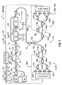
- FIG. 1 is a schematic diagram of an example embodiment of a entanglement-based QKD system with active interferometers stabilization according to the present invention.
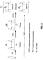
- FIG. 2 is a schematic timing diagram illustrating the generation of photons P 5 from each pulse P 1 from the system of FIG. 1 , also illustrating the relative phases associated with each optical fiber loop that the corresponding pulses encounter.
- the present invention relates to quantum cryptography, an in particular relates to quantum key distribution (QKD) systems and methods using entangled photons.
- QKD quantum key distribution
- the present invention improves upon the QKD system disclosed in Brendel, and utilizes the stabilization method disclosed in the pending PCT patent application publication serial no. PCT/US04/040991, entitled “Active stabilization of a one-way QKD system,” which PCT patent application is incorporated by reference herein.
- the invention allows state preparation and state detection at one telecommunication (“telecom”) wavelength, plus convenient stabilization and synchronization of three QKD stations.
- optical coupling between elements of the system is accomplished using sections of optical fiber.
- FIG. 1 is a schematic diagram of an example embodiment of an entanglement-based QKD system 20 according to the present invention.
- System 20 includes three different QKD station, Charlie, Alice and Bob. Charlie is the state-preparation station, while Alice and Bob are the state-measurement stations.
- lasers 22 and/or 24 are pulse gain-switched diode lasers that emit light (pulses P 1 and P 2 , respectively) of different wavelengths ⁇ 22 and ⁇ 24 for reasons discussed below.
- an optical amplifier 30 such as an erbium-doped fiber amplifier (EDFA) for 1550 nm light, is optically coupled to laser 22 .
- Lasers 22 and 24 are optically coupled to a wavelength division multiplexer (WDM) 36 .
- WDM wavelength division multiplexer
- Charlie also includes an optical loop 40 optically coupled to WDM 36 .
- Loop 40 is formed from two beam splitters 42 and 43 and two sections of optical fiber 45 and 47 optically coupled at respective opposite ends to the beam splitters.
- Optical fiber sections 45 and 47 have different lengths and representing different “arms” of the loop so that loop 40 acts as a delay loop for optical pulses traversing the different optical fiber sections.
- One of the arms (say 47 ) includes an adjustable phase delay element MC, such as a phase modulator.
- Charlie also includes a main control unit C operatively coupled to phase-delay element MC and to lasers 22 and 24 .
- Phase-delay element MC is controlled by main control unit C via a control signal SCM so that the overall phase ⁇ 40 of optical fiber loop 40 can be set (adjusted) to a desired value.
- Charlie further includes a WDM 49 optically coupled to beam splitter 43 via an optical fiber section F 1 .
- a frequency-doubling element 50 is optically coupled to WDM 49 .
- frequency-doubling element 50 includes a periodically-poled lithium niobate (PPLN) waveguide that performs frequency doubling via second harmonic generation (SHG).
- An optical filter 60 is optically coupled to and arranged optically downstream of frequency-doubling element 50 to filter out any radiation whose frequency was not doubled by the frequency-doubling element.
- Charlie also includes an entangled-photon generator 70 optically coupled to and arranged optically downstream of optical filter 60 .
- Entangled-photon generator 70 is also optically coupled to a WDM 74 .
- entangled-photon generator includes a periodically poled potassium titanyl phosphate waveguide (PPKTP WG).
- PPKTP WG periodically poled potassium titanyl phosphate waveguide
- PPLN and PPKTP waveguides are based on the high non-linearity of PPLN (Type I o-o-o) and the good optical quality of the modes of PPKTP WG recently observed (see Trifonov and Zavriyev, “Secure communication with a heralded single-photon source”, J. Optics B: Quantum and Semiclassical Optics, 7 (2005) S772-S777). Good optical mode quality is necessary for efficient coupling of downconverted photons into the optical fiber.
- Other types of waveguides can also be used to obtain high coupling efficiency.
- Frequency-doubling element, filter 60 and entangled-photon generator 70 constitute an “up-down conversion section” 21 of system 20 that first increases the frequency of the light pulses and then decreases the frequency of the light pulses so that the quantum signals (i.e., entangled photons P 5 ) used to perform QKD have the same (or substantially the same) wavelength as the original pump pulses P 1 .
- Charlie also includes an optical fiber section 52 optically coupled WDM 49 and to WDM 54 .
- Optical fiber section 52 serves as an optical path for bypassing up-down section 21 , for reasons discussed below.
- An optical fiber section 75 optically couples WDM 74 to an optical splitter 76 , to which two optical fiber links 78 A and 78 B are attached.
- Optical fiber links 78 A and 78 B lead to Alice and Bob, respectively.
- Alice and Bob have identical configurations.
- the description of Alice applies directly to Bob, and analogous reference numbers are used with “A” and “B” suffixes to describe the elements making up Alice and Bob, respectively.
- Alice includes an optical loop 100 A optically coupled to optical fiber section 78 A.
- Loop 100 A is formed from two beam splitters 104 A and 106 A and two sections of optical fiber 110 A and 112 A optically coupled at respective opposite ends to the beam splitters.
- Optical fiber sections 110 A and 112 A have different lengths and representing different “arms” of the loop so that loop 100 A acts as a delay loop for optical pulses traversing the different optical fiber sections.
- One of the arms includes an adjustable phase-delay element MA, e.g., a phase modulator MA.
- Beam splitter 106 A is optically coupled to two WDMs 120 A and 122 A, which are each in turn optically coupled to respective classical (i.e., non-single-photon) photodetectors 130 A and respective single-photon detectors (SPD) 132 A. Each detector is in turn electrically coupled to a control unit A, which in turn is operably coupled to main control unit C, as well as to phase delay element MA.
- WDMs 120 A and 122 A which are each in turn optically coupled to respective classical (i.e., non-single-photon) photodetectors 130 A and respective single-photon detectors (SPD) 132 A.
- SPD single-photon detectors
- Bob's construction is identical, as mentioned above, wherein Bob is optically coupled to Charlie via optical fiber link 78 B and splitter 76 .
- Bob's control unit B is also operably coupled to main control unit C.
- Control signals SA and SB from respective control units A and B are used to communicate with main control unit C.
- control signals SA′ and SB′ from main control unit C are used to communicate from the main control unit to control units A and B, respectively.
- Delay loops such as delay loops 40 , 100 A and 100 B can be constructed using several methods, e.g. unbalanced Mach-Zehnder interferometer, Michelson interferometer with Faraday mirrors, etc. The actual choice is dictated by the system's target parameters and is not essential for the overall system configuration. Charlie's adjustable phase-delay element MC is not essential implementing the Ekert91 protocol, but in an example embodiment it is included because it can be useful for other protocol implementations (e.g., secret sharing protocols) and can also be adjusted to compensate for variations in phase caused by environmental effects.
- main control unit C sends a signal S 0 to laser 22 to cause laser 22 to emit laser pulses P 0 having a first wavelength ⁇ 1 .
- laser pulses P 0 are ⁇ 100 ps in duration.
- the first wavelength ⁇ 22 is ⁇ 1550 nm.
- Pulses P 0 are optionally amplified by optical amplifier 30 , depending on whether stronger amplitude light pulses are required.
- Each pulse P 0 is split coherently by optical loop 40 to form two pulses of P 1 of equal intensity and fixed relative phase as determined by phase element MC, whose phase is set by main control unit C, as discussed below.
- the two coherent pulses P 1 are then re-combined onto the same optical fiber section F 1 but with a relative phase and time delay as established by optical loop 40 .
- main control unit C activates laser 24 via an activation signal S 2 to cause light pulses P 2 of a second wavelength ⁇ 24 to be generated and multiplexed with light pulses P 0 via WDM 36 .
- Light pulses P 2 are also coherently split by optical loop 40 to form pairs of coherent pulses P 3 from each light pulse P 2 .
- Pulses P 3 traverse respective arms 45 and 47 of optical loop 40 , and are multiplexed onto optical fiber section F 1 with the time and phase delay as established by optical loop 40 .
- Pulses P 3 are directed by WDM 49 to traverse optical fiber section 52 (thus bypassing up-down conversion section 21 ) and then onto optical fiber section 75 to optical splitter 76 .
- Pulses P 3 are “reference” light pulses used to perform relative phase tracking of Charlie, Alice and Bob in order to maintain system stability, as explained below.
- FIG. 2 is a schematic timing diagram illustrating the generation of photons P 5 from each pulse P 1 and the relative phases associated with each optical fiber loop that the corresponding pulses encounter.
- Photons P 5 traveling over optical fiber section 75 encounter splitter 76 , which is adapted to direct one photon P 5 to Alice and the other photon P 5 to Bob. These photons are then used to carry out entangled-photon QKD, as described in Brendel and in Ekert. Modulation of Alice's and Bob's phase-delay elements MA and MB is performed by their respective control units A and B sending the phase-delay elements respective modulation signals SMA and SMB.
- up-conversion process carried out in up-down-conversion section 21 of system 20 be a coherent process.
- the coherence created between two pulses P 1 by the unbalanced MZ interferometer of optical fiber loop 40 is preserved.
- the frequency-doubled pulses P 4 formed by frequency doubling element 50 are coherent with each other (e.g., have a relative phase). Due to the different wavelengths of initial pulses P 1 and frequency-converted pulses P 4 , the relative phases of the initial and converted pulses P 1 and P 4 are different.
- Light pulses P 4 serve as the pump light for entangled-photon generator 70 .
- both signal and idler delay loops (say, loops 100 A and 100 B) accumulate a drift equal to d, thereby compensating each other so that the condition in equation (1.2) above is satisfied.
- laser 24 is included in system 20 , wherein in an example embodiment the wavelength ⁇ 24 of laser 24 is the same as or very close to (i.e., substantially the same as) wavelength ⁇ 22 of pump laser 22 and entangled photons P 5 .
- wavelength ⁇ 24 of laser 24 is shifted by one or more channels (so-called lambda-channels used in WDM systems)—say, by a few channels and thus a total of a few nanometers—with respect to wavelength ⁇ 22 of pump laser 22 and entangled photons P 5 .
- Having the wavelength ⁇ 24 of reference photons P 3 as close as possible to the wavelength ⁇ 22 of entangled photons P 5 seeks to closely replicate the conditions under which the entangled photons travel through system 20 and is thus preferred as compared to using disparate wavelengths.
- the up-down conversion section 21 of system 20 is bypassed via optical fiber section 52 .
- the pulse P 2 from reference laser 24 is multiplexed first at WDM 36 and sent through delay loop 40 and through the arm that includes Charlie's phase element MC so that the resulting pulses P 3 include the information about Charlie's relative phase and can be used for active phase tracking.
- WDM 49 is used for splitting the reference signal pulses P 3 (formed from pulses P 2 ) from the main channel and then WDM 74 multiplexes these pulses back into optical fiber section 75 to circumvent up-down conversion section 21 , since the reference signal pulses need not be up-down converted.
- the reference signal pulses P 3 are then split at splitter 76 , with Bob and Alice each receiving one of the split pulses.
- the actual configuration of the third WDM and the splitter can differ from the configuration presented herein.
- the Alice and Bob photons can be of different wavelengths. In the latter case, both stages can be accomplished by single WDM.
- the reference signal P 3 passes through delay loop 100 A, is directed by the drop WDM modules 120 A and 122 A to corresponding classical detectors 132 A, which generate a detection signal and provide it to control unit A.
- the detection of reference signals P 3 by respective classical detectors 132 A forms a phase-correction signal.
- a feedback circuit in control unit A adjusts the relative phase of the delay loop 100 A (e.g., via phase-delay element MA) to compensate for any thermal and/or vibration drift of the delay loop based on the phase-correction signal, in a similar manner to the aforementioned PCT patent application serial no. PCT/US04/040991.
- the entangled quantum signal goes through drop WDM modules 120 A and 122 A and to the corresponding SPD 130 A where it is detected. Photon P 5 is not affected by the presence of the reference signal P 3 .
- Bob's portion of system 20 operates in the same manner as Alice to detect the reference and quantum signals.
- system 20 operates as usual based on the particular protocol being used, with Alice and Bob receiving one photon P 5 each and performing a Bell test to make sure there is no third copy of the quantum signal. If the random sampling passes the Bell test, then they use the Ekert91 protocol to distill the key.
- the protocol ends up with error correction and privacy amplification subroutines that are similar to those used in BB84 protocol, and that are carried out in main control unit C to form a final shared quantum key.
Abstract
Description
f 2w=[2π/λSHG](DL)=2f w (1.1)
where DL is the Mach-Zehnder optical path difference between the interferometer arms, and λSHG=λ4 is the wavelength of converted (i.e., frequency doubled) light pulses P4. Light pulses P4 serve as the pump light for entangled-
f SHG =f s +f i (1.2)
Claims (6)
Priority Applications (1)
| Application Number | Priority Date | Filing Date | Title |
|---|---|---|---|
| US12/223,308 US8073336B2 (en) | 2006-02-03 | 2007-01-31 | Entanglement-based QKD system with active phase tracking |
Applications Claiming Priority (3)
| Application Number | Priority Date | Filing Date | Title |
|---|---|---|---|
| US76512806P | 2006-02-03 | 2006-02-03 | |
| PCT/US2007/002609 WO2007092220A2 (en) | 2006-02-03 | 2007-01-31 | Entanglement-based qkd system with active phase tracking |
| US12/223,308 US8073336B2 (en) | 2006-02-03 | 2007-01-31 | Entanglement-based QKD system with active phase tracking |
Publications (2)
| Publication Number | Publication Date |
|---|---|
| US20090022322A1 US20090022322A1 (en) | 2009-01-22 |
| US8073336B2 true US8073336B2 (en) | 2011-12-06 |
Family
ID=38345639
Family Applications (1)
| Application Number | Title | Priority Date | Filing Date |
|---|---|---|---|
| US12/223,308 Expired - Fee Related US8073336B2 (en) | 2006-02-03 | 2007-01-31 | Entanglement-based QKD system with active phase tracking |
Country Status (2)
| Country | Link |
|---|---|
| US (1) | US8073336B2 (en) |
| WO (1) | WO2007092220A2 (en) |
Cited By (3)
| Publication number | Priority date | Publication date | Assignee | Title |
|---|---|---|---|---|
| US9294272B2 (en) | 2011-09-12 | 2016-03-22 | Norbert Lütkenhaus | System and method for quantum key distribution |
| US10129021B2 (en) | 2014-09-30 | 2018-11-13 | Samsung Electronics Co., Ltd. | Photon pair generator and quantum cryptography system employing the same |
| US20230344516A1 (en) * | 2020-10-27 | 2023-10-26 | Massachusetts Institute Of Technology | Spectrally Multiplexed Solid State Quantum Emitters and Memories for Quantum Repeaters |
Families Citing this family (22)
| Publication number | Priority date | Publication date | Assignee | Title |
|---|---|---|---|---|
| WO2007092220A2 (en) * | 2006-02-03 | 2007-08-16 | Magiq Technologies, Inc. | Entanglement-based qkd system with active phase tracking |
| JP4781426B2 (en) * | 2006-03-03 | 2011-09-28 | 独立行政法人科学技術振興機構 | Quantum entangled photon pair generator and method for generating entangled photon pairs |
| US8311221B2 (en) | 2008-01-15 | 2012-11-13 | At&T Intellectual Property Ii, L.P. | Architecture for reconfigurable quantum key distribution networks based on entangled photons directed by a wavelength selective switch |
| US8103172B2 (en) * | 2008-06-20 | 2012-01-24 | Telcordia Technologies, Inc. | Distributable quantum relay architecture |
| US9002009B2 (en) | 2010-06-15 | 2015-04-07 | Los Alamos National Security, Llc | Quantum key distribution using card, base station and trusted authority |
| US8483394B2 (en) | 2010-06-15 | 2013-07-09 | Los Alamos National Security, Llc | Secure multi-party communication with quantum key distribution managed by trusted authority |
| US9866379B2 (en) | 2011-09-30 | 2018-01-09 | Los Alamos National Security, Llc | Polarization tracking system for free-space optical communication, including quantum communication |
| US9287994B2 (en) | 2011-09-30 | 2016-03-15 | Los Alamos National Security, Llc | Great circle solution to polarization-based quantum communication (QC) in optical fiber |
| US9509506B2 (en) | 2011-09-30 | 2016-11-29 | Los Alamos National Security, Llc | Quantum key management |
| US9720437B2 (en) * | 2012-05-10 | 2017-08-01 | The Mitre Corporation | Method and apparatus for quantum mechanical entanglement protection |
| CA2882288C (en) | 2012-08-17 | 2020-10-27 | Los Alamos National Security, Llc | Quantum communications system with integrated photonic devices |
| US9465274B1 (en) * | 2013-05-01 | 2016-10-11 | Sandia Corporation | High-yield entangled single photon source |
| JP6230344B2 (en) * | 2013-09-06 | 2017-11-15 | 株式会社東芝 | Steam turbine plant |
| WO2015092479A1 (en) * | 2013-12-16 | 2015-06-25 | Nokia Technologies Oy | Method and apparatus for quantum cryptography |
| US9876580B2 (en) * | 2014-04-22 | 2018-01-23 | Kabushiki Kaisha Toshiba | Optical device |
| US9696133B2 (en) * | 2014-08-14 | 2017-07-04 | Kabushiki Kaisha Toshiba | Interference system and an interference method |
| KR101610747B1 (en) * | 2014-08-19 | 2016-04-08 | 한국과학기술연구원 | Method and apparatus for quantum cryptographic communication |
| US9954623B2 (en) * | 2014-12-05 | 2018-04-24 | Vencore Labs, Inc. | System for continuously active stabilization of interferometers in quantum time-bin entanglement distribution |
| CN107135066B (en) * | 2016-02-29 | 2020-08-07 | 华为技术有限公司 | Original key recovery device and method |
| CN108696352B (en) * | 2018-05-25 | 2020-10-23 | 中南大学 | Continuous variable measuring equipment-independent quantum key distribution system and implementation method thereof |
| CN108984153B (en) * | 2018-08-27 | 2022-12-30 | 中国科学技术大学 | Device-independent quantum random number generator system and method |
| KR102595369B1 (en) * | 2019-09-16 | 2023-10-30 | 주식회사 케이티 | Method, apparatus and system for quantum cryptography key distribution |
Citations (17)
| Publication number | Priority date | Publication date | Assignee | Title |
|---|---|---|---|---|
| US5515438A (en) * | 1993-11-24 | 1996-05-07 | International Business Machines Corporation | Quantum key distribution using non-orthogonal macroscopic signals |
| US20020140941A1 (en) * | 2001-03-27 | 2002-10-03 | Pedigo Michael Kenneth | Two-particle interferometer apparatus that removes an undesired anti-fringe output |
| US20040258421A1 (en) * | 2003-05-23 | 2004-12-23 | Conti Ralph S. | Quantum steganography |
| US20050036624A1 (en) * | 2003-07-25 | 2005-02-17 | Kent Adrian Patrick | Quantum cryptography |
| US20050094818A1 (en) | 2002-12-04 | 2005-05-05 | Kyo Inoue | Quantum key distribution system and method using regulated single-photon source |
| US20050100351A1 (en) * | 2003-08-18 | 2005-05-12 | Kabushiki Kaisha Toshiba | Quantum communication system and a receiver for a quantum communication system |
| US20050135620A1 (en) * | 2003-12-17 | 2005-06-23 | General Dynamics Advanced Information Systems, Inc. | Secure quantum key distribution using entangled photons |
| US20050190922A1 (en) * | 2004-02-28 | 2005-09-01 | Lagasse Michael J. | Secure use of a single single-photon detector in a QKD system |
| US7254295B2 (en) * | 2005-11-21 | 2007-08-07 | Magiq Technologies, Inc. | Optical fiber interferometer with relaxed loop tolerance and QKD system using the same |
| US7409162B2 (en) * | 2003-10-30 | 2008-08-05 | Magiq Technologies, Inc | Timing error reduction in QKD systems |
| US7415114B2 (en) * | 2001-05-01 | 2008-08-19 | Magiq Technologies, Inc. | Quantum key system and method |
| US7437081B2 (en) * | 2004-11-01 | 2008-10-14 | Magiq Technologies, Inc | System and method for providing two-way communication of quantum signals, timing signals, and public data |
| US20090022322A1 (en) * | 2006-02-03 | 2009-01-22 | Magiq Technologies, Inc | Entanglement-Based Qkd System With Active Phase Tracking |
| US7502476B1 (en) * | 2005-05-27 | 2009-03-10 | Magiq Technologies, Inc. | Systems and methods of enhancing QKD security using a heralded photon source |
| US7583803B2 (en) * | 2006-07-28 | 2009-09-01 | Magiq Technologies, Inc. | QKD stations with fast optical switches and QKD systems using same |
| US7587049B2 (en) * | 2003-12-22 | 2009-09-08 | Magiq Technologies, Inc. | Active stabilization of a one-way QKD system |
| US7809269B2 (en) * | 2004-09-07 | 2010-10-05 | Magiq Technologies, Inc. | Systems and methods for multiplexing QKD channels |
-
2007
- 2007-01-31 WO PCT/US2007/002609 patent/WO2007092220A2/en active Application Filing
- 2007-01-31 US US12/223,308 patent/US8073336B2/en not_active Expired - Fee Related
Patent Citations (18)
| Publication number | Priority date | Publication date | Assignee | Title |
|---|---|---|---|---|
| US5515438A (en) * | 1993-11-24 | 1996-05-07 | International Business Machines Corporation | Quantum key distribution using non-orthogonal macroscopic signals |
| US20020140941A1 (en) * | 2001-03-27 | 2002-10-03 | Pedigo Michael Kenneth | Two-particle interferometer apparatus that removes an undesired anti-fringe output |
| US7415114B2 (en) * | 2001-05-01 | 2008-08-19 | Magiq Technologies, Inc. | Quantum key system and method |
| US7346166B2 (en) * | 2002-12-04 | 2008-03-18 | The Board Of Trustees Of The Leland Stanford Junior University | Quantum key distribution system and method using regulated single-photon source |
| US20050094818A1 (en) | 2002-12-04 | 2005-05-05 | Kyo Inoue | Quantum key distribution system and method using regulated single-photon source |
| US20040258421A1 (en) * | 2003-05-23 | 2004-12-23 | Conti Ralph S. | Quantum steganography |
| US20050036624A1 (en) * | 2003-07-25 | 2005-02-17 | Kent Adrian Patrick | Quantum cryptography |
| US20050100351A1 (en) * | 2003-08-18 | 2005-05-12 | Kabushiki Kaisha Toshiba | Quantum communication system and a receiver for a quantum communication system |
| US7409162B2 (en) * | 2003-10-30 | 2008-08-05 | Magiq Technologies, Inc | Timing error reduction in QKD systems |
| US20050135620A1 (en) * | 2003-12-17 | 2005-06-23 | General Dynamics Advanced Information Systems, Inc. | Secure quantum key distribution using entangled photons |
| US7587049B2 (en) * | 2003-12-22 | 2009-09-08 | Magiq Technologies, Inc. | Active stabilization of a one-way QKD system |
| US20050190922A1 (en) * | 2004-02-28 | 2005-09-01 | Lagasse Michael J. | Secure use of a single single-photon detector in a QKD system |
| US7809269B2 (en) * | 2004-09-07 | 2010-10-05 | Magiq Technologies, Inc. | Systems and methods for multiplexing QKD channels |
| US7437081B2 (en) * | 2004-11-01 | 2008-10-14 | Magiq Technologies, Inc | System and method for providing two-way communication of quantum signals, timing signals, and public data |
| US7502476B1 (en) * | 2005-05-27 | 2009-03-10 | Magiq Technologies, Inc. | Systems and methods of enhancing QKD security using a heralded photon source |
| US7254295B2 (en) * | 2005-11-21 | 2007-08-07 | Magiq Technologies, Inc. | Optical fiber interferometer with relaxed loop tolerance and QKD system using the same |
| US20090022322A1 (en) * | 2006-02-03 | 2009-01-22 | Magiq Technologies, Inc | Entanglement-Based Qkd System With Active Phase Tracking |
| US7583803B2 (en) * | 2006-07-28 | 2009-09-01 | Magiq Technologies, Inc. | QKD stations with fast optical switches and QKD systems using same |
Non-Patent Citations (1)
| Title |
|---|
| Brendel et al., "Pulse energy-time entangled twin-photon source for quantum communication," Phys. Rev. Lett., vol. 82, No. 12, Mar. 22, 1999 (pp. 2594-2597). |
Cited By (4)
| Publication number | Priority date | Publication date | Assignee | Title |
|---|---|---|---|---|
| US9294272B2 (en) | 2011-09-12 | 2016-03-22 | Norbert Lütkenhaus | System and method for quantum key distribution |
| US10129021B2 (en) | 2014-09-30 | 2018-11-13 | Samsung Electronics Co., Ltd. | Photon pair generator and quantum cryptography system employing the same |
| US20230344516A1 (en) * | 2020-10-27 | 2023-10-26 | Massachusetts Institute Of Technology | Spectrally Multiplexed Solid State Quantum Emitters and Memories for Quantum Repeaters |
| US11956017B2 (en) * | 2020-10-27 | 2024-04-09 | Massachusetts Institute Of Technology | Spectrally multiplexed solid state quantum emitters and memories for quantum repeaters |
Also Published As
| Publication number | Publication date |
|---|---|
| WO2007092220A3 (en) | 2008-04-03 |
| WO2007092220A2 (en) | 2007-08-16 |
| US20090022322A1 (en) | 2009-01-22 |
Similar Documents
| Publication | Publication Date | Title |
|---|---|---|
| US8073336B2 (en) | Entanglement-based QKD system with active phase tracking | |
| Gleim et al. | Secure polarization-independent subcarrier quantum key distribution in optical fiber channel using BB84 protocol with a strong reference | |
| Kaltenbaek et al. | High-fidelity entanglement swapping with fully independent sources | |
| US7346166B2 (en) | Quantum key distribution system and method using regulated single-photon source | |
| Wang et al. | Quantum Key Distribution with On‐Chip Dissipative Kerr Soliton | |
| US7587049B2 (en) | Active stabilization of a one-way QKD system | |
| US20060263096A1 (en) | Multi-channel transmission of quantum information | |
| US20090185689A1 (en) | QKD system and method with improved signal-to-noise ratio | |
| Da Lio et al. | Stable transmission of high-dimensional quantum states over a 2-km multicore fiber | |
| Zbinden et al. | Practical aspects of quantum cryptographic key distribution | |
| Brassard et al. | Multiuser quantum key distribution using wavelength division multiplexing | |
| Kim et al. | Quantum communication with time-bin entanglement over a wavelength-multiplexed fiber network | |
| US20160164615A1 (en) | System for continuously active stabilization of interferometers in quantum time-bin entanglement distribution | |
| Valivarthi et al. | Plug-and-play continuous-variable quantum key distribution for metropolitan networks | |
| Martin et al. | Cross time-bin photonic entanglement for quantum key distribution | |
| Eriksson et al. | Coexistence of continuous variable quantum key distribution and 7× 12.5 Gbit/s classical channels | |
| Caspar et al. | Heralded distribution of single-photon path entanglement | |
| Mao et al. | Recent advances on quantum key distribution overcoming the linear secret key capacity bound | |
| Avesani et al. | Deployment-ready quantum key distribution over a classical network infrastructure in Padua | |
| Nowierski et al. | Tomographic reconstruction of time-bin-entangled qudits | |
| Grande et al. | Adaptable transmitter for discrete and continuous variable quantum key distribution | |
| EP4099585A1 (en) | Quantum key distribution with active sagnac interferometer | |
| Kumavor et al. | Experimental multiuser quantum key distribution network using a wavelength-addressed bus architecture | |
| Tunsiri et al. | Optical-quantum security using dark-bright soliton conversion in a ring resonator system | |
| US20080130888A1 (en) | Method And Apparatus For Generating Optical Pulses For Qkd |
Legal Events
| Date | Code | Title | Description |
|---|---|---|---|
| AS | Assignment |
Owner name: MAGIQ TECHNOLOGIES, INC, NEW YORK Free format text: ASSIGNMENT OF ASSIGNORS INTEREST;ASSIGNOR:TRIFONOV, ALEXEI;REEL/FRAME:021332/0820 Effective date: 20080723 |
|
| AS | Assignment |
Owner name: MAGIQ TECHNOLOGIES, INC, MASSACHUSETTS Free format text: ASSIGNMENT OF ASSIGNORS INTEREST;ASSIGNOR:MAGIQ TECHNOLOGIES, INC.;REEL/FRAME:024697/0435 Effective date: 20100719 |
|
| ZAAA | Notice of allowance and fees due |
Free format text: ORIGINAL CODE: NOA |
|
| ZAAB | Notice of allowance mailed |
Free format text: ORIGINAL CODE: MN/=. |
|
| STCF | Information on status: patent grant |
Free format text: PATENTED CASE |
|
| FPAY | Fee payment |
Year of fee payment: 4 |
|
| MAFP | Maintenance fee payment |
Free format text: PAYMENT OF MAINTENANCE FEE, 8TH YR, SMALL ENTITY (ORIGINAL EVENT CODE: M2552); ENTITY STATUS OF PATENT OWNER: SMALL ENTITY Year of fee payment: 8 |
|
| FEPP | Fee payment procedure |
Free format text: MAINTENANCE FEE REMINDER MAILED (ORIGINAL EVENT CODE: REM.); ENTITY STATUS OF PATENT OWNER: SMALL ENTITY |
|
| LAPS | Lapse for failure to pay maintenance fees |
Free format text: PATENT EXPIRED FOR FAILURE TO PAY MAINTENANCE FEES (ORIGINAL EVENT CODE: EXP.); ENTITY STATUS OF PATENT OWNER: SMALL ENTITY |
|
| STCH | Information on status: patent discontinuation |
Free format text: PATENT EXPIRED DUE TO NONPAYMENT OF MAINTENANCE FEES UNDER 37 CFR 1.362 |
|
| FP | Lapsed due to failure to pay maintenance fee |
Effective date: 20231206 |