US8076939B2 - Method for fast magnetic resonance radiofrequency coil transmission profile mapping - Google Patents
Method for fast magnetic resonance radiofrequency coil transmission profile mapping Download PDFInfo
- Publication number
- US8076939B2 US8076939B2 US12/422,017 US42201709A US8076939B2 US 8076939 B2 US8076939 B2 US 8076939B2 US 42201709 A US42201709 A US 42201709A US 8076939 B2 US8076939 B2 US 8076939B2
- Authority
- US
- United States
- Prior art keywords
- coil
- profile
- transmission
- recited
- image
- Prior art date
- Legal status (The legal status is an assumption and is not a legal conclusion. Google has not performed a legal analysis and makes no representation as to the accuracy of the status listed.)
- Active, expires
Links
Images


Classifications
-
- G—PHYSICS
- G01—MEASURING; TESTING
- G01R—MEASURING ELECTRIC VARIABLES; MEASURING MAGNETIC VARIABLES
- G01R33/00—Arrangements or instruments for measuring magnetic variables
- G01R33/20—Arrangements or instruments for measuring magnetic variables involving magnetic resonance
- G01R33/44—Arrangements or instruments for measuring magnetic variables involving magnetic resonance using nuclear magnetic resonance [NMR]
- G01R33/48—NMR imaging systems
- G01R33/58—Calibration of imaging systems, e.g. using test probes, Phantoms; Calibration objects or fiducial markers such as active or passive RF coils surrounding an MR active material
- G01R33/583—Calibration of signal excitation or detection systems, e.g. for optimal RF excitation power or frequency
-
- G—PHYSICS
- G01—MEASURING; TESTING
- G01R—MEASURING ELECTRIC VARIABLES; MEASURING MAGNETIC VARIABLES
- G01R33/00—Arrangements or instruments for measuring magnetic variables
- G01R33/20—Arrangements or instruments for measuring magnetic variables involving magnetic resonance
- G01R33/24—Arrangements or instruments for measuring magnetic variables involving magnetic resonance for measuring direction or magnitude of magnetic fields or magnetic flux
- G01R33/246—Spatial mapping of the RF magnetic field B1
-
- G—PHYSICS
- G01—MEASURING; TESTING
- G01R—MEASURING ELECTRIC VARIABLES; MEASURING MAGNETIC VARIABLES
- G01R33/00—Arrangements or instruments for measuring magnetic variables
- G01R33/20—Arrangements or instruments for measuring magnetic variables involving magnetic resonance
- G01R33/28—Details of apparatus provided for in groups G01R33/44 - G01R33/64
- G01R33/32—Excitation or detection systems, e.g. using radio frequency signals
- G01R33/34—Constructional details, e.g. resonators, specially adapted to MR
- G01R33/341—Constructional details, e.g. resonators, specially adapted to MR comprising surface coils
- G01R33/3415—Constructional details, e.g. resonators, specially adapted to MR comprising surface coils comprising arrays of sub-coils, i.e. phased-array coils with flexible receiver channels
-
- G—PHYSICS
- G01—MEASURING; TESTING
- G01R—MEASURING ELECTRIC VARIABLES; MEASURING MAGNETIC VARIABLES
- G01R33/00—Arrangements or instruments for measuring magnetic variables
- G01R33/20—Arrangements or instruments for measuring magnetic variables involving magnetic resonance
- G01R33/44—Arrangements or instruments for measuring magnetic variables involving magnetic resonance using nuclear magnetic resonance [NMR]
- G01R33/48—NMR imaging systems
- G01R33/54—Signal processing systems, e.g. using pulse sequences ; Generation or control of pulse sequences; Operator console
- G01R33/56—Image enhancement or correction, e.g. subtraction or averaging techniques, e.g. improvement of signal-to-noise ratio and resolution
- G01R33/561—Image enhancement or correction, e.g. subtraction or averaging techniques, e.g. improvement of signal-to-noise ratio and resolution by reduction of the scanning time, i.e. fast acquiring systems, e.g. using echo-planar pulse sequences
- G01R33/5611—Parallel magnetic resonance imaging, e.g. sensitivity encoding [SENSE], simultaneous acquisition of spatial harmonics [SMASH], unaliasing by Fourier encoding of the overlaps using the temporal dimension [UNFOLD], k-t-broad-use linear acquisition speed-up technique [k-t-BLAST], k-t-SENSE
Definitions
- the field of the invention is magnetic resonance imaging (“MRI”) methods and systems. More particularly, the invention relates to the production of MRI systems.
- MRI magnetic resonance imaging
- polarizing field B 0 When a substance such as human tissue is subjected to a uniform magnetic field (polarizing field B 0 ), the individual magnetic moments of the nuclei in the tissue attempt to align with this polarizing field, but precess about it in random order at their characteristic Larmor frequency. If the substance, or tissue, is subjected to a magnetic field (excitation field B 1 ) that is in the x-y plane and that is near the Larmor frequency, the net aligned moment, M z , may be rotated, or “tipped”, into the x-y plane to produce a net transverse magnetic moment M xy . A signal is emitted by the excited nuclei or “spins”, after the excitation signal B 1 is terminated, and this signal may be received and processed to form an image.
- magnetic field gradients (G x , G y , and G z ) are employed.
- the region to be imaged is scanned by a sequence of measurement cycles in which these gradients vary according to the particular localization method being used.
- the resulting set of received MR signals are digitized and processed to reconstruct the image using one of many well known reconstruction techniques.
- the measurement cycle used to acquire each MR signal is performed under the direction of a pulse sequence produced by a pulse sequencer.
- Clinically available MRI systems store a library of such pulse sequences that can be prescribed to meet the needs of many different clinical applications.
- Research MRI systems include a library of clinically proven pulse sequences and they also enable the development of new pulse sequences.
- the MR signals acquired with an MRI system are signal samples of the subject of the examination in Fourier space, or what is often referred to in the art as “k-space”.
- Each MR measurement cycle, or pulse sequence typically samples a portion of k-space along a sampling trajectory characteristic of that pulse sequence.
- Most pulse sequences sample k-space in a raster scan-like pattern sometimes referred to as a “spin-warp”, a “Fourier”, a “rectilinear”, or a “Cartesian” scan.
- the spin-warp scan technique employs a variable amplitude phase encoding magnetic field gradient pulse prior to the acquisition of MR spin-echo signals to phase encode spatial information in the direction of this gradient.
- phase encoding gradient G y
- spin-echo signal is acquired in the presence of a readout magnetic field gradient, G x , in a direction orthogonal to the phase encoding direction.
- the readout gradient present during the spin-echo acquisition encodes spatial information in the orthogonal direction.
- the magnitude of the phase encoding gradient pulse, G y is incremented, ⁇ G y , in the sequence of measurement cycles, or “views” that are acquired during the scan to produce a set of k-space MR data from which an entire image can be reconstructed.
- k-space sampling patterns used by MRI systems
- radial or “projection reconstruction” scans in which k-space is sampled as a set of radial sampling trajectories extending from the center of k-space.
- the pulse sequences for a radial scan are characterized by the lack of a phase encoding gradient and the presence of a readout gradient that changes direction from one pulse sequence view to the next.
- k-space sampling methods that are closely related to the radial scan and that sample along a curved k-space sampling trajectory rather than the straight line radial trajectory.
- An image is reconstructed from the acquired k-space data by transforming the k-space data set to an image space data set.
- the method used is often determined by the technique used to acquire the k-space data.
- the most common reconstruction method used is an inverse Fourier transformation (“2DFT” or “3DFT”) along each of the 2 or 3 axes of the data set.
- the most common reconstruction method includes “regridding” the k-space samples to create a Cartesian grid of k-space samples and then perform a 2DFT or 3DFT on the regridded k-space data set.
- a radial k-space data set can also be transformed to Radon space by performing a 1DFT of each radial projection view and then transforming the Radon space data set to image space by performing a filtered backprojection.
- Parallel imaging techniques use spatial information from arrays of RF receiver coils to substitute for the encoding that would otherwise have to be obtained in a sequential fashion using RF pulses and field gradients (such as phase and frequency encoding).
- Each of the spatially independent receiver coils of the array carries certain spatial information and has a different sensitivity profile. This information is utilized in order to achieve a complete location encoding of the received MR signals by a combination of the simultaneously acquired data received from the separate coils.
- parallel imaging techniques undersample k-space by reducing the number of acquired phase-encoded k-space sampling lines while keeping the maximal extent covered in k-space fixed.
- the combination of the separate MR signals produced by the separate receiver coils enables a reduction of the acquisition time required for an image (in comparison to conventional k-space data acquisition) by a factor that in the most favorable case equals the number of the receiver coils.
- the use of multiple receiver coils acts to multiply imaging speed, without increasing gradient switching rates or RF power.
- SENSE Sensitivity Encoding
- SMASH Simultaneous Acquisition of Spatial Harmonics
- SENSE the undersampled k-space data is first Fourier transformed to produce an aliased image from each coil, and then the aliased image signals are unfolded by a linear transformation of the superimposed pixel values.
- SMASH the omitted k-space lines are filled in or reconstructed prior to Fourier transformation, by constructing a weighted combination of neighboring lines acquired by the different receiver coils.
- SMASH requires that the spatial sensitivity of the coils be determined, and one way to do so is by “autocalibration” that entails the use of variable density k-space sampling.
- GRAPPA Generalized Autocalibrating Partially Parallel Acquisitions
- ACS autocalibration signal
- MRI scanners use a single-channel RF excitation coil to tip the spin magnetization away from its equilibrium state and initiate a measurement cycle.
- an RF excitation pulse is used to excite either all of the spins inside the excitation coil (non-selective excitation), a single slice through the subject (slice-selective excitation), or within only a specific region, such as, a small cube (3-D spatially-selective excitation).
- the RF pulse is played out in the presence of gradient waveforms that impart a gradient onto the main magnetic field of the MRI system, which is instrumental in the spatial and selective excitation process.
- the gradient field may be viewed as causing the traversal of a curve in excitation k-space, a path that may proceed through all three dimensions of k-space (k x , k y , and k z ), which under certain assumptions is essentially a 3D Fourier domain.
- the energy of the RF pulse being played in conjunction with the gradient waveforms may be viewed as depositing RF energy along this k-space excitation trajectory curve.
- the RF pulse thus produces an excitation that modulates (in phase, in amplitude, or both) as a function of position (k x , k y , and k z ) in excitation k-space.
- the resulting excitation is often closely related to the inverse Fourier transform of this deposited energy.
- a constant gradient field is applied in the z-direction while an RF pulse shaped like a sine cardinal (“sinc”) function is transmitted through the MRI system's single excitation coil.
- the gradient field causes the RF pulse energy to be deposited along a single line (a “spoke”) in the k z -direction of excitation k-space, that is, a line through the k-space position (0,0,k z ).
- This sinc-like deposition in k z excites only those magnetic spins within a thin slice of tissue due to the Fourier relationship between energy deposited in excitation k-space and the flip angle of the resulting magnetization.
- the magnetization that results from this typical RF pulse is a constant degree of excitation within the slice and no excitation out of the slice.
- Parallel transmission methods allow for a large reduction in duration of the spatially-tailored RF excitation pulses by utilizing the extra degrees of freedom gained from having many, instead of one single, transmit RF coil.
- One of the main hurdles in bringing this technology into clinical use is in finding a fast, robust, and reliable technique for the acquisition of the transmission profiles of RF coils (“B 1 + maps”), which serve as a crucial input to the excitation pulse design calculation.
- B 1 + maps the transmission profiles of RF coils
- DAM double-angle method
- the present invention is a method for obtaining the B 1 + profile maps using an estimation of the RF coil array's synthesized mode receive profile. Instead of directly performing quantitative B 1 + mapping on each of the transmit coils, the present invention first estimates a synthesized receive profile, that is, the density-weighted B 1 ⁇ profile of the receive coil array. Once this receive profile is estimated, a single low voltage measurement is acquired from each of the transmission coils for the estimation of the individual B 1 + transmission profiles. Therefore, the total data acquisition time in this method is much shorter than in previous techniques, especially for systems with large number of transmission coils.
- the estimation of the synthesized receive profile requires only a few measurements because a synthesized transmission mode with a low dynamic range (for example the uniform mode, or “mode-1”, of a birdcage coil) can be used for transmission in this estimation process. Only a single measurement of each transmission coil is then needed to acquire sufficient data to produce the B 1 + transmission profiles.
- SAR specific absorption ratio
- MRI magnetic resonance imaging
- FIG. 1 is a block diagram of a magnetic resonance imaging (“MRI”) system that employs the present invention
- FIG. 2 is a block diagram of a radiofrequency (“RF”) system that forms part of the MRI system of FIG. 1 ;
- RF radiofrequency
- FIG. 3 is a pictorial representation of a pulse sequence performed by the MRI system of FIG. 1 when practicing an embodiment the present invention.
- FIG. 4 is a flowchart setting forth the steps of an embodiment of the present invention.
- the MRI system includes a workstation 110 having a display 112 and a keyboard 114 .
- the workstation 110 includes a processor 116 that is a commercially available programmable machine running a commercially available operating system.
- the workstation 110 provides the operator interface that enables scan prescriptions to be entered into the MRI system.
- the workstation 110 is coupled to four servers: a pulse sequence server 118 ; a data acquisition server 120 ; a data processing server 122 , and a data store server 123 .
- the workstation 110 and each server 118 , 120 , 122 and 123 are connected to communicate with each other.
- the pulse sequence server 118 functions in response to instructions downloaded from the workstation 110 to operate a gradient system 124 and an RF system 126 .
- Gradient waveforms necessary to perform the prescribed scan are produced and applied to the gradient system 124 that excites gradient coils in an assembly 128 to produce the magnetic field gradients G x , G y , and G z used for position encoding MR signals.
- the gradient coil assembly 128 forms part of a magnet assembly 130 that includes a polarizing magnet 132 and a whole-body RF coil 134 .
- RF excitation waveforms are applied to the RF coil 134 by the RF system 126 to perform the prescribed magnetic resonance pulse sequence.
- Responsive MR signals detected by the RF coil 134 or a separate local coil are received by the RF system 126 , amplified, demodulated, filtered and digitized under direction of commands produced by the pulse sequence server 118 .
- the RF system 126 includes an RF transmitter for producing a wide variety of RF pulses used in MR pulse sequences.
- the RF transmitter is responsive to the scan prescription and direction from the pulse sequence server 118 to produce RF pulses of the desired frequency, phase and pulse amplitude waveform.
- the generated RF pulses may be applied to the whole body RF coil 134 or to one or more local coils or coil arrays (not shown in FIG. 1 ).
- the RF system 126 also includes one or more RF receiver channels.
- Each RF receiver channel includes an RF amplifier that amplifies the MR signal received by the coil to which it is connected and a detector that detects and digitizes the I and Q quadrature components of the received MR signal.
- phase of the received MR signal may also be determined:
- the pulse sequence server 118 also optionally receives patient data from a physiological acquisition controller 136 .
- the controller 136 receives signals from a number of different sensors connected to the patient, such as ECG signals from electrodes or respiratory signals from a bellows. Such signals are typically used by the pulse sequence server 118 to synchronize, or “gate”, the performance of the scan with the subject's respiration or heart beat.
- the pulse sequence server 118 also connects to a scan room interface circuit 138 that receives signals from various sensors associated with the condition of the patient and the magnet system. It is also through the scan room interface circuit 138 that a patient positioning system 140 receives commands to move the patient to desired positions during the scan.
- the digitized MR signal samples produced by the RF system 126 are received by the data acquisition server 120 .
- the data acquisition server 120 operates in response to instructions downloaded from the workstation 110 to receive the real-time MR data and provide buffer storage such that no data is lost by data overrun. In some scans the data acquisition server 120 does little more than pass the acquired MR data to the data processor server 122 . However, in scans that require information derived from acquired MR data to control the further performance of the scan, the data acquisition server 120 is programmed to produce such information and convey it to the pulse sequence server 118 . For example, during prescans MR data is acquired and used to calibrate the pulse sequence performed by the pulse sequence server 118 .
- navigator signals may be acquired during a scan and used to adjust RF or gradient system operating parameters or to control the view order in which k-space is sampled.
- the data acquisition server 120 may be employed to process MR signals used to detect the arrival of contrast agent in a magnetic resonance angiography (MRA) scan. In all these examples the data acquisition server 120 acquires MR data and processes it in real-time to produce information that is used to control the scan.
- MRA magnetic resonance angiography
- the data processing server 122 receives MR data from the data acquisition server 120 and processes it in accordance with instructions downloaded from the workstation 110 .
- processing may include, for example: Fourier transformation of raw k-space MR data to produce two or three-dimensional images; the application of filters to a reconstructed image; the performance of a backprojection image reconstruction of acquired MR data; the calculation of functional MR images; the calculation of motion or flow images, etc.
- Images reconstructed by the data processing server 122 are conveyed back to the workstation 110 where they are stored.
- Real-time images are stored in a data base memory cache (not shown) from which they may be output to operator display 112 or a display 142 that is located near the magnet assembly 130 for use by attending physicians.
- Batch mode images or selected real time images are stored in a host database on disc storage 144 .
- the data processing server 122 notifies the data store server 123 on the workstation 110 .
- the workstation 110 may be used by an operator to archive the images, produce films, or send the images via a network to other facilities.
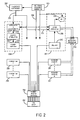
- the present invention employs a coil array 250 that includes a plurality of coil elements that can be separately driven by a plurality of RF transmitters to produce the prescribed radiofrequency (“RF”) field of excitation (“FOX”).
- RF radiofrequency
- the same coil array 250 can also be used with a plurality of receive channels, or in the alternative, the whole body RF coil 134 or a local RF coil can be used to acquire the MR signals.
- Many different coil array structures 250 may be used with the present invention, which maps the B 1 + RF excitation field produced by each coil array element.
- the RF system 126 includes a set of transmitters 298 that each produce a prescribed RF excitation field.
- the base, or carrier, frequency of this RF excitation field is produced under control of a frequency synthesizer 200 which receives a set of digital signals from the pulse sequence server 118 . These digital signals indicate the frequency and phase of the RF carrier signal produced at an output 201 .
- the RF carrier is applied to a modulator and up converter 202 in each transmitter 298 where its amplitude is modulated in response to a signal also received from the pulse sequence server 118 .
- the signal defines the envelope of the RF excitation pulse to be produced and is produced by sequentially reading out a series of stored digital values. These stored digital values may, be changed to enable any desired RF pulse envelope to be produced by each transmitter 298 .
- the magnitude of the RF excitation pulse produced at output 205 is attenuated by an exciter attenuator circuit 206 in each transmitter 298 which receives a digital command from the pulse sequence server 118 .
- the attenuated RF excitation pulses are applied to a power amplifier 251 in each transmitter 298 .
- the power amplifiers are current source devices that connect to respective transmit inputs on a set of transmit/receive switches 254 .
- N transmitters 298 are employed and connected through N transmit/receive switches 254 to N coil elements in an RF coil array 250 .
- the signal produced by the subject is picked up by the coil array 250 and applied to the inputs of a set of receive channels 257 .
- a pre-amplifier 253 in each receiver channel 257 amplifies the signal by an amount determined by a digital attenuation signal received from the pulse sequence server 118 .
- the received signal is at or around the Larmor frequency, and this high frequency signal is down converted in a two step process by a down converter 208 which first mixes the NMR signal with the carrier signal on line 201 and then mixes the resulting difference signal with a reference signal on line 204 .
- the down converter NMR signal is applied to the input of an analog-to-digital (A/D) converter 209 which samples and digitizes the analog signal and applies it to a digital detector and signal processor 210 which produces 16-bit in-phase (I) values and 16-bit quadrature (Q) values corresponding to the received signal.
- A/D analog-to-digital
- the resulting stream of digitized I and Q values of the received signal are output to the data acquisition server 120 .
- the reference signal as well as the sampling signal applied to the A/D converter 209 are produced by a reference frequency generator 203 .
- the transmit/receive switches 254 are operated by the pulse sequence server 118 to connect the N transmitters 298 to the N coil elements in the coil array 250 during those parts of the pulse sequence in which an RF field is to be produced.
- Each transmitter 298 is separately controlled by the pulse sequence server 118 to produce an RF field of a prescribed amplitude, frequency, phase and envelope at each of the N coil elements.
- the combined RF fields of the N coil elements produce the prescribed B 1 field throughout the region of interest in the subject during the imaging phase of the procedure.
- the pulse sequence server 118 operates the transmit/receive switches 254 to connect each of the N receive channels 257 to the respective N coil elements. Signals produced by excited spins in the subject are picked up and separately processed as described above.
- FIG. 3 a modified gradient-recalled echo (“GRE”) pulse sequence is shown that is employed to practice the present invention.
- the GRE pulse sequence is appended with a reset module that acts to saturate the spins.
- the GRE portion of the pulse sequence begins with the application of a RF excitation pulse 300 in the presence of a slice selective gradient 302 .
- the amplitude and duration of the RF excitation pulse 300 are chosen such that a desired flip angle, ⁇ , is enforced upon the excited spins.
- a rephasing lobe 304 is applied after the slice selective gradient 302 .
- Phase encoding is then performed through the application of a phase encoding gradient 306 .
- phase encoding gradient pulse is determined by the integral of its amplitude over its duration (i.e., its area). In most pulse sequences the duration is kept constant and the phase encoding pulse magnitude is stepped through its value by changing its amplitude.
- a dephasing gradient 308 is applied in the frequency encoding direction prior to readout. This causes the spins lying in the transverse plane to dephase such that when the readout gradient 310 is applied, they rephase and form a detectable free-induction decay signal.
- a B 1 -independent rotation (“BIR”) adiabatic excitation pulse 312 is then applied to saturate the remaining longitudinal magnetization in the transverse plane.
- a BIR-4 adiabatic pulse is employed.
- other pulses may be employed to saturate the magnetization, such as a composite pulse train.
- the BIR-4 pulse 312 is employed because of its insensitivity to B 1 + field inhomogeneities. Dephasing of the transverse magnetization then occurs through the application of a spoiler gradient 314 .
- an echo-planar imaging (“EPI”) pulse sequence may be employed.
- the image intensity of an image acquired with a GRE pulse sequence that employs an RF excitation pulse with flip angle, ⁇ is given by:
- I ⁇ ( r _ ) K ⁇ ⁇ ⁇ ⁇ ( r _ ) ⁇ ( 1 - e - TR / T 1 ⁇ ( r _ ) ) ⁇ sin ⁇ ⁇ ⁇ 1 - e - TR / T 1 ⁇ ( r _ ) ⁇ cos ⁇ ⁇ ⁇ ; Eqn . ⁇ ( 3 )
- I(V, r ) is the image intensity
- K is a proportionality constant
- ⁇ ( r ) is a spin density
- TR is the sequence repetition time
- T 1 ( r ) is the longitudinal relaxation time constant
- ⁇ is the flip angle
- r is a spatial position.
- I ⁇ ( V , r _ ) ⁇ ⁇ ( r _ ) ⁇ RX ⁇ ( r _ ) ⁇ ( 1 - e - TR / T 1 ⁇ ( r _ ) ) ⁇ sin ⁇ ⁇ ⁇ ⁇ ( V , r _ ) 1 - e - TR / T 1 ⁇ ( r _ ) ⁇ cos ⁇ ⁇ ⁇ ⁇ ( V , r _ ) ; Eqn . ⁇ ( 4 )
- RX( r ) is the receive coil profile and V is the applied transmit voltage.
- V is the applied transmit voltage.
- ⁇ ⁇ ( V , r _ ) ⁇ ⁇ TX ⁇ ( r _ ) ⁇ V ⁇ ⁇ 0 T ⁇ RF ⁇ ( t ) ⁇ ⁇ d t ; Eqn . ⁇ ( 5 )
- TSR is the saturation recovery time, which is the time that passes between the application of the spoiler gradient 314 and the next RF excitation 300 , demarcating the subsequent repetition of the pulse sequence.
- the transmit, B 1 + , and receive, B 1 ⁇ magnetic patterns are of opposite circular polarizations and are different at high B 0 fields, the use of a quantitative coil profile mapping technique is required to obtain the coil array reception profile.
- B 1 + maps of multiple transmit coils can be produced in less time than provided by previous methods.
- the present invention employs a synthesized coil array reception profile, B 1 ⁇ , to hasten the B 1 + mapping process. Throughout the process, the synthesized reception profile, B 1 ⁇ , from the same receiver coil combination is used.
- a coil having a uniform receive profile is employed; however, this is difficult to achieve at higher magnetic field strengths.
- a receive coil is operated such that the reception mode of the coil does not exhibit a signal null spot.
- the uniform reception mode (“mode-1”) satisfies this condition and is therefore preferably employed by the present invention.
- other types of coil array can be employed and driven in a manner that produced a reception profile having substantially no null spots.
- an embodiment of the B 1 + mapping process of the present invention begins generally by first estimating a reception profile in steps 400 - 416 . This estimated reception profile is subsequently employed to perform a rapid B 1 + profile mapping of all of the transmission coil elements (or modes of the RF transmission coil) in steps 418 - 424 . To this end, a B 1 + transmission mode of the coil array is first synthesized, as indicated at step 400 . More specifically, a B 1 + transmission mode having a low dynamic range is synthesized, such that only a small number of B 1 + transmission voltages need be employed when mapping a flip angle estimate map. Then, the imaging pulse sequence described above, with reference to FIG.
- Image data is acquired from the resulting MR signals, as indicated at step 404 .
- a loop is then entered into at 406 , in which additional image data is acquired by selecting a different transmission voltage at step 408 and repeating steps 402 and 404 .
- step 410 images are reconstructed from each of the acquired sets of image data.
- the number of transmission voltages employed is related to the uniformity of the B 1 + profile synthesized above in step 400 .
- a more uniform synthesized B 1 + profile requires a fewer number of transmission voltages. The reasoning for this can be explained as follows.
- the transmission voltages are, in effect, different sampling points of a sinusoidal relationship between the image intensity values of the images reconstructed in step 410 and the flip angle resulting from an RF excitation pulse applied at the selected transmission voltage using the synthesized B 1 + profile.
- the range of values selected for the transmission voltages relates to the average amplitude of the synthesized B 1 + profile. For example, it is be desirable to employ a set of transmission voltages having a lower range of values for a B 1 + profile having a higher average amplitude. The maximum transmission voltage value is therefore selected such that the range of transmission voltages adequately and accurately sample this sinusoidal relationship.
- the density-weighted reception profile, ⁇ ( r ) ⁇ RX( r ), can be determined, as indicated in step 416 . This is done simply by dividing the low-flip-angle image by the sine of the flip angle map produced in step 412 . Having now determined the density-weighted reception profile of the coil array, an estimation of the individual coil transmission profiles can be performed.
- a low-flip-angle image is produced for an individual transmit coil, as indicated in step 418 .
- a loop is entered at decision block 420 in which a low-flip-angle image is produced for each transmit coil in the coil array; each subsequent coil being selected in step 422 .
- a low-flip-angle image can be produced for a plurality of individual transmit modes.
- the B 1 + map for each transmission coil is then estimated, as indicated at step 424 .
- a flip angle map is produced for each coil by rearranging Eqn. (7) as follows:
- ⁇ ⁇ ( V , r _ ) sin - 1 ⁇ ( I ⁇ ( V , r _ ) ⁇ ⁇ ( r _ ) ⁇ RX ⁇ ( r _ ) ) ; Eqn . ⁇ ( 8 )
- the low-flip-angle image, I(V, r ), for each coil is divided by the density-weighted reception profile, ⁇ ( r ) ⁇ RX( r ), and the inverse sine of the result is calculated.
- the B 1 + map for each transmission coil is then calculated.
- Eqn. (5) can be rearranged as:
- TX ⁇ ( r _ ) ⁇ ⁇ ( V , r _ ) ⁇ ⁇ V ⁇ ⁇ 0 T ⁇ RF ⁇ ( t ) ⁇ ⁇ d t . Eqn . ⁇ ( 9 )
- This B 1 + map is indicative of the transmission characteristic of the particular RF coil. Specifically, the B 1 + map indicated the spatial sensitivity of the RF coil when operating to transmit RF energy.
Abstract
Description
M=√{square root over (I2 +Q 2)} Eqn. (1);
I(V,
I(V,
Claims (12)
Priority Applications (1)
| Application Number | Priority Date | Filing Date | Title |
|---|---|---|---|
| US12/422,017 US8076939B2 (en) | 2008-04-10 | 2009-04-10 | Method for fast magnetic resonance radiofrequency coil transmission profile mapping |
Applications Claiming Priority (2)
| Application Number | Priority Date | Filing Date | Title |
|---|---|---|---|
| US4377608P | 2008-04-10 | 2008-04-10 | |
| US12/422,017 US8076939B2 (en) | 2008-04-10 | 2009-04-10 | Method for fast magnetic resonance radiofrequency coil transmission profile mapping |
Publications (2)
| Publication Number | Publication Date |
|---|---|
| US20100066361A1 US20100066361A1 (en) | 2010-03-18 |
| US8076939B2 true US8076939B2 (en) | 2011-12-13 |
Family
ID=42006650
Family Applications (1)
| Application Number | Title | Priority Date | Filing Date |
|---|---|---|---|
| US12/422,017 Active 2029-11-27 US8076939B2 (en) | 2008-04-10 | 2009-04-10 | Method for fast magnetic resonance radiofrequency coil transmission profile mapping |
Country Status (1)
| Country | Link |
|---|---|
| US (1) | US8076939B2 (en) |
Cited By (7)
| Publication number | Priority date | Publication date | Assignee | Title |
|---|---|---|---|---|
| US9069998B2 (en) | 2012-10-15 | 2015-06-30 | General Electric Company | Determining electrical properties of tissue using magnetic resonance imaging and least squared estimate |
| US9513354B2 (en) | 2012-10-15 | 2016-12-06 | General Electric Company | Determining electrical properties of tissue using complex magnetic resonance images |
| US10422841B2 (en) * | 2016-04-21 | 2019-09-24 | Regents Of The University Of Minnesota | Systems and methods for designing multidimensional selective adiabatic pulses |
| US10527697B2 (en) * | 2017-07-05 | 2020-01-07 | Siemens Healthcare Gmbh | Method and imaging apparatus for optimizing a signal-to-noise ratio of a magnetic resonance image |
| US10768252B2 (en) * | 2018-10-24 | 2020-09-08 | General Electric Company | Methods and systems for sampling k-space data in magnetic resonance imaging |
| US10890631B2 (en) | 2017-01-19 | 2021-01-12 | Ohio State Innovation Foundation | Estimating absolute phase of radio frequency fields of transmit and receive coils in a magnetic resonance |
| US11047935B2 (en) | 2015-05-14 | 2021-06-29 | Ohio State Innovation Foundation | Systems and methods for estimating complex B1+ fields of transmit coils of a magnetic resonance imaging (MRI) system |
Families Citing this family (5)
| Publication number | Priority date | Publication date | Assignee | Title |
|---|---|---|---|---|
| WO2007124245A1 (en) * | 2006-04-21 | 2007-11-01 | Koninklijke Philips Electronics, N.V. | Magnetic resonance with time sequential spin excitation |
| US8085046B2 (en) * | 2008-08-28 | 2011-12-27 | The General Hospital Corporation | Coil array mode compression for parallel transmission magnetic resonance imaging |
| DE102010029463B4 (en) * | 2010-05-28 | 2014-07-24 | Siemens Aktiengesellschaft | Monitoring method for monitoring and / or protection of components, in particular a high-frequency antenna of a magnetic resonance system, as well as a monitoring device and a magnetic resonance system with a monitoring device for this purpose |
| DE102013205785B4 (en) * | 2013-04-02 | 2014-10-09 | Siemens Aktiengesellschaft | Determining a magnetic resonance system drive sequence based on a reduced number of field distribution cards |
| EP3901648A1 (en) * | 2020-04-24 | 2021-10-27 | Siemens Healthcare GmbH | Method and device for controlling a magnetic resonance imaging system |
Citations (11)
| Publication number | Priority date | Publication date | Assignee | Title |
|---|---|---|---|---|
| US5001428A (en) * | 1989-08-21 | 1991-03-19 | General Electric Company | Method for mapping the RF transmit and receive field in an NMR system |
| US5617028A (en) * | 1995-03-09 | 1997-04-01 | Board Of Trustees Of The Leland Stanford Junior University | Magnetic field inhomogeneity correction in MRI using estimated linear magnetic field map |
| US20030038632A1 (en) * | 2001-06-18 | 2003-02-27 | Duensing G. Randy | Method and apparatus for enhanced multiple coil imaging |
| US20030201775A1 (en) * | 2002-04-26 | 2003-10-30 | Boskamp Eddy Benjamin | Degenerate birdcage resonator for magnetic resonance imaging |
| US20040070394A1 (en) * | 2001-01-19 | 2004-04-15 | Gonzalez Ballester Miguel Angel | Parallel mr imaging using high-precision coil sensitivity map |
| US20050110488A1 (en) * | 2003-11-26 | 2005-05-26 | Yudong Zhu | Method and apparatus to generate an RF excitation consistent with a desired excitation profile using a transmit coil array |
| US6965232B2 (en) * | 2000-03-14 | 2005-11-15 | Beth Israel Deaconess Medical Center, Inc. | Parallel magnetic resonance imaging techniques using radiofrequency coil arrays |
| US6975114B1 (en) * | 2002-11-20 | 2005-12-13 | Nova Medical, Inc. | Methods for transmit excitation in magnetic resonance imaging using a transmit pulse with time varying spatial characteristics |
| US7336074B2 (en) * | 2006-05-05 | 2008-02-26 | Quality Electrodynamics | Active decoupling of MRI RF transmit coils |
| US20080100292A1 (en) * | 2006-10-30 | 2008-05-01 | Ileana Hancu | System and method for fast mr coil sensitivity mapping |
| US20080129294A1 (en) * | 2005-01-24 | 2008-06-05 | Koninklijke Philips Electronics N.V. | Orthogonal Coil for Magnetic Resonance Imaging |
-
2009
- 2009-04-10 US US12/422,017 patent/US8076939B2/en active Active
Patent Citations (11)
| Publication number | Priority date | Publication date | Assignee | Title |
|---|---|---|---|---|
| US5001428A (en) * | 1989-08-21 | 1991-03-19 | General Electric Company | Method for mapping the RF transmit and receive field in an NMR system |
| US5617028A (en) * | 1995-03-09 | 1997-04-01 | Board Of Trustees Of The Leland Stanford Junior University | Magnetic field inhomogeneity correction in MRI using estimated linear magnetic field map |
| US6965232B2 (en) * | 2000-03-14 | 2005-11-15 | Beth Israel Deaconess Medical Center, Inc. | Parallel magnetic resonance imaging techniques using radiofrequency coil arrays |
| US20040070394A1 (en) * | 2001-01-19 | 2004-04-15 | Gonzalez Ballester Miguel Angel | Parallel mr imaging using high-precision coil sensitivity map |
| US20030038632A1 (en) * | 2001-06-18 | 2003-02-27 | Duensing G. Randy | Method and apparatus for enhanced multiple coil imaging |
| US20030201775A1 (en) * | 2002-04-26 | 2003-10-30 | Boskamp Eddy Benjamin | Degenerate birdcage resonator for magnetic resonance imaging |
| US6975114B1 (en) * | 2002-11-20 | 2005-12-13 | Nova Medical, Inc. | Methods for transmit excitation in magnetic resonance imaging using a transmit pulse with time varying spatial characteristics |
| US20050110488A1 (en) * | 2003-11-26 | 2005-05-26 | Yudong Zhu | Method and apparatus to generate an RF excitation consistent with a desired excitation profile using a transmit coil array |
| US20080129294A1 (en) * | 2005-01-24 | 2008-06-05 | Koninklijke Philips Electronics N.V. | Orthogonal Coil for Magnetic Resonance Imaging |
| US7336074B2 (en) * | 2006-05-05 | 2008-02-26 | Quality Electrodynamics | Active decoupling of MRI RF transmit coils |
| US20080100292A1 (en) * | 2006-10-30 | 2008-05-01 | Ileana Hancu | System and method for fast mr coil sensitivity mapping |
Non-Patent Citations (20)
| Title |
|---|
| Alagappan et al, Degenerate Mode Band-Pass Birdcage Coil for Accelerated Parallel Excitation, Magnetic Resonance in Medicine 57:1148-1158 (2007). |
| Cunningham et al, Saturated Double-Angle Method for Rapid B1+ Mapping, Magnetic Resonance in Medicine 55:1326-1333 (2006). |
| Grissom et al, Spatial Domain Method for the Design of RF Pulses in Multicoil Parallel Excitation, Magnetic Resonance In Medicine 56:620-629 (2006). |
| Griswold et al, Autocalibrated accelerated Parallel Excitation (Transmit-GRAPPA), Proc. Intl. Soc. Mag. Reson. Med. 13 (2005), p. 2435. |
| Haacke et al., Magnetic Resonance Imaging: Physical Principles and Sequence Design, John Wiley & Sons, Inc. (1999). * |
| James Tropp, Reciprocity and Gyrotropism in Magnetic Resonance Transduction, Physical Review A 74, 062103 (2006). |
| Katscher et al, Transmit SENSE, Magnetic Resonance in Medicine 49:144-150 (2003). |
| Katscher et al., Transmit SENSE, Magnetic Resonance in Medicine 49:144-150 (2003). * |
| Kerr et al., Accelerated B1 mapping for parallel excitation, Proceedings of the 15th Annual Meeting of ISMRM, Berlin, Germany (2007). * |
| Meyer et al, Simultaneous Spatial and Spectral Selective Excitation, Magnetic Resonance in Medicine 15, 287-304 (1990). |
| Morrell et al, Three-Dimensional Spectral-Spatial Excitation, MRM 37:378-386 (1997). |
| Pauly et al, A k-Space Analysis of Small-Tip-Angle Excitation, Journal of Magnetic Resonance 81, 43-56 (1989). |
| Setsompop et al, in vivo Parallel RF Excitation with B0 Correction, Proc. Intl. Soc. Mag. Reson. Med. 15 (2007), p. 671. |
| Setsompop et al, Magnitude Least Squares Optimization for Parallel Radio Frequency Excitation Design Demonstrated at 7 Tesla With Eight Channels, Magnetic Resonance in Medicine 59:908-915 (2008). |
| Setsompop et al, Parallel RF Transmission with Eight Channels at 3 Tesla, Magnetic Resonance in Medicine 56:1163-1171 (2006). |
| Ullmann et al, Experimental Analysis of Parallel Excitation Using Dedicated Coil Setups and Simultaneous RF Transmission on Multiple Channels, Magnetic Resonance in Medicine 54:994-1001 (2005). |
| Vernickel et al, Eight Channel Transmit/Receive Body MRI Coil at 3T, MRM 58:381-389 (2007). |
| Xu et al, A Noniterative Method to Design Large-Tip-Angle Multidimensional Spatially-Selective Radio Frequency Pulses for Parallel Transmission, MRM 58:326-334 (2007). |
| Zhang et al, Reduction of Transmitter B1 Inhomogeneity With Transmit SENSE Slice-Select Pulses, Magnetic Resonance In Medicine 57:842-846 (2007). |
| Zhu, Parallel Excitation with an Array of Transmit Coils, Magnetic Resonance in Medicine 51:775-784 (2004). |
Cited By (7)
| Publication number | Priority date | Publication date | Assignee | Title |
|---|---|---|---|---|
| US9069998B2 (en) | 2012-10-15 | 2015-06-30 | General Electric Company | Determining electrical properties of tissue using magnetic resonance imaging and least squared estimate |
| US9513354B2 (en) | 2012-10-15 | 2016-12-06 | General Electric Company | Determining electrical properties of tissue using complex magnetic resonance images |
| US11047935B2 (en) | 2015-05-14 | 2021-06-29 | Ohio State Innovation Foundation | Systems and methods for estimating complex B1+ fields of transmit coils of a magnetic resonance imaging (MRI) system |
| US10422841B2 (en) * | 2016-04-21 | 2019-09-24 | Regents Of The University Of Minnesota | Systems and methods for designing multidimensional selective adiabatic pulses |
| US10890631B2 (en) | 2017-01-19 | 2021-01-12 | Ohio State Innovation Foundation | Estimating absolute phase of radio frequency fields of transmit and receive coils in a magnetic resonance |
| US10527697B2 (en) * | 2017-07-05 | 2020-01-07 | Siemens Healthcare Gmbh | Method and imaging apparatus for optimizing a signal-to-noise ratio of a magnetic resonance image |
| US10768252B2 (en) * | 2018-10-24 | 2020-09-08 | General Electric Company | Methods and systems for sampling k-space data in magnetic resonance imaging |
Also Published As
| Publication number | Publication date |
|---|---|
| US20100066361A1 (en) | 2010-03-18 |
Similar Documents
| Publication | Publication Date | Title |
|---|---|---|
| US8076939B2 (en) | Method for fast magnetic resonance radiofrequency coil transmission profile mapping | |
| US9778338B2 (en) | Method for simultaneous multi-slice magnetic resonance imaging | |
| US10139465B2 (en) | Method for magnetic resonance imaging with controlled aliasing | |
| US9778336B2 (en) | System and method for rapid, multi-shot segmented magnetic resonance imaging | |
| US9414766B2 (en) | Method for simultaneous multi-slice magnetic resonance imaging using single and multiple channel receiver coils | |
| US8278925B2 (en) | Method for relaxation-compensated fast multi-slice chemical exchange saturation transfer MRI | |
| US7397242B2 (en) | Parallel magnetic resonance imaging method using a radial acquisition trajectory | |
| US8154289B2 (en) | Method for joint sparsity-enforced k-space trajectory and radiofrequency pulse design | |
| US8148984B2 (en) | Method for magnitude constrained phase contrast magnetic resonance imaging | |
| US8400152B2 (en) | Method for k-space reconstruction in magnetic resonance inverse imaging | |
| US10004422B2 (en) | Method for measuring magnetization transfer between molecules with magnetic resonance imaging | |
| US5226418A (en) | Phase correction of complex - difference processed magnetic resonance angiograms | |
| US5212448A (en) | Nmr pulse sequence with burst rf excitation pulses having separately controlled phase | |
| US8698496B2 (en) | Method for two-dimensional correlation magnetic resonance spectroscopy | |
| US9689945B2 (en) | Virtual coil emulation in parallel transmission MRI | |
| US8274284B2 (en) | Parallel-accelerated complex subtraction MRI | |
| US8085046B2 (en) | Coil array mode compression for parallel transmission magnetic resonance imaging | |
| US5281916A (en) | NMR angiography using fast spin echo pulse sequences | |
| US5101156A (en) | Rapid flow measurement using an nmr imaging system | |
| US8334696B2 (en) | Method for magnetic resonance imaging with parallel and localized spatial encoding magnetic fields | |
| US8085044B2 (en) | Method for producing spectral-spatial parallel RF excitation pulses for magnetic resonance imaging | |
| US5093620A (en) | Encoding for nmr phase contrast flow measurement | |
| EP3640662A1 (en) | Magnetic resonance imaging using motion-compensated image reconstruction | |
| US8334694B2 (en) | System and method for embedded self-calibration within an inversion recovery pulse sequence | |
| US20220155396A1 (en) | Parallel mr imaging using wave-encoding |
Legal Events
| Date | Code | Title | Description |
|---|---|---|---|
| AS | Assignment |
Owner name: NATIONAL INSTITUTES OF HEALTH (NIH), U.S. DEPT. OF Free format text: CONFIRMATORY LICENSE;ASSIGNOR:THE GENERAL HOSPITAL CORPORATION;REEL/FRAME:023815/0668 Effective date: 20100119 |
|
| STCF | Information on status: patent grant |
Free format text: PATENTED CASE |
|
| CC | Certificate of correction | ||
| FEPP | Fee payment procedure |
Free format text: PAT HOLDER CLAIMS SMALL ENTITY STATUS, ENTITY STATUS SET TO SMALL (ORIGINAL EVENT CODE: LTOS); ENTITY STATUS OF PATENT OWNER: SMALL ENTITY |
|
| AS | Assignment |
Owner name: MASSACHUSETTS INSTITUTE OF TECHNOLOGY, MASSACHUSET Free format text: ASSIGNMENT OF ASSIGNORS INTEREST;ASSIGNORS:SETSOMPOP, KAWIN;ADALSTEINSSON, ELFAR;SIGNING DATES FROM 20090402 TO 20090602;REEL/FRAME:035687/0938 Owner name: THE GENERAL HOSPITAL CORPORATION, MASSACHUSETTS Free format text: ASSIGNMENT OF ASSIGNORS INTEREST;ASSIGNORS:ALAGAPPAN, VIJAYANAND;WALD, LAWRENCE;SIGNING DATES FROM 20090401 TO 20090402;REEL/FRAME:035687/0903 |
|
| FPAY | Fee payment |
Year of fee payment: 4 |
|
| MAFP | Maintenance fee payment |
Free format text: PAYMENT OF MAINTENANCE FEE, 8TH YR, SMALL ENTITY (ORIGINAL EVENT CODE: M2552); ENTITY STATUS OF PATENT OWNER: SMALL ENTITY Year of fee payment: 8 |
|
| MAFP | Maintenance fee payment |
Free format text: PAYMENT OF MAINTENANCE FEE, 12TH YR, SMALL ENTITY (ORIGINAL EVENT CODE: M2553); ENTITY STATUS OF PATENT OWNER: SMALL ENTITY Year of fee payment: 12 |