US8079683B2 - Inkjet printer cradle with shaped recess for receiving a printer cartridge - Google Patents
Inkjet printer cradle with shaped recess for receiving a printer cartridge Download PDFInfo
- Publication number
- US8079683B2 US8079683B2 US12/987,157 US98715711A US8079683B2 US 8079683 B2 US8079683 B2 US 8079683B2 US 98715711 A US98715711 A US 98715711A US 8079683 B2 US8079683 B2 US 8079683B2
- Authority
- US
- United States
- Prior art keywords
- cartridge
- ink
- printer
- cradle
- printhead
- Prior art date
- Legal status (The legal status is an assumption and is not a legal conclusion. Google has not performed a legal analysis and makes no representation as to the accuracy of the status listed.)
- Expired - Fee Related
Links
Images


Classifications
-
- B—PERFORMING OPERATIONS; TRANSPORTING
- B41—PRINTING; LINING MACHINES; TYPEWRITERS; STAMPS
- B41J—TYPEWRITERS; SELECTIVE PRINTING MECHANISMS, i.e. MECHANISMS PRINTING OTHERWISE THAN FROM A FORME; CORRECTION OF TYPOGRAPHICAL ERRORS
- B41J2/00—Typewriters or selective printing mechanisms characterised by the printing or marking process for which they are designed
- B41J2/005—Typewriters or selective printing mechanisms characterised by the printing or marking process for which they are designed characterised by bringing liquid or particles selectively into contact with a printing material
- B41J2/01—Ink jet
- B41J2/17—Ink jet characterised by ink handling
- B41J2/175—Ink supply systems ; Circuit parts therefor
- B41J2/17503—Ink cartridges
- B41J2/17543—Cartridge presence detection or type identification
- B41J2/1755—Cartridge presence detection or type identification mechanically
-
- B—PERFORMING OPERATIONS; TRANSPORTING
- B41—PRINTING; LINING MACHINES; TYPEWRITERS; STAMPS
- B41J—TYPEWRITERS; SELECTIVE PRINTING MECHANISMS, i.e. MECHANISMS PRINTING OTHERWISE THAN FROM A FORME; CORRECTION OF TYPOGRAPHICAL ERRORS
- B41J2/00—Typewriters or selective printing mechanisms characterised by the printing or marking process for which they are designed
- B41J2/005—Typewriters or selective printing mechanisms characterised by the printing or marking process for which they are designed characterised by bringing liquid or particles selectively into contact with a printing material
- B41J2/01—Ink jet
- B41J2/17—Ink jet characterised by ink handling
- B41J2/175—Ink supply systems ; Circuit parts therefor
- B41J2/17503—Ink cartridges
- B41J2/1752—Mounting within the printer
- B41J2/17523—Ink connection
Definitions
- the present invention relates to a printer system and in particular to a cradle unit for receiving a removable printer cartridge for an inkjet printer system.
- printheads that extend the entire width of the print media so that the printhead remains stationary as the print media progresses past.
- Such printheads are typically referred to as pagewidth printheads, and as the printhead does not move back and forth across the print media, much higher printing speeds are possible with this printhead than with traditionally traversing printheads.
- the printhead is the length of the print media, it must be supported within the structure of the printer unit and requires multiple electrical contacts to deliver power and data to drive the printhead, and as such removal and replacement of the printhead is not as easy as with traditional traversing printheads.
- an inkjet printer system including:
- the inkjet printer cartridges include pagewidth printheads and include an internal ink store in fluid communication with the pagewidth printhead.
- the internal ink store may include a number of individual ink storage reservoirs for separately storing ink for printing
- inkjet printer cartridges not supported by a particular inkjet printer cradle is formed with a protrusion, or an indentation, that interferes with an indentation, or a protrusion, of the particular inkjet printer cradle upon attempting to insert said cartridge into said cradle.
- indicia may be provided on the inkjet printer cartridges and on the inkjet printer cradles. Such indicia may be in the form of a coloured marker or the like.
- the present invention provides a printer system having a cradle unit that is adapted to receive a pagewidth printhead and associated printing fluid storage means in a cartridge form which can be readily removed and replaced from the printer cradle.
- the cradle unit is configured in a manner such that it is able to operate a number of removable inkjet cartridges having different performance characteristics to provide an inkjet printer that can readily be upgraded or downgraded depending upon the type of cartridge being used.
- the cradle of the present invention is also configured to prevent any inkjet printer cartridges that are not supported by the cradle from being used in the printer system, thereby ensuring the operational integrity of the system.
- FIG. 1 is a perspective view, showing front, top and right-hand sides of a printer cartridge according to a preferred embodiment of the present invention in combination with a printer cradle.
- FIG. 2 is a block diagram of the printer cartridge.
- FIG. 3 is a perspective view, showing front, top and right-hand sides of the printer cartridge prior to insertion into the printer cradle.
- FIG. 4 is a perspective view, showing rear, bottom and left-hand sides of the printer cartridge.
- FIG. 5 is a perspective view, showing, front, bottom and right-hand, sides of the printer cartridge in a partly dismantled state.
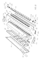
- FIG. 6 is a perspective view, showing front, bottom and right-hand sides of the printer cartridge in an exploded state.
- FIG. 7 is a plan view of the underside of a base molding of the cartridge revealing a number printing fluid conduits.
- FIG. 8 is a right-hand plan view of the printer cartridge.
- FIG. 9 is a cross-sectional view of the printer cartridge.
- FIG. 10 is a cross sectional view through a printhead chip nozzle in a first state of operation.
- FIG. 11 is a cross sectional view through the printhead chip nozzle in a second state of operation.
- FIG. 12 is a cross sectional view through a printhead chip nozzle subsequent to ejection of an ink droplet.
- FIG. 13 is a perspective, and partially cutaway, view of a printhead chip nozzle subsequent to ejection of an ink droplet.
- FIG. 14 is a perspective cross section of a printhead chip nozzle.
- FIG. 15 is a cross section of a printhead chip nozzle.
- FIG. 16 is a perspective and partially cutaway perspective view of a printhead chip nozzle.
- FIG. 17 is a plan view of a printhead chip nozzle.
- FIG. 18 is a plan, and partially cutaway view of a printhead chip nozzle.
- FIG. 19 is a perspective cross-sectioned view of a portion of a printhead chip.
- FIG. 20 is a block diagram of the printer cradle.
- FIG. 21 is a perspective, front, left-hand, upper side view of the printer cradle.
- FIG. 22 is a front plan view of the printer cradle.
- FIG. 23 is a top plan view of the printer cradle.
- FIG. 24 is a bottom plan view of the printer cradle.
- FIG. 25 is a right-hand plan view of the printer cradle.
- FIG. 26 is a perspective view of the left-hand, front and top sides of the printer cradle in an exploded state.
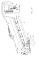
- FIG. 27 is a right-hand, and partially cutaway, plan view of the printer cradle.
- FIG. 28 is a perspective, rear left-hand and upper view of the printer cradle with print cartridge inserted.
- FIG. 29 is a perspective, rear left-hand and upper side view of the printer cradle with RFI shield removed.
- FIG. 30 is a perspective detail view of a portion of the left-hand side of the printer cradle.
- FIG. 31 is a perspective detail view of a portion of the right-hand side of the printer cradle.
- FIG. 32 is a perspective view of a single SoPEC chip controller board.
- FIG. 33 is a perspective view of a twin SoPEC chip controller board.
- FIG. 34 is a block diagram of a SoPEC chip.
- FIG. 35 is a perspective view of an ink refill cartridge in an emptied state.
- FIG. 36 is a perspective view of the ink refill cartridge in a full state.
- FIG. 37 is a perspective view of the ink refill cartridge in an exploded state.
- FIG. 38 is a cross section of the ink refill cartridge in an emptied state.
- FIG. 39 is a cross section of the ink refill cartridge in a full state.
- FIG. 40 depicts a full ink refill cartridge aligned for docking to a printer cartridge.
- FIG. 41 depicts the ink refill cartridge docked to a printer cartridge prior to dispensing ink.
- FIG. 42 depicts the ink refill cartridge docked to a printer cartridge subsequent to dispensing ink.
- FIG. 1 depicts an inkjet printer 2 which includes a cradle 4 that receives a replaceable print cartridge 6 into a recess formed in the cradle's body according to a preferred embodiment of the present invention.
- Cartridge 6 is secured in the cradle recess by a retainer in the form of latch 7 that is connected by a hinge to cradle 4 .
- Visible on the upper surface of print cartridge 6 is an ink refill port 8 which receives an ink refill cartridge during use.
- Cartridge 6 includes ink refill port 8 and an ink delivery assembly 10 for storing and delivering ink to a micro-electromechanical pagewidth print head chip 52 .
- Printhead chip 52 receives power and data signals from cradle 4 (see FIG. 1 ) via power and data interface 58 .
- a rotor element 60 which is mechanically driven by cradle 4 has three faces which respectively serve to: blot printhead chip 52 subsequent to ink ejection; seal the printhead when it is not in use; and act as a platen during printing.
- Cartridge 6 also includes an authentication device in the form of quality assurance chip 57 which contains various manufacturer codes that are read by electronic circuitry of controller board 82 of cradle during use. The manufacturer codes are read to verify the authenticity of cartridge 6 .
- structurally cartridge 6 has a body including a base molding 20 that houses a polyethylene membrane 26 including ink storage reservoirs in the form of pockets 28 , 30 , 32 , 34 for each of four different printing fluids.
- the printing fluids will be cyan, magenta, yellow and black inks
- Additional storage reservoirs may also be provided within base molding 20 in order to receive and store an ink fixative and/or an infrared ink as various applications may require. In this regard there may be up to six storage reservoirs provided with base molding 20 .
- membrane 26 As membrane 26 is filled with printing fluids it expands and conversely, as ink is consumed during printing the membrane collapses.
- Cover molding 36 includes a recess 38 that receives an ink inlet molding 24 having a number of passageways.
- a number of apertures 42 A- 42 E are formed through recess 38 and are arranged to communicate with corresponding passageways of ink inlet molding 24 .
- the passages of the ink inlet member convey ink from an externally fitted ink refill cartridge to each of the ink storage reservoirs via a series of ink delivery paths formed into ink membrane 26 .
- the ink delivery paths connect each aperture 42 A- 42 E of the ink inlet member 24 to its dedicated ink storage reservoir 28 - 34 .
- the ink is typically delivered under pressure thereby causing it to flow into and expand the reservoirs of membrane 26 .
- An ink inlet seal 40 is located over the outside of recess 38 in order to seal apertures 42 A- 42 E prior to use.
- Pagewidth printhead chip 52 is disposed along the outside of cartridge base molding 20 in the region below the ink storage reservoirs. As shown in FIG. 7 , a number of conduits 43 A- 43 E are formed in the underside of the cartridge base molding and are in direct communication with each of ink storage reservoirs 28 , 30 , 32 , 34 . The conduits provide an ink delivery path from the underside of cartridge base molding 20 to inlet ports provided in ink delivery moldings 48 onto which the printhead chip 52 is attached.
- ink delivery moldings 48 are preferably made from a plastic, such as LCP (Liquid Crystal Polymer) via an injection molding process and include a plurality of elongate conduits disposed along the length thereof arranged to distribute printing fluids from the reservoirs in membrane 26 to printhead chip 52 .
- Each of the elongate conduits are dedicated to carry a specific fluid, such as a particular color ink or a fixative and to allow the fluid to be distributed along the length of the printhead.
- an ink sealing strip 45 is placed between cartridge base molding 20 and ink delivery molding 48 .
- the ink sealing strip is formed with apertures that allow fluid transfer to occur between the two elements, however the strip acts to seal the channels formed in the cartridge base molding to prevent fluid leakage.
- an air distribution channel 50 that acts to distribute pressurized air from air inlet port 76 over the nozzles of printhead 52 .
- the air distribution channel runs along the length of printhead 52 and communicates with air inlet port 76 .
- a porous air filter 51 extends along the length of air distribution channel 50 and serves to remove dust and particulate matter that may be present in the air and which might otherwise contaminate printhead 52 .
- Porous air filter 51 has a selected porosity so that only air at a desired threshold pressure is able to pass through it, thereby ensuring that the air is evenly delivered at a constant pressure along the length of the printhead.
- channel 50 firstly fills with compressed air until it reaches the threshold pressure within the channel. Once the threshold pressure is reached the air is able to pass through porous air filter 51 evenly along the length of the filter. The filtered air is then directed over the printhead.
- the pressurized air is to prevent degradation of the printhead by keeping its nozzles free of dust and debris.
- the pressurized air is provided by an air compressor (item 122 of FIG. 13 ) incorporated into cradle 4 .
- An air nozzle (item 124 of FIG. 13 ) of the compressor pierces air seal 44 upon insertion of cartridge 6 into cradle 4 and mates with air inlet port 76 .
- An air coverplate 54 is fixed to the cartridge base molding and evenly distributes air across printhead 52 in the manner described above.
- Power and data signals are provided to printhead 52 by means of busbar 56 which is in turn coupled to external data and power connectors 58 A and 58 B.
- An authentication device in the form of a quality assurance (QA) chip 57 is mounted to connector 58 A.
- QA chip 57 Upon inserting print cartridge 6 into cradle 4 the data and power connectors 58 A and 58 B, and QA chip 57 , mate with corresponding connectors (items 84 A, 84 B of FIG. 3 ) on cradle 4 , thereby facilitating power and data communication between the cradle and the cartridge.
- QA chip 57 is tested in use by a portion of controller board 82 configured to act as a suitable verification circuit.
- Rotor element 60 is rotatably mounted adjacent and parallel to printhead 52 .
- the rotor element has three faces, as briefly explained previously, as follows: a platen face, which during printing acts as a support for print media and assists in bringing the print media close to printhead 52 ; a capping face for capping the printhead when not in use in order to reduce evaporation of printing fluids from the nozzles; and a blotter face, for blotting the printhead subsequent to a printing operation.
- the three faces of the rotor element are each separated by 120 degrees.
- axial pins 64 A and 64 B At opposite ends of rotor element 60 there extend axial pins 64 A and 64 B about which are fixed cogs 62 A and 62 B respectively. The free ends of axial pins 64 A and 64 B are received into slider blocks 66 A and 66 B. Slider blocks 66 A and 66 B include flanges 68 A and 68 B which are located within slots 70 A and 70 B of end plates 22 A and 22 B. The end plates are fixed at either end of cartridge base molding 20 .
- Slider blocks 66 A and 66 B are biased towards the printhead end of slots 70 A and 70 B by springs 72 A and 72 B held at either end by their insertion into blind holes in slider block 66 A and 66 B and by their seating over protrusions into slots 70 A and 70 B as best seen in FIG. 8 . Accordingly, rotor element 60 is normally biased so it is brought closely adjacent to printhead 52 .
- rotor element 60 is arranged so that its capping face caps printhead 52 in order to prevent the surrounding air from drying out the printhead's nozzles.
- FIG. 19 shows an array of the nozzle arrangements 801 formed on a silicon substrate 8015 .
- the nozzle arrangements are identical, but in the preferred embodiment, different nozzle arrangements are fed with different colored inks and fixative. It will be noted that rows of the nozzle arrangements 801 are staggered with respect to each other, allowing closer spacing of ink dots during printing than would be possible with a single row of nozzles. The multiple rows also allow for redundancy (if desired), thereby allowing for a predetermined failure rate per nozzle.
- Each nozzle arrangement 801 is the product of an integrated circuit fabrication technique.
- the nozzle arrangement 801 defines a micro-electromechanical system (MEMS).
- MEMS micro-electromechanical system
- the ink jet printhead chip 52 (see FIG. 6 ) includes a silicon wafer substrate 8015 . 0.35 Micron 1 P4M 12 volt CMOS microprocessing circuitry is positioned on the silicon wafer substrate 8015 .
- a silicon dioxide (or alternatively glass) layer 8017 is positioned on the wafer substrate 8015 .
- the silicon dioxide layer 8017 defines CMOS dielectric layers.
- CMOS top-level metal defines a pair of aligned aluminium electrode contact layers 8030 positioned on the silicon dioxide layer 8017 .
- Both the silicon wafer substrate 8015 and the silicon dioxide layer 8017 are etched to define an ink inlet channel 8014 having a generally circular cross section (in plan).
- An aluminium diffusion barrier 8028 of CMOS metal 1, CMOS metal 2/3 and CMOS top level metal is positioned in the silicon dioxide layer 8017 about the ink inlet channel 8014 .
- the diffusion barrier 8028 serves to inhibit the diffusion of hydroxyl ions through CMOS oxide layers of the drive circuitry layer 8017 .
- a passivation layer in the form of a layer of silicon nitride 8031 is positioned over the aluminium contact layers 8030 and the silicon dioxide layer 8017 .
- Each portion of the passivation layer 8031 positioned over the contact layers 8030 has an opening 8032 defined therein to provide access to the contacts 8030 .
- the nozzle arrangement 801 includes a nozzle chamber 8029 defined by an annular nozzle wall 8033 , which terminates at an upper end in a nozzle roof 805 and a radially inner nozzle rim 804 that is circular in plan.
- the ink inlet channel 8014 is in fluid communication with the nozzle chamber 8029 .
- a moving rim 8010 At a lower end of the nozzle wall, there is disposed a moving rim 8010 , that includes a moving seal lip 8040 .
- An encircling wall 8038 surrounds the movable nozzle, and includes a stationary seal lip 8039 that, when the nozzle is at rest as shown in FIG. 10 , is adjacent the moving rim 8010 .
- a fluidic seal 8011 is formed due to the surface tension of ink trapped between the stationary seal lip 8039 and the moving seal lip 8040 . This prevents leakage of ink from the chamber whilst providing a low resistance coupling between the encircling wall 8038 and the nozzle wall 8033 .
- a plurality of radially extending recesses 8035 is defined in the roof 805 about the nozzle rim 804 .
- the recesses 8035 serve to contain radial ink flow as a result of ink escaping past the nozzle rim 804 .
- the nozzle wall 8033 forms part of a lever arrangement that is mounted to a carrier 8036 having a generally U-shaped profile with a base 8037 attached to the layer 8031 of silicon nitride.
- the lever arrangement also includes a lever arm 8018 that extends from the nozzle walls and incorporates a lateral stiffening beam 8022 .
- the lever arm 8018 is attached to a pair of passive beams 806 , formed from titanium nitride (TiN) and positioned on either side of the nozzle arrangement, as best shown in FIGS. 13 and 18 .
- the other ends of the passive beams 806 are attached to the carrier 8036 .
- the lever arm 8018 is also attached to an actuator beam 807 , which is formed from TiN. It will be noted that this attachment to the actuator beam is made at a point a small but critical distance higher than the attachments to the passive beam 806 .
- the actuator beam 807 is substantially U-shaped in plan, defining a current path between the electrode 809 and an opposite electrode 8041 .
- Each of the electrodes 809 and 8041 are electrically connected to respective points in the contact layer 8030 .
- the actuator beam is also mechanically anchored to anchor 808 .
- the anchor 808 is configured to constrain motion of the actuator beam 807 to the left of FIGS. 10 to 12 when the nozzle arrangement is in operation.
- the TiN in the actuator beam 807 is conductive, but has a high enough electrical resistance that it undergoes self-heating when a current is passed between the electrodes 809 and 8041 . No current flows through the passive beams 806 , so they do not expand.
- the device at rest is filled with ink 8013 that defines a meniscus 803 under the influence of surface tension.
- the ink is retained in the chamber 8029 by the meniscus, and will not generally leak out in the absence of some other physical influence.
- a current is passed between the contacts 809 and 8041 , passing through the actuator beam 807 .
- the self-heating of the beam 807 due to its resistance causes the beam to expand.
- the dimensions and design of the actuator beam 807 mean that the majority of the expansion in a horizontal direction with respect to FIGS. 10 to 12 .
- the expansion is constrained to the left by the anchor 808 , so the end of the actuator beam 807 adjacent the lever arm 8018 is impelled to the right.
- the relative horizontal inflexibility of the passive beams 806 prevents them from allowing much horizontal movement the lever arm 8018 .
- the relative displacement of the attachment points of the passive beams and actuator beam respectively to the lever arm causes a twisting movement that causes the lever arm 8018 to move generally downwards.
- the movement is effectively a pivoting or hinging motion.
- the absence of a true pivot point means that the rotation is about a pivot region defined by bending of the passive beams 806 .
- the downward movement (and slight rotation) of the lever arm 8018 is amplified by the distance of the nozzle wall 8033 from the passive beams 806 .
- the downward movement of the nozzle walls and roof causes a pressure increase within the chamber 8029 , causing the meniscus to bulge as shown in FIG. 11 .
- the surface tension of the ink means the fluid seal 8011 is stretched by this motion without allowing ink to leak out.
- the drive current is stopped and the actuator beam 807 quickly cools and contracts.
- the contraction causes the lever arm to commence its return to the quiescent position, which in turn causes a reduction in pressure in the chamber 8029 .
- the interplay of the momentum of the bulging ink and its inherent surface tension, and the negative pressure caused by the upward movement of the nozzle chamber 8029 causes thinning, and ultimately snapping, of the bulging meniscus to define an ink drop 802 that continues upwards until it contacts adjacent print media.
- meniscus 803 forms the concave shape shown in FIG. 12 .
- Surface tension causes the pressure in the chamber 8029 to remain relatively low until ink has been sucked upwards through the inlet 8014 , which returns the nozzle arrangement and the ink to the quiescent situation shown in FIG. 10 .
- the nozzle arrangement also incorporates a test mechanism that can be used both post-manufacture and periodically after the printhead is installed.
- the test mechanism includes a pair of contacts 8020 that are connected to test circuitry (not shown).
- a bridging contact 8019 is provided on a finger 8080 that extends from the lever arm 8018 . Because the bridging contact 8019 is on the opposite side of the passive beams 806 , actuation of the nozzle causes the priding contact to move upwardly, into contact with the contacts 8020 .
- Test circuitry can be used to confirm that actuation causes this closing of the circuit formed by the contacts 8019 and 8020 . If the circuit closed appropriately, it can generally be assumed that the nozzle is operative.
- FIG. 20 is a functional block diagram of printer cradle 4 .
- the printer cradle is built around a controller board 82 that includes one or more custom Small Office Home Office Printer Engine Chips (SoPEC) whose architecture will be described in detail shortly.
- Controller board 82 is coupled to a USB port 130 for connection to an external computational device such as a personal computer or digital camera containing digital files for printing.
- Controller board 82 also monitors:
- a paper sensor 192 which detects the presence of print media
- printer cartridge chip interface 84 which in use couples to printer cartridge QA chip 57 (see FIG. 6 );
- an ink refill cartridge QA chip contact 132 which in use couples to an ink refill cartridge QA chip (visible as item 176 in FIG. 37 );
- rotor element angle sensor 149 which detects the orientation of rotor element 60 (see FIG. 6 ).
- controller board In use the controller board processes the data received from USB port 130 and from the various sensors described above and in response drives a motor 110 , tricolor indicator LED 135 and, via interface 84 , printhead chip 52 (see FIG. 6 ).
- motor 110 is mechanically coupled to drive a number of mechanisms that provide auxiliary services to print cartridge 6 (see FIG. 6 ).
- the driven mechanisms include:
- a rotor element drive assembly 145 for operating rotor element 60 (see FIG. 6 );
- print media transport assembly 93 which passes print media across printhead chip 52 during printing
- an air compressor 122 which provides compressed air to keep printhead chip 52 (see FIG. 6 ) clear of debris.
- motor 110 is coupled to each of the above mechanisms by a transmission assembly which includes a direct drive coupling from the motor spindle to an impeller of the air compressor and a worm-gear and cog transmission to the rotor element and print media transport assembly.
- cradle 4 has a body shaped to complement cartridge 6 so that when mated together they form an inkjet printer.
- the cradle body is formed of base molding 90 and cradle molding 80 .
- the base molding acts as a support base for the cradle and also locates drive motor 110 , rotor element roller 94 and drive roller 96 .
- the base molding is snap fastened to cradle molding 80 by means of a number of corresponding flanges 120 and slots 123 .
- Cradle molding 80 defines an elongate recess 89 dimensioned to locate print cartridge 6 .
- a number of indentations in the form of slots 86 are formed in an internal wall of the cradle for receiving complementary protrusions in the form of ribs 78 ( FIG. 4 ) of cartridge 6 . Consequently cartridge 6 must be correctly orientated in order for it to be fully received into cradle molding 80 . Furthermore, the slots ensures that only those cartridges that are supported by the electronics of the cradle, and hence have non-interfering ribs, can be inserted into the cradle, thereby overcoming the problem of the drive electronics of the cradle attempting to drive cartridges having unsupported performance characteristics. Controller 82 is arranged to determine the performance characteristics of cartridges inserted into cradle 4 and to operate each cartridge in response to the determined performance characteristics.
- an inkjet cradle to be provided with a starter cartridge having relatively basic performance characteristics and then to upgrade as desired by replacing the starter cartridge with an improved performance upgrade cartridge.
- the upgrade cartridge may be capable of a higher print rate or support more inks than the starter cartridge.
- drive shaft 127 of motor 110 terminates in a worm gear 129 that meshes with a cog 125 B that is, in turn, fixed to drive roller 96 .
- the drive roller is supported at either end by bearing mount assemblies 100 A and 100 B, which are in turn fixed into slots 101 A and 101 B of cradle mounting 80 (see also FIG. 30 ).
- rotor element translation roller 94 and pinch roller 98 are also supported by bearing mount assemblies 100 A and 100 B.
- the flipper gear assembly consists of a housing 144 which holds an inner gear 142 and an outer gear 143 that mesh with each other.
- the inner gear is fixed and coaxial with drive roller 96 whereas housing 144 is free to rotate about drive roller 96 .
- the housing rotates with drive roller 96 taking with it outer gear 143 until it either abuts a stopper located on the cradle base molding 90 or outer gear 143 meshes with rotor element drive cog 146 .
- the direction of rotation of drive roller 96 is dependent on the sense of the driving current applied to motor 110 by control board 82 (see FIG. 29 ).
- outer gear 143 with rotor element drive cog 146 forms rotor element drive assembly 145 comprising drive roller 96 , inner gear 142 , outer gear 143 and rotor element drive cog 146 . Consequently, in this configuration power can be transmitted from drive roller 96 to rotor element drive roller 94 .
- cams 148 A and 148 B which are located in corresponding cam followers 150 A and 150 B.
- Cam followers 150 A and 150 B are ring shaped and pivotally secured at one side by pivot pins 152 A and 152 B respectively.
- Hinged jaws 154 A and 154 B are provided for clutching the rotor element slider blocks (items 66 A, 66 B of FIG. 6 ) of the printer cartridge.
- the jaws are each pivotally connected to cam followers 150 A and 150 B opposite pins 152 A and 152 B respectively.
- cradle 4 includes a rotor element sensor unit 156 ( FIG. 20 ) to detect the actual orientation of the rotor element.
- Sensor unit 156 consists of a light source and a detector unit which detects the presence of reflected light.
- Rotor element 60 has a reflective surface that is arranged to reflect rays from the light source so that the orientation of the rotor element can be detected by sensor 156 .
- controller board 82 is able to determine which face of rotor element 60 is adjacent printhead 52 .
- motor 110 also drives an air compressor 122 that includes a fan housing 112 , air filter 116 and impeller 114 .
- Fan housing 112 includes an air outlet 124 that is adapted to mate with air inlet port 76 ( FIG. 6 ) of cartridge 6
- a metal backplane 92 is secured to the rear of cradle molding 80 as may be best seen in side view in FIG. 25 and in cross section in FIG. 27 .
- Mounted to backplane 92 is a control board 82 loaded with various electronic circuitry.
- the control board is covered by a metal radio frequency interference (RFI) shield 102 .
- Control board 82 is electrically coupled to cradle connectors 84 A and 84 B via a flex PCB connector 106 and also to an external data and power connection point in the form of USB port connector 130 .
- USB connector 130 enables connection to an external personal computer or other computational device.
- Cradle connectors 84 A, 84 B are supported in slots formed at either end of cradle molding 80 and are arranged so that upon printer cartridge 6 being fully inserted into recess 89 of the cradle molding, cradle connectors 84 A and 84 B make electrical contact with cartridge connectors 58 A and 58 B (see FIG. 6 ).
- Controller board 82 is connected by various cable looms and flexible PCB 106 to QA chip contact 132 .
- the QA chip contact is located in a recess 134 formed in cradle molding 80 and is situated so that during ink refilling it makes contact with a QA chip 176 located in an ink refill cartridge that will be described shortly.
- Controller board 82 also drives a tricolor indicator LED (item 135 of FIG. 20 ) which is optically coupled to a lightpipe 136 .
- the lightpipe terminates in an indicator port 138 formed in cradle molding 80 so that light from the tricolor indicator LED may be viewed from outside the casing.
- Printer units have a fundamental structure, namely a cradle assembly which contains all of the necessary electronics, power and paper handling requirements, and a cartridge unit that includes the highly specialised printhead and ink handling requirements of the system, such that it may be possible for a cradle unit to support a cartridge unit which enables different capabilities without the need to purchase a new cradle unit.
- cartridge units each having a number of different features may be provided.
- a cartridge unit of three distinct types in a simple form it may be possible to provide a cartridge unit of three distinct types:
- Cartridge units of different functionality may bear indicia such as color coded markings so that their compatibility with the cradle units can be easily identified.
- FIG. 32 shows the main PCB unit for a cradle unit operating at 15-30 ppm
- FIG. 33 shows a main PCB unit for driving a cartridge unit operating at 60 ppm.
- the PCBs are almost identical with the main difference being the presence of 2 SoPEC chips on the 60 ppm PCB.
- the printer preferably also includes one or more system on a chip (SoC) components, as well as the print engine pipeline control application specific logic, configured to perform some or all of the functions described above in relation to the printing pipeline.
- SoC system on a chip
- SoPEC device consists of 3 distinct subsystems: a Central Processing Unit (CPU) subsystem 301 , a Dynamic Random Access Memory (DRAM) subsystem 302 and a Print Engine Pipeline (PEP) subsystem 303 .
- CPU Central Processing Unit
- DRAM Dynamic Random Access Memory
- PEP Print Engine Pipeline
- the CPU subsystem 301 includes a CPU 30 that controls and configures all aspects of the other subsystems. It provides general support for interfacing and synchronizing the external printer with the internal print engine. It also controls the low-speed communication to QA chips (which are described elsewhere in this specification).
- the CPU subsystem 301 also contains various peripherals to aid the CPU, such as General Purpose Input Output (GPIO, which includes motor control), an Interrupt Controller Unit (ICU), LSS Master and general timers.
- GPIO General Purpose Input Output
- ICU Interrupt Controller Unit
- LSS Master General Timers.
- SBC Serial Communications Block
- the Serial Communications Block (SCB) on the CPU subsystem provides a full speed USB1.1 interface to the host as well as an Inter SoPEC Interface (ISI) to other SoPEC devices (not shown).
- ISI Inter SoPEC Interface
- the DRAM subsystem 302 accepts requests from the CPU, Serial Communications Block (SCB) and blocks within the PEP subsystem.
- the DRAM subsystem 302 and in particular the DRAM Interface Unit (DIU), arbitrates the various requests and determines which request should win access to the DRAM.
- the DIU arbitrates based on configured parameters, to allow sufficient access to DRAM for all requestors.
- the DIU also hides the implementation specifics of the DRAM such as page size, number of banks and refresh rates.
- the Print Engine Pipeline (PEP) subsystem 303 accepts compressed pages from DRAM and renders them to bi-level dots for a given print line destined for a printhead interface that communicates directly with up to 2 segments of a bi-lithic printhead.
- the first stage of the page expansion pipeline is the Contone Decoder Unit (CDU), Lossless Bi-level Decoder (LBD) and Tag Encoder (TE).
- the CDU expands the JPEG-compressed contone (typically CMYK) layers
- the LBD expands the compressed bi-level layer (typically K)
- the TE encodes Netpage tags for later rendering (typically in IR or K ink).
- the output from the first stage is a set of buffers: the Contone FIFO unit (CFU), the Spot FIFO Unit (SFU), and the Tag FIFO Unit (TFU).
- the CFU and SFU buffers are implemented in DRAM.
- the second stage is the Halftone Compositor Unit (HCU), which dithers the contone layer and composites position tags and the bi-level spot layer over the resulting bi-level dithered layer.
- HCU Halftone Compositor Unit
- a number of compositing options can be implemented, depending upon the printhead with which the SoPEC device is used. Up to 6 channels of bi-level data are produced from this stage, although not all channels may be present on the printhead.
- the printhead may be CMY only, with K pushed into the CMY channels and IR ignored.
- the encoded tags may be printed in K if IR ink is not available (or for testing purposes).
- a Dead Nozzle Compensator compensates for dead nozzles in the printhead by color redundancy and error diffusing of dead nozzle data into surrounding dots.
- the resultant bi-level 6 channel dot-data (typically CMYK, Infrared, Fixative) is buffered and written to a set of line buffers stored in DRAM via a Dotline Writer Unit (DWU).
- CMYK Infrared, Fixative
- DWU Dotline Writer Unit
- the dot-data is loaded back from DRAM, and passed to the printhead interface via a dot FIFO.
- the dot FIFO accepts data from a Line Loader Unit (LLU) at the system clock rate (pclk), while the PrintHead Interface (PHI) removes data from the FIFO and sends it to the printhead at a rate of 2 ⁇ 3 times the system clock rate.
- LLU Line Loader Unit
- PHI PrintHead Interface
- the DRAM is 2.5 Mbytes in size, of which about 2 Mbytes are available for compressed page store data.
- a compressed page is received in two or more bands, with a number of bands stored in memory.
- a band of the page is consumed by the PEP subsystem 303 for printing, a new band can be downloaded.
- the new band may be for the current page or the next page.
- the embedded USB 1.1 device accepts compressed page data and control commands from the host PC, and facilitates the data transfer to either the DRAM (or to another SoPEC device in multi-SoPEC systems, as described below).
- SoPEC devices can be used in alternative embodiments, and can perform different functions depending upon the particular implementation. For example, in some cases a SoPEC device can be used simply for its onboard DRAM, while another SoPEC device attends to the various decompression and formatting functions described above. This can reduce the chance of buffer under-run, which can happen in the event that the printer commences printing a page prior to all the data for that page being received and the rest of the data is not received in time. Adding an extra SoPEC device for its memory buffering capabilities doubles the amount of data that can be buffered, even if none of the other capabilities of the additional chip are utilized.
- Each SoPEC system can have several quality assurance (QA) devices designed to cooperate with each other to ensure the quality of the printer mechanics, the quality of the ink supply so the printhead nozzles will not be damaged during prints, and the quality of the software to ensure printheads and mechanics are not damaged.
- QA quality assurance
- each printing SoPEC will have an associated printer QA, which stores information printer attributes such as maximum print speed.
- An ink cartridge for use with the system will also contain an ink QA chip, which stores cartridge information such as the amount of ink remaining
- the printhead also has a QA chip, configured to act as a ROM (effectively as an EEPROM) that stores printhead-specific information such as dead nozzle mapping and printhead characteristics.
- the CPU in the SoPEC device can optionally load and run program code from a QA Chip that effectively acts as a serial EEPROM.
- the CPU in the SoPEC device runs a logical QA chip (ie, a software QA chip).
- Each SoPEC device has two LSS system buses that can communicate with QA devices for system authentication and ink usage accounting.
- a large number of QA devices can be used per bus and their position in the system is unrestricted with the exception that printer QA and ink QA devices should be on separate LSS busses.
- the logical QA communicates with the ink QA to determine remaining ink.
- the reply from the ink QA is authenticated with reference to the printer QA.
- the verification from the printer QA is itself authenticated by the logical QA, thereby indirectly adding an additional authentication level to the reply from the ink QA.
- HMAC-SHA1 authentication is used for data
- RSA is used for program code, although other schemes could be used instead.
- a single SoPEC device can control two bi-lithic printheads and up to six color channels.
- Six channels of colored ink are the expected maximum in a consumer SOHO, or office bi-lithic printing environment, and include:
- the bi-lithic printer is capable of printing so fast, a fixative may be required to enable the ink to dry before the page touches the page already printed. Otherwise ink may bleed between pages. In relatively low-speed printing environments the fixative may not be required.
- the SoPEC device is color space agnostic. Although it can accept contone data as CMYX or RGBX, where X is an optional 4th channel, it also can accept contone data in any print color space. Additionally, SoPEC provides a mechanism for arbitrary mapping of input channels to output channels, including combining dots for ink optimization and generation of channels based on any number of other channels. However, inputs are typically CMYK for contone input, K for the bi-level input, and the optional Netpage tag dots are typically rendered to an infrared layer. A fixative channel is typically generated for fast printing applications.
- the SoPEC device is also resolution agnostic. It merely provides a mapping between input resolutions and output resolutions by means of scale factors.
- the expected output resolution for the preferred embodiment is 1600 dpi, but SoPEC actually has no knowledge of the physical resolution of the Bi-lithic printhead.
- the SoPEC device is page-length agnostic. Successive pages are typically split into bands and downloaded into the page store as each band of information is consumed.
- DRAM DIU DRAM Provides interface for DRAM interface read and write access for the unit various SoPEC units, CPU and the SCB block.
- the DIU provides arbitration between competing units and controls DRAM access.
- DRAM CPU CPU Central CPU for system configuration Processing and control.
- Unit MMU Memory Limits access to certain memory Management address areas in CPU user mode.
- Unit RDU Real-time Facilitates the observation of the Debug Unit contents of most of the CPU addressable registers in SoPEC, in addition to some pseudo- registers in real time.
- TIM General Contains watchdog and general Timer system timers.
- LSS Low Speed Low level controller for Serial interfacing with the QA chips Interfaces GPIO General General IO controller, with Purpose built-in Motor control unit, LED IOs pulse units and de-glitch circuitry ROM Boot ROM 16 KBytes of System Boot ROM code ICU Interrupt General Purpose interrupt Control- controller with configurable ler Unit priority, and masking.
- cation Block Print PCU PEP Provides external CPU with the Engine controller means to read and write PEP Pipeline Unit registers, and read and write (PEP) DRAM in single 32-bit chunks.
- CDU Contone Expands JPEG compressed Decoder contone layer and writes Unit decompressed contone to DRAM
- CFU Contone FIFO Provides line buffering between Unit CDU and HCU LBD Lossless Expands compressed bi-level Bi-level layer.
- Decoder SFU Spot FIFO Provides line buffering between Unit LBD and HCU TE Tag Encodes tag data into line of tag Encoder dots.
- TFU Tag FIFO Provides tag data storage Unit between TE and HCU HCU Halftoner Dithers contone layer and Compositor composites the bi-level spot and Unit position tag dots.
- DWU Dotline Writes out the 6 channels of dot Writer data for a given printline to the Unit line store
- DRAM LLU Line Reads the expanded page image Loader from line store, formatting the Unit data appropriately for the bi- lithic printhead.
- PHI PrintHead responsible for sending dot data Interface to the bi-lithic printheads and for providing line synchronization between multiple SoPECs. Also provides test interface to printhead such as temperature monitoring and Dead Nozzle Identification.
- printhead cartridge 6 includes an ink storage membrane 26 that contains internal ink reservoirs 28 - 34 that are connected to an ink refill port 8 formed in the top of cover molding 36 .
- an ink dispenser in the form of an ink refill cartridge is provided as shown in FIGS. 35 to 42 .
- the structure of refill cartridge 160 will be explained primarily with reference to FIG. 37 being an exploded view of the cartridge.
- Ink cartridge 160 has an outer molding 162 which acts as an operation handle or “plunger” and which contains an internal spring assembly 164 .
- Spring assembly 164 includes a platform 178 from which spring members 180 extend to abut the inside of cover molding 162 .
- the spring members bias platform 178 against a deformable ink membrane 166 that is typically made of polyethylene and contains a printing fluid, for example a colored ink or fixative.
- Ink membrane 166 is housed within a polyethylene base molding 170 that slides within outer molding 162 , as can be most readily seen in FIGS. 38 and 39 .
- An ink outlet pipe 182 extends from membrane 166 and fits within an elastomeric collar 172 formed in the bottom of base molding 170 .
- a seal 174 covers collar 172 prior to use of the ink refill cartridge.
- lug 190 acts as a locating feature, shaped to mate with refill port of an inkjet printer component such as the ink refill port 8 of printer cartridge 6 .
- the position of outlet pipe 182 and collar 172 relative to lug 190 is varied depending on the type of printing fluid which the ink refill cartridge is intended to contain. Accordingly, a printing fluid system is provided comprising a number of printing fluid dispensers each having an outlet positioned relative to lug 190 depending upon the type of printing fluid contained within the dispenser.
- outlet 192 mates with the appropriate inlet 42 A- 42 E and hence refills the particular storage reservoir 28 , 30 , 32 , 34 dedicated to storing the same type of printing fluid.
- a flange 184 Extending from one side of the bottom of base molding 170 is a flange 184 to which an authentication means in the form of quality assurance (QA) chip 176 is mounted.
- QA chip 176 Upon inserting ink cartridge 160 into ink refill port 8 , QA chip 176 is brought into contact with QA chip contact 132 located on cradle 4 .
- retaining protrusion 168 that is received into an indentation being either pre-plunge recess 165 or post-plunge recess 169 , both of which are formed around the inner wall of top cover molding 162 as shown in FIGS. 37 and 38 .
- Pre-plunge recess 165 is located close to the opening of the top-cover molding whereas post-plunge recess 169 is located further up the inner wall.
- retaining protrusion 168 is engaged by pre-plunge recess 165 .
- a deliberate plunging force, exceeding a predetermined threshold must be applied to the top cover molding. Plunging discharges the ink through outlet 172 , and overcomes the bias of spring assembly 164 so that base molding 170 is urged into top cover molding 162 until retaining protrusion 168 is received into post-plunge recess 169 .
- printer cartridge 6 is correctly aligned above cradle 4 as shown in FIG. 3 and then inserted into recess 89 of upper cradle molding 80 .
- data and power contacts 84 A and 84 B on the cradle electrically connect with data and power contacts 58 A and 58 B of cartridge 6 .
- air nozzle 124 of air compressor assembly 122 penetrates air seal 44 and enters air inlet port 76 of cartridge 6 .
- the inner walls of recess 89 form a seat or shelf upon which cartridge 6 rests after insertion.
- a number of resilient members in the form of springs 190 are provided to act against the cartridge as it is brought into position and also against the retainer catch, as it is locked over the cartridge. Consequently the springs act to absorb shocks during insertion and then to hold the cartridge fast with the cradle 4 and latch 7 by securely bias the cartridge in place against the latch.
- the springs might instead be located on latch 7 in which case cartridge 6 would be biased against cradle 4 .
- a cartridge that is not intended for use with the cradle will not have ribs corresponding to orientating slots 86 and so will not be received irrespective of orientation.
- a cartridge that requires driving by a cradle having a twin SoPEC chip controller board will not have the correct rib configuration to be received by a cradle having a single SoPEC chip controller board.
- rotor element 60 When the cartridge unit is first inserted into cradle unit 4 , and during transportation, rotor element 60 is orientated so that its capping face engages printhead 52 thereby sealing the nozzle apertures of the printhead. Similarly, when the printer unit is not in use the capping surface is also brought into contact with the bottom of printhead 52 in order to seal it. Sealing the printhead reduces evaporation of the ink solvent, which is usually water, and so reduces drying of the ink on the print nozzles while the printer is not in use.
- the ink solvent which is usually water
- a remote computational device such as a digital camera or personal computer, is connected to USB port 130 in order to provide power and print data signals to cradle 4 .
- the processing circuitry of controller board 82 performs various initialization routines including: verifying the manufacturer codes stored in QA chip 57 ; checking the state of ink reservoirs 28 - 34 by means of the ink reservoir sensor 35 ; checking the state of rotor element 60 by means of sensor 156 ; checking by means of paper sensor 192 whether or not paper or other print media has been inserted into the cradle; and tricolor indicator LED 135 to externally indicate, via lightpipe 136 , the status of the unit.
- controller board 82 Prior to carrying out a printing operation a piece of paper, or other print media, must be introduced into cradle 4 . Upon receiving a signal to commence printing from the external computational device, controller board 82 checks for the presence of the paper by means of paper sensor 192 . If the paper is missing then tricolor LED 135 is set to indicate that attention is required and the controller does not attempt to commence printing. Alternatively, if paper sensor 192 indicates the presence of a print media then controller board 82 responds by rotating rotor element 60 to a predetermined position for printing.
- rotor element 60 upon detection of a printing mode of operation at start-up or during a maintenance routine, rotor element 60 is rotated so that its blotting face is located in the ink ejection path of printhead 52 .
- the blotting surface can then act as a type of spittoon to receive ink from the print nozzles, with the ink received ink being drawn into the body of rotor element 60 due to the absorbent nature of the material provided on the blotting surface. Since rotor element 60 is part of the printer cartridge 6 , the rotor element is replaced at the time of replacing the cartridge thereby ensuring that the blotting surface does not fill with ink and become messy.
- controller board 82 drives motor 110 so that drive roller 96 begins to rotate and, in cooperation with pinch roller 98 , draws the print media past printhead 52 .
- controller board 82 processes print data from the external computational device in order to generate control signals for printhead 52 .
- the control signals are applied to the printhead via cradle interfaces 84 A, 84 B, carriage interfaces 58 A, 58 B andflex PCB contacts at either end of printhead chip 52 .
- Printhead chip 52 is bilithic, i.e.
- the printhead has two elongate chips that extend the length of the printhead, data is provided at either end of the printhead where it is transferred along the length of each chip to each individual nozzle. Power is provided to the individual nozzles of the printhead chips via the busbars that extend along the length of the chips. In response to received data and power, the individual nozzles of the printhead selectively eject ink onto the print media as it is drawn over the platen face of rotor element 60 thereby printing the image encoded in the data signal transmitted to USB port 130 .
- Operation of motor 110 causes air compressor 122 to direct air into the cartridge base molding.
- the air is channeled via fluid delivery paths in cartridge base molding 20 into the space behind air filter 51 .
- air is directed out through pores in air filter 51 along the length of the bottom of the cartridge base molding.
- the directed air is received between printhead chip 52 and air coverplate 54 whilst the printer is operating and is directed past the printhead chip surface, thereby serving to prevent degradation of the printhead by keeping it free of dust and debris.
- the first step of the ink refilling procedure is initiated by refill sensor 35 indicating to controller board 82 that there is a deficiency of printing fluid in storage reservoirs 28 , 30 , 32 , 34 .
- controller board 82 activates indicator LED 138 to inform the user that another refill is necessary.
- the detection of whether there is a deficiency of printing ink might instead be calculated by the electronics of the controller board.
- controller board 82 is able to monitor the consumption of each printing fluid and once this level has reached a predetermined level, the tricolor indicator LED can be asserted to indicate to a user that there is a need to replenish the printing fluids.
- Light from the indicator LED is transmitted by lightpipe 136 in order for an external indication to be presented to an operator of the printer at indicator port 138 of cradle 4 .
- This indication can convey to the user the color or type of ink that requires replenishing.
- the controller board can also send a signal via USB port 130 to the remote computational device to display to the user via the computational device the type of ink that requires replenishment.
- printer cartridge 6 In order for the refilling procedure to proceed, printer cartridge 6 must be in place in printer cradle 4 .
- An ink refill cartridge 160 of the required type of ink is then brought into position over the ink refill port 8 that is situated on the upper surface of printer cartridge 6 .
- ink refill port 8 includes a series of inlets 42 A- 42 E protected by a sealing film 40 . Beneath sealing film 40 there are located a number of printing fluid conduits 42 A- 42 E which provide direct access to ink storage reservoirs 28 , 30 , 32 , 34 .
- An ink inlet is provided for each of the printing fluids, namely C, M, Y, K and Infrared and fixative where required.
- the position of the inlet for each of the different fluids is strategically placed laterally along inlet port 8 so that the ink outlet pin 182 of refill cartridge 160 automatically aligns and communicates with the particular one of inlets 42 A- 42 E for the specific printing fluid that cartridge 160 contains and which is to be is to be replenished.
- FIG. 41 The second step of the ink refilling stage is shown in FIG. 41 .
- refill cartridge 160 has been docked into refill port 8 in the cartridge unit.
- ink refill QA chip 176 automatically aligns with QA contact 132 on the cradle unit.
- Controller board 82 interrogates the various codes stored in QA chip 176 in order to verify the integrity and authenticity of ink refill cartridge 160 . If controller board 82 determines that QA chip 176 verifies the presence of authentic ink, namely from the appropriate manufacturer and of the required color or type, then it sets indicator LED 135 to show yellow, thereby indicating that refill cartridge 160 is accepted.
- controller board 82 may determine that an error state exists and in response set LED 135 to red in order to indicate that there is a problem with the refill cartridge. For example, an error state may be determined to exist if QA chip 176 failed to pass the verification step. Furthermore, it will often be the case that only one of reservoirs 28 , 30 , 32 , 34 is in need of replenishment. For example, a reservoir that is assigned to store cyan colored ink may require refilling. In that case, should QA chip 176 indicates that ink refill cartridge 160 contains non-cyan ink then controller board 82 will set indicator LED 135 to red in order to flag an error state.
- printer cartridge 6 must be positioned in printer cradle 4 and ink refill cartridge 160 must be docked with cartridge 6 so that ink refill QA chip 176 is in contact with ink QA chip contact 132 . This ensures that each refilling action is controlled and reduces the potential for incorrect refilling which may damage the working of the printer.
- ink outlet pin 28 penetrates sealing film 40 and one of apertures 42 A- 42 E of the refill port to communicate with a corresponding one of ink inlets 24 .
- Ink inlet 24 is provided as an elastomeric molding so that penetration of ink seal 32 , which is located over ink refill cartridge outlet pin 28 , occurs automatically.
- self-sealing fluid communication is ensured between the ink stored in refill cartridge 160 , ink delivery conduits 43 A- 43 E and storage reservoirs 28 - 34 .
- the self-sealing fluid communication results in a pressurised fluid flow of ink into one of reservoirs 28 , 30 , 32 , 34 occurring upon outer molding 162 being depressed.
- the third stage of the ink refilling procedure occurs when top cover molding 162 is depressed thereby expelling the ink present within the ink refill cartridge 160 into one of printer cartridge reservoirs 28 - 34 .
- the refill stage refill sensor 35 Upon completion of the refill stage refill sensor 35 generates a signal indicating that the printing fluid level in each of reservoirs 28 - 34 is greater than a predetermined level.
- controller board 82 sets indicator LED 135 to shine green thereby indicating to the operator that the refill process has been successfully completed.
- the force with which ink is expelled from ink refill cartridge 160 is determined by the degree of plunging force applied to the top cover molding 162 by an operator. Accordingly top cover molding 162 acts as an operation handle or plunger for the ink refill cartridge. Consequently it is possible that if the refilling step is not done carefully or done in haste, that the ink may be delivered to printer cartridge 6 at an unduly high pressure. Such a pressure could cause the ink stored within printer cartridge 6 to burst the ink storage membrane 26 and hence cause an ink spill within the cartridge unit that might irreparably damage the printer cartridge.
- the internal spring molding 164 prevents inadvertent bursting of the membrane by providing a safety mechanism against over pressurizing the ink being expelled from the refill unit.
- spring molding 164 is designed to limit the maximum force transmitted from the plunging of top cover molding 14 to deformable ink membrane 26 . Any force applied to top cover molding 14 which would cause ink to be expelled at a pressure above a maximum allowable level is taken up by spring molding 164 and stored within the spring members 180 .
- Spring molding 164 is suitably designed to prevent undue force being instantaneously applied to refill ink membrane 166 . That is, its deformation and/or elastic characteristics are selected so that it limits pressure in the membrane to a predetermined level.
- a retaining protrusion 168 is located on the side of base molding 170 . Whilst ink cartridge 160 is in its pre-plunged state, retaining protrusion 168 mates with pre-plunge recess 165 . Engagement of protrusion 168 with the pre-plunge recess provides an additional measure of security during the refill process. This is because the engagement prevents unintended forces being applied from the top cover molding onto the internal ink membrane 166 and so prevents inadvertent plunging of the top cover during transport or delivery.
- top cover 162 is plunged with sufficient force to overcome the engagement of retaining protrusion 168 by pre-plunge recess 165 .
- Plunging top cover molding 162 causes platform 178 of the spring assembly 164 against ink membrane 166 thereby expelling the ink through outlet pipe 182 and into printer cartridge ink reservoir membrane 166 .
- an initial high force may have to be applied.
- Spring member 164 momentarily acts to protect ink membrane 166 from being over pressurized for this instance. Following the initial application of force normal plunging proceeds. As shown in FIG.
- retaining protrusion 168 comes into engagement with a locking feature in the form of post-plunge recess 169 which is located towards the top of the inside wall of ink cartridge outer molding 169 .
- Mating of retaining protrusion 168 with upper recess 169 locks ink cartridge outer molding 169 to base molding 170 subsequent to discharging of the ink. It will be realized that this arrangement overcomes the potential for a user to attempt to replenish ink refill cartridge 162 with an inferior ink which could cause damage to the nozzles of the printer cartridge as well as the ink refill cartridge.
- the spent ink refill cartridge may be returned to a supplier.
- the supplier will be provided with a tool to unlock the refill cartridge and return the top cover to its upper position wherein authentic ink can be refilled into the refill unit for re-use and QA chip 176 reprogrammed to verify the authenticity of the ink.
Abstract
Description
| 10/760,272 | 10/760,273 | 7,083,271 | 10/760,182 | 7,080,894 |
| 10/760,218 | 7,090,336 | 10/760,216 | 10/760,233 | 10/760,246 |
| 7,083,257 | 10/760,243 | 10/760,201 | 10/760,185 | 10/760,253 |
| 10/760,255 | 10/760,209 | 7,118,192 | 10/760,194 | 10/760,238 |
| 7,077,505 | 10/760,235 | 7,077,504 | 10/760,189 | 10/760,262 |
| 10/760,232 | 10/760,231 | 10/760,200 | 10/760,190 | 10/760,191 |
| 10/760,227 | 7,108,353 | 7,104,629 | 10/760,254 | 10/760,210 |
| 10/760,202 | 10/760,197 | 10/760,198 | 10/760,249 | 10/760,263 |
| 10/760,247 | 10/760,223 | 10/760,264 | 10/760,244 | 7,097,291 |
| 10/760,222 | 10/760,248 | 7,083,273 | 10/760,192 | 10/760,203 |
| 10/760,204 | 10/760,205 | 10/760,206 | 10/760,267 | 10/760,270 |
| 10/760,259 | 10/760,271 | 10/760,275 | 10/760,274 | 7,121,655 |
| 10/760,184 | 10/760,195 | 10/760,186 | 10/760,261 | 7,083,272 |
| 10/760,180 | 7,111,935 | 10/760,213 | 10/760,219 | 10/760,237 |
| 10/760,221 | 10/760,220 | 7,002,664 | 10/760,252 | 10/760,265 |
| 10/760,230 | 10/760,225 | 10/760,224 | 6,991,098 | 10/760,228 |
| 6,944,970 | 10/760,215 | 7,108,434 | 10/760,257 | 10/760,240 |
| 10/760,251 | 10/760,266 | 6,920,704 | 10/760,193 | 10/760,214 |
| 10/760,260 | 10/760,226 | 10/760,269 | 10/760,199 | 10/760,241 |
The disclosures of these co-pending applications are incorporated herein by reference.
-
- a plurality of inkjet printer cartridges; and
- a number of inkjet printer cradles each including a body defining a recess and arranged to receive and operate each of a set of supported inkjet printer cartridges of the plurality of inkjet printer cartridges;
- wherein those inkjet cartridges of said plurality not belonging to the set of supported inkjet printer cartridges, in respect of a particular one of said number of inkjet printer cradles, are shaped to prevent their reception into the recess of said particular inkjet printer cradle.
-
- Starter Unit—15 ppm cartridge with 150 ml of ink capacity
- Intermediate Unit—30 ppm cartridge with 300 ml of ink capacity
- Professional Unit—60 ppm cartridge with +300 ml of ink storage capacity.
Such a system may be supported on one cradle unit with the user able to purchase different cartridge units depending upon their requirements and cost considerations.
-
- CMY (cyan, magenta, yellow), for regular color printing.
- K (black), for black text, line graphics and gray-scale printing.
- IR (infrared), for Netpage-enabled applications.
- F (fixative), to prevent smudging of prints thereby enabling printing at high speed.
| Sub- | Unit | ||
| system | Acronym | Unit Name | Description |
| DRAM | DIU | DRAM | Provides interface for DRAM |
| interface | read and write access for the | ||
| unit | various SoPEC units, CPU and | ||
| the SCB block. The DIU | |||
| provides arbitration between | |||
| competing units and controls | |||
| DRAM access. | |||
| DRAM | Embedded | 20 Mbits of embedded DRAM. | |
| DRAM | |||
| CPU | CPU | Central | CPU for system configuration |
| Processing | and control. | ||
| Unit | |||
| MMU | Memory | Limits access to certain memory | |
| Management | address areas in CPU user mode. | ||
| Unit | |||
| RDU | Real-time | Facilitates the observation of the | |
| Debug Unit | contents of most of the CPU | ||
| addressable registers in SoPEC, | |||
| in addition to some pseudo- | |||
| registers in real time. | |||
| TIM | General | Contains watchdog and general | |
| Timer | system timers. | ||
| LSS | Low Speed | Low level controller for | |
| Serial | interfacing with the QA chips | ||
| Interfaces | |||
| GPIO | General | General IO controller, with | |
| Purpose | built-in Motor control unit, LED | ||
| IOs | pulse units and de-glitch | ||
| circuitry | |||
| ROM | Boot ROM | 16 KBytes of System Boot | |
| ROM code | |||
| ICU | Interrupt | General Purpose interrupt | |
| Control- | controller with configurable | ||
| ler Unit | priority, and masking. | ||
| CPR | Clock, | Central Unit for controlling and | |
| Power and | generating the system clocks and | ||
| Reset | resets and powerdown | ||
| block | mechanisms | ||
| PSS | Power | Storage retained while system is | |
| Save | powered down | ||
| Storage | |||
| USB | Universal | USB device controller for | |
| Serial Bus | interfacing with the host USB. | ||
| Device | |||
| ISI | Inter- | ISI controller for data and | |
| SoPEC | control communication with | ||
| Interface | other SoPECs in a multi-SoPEC | ||
| system | |||
| SCB | Serial | Contains both the USB and ISI | |
| Communi- | blocks. | ||
| cation Block | |||
| PCU | PEP | Provides external CPU with the | |
| Engine | controller | means to read and write PEP | |
| Pipeline | Unit registers, and read and write | ||
| (PEP) | DRAM in single 32-bit chunks. | ||
| CDU | Contone | Expands JPEG compressed | |
| Decoder | contone layer and writes | ||
| Unit | decompressed contone to DRAM | ||
| CFU | Contone FIFO | Provides line buffering between | |
| Unit | CDU and HCU | ||
| LBD | Lossless | Expands compressed bi-level | |
| Bi-level | layer. | ||
| Decoder | |||
| SFU | Spot FIFO | Provides line buffering between | |
| Unit | LBD and HCU | ||
| TE | Tag | Encodes tag data into line of tag | |
| Encoder | dots. | ||
| TFU | Tag FIFO | Provides tag data storage | |
| Unit | between TE and HCU | ||
| HCU | Halftoner | Dithers contone layer and | |
| Compositor | composites the bi-level spot and | ||
| Unit | position tag dots. | ||
| DNC | Dead | Compensates for dead nozzles | |
| Nozzle | by color redundancy and error | ||
| Compen- | diffusing dead nozzle data into | ||
| sator | surrounding dots. | ||
| DWU | Dotline | Writes out the 6 channels of dot | |
| Writer | data for a given printline to the | ||
| Unit | line store DRAM | ||
| LLU | Line | Reads the expanded page image | |
| Loader | from line store, formatting the | ||
| Unit | data appropriately for the bi- | ||
| lithic printhead. | |||
| PHI | PrintHead | Responsible for sending dot data | |
| Interface | to the bi-lithic printheads and for | ||
| providing line synchronization | |||
| between multiple SoPECs. Also | |||
| provides test interface to | |||
| printhead such as temperature | |||
| monitoring and Dead Nozzle | |||
| Identification. | |||
Claims (3)
Priority Applications (1)
| Application Number | Priority Date | Filing Date | Title |
|---|---|---|---|
| US12/987,157 US8079683B2 (en) | 2004-01-21 | 2011-01-09 | Inkjet printer cradle with shaped recess for receiving a printer cartridge |
Applications Claiming Priority (2)
| Application Number | Priority Date | Filing Date | Title |
|---|---|---|---|
| US10/760,206 US20050157112A1 (en) | 2004-01-21 | 2004-01-21 | Inkjet printer cradle with shaped recess for receiving a printer cartridge |
| US12/987,157 US8079683B2 (en) | 2004-01-21 | 2011-01-09 | Inkjet printer cradle with shaped recess for receiving a printer cartridge |
Related Parent Applications (1)
| Application Number | Title | Priority Date | Filing Date |
|---|---|---|---|
| US10/760,206 Continuation US20050157112A1 (en) | 2004-01-21 | 2004-01-21 | Inkjet printer cradle with shaped recess for receiving a printer cartridge |
Publications (2)
| Publication Number | Publication Date |
|---|---|
| US20110096123A1 US20110096123A1 (en) | 2011-04-28 |
| US8079683B2 true US8079683B2 (en) | 2011-12-20 |
Family
ID=34749890
Family Applications (2)
| Application Number | Title | Priority Date | Filing Date |
|---|---|---|---|
| US10/760,206 Abandoned US20050157112A1 (en) | 2004-01-21 | 2004-01-21 | Inkjet printer cradle with shaped recess for receiving a printer cartridge |
| US12/987,157 Expired - Fee Related US8079683B2 (en) | 2004-01-21 | 2011-01-09 | Inkjet printer cradle with shaped recess for receiving a printer cartridge |
Family Applications Before (1)
| Application Number | Title | Priority Date | Filing Date |
|---|---|---|---|
| US10/760,206 Abandoned US20050157112A1 (en) | 2004-01-21 | 2004-01-21 | Inkjet printer cradle with shaped recess for receiving a printer cartridge |
Country Status (1)
| Country | Link |
|---|---|
| US (2) | US20050157112A1 (en) |
Cited By (2)
| Publication number | Priority date | Publication date | Assignee | Title |
|---|---|---|---|---|
| US20150258786A1 (en) * | 2014-03-17 | 2015-09-17 | Seiko Epson Corporation | Flow path structure, liquid ejecting head, and liquid ejecting apparatus |
| US9409406B2 (en) * | 2014-08-25 | 2016-08-09 | Canon Kabushiki Kaisha | Recording apparatus with mounting-removing mechanism for ink cartridge |
Families Citing this family (7)
| Publication number | Priority date | Publication date | Assignee | Title |
|---|---|---|---|---|
| US7240285B2 (en) * | 2001-03-01 | 2007-07-03 | Sony Corporation | Encoding and distribution of schema for multimedia content descriptions |
| US7455383B2 (en) * | 2005-12-05 | 2008-11-25 | Silverbrook Research Pty Ltd | Printhead maintenance station having maintenance belt with belt-cleaning station |
| US7445311B2 (en) * | 2005-12-05 | 2008-11-04 | Silverbrook Research Pty Ltd | Printhead maintenance station having maintenance belt |
| US7448724B2 (en) * | 2005-12-05 | 2008-11-11 | Silverbrook Research Pty Ltd | Method of maintaining a printhead using a maintenance belt |
| US7452052B2 (en) * | 2005-12-05 | 2008-11-18 | Silverbrook Research Pty Ltd | Printhead maintenance assembly having maintenance belt |
| CN102371783B (en) * | 2010-08-17 | 2013-08-28 | 郑州乐彩科技股份有限公司 | Wide-breadth color printer |
| WO2014035408A1 (en) * | 2012-08-30 | 2014-03-06 | Hewlett-Packard Development Company, L.P. | Replaceable printing component with factory identity code |
Citations (435)
| Publication number | Priority date | Publication date | Assignee | Title |
|---|---|---|---|---|
| US1880354A (en) | 1931-07-30 | 1932-10-04 | Herman C Mueller | Fluid gun |
| US3214067A (en) | 1962-09-11 | 1965-10-26 | Thomas R Linington | Fluid dispenser |
| US3403680A (en) | 1964-12-11 | 1968-10-01 | Secr Defence Brit | Hypodermic injection apparatus |
| US3868698A (en) | 1973-10-24 | 1975-02-25 | Mead Corp | Stimulation control apparatus for an ink jet recorder |
| US3886938A (en) | 1973-10-23 | 1975-06-03 | Scala Anthony | Power operated fluid infusion device |
| US3948259A (en) | 1973-03-09 | 1976-04-06 | Population Research Incorporated | Dispensing instrument |
| US3950761A (en) | 1973-01-04 | 1976-04-13 | Casio Computer Co., Ltd. | Ink pressurizing apparatus for an ink jet recorder |
| US4007465A (en) | 1975-11-17 | 1977-02-08 | International Business Machines Corporation | System for self-cleaning ink jet head |
| US4112435A (en) | 1976-02-23 | 1978-09-05 | Siemens Aktiengesellschaft | Protective and cleaning device for writing heads in ink recorder devices |
| US4149172A (en) | 1974-12-20 | 1979-04-10 | Siemens Aktiengesellschaft | Ink supply system for piezoelectrically operated printing jets |
| US4183031A (en) | 1976-06-07 | 1980-01-08 | Silonics, Inc. | Ink supply system |
| US4223324A (en) | 1978-03-17 | 1980-09-16 | Matsushita Electric Industrial Co., Ltd. | Liquid ejection system with air humidifying means operative during standby periods |
| US4253103A (en) | 1976-03-12 | 1981-02-24 | Siemens Aktiengesellschaft | Ink supply container for ink writing systems |
| US4333456A (en) | 1981-02-09 | 1982-06-08 | Sterling Drug Inc. | Self-aspirating hypodermic syringe and self-aspirating assembly therefor |
| US4342042A (en) | 1980-12-19 | 1982-07-27 | Pitney Bowes Inc. | Ink supply system for an array of ink jet heads |
| US4371881A (en) | 1980-06-11 | 1983-02-01 | Siemens Aktiengesellschaft | Pivotable ink-repelling screen for the writing head of an ink recording device |
| US4447820A (en) | 1981-06-08 | 1984-05-08 | Canon Kabushiki Kaisha | Ink supplying mechanism |
| US4558326A (en) | 1982-09-07 | 1985-12-10 | Konishiroku Photo Industry Co., Ltd. | Purging system for ink jet recording apparatus |
| US4580148A (en) | 1985-02-19 | 1986-04-01 | Xerox Corporation | Thermal ink jet printer with droplet ejection by bubble collapse |
| US4591869A (en) | 1985-04-12 | 1986-05-27 | Eastman Kodak Company | Ink jet printing apparatus and method providing an induced, clean-air region |
| US4594597A (en) | 1985-08-13 | 1986-06-10 | Sanders Associates, Inc. | Thermal printer |
| US4612010A (en) | 1985-08-14 | 1986-09-16 | Hamacher Edward N | Infiltration pump |
| US4623330A (en) | 1982-02-16 | 1986-11-18 | Laby Ralph H | Gas diffusion-limited controlled release devices |
| US4628332A (en) | 1984-01-30 | 1986-12-09 | Canon Kabushiki Kaisha | Ink printhead with holder mount |
| US4719474A (en) | 1985-07-19 | 1988-01-12 | Rudolf Hell Gmbh | Apparatus for imaging text and graphics on photosensitive material |
| US4727378A (en) | 1986-07-11 | 1988-02-23 | Tektronix, Inc. | Method and apparatus for purging an ink jet head |
| US4728969A (en) | 1986-07-11 | 1988-03-01 | Tektronix, Inc. | Air assisted ink jet head with single compartment ink chamber |
| US4755877A (en) | 1984-05-29 | 1988-07-05 | Siemens Aktiengesellschaft | Apparatus for reading and printing on a recording medium |
| US4771295A (en) | 1986-07-01 | 1988-09-13 | Hewlett-Packard Company | Thermal ink jet pen body construction having improved ink storage and feed capability |
| US4832918A (en) | 1986-06-12 | 1989-05-23 | Inpal Co., Ltd. | Rotary ozonizer |
| US4855764A (en) | 1986-02-25 | 1989-08-08 | Siemens Aktiengesellschaft | Apparatus for sealing and cleaning the ink discharge openings at an ink printing head |
| US4907019A (en) | 1989-03-27 | 1990-03-06 | Tektronix, Inc. | Ink jet cartridges and ink cartridge mounting system |
| US4958822A (en) | 1988-03-07 | 1990-09-25 | Rutishauser Data Ag | Sheet feeders |
| US4959667A (en) | 1989-02-14 | 1990-09-25 | Hewlett-Packard Company | Refillable ink bag |
| US4968016A (en) | 1987-11-10 | 1990-11-06 | Mita Industrial Co., Ltd. | Image-forming machine |
| US4973993A (en) | 1989-07-11 | 1990-11-27 | Hewlett-Packard Company | Ink-quantity and low ink sensing for ink-jet printers |
| US4978343A (en) | 1990-01-16 | 1990-12-18 | Dysarz Edward D | Trap in barrel one handed retractable safety syringe |
| US4985710A (en) | 1989-11-29 | 1991-01-15 | Xerox Corporation | Buttable subunits for pagewidth "Roofshooter" printheads |
| US5006002A (en) | 1989-04-11 | 1991-04-09 | Clancy Systems International, Inc. | Portable printing apparatus with movable paper feed gate |
| US5019839A (en) | 1986-12-25 | 1991-05-28 | Canon Kabushiki Kaisha | Recording apparatus having a movable sheet guide member |
| US5028514A (en) | 1988-04-30 | 1991-07-02 | Aeg Olympia Aktiengesellschaft | Method of producing an etched base plate for an ink print head |
| US5049898A (en) | 1989-03-20 | 1991-09-17 | Hewlett-Packard Company | Printhead having memory element |
| US5060926A (en) | 1988-10-20 | 1991-10-29 | Ricoh Company, Ltd. | Sheet feeder for an image forming apparatus |
| US5155497A (en) | 1991-07-30 | 1992-10-13 | Hewlett-Packard Company | Service station for ink-jet printer |
| US5159348A (en) | 1990-10-29 | 1992-10-27 | Xerox Corporation | Ink jet printing apparatus |
| US5160945A (en) | 1991-05-10 | 1992-11-03 | Xerox Corporation | Pagewidth thermal ink jet printhead |
| US5182581A (en) | 1988-07-26 | 1993-01-26 | Canon Kabushiki Kaisha | Ink jet recording unit having an ink tank section containing porous material and a recording head section |
| US5184178A (en) | 1988-09-13 | 1993-02-02 | Canon Kabushiki Kaisha | Image recording apparatus having an interchangeable cartridge |
| US5185614A (en) | 1991-04-17 | 1993-02-09 | Hewlett-Packard Company | Priming apparatus and process for multi-color ink-jet pens |
| US5187498A (en) | 1991-07-24 | 1993-02-16 | Xerox Corporation | Ink supply container and system |
| US5191382A (en) | 1991-04-22 | 1993-03-02 | Canon Kabushiki Kaisha | Image forming system |
| US5192959A (en) | 1991-06-03 | 1993-03-09 | Xerox Corporation | Alignment of pagewidth bars |
| US5216442A (en) | 1991-11-14 | 1993-06-01 | Xerox Corporation | Moving platen architecture for an ink jet printer |
| US5221397A (en) | 1992-11-02 | 1993-06-22 | Xerox Corporation | Fabrication of reading or writing bar arrays assembled from subunits |
| US5240238A (en) | 1991-10-25 | 1993-08-31 | Samsung Electronics Co., Ltd. | Cassette used for electrophotographic process engine |
| US5353051A (en) | 1990-02-02 | 1994-10-04 | Canon Kabushiki Kaisha | Recording apparatus having a plurality of recording elements divided into blocks |
| US5359356A (en) | 1992-09-30 | 1994-10-25 | Ecklund Joel E | Collapsible jet-ink container assembly and method |
| US5376957A (en) | 1992-06-08 | 1994-12-27 | Signtech Usa, Ltd. | Ink jet printer |
| US5392063A (en) | 1993-04-30 | 1995-02-21 | Hewlett-Packard Company | Spring cartridge clamp for inkjet printer carriage |
| US5400066A (en) | 1990-12-10 | 1995-03-21 | Canon Kabushiki Kaisha | Ink tank cartridge that prevents leakage of residual ink and ink jet recording apparatus using same |
| US5400573A (en) | 1993-12-14 | 1995-03-28 | Crystal; Richard G. | Kit and method for opening, refilling and sealing a cartridge |
| US5404158A (en) | 1992-11-12 | 1995-04-04 | Xerox Corporation | Ink jet printer maintenance system |
| US5409134A (en) | 1990-01-12 | 1995-04-25 | Hewlett-Packard Corporation | Pressure-sensitive accumulator for ink-jet pens |
| US5431389A (en) | 1994-08-26 | 1995-07-11 | Wensink; Gary L. | Hand scanner support and paper guide apparatus |
| US5439728A (en) | 1991-08-21 | 1995-08-08 | Seiko Epson Corporation | Ink jet head having nozzle plate employing sheet adhesive material having small holes for use in ink jet printers |
| US5455609A (en) | 1992-09-30 | 1995-10-03 | Hewlett-Packard Company | Printhead servicing station for printers |
| US5467118A (en) | 1993-12-21 | 1995-11-14 | Hewlett-Packard Company | Ink cartridge for a hard copy printing or plotting apparatus |
| US5486855A (en) | 1990-12-27 | 1996-01-23 | Xerox Corporation | Apparatus for supplying ink to an ink jet printer |
| US5512924A (en) | 1988-12-28 | 1996-04-30 | Canon Kabushiki Kaisha | Jet apparatus having an ink jet head and temperature controller for that head |
| US5515663A (en) | 1994-04-06 | 1996-05-14 | Nu-Kote International, Inc. | Method of refilling ink-jet printer cartridges |
| US5532825A (en) | 1993-08-30 | 1996-07-02 | Hewlett-Packard Company | Add-on scanner for existing ink jet printer |
| US5565900A (en) | 1994-02-04 | 1996-10-15 | Hewlett-Packard Company | Unit print head assembly for ink-jet printing |
| US5572244A (en) | 1994-07-27 | 1996-11-05 | Xerox Corporation | Adhesive-free edge butting for printhead elements |
| US5572245A (en) | 1994-03-10 | 1996-11-05 | Hewlett-Packard Company | Protective cover apparatus for an ink-jet pen |
| US5577613A (en) | 1995-09-06 | 1996-11-26 | Hewlett-Packard Company | Integrated carry handle and accessory interlock system |
| US5581284A (en) | 1994-11-25 | 1996-12-03 | Xerox Corporation | Method of extending the life of a printbar of a color ink jet printer |
| US5581287A (en) | 1994-06-30 | 1996-12-03 | Jetfill, Inc. | Inkjet printer ink cartridge refilling structure |
| US5587730A (en) | 1994-09-30 | 1996-12-24 | Xerox Corporation | Redundant full width array thermal ink jet printing for improved reliability |
| US5592200A (en) | 1991-10-03 | 1997-01-07 | Canon Kabushiki Kaisha | Ink jet apparatus capable of practicing an improved recovery operation |
| US5619239A (en) | 1993-11-29 | 1997-04-08 | Canon Kabushiki Kaisha | Replaceable ink tank |
| US5619237A (en) | 1994-08-24 | 1997-04-08 | Canon Kabushiki Kaisha | Replaceable ink tank |
| US5625384A (en) | 1991-01-18 | 1997-04-29 | Canon Kabushiki Kaisha | Ink jet recording apparatus and method using replaceable recording heads |
| US5624196A (en) | 1991-04-16 | 1997-04-29 | Hewlett-Packard Company | Method and apparatus for paper control including kickers |
| US5642150A (en) | 1993-08-05 | 1997-06-24 | Fuji Xerox Co., Ltd. | Light deflector |
| US5649275A (en) | 1995-03-01 | 1997-07-15 | Seiko Epson Corporation | Image forming apparatus |
| US5657065A (en) | 1994-01-03 | 1997-08-12 | Xerox Corporation | Porous medium for ink delivery systems |
| US5666595A (en) | 1994-10-03 | 1997-09-09 | Canon Kabushiki Kaisha | Image forming apparatus with locking mechanism for detachable feeder unit |
| US5673073A (en) | 1994-09-29 | 1997-09-30 | Hewlett-Packard Company | Syringe for filling print cartridge and establishing correct back pressure |
| US5673072A (en) | 1994-10-31 | 1997-09-30 | Hewlett-Packard Company | Method and apparatus for refilling a print cartridge having a spherical stopper |
| US5682186A (en) | 1994-03-10 | 1997-10-28 | Hewlett-Packard Company | Protective capping apparatus for an ink-jet pen |
| US5699091A (en) | 1994-12-22 | 1997-12-16 | Hewlett-Packard Company | Replaceable part with integral memory for usage, calibration and other data |
| US5711516A (en) | 1995-07-05 | 1998-01-27 | Storm Technology Inc. | Sheet feeder having sloping sheet support side for use with detachable image scanner |
| US5717444A (en) | 1990-04-11 | 1998-02-10 | Canon Kabushiki Kaisha | Suction recovery device and ink jet recording apparatus using the device |
| US5730537A (en) | 1997-03-13 | 1998-03-24 | Hewlett-Packard Company | Print media handling and ejection system |
| US5742305A (en) | 1995-01-20 | 1998-04-21 | Hewlett-Packard | PWA inkjet printer element with resident memory |
| US5745137A (en) | 1992-08-12 | 1998-04-28 | Hewlett-Packard Company | Continuous refill of spring bag reservoir in an ink-jet swath printer/plotter |
| US5751311A (en) | 1996-03-29 | 1998-05-12 | Xerox Corporation | Hybrid ink jet printer with alignment of scanning printheads to pagewidth printbar |
| US5754207A (en) | 1992-08-12 | 1998-05-19 | Hewlett-Packard Company | Volume indicating ink reservoir cartridge system |
| US5757390A (en) | 1992-08-12 | 1998-05-26 | Hewlett-Packard Company | Ink volume sensing and replenishing system |
| US5785308A (en) | 1995-11-28 | 1998-07-28 | Lexmark International, Inc. | Media pass through configuration for printers |
| US5788388A (en) | 1997-01-21 | 1998-08-04 | Hewlett-Packard Company | Ink jet cartridge with ink level detection |
| US5801744A (en) | 1995-02-03 | 1998-09-01 | Alps Electric Co., Ltd. | Thermal printer |
| US5805181A (en) | 1995-03-13 | 1998-09-08 | Seiko Epson Corporation | Storage case for storing an ink jet printing unit, the ink jet printing unit including an ink jet recording head and cartridge |
| US5825378A (en) | 1993-04-30 | 1998-10-20 | Hewlett-Packard Company | Calibration of media advancement to avoid banding in a swath printer |
| US5852459A (en) | 1994-10-31 | 1998-12-22 | Hewlett-Packard Company | Printer using print cartridge with internal pressure regulator |
| US5870117A (en) | 1997-01-21 | 1999-02-09 | Xerox Corporation | Liquid ink printer including a camming printhead to enable increased resolution printing |
| US5877788A (en) | 1995-05-09 | 1999-03-02 | Moore Business Forms, Inc. | Cleaning fluid apparatus and method for continuous printing ink-jet nozzle |
| US5886719A (en) | 1996-03-14 | 1999-03-23 | Hewlett-Packard Company | Ink valve having a releasable tip for a print cartridge recharge system |
| US5891086A (en) | 1993-07-31 | 1999-04-06 | Weston Medical Limited | Needle-less injector |
| US5896151A (en) | 1995-01-05 | 1999-04-20 | Seiko Epson Corporation | Ink cartridge for an ink jet printer |
| US5900896A (en) | 1995-04-27 | 1999-05-04 | Hewlett-Packard Company | Ink cartridge adapters |
| US5900895A (en) | 1995-12-04 | 1999-05-04 | Hewlett-Packard Company | Method for refilling an ink supply for an ink-jet printer |
| US5909226A (en) | 1995-07-18 | 1999-06-01 | Canon Kabushiki Kaisha | Apparatus for forming images |
| US5923350A (en) | 1993-09-03 | 1999-07-13 | Canon Kabushiki Kaisha | Recording apparatus with improved head installation mechanism |
| US5940103A (en) | 1996-04-06 | 1999-08-17 | Francotyp-Postalia Ag & Co. | Device for preventing re-use of a container for supplying ink |
| US5949459A (en) | 1997-06-04 | 1999-09-07 | Hewlett-Packard Company | Method and apparatus for securing an ink container |
| US5963238A (en) | 1991-06-19 | 1999-10-05 | Hewlett-Packard Company | Intermittent refilling of print cartridge installed in an inkjet printer |
| US5963239A (en) | 1996-03-14 | 1999-10-05 | Seiko Epson Corporation | Ink jet recording apparatus and ink supply member therefor |
| US5975688A (en) | 1995-07-29 | 1999-11-02 | Seiko Epson Corporation | Ink cartridge for printer and ink cartridge identifying apparatus |
| US5982969A (en) | 1997-04-24 | 1999-11-09 | Bridgestone Corporation | Optical transmission tube, making method, and linear illuminant system |
| US5980032A (en) | 1994-10-31 | 1999-11-09 | Hewlett-Packard Company | Compliant ink interconnect between print cartridge and carriage |
| US5979326A (en) | 1996-09-09 | 1999-11-09 | Riso Kagaku Corporation | Collapsible ink container having disk shaped handle and ink supply source device encasing the container for printers |
| US5992985A (en) | 1995-05-31 | 1999-11-30 | Hewlett-Packard Company | Variable pressure control for ink replenishment of on-carriage print cartridge |
| US5997121A (en) | 1995-12-14 | 1999-12-07 | Xerox Corporation | Sensing system for detecting presence of an ink container and level of ink therein |
| US6007195A (en) | 1996-08-20 | 1999-12-28 | Brother Kogyo Kabushiki Kaisha | Scanner printer connectable to a PCMCIA card slot of an external computer and method for connecting a scanning printer to a PCMCIA card slot of an external computer |
| US6010211A (en) | 1995-12-07 | 2000-01-04 | Pelikan Produktions Ag | Ink jet cartridge with membrane valve |
| US6017117A (en) | 1995-10-31 | 2000-01-25 | Hewlett-Packard Company | Printhead with pump driven ink circulation |
| US6019463A (en) | 1994-05-20 | 2000-02-01 | Citizen Watch Co., Ltd | Ink cartridge |
| US6022102A (en) | 1996-04-25 | 2000-02-08 | Canon Kabushiki Kaisha | Method for refilling liquid into a liquid reservoir container, a liquid jet recording apparatus using such method, a liquid refilling container, a liquid reservoir container, and a head cartridge |
| US6027209A (en) | 1997-09-03 | 2000-02-22 | Hewlett-Packard Company | Ordered storage and/or removal of inkjet cartridges and capping means from a storage container |
| US6033060A (en) | 1997-08-29 | 2000-03-07 | Topaz Technologies, Inc. | Multi-channel ink supply pump |
| US6032942A (en) | 1996-11-08 | 2000-03-07 | Samsung Electronics Co., Ltd. | Secondary cassette feeder for image forming apparatus |
| US6045214A (en) | 1997-03-28 | 2000-04-04 | Lexmark International, Inc. | Ink jet printer nozzle plate having improved flow feature design and method of making nozzle plates |
| US6049346A (en) | 1995-12-30 | 2000-04-11 | Samsung Electronics Co., Ltd. | Second cassette feeding apparatus for electrostatic image-forming system |
| US6053598A (en) | 1995-04-13 | 2000-04-25 | Pitney Bowes Inc. | Multiple print head packaging for ink jet printer |
| US6053595A (en) | 1992-03-09 | 2000-04-25 | Canon Kabushiki Kaisha | Multi recording system using monochrome printer |
| US6068367A (en) | 1993-11-10 | 2000-05-30 | Olivetti-Lexikon, S.P.A. | Parallel printing device with modular structure and relative process for the production thereof |
| US6067906A (en) | 1997-06-10 | 2000-05-30 | Walter Stobb Assoicates, Inc. | Method and apparatus for dispensing ink to a printing press |
| US6079819A (en) | 1998-01-08 | 2000-06-27 | Xerox Corporation | Ink jet printhead having a low cross talk ink channel structure |
| US6084622A (en) | 1993-04-28 | 2000-07-04 | Canon Kabushiki Kaisha | Frame structure and an image forming apparatus using such a frame structure |
| US6116716A (en) | 1996-07-12 | 2000-09-12 | Canon Kabushiki Kaisha | Method for standardizing an ink jet recording head and an ink jet recording head for attaining such standardization, ink jet recording method, and information processing apparatus, and host apparatus |
| US6120138A (en) | 1997-05-12 | 2000-09-19 | Hana Company Limited | Refill assembly for printer ink cartridges |
| US6120132A (en) | 1996-10-07 | 2000-09-19 | Hewlett-Packard Company | Assembly technique using modular ink delivery components for installation in an inkjet printer |
| US6128098A (en) | 1997-11-17 | 2000-10-03 | Canon Kabushiki Kaisha | Control over print head driving parameters |
| US6135586A (en) | 1995-10-31 | 2000-10-24 | Hewlett-Packard Company | Large area inkjet printhead |
| US6142602A (en) | 1997-03-27 | 2000-11-07 | Nec Corporation | Ink cartridge and ink jet recording apparatus |
| US6145973A (en) | 1999-09-14 | 2000-11-14 | Wisertek International Corp. | Ink-jet cartridge |
| US6148172A (en) | 1998-10-09 | 2000-11-14 | Konica Corporation | Image forming apparatus having means for enhancing accuracy of conveyance of recording sheets |
| US6151051A (en) | 1992-12-25 | 2000-11-21 | Canon Kabushiki Kaisha | Detachable ink jet unit and ink jet apparatus |
| US6151041A (en) | 1998-10-19 | 2000-11-21 | Lexmark International, Inc. | Less restrictive print head cartridge installation in an ink jet printer |
| US6149256A (en) | 1998-11-24 | 2000-11-21 | Eastman Kodak Company | Insertable cartridge for digital camera with ink jet printer |
| US6152619A (en) | 1997-07-15 | 2000-11-28 | Silverbrook Research Pty. Ltd. | Portable camera with an ink jet printer and cutting blade |
| US6155678A (en) | 1999-10-06 | 2000-12-05 | Lexmark International, Inc. | Replaceable ink cartridge for ink jet pen |
| US6155664A (en) | 1998-06-19 | 2000-12-05 | Lexmark International, Inc. | Off-carrier inkjet print supply with memory |
| US6155680A (en) | 1997-12-19 | 2000-12-05 | Hewlett-Packard Company | Ink-jet printer with stationary pens and two-axis media drive |
| US6158837A (en) | 1997-09-19 | 2000-12-12 | Xerox Corporation | Printer having print mode for non-qualified marking material |
| US6158852A (en) | 1993-11-29 | 2000-12-12 | Canon Kabushiki Kaisha | Ink refilling method and apparatus for ink cartridge |
| US6158907A (en) | 1998-11-09 | 2000-12-12 | Silverbrook Research Pty. Ltd. | PC card printer |
| US6158848A (en) | 1997-12-31 | 2000-12-12 | Liu; Win-Yin | Refilling device for ink cartridge of a jet printer |
| US6158850A (en) | 1998-06-19 | 2000-12-12 | Lexmark International, Inc. | On carrier secondary ink tank with memory and flow control means |
| US6161915A (en) | 1998-06-19 | 2000-12-19 | Lexmark International, Inc | Identification of thermal inkjet printer cartridges |
| US6168255B1 (en) | 1995-06-07 | 2001-01-02 | Citizen Watch Co., Ltd. | Ink jet head method of production thereof, and jig for producing ink jet head |
| US6172695B1 (en) | 1999-01-25 | 2001-01-09 | Win-Yin Liu | Ink replenishing device for link cartridge of a jet printer |
| WO2001002172A1 (en) | 1999-06-30 | 2001-01-11 | Silverbrook Research Pty Ltd | Printhead support structure and assembly |
| US6179416B1 (en) | 1993-08-23 | 2001-01-30 | Canon Kabushiki Kaisha | Exchangeable ink cartridge |
| US6183063B1 (en) | 1999-03-04 | 2001-02-06 | Lexmark International, Inc. | Angled printer cartridge |
| US6199977B1 (en) | 2000-04-13 | 2001-03-13 | Lexmark International, Inc. | Cartridge body for ink jet printer |
| US6206513B1 (en) | 1993-06-29 | 2001-03-27 | Canon Kabushiki Kaisha | Ink tank unit, an ink jet cartridge having said ink tank unit and an ink jet apparatus having said ink jet cartridge |
| US6206511B1 (en) | 1998-06-19 | 2001-03-27 | Lexmark International, Inc. | Multiple-cartridge off-board ink supplies for color ink jet printers |
| US6213597B1 (en) | 2000-02-29 | 2001-04-10 | Win-Yin Liu | Apparatus for ink cartridge of a jet printer |
| US6213600B1 (en) | 1999-02-04 | 2001-04-10 | Casio Computer Co., Ltd. | Ink-jet recording apparatus capable of limitedly using only genuine ink cartridge, ink cartridge usable in the same, and ink refilling member |
| US6220702B1 (en) | 1998-12-24 | 2001-04-24 | Seiko Epson Corporation | Ink bag for ink jet type recording apparatus and package suitable for packing such ink bag |
| US6229114B1 (en) | 1999-09-30 | 2001-05-08 | Xerox Corporation | Precision laser cutting of adhesive members |
| US6238043B1 (en) | 1999-05-25 | 2001-05-29 | Silverbrook Research Pty Ltd | Ink cartridge for compact printer system |
| US6238044B1 (en) | 2000-06-30 | 2001-05-29 | Silverbrook Research Pty Ltd | Print cartridge |
| US6241347B1 (en) | 1997-03-03 | 2001-06-05 | Hewlett-Packard Company | Inkjet printing with replaceable set of ink-related components (printhead/service module/ink supply) for each color of ink |
| WO2001039981A1 (en) | 1999-12-01 | 2001-06-07 | Sony Corporation | Method of driving print head in inkjet printer, and inkjet printer |
| US6247803B1 (en) | 1983-10-13 | 2001-06-19 | Seiko Epson Corporation | Ink jet recording apparatus and method for replenishing ink in the tank cartridge |
| US6250750B1 (en) | 1996-07-05 | 2001-06-26 | Seiko Epson Corporation | Ink cartridge and loading mechanism for ink cartridge |
| US6250751B1 (en) | 2000-03-28 | 2001-06-26 | Lexmark International, Inc. | Ink jet printer cartridge manufacturing method and apparatus |
| US6250738B1 (en) | 1997-10-28 | 2001-06-26 | Hewlett-Packard Company | Inkjet printing apparatus with ink manifold |
| US20010006396A1 (en) | 1994-10-26 | 2001-07-05 | Yuji Iida | Ink cartridge for ink jet printer |
| US6257713B1 (en) | 1996-03-29 | 2001-07-10 | Samsung Electronics Co., Ltd. | Device for refilling color inks in an ink-jet printer |
| US20010007463A1 (en) | 1999-12-06 | 2001-07-12 | Hiroki Hayashi | Surface reformed fiber body, liquid container using fiber absorber, and method of producing fiber absorber for use in liquid ejection |
| US6264314B1 (en) | 1991-05-27 | 2001-07-24 | Seiko Epson Corporation | Ink cartridge for ink jet recording apparatus |
| US6264315B1 (en) | 1997-04-28 | 2001-07-24 | Canon Kabushiki Kaisha | Ink tank ink jet cartridge and ink filling method |
| US20010009432A1 (en) | 1999-10-29 | 2001-07-26 | David Olsen | Ink reservoir for an inkjet printer |
| US6267468B1 (en) | 2000-04-13 | 2001-07-31 | Hewlett-Packard Company | Printhead substrate having a mixture of single and double sided elongate ink feed channels |
| US6267474B1 (en) | 1998-01-05 | 2001-07-31 | Seiko Epson Corporation | Ink-jet recording device ink filling method and ink supply method |
| US20010010530A1 (en) | 1998-01-23 | 2001-08-02 | Haines Paul Mark | Diaphragm pump having an integral pressure plate |
| US6270182B1 (en) | 1997-07-15 | 2001-08-07 | Silverbrook Research Pty Ltd | Inkjet print head recapping mechanism |
| US6271928B1 (en) | 1998-03-04 | 2001-08-07 | Hewlett-Packard Company | Electrical storage device for a replaceable printing component |
| US6270177B1 (en) | 1998-11-09 | 2001-08-07 | Silverbrook Research Pty Ltd | Printer unit for PC disk drive bay |
| US6270184B1 (en) | 1996-08-14 | 2001-08-07 | Seiko Epson Corporation | Recording head position adjusting mechanism in ink jet recording apparatus |
| US6273151B1 (en) | 1999-05-10 | 2001-08-14 | Keng Wah Kong | Method and system for refilling an ink cartridge |
| US6276787B1 (en) | 1997-09-26 | 2001-08-21 | Brother Kogyo Kabushiki Kaisha | Ink supplying device |
| US6281912B1 (en) | 2000-05-23 | 2001-08-28 | Silverbrook Research Pty Ltd | Air supply arrangement for a printer |
| JP2001239662A (en) | 1999-12-20 | 2001-09-04 | Canon Inc | Image recorder |
| WO2001064441A1 (en) | 2000-03-02 | 2001-09-07 | Silverbrook Research Pty Ltd | Manually aligned printhead modules |
| US6290349B1 (en) | 1999-05-25 | 2001-09-18 | Silverbrook Research Pty Ltd | Printer consumable cartridge |
| US6290350B1 (en) | 1997-05-15 | 2001-09-18 | Canon Kabushiki Kaisha | Image forming apparatus having support means for supporting discharged sheets |
| US6293658B1 (en) | 1997-07-15 | 2001-09-25 | Silverbrook Research Pty Ltd | Printhead ink supply system |
| US6293649B1 (en) | 1999-04-30 | 2001-09-25 | Hewlett-Packard Company | Print cartridge latching mechanism for a displaceable print cartridge chute |
| US20010030675A1 (en) | 1996-02-21 | 2001-10-18 | Takao Kobayashi | Ink cartridge |
| US6312105B1 (en) | 1998-10-27 | 2001-11-06 | Canon Kabushiki Kaisha | Recording apparatus |
| US20010040617A1 (en) | 1996-08-12 | 2001-11-15 | Hiroshi Yoshino | Printing apparatus |
| US20010040612A1 (en) | 1998-09-30 | 2001-11-15 | Seiji Shimizu | Ink cartridge |
| US6318850B1 (en) | 1995-12-04 | 2001-11-20 | Hewlett-Packard Company | Ink container refurbishment system |
| US6318849B1 (en) | 1997-07-15 | 2001-11-20 | Silverbrook Research Pty Ltd | Fluid supply mechanism for multiple fluids to multiple spaced orifices |
| US6318920B1 (en) | 2000-05-23 | 2001-11-20 | Silverbrook Research Pty Ltd | Rotating platen member |
| US6322206B1 (en) | 1997-10-28 | 2001-11-27 | Hewlett-Packard Company | Multilayered platform for multiple printhead dies |
| US6322207B1 (en) | 1995-04-27 | 2001-11-27 | Hewlett-Packard Company | Replaceable pump module for receiving replaceable ink supplies to provide ink to an ink jet printing system |
| US20010048453A1 (en) | 2000-06-01 | 2001-12-06 | Lattuca Michael D. | Ink cartridge body and carrier assembly |
| US6331004B1 (en) | 1997-10-24 | 2001-12-18 | Oki Data Corporation | Image recording device having a reversing section |
| US20020001009A1 (en) | 1997-06-04 | 2002-01-03 | Hewlett-Packard Company | Ink container having a multiple function chassis |
| US6338552B1 (en) | 1995-11-08 | 2002-01-15 | Canon Kabushiki Kaisha | Ink refilling method and apparatus, ink container refilled therewith and ink jet apparatus comprising ink refilling apparatus |
| US6341845B1 (en) | 2000-08-25 | 2002-01-29 | Hewlett-Packard Company | Electrical connection for wide-array inkjet printhead assembly with hybrid carrier for printhead dies |
| US20020018104A1 (en) | 2000-05-23 | 2002-02-14 | Kia Silverbrook | Ink supply arrangement for a printer |
| US6347864B1 (en) | 2000-06-30 | 2002-02-19 | Silverbrook Research Pty Ltd | Print engine including an air pump |
| US20020024569A1 (en) | 1998-10-16 | 2002-02-28 | Kia Silverbrook | Ink supply arrangement for a portable ink jet printer |
| US6352329B1 (en) | 1998-05-28 | 2002-03-05 | Toshiba Tec Kabushiki Kaisha | Ink jet recording apparatus |
| US20020030727A1 (en) | 2000-09-13 | 2002-03-14 | Katsuyuki Sakai | Image recording apparatus and facsimile apparatus |
| US20020030712A1 (en) | 1997-07-12 | 2002-03-14 | Kia Silverbrook | Printing cartridge with an integrated circuit device |
| US6364451B1 (en) | 1999-04-23 | 2002-04-02 | Silverbrook Research Pty Ltd | Duplexed redundant print engines |
| US6364473B1 (en) | 2001-04-06 | 2002-04-02 | Win-Yin Liu | Refilling needle for refilling an ink cartridge |
| US6367918B1 (en) | 1994-10-31 | 2002-04-09 | Hewlett-Packard Company | Unitary latching device for secure positioning of print cartridge during printing, priming and replenishment |
| US20020044182A1 (en) | 2000-01-08 | 2002-04-18 | I-Chung Hou | Ink reservoir with a pressure adjusting device |
| US20020047881A1 (en) | 1996-07-15 | 2002-04-25 | Lewis Richard H. | Monitoring and controlling ink pressurization in a modular ink delivery system for an inkjet printer |
| US6378987B2 (en) | 2000-04-17 | 2002-04-30 | Hewlett-Packard Company | Method for reducing torsional deflections |
| WO2002035450A1 (en) | 2000-10-20 | 2002-05-02 | Silverbrook Research Pty Ltd | Fault tolerant data storage on photographs |
| US20020051030A1 (en) | 1998-11-09 | 2002-05-02 | Kia Silverbrook | Printer including printhead capping mechanism |
| US6382769B1 (en) | 1997-07-15 | 2002-05-07 | Silverbrook Research Pty Ltd | Method of tab alignment in an integrated circuit type device |
| US6386871B1 (en) | 1999-03-12 | 2002-05-14 | Jordi Rossell | Device for sealing the pulp cavity in a devitalized tooth |
| US6386535B1 (en) | 2000-09-15 | 2002-05-14 | Silverbrook Research Pty Ltd | Loading mechanism for a modular commercial printer |
| US6386693B1 (en) | 1999-05-06 | 2002-05-14 | Artech Gmbh Design And Production In Plastic | Ink supply tank for an inkjet print head |
| US6386691B1 (en) | 2001-06-05 | 2002-05-14 | Win-Yin Liu | Ink cartridge of a printer facilitating second refilling |
| US20020056962A1 (en) | 2000-11-13 | 2002-05-16 | Brother Kogyo Kabushiki Kaisha | Image forming apparatus and recording medium feeding apparatus for the same |
| US20020057318A1 (en) | 2000-08-12 | 2002-05-16 | Acer Communications & Multimedia Inc. | Pressure-compensation device of a cartridge for ink jet printers |
| US6390615B1 (en) | 2000-06-19 | 2002-05-21 | Xerox Corporation | Ink tank with securing means and seal |
| US6390613B1 (en) | 2001-02-16 | 2002-05-21 | Win-Yin Liu | Ink-refilling device for ink cartridge of a jet printer |
| US6394573B1 (en) | 2000-06-28 | 2002-05-28 | Silverbrook Research Pty Ltd | Printing with a multi-segment printhead |
| US6397035B2 (en) | 1998-10-16 | 2002-05-28 | Canon Kabushiki Kaisha | Image forming apparatus with control of conveying speeds |
| US20020063759A1 (en) | 1999-05-31 | 2002-05-30 | Canon Kabushiki Kaisha | Ink tank, ink-jet cartridge, ink-supplying apparatus, ink-jet printing apparatus and method for supplying ink |
| US6398358B1 (en) | 1992-02-26 | 2002-06-04 | Canon Kabushiki Kaisha | Textile ink jet recording method with temporary halt function |
| US6400844B1 (en) | 1998-12-02 | 2002-06-04 | Xerox Corporation | Method and apparatus for segmenting data to create mixed raster content planes |
| US6402310B1 (en) | 1999-06-30 | 2002-06-11 | Canon Kabushiki Kaisha | Ink jet cartridge, ink jet apparatus, and manufacture method of ink jet cartridge |
| US6409323B1 (en) | 2000-05-23 | 2002-06-25 | Silverbrook Research Pty Ltd | Laminated ink distribution assembly for a printer |
| US6409306B1 (en) | 1999-01-20 | 2002-06-25 | Toshiba Tec Kabushiki Kaisha | Ink-jet printer |
| WO2002050764A1 (en) | 2000-12-21 | 2002-06-27 | Silverbrook Research Pty Ltd | Digital photo album with internal printer |
| US20020089576A1 (en) | 2000-01-21 | 2002-07-11 | Seiko Epson Corporation | Ink cartridge, and ink-jet recording apparatus using the same |
| US20020093692A1 (en) | 2001-01-16 | 2002-07-18 | Xerox Corporation | Locating edges of a scanned document |
| US20020093570A1 (en) | 2001-01-17 | 2002-07-18 | Kia Silverbrook | Personal digital assistant with internal printer |
| US6428145B1 (en) | 1998-12-17 | 2002-08-06 | Hewlett-Packard Company | Wide-array inkjet printhead assembly with internal electrical routing system |
| US6428142B1 (en) | 1999-12-09 | 2002-08-06 | Silverbrook Research Pty Ltd | Four color modular printhead system |
| US20020109760A1 (en) | 2000-10-20 | 2002-08-15 | Hisashi Miyazawa | Ink cartridge for ink jet recording device |
| US6439683B1 (en) | 1998-03-11 | 2002-08-27 | Canon Kabushiki Kaisha | Image processing method and apparatus and recording apparatus |
| US6439706B1 (en) | 1999-05-25 | 2002-08-27 | Silverbrook Research Pty Ltd. | Printer cartridge with binder |
| US20020118263A1 (en) | 2001-02-09 | 2002-08-29 | Canon Kabushiki Kaisha | Cartridge, carriage, ink jet recording apparatus, and recording head |
| US6443555B1 (en) | 1999-03-16 | 2002-09-03 | Silverbrook Research Pty Ltd | Pagewidth wide format printer |
| US6447113B1 (en) | 1998-12-16 | 2002-09-10 | Silverbrook Research Pty Ltd | Duplex inkjet printing system |
| US20020126188A1 (en) | 2001-03-09 | 2002-09-12 | Otis David R. | Inkjet printing system using filter fluid interconnects for pigmented inks |
| US6450630B2 (en) | 1994-11-18 | 2002-09-17 | Seiko Epson Corporation | Ink supply device for use in ink jet printer and ink tank for use in the same device |
| US6457810B1 (en) | 2000-10-20 | 2002-10-01 | Silverbrook Research Pty Ltd. | Method of assembly of six color inkjet modular printhead |
| US20020140775A1 (en) | 2000-05-23 | 2002-10-03 | Kia Silverbrook | Nozzle guard for an ink jet printhead |
| US6460984B1 (en) | 1998-04-28 | 2002-10-08 | Canon Kabushiki Kaisha | Liquid supply system, liquid container, head cartridge, ink jet cartridge, liquid supply container, method for coupling the head cartridge with the liquid supply container, communication unit used for the liquid supply system, ink jet recording apparatus provided with the ink jet cartridge opening/closing valve used for the liquid container, and liquid supply container provided with the opening/closing valve |
| JP2002295419A (en) | 2001-04-03 | 2002-10-09 | Tateyama Alum Ind Co Ltd | Coupling tool and coupling structure for column member |
| JP2002302325A (en) | 2001-04-05 | 2002-10-18 | Canon Inc | Wall mounted type printing device |
| US20020154189A1 (en) | 1997-07-15 | 2002-10-24 | Kia Silverbrook | Print assembly for a wide format pagewidth printer |
| US20020158948A1 (en) | 2001-04-03 | 2002-10-31 | Hisashi Miyazawa | Ink cartridge |
| US6474796B1 (en) | 1996-12-05 | 2002-11-05 | Canon Kabushiki Kaisha | Method for filling a liquid into a liquid container, a filling unit for executing the filling method, a liquid container manufactured according to the filling method and a liquid ejection apparatus |
| US6474776B1 (en) | 1999-03-04 | 2002-11-05 | Encad, Inc. | Ink jet cartridge with two jet plates |
| US6481824B1 (en) | 1998-01-30 | 2002-11-19 | Seiko Epson Corporation | Ink jet recording apparatus and recording head cleaning control method thereon |
| US6481829B1 (en) | 2001-09-18 | 2002-11-19 | Lexmark International, Inc. | Manually actuated carrier latch mechanism |
| US6481837B1 (en) | 2001-08-01 | 2002-11-19 | Benjamin Alan Askren | Ink delivery system |
| US6481838B1 (en) | 2001-09-05 | 2002-11-19 | Hewlett-Packard Company | Ink tube connection to printhead carriage cover |
| US20020171718A1 (en) | 2001-05-18 | 2002-11-21 | Park Sung Joon | Liquid refiller |
| US6488368B2 (en) | 2001-01-26 | 2002-12-03 | Hewlett-Packard Company | Manifold for providing fluid connections between carriage-mounted ink containers and printheads |
| US6488422B1 (en) | 2000-05-23 | 2002-12-03 | Silverbrook Research Pty Ltd | Paper thickness sensor in a printer |
| US20020180834A1 (en) | 1997-07-15 | 2002-12-05 | Kia Silverbrook | Wide format pagewidth inkjet printer |
| US6494630B2 (en) | 1999-10-31 | 2002-12-17 | Hewlett-Packard Company | Datum structure for compact print cartridge |
| US6493937B1 (en) | 1998-03-16 | 2002-12-17 | Hewlett-Packard Company | Method of manufacture for ink-jet hard copy apparatus using a modular approach to ink-jet technology |
| US20020191057A1 (en) | 2000-10-06 | 2002-12-19 | Jones Bruce S | Pressurized ink filling method for dual compartment ink-jet cartridge used in ink-jet printer |
| US6502917B1 (en) | 1998-05-18 | 2003-01-07 | Seiko Epson Corporation | Ink-jet printing apparatus and ink cartridge therefor |
| US20030007023A1 (en) | 2001-03-21 | 2003-01-09 | Barclay Aaron G. | Co-operating mechanical subassemblies for a scanning carriage, digital wide-format color inkjet print engine |
| US20030007045A1 (en) | 2001-06-18 | 2003-01-09 | Masahito Yoshida | Ink container, inkjet printing apparatus, and ink supplying method |
| US20030020789A1 (en) | 2001-07-24 | 2003-01-30 | Nanodynamics Inc. | Ink cartridge with negative-pressure regulating mechanism |
| US20030025773A1 (en) | 2001-08-01 | 2003-02-06 | Yutaka Koizumi | Liquid supplying device and liquid discharge recording apparatus |
| US20030025769A1 (en) | 2000-03-31 | 2003-02-06 | Fujitsu Limited | Inkjet head |
| US20030025762A1 (en) | 2001-07-31 | 2003-02-06 | Sturgeon Scott D. | Separable key for establishing detachable printer component compatibility with a printer |
| US6520630B1 (en) | 1999-12-28 | 2003-02-18 | Fuji Xerox Co., Ltd. | Ink jet recording apparatus |
| US20030043230A1 (en) | 2000-11-17 | 2003-03-06 | Canon Kabushiki Kaisha | Ink jet printing apparatus |
| US20030053840A1 (en) | 1999-10-25 | 2003-03-20 | Paul Lapstun | Electronically controllable pen device |
| US20030056850A1 (en) | 2000-09-29 | 2003-03-27 | Lee Yong-Soo | Ink refilling apparatus and method for cartridge of ink jet printer |
| US20030063168A1 (en) | 1994-09-16 | 2003-04-03 | Takao Kobayashi | Ink cartridge for ink jet printer and method of charging ink into said cartridge |
| US20030063148A1 (en) | 2001-10-01 | 2003-04-03 | Tatsuya Tanaka | Printing apparatus, control method therefor, and storage medium |
| US20030063151A1 (en) | 2001-09-28 | 2003-04-03 | Bauer Stephen W. | System and method for reducing service station fluid waste and to improve print throughout with spit strips |
| US20030067520A1 (en) | 2001-10-05 | 2003-04-10 | Ryoji Inoue | Liquid container, liquid supplying apparatus, and recording apparatus |
| US6547363B1 (en) | 1999-07-14 | 2003-04-15 | Seiko Epson Corporation | Ink cartridge, ink jet type printing apparatus using the same, and ink cartridge change control method in the apparatus |
| US20030076390A1 (en) | 2001-10-18 | 2003-04-24 | Sturgeon Scott D. | Replaceable ink container for an inkjet printing system |
| US20030076391A1 (en) | 2001-10-24 | 2003-04-24 | Wilson John F. | Supply adaptor for an on-axis printer |
| US6554398B2 (en) | 2001-03-08 | 2003-04-29 | Agfa-Gevaert | Ink-jet printer equipped for aligning the printheads |
| US20030081088A1 (en) | 2000-01-31 | 2003-05-01 | Dale King | Replaceable ink container for an inkjet printing system |
| US20030081050A1 (en) | 2001-10-29 | 2003-05-01 | Reed Douglas J. | Inkjet printer cartridge adapted for enhanced cleaning thereof and method of assembling the printer cartridge |
| US6557976B2 (en) | 2001-02-14 | 2003-05-06 | Hewlett-Packard Development Company, L.P. | Electrical circuit for wide-array inkjet printhead assembly |
| US6565198B2 (en) | 1998-11-02 | 2003-05-20 | Seiko Epson Corporation | Ink cartridge and printer using the same |
| US6568801B2 (en) | 2000-12-05 | 2003-05-27 | Benq Corporation | Pressure-compensation device |
| US6581834B2 (en) | 2001-10-19 | 2003-06-24 | Primax Electronics, Ltd. | Image processing apparatus having scanner portion and removable card reader portion |
| US20030122909A1 (en) | 2001-12-27 | 2003-07-03 | Canon Kabushiki Kaisha | Liquid storing container, ink jet cartridge, and ink jet printing apparatus |
| US6588882B2 (en) | 1997-07-15 | 2003-07-08 | Silverbrook Research Pty Ltd | Inkjet printheads |
| US6588952B1 (en) | 2000-06-30 | 2003-07-08 | Silverbrook Research Pty Ltd | Ink feed arrangement for a print engine |
| US6592200B2 (en) | 2001-10-30 | 2003-07-15 | Hewlett-Packard Development Company, L.P. | Integrated print module and servicing assembly |
| JP2003206064A (en) | 2002-01-11 | 2003-07-22 | Seiko Epson Corp | Printer |
| US20030146960A1 (en) | 2002-02-07 | 2003-08-07 | Chuang-Hsien Chiu | Ink container having a pressure stabilizer module |
| US6604810B1 (en) | 2000-05-23 | 2003-08-12 | Silverbrook Research Pty Ltd | Printhead capping arrangement |
| WO2003068517A1 (en) | 2002-02-13 | 2003-08-21 | Silverbrook Research Pty. Ltd. | Speedstick plugin and reprogrammable modules, controllers and components |
| US20030160848A1 (en) | 2002-02-22 | 2003-08-28 | Canon Kabushiki Kaisha | Liquid container, ink jet cartridge and ink jet printing apparatus |
| US20030160853A1 (en) | 2002-02-28 | 2003-08-28 | Fetherolf Will G. | Vertical mount printing device |
| US6612240B1 (en) | 2000-09-15 | 2003-09-02 | Silverbrook Research Pty Ltd | Drying of an image on print media in a modular commercial printer |
| US6619776B2 (en) | 2001-03-30 | 2003-09-16 | Brother Kogyo Kabushiki Kaisha | Image forming device capable of detecting existence of ink and ink cartridge with high accuracy |
| US6631967B1 (en) | 1998-11-26 | 2003-10-14 | Seiko Epson Corporation | Printer and ink cartridge attached thereto |
| US6634746B2 (en) | 2000-03-02 | 2003-10-21 | Canon Kabushiki Kaisha | Recording apparatus |
| WO2003086770A1 (en) | 2002-04-12 | 2003-10-23 | Silverbrook Research Pty. Ltd. | High volume pagewidth printing |
| US6637871B1 (en) | 1999-07-14 | 2003-10-28 | Videojet Technologies, Inc. | Droplet generator for a continuous stream ink jet print head |
| US6637858B2 (en) | 2001-10-30 | 2003-10-28 | Hewlett-Packard Development Company, L.P. | Printing mechanism hinged printbar assembly |
| US6643480B2 (en) | 2000-10-02 | 2003-11-04 | Canon Kabushiki Kaisha | Image forming apparatus with demountable sheet conveyor unit in main body for receiving sheets from optional sheet stack connectable thereto |
| US20030208167A1 (en) | 1999-06-04 | 2003-11-06 | Prausnitz Mark R. | Microneedle drug delivery device |
| US6644801B2 (en) | 1999-12-27 | 2003-11-11 | Canon Kabushiki Kaisha | Ink jet recording apparatus |
| US20030210298A1 (en) | 2002-05-13 | 2003-11-13 | James Madeley | High throughput inkjet printer with provision for spot color printing |
| US6648456B1 (en) | 1999-09-03 | 2003-11-18 | Canon Kabushiki Kaisha | Printing apparatus |
| US6652052B2 (en) | 1997-07-15 | 2003-11-25 | Silverbrook Research Pty Ltd | Processing of images for high volume pagewidth printing |
| US6663233B2 (en) | 2001-06-18 | 2003-12-16 | Canon Kabushiki Kaisha | Inkjet printing apparatus and ink supplying method |
| US6669385B1 (en) | 1999-05-25 | 2003-12-30 | Silverbrook Research Pty Ltd | Printer having a document transfer device |
| US6672699B1 (en) | 1999-09-13 | 2004-01-06 | Samsung Electronics Co., Ltd. | Apparatus for determining cartridge type of printer using micro injecting device |
| US6676252B2 (en) | 2002-04-24 | 2004-01-13 | Hewlett-Packard Development Company, L.P. | Printer ink cartridge and method of assembling same |
| US6679594B2 (en) | 2002-02-16 | 2004-01-20 | Hewlett-Packard Development Company, Lp. | Imaging media cartridge having a reserve chamber |
| US6682165B2 (en) | 2001-10-30 | 2004-01-27 | Hewlett-Packard Development Company, L.P. | Wiping fluid spray system for inkjet printhead |
| US20040017460A1 (en) | 2002-06-25 | 2004-01-29 | Canon Kabushiki Kaisha | Recording apparatus |
| US20040021751A1 (en) | 2002-01-30 | 2004-02-05 | Charlie Steinmetz | Printing-fluid container |
| US6688734B1 (en) | 2002-10-04 | 2004-02-10 | Win-Yin Liu | Pull handle of an ink refill cylinder |
| US6692113B2 (en) | 2001-03-27 | 2004-02-17 | Silverbrook Research Pty Ltd. | Printhead module assembly |
| US20040032481A1 (en) | 2002-08-19 | 2004-02-19 | Sides William R. | Printer system for vertical or horizontal mounting |
| US6695429B2 (en) | 2001-02-12 | 2004-02-24 | Hewlett-Packard Development Company, L.P. | Fluid assisted printhead blotter for an inkjet printer service station |
| US20040036749A1 (en) | 2002-08-21 | 2004-02-26 | Eastman Kodak Company | Ink cartridge having ink supply bag filled to less than capacity and folded in cartridge housing |
| US20040035491A1 (en) | 2002-08-26 | 2004-02-26 | Penjet Corporation | Method and apparatus for needle-less injection with a degassed fluid |
| US20040040614A1 (en) | 2002-09-04 | 2004-03-04 | Sesek Robert M. | Ink cartridge refilling station |
| US6705715B2 (en) | 1998-09-01 | 2004-03-16 | Canon Kabushiki Kaisha | Liquid container, cartridge including liquid container, printing apparatus using cartridge and liquid-discharge printing apparatus |
| US20040055661A1 (en) | 2002-09-20 | 2004-03-25 | Kenneth Yuen | Method and apparatus for refilling an ink cartridge |
| US6714326B1 (en) | 1999-08-24 | 2004-03-30 | Canon Kabushiki Kaisha | Image reading apparatus and image processing apparatus |
| US20040064106A1 (en) | 1991-12-23 | 2004-04-01 | Pressly William B. S. | Safety syringe |
| US20040061765A1 (en) | 2002-09-30 | 2004-04-01 | Shoichi Kan | Image forming apparatus |
| US20040067070A1 (en) | 1999-09-30 | 2004-04-08 | Fuji Photo Film Co., Ltd. | Method, device, system and recording medium for detecting improper cartridge, and cartridge |
| US6722753B2 (en) | 1998-09-03 | 2004-04-20 | Hewlett-Packard Development Company, L.P. | Method and apparatus for checking compatibility of a replaceable printing component |
| US6722759B2 (en) | 2001-01-30 | 2004-04-20 | Hewlett-Packard Development Company, L.P. | Ink jet printhead |
| US20040090501A1 (en) | 2001-06-18 | 2004-05-13 | Canon Kabushiki Kaisha | Ink container, inkjet printing apparatus and ink supplying method |
| US6736486B2 (en) | 2002-03-15 | 2004-05-18 | Sharp Kabushiki Kaisha | Recording apparatus |
| US6736488B1 (en) | 2003-05-23 | 2004-05-18 | Hewlett-Packard Development Company, L.P. | Electrical interconnect for printhead assembly |
| US20040095432A1 (en) | 1999-03-31 | 2004-05-20 | Seiko Epson Corporation | Printing system, print controller, printing apparatus, method of controlling printing operation, method of printing, ink cartridge, ink supplier, and recording medium |
| US6742874B2 (en) | 2001-06-15 | 2004-06-01 | Canon Kabushiki Kaisha | Printhead substrate inputting a data signal and a clock signal, printhead, printhead cartridge, and printer thereof |
| US6742887B2 (en) | 2001-06-11 | 2004-06-01 | Canon Kabushiki Kaisha | Portable electronic device with printing mechanism |
| US6749298B1 (en) | 2003-02-27 | 2004-06-15 | Hewlett-Packard Development Company, L.P. | Power transmission arrangement |
| US6749294B2 (en) | 2002-10-10 | 2004-06-15 | Hewlett-Packard Development Company, L.P. | Keying methods and apparatus for inkjet print cartridges and inkjet printers |
| US6761114B2 (en) | 2000-05-04 | 2004-07-13 | Trodat Gmbh | Self-inking stamp |
| US20040135853A1 (en) | 2002-11-20 | 2004-07-15 | Canon Kabushiki Kaisha | Liquid reservoir apparatus |
| US20040145638A1 (en) | 2003-01-28 | 2004-07-29 | Adrian Martinez-Pacheco | Ink cartridge and air management system for an ink cartridge |
| US6776467B2 (en) | 2002-01-16 | 2004-08-17 | Seiko Epson Corporation | Method of controlling ink jet recording apparatus |
| US6793319B2 (en) | 2000-07-25 | 2004-09-21 | Sony Corporation | Printer and printer head |
| US20040183871A1 (en) | 2002-01-30 | 2004-09-23 | Childers Winthrop D. | Method and device for filling a printing-fluid container |
| US6799841B2 (en) | 2001-09-14 | 2004-10-05 | Canon Kabushiki Kaisha | Ink jet recording head, ink jet recording apparatus using such ink jet recording head, and method for manufacturing ink jet recording head |
| US20040196341A1 (en) | 2003-04-04 | 2004-10-07 | Canon Kabushiki Kaisha | Liquid container, liquid using device, printing apparatus, and method of manufacturing liquid container |
| US20040207674A1 (en) | 2002-10-03 | 2004-10-21 | Seiko Epson Corporation | Adjustment of misalignments of recording positions during bi-directional printing |
| US20040212647A1 (en) | 2000-01-20 | 2004-10-28 | Yuji Yakura | Method for driving recording head, recording head, and ink jet printer |
| US20040223859A1 (en) | 2003-05-09 | 2004-11-11 | Ingersoll-Rand Company | Air compressor assembly |
| US6824242B1 (en) | 2000-05-24 | 2004-11-30 | Silverbrook Research Pty Ltd | Rotating platen member |
| US6851787B2 (en) | 2003-03-06 | 2005-02-08 | Hewlett-Packard Development Company, L.P. | Printer servicing system and method |
| US6851797B2 (en) | 2000-05-29 | 2005-02-08 | Seiko Epson Corporation | Method of filling recording material in recording material container and filling apparatus |
| US20050035998A1 (en) | 2001-05-11 | 2005-02-17 | Makoto Ando | Ink jet print head, inkjet printer including the inkjet print head, and method of manufacturing inkjet print head |
| US20050036016A1 (en) | 2003-07-07 | 2005-02-17 | Canon Kabushiki Kaisha | Ink container and ink container holder |
| US6857731B2 (en) | 2002-04-10 | 2005-02-22 | Hewlett-Packard Development Company, Lp. | Ink level indicator and ink cartridge having the same |
| US20050052507A1 (en) | 2003-09-10 | 2005-03-10 | Dewey Jason S. | Apparatus for securing print cartridge in ink jet printer |
| US20050052508A1 (en) | 2003-09-10 | 2005-03-10 | Wirth Steven J. | Ink jet print system including print cartridge |
| US6869165B2 (en) | 2002-10-30 | 2005-03-22 | Hewlett-Packard Development Company, L.P. | Fluid interconnect for printhead assembly |
| US6869166B2 (en) | 2003-04-09 | 2005-03-22 | Joaquim Brugue | Multi-die fluid ejection apparatus and method |
| US6871028B2 (en) | 2003-04-24 | 2005-03-22 | Hewlett-Packard Development Company, L.P. | Image forming devices, image forming device consumable assemblies and image forming device communication methods |
| US20050062827A1 (en) | 2003-09-24 | 2005-03-24 | Fuji Xerox Co., Ltd | Printing apparatus |
| US6871937B2 (en) | 2000-06-30 | 2005-03-29 | Silverbrook Research Pty Ltd | Printhead structure |
| US6885472B1 (en) | 1999-08-24 | 2005-04-26 | Canon Kabushiki Kaisha | Printing system, printing apparatus, information processing apparatus, control method therefor, and computer-readable memory |
| US20050099454A1 (en) | 2003-11-12 | 2005-05-12 | Silverbrook Research Pty Ltd | High speed digital printer unit |
| US20050110815A1 (en) | 2003-11-26 | 2005-05-26 | Fuji Xerox Co., Ltd. | Systems and methods for controllably refilling a fluid quantity sensing fluid ejection head |
| US6908179B2 (en) | 2001-04-04 | 2005-06-21 | Eastman Kodak Company | Ink level and negative pressure control in an ink jet printer |
| US20050157119A1 (en) | 2004-01-21 | 2005-07-21 | Silverbrook Research Pty Ltd | Inkjet printer cradle with compressed air delivery system |
| US20050156969A1 (en) | 2004-01-21 | 2005-07-21 | Silverbrook Research Pty Ltd | Removable inkjet printer cartridge |
| US20050157124A1 (en) | 2004-01-21 | 2005-07-21 | Silverbrook Research Pty Ltd | Inkjet printer cartridge with ink refill port having multiple ink couplings |
| US20050157116A1 (en) | 2004-01-21 | 2005-07-21 | Silverbrook Research Pty Ltd | Inkjet printer cartridge with combined blotter |
| US20050156997A1 (en) | 2004-01-21 | 2005-07-21 | Silverbrook Research Pty Ltd | Inkjet printer cartridge refill dispenser with plunge action |
| US20050157115A1 (en) | 2004-01-21 | 2005-07-21 | Silverbrook Research Pty Ltd | Inkjet printer cartridge with uniform compressed air distribution |
| US20050157110A1 (en) | 2004-01-21 | 2005-07-21 | Silverbrook Research Pty Ltd | Inkjet printer cartridge refill dispenser with security mechanism |
| US20050157102A1 (en) | 2004-01-21 | 2005-07-21 | Silverbrook Research Pty Ltd | Inkjet printer cartridge refill dispenser |
| US20050157143A1 (en) | 2004-01-21 | 2005-07-21 | Silverbrook Research Pty Ltd. | Combination printer and image reader in L-shaped configuration |
| US20050174397A1 (en) | 2002-05-20 | 2005-08-11 | Alessandro Scardovi | Ink jet printer with high capacity tank and associated ink refilling system |
| US6938980B2 (en) | 2002-07-10 | 2005-09-06 | Sony Corporation | Image forming apparatus and its control method |
| US6962404B2 (en) | 2002-08-20 | 2005-11-08 | Seiko Epson Corporation | Printing method, printing apparatus, computer-readable medium, and correction pattern |
| US6969144B2 (en) | 2002-11-23 | 2005-11-29 | Silverbrook Research Pty Ltd | Printhead capping mechanism with rotary platen assembly |
| US6971732B1 (en) | 1999-02-15 | 2005-12-06 | Seiko Epson Corporation | Ink jet recording apparatus |
| US6971740B2 (en) | 2003-05-13 | 2005-12-06 | Kenneth Yuen | Ink cartridge refill system and method of use |
| USD513417S1 (en) | 2003-08-08 | 2006-01-03 | Seiko Epson Corporation | Ink pack |
| US6988840B2 (en) | 2000-05-23 | 2006-01-24 | Silverbrook Research Pty Ltd | Printhead chassis assembly |
| US20060023038A1 (en) | 2004-07-30 | 2006-02-02 | Seu Preston D | Air-driven delivery assembly |
| US7025440B2 (en) | 2003-10-15 | 2006-04-11 | Lexmark International, Inc. | Low profile ink jet cartridge assembly |
| US7029091B2 (en) | 2003-08-05 | 2006-04-18 | Hewlett-Packard Development Company, L.P. | Inkjet consumable cartridge with integrated nozzle cap |
| US7044574B2 (en) | 2002-12-30 | 2006-05-16 | Lexmark International, Inc. | Method and apparatus for generating and assigning a cartridge identification number to an imaging cartridge |
| US7052121B2 (en) | 2002-12-10 | 2006-05-30 | Seiko Epson Corporation | Ink cartridge and ink jet printer |
| US20060139420A1 (en) | 2002-12-06 | 2006-06-29 | Masakazu Muranaka | Ink cartridge, housing therefor, ink bag, ink-jet recording apparatus, ink container, and image-forming apparatus |
| USD528011S1 (en) | 2003-07-18 | 2006-09-12 | Fuji Seal International, Inc. | Flexible pouch |
| US7108437B2 (en) | 2002-02-13 | 2006-09-19 | Silverbrook Research Pty Ltd | Battery and ink charging stand for mobile communication device having an internal printer |
| US7156511B2 (en) | 2004-01-21 | 2007-01-02 | Silverbrook Research Pty Ltd | Inkjet printer cartridge with integral maintenance station |
| US7168798B2 (en) | 2004-04-26 | 2007-01-30 | Hewlett-Packard Development Company, L.P. | Hybrid ink delivery system |
| US20070057995A1 (en) | 2005-09-15 | 2007-03-15 | Samsung Electronics Co., Ltd. | Hybrid ink jet image forming apparatus having a platen formed with a maintenance unit |
| US7210771B2 (en) | 2004-01-08 | 2007-05-01 | Eastman Kodak Company | Ink delivery system with print cartridge, container and reservoir apparatus and method |
| US7246872B2 (en) | 2003-02-21 | 2007-07-24 | Samsung Electronics Co., Ltd. | Automatic maintenance-performing apparatus and method thereof of an image forming device |
| US7249831B2 (en) | 1995-04-27 | 2007-07-31 | Hewlett-Packard Development Company, L.P. | Ink container refurbishment system |
| US7258432B2 (en) | 2004-01-21 | 2007-08-21 | Silverbrook Research Pty Ltd | Inkjet printer cartridge with controlled refill |
| US7306325B2 (en) | 2004-01-21 | 2007-12-11 | Silverbrook Research Pty Ltd | Inkjet printer having ink distribution to fixedly attached printhead ICS |
| US7344213B2 (en) | 2003-01-21 | 2008-03-18 | Riso Kagaku Corporation | Method and system for calculating ink residue and ink container |
| US20080192079A1 (en) | 2004-01-21 | 2008-08-14 | Silverbrook Research Pty Ltd | Inkjet printer assembly with a central processing unit configured to determine a performance characteristic of a print cartridge |
| US7441880B2 (en) | 2004-01-21 | 2008-10-28 | Silverbrook Research Pty Ltd | Common inkjet printer cradle for pagewidth printhead printer cartridge |
| US7441865B2 (en) | 2004-01-21 | 2008-10-28 | Silverbrook Research Pty Ltd | Printhead chip having longitudinal ink supply channels |
| US20080266351A1 (en) | 2005-01-10 | 2008-10-30 | Silverbrook Research Pty Ltd | Printhead arrangement having a maintenance assembly with a molding to facilitate ventilation |
| US7458665B2 (en) | 2001-11-06 | 2008-12-02 | Gemplus | Machine fluid supply assembly comprising keying means |
| US7469983B2 (en) | 1998-11-09 | 2008-12-30 | Kia Silverbrook | Drop size control |
| US7469989B2 (en) | 2004-01-21 | 2008-12-30 | Silverbrook Research Pty Ltd | Printhead chip having longitudinal ink supply channels interrupted by transverse bridges |
| US7513593B2 (en) | 2004-01-21 | 2009-04-07 | Silverbrook Research Pty Ltd | Inkjet printer assembly having controller responsive to cartridge performance |
| US7517050B2 (en) | 2004-01-21 | 2009-04-14 | Silverbrook Research Pty Ltd | Printer cradle having shock absorption for removable print cartridge |
| US7530662B2 (en) | 2004-01-21 | 2009-05-12 | Silverbrook Research Pty Ltd | Driven mechanism with an air compressor for a printer cradle unit |
| US7645025B2 (en) | 2004-01-21 | 2010-01-12 | Silverbrook Research Pty Ltd | Inkjet printer cartridge with two printhead integrated circuits |
| US7690747B2 (en) | 2004-01-21 | 2010-04-06 | Silverbrook Research Pty Ltd | Inkjet printer assembly with a controller for detecting a performance characteristic of a printer cartridge |
Family Cites Families (3)
| Publication number | Priority date | Publication date | Assignee | Title |
|---|---|---|---|---|
| US6302022B1 (en) * | 2000-10-20 | 2001-10-16 | Shiny Shih | Ink refillable stamp |
| JP3770252B2 (en) * | 2003-02-27 | 2006-04-26 | ソニー株式会社 | Liquid ejection apparatus and liquid ejection method |
| US20100010530A1 (en) * | 2006-07-14 | 2010-01-14 | Ams Research Corporation | Balloon Dilation for Implantable Prosthesis |
-
2004
- 2004-01-21 US US10/760,206 patent/US20050157112A1/en not_active Abandoned
-
2011
- 2011-01-09 US US12/987,157 patent/US8079683B2/en not_active Expired - Fee Related
Patent Citations (510)
| Publication number | Priority date | Publication date | Assignee | Title |
|---|---|---|---|---|
| US1880354A (en) | 1931-07-30 | 1932-10-04 | Herman C Mueller | Fluid gun |
| US3214067A (en) | 1962-09-11 | 1965-10-26 | Thomas R Linington | Fluid dispenser |
| US3403680A (en) | 1964-12-11 | 1968-10-01 | Secr Defence Brit | Hypodermic injection apparatus |
| US3950761A (en) | 1973-01-04 | 1976-04-13 | Casio Computer Co., Ltd. | Ink pressurizing apparatus for an ink jet recorder |
| US3948259A (en) | 1973-03-09 | 1976-04-06 | Population Research Incorporated | Dispensing instrument |
| US3886938A (en) | 1973-10-23 | 1975-06-03 | Scala Anthony | Power operated fluid infusion device |
| US3868698A (en) | 1973-10-24 | 1975-02-25 | Mead Corp | Stimulation control apparatus for an ink jet recorder |
| US4149172A (en) | 1974-12-20 | 1979-04-10 | Siemens Aktiengesellschaft | Ink supply system for piezoelectrically operated printing jets |
| US4007465A (en) | 1975-11-17 | 1977-02-08 | International Business Machines Corporation | System for self-cleaning ink jet head |
| US4112435A (en) | 1976-02-23 | 1978-09-05 | Siemens Aktiengesellschaft | Protective and cleaning device for writing heads in ink recorder devices |
| US4253103A (en) | 1976-03-12 | 1981-02-24 | Siemens Aktiengesellschaft | Ink supply container for ink writing systems |
| US4183031A (en) | 1976-06-07 | 1980-01-08 | Silonics, Inc. | Ink supply system |
| US4223324A (en) | 1978-03-17 | 1980-09-16 | Matsushita Electric Industrial Co., Ltd. | Liquid ejection system with air humidifying means operative during standby periods |
| US4371881A (en) | 1980-06-11 | 1983-02-01 | Siemens Aktiengesellschaft | Pivotable ink-repelling screen for the writing head of an ink recording device |
| US4342042A (en) | 1980-12-19 | 1982-07-27 | Pitney Bowes Inc. | Ink supply system for an array of ink jet heads |
| US4333456A (en) | 1981-02-09 | 1982-06-08 | Sterling Drug Inc. | Self-aspirating hypodermic syringe and self-aspirating assembly therefor |
| US4447820A (en) | 1981-06-08 | 1984-05-08 | Canon Kabushiki Kaisha | Ink supplying mechanism |
| US4623330A (en) | 1982-02-16 | 1986-11-18 | Laby Ralph H | Gas diffusion-limited controlled release devices |
| US4558326A (en) | 1982-09-07 | 1985-12-10 | Konishiroku Photo Industry Co., Ltd. | Purging system for ink jet recording apparatus |
| US6247803B1 (en) | 1983-10-13 | 2001-06-19 | Seiko Epson Corporation | Ink jet recording apparatus and method for replenishing ink in the tank cartridge |
| US4628332A (en) | 1984-01-30 | 1986-12-09 | Canon Kabushiki Kaisha | Ink printhead with holder mount |
| US4755877A (en) | 1984-05-29 | 1988-07-05 | Siemens Aktiengesellschaft | Apparatus for reading and printing on a recording medium |
| US4580148A (en) | 1985-02-19 | 1986-04-01 | Xerox Corporation | Thermal ink jet printer with droplet ejection by bubble collapse |
| US4591869A (en) | 1985-04-12 | 1986-05-27 | Eastman Kodak Company | Ink jet printing apparatus and method providing an induced, clean-air region |
| US4719474A (en) | 1985-07-19 | 1988-01-12 | Rudolf Hell Gmbh | Apparatus for imaging text and graphics on photosensitive material |
| US4594597A (en) | 1985-08-13 | 1986-06-10 | Sanders Associates, Inc. | Thermal printer |
| US4612010A (en) | 1985-08-14 | 1986-09-16 | Hamacher Edward N | Infiltration pump |
| US4855764A (en) | 1986-02-25 | 1989-08-08 | Siemens Aktiengesellschaft | Apparatus for sealing and cleaning the ink discharge openings at an ink printing head |
| US4832918A (en) | 1986-06-12 | 1989-05-23 | Inpal Co., Ltd. | Rotary ozonizer |
| US4771295A (en) | 1986-07-01 | 1988-09-13 | Hewlett-Packard Company | Thermal ink jet pen body construction having improved ink storage and feed capability |
| US4771295B1 (en) | 1986-07-01 | 1995-08-01 | Hewlett Packard Co | Thermal ink jet pen body construction having improved ink storage and feed capability |
| US4727378A (en) | 1986-07-11 | 1988-02-23 | Tektronix, Inc. | Method and apparatus for purging an ink jet head |
| US4728969A (en) | 1986-07-11 | 1988-03-01 | Tektronix, Inc. | Air assisted ink jet head with single compartment ink chamber |
| US5019839A (en) | 1986-12-25 | 1991-05-28 | Canon Kabushiki Kaisha | Recording apparatus having a movable sheet guide member |
| US4968016A (en) | 1987-11-10 | 1990-11-06 | Mita Industrial Co., Ltd. | Image-forming machine |
| US4958822A (en) | 1988-03-07 | 1990-09-25 | Rutishauser Data Ag | Sheet feeders |
| US5028514A (en) | 1988-04-30 | 1991-07-02 | Aeg Olympia Aktiengesellschaft | Method of producing an etched base plate for an ink print head |
| US5182581A (en) | 1988-07-26 | 1993-01-26 | Canon Kabushiki Kaisha | Ink jet recording unit having an ink tank section containing porous material and a recording head section |
| US5184178A (en) | 1988-09-13 | 1993-02-02 | Canon Kabushiki Kaisha | Image recording apparatus having an interchangeable cartridge |
| US5060926A (en) | 1988-10-20 | 1991-10-29 | Ricoh Company, Ltd. | Sheet feeder for an image forming apparatus |
| US5512924A (en) | 1988-12-28 | 1996-04-30 | Canon Kabushiki Kaisha | Jet apparatus having an ink jet head and temperature controller for that head |
| US4959667A (en) | 1989-02-14 | 1990-09-25 | Hewlett-Packard Company | Refillable ink bag |
| US5049898A (en) | 1989-03-20 | 1991-09-17 | Hewlett-Packard Company | Printhead having memory element |
| US4907019A (en) | 1989-03-27 | 1990-03-06 | Tektronix, Inc. | Ink jet cartridges and ink cartridge mounting system |
| US5006002A (en) | 1989-04-11 | 1991-04-09 | Clancy Systems International, Inc. | Portable printing apparatus with movable paper feed gate |
| US4973993A (en) | 1989-07-11 | 1990-11-27 | Hewlett-Packard Company | Ink-quantity and low ink sensing for ink-jet printers |
| US4985710A (en) | 1989-11-29 | 1991-01-15 | Xerox Corporation | Buttable subunits for pagewidth "Roofshooter" printheads |
| US5409134A (en) | 1990-01-12 | 1995-04-25 | Hewlett-Packard Corporation | Pressure-sensitive accumulator for ink-jet pens |
| US4978343A (en) | 1990-01-16 | 1990-12-18 | Dysarz Edward D | Trap in barrel one handed retractable safety syringe |
| US5353051A (en) | 1990-02-02 | 1994-10-04 | Canon Kabushiki Kaisha | Recording apparatus having a plurality of recording elements divided into blocks |
| US5717444A (en) | 1990-04-11 | 1998-02-10 | Canon Kabushiki Kaisha | Suction recovery device and ink jet recording apparatus using the device |
| US5159348A (en) | 1990-10-29 | 1992-10-27 | Xerox Corporation | Ink jet printing apparatus |
| US5400066A (en) | 1990-12-10 | 1995-03-21 | Canon Kabushiki Kaisha | Ink tank cartridge that prevents leakage of residual ink and ink jet recording apparatus using same |
| US5486855A (en) | 1990-12-27 | 1996-01-23 | Xerox Corporation | Apparatus for supplying ink to an ink jet printer |
| US5625384A (en) | 1991-01-18 | 1997-04-29 | Canon Kabushiki Kaisha | Ink jet recording apparatus and method using replaceable recording heads |
| US5624196A (en) | 1991-04-16 | 1997-04-29 | Hewlett-Packard Company | Method and apparatus for paper control including kickers |
| US5185614A (en) | 1991-04-17 | 1993-02-09 | Hewlett-Packard Company | Priming apparatus and process for multi-color ink-jet pens |
| US5191382A (en) | 1991-04-22 | 1993-03-02 | Canon Kabushiki Kaisha | Image forming system |
| US5160945A (en) | 1991-05-10 | 1992-11-03 | Xerox Corporation | Pagewidth thermal ink jet printhead |
| US6264314B1 (en) | 1991-05-27 | 2001-07-24 | Seiko Epson Corporation | Ink cartridge for ink jet recording apparatus |
| US5192959A (en) | 1991-06-03 | 1993-03-09 | Xerox Corporation | Alignment of pagewidth bars |
| US5963238A (en) | 1991-06-19 | 1999-10-05 | Hewlett-Packard Company | Intermittent refilling of print cartridge installed in an inkjet printer |
| US5187498A (en) | 1991-07-24 | 1993-02-16 | Xerox Corporation | Ink supply container and system |
| US5155497A (en) | 1991-07-30 | 1992-10-13 | Hewlett-Packard Company | Service station for ink-jet printer |
| US5439728A (en) | 1991-08-21 | 1995-08-08 | Seiko Epson Corporation | Ink jet head having nozzle plate employing sheet adhesive material having small holes for use in ink jet printers |
| US5592200A (en) | 1991-10-03 | 1997-01-07 | Canon Kabushiki Kaisha | Ink jet apparatus capable of practicing an improved recovery operation |
| US5240238A (en) | 1991-10-25 | 1993-08-31 | Samsung Electronics Co., Ltd. | Cassette used for electrophotographic process engine |
| US5216442A (en) | 1991-11-14 | 1993-06-01 | Xerox Corporation | Moving platen architecture for an ink jet printer |
| US20040064106A1 (en) | 1991-12-23 | 2004-04-01 | Pressly William B. S. | Safety syringe |
| US6398358B1 (en) | 1992-02-26 | 2002-06-04 | Canon Kabushiki Kaisha | Textile ink jet recording method with temporary halt function |
| US6053595A (en) | 1992-03-09 | 2000-04-25 | Canon Kabushiki Kaisha | Multi recording system using monochrome printer |
| US5376957A (en) | 1992-06-08 | 1994-12-27 | Signtech Usa, Ltd. | Ink jet printer |
| US5754207A (en) | 1992-08-12 | 1998-05-19 | Hewlett-Packard Company | Volume indicating ink reservoir cartridge system |
| US5745137A (en) | 1992-08-12 | 1998-04-28 | Hewlett-Packard Company | Continuous refill of spring bag reservoir in an ink-jet swath printer/plotter |
| US5757390A (en) | 1992-08-12 | 1998-05-26 | Hewlett-Packard Company | Ink volume sensing and replenishing system |
| US5455609A (en) | 1992-09-30 | 1995-10-03 | Hewlett-Packard Company | Printhead servicing station for printers |
| US5359356A (en) | 1992-09-30 | 1994-10-25 | Ecklund Joel E | Collapsible jet-ink container assembly and method |
| US5221397A (en) | 1992-11-02 | 1993-06-22 | Xerox Corporation | Fabrication of reading or writing bar arrays assembled from subunits |
| US5404158A (en) | 1992-11-12 | 1995-04-04 | Xerox Corporation | Ink jet printer maintenance system |
| US6341853B1 (en) | 1992-12-23 | 2002-01-29 | Hewlett-Packard Company | Continuous refill of spring bag reservoir in an ink-jet swath printer/plotter |
| US6151051A (en) | 1992-12-25 | 2000-11-21 | Canon Kabushiki Kaisha | Detachable ink jet unit and ink jet apparatus |
| US6084622A (en) | 1993-04-28 | 2000-07-04 | Canon Kabushiki Kaisha | Frame structure and an image forming apparatus using such a frame structure |
| US5825378A (en) | 1993-04-30 | 1998-10-20 | Hewlett-Packard Company | Calibration of media advancement to avoid banding in a swath printer |
| US5392063A (en) | 1993-04-30 | 1995-02-21 | Hewlett-Packard Company | Spring cartridge clamp for inkjet printer carriage |
| US6206513B1 (en) | 1993-06-29 | 2001-03-27 | Canon Kabushiki Kaisha | Ink tank unit, an ink jet cartridge having said ink tank unit and an ink jet apparatus having said ink jet cartridge |
| US5891086A (en) | 1993-07-31 | 1999-04-06 | Weston Medical Limited | Needle-less injector |
| US5642150A (en) | 1993-08-05 | 1997-06-24 | Fuji Xerox Co., Ltd. | Light deflector |
| US6179416B1 (en) | 1993-08-23 | 2001-01-30 | Canon Kabushiki Kaisha | Exchangeable ink cartridge |
| US5532825A (en) | 1993-08-30 | 1996-07-02 | Hewlett-Packard Company | Add-on scanner for existing ink jet printer |
| US5923350A (en) | 1993-09-03 | 1999-07-13 | Canon Kabushiki Kaisha | Recording apparatus with improved head installation mechanism |
| US6068367A (en) | 1993-11-10 | 2000-05-30 | Olivetti-Lexikon, S.P.A. | Parallel printing device with modular structure and relative process for the production thereof |
| US5619239A (en) | 1993-11-29 | 1997-04-08 | Canon Kabushiki Kaisha | Replaceable ink tank |
| US6158852A (en) | 1993-11-29 | 2000-12-12 | Canon Kabushiki Kaisha | Ink refilling method and apparatus for ink cartridge |
| US5400573A (en) | 1993-12-14 | 1995-03-28 | Crystal; Richard G. | Kit and method for opening, refilling and sealing a cartridge |
| US5467118A (en) | 1993-12-21 | 1995-11-14 | Hewlett-Packard Company | Ink cartridge for a hard copy printing or plotting apparatus |
| US5657065A (en) | 1994-01-03 | 1997-08-12 | Xerox Corporation | Porous medium for ink delivery systems |
| US5565900A (en) | 1994-02-04 | 1996-10-15 | Hewlett-Packard Company | Unit print head assembly for ink-jet printing |
| US5682186A (en) | 1994-03-10 | 1997-10-28 | Hewlett-Packard Company | Protective capping apparatus for an ink-jet pen |
| US5572245A (en) | 1994-03-10 | 1996-11-05 | Hewlett-Packard Company | Protective cover apparatus for an ink-jet pen |
| US5515663A (en) | 1994-04-06 | 1996-05-14 | Nu-Kote International, Inc. | Method of refilling ink-jet printer cartridges |
| US6019463A (en) | 1994-05-20 | 2000-02-01 | Citizen Watch Co., Ltd | Ink cartridge |
| US5581287A (en) | 1994-06-30 | 1996-12-03 | Jetfill, Inc. | Inkjet printer ink cartridge refilling structure |
| US5572244A (en) | 1994-07-27 | 1996-11-05 | Xerox Corporation | Adhesive-free edge butting for printhead elements |
| US5619237A (en) | 1994-08-24 | 1997-04-08 | Canon Kabushiki Kaisha | Replaceable ink tank |
| US5431389A (en) | 1994-08-26 | 1995-07-11 | Wensink; Gary L. | Hand scanner support and paper guide apparatus |
| US20030063168A1 (en) | 1994-09-16 | 2003-04-03 | Takao Kobayashi | Ink cartridge for ink jet printer and method of charging ink into said cartridge |
| US5673073A (en) | 1994-09-29 | 1997-09-30 | Hewlett-Packard Company | Syringe for filling print cartridge and establishing correct back pressure |
| US5587730A (en) | 1994-09-30 | 1996-12-24 | Xerox Corporation | Redundant full width array thermal ink jet printing for improved reliability |
| US5666595A (en) | 1994-10-03 | 1997-09-09 | Canon Kabushiki Kaisha | Image forming apparatus with locking mechanism for detachable feeder unit |
| US20010006396A1 (en) | 1994-10-26 | 2001-07-05 | Yuji Iida | Ink cartridge for ink jet printer |
| US5673072A (en) | 1994-10-31 | 1997-09-30 | Hewlett-Packard Company | Method and apparatus for refilling a print cartridge having a spherical stopper |
| US6367918B1 (en) | 1994-10-31 | 2002-04-09 | Hewlett-Packard Company | Unitary latching device for secure positioning of print cartridge during printing, priming and replenishment |
| US5852459A (en) | 1994-10-31 | 1998-12-22 | Hewlett-Packard Company | Printer using print cartridge with internal pressure regulator |
| US6422693B2 (en) | 1994-10-31 | 2002-07-23 | Hewlett-Packard Company | Ink interconnect between print cartridge and carriage |
| US5980032A (en) | 1994-10-31 | 1999-11-09 | Hewlett-Packard Company | Compliant ink interconnect between print cartridge and carriage |
| US6450630B2 (en) | 1994-11-18 | 2002-09-17 | Seiko Epson Corporation | Ink supply device for use in ink jet printer and ink tank for use in the same device |
| US5581284A (en) | 1994-11-25 | 1996-12-03 | Xerox Corporation | Method of extending the life of a printbar of a color ink jet printer |
| US5699091A (en) | 1994-12-22 | 1997-12-16 | Hewlett-Packard Company | Replaceable part with integral memory for usage, calibration and other data |
| US5896151A (en) | 1995-01-05 | 1999-04-20 | Seiko Epson Corporation | Ink cartridge for an ink jet printer |
| US5742305A (en) | 1995-01-20 | 1998-04-21 | Hewlett-Packard | PWA inkjet printer element with resident memory |
| US5801744A (en) | 1995-02-03 | 1998-09-01 | Alps Electric Co., Ltd. | Thermal printer |
| US5649275A (en) | 1995-03-01 | 1997-07-15 | Seiko Epson Corporation | Image forming apparatus |
| US5805181A (en) | 1995-03-13 | 1998-09-08 | Seiko Epson Corporation | Storage case for storing an ink jet printing unit, the ink jet printing unit including an ink jet recording head and cartridge |
| US6053598A (en) | 1995-04-13 | 2000-04-25 | Pitney Bowes Inc. | Multiple print head packaging for ink jet printer |
| US5900896A (en) | 1995-04-27 | 1999-05-04 | Hewlett-Packard Company | Ink cartridge adapters |
| US6322207B1 (en) | 1995-04-27 | 2001-11-27 | Hewlett-Packard Company | Replaceable pump module for receiving replaceable ink supplies to provide ink to an ink jet printing system |
| US7249831B2 (en) | 1995-04-27 | 2007-07-31 | Hewlett-Packard Development Company, L.P. | Ink container refurbishment system |
| US5877788A (en) | 1995-05-09 | 1999-03-02 | Moore Business Forms, Inc. | Cleaning fluid apparatus and method for continuous printing ink-jet nozzle |
| US5992985A (en) | 1995-05-31 | 1999-11-30 | Hewlett-Packard Company | Variable pressure control for ink replenishment of on-carriage print cartridge |
| US6168255B1 (en) | 1995-06-07 | 2001-01-02 | Citizen Watch Co., Ltd. | Ink jet head method of production thereof, and jig for producing ink jet head |
| US5711516A (en) | 1995-07-05 | 1998-01-27 | Storm Technology Inc. | Sheet feeder having sloping sheet support side for use with detachable image scanner |
| US5909226A (en) | 1995-07-18 | 1999-06-01 | Canon Kabushiki Kaisha | Apparatus for forming images |
| US5975688A (en) | 1995-07-29 | 1999-11-02 | Seiko Epson Corporation | Ink cartridge for printer and ink cartridge identifying apparatus |
| US5577613A (en) | 1995-09-06 | 1996-11-26 | Hewlett-Packard Company | Integrated carry handle and accessory interlock system |
| US6017117A (en) | 1995-10-31 | 2000-01-25 | Hewlett-Packard Company | Printhead with pump driven ink circulation |
| US6135586A (en) | 1995-10-31 | 2000-10-24 | Hewlett-Packard Company | Large area inkjet printhead |
| US6338552B1 (en) | 1995-11-08 | 2002-01-15 | Canon Kabushiki Kaisha | Ink refilling method and apparatus, ink container refilled therewith and ink jet apparatus comprising ink refilling apparatus |
| US5785308A (en) | 1995-11-28 | 1998-07-28 | Lexmark International, Inc. | Media pass through configuration for printers |
| US6318850B1 (en) | 1995-12-04 | 2001-11-20 | Hewlett-Packard Company | Ink container refurbishment system |
| US5900895A (en) | 1995-12-04 | 1999-05-04 | Hewlett-Packard Company | Method for refilling an ink supply for an ink-jet printer |
| US6010211A (en) | 1995-12-07 | 2000-01-04 | Pelikan Produktions Ag | Ink jet cartridge with membrane valve |
| US6409302B2 (en) | 1995-12-14 | 2002-06-25 | Xerox Corporation | Sensing system for detecting presence of an ink container and level of ink therein |
| US5997121A (en) | 1995-12-14 | 1999-12-07 | Xerox Corporation | Sensing system for detecting presence of an ink container and level of ink therein |
| US6049346A (en) | 1995-12-30 | 2000-04-11 | Samsung Electronics Co., Ltd. | Second cassette feeding apparatus for electrostatic image-forming system |
| US20010030675A1 (en) | 1996-02-21 | 2001-10-18 | Takao Kobayashi | Ink cartridge |
| US5963239A (en) | 1996-03-14 | 1999-10-05 | Seiko Epson Corporation | Ink jet recording apparatus and ink supply member therefor |
| US5886719A (en) | 1996-03-14 | 1999-03-23 | Hewlett-Packard Company | Ink valve having a releasable tip for a print cartridge recharge system |
| US6158851A (en) | 1996-03-14 | 2000-12-12 | Hewlett-Packard Company | Ink valve having a releasable tip for a print cartridge recharge system |
| US6257713B1 (en) | 1996-03-29 | 2001-07-10 | Samsung Electronics Co., Ltd. | Device for refilling color inks in an ink-jet printer |
| US5751311A (en) | 1996-03-29 | 1998-05-12 | Xerox Corporation | Hybrid ink jet printer with alignment of scanning printheads to pagewidth printbar |
| US5940103A (en) | 1996-04-06 | 1999-08-17 | Francotyp-Postalia Ag & Co. | Device for preventing re-use of a container for supplying ink |
| US6022102A (en) | 1996-04-25 | 2000-02-08 | Canon Kabushiki Kaisha | Method for refilling liquid into a liquid reservoir container, a liquid jet recording apparatus using such method, a liquid refilling container, a liquid reservoir container, and a head cartridge |
| US6250750B1 (en) | 1996-07-05 | 2001-06-26 | Seiko Epson Corporation | Ink cartridge and loading mechanism for ink cartridge |
| US6116716A (en) | 1996-07-12 | 2000-09-12 | Canon Kabushiki Kaisha | Method for standardizing an ink jet recording head and an ink jet recording head for attaining such standardization, ink jet recording method, and information processing apparatus, and host apparatus |
| US20020047881A1 (en) | 1996-07-15 | 2002-04-25 | Lewis Richard H. | Monitoring and controlling ink pressurization in a modular ink delivery system for an inkjet printer |
| US20010040617A1 (en) | 1996-08-12 | 2001-11-15 | Hiroshi Yoshino | Printing apparatus |
| US6270184B1 (en) | 1996-08-14 | 2001-08-07 | Seiko Epson Corporation | Recording head position adjusting mechanism in ink jet recording apparatus |
| US6007195A (en) | 1996-08-20 | 1999-12-28 | Brother Kogyo Kabushiki Kaisha | Scanner printer connectable to a PCMCIA card slot of an external computer and method for connecting a scanning printer to a PCMCIA card slot of an external computer |
| US5979326A (en) | 1996-09-09 | 1999-11-09 | Riso Kagaku Corporation | Collapsible ink container having disk shaped handle and ink supply source device encasing the container for printers |
| US6120132A (en) | 1996-10-07 | 2000-09-19 | Hewlett-Packard Company | Assembly technique using modular ink delivery components for installation in an inkjet printer |
| US6032942A (en) | 1996-11-08 | 2000-03-07 | Samsung Electronics Co., Ltd. | Secondary cassette feeder for image forming apparatus |
| US6474796B1 (en) | 1996-12-05 | 2002-11-05 | Canon Kabushiki Kaisha | Method for filling a liquid into a liquid container, a filling unit for executing the filling method, a liquid container manufactured according to the filling method and a liquid ejection apparatus |
| US5870117A (en) | 1997-01-21 | 1999-02-09 | Xerox Corporation | Liquid ink printer including a camming printhead to enable increased resolution printing |
| US5788388A (en) | 1997-01-21 | 1998-08-04 | Hewlett-Packard Company | Ink jet cartridge with ink level detection |
| US6241347B1 (en) | 1997-03-03 | 2001-06-05 | Hewlett-Packard Company | Inkjet printing with replaceable set of ink-related components (printhead/service module/ink supply) for each color of ink |
| US5730537A (en) | 1997-03-13 | 1998-03-24 | Hewlett-Packard Company | Print media handling and ejection system |
| US6142602A (en) | 1997-03-27 | 2000-11-07 | Nec Corporation | Ink cartridge and ink jet recording apparatus |
| US6045214A (en) | 1997-03-28 | 2000-04-04 | Lexmark International, Inc. | Ink jet printer nozzle plate having improved flow feature design and method of making nozzle plates |
| US5982969A (en) | 1997-04-24 | 1999-11-09 | Bridgestone Corporation | Optical transmission tube, making method, and linear illuminant system |
| US6264315B1 (en) | 1997-04-28 | 2001-07-24 | Canon Kabushiki Kaisha | Ink tank ink jet cartridge and ink filling method |
| US6120138A (en) | 1997-05-12 | 2000-09-19 | Hana Company Limited | Refill assembly for printer ink cartridges |
| US6290350B1 (en) | 1997-05-15 | 2001-09-18 | Canon Kabushiki Kaisha | Image forming apparatus having support means for supporting discharged sheets |
| US5949459A (en) | 1997-06-04 | 1999-09-07 | Hewlett-Packard Company | Method and apparatus for securing an ink container |
| US20020001009A1 (en) | 1997-06-04 | 2002-01-03 | Hewlett-Packard Company | Ink container having a multiple function chassis |
| US6067906A (en) | 1997-06-10 | 2000-05-30 | Walter Stobb Assoicates, Inc. | Method and apparatus for dispensing ink to a printing press |
| US20020030712A1 (en) | 1997-07-12 | 2002-03-14 | Kia Silverbrook | Printing cartridge with an integrated circuit device |
| US6588882B2 (en) | 1997-07-15 | 2003-07-08 | Silverbrook Research Pty Ltd | Inkjet printheads |
| US6679584B2 (en) | 1997-07-15 | 2004-01-20 | Silverbrook Research Pty Ltd. | High volume pagewidth printing |
| US6318849B1 (en) | 1997-07-15 | 2001-11-20 | Silverbrook Research Pty Ltd | Fluid supply mechanism for multiple fluids to multiple spaced orifices |
| US6293658B1 (en) | 1997-07-15 | 2001-09-25 | Silverbrook Research Pty Ltd | Printhead ink supply system |
| US20020180834A1 (en) | 1997-07-15 | 2002-12-05 | Kia Silverbrook | Wide format pagewidth inkjet printer |
| US20020154189A1 (en) | 1997-07-15 | 2002-10-24 | Kia Silverbrook | Print assembly for a wide format pagewidth printer |
| US6652052B2 (en) | 1997-07-15 | 2003-11-25 | Silverbrook Research Pty Ltd | Processing of images for high volume pagewidth printing |
| US6152619A (en) | 1997-07-15 | 2000-11-28 | Silverbrook Research Pty. Ltd. | Portable camera with an ink jet printer and cutting blade |
| US6382769B1 (en) | 1997-07-15 | 2002-05-07 | Silverbrook Research Pty Ltd | Method of tab alignment in an integrated circuit type device |
| US6270182B1 (en) | 1997-07-15 | 2001-08-07 | Silverbrook Research Pty Ltd | Inkjet print head recapping mechanism |
| US6672706B2 (en) | 1997-07-15 | 2004-01-06 | Silverbrook Research Pty Ltd | Wide format pagewidth inkjet printer |
| US6033060A (en) | 1997-08-29 | 2000-03-07 | Topaz Technologies, Inc. | Multi-channel ink supply pump |
| US6027209A (en) | 1997-09-03 | 2000-02-22 | Hewlett-Packard Company | Ordered storage and/or removal of inkjet cartridges and capping means from a storage container |
| US6158837A (en) | 1997-09-19 | 2000-12-12 | Xerox Corporation | Printer having print mode for non-qualified marking material |
| US6276787B1 (en) | 1997-09-26 | 2001-08-21 | Brother Kogyo Kabushiki Kaisha | Ink supplying device |
| US6331004B1 (en) | 1997-10-24 | 2001-12-18 | Oki Data Corporation | Image recording device having a reversing section |
| US6592205B2 (en) | 1997-10-28 | 2003-07-15 | Hewlett-Packard Development Company, L.P. | Inkjet printhead for wide area printing |
| US6679596B2 (en) | 1997-10-28 | 2004-01-20 | Hewlett-Packard Development Company, L.P. | Platform including fluid manifold for multiple fluid ejection devices |
| US6322206B1 (en) | 1997-10-28 | 2001-11-27 | Hewlett-Packard Company | Multilayered platform for multiple printhead dies |
| US20020180835A1 (en) | 1997-10-28 | 2002-12-05 | Boyd Melissa D. | Platform including fluid manifold for multiple fluid ejection devices |
| US6250738B1 (en) | 1997-10-28 | 2001-06-26 | Hewlett-Packard Company | Inkjet printing apparatus with ink manifold |
| US6128098A (en) | 1997-11-17 | 2000-10-03 | Canon Kabushiki Kaisha | Control over print head driving parameters |
| US6155680A (en) | 1997-12-19 | 2000-12-05 | Hewlett-Packard Company | Ink-jet printer with stationary pens and two-axis media drive |
| US6172691B1 (en) | 1997-12-19 | 2001-01-09 | Hewlett-Packard Company | Service station with immobile pens and method of servicing pens |
| US6158848A (en) | 1997-12-31 | 2000-12-12 | Liu; Win-Yin | Refilling device for ink cartridge of a jet printer |
| US6267474B1 (en) | 1998-01-05 | 2001-07-31 | Seiko Epson Corporation | Ink-jet recording device ink filling method and ink supply method |
| US6079819A (en) | 1998-01-08 | 2000-06-27 | Xerox Corporation | Ink jet printhead having a low cross talk ink channel structure |
| US20010010530A1 (en) | 1998-01-23 | 2001-08-02 | Haines Paul Mark | Diaphragm pump having an integral pressure plate |
| US6481824B1 (en) | 1998-01-30 | 2002-11-19 | Seiko Epson Corporation | Ink jet recording apparatus and recording head cleaning control method thereon |
| US6271928B1 (en) | 1998-03-04 | 2001-08-07 | Hewlett-Packard Company | Electrical storage device for a replaceable printing component |
| US6439683B1 (en) | 1998-03-11 | 2002-08-27 | Canon Kabushiki Kaisha | Image processing method and apparatus and recording apparatus |
| US6493937B1 (en) | 1998-03-16 | 2002-12-17 | Hewlett-Packard Company | Method of manufacture for ink-jet hard copy apparatus using a modular approach to ink-jet technology |
| US6460984B1 (en) | 1998-04-28 | 2002-10-08 | Canon Kabushiki Kaisha | Liquid supply system, liquid container, head cartridge, ink jet cartridge, liquid supply container, method for coupling the head cartridge with the liquid supply container, communication unit used for the liquid supply system, ink jet recording apparatus provided with the ink jet cartridge opening/closing valve used for the liquid container, and liquid supply container provided with the opening/closing valve |
| US6502917B1 (en) | 1998-05-18 | 2003-01-07 | Seiko Epson Corporation | Ink-jet printing apparatus and ink cartridge therefor |
| US6352329B1 (en) | 1998-05-28 | 2002-03-05 | Toshiba Tec Kabushiki Kaisha | Ink jet recording apparatus |
| US6155664A (en) | 1998-06-19 | 2000-12-05 | Lexmark International, Inc. | Off-carrier inkjet print supply with memory |
| US6206511B1 (en) | 1998-06-19 | 2001-03-27 | Lexmark International, Inc. | Multiple-cartridge off-board ink supplies for color ink jet printers |
| US6161915A (en) | 1998-06-19 | 2000-12-19 | Lexmark International, Inc | Identification of thermal inkjet printer cartridges |
| US6158850A (en) | 1998-06-19 | 2000-12-12 | Lexmark International, Inc. | On carrier secondary ink tank with memory and flow control means |
| US6705715B2 (en) | 1998-09-01 | 2004-03-16 | Canon Kabushiki Kaisha | Liquid container, cartridge including liquid container, printing apparatus using cartridge and liquid-discharge printing apparatus |
| US6722753B2 (en) | 1998-09-03 | 2004-04-20 | Hewlett-Packard Development Company, L.P. | Method and apparatus for checking compatibility of a replaceable printing component |
| US20010040612A1 (en) | 1998-09-30 | 2001-11-15 | Seiji Shimizu | Ink cartridge |
| US6148172A (en) | 1998-10-09 | 2000-11-14 | Konica Corporation | Image forming apparatus having means for enhancing accuracy of conveyance of recording sheets |
| US20020024569A1 (en) | 1998-10-16 | 2002-02-28 | Kia Silverbrook | Ink supply arrangement for a portable ink jet printer |
| US6397035B2 (en) | 1998-10-16 | 2002-05-28 | Canon Kabushiki Kaisha | Image forming apparatus with control of conveying speeds |
| US6151041A (en) | 1998-10-19 | 2000-11-21 | Lexmark International, Inc. | Less restrictive print head cartridge installation in an ink jet printer |
| US6312105B1 (en) | 1998-10-27 | 2001-11-06 | Canon Kabushiki Kaisha | Recording apparatus |
| US6565198B2 (en) | 1998-11-02 | 2003-05-20 | Seiko Epson Corporation | Ink cartridge and printer using the same |
| US6158907A (en) | 1998-11-09 | 2000-12-12 | Silverbrook Research Pty. Ltd. | PC card printer |
| US6270177B1 (en) | 1998-11-09 | 2001-08-07 | Silverbrook Research Pty Ltd | Printer unit for PC disk drive bay |
| US7469983B2 (en) | 1998-11-09 | 2008-12-30 | Kia Silverbrook | Drop size control |
| US20020051030A1 (en) | 1998-11-09 | 2002-05-02 | Kia Silverbrook | Printer including printhead capping mechanism |
| US6149256A (en) | 1998-11-24 | 2000-11-21 | Eastman Kodak Company | Insertable cartridge for digital camera with ink jet printer |
| US6631967B1 (en) | 1998-11-26 | 2003-10-14 | Seiko Epson Corporation | Printer and ink cartridge attached thereto |
| US6400844B1 (en) | 1998-12-02 | 2002-06-04 | Xerox Corporation | Method and apparatus for segmenting data to create mixed raster content planes |
| US6447113B1 (en) | 1998-12-16 | 2002-09-10 | Silverbrook Research Pty Ltd | Duplex inkjet printing system |
| US6428145B1 (en) | 1998-12-17 | 2002-08-06 | Hewlett-Packard Company | Wide-array inkjet printhead assembly with internal electrical routing system |
| US6220702B1 (en) | 1998-12-24 | 2001-04-24 | Seiko Epson Corporation | Ink bag for ink jet type recording apparatus and package suitable for packing such ink bag |
| US6409306B1 (en) | 1999-01-20 | 2002-06-25 | Toshiba Tec Kabushiki Kaisha | Ink-jet printer |
| US6172695B1 (en) | 1999-01-25 | 2001-01-09 | Win-Yin Liu | Ink replenishing device for link cartridge of a jet printer |
| US6213600B1 (en) | 1999-02-04 | 2001-04-10 | Casio Computer Co., Ltd. | Ink-jet recording apparatus capable of limitedly using only genuine ink cartridge, ink cartridge usable in the same, and ink refilling member |
| US6971732B1 (en) | 1999-02-15 | 2005-12-06 | Seiko Epson Corporation | Ink jet recording apparatus |
| US6183063B1 (en) | 1999-03-04 | 2001-02-06 | Lexmark International, Inc. | Angled printer cartridge |
| US6474776B1 (en) | 1999-03-04 | 2002-11-05 | Encad, Inc. | Ink jet cartridge with two jet plates |
| US6386871B1 (en) | 1999-03-12 | 2002-05-14 | Jordi Rossell | Device for sealing the pulp cavity in a devitalized tooth |
| US6443555B1 (en) | 1999-03-16 | 2002-09-03 | Silverbrook Research Pty Ltd | Pagewidth wide format printer |
| US20040095432A1 (en) | 1999-03-31 | 2004-05-20 | Seiko Epson Corporation | Printing system, print controller, printing apparatus, method of controlling printing operation, method of printing, ink cartridge, ink supplier, and recording medium |
| US6364451B1 (en) | 1999-04-23 | 2002-04-02 | Silverbrook Research Pty Ltd | Duplexed redundant print engines |
| US6293649B1 (en) | 1999-04-30 | 2001-09-25 | Hewlett-Packard Company | Print cartridge latching mechanism for a displaceable print cartridge chute |
| US6386693B1 (en) | 1999-05-06 | 2002-05-14 | Artech Gmbh Design And Production In Plastic | Ink supply tank for an inkjet print head |
| US6273151B1 (en) | 1999-05-10 | 2001-08-14 | Keng Wah Kong | Method and system for refilling an ink cartridge |
| US6238043B1 (en) | 1999-05-25 | 2001-05-29 | Silverbrook Research Pty Ltd | Ink cartridge for compact printer system |
| US6290349B1 (en) | 1999-05-25 | 2001-09-18 | Silverbrook Research Pty Ltd | Printer consumable cartridge |
| US6439706B1 (en) | 1999-05-25 | 2002-08-27 | Silverbrook Research Pty Ltd. | Printer cartridge with binder |
| US6669385B1 (en) | 1999-05-25 | 2003-12-30 | Silverbrook Research Pty Ltd | Printer having a document transfer device |
| US6428155B1 (en) | 1999-05-25 | 2002-08-06 | Silverbrook Research Pty Ltd | Printer cartridge including machine readable ink |
| US20020063759A1 (en) | 1999-05-31 | 2002-05-30 | Canon Kabushiki Kaisha | Ink tank, ink-jet cartridge, ink-supplying apparatus, ink-jet printing apparatus and method for supplying ink |
| US20030208167A1 (en) | 1999-06-04 | 2003-11-06 | Prausnitz Mark R. | Microneedle drug delivery device |
| US6755513B1 (en) | 1999-06-30 | 2004-06-29 | Silverbrook Research Pty Ltd | Printhead support structure and assembly |
| US6402310B1 (en) | 1999-06-30 | 2002-06-11 | Canon Kabushiki Kaisha | Ink jet cartridge, ink jet apparatus, and manufacture method of ink jet cartridge |
| WO2001002172A1 (en) | 1999-06-30 | 2001-01-11 | Silverbrook Research Pty Ltd | Printhead support structure and assembly |
| US6547363B1 (en) | 1999-07-14 | 2003-04-15 | Seiko Epson Corporation | Ink cartridge, ink jet type printing apparatus using the same, and ink cartridge change control method in the apparatus |
| US6637871B1 (en) | 1999-07-14 | 2003-10-28 | Videojet Technologies, Inc. | Droplet generator for a continuous stream ink jet print head |
| US6885472B1 (en) | 1999-08-24 | 2005-04-26 | Canon Kabushiki Kaisha | Printing system, printing apparatus, information processing apparatus, control method therefor, and computer-readable memory |
| US6714326B1 (en) | 1999-08-24 | 2004-03-30 | Canon Kabushiki Kaisha | Image reading apparatus and image processing apparatus |
| US6648456B1 (en) | 1999-09-03 | 2003-11-18 | Canon Kabushiki Kaisha | Printing apparatus |
| US6672699B1 (en) | 1999-09-13 | 2004-01-06 | Samsung Electronics Co., Ltd. | Apparatus for determining cartridge type of printer using micro injecting device |
| US6145973A (en) | 1999-09-14 | 2000-11-14 | Wisertek International Corp. | Ink-jet cartridge |
| US20040067070A1 (en) | 1999-09-30 | 2004-04-08 | Fuji Photo Film Co., Ltd. | Method, device, system and recording medium for detecting improper cartridge, and cartridge |
| US6229114B1 (en) | 1999-09-30 | 2001-05-08 | Xerox Corporation | Precision laser cutting of adhesive members |
| US6155678A (en) | 1999-10-06 | 2000-12-05 | Lexmark International, Inc. | Replaceable ink cartridge for ink jet pen |
| US20030035035A1 (en) | 1999-10-06 | 2003-02-20 | Komplin Steven Robert | Replaceable ink cartridge for ink jet pen |
| US20030053840A1 (en) | 1999-10-25 | 2003-03-20 | Paul Lapstun | Electronically controllable pen device |
| US20010009432A1 (en) | 1999-10-29 | 2001-07-26 | David Olsen | Ink reservoir for an inkjet printer |
| US6494630B2 (en) | 1999-10-31 | 2002-12-17 | Hewlett-Packard Company | Datum structure for compact print cartridge |
| WO2001039981A1 (en) | 1999-12-01 | 2001-06-07 | Sony Corporation | Method of driving print head in inkjet printer, and inkjet printer |
| US6631963B1 (en) | 1999-12-01 | 2003-10-14 | Sony Corporation | Method of driving print head in ink jet printer and ink jet printer |
| US20010007463A1 (en) | 1999-12-06 | 2001-07-12 | Hiroki Hayashi | Surface reformed fiber body, liquid container using fiber absorber, and method of producing fiber absorber for use in liquid ejection |
| US6439908B1 (en) | 1999-12-09 | 2002-08-27 | Silverbrook Research Pty Ltd | Power supply for a four color modular printhead |
| US6428142B1 (en) | 1999-12-09 | 2002-08-06 | Silverbrook Research Pty Ltd | Four color modular printhead system |
| JP2001239662A (en) | 1999-12-20 | 2001-09-04 | Canon Inc | Image recorder |
| US6644801B2 (en) | 1999-12-27 | 2003-11-11 | Canon Kabushiki Kaisha | Ink jet recording apparatus |
| US6520630B1 (en) | 1999-12-28 | 2003-02-18 | Fuji Xerox Co., Ltd. | Ink jet recording apparatus |
| US20020044182A1 (en) | 2000-01-08 | 2002-04-18 | I-Chung Hou | Ink reservoir with a pressure adjusting device |
| US20040212647A1 (en) | 2000-01-20 | 2004-10-28 | Yuji Yakura | Method for driving recording head, recording head, and ink jet printer |
| US20020089576A1 (en) | 2000-01-21 | 2002-07-11 | Seiko Epson Corporation | Ink cartridge, and ink-jet recording apparatus using the same |
| US20030081088A1 (en) | 2000-01-31 | 2003-05-01 | Dale King | Replaceable ink container for an inkjet printing system |
| US6213597B1 (en) | 2000-02-29 | 2001-04-10 | Win-Yin Liu | Apparatus for ink cartridge of a jet printer |
| US6634746B2 (en) | 2000-03-02 | 2003-10-21 | Canon Kabushiki Kaisha | Recording apparatus |
| WO2001064441A1 (en) | 2000-03-02 | 2001-09-07 | Silverbrook Research Pty Ltd | Manually aligned printhead modules |
| US6250751B1 (en) | 2000-03-28 | 2001-06-26 | Lexmark International, Inc. | Ink jet printer cartridge manufacturing method and apparatus |
| US20030025769A1 (en) | 2000-03-31 | 2003-02-06 | Fujitsu Limited | Inkjet head |
| US6199977B1 (en) | 2000-04-13 | 2001-03-13 | Lexmark International, Inc. | Cartridge body for ink jet printer |
| US6267468B1 (en) | 2000-04-13 | 2001-07-31 | Hewlett-Packard Company | Printhead substrate having a mixture of single and double sided elongate ink feed channels |
| US6378987B2 (en) | 2000-04-17 | 2002-04-30 | Hewlett-Packard Company | Method for reducing torsional deflections |
| US6761114B2 (en) | 2000-05-04 | 2004-07-13 | Trodat Gmbh | Self-inking stamp |
| US6488422B1 (en) | 2000-05-23 | 2002-12-03 | Silverbrook Research Pty Ltd | Paper thickness sensor in a printer |
| US20020140775A1 (en) | 2000-05-23 | 2002-10-03 | Kia Silverbrook | Nozzle guard for an ink jet printhead |
| US6893109B1 (en) | 2000-05-23 | 2005-05-17 | Silverbrook Research Pty Ltd | Printhead capping arrangement |
| US6604810B1 (en) | 2000-05-23 | 2003-08-12 | Silverbrook Research Pty Ltd | Printhead capping arrangement |
| US6318920B1 (en) | 2000-05-23 | 2001-11-20 | Silverbrook Research Pty Ltd | Rotating platen member |
| US6281912B1 (en) | 2000-05-23 | 2001-08-28 | Silverbrook Research Pty Ltd | Air supply arrangement for a printer |
| US6988840B2 (en) | 2000-05-23 | 2006-01-24 | Silverbrook Research Pty Ltd | Printhead chassis assembly |
| US6409323B1 (en) | 2000-05-23 | 2002-06-25 | Silverbrook Research Pty Ltd | Laminated ink distribution assembly for a printer |
| US20020018104A1 (en) | 2000-05-23 | 2002-02-14 | Kia Silverbrook | Ink supply arrangement for a printer |
| US6966625B2 (en) | 2000-05-24 | 2005-11-22 | Silverbrook Research Pty Ltd | Printing mechanism with a rotating platen assembly |
| US6824242B1 (en) | 2000-05-24 | 2004-11-30 | Silverbrook Research Pty Ltd | Rotating platen member |
| US6851797B2 (en) | 2000-05-29 | 2005-02-08 | Seiko Epson Corporation | Method of filling recording material in recording material container and filling apparatus |
| US20010048453A1 (en) | 2000-06-01 | 2001-12-06 | Lattuca Michael D. | Ink cartridge body and carrier assembly |
| US6390615B1 (en) | 2000-06-19 | 2002-05-21 | Xerox Corporation | Ink tank with securing means and seal |
| US6394573B1 (en) | 2000-06-28 | 2002-05-28 | Silverbrook Research Pty Ltd | Printing with a multi-segment printhead |
| US6871937B2 (en) | 2000-06-30 | 2005-03-29 | Silverbrook Research Pty Ltd | Printhead structure |
| US6347864B1 (en) | 2000-06-30 | 2002-02-19 | Silverbrook Research Pty Ltd | Print engine including an air pump |
| US6588952B1 (en) | 2000-06-30 | 2003-07-08 | Silverbrook Research Pty Ltd | Ink feed arrangement for a print engine |
| US6238044B1 (en) | 2000-06-30 | 2001-05-29 | Silverbrook Research Pty Ltd | Print cartridge |
| EP1685964A1 (en) | 2000-07-25 | 2006-08-02 | Sony Corporation | Wide printer and printer head |
| US6793319B2 (en) | 2000-07-25 | 2004-09-21 | Sony Corporation | Printer and printer head |
| US20020057318A1 (en) | 2000-08-12 | 2002-05-16 | Acer Communications & Multimedia Inc. | Pressure-compensation device of a cartridge for ink jet printers |
| US6341845B1 (en) | 2000-08-25 | 2002-01-29 | Hewlett-Packard Company | Electrical connection for wide-array inkjet printhead assembly with hybrid carrier for printhead dies |
| US20020030727A1 (en) | 2000-09-13 | 2002-03-14 | Katsuyuki Sakai | Image recording apparatus and facsimile apparatus |
| US6612240B1 (en) | 2000-09-15 | 2003-09-02 | Silverbrook Research Pty Ltd | Drying of an image on print media in a modular commercial printer |
| US6966636B2 (en) | 2000-09-15 | 2005-11-22 | Silverbrook Research Pty Ltd | Elongate printhead assembly including multiple fluid supply galleries |
| US6386535B1 (en) | 2000-09-15 | 2002-05-14 | Silverbrook Research Pty Ltd | Loading mechanism for a modular commercial printer |
| US20030056850A1 (en) | 2000-09-29 | 2003-03-27 | Lee Yong-Soo | Ink refilling apparatus and method for cartridge of ink jet printer |
| US6640843B2 (en) | 2000-09-29 | 2003-11-04 | Lee Yong-Soo | Ink refilling apparatus and method for cartridge of ink jet printer |
| US6643480B2 (en) | 2000-10-02 | 2003-11-04 | Canon Kabushiki Kaisha | Image forming apparatus with demountable sheet conveyor unit in main body for receiving sheets from optional sheet stack connectable thereto |
| US20020191057A1 (en) | 2000-10-06 | 2002-12-19 | Jones Bruce S | Pressurized ink filling method for dual compartment ink-jet cartridge used in ink-jet printer |
| WO2002035450A1 (en) | 2000-10-20 | 2002-05-02 | Silverbrook Research Pty Ltd | Fault tolerant data storage on photographs |
| US20020109760A1 (en) | 2000-10-20 | 2002-08-15 | Hisashi Miyazawa | Ink cartridge for ink jet recording device |
| US6457810B1 (en) | 2000-10-20 | 2002-10-01 | Silverbrook Research Pty Ltd. | Method of assembly of six color inkjet modular printhead |
| US20020056962A1 (en) | 2000-11-13 | 2002-05-16 | Brother Kogyo Kabushiki Kaisha | Image forming apparatus and recording medium feeding apparatus for the same |
| US6691998B2 (en) | 2000-11-13 | 2004-02-17 | Brother Kogyo Kabushiki Kaisha | Image forming apparatus with separable medium cassettes and plural resist rollers |
| US20030043230A1 (en) | 2000-11-17 | 2003-03-06 | Canon Kabushiki Kaisha | Ink jet printing apparatus |
| US6568801B2 (en) | 2000-12-05 | 2003-05-27 | Benq Corporation | Pressure-compensation device |
| WO2002050764A1 (en) | 2000-12-21 | 2002-06-27 | Silverbrook Research Pty Ltd | Digital photo album with internal printer |
| US20020093692A1 (en) | 2001-01-16 | 2002-07-18 | Xerox Corporation | Locating edges of a scanned document |
| US20020093570A1 (en) | 2001-01-17 | 2002-07-18 | Kia Silverbrook | Personal digital assistant with internal printer |
| US6942334B2 (en) | 2001-01-17 | 2005-09-13 | Silverbrook Research Pty Ltd | Personal digital assistant with internal printer |
| US6488368B2 (en) | 2001-01-26 | 2002-12-03 | Hewlett-Packard Company | Manifold for providing fluid connections between carriage-mounted ink containers and printheads |
| US6722759B2 (en) | 2001-01-30 | 2004-04-20 | Hewlett-Packard Development Company, L.P. | Ink jet printhead |
| US20020118263A1 (en) | 2001-02-09 | 2002-08-29 | Canon Kabushiki Kaisha | Cartridge, carriage, ink jet recording apparatus, and recording head |
| US6695429B2 (en) | 2001-02-12 | 2004-02-24 | Hewlett-Packard Development Company, L.P. | Fluid assisted printhead blotter for an inkjet printer service station |
| US6557976B2 (en) | 2001-02-14 | 2003-05-06 | Hewlett-Packard Development Company, L.P. | Electrical circuit for wide-array inkjet printhead assembly |
| US6390613B1 (en) | 2001-02-16 | 2002-05-21 | Win-Yin Liu | Ink-refilling device for ink cartridge of a jet printer |
| US6554398B2 (en) | 2001-03-08 | 2003-04-29 | Agfa-Gevaert | Ink-jet printer equipped for aligning the printheads |
| US6572214B2 (en) | 2001-03-09 | 2003-06-03 | Hewlett-Packard Development Company, L.P. | Inkjet printing systems using filter fluid interconnects for pigmented inks |
| US20020126188A1 (en) | 2001-03-09 | 2002-09-12 | Otis David R. | Inkjet printing system using filter fluid interconnects for pigmented inks |
| US20030007023A1 (en) | 2001-03-21 | 2003-01-09 | Barclay Aaron G. | Co-operating mechanical subassemblies for a scanning carriage, digital wide-format color inkjet print engine |
| US6692113B2 (en) | 2001-03-27 | 2004-02-17 | Silverbrook Research Pty Ltd. | Printhead module assembly |
| US6619776B2 (en) | 2001-03-30 | 2003-09-16 | Brother Kogyo Kabushiki Kaisha | Image forming device capable of detecting existence of ink and ink cartridge with high accuracy |
| US20020158948A1 (en) | 2001-04-03 | 2002-10-31 | Hisashi Miyazawa | Ink cartridge |
| JP2002295419A (en) | 2001-04-03 | 2002-10-09 | Tateyama Alum Ind Co Ltd | Coupling tool and coupling structure for column member |
| US6908179B2 (en) | 2001-04-04 | 2005-06-21 | Eastman Kodak Company | Ink level and negative pressure control in an ink jet printer |
| JP2002302325A (en) | 2001-04-05 | 2002-10-18 | Canon Inc | Wall mounted type printing device |
| US6364473B1 (en) | 2001-04-06 | 2002-04-02 | Win-Yin Liu | Refilling needle for refilling an ink cartridge |
| US20050035998A1 (en) | 2001-05-11 | 2005-02-17 | Makoto Ando | Ink jet print head, inkjet printer including the inkjet print head, and method of manufacturing inkjet print head |
| US20020171718A1 (en) | 2001-05-18 | 2002-11-21 | Park Sung Joon | Liquid refiller |
| US6386691B1 (en) | 2001-06-05 | 2002-05-14 | Win-Yin Liu | Ink cartridge of a printer facilitating second refilling |
| US6742887B2 (en) | 2001-06-11 | 2004-06-01 | Canon Kabushiki Kaisha | Portable electronic device with printing mechanism |
| US6742874B2 (en) | 2001-06-15 | 2004-06-01 | Canon Kabushiki Kaisha | Printhead substrate inputting a data signal and a clock signal, printhead, printhead cartridge, and printer thereof |
| US20040090501A1 (en) | 2001-06-18 | 2004-05-13 | Canon Kabushiki Kaisha | Ink container, inkjet printing apparatus and ink supplying method |
| US6663233B2 (en) | 2001-06-18 | 2003-12-16 | Canon Kabushiki Kaisha | Inkjet printing apparatus and ink supplying method |
| US20030007045A1 (en) | 2001-06-18 | 2003-01-09 | Masahito Yoshida | Ink container, inkjet printing apparatus, and ink supplying method |
| US20030020789A1 (en) | 2001-07-24 | 2003-01-30 | Nanodynamics Inc. | Ink cartridge with negative-pressure regulating mechanism |
| US20030025762A1 (en) | 2001-07-31 | 2003-02-06 | Sturgeon Scott D. | Separable key for establishing detachable printer component compatibility with a printer |
| US6729714B2 (en) | 2001-07-31 | 2004-05-04 | Hewlett-Packard Development Company, L.P. | Separable key for establishing detachable printer component compatibility with a printer |
| US20030025773A1 (en) | 2001-08-01 | 2003-02-06 | Yutaka Koizumi | Liquid supplying device and liquid discharge recording apparatus |
| US6481837B1 (en) | 2001-08-01 | 2002-11-19 | Benjamin Alan Askren | Ink delivery system |
| US6918647B2 (en) | 2001-09-04 | 2005-07-19 | Silverbrook Research Pty Ltd | Inkjet printhead assembly having a rotary platen assembly |
| US6481838B1 (en) | 2001-09-05 | 2002-11-19 | Hewlett-Packard Company | Ink tube connection to printhead carriage cover |
| US6799841B2 (en) | 2001-09-14 | 2004-10-05 | Canon Kabushiki Kaisha | Ink jet recording head, ink jet recording apparatus using such ink jet recording head, and method for manufacturing ink jet recording head |
| US6481829B1 (en) | 2001-09-18 | 2002-11-19 | Lexmark International, Inc. | Manually actuated carrier latch mechanism |
| US20030063151A1 (en) | 2001-09-28 | 2003-04-03 | Bauer Stephen W. | System and method for reducing service station fluid waste and to improve print throughout with spit strips |
| US20030063148A1 (en) | 2001-10-01 | 2003-04-03 | Tatsuya Tanaka | Printing apparatus, control method therefor, and storage medium |
| US6773099B2 (en) | 2001-10-05 | 2004-08-10 | Canon Kabushiki Kaisha | Liquid container, liquid supplying apparatus, and recording apparatus |
| US20030067520A1 (en) | 2001-10-05 | 2003-04-10 | Ryoji Inoue | Liquid container, liquid supplying apparatus, and recording apparatus |
| US20030076390A1 (en) | 2001-10-18 | 2003-04-24 | Sturgeon Scott D. | Replaceable ink container for an inkjet printing system |
| US6581834B2 (en) | 2001-10-19 | 2003-06-24 | Primax Electronics, Ltd. | Image processing apparatus having scanner portion and removable card reader portion |
| US20030076391A1 (en) | 2001-10-24 | 2003-04-24 | Wilson John F. | Supply adaptor for an on-axis printer |
| US20030081050A1 (en) | 2001-10-29 | 2003-05-01 | Reed Douglas J. | Inkjet printer cartridge adapted for enhanced cleaning thereof and method of assembling the printer cartridge |
| US6585348B2 (en) | 2001-10-29 | 2003-07-01 | Hewlett-Packard Development Company, L.P. | Inkjet printer cartridge adapted for enhanced cleaning thereof and method of assembling the printer cartridge |
| US6682165B2 (en) | 2001-10-30 | 2004-01-27 | Hewlett-Packard Development Company, L.P. | Wiping fluid spray system for inkjet printhead |
| US6637858B2 (en) | 2001-10-30 | 2003-10-28 | Hewlett-Packard Development Company, L.P. | Printing mechanism hinged printbar assembly |
| US6592200B2 (en) | 2001-10-30 | 2003-07-15 | Hewlett-Packard Development Company, L.P. | Integrated print module and servicing assembly |
| US7458665B2 (en) | 2001-11-06 | 2008-12-02 | Gemplus | Machine fluid supply assembly comprising keying means |
| US20030122909A1 (en) | 2001-12-27 | 2003-07-03 | Canon Kabushiki Kaisha | Liquid storing container, ink jet cartridge, and ink jet printing apparatus |
| JP2003206064A (en) | 2002-01-11 | 2003-07-22 | Seiko Epson Corp | Printer |
| US6776467B2 (en) | 2002-01-16 | 2004-08-17 | Seiko Epson Corporation | Method of controlling ink jet recording apparatus |
| US20040183871A1 (en) | 2002-01-30 | 2004-09-23 | Childers Winthrop D. | Method and device for filling a printing-fluid container |
| US20040021751A1 (en) | 2002-01-30 | 2004-02-05 | Charlie Steinmetz | Printing-fluid container |
| US20030146960A1 (en) | 2002-02-07 | 2003-08-07 | Chuang-Hsien Chiu | Ink container having a pressure stabilizer module |
| WO2003068517A1 (en) | 2002-02-13 | 2003-08-21 | Silverbrook Research Pty. Ltd. | Speedstick plugin and reprogrammable modules, controllers and components |
| US7108437B2 (en) | 2002-02-13 | 2006-09-19 | Silverbrook Research Pty Ltd | Battery and ink charging stand for mobile communication device having an internal printer |
| US7278702B2 (en) | 2002-02-13 | 2007-10-09 | Silverbrook Research Pty Ltd | Speedstick plugin and reprogrammable modules, controllers and components |
| US6679594B2 (en) | 2002-02-16 | 2004-01-20 | Hewlett-Packard Development Company, Lp. | Imaging media cartridge having a reserve chamber |
| US20030160848A1 (en) | 2002-02-22 | 2003-08-28 | Canon Kabushiki Kaisha | Liquid container, ink jet cartridge and ink jet printing apparatus |
| US20030160853A1 (en) | 2002-02-28 | 2003-08-28 | Fetherolf Will G. | Vertical mount printing device |
| US6736486B2 (en) | 2002-03-15 | 2004-05-18 | Sharp Kabushiki Kaisha | Recording apparatus |
| US6857731B2 (en) | 2002-04-10 | 2005-02-22 | Hewlett-Packard Development Company, Lp. | Ink level indicator and ink cartridge having the same |
| WO2003086770A1 (en) | 2002-04-12 | 2003-10-23 | Silverbrook Research Pty. Ltd. | High volume pagewidth printing |
| US6676252B2 (en) | 2002-04-24 | 2004-01-13 | Hewlett-Packard Development Company, L.P. | Printer ink cartridge and method of assembling same |
| US20030210298A1 (en) | 2002-05-13 | 2003-11-13 | James Madeley | High throughput inkjet printer with provision for spot color printing |
| US20050174397A1 (en) | 2002-05-20 | 2005-08-11 | Alessandro Scardovi | Ink jet printer with high capacity tank and associated ink refilling system |
| US20040017460A1 (en) | 2002-06-25 | 2004-01-29 | Canon Kabushiki Kaisha | Recording apparatus |
| US6938980B2 (en) | 2002-07-10 | 2005-09-06 | Sony Corporation | Image forming apparatus and its control method |
| US20040032481A1 (en) | 2002-08-19 | 2004-02-19 | Sides William R. | Printer system for vertical or horizontal mounting |
| US6962404B2 (en) | 2002-08-20 | 2005-11-08 | Seiko Epson Corporation | Printing method, printing apparatus, computer-readable medium, and correction pattern |
| US20040036749A1 (en) | 2002-08-21 | 2004-02-26 | Eastman Kodak Company | Ink cartridge having ink supply bag filled to less than capacity and folded in cartridge housing |
| US20040035491A1 (en) | 2002-08-26 | 2004-02-26 | Penjet Corporation | Method and apparatus for needle-less injection with a degassed fluid |
| US20040040614A1 (en) | 2002-09-04 | 2004-03-04 | Sesek Robert M. | Ink cartridge refilling station |
| US6799610B2 (en) | 2002-09-20 | 2004-10-05 | Kenneth Yuen | Method and apparatus for refilling an ink cartridge |
| US20040055661A1 (en) | 2002-09-20 | 2004-03-25 | Kenneth Yuen | Method and apparatus for refilling an ink cartridge |
| US20040061765A1 (en) | 2002-09-30 | 2004-04-01 | Shoichi Kan | Image forming apparatus |
| US20040207674A1 (en) | 2002-10-03 | 2004-10-21 | Seiko Epson Corporation | Adjustment of misalignments of recording positions during bi-directional printing |
| US6688734B1 (en) | 2002-10-04 | 2004-02-10 | Win-Yin Liu | Pull handle of an ink refill cylinder |
| US6749294B2 (en) | 2002-10-10 | 2004-06-15 | Hewlett-Packard Development Company, L.P. | Keying methods and apparatus for inkjet print cartridges and inkjet printers |
| US6869165B2 (en) | 2002-10-30 | 2005-03-22 | Hewlett-Packard Development Company, L.P. | Fluid interconnect for printhead assembly |
| US20040135853A1 (en) | 2002-11-20 | 2004-07-15 | Canon Kabushiki Kaisha | Liquid reservoir apparatus |
| US6969144B2 (en) | 2002-11-23 | 2005-11-29 | Silverbrook Research Pty Ltd | Printhead capping mechanism with rotary platen assembly |
| US20060139420A1 (en) | 2002-12-06 | 2006-06-29 | Masakazu Muranaka | Ink cartridge, housing therefor, ink bag, ink-jet recording apparatus, ink container, and image-forming apparatus |
| US7052121B2 (en) | 2002-12-10 | 2006-05-30 | Seiko Epson Corporation | Ink cartridge and ink jet printer |
| US7044574B2 (en) | 2002-12-30 | 2006-05-16 | Lexmark International, Inc. | Method and apparatus for generating and assigning a cartridge identification number to an imaging cartridge |
| US7344213B2 (en) | 2003-01-21 | 2008-03-18 | Riso Kagaku Corporation | Method and system for calculating ink residue and ink container |
| US20040145638A1 (en) | 2003-01-28 | 2004-07-29 | Adrian Martinez-Pacheco | Ink cartridge and air management system for an ink cartridge |
| US7246872B2 (en) | 2003-02-21 | 2007-07-24 | Samsung Electronics Co., Ltd. | Automatic maintenance-performing apparatus and method thereof of an image forming device |
| US6749298B1 (en) | 2003-02-27 | 2004-06-15 | Hewlett-Packard Development Company, L.P. | Power transmission arrangement |
| US6851787B2 (en) | 2003-03-06 | 2005-02-08 | Hewlett-Packard Development Company, L.P. | Printer servicing system and method |
| US20040196341A1 (en) | 2003-04-04 | 2004-10-07 | Canon Kabushiki Kaisha | Liquid container, liquid using device, printing apparatus, and method of manufacturing liquid container |
| US6869166B2 (en) | 2003-04-09 | 2005-03-22 | Joaquim Brugue | Multi-die fluid ejection apparatus and method |
| US6871028B2 (en) | 2003-04-24 | 2005-03-22 | Hewlett-Packard Development Company, L.P. | Image forming devices, image forming device consumable assemblies and image forming device communication methods |
| US20040223859A1 (en) | 2003-05-09 | 2004-11-11 | Ingersoll-Rand Company | Air compressor assembly |
| US6971740B2 (en) | 2003-05-13 | 2005-12-06 | Kenneth Yuen | Ink cartridge refill system and method of use |
| US6736488B1 (en) | 2003-05-23 | 2004-05-18 | Hewlett-Packard Development Company, L.P. | Electrical interconnect for printhead assembly |
| US20050036016A1 (en) | 2003-07-07 | 2005-02-17 | Canon Kabushiki Kaisha | Ink container and ink container holder |
| USD528011S1 (en) | 2003-07-18 | 2006-09-12 | Fuji Seal International, Inc. | Flexible pouch |
| US7029091B2 (en) | 2003-08-05 | 2006-04-18 | Hewlett-Packard Development Company, L.P. | Inkjet consumable cartridge with integrated nozzle cap |
| USD513417S1 (en) | 2003-08-08 | 2006-01-03 | Seiko Epson Corporation | Ink pack |
| US20050052507A1 (en) | 2003-09-10 | 2005-03-10 | Dewey Jason S. | Apparatus for securing print cartridge in ink jet printer |
| US20050052508A1 (en) | 2003-09-10 | 2005-03-10 | Wirth Steven J. | Ink jet print system including print cartridge |
| US6913342B2 (en) | 2003-09-10 | 2005-07-05 | Eastman Kodak Company | Apparatus for securing print cartridge in ink jet printer |
| US6935731B2 (en) | 2003-09-10 | 2005-08-30 | Eastman Kodak Company | Ink jet print system including print cartridge |
| US20050062827A1 (en) | 2003-09-24 | 2005-03-24 | Fuji Xerox Co., Ltd | Printing apparatus |
| US7025440B2 (en) | 2003-10-15 | 2006-04-11 | Lexmark International, Inc. | Low profile ink jet cartridge assembly |
| US20050099454A1 (en) | 2003-11-12 | 2005-05-12 | Silverbrook Research Pty Ltd | High speed digital printer unit |
| US20050110815A1 (en) | 2003-11-26 | 2005-05-26 | Fuji Xerox Co., Ltd. | Systems and methods for controllably refilling a fluid quantity sensing fluid ejection head |
| US7210771B2 (en) | 2004-01-08 | 2007-05-01 | Eastman Kodak Company | Ink delivery system with print cartridge, container and reservoir apparatus and method |
| US20080151022A1 (en) | 2004-01-21 | 2008-06-26 | Silverbrook Research Pty Ltd | Print Engine Cartridge Incorporating A Post Mounted Maintenance Assembly |
| US20080303859A1 (en) | 2004-01-21 | 2008-12-11 | Silverbrook Research Pty Ltd | Maintenance assembly for a pagewidth printer having a motorized drive |
| US7083273B2 (en) | 2004-01-21 | 2006-08-01 | Silverbrook Research Pty Ltd | Inkjet printer cartridge with uniform compressed air distribution |
| US20050157119A1 (en) | 2004-01-21 | 2005-07-21 | Silverbrook Research Pty Ltd | Inkjet printer cradle with compressed air delivery system |
| US20050156969A1 (en) | 2004-01-21 | 2005-07-21 | Silverbrook Research Pty Ltd | Removable inkjet printer cartridge |
| US20050157124A1 (en) | 2004-01-21 | 2005-07-21 | Silverbrook Research Pty Ltd | Inkjet printer cartridge with ink refill port having multiple ink couplings |
| US7121655B2 (en) | 2004-01-21 | 2006-10-17 | Silverbrook Research Pty Ltd | Inkjet printer cartridge refill dispenser |
| US7156511B2 (en) | 2004-01-21 | 2007-01-02 | Silverbrook Research Pty Ltd | Inkjet printer cartridge with integral maintenance station |
| US7806522B2 (en) | 2004-01-21 | 2010-10-05 | Silverbrook Research Pty Ltd | Printer assembly having a refillable cartridge assembly |
| US20100165037A1 (en) | 2004-01-21 | 2010-07-01 | Silverbrook Research Pty Ltd. | Print cartrdge cradle unit incorporating maintenance assembly |
| US20050157116A1 (en) | 2004-01-21 | 2005-07-21 | Silverbrook Research Pty Ltd | Inkjet printer cartridge with combined blotter |
| US7232208B2 (en) | 2004-01-21 | 2007-06-19 | Silverbrook Research Pty Ltd | Inkjet printer cartridge refill dispenser with plunge action |
| US20050156997A1 (en) | 2004-01-21 | 2005-07-21 | Silverbrook Research Pty Ltd | Inkjet printer cartridge refill dispenser with plunge action |
| US20050157115A1 (en) | 2004-01-21 | 2005-07-21 | Silverbrook Research Pty Ltd | Inkjet printer cartridge with uniform compressed air distribution |
| US7249822B2 (en) | 2004-01-21 | 2007-07-31 | Silverbook Research Pty Ltd | Pagewidth printhead assembly having a longitudinally extending electrical connector |
| US7258432B2 (en) | 2004-01-21 | 2007-08-21 | Silverbrook Research Pty Ltd | Inkjet printer cartridge with controlled refill |
| US20050157011A1 (en) | 2004-01-21 | 2005-07-21 | Silverbrook Research Pty Ltd | Ink cartridge with printhead maintenance station for inkjet printer |
| US7303268B2 (en) | 2004-01-21 | 2007-12-04 | Silverbrook Research Pty Ltd | Ink refill unit for refilling a high speed print engine |
| US7306325B2 (en) | 2004-01-21 | 2007-12-11 | Silverbrook Research Pty Ltd | Inkjet printer having ink distribution to fixedly attached printhead ICS |
| US20050157061A1 (en) | 2004-01-21 | 2005-07-21 | Silverbrook Research Pty Ltd | Inkjet printer cartridge with pagewidth printhead |
| US20080084435A1 (en) | 2004-01-21 | 2008-04-10 | Silverbrook Research Pty Ltd | Printer Cradle For An Ink Cartridge |
| US20080117271A1 (en) | 2004-01-21 | 2008-05-22 | Silverbrook Research Pty Ltd | Cartridge Unit Assembly With Ink Storage Modules And A Printhead IC For A Printer |
| US20080136877A1 (en) | 2004-01-21 | 2008-06-12 | Silverbrook Research Pty Ltd. | Ink refill unit with a mechanical tank compression arrangement |
| US20050157110A1 (en) | 2004-01-21 | 2005-07-21 | Silverbrook Research Pty Ltd | Inkjet printer cartridge refill dispenser with security mechanism |
| US20080192079A1 (en) | 2004-01-21 | 2008-08-14 | Silverbrook Research Pty Ltd | Inkjet printer assembly with a central processing unit configured to determine a performance characteristic of a print cartridge |
| US7416287B2 (en) | 2004-01-21 | 2008-08-26 | Silverbrook Research Pty Ltd | Cradle unit having a refill actuator for operating a refill unit |
| US7427121B2 (en) | 2004-01-21 | 2008-09-23 | Silverbrook Research Pty Ltd | Pagewidth printhead cartridge having multiple ink storage capacity |
| US7429096B2 (en) | 2004-01-21 | 2008-09-30 | Silverbrook Research Pty Ltd | Cradle unit for electrically engaging with a pagewidth printhead cartridge |
| US7441880B2 (en) | 2004-01-21 | 2008-10-28 | Silverbrook Research Pty Ltd | Common inkjet printer cradle for pagewidth printhead printer cartridge |
| US7441865B2 (en) | 2004-01-21 | 2008-10-28 | Silverbrook Research Pty Ltd | Printhead chip having longitudinal ink supply channels |
| US7735986B2 (en) | 2004-01-21 | 2010-06-15 | Silverbrook Research Pty Ltd | Ink storage module |
| US7448734B2 (en) | 2004-01-21 | 2008-11-11 | Silverbrook Research Pty Ltd | Inkjet printer cartridge with pagewidth printhead |
| US20050157143A1 (en) | 2004-01-21 | 2005-07-21 | Silverbrook Research Pty Ltd. | Combination printer and image reader in L-shaped configuration |
| US7708391B2 (en) | 2004-01-21 | 2010-05-04 | Silverbrook Research Pty Ltd | Inkjet printer cartridge refill dispenser with plunge action |
| US7467861B2 (en) | 2004-01-21 | 2008-12-23 | Silverbrook Research Pty Ltd | Ink refill unit with incremental ink ejection for a print cartridge |
| US7470007B2 (en) | 2004-01-21 | 2008-12-30 | Silverbrook Research Ptv Ltd | Method of refilling a high speed print engine |
| US20050157102A1 (en) | 2004-01-21 | 2005-07-21 | Silverbrook Research Pty Ltd | Inkjet printer cartridge refill dispenser |
| US7469989B2 (en) | 2004-01-21 | 2008-12-30 | Silverbrook Research Pty Ltd | Printhead chip having longitudinal ink supply channels interrupted by transverse bridges |
| US7488052B2 (en) | 2004-01-21 | 2009-02-10 | Silverbrook Research Pty Ltd | Cradle unit having an electromagnetic capper actuation system |
| US7490927B2 (en) | 2004-01-21 | 2009-02-17 | Silverbrook Research Pty Ltd | Refill unit for simultaneously engaging with, and opening inlet valve to, an ink cartridge |
| US7513593B2 (en) | 2004-01-21 | 2009-04-07 | Silverbrook Research Pty Ltd | Inkjet printer assembly having controller responsive to cartridge performance |
| US7513610B2 (en) | 2004-01-21 | 2009-04-07 | Silverbrook Research Pty Ltd | Cover assembly for a print engine with push rod for actuating a refill unit |
| US7517050B2 (en) | 2004-01-21 | 2009-04-14 | Silverbrook Research Pty Ltd | Printer cradle having shock absorption for removable print cartridge |
| US7530662B2 (en) | 2004-01-21 | 2009-05-12 | Silverbrook Research Pty Ltd | Driven mechanism with an air compressor for a printer cradle unit |
| US7537315B2 (en) | 2004-01-21 | 2009-05-26 | Silverbrook Research Pty Ltd | Cradle unit for a print engine having a maintenance drive assembly |
| US7537309B2 (en) | 2004-01-21 | 2009-05-26 | Silverbrook Research Pty Ltd | Pagewidth printhead assembly having an improved ink distribution structure |
| US7547098B2 (en) | 2004-01-21 | 2009-06-16 | Silverbrook Research Pty Ltd | Printing fluid supply device |
| US7549738B2 (en) | 2004-01-21 | 2009-06-23 | Silverbrook Research Pty Ltd | Ink refill unit for a negatively pressurized ink reservoir of a printer cartridge |
| US7556359B2 (en) | 2004-01-21 | 2009-07-07 | Silverbrook Research Pty Ltd | Ink refill unit with a working outlet and other dummy outlets |
| US7566106B2 (en) | 2004-01-21 | 2009-07-28 | Silverbrook Research Pty Ltd | Refill unit for ink cartridge in printer with ink suitability verification |
| US7585054B2 (en) | 2004-01-21 | 2009-09-08 | Silverbrook Research Pty Ltd | Inkjet printhead with integrated circuit mounted on polymer sealing film |
| US7588324B2 (en) | 2004-01-21 | 2009-09-15 | Silverbrook Research Pty Ltd | Ink cartridge having enlarged end reservoirs |
| US7611234B2 (en) | 2004-01-21 | 2009-11-03 | Silverbrook Research Pty Ltd | Ink refill cartridge with an internal spring assembly for a printer |
| US7621620B2 (en) | 2004-01-21 | 2009-11-24 | Silverbrook Research Pty Ltd | Inkjet printer unit having a high speed print engine |
| US7645025B2 (en) | 2004-01-21 | 2010-01-12 | Silverbrook Research Pty Ltd | Inkjet printer cartridge with two printhead integrated circuits |
| US7658479B2 (en) | 2004-01-21 | 2010-02-09 | Silverbrook Research Pty Lrd | Print engine with a refillable printer cartridge with ink refill ports |
| US7658466B2 (en) | 2004-01-21 | 2010-02-09 | Silverbrook Research Pty Ltd | System for priming a cartridge having an ink retaining member |
| US20100039475A1 (en) | 2004-01-21 | 2010-02-18 | Silverbrook Research Pty Ltd | Cradle Unit For Receiving Removable Printer Cartridge Unit |
| US7677692B2 (en) | 2004-01-21 | 2010-03-16 | Silverbrook Research Pty Ltd | Cradle unit for receiving a print cartridge to form a print engine |
| US7690747B2 (en) | 2004-01-21 | 2010-04-06 | Silverbrook Research Pty Ltd | Inkjet printer assembly with a controller for detecting a performance characteristic of a printer cartridge |
| US7699447B2 (en) | 2004-01-21 | 2010-04-20 | Silverbrook Research Pty Ltd | Ink refill unit with controlled incremental ink ejection for print cartridge |
| US7699448B2 (en) | 2004-01-21 | 2010-04-20 | Silverbrook Research Pty Ltd | Ink refill unit with threaded incremental ink ejection for print cartridge |
| US7699446B2 (en) | 2004-01-21 | 2010-04-20 | Silverbrook Research Pty Ltd | Ink refill unit with incremental millilitre ink ejection for print cartridge |
| US7703885B2 (en) | 2004-01-21 | 2010-04-27 | Silverbrook Research Pty Ltd | Cradle unit which electromagnetically operates printhead capper |
| US7168798B2 (en) | 2004-04-26 | 2007-01-30 | Hewlett-Packard Development Company, L.P. | Hybrid ink delivery system |
| US20060023038A1 (en) | 2004-07-30 | 2006-02-02 | Seu Preston D | Air-driven delivery assembly |
| US20080266351A1 (en) | 2005-01-10 | 2008-10-30 | Silverbrook Research Pty Ltd | Printhead arrangement having a maintenance assembly with a molding to facilitate ventilation |
| US20070057995A1 (en) | 2005-09-15 | 2007-03-15 | Samsung Electronics Co., Ltd. | Hybrid ink jet image forming apparatus having a platen formed with a maintenance unit |
Cited By (9)
| Publication number | Priority date | Publication date | Assignee | Title |
|---|---|---|---|---|
| US20150258786A1 (en) * | 2014-03-17 | 2015-09-17 | Seiko Epson Corporation | Flow path structure, liquid ejecting head, and liquid ejecting apparatus |
| US9346269B2 (en) * | 2014-03-17 | 2016-05-24 | Seiko Epson Corporation | Flow path structure, liquid ejecting head, and liquid ejecting apparatus |
| US9707760B2 (en) | 2014-03-17 | 2017-07-18 | Seiko Epson Corporation | Flow path structure, liquid ejecting head, and liquid ejecting apparatus |
| US10124586B2 (en) | 2014-03-17 | 2018-11-13 | Seiko Epson Corporation | Flow path structure, liquid ejecting head, and liquid ejecting apparatus |
| US10272683B2 (en) | 2014-03-17 | 2019-04-30 | Seiko Epson Corporation | Flow path structure, liquid ejecting head, and liquid ejecting apparatus |
| US10549533B2 (en) | 2014-03-17 | 2020-02-04 | Seiko Epson Corporation | Flow path structure, liquid ejecting head, and liquid ejecting apparatus |
| US10717277B2 (en) | 2014-03-17 | 2020-07-21 | Seiko Epson Corporation | Flow path structure, liquid ejecting head, and liquid ejecting apparatus |
| US11235575B2 (en) | 2014-03-17 | 2022-02-01 | Seiko Epson Corporation | Flow path structure, liquid ejecting head, and liquid ejecting apparatus |
| US9409406B2 (en) * | 2014-08-25 | 2016-08-09 | Canon Kabushiki Kaisha | Recording apparatus with mounting-removing mechanism for ink cartridge |
Also Published As
| Publication number | Publication date |
|---|---|
| US20110096123A1 (en) | 2011-04-28 |
| US20050157112A1 (en) | 2005-07-21 |
Similar Documents
| Publication | Publication Date | Title |
|---|---|---|
| US7261400B2 (en) | Printer having interface for refill control | |
| US7748836B2 (en) | Printer cradle for an ink cartridge | |
| US7530662B2 (en) | Driven mechanism with an air compressor for a printer cradle unit | |
| US8025380B2 (en) | Pagewidth inkjet printer cartridge with a refill port | |
| US7690747B2 (en) | Inkjet printer assembly with a controller for detecting a performance characteristic of a printer cartridge | |
| US8079683B2 (en) | Inkjet printer cradle with shaped recess for receiving a printer cartridge | |
| US20090002451A1 (en) | Printer cradle for various print speed printheads | |
| US20080158319A1 (en) | Printer cartridge with a printhead integrated circuit and an authentication device | |
| US7083273B2 (en) | Inkjet printer cartridge with uniform compressed air distribution | |
| US7303258B2 (en) | Inkjet printer for printing ink and fixative | |
| US20080192079A1 (en) | Inkjet printer assembly with a central processing unit configured to determine a performance characteristic of a print cartridge | |
| US7303255B2 (en) | Inkjet printer cartridge with a compressed air port | |
| US20050157119A1 (en) | Inkjet printer cradle with compressed air delivery system | |
| US20050157100A1 (en) | Inkjet printer cartridge refill dispenser system with variably positioned outlets | |
| US7360868B2 (en) | Inkjet printer cartridge with infrared ink delivery capabilities | |
| US7287846B2 (en) | Inkjet printer cartridge with combined blotter | |
| US7513598B2 (en) | Inkjet printer cradle with integrated reader circuit | |
| US20050157113A1 (en) | Inkjet printer cartridge with integral maintenance station | |
| US20050157125A1 (en) | Inkjet printer cartridge with integral shield | |
| US20050157000A1 (en) | Inkjet printer cradle with end data and power contacts | |
| US20050157128A1 (en) | Pagewidth inkjet printer cartridge with end electrical connectors | |
| US20050157126A1 (en) | Pagewidth inkjet printer cartridge with a refill port |
Legal Events
| Date | Code | Title | Description |
|---|---|---|---|
| AS | Assignment |
Owner name: SILVERBROOK RESEARCH PTY LTD, AUSTRALIA Free format text: ASSIGNMENT OF ASSIGNORS INTEREST;ASSIGNOR:SILVERBROOK, KIA, MR;REEL/FRAME:025603/0981 Effective date: 20110109 |
|
| STCF | Information on status: patent grant |
Free format text: PATENTED CASE |
|
| AS | Assignment |
Owner name: ZAMTEC LIMITED, IRELAND Free format text: ASSIGNMENT OF ASSIGNORS INTEREST;ASSIGNOR:SILVERBROOK RESEARCH PTY. LIMITED;REEL/FRAME:031517/0134 Effective date: 20120503 |
|
| AS | Assignment |
Owner name: MEMJET TECHNOLOGY LIMITED, IRELAND Free format text: CHANGE OF NAME;ASSIGNOR:ZAMTEC LIMITED;REEL/FRAME:033244/0276 Effective date: 20140609 |
|
| FPAY | Fee payment |
Year of fee payment: 4 |
|
| FEPP | Fee payment procedure |
Free format text: MAINTENANCE FEE REMINDER MAILED (ORIGINAL EVENT CODE: REM.); ENTITY STATUS OF PATENT OWNER: LARGE ENTITY |
|
| LAPS | Lapse for failure to pay maintenance fees |
Free format text: PATENT EXPIRED FOR FAILURE TO PAY MAINTENANCE FEES (ORIGINAL EVENT CODE: EXP.); ENTITY STATUS OF PATENT OWNER: LARGE ENTITY |
|
| STCH | Information on status: patent discontinuation |
Free format text: PATENT EXPIRED DUE TO NONPAYMENT OF MAINTENANCE FEES UNDER 37 CFR 1.362 |
|
| FP | Lapsed due to failure to pay maintenance fee |
Effective date: 20191220 |