US8083066B2 - Method and machine for automatically inspecting and sorting objects according to their thickness - Google Patents
Method and machine for automatically inspecting and sorting objects according to their thickness Download PDFInfo
- Publication number
- US8083066B2 US8083066B2 US12/159,629 US15962906A US8083066B2 US 8083066 B2 US8083066 B2 US 8083066B2 US 15962906 A US15962906 A US 15962906A US 8083066 B2 US8083066 B2 US 8083066B2
- Authority
- US
- United States
- Prior art keywords
- objects
- passing
- thermal
- radiation
- caloric
- Prior art date
- Legal status (The legal status is an assumption and is not a legal conclusion. Google has not performed a legal analysis and makes no representation as to the accuracy of the status listed.)
- Expired - Fee Related, expires
Links
- 238000000034 method Methods 0.000 title claims abstract description 50
- 238000010438 heat treatment Methods 0.000 claims abstract description 107
- 230000005855 radiation Effects 0.000 claims abstract description 97
- 230000008569 process Effects 0.000 claims abstract description 39
- 239000010410 layer Substances 0.000 claims abstract description 32
- 239000002356 single layer Substances 0.000 claims abstract description 12
- 239000011159 matrix material Substances 0.000 claims abstract description 9
- 239000002344 surface layer Substances 0.000 claims description 43
- 239000000463 material Substances 0.000 claims description 28
- 238000012512 characterization method Methods 0.000 claims description 25
- 238000001931 thermography Methods 0.000 claims description 20
- 238000012545 processing Methods 0.000 claims description 17
- 239000000470 constituent Substances 0.000 claims description 15
- 238000009792 diffusion process Methods 0.000 claims description 15
- 238000001816 cooling Methods 0.000 claims description 14
- 230000000694 effects Effects 0.000 claims description 7
- 238000009826 distribution Methods 0.000 claims description 6
- 230000004438 eyesight Effects 0.000 claims description 5
- 238000011144 upstream manufacturing Methods 0.000 claims description 5
- 238000003384 imaging method Methods 0.000 claims description 4
- 238000006073 displacement reaction Methods 0.000 claims description 2
- 239000000123 paper Substances 0.000 description 18
- 239000011111 cardboard Substances 0.000 description 13
- 239000004033 plastic Substances 0.000 description 12
- 229920003023 plastic Polymers 0.000 description 12
- XLYOFNOQVPJJNP-UHFFFAOYSA-N water Substances O XLYOFNOQVPJJNP-UHFFFAOYSA-N 0.000 description 8
- 230000007547 defect Effects 0.000 description 7
- 230000004069 differentiation Effects 0.000 description 7
- 239000002184 metal Substances 0.000 description 7
- 229910052751 metal Inorganic materials 0.000 description 7
- 238000005259 measurement Methods 0.000 description 6
- 150000002739 metals Chemical class 0.000 description 6
- 238000001514 detection method Methods 0.000 description 5
- 239000003344 environmental pollutant Substances 0.000 description 5
- 239000011521 glass Substances 0.000 description 5
- 231100000719 pollutant Toxicity 0.000 description 5
- 238000010521 absorption reaction Methods 0.000 description 4
- 238000004458 analytical method Methods 0.000 description 4
- 230000008901 benefit Effects 0.000 description 4
- 230000004456 color vision Effects 0.000 description 4
- 229910052500 inorganic mineral Inorganic materials 0.000 description 4
- 239000011707 mineral Substances 0.000 description 4
- 230000002829 reductive effect Effects 0.000 description 4
- 230000006641 stabilisation Effects 0.000 description 4
- 238000011105 stabilization Methods 0.000 description 4
- 238000012546 transfer Methods 0.000 description 4
- 239000012141 concentrate Substances 0.000 description 3
- 238000005516 engineering process Methods 0.000 description 3
- 229910052736 halogen Inorganic materials 0.000 description 3
- 150000002367 halogens Chemical class 0.000 description 3
- 230000000670 limiting effect Effects 0.000 description 3
- 239000002985 plastic film Substances 0.000 description 3
- 229920006255 plastic film Polymers 0.000 description 3
- 239000002861 polymer material Substances 0.000 description 3
- 238000000926 separation method Methods 0.000 description 3
- 238000005406 washing Methods 0.000 description 3
- 239000002699 waste material Substances 0.000 description 3
- 238000002835 absorbance Methods 0.000 description 2
- 238000009264 composting Methods 0.000 description 2
- 238000010586 diagram Methods 0.000 description 2
- 230000004907 flux Effects 0.000 description 2
- 229920001903 high density polyethylene Polymers 0.000 description 2
- 239000004700 high-density polyethylene Substances 0.000 description 2
- 238000000265 homogenisation Methods 0.000 description 2
- 238000004519 manufacturing process Methods 0.000 description 2
- 239000000203 mixture Substances 0.000 description 2
- 238000004806 packaging method and process Methods 0.000 description 2
- 239000011087 paperboard Substances 0.000 description 2
- 230000036961 partial effect Effects 0.000 description 2
- 230000035515 penetration Effects 0.000 description 2
- 238000003908 quality control method Methods 0.000 description 2
- 230000004044 response Effects 0.000 description 2
- 239000011435 rock Substances 0.000 description 2
- 230000002123 temporal effect Effects 0.000 description 2
- 229910052724 xenon Inorganic materials 0.000 description 2
- FHNFHKCVQCLJFQ-UHFFFAOYSA-N xenon atom Chemical compound [Xe] FHNFHKCVQCLJFQ-UHFFFAOYSA-N 0.000 description 2
- 241000723382 Corylus Species 0.000 description 1
- 235000007466 Corylus avellana Nutrition 0.000 description 1
- VGGSQFUCUMXWEO-UHFFFAOYSA-N Ethene Chemical compound C=C VGGSQFUCUMXWEO-UHFFFAOYSA-N 0.000 description 1
- 235000002918 Fraxinus excelsior Nutrition 0.000 description 1
- 239000004677 Nylon Substances 0.000 description 1
- 235000008331 Pinus X rigitaeda Nutrition 0.000 description 1
- 235000011613 Pinus brutia Nutrition 0.000 description 1
- 241000018646 Pinus brutia Species 0.000 description 1
- 239000004698 Polyethylene Substances 0.000 description 1
- 206010037660 Pyrexia Diseases 0.000 description 1
- 235000002595 Solanum tuberosum Nutrition 0.000 description 1
- 244000061456 Solanum tuberosum Species 0.000 description 1
- 244000299461 Theobroma cacao Species 0.000 description 1
- 230000002745 absorbent Effects 0.000 description 1
- 239000002250 absorbent Substances 0.000 description 1
- 230000009471 action Effects 0.000 description 1
- 238000013459 approach Methods 0.000 description 1
- 239000002956 ash Substances 0.000 description 1
- 230000004888 barrier function Effects 0.000 description 1
- 230000005540 biological transmission Effects 0.000 description 1
- 239000010796 biological waste Substances 0.000 description 1
- 238000004364 calculation method Methods 0.000 description 1
- 239000006229 carbon black Substances 0.000 description 1
- 235000019219 chocolate Nutrition 0.000 description 1
- 230000002860 competitive effect Effects 0.000 description 1
- 239000002361 compost Substances 0.000 description 1
- 235000009508 confectionery Nutrition 0.000 description 1
- 230000003247 decreasing effect Effects 0.000 description 1
- 238000000151 deposition Methods 0.000 description 1
- 239000010432 diamond Substances 0.000 description 1
- 238000001035 drying Methods 0.000 description 1
- 230000005670 electromagnetic radiation Effects 0.000 description 1
- 238000005265 energy consumption Methods 0.000 description 1
- 230000002349 favourable effect Effects 0.000 description 1
- 238000011049 filling Methods 0.000 description 1
- 239000006260 foam Substances 0.000 description 1
- 235000013305 food Nutrition 0.000 description 1
- 239000010794 food waste Substances 0.000 description 1
- 235000012055 fruits and vegetables Nutrition 0.000 description 1
- 239000000976 ink Substances 0.000 description 1
- 238000007689 inspection Methods 0.000 description 1
- 238000009434 installation Methods 0.000 description 1
- 238000011068 loading method Methods 0.000 description 1
- 229920001684 low density polyethylene Polymers 0.000 description 1
- 239000004702 low-density polyethylene Substances 0.000 description 1
- 238000002844 melting Methods 0.000 description 1
- 238000005272 metallurgy Methods 0.000 description 1
- 238000012986 modification Methods 0.000 description 1
- 230000004048 modification Effects 0.000 description 1
- 229920001778 nylon Polymers 0.000 description 1
- 230000003287 optical effect Effects 0.000 description 1
- 239000011368 organic material Substances 0.000 description 1
- 239000011120 plywood Substances 0.000 description 1
- 230000010287 polarization Effects 0.000 description 1
- 229920000642 polymer Polymers 0.000 description 1
- 229920000098 polyolefin Polymers 0.000 description 1
- 235000012015 potatoes Nutrition 0.000 description 1
- 230000002035 prolonged effect Effects 0.000 description 1
- 238000000746 purification Methods 0.000 description 1
- 238000004064 recycling Methods 0.000 description 1
- 238000002310 reflectometry Methods 0.000 description 1
- 230000003252 repetitive effect Effects 0.000 description 1
- 238000005096 rolling process Methods 0.000 description 1
- 238000012216 screening Methods 0.000 description 1
- 238000005204 segregation Methods 0.000 description 1
- 239000007787 solid Substances 0.000 description 1
- 230000003595 spectral effect Effects 0.000 description 1
- 238000004611 spectroscopical analysis Methods 0.000 description 1
- 238000001228 spectrum Methods 0.000 description 1
- 238000003892 spreading Methods 0.000 description 1
- 230000007480 spreading Effects 0.000 description 1
- 238000003860 storage Methods 0.000 description 1
- -1 structures Substances 0.000 description 1
- 238000006467 substitution reaction Methods 0.000 description 1
- 235000013311 vegetables Nutrition 0.000 description 1
- 238000003466 welding Methods 0.000 description 1
- 239000002023 wood Substances 0.000 description 1
Images


Classifications
-
- B—PERFORMING OPERATIONS; TRANSPORTING
- B07—SEPARATING SOLIDS FROM SOLIDS; SORTING
- B07C—POSTAL SORTING; SORTING INDIVIDUAL ARTICLES, OR BULK MATERIAL FIT TO BE SORTED PIECE-MEAL, e.g. BY PICKING
- B07C5/00—Sorting according to a characteristic or feature of the articles or material being sorted, e.g. by control effected by devices which detect or measure such characteristic or feature; Sorting by manually actuated devices, e.g. switches
- B07C5/34—Sorting according to other particular properties
-
- B—PERFORMING OPERATIONS; TRANSPORTING
- B07—SEPARATING SOLIDS FROM SOLIDS; SORTING
- B07C—POSTAL SORTING; SORTING INDIVIDUAL ARTICLES, OR BULK MATERIAL FIT TO BE SORTED PIECE-MEAL, e.g. BY PICKING
- B07C1/00—Measures preceding sorting according to destination
- B07C1/10—Sorting according to size or flexibility
- B07C1/16—Sorting according to thickness or stiffness
-
- G—PHYSICS
- G01—MEASURING; TESTING
- G01N—INVESTIGATING OR ANALYSING MATERIALS BY DETERMINING THEIR CHEMICAL OR PHYSICAL PROPERTIES
- G01N25/00—Investigating or analyzing materials by the use of thermal means
- G01N25/72—Investigating presence of flaws
-
- Y—GENERAL TAGGING OF NEW TECHNOLOGICAL DEVELOPMENTS; GENERAL TAGGING OF CROSS-SECTIONAL TECHNOLOGIES SPANNING OVER SEVERAL SECTIONS OF THE IPC; TECHNICAL SUBJECTS COVERED BY FORMER USPC CROSS-REFERENCE ART COLLECTIONS [XRACs] AND DIGESTS
- Y10—TECHNICAL SUBJECTS COVERED BY FORMER USPC
- Y10S—TECHNICAL SUBJECTS COVERED BY FORMER USPC CROSS-REFERENCE ART COLLECTIONS [XRACs] AND DIGESTS
- Y10S209/00—Classifying, separating, and assorting solids
- Y10S209/939—Video scanning
Definitions
- This invention relates to the field of the characterization and successive physical separation of objects, articles, products or mixed analogs into multiple categories, more particularly the production of an automatic real-time sorting of a passing stream of such objects, articles and/or products.
- This invention has as its objects an automatic process and machine for inspecting and sorting non-metallic objects that belong to at least two different categories, in particular with different thicknesses.
- thermography i.e., the technology that uses body-radiated heat
- a body at ambient temperature radiates at a wavelength that is close to 10 ⁇ m, and this is all the greater as it heats. At 300-400° C., it emits toward 5 ⁇ m. An intensity that varies very quickly with the temperature is detected, and it is converted into a black and white image. An image in which the most brilliant objects are the hottest is thus obtained.
- thermographic technology has radically evolved, primarily in band 3 (7 to 12 ⁇ m): at this time, new generations of moderately-priced cameras are used, for example cameras of the thermometric type with microbolometers, which exhibit very advantageous characteristics:
- thermography which is that of this invention and within the framework of which temperatures are measured after the products to be analyzed have been subjected to the same heat pulse, various implementations and applications are already known.
- thermography A standard application of thermography is the quality control of welding or bonding in metallurgy.
- the patent U.S. Pat. No. 4,996,426 has a method for detecting the presence of cracks or bad bonding within laminar, primarily metal, materials. It proposes the transfer of the heat image of the part (plane) by contact with a polymer foam roller. The hot tips (assembly by reflection) or the cold tips (assembly by transmission) point out the breaks in conductivity and therefore continuity defects in the material.
- the measurement is dynamic: the defect is visible only within a short window of time between the arrival of the heat flow on it and its complete bypass by this same flow. As soon as the provided heat is spread out evenly in the material, the defect is no longer visible.
- the method can be extended to the estimation of the depth of the defects, but the response dynamic then depends on the form and the nature of the defect.
- the patent U.S. Pat. No. 6,914,678 also uses a laser that is controlled by a scanning system, moving at a constant speed over the entire surface of the object to be inspected and examining the temperature at a given and set distance from the heated zone, therefore after a set period. This document insists on the precise adjustment that is necessary for this period based on the material.
- thermography can also be applied to the detection of foreign bodies that are difficult to distinguish otherwise.
- the filing DE 43 17 513 proposes the detection of clumps of earth and rocks in a stream of potatoes. It is the polarization of the reflected thermal radiation that develops differently based on the density of the products that are being considered, and it is measured by reflection, therefore simultaneously with the heating.
- thermography can also be used to measure the thicknesses of walls, as described in the document “Mozologie Online: des hairless structures [Thermal Metrology: Materials up to Structures],” author: J. C. Krapez, Jun. 23, 1999.
- it is proposed to measure the heating after a surface heat pulse and a temperature stabilization. The method is described as slow, because it addresses parts of several millimeters of thickness.
- Other methods are proposed to accelerate the reading by analysis of the temporal heating profile, but they call for acquiring and processing numerous thermal images.
- thermography Furthermore, other applications of thermography are described in the following documents:
- This invention aims at proposing a reliable solution that is simple and energy-frugal for using the properties of thermography applied to relatively thin products or to a thin surface layer in the context of the characterization and the real-time separation of objects, articles or products of the same nature that come in the form of a passing stream.
- this invention has as its object an automatic process for inspecting and sorting non-metallic objects that belong to at least two different categories and pass in an essentially single-layer stream on a conveying plane of a conveyor belt,
- said process consists essentially in temporarily subjecting a surface or outside layer of said objects to the caloric radiation of at least one remote heating means, so as to deliver to each of these passing objects a non-altering heat pulse that is identical for all of the objects in terms of heat energy applied per unit of surface area in the conveying plane, then to acquire at least one thermal image of each of said objects by means of at least one linear or matrix thermal sensor, for example a thermal camera, this after a determined length of time has elapsed following the application of the heat pulse, then to classify or to categorize each passing object based on data contained in its thermal image or images and to deliver a control or actuation signal for each object and, finally, to separate the passing objects based on their class or category and/or the corresponding control or actuation signal that is delivered,
- the length of time that elapses between the application of the heating radiation and the thermal imaging is, on the one hand, sufficient for ending in an essentially homogeneous distribution of the caloric energy that is absorbed in said surface layer such that the temperature difference after heating said objects on the surface is essentially inversely proportional to the thickness of this surface layer, while being, on the other hand, short enough so that the phenomena of lateral thermal diffusion, cooling by radiation and convection are negligible.
- the invention also relates to an automatic machine for inspecting and sorting non-metallic objects, such as those emerging from claim 12 .
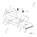
- FIG. 1 is a partial perspective schematic representation of a machine according to a first variant embodiment of the invention for the implementation of the process according to the invention
- FIG. 2 is a detail cutaway view that shows the heating means and a portion of the conveying plane of the machine that is shown in FIG. 1 ;
- FIG. 3 is a perspective schematic representation of a second variant embodiment of the machine according to the invention.
- FIG. 4 is a view that is similar to FIG. 2 of another variant embodiment of lighting means that form part of the machine according to the invention.
- the invention relates to an automatic process for inspecting and sorting non-metallic objects 1 that belong to at least two different categories and that pass in an essentially single-layer stream on a conveying plane 2 of a conveyor belt 3 for the purpose of performing at least one type of discrimination or characterization at the level of these objects based on at least one constituent or constructive characteristic of the latter.
- this process essentially consists of temporarily subjecting a surface or outside layer 4 of said objects 1 to the caloric radiation of at least one remote heating means 5 so as to deliver to each of these passing objects 1 a non-altering heat pulse that is identical for all of the objects in terms of thermal energy that is applied per unit of surface area in the conveying plane 2 , then to acquire at least one thermal image of each of said objects by means of at least one linear or matrix thermal sensor 6 , for example a thermal camera, this after a determined length of time has elapsed following the application of the heat pulse, then to classify or to categorize each passing object 1 based on the data that are contained in its thermal image(s) and to deliver a control or actuation signal for each object, and, finally, to separate the passing objects 1 based on their class or category and/or the corresponding control or actuation signal that is delivered.
- this process is characterized in that the data of the thermal image or images from each passing object 1 are processed to perform discrimination or characterization of the objects in terms of thickness of the surface layer 4 that is affected by the radiation, whereby the constituent material of said surface layer 4 at least of the passing objects 1 is identical for all of the objects.
- This process is also characterized in that for a given object 1 , the length of time that elapses between the application of the heating radiation and thermal imaging is adequate for ending in an essentially homogeneous distribution of the caloric energy that is absorbed in said surface layer 4 , such that the temperature difference after surface heating of said objects is essentially inversely proportional to the thickness of this surface layer 4 , while being short enough so that the phenomena of lateral thermal diffusion, cooling by radiation and convection are negligible.
- “negligible” characterizes phenomena whose influences have very little or no effect on the data provided by the thermal images and the results of the exploitation of these images (typically less than 10%, and even less than 5% of variation in the data provided).
- the discrimination or the characterization of said passing objects 1 is performed on the basis of differential data or by differential exploitation of data, obtained either from thermal images that are taken before and after application of the caloric radiation that is emitted by the heating means 5 or from the single thermal image taken after application.
- the heat pulse can affect the exposed surface layer 4 of each passing object 1 over its entire surface or only in certain zones.
- the intensity data provided by the thermal images directly make it possible to perform discrimination and therefore a sorting between the different categories of passing objects.
- the surface layer 4 that is involved for performing the discrimination or the categorization of objects 1 has a thickness of greater than 20 ⁇ m, advantageously between 20 ⁇ m and 2 mm, preferably between 30 ⁇ m and 1 mm, and the length of time that elapses between the application of the caloric radiation and the thermal imaging is on the order of several tenths of a second, preferably between 50 ms and 600 ms, and more preferably between 250 and 400 ms.
- the process may consist in taking a partial or total thermal image of each passing object 1 before its exposure to the radiation of the heating means 5 , whereby the discrimination or the characterization of said passing objects 1 is performed on the basis of differential data obtained from said thermal images taken before and after application of the caloric radiation emitted by the heating means 5 , whereby the images before and after exposure are taken by the same thermal sensor 6 or by two different sensors.
- the deposit of caloric energy that results from the application of the radiation 5 ′ emitted by the heating means 5 is essentially uniform and spread out evenly over the entire exposed surface 7 at the level of the conveying plane 2 .
- Such an arrangement requires the implementation of a suitable heating means 5 as well as a determined positioning of this means relative to the conveying plane 2 .
- the deposit of caloric energy carried out by the radiation 5 ′ that is emitted by the heating means 5 is by nature intermittent and limited to localized zones of the exposed surface 7 at the level of the conveying plane 2 , such as, for example, segments of lines or bands that extend in the direction in which the objects pass or the conveyor belt 3 moves, optionally circumscribed in the regions corresponding to objects 1 as they pass.
- Performing such an intermittent application of the caloric energy in the exposed zone or the heating zone 7 of the conveying plane can be achieved by using either a radiation source with discontinuous or intermittent emission or a source with continuous or constant emission whose radiation is interrupted spatially by an intermediate element (mask) between the source and the conveying plane.
- the first solution makes it possible, of course, to produce a gain in consumed power.
- each passing object 1 is carried out on the basis of the single thermal image taken after exposure, by differential exploitation of the data from the irradiated zones and non-irradiated zones of the surface, and therefore of the exposed surface layer 4 of the object in question.
- the window of application in the conveying plane of the caloric radiation defines an exposed surface 7 and therefore a heating zone in band form, preferably of small width, or of a line that extends essentially crosswise relative to the direction D in which the conveyor belt 3 moves or the objects 1 pass.
- the caloric radiation is a focused radiation, preferably of the infra-red type or with a majority infra-red component, and it is delivered by means of an application means 8 that is located at least a minimum distance above the conveying plane 2 , in particular at least slightly higher than the maximum height of the passing objects 1 .
- the portion of the caloric radiation that is produced by the heating means 5 and directed toward the conveying plane 2 is blocked by a reflective mask 5 ′′′ such that all of the radiation emitted by said heating means 5 is applied to the exposed surface 7 of the conveying plane 2 by a reflective and concentrating element that forms part of said heating means 5 and forms an application means 8 .
- the process may also consist in acquiring additional data relating to the passing objects 1 by means of at least one additional sensor 10 , for example selected from the group that is formed by magnetic detectors, spectrometers, and black and white or color vision cameras, and in combining the results of the exploitation of these additional data with the results of the exploitation of the data contained in the thermal image or images to perform the discrimination or the characterization of said passing objects 1 .
- additional sensor 10 for example selected from the group that is formed by magnetic detectors, spectrometers, and black and white or color vision cameras
- the data acquired by this sensor 10 can be used as a variant or in a supplementary manner to control said heating means 5 when the latter has an intermittent application.
- This invention also relates to, as the accompanying figures show diagrammatically and partially, an automatic machine 11 for inspecting and sorting non-metallic objects 1 that belong to at least two different categories and that pass in an essentially single-layer stream on a conveying plane 2 of a conveyor belt 3 (also forming part, if necessary, of the machine 11 ), making it possible to perform at least one type of discrimination or characterization at the level of these objects 1 based on at least one constituent or constructive characteristic of the latter.
- This machine 11 comprises, on the one hand, at least one remote heating means 5 that can temporarily subject a surface or outside layer 4 of said passing objects 1 to its caloric radiation so as to deliver to each of these passing objects a non-alternating heat pulse that is identical for all of these objects in terms of thermal energy that is applied per unit of surface area in the conveying plane 2 , and, on the other hand, at least one linear or matrix thermal sensor 6 , for example a thermal camera, placed at a determined distance downstream from said at least one heating means 5 in the direction of passing and able to acquire at least one thermal image of each of said objects and, finally, at least one processing unit 12 that is able to classify or categorize each passing object 1 based on the data contained in its thermal image or images and to deliver a control or actuation signal for each object, whereby said at least one processing unit 12 is connected to at least one means 13 that can separate said passing objects 1 based on their category or class and the corresponding control or actuation signal that is delivered.
- at least one processing unit 12 is connected to at
- This machine is characterized in that the distance d that separates the zone in which the thermal radiation or each thermal radiation is applied, or the heating zone 7 , from the zone in which the respectively associated thermal imaging zone or each respectively associated thermal imaging zone 7 ′ is applied, is, on the one hand, long enough so that the caloric energy that is absorbed in a surface layer 4 of the constituent material of each passing object 1 has an essentially homogenous distribution in this layer, and, on the other hand, short enough so that the effects of the phenomena of lateral thermal diffusion, cooling by radiation and convection are negligible.
- the data of the thermal image or images from each passing object 1 are processed to perform discrimination or characterization of the objects in terms of the thickness of said surface layer 4 , whereby the constituent material of the surface layer 4 at least of the passing objects 1 is identical for all of the objects.
- the processing unit 12 performs the discrimination or the characterization of said passing objects 1 on the basis of differential data or by differential exploitation of data, obtained either from thermal images taken before and after application of the caloric radiation that is emitted by the heating means 5 , or from the single thermal image taken after application.
- the conveyor belt 3 that forms the conveying plane 2 has a constant displacement speed, and said at least one heating means 5 and said at least one thermal sensor 6 are placed above said conveying plane 2 .
- the distance d that separates the zone in which the thermal radiation or each thermal radiation is applied, or heating zone 7 , from the zone in which the respectively associated thermal imaging zone or each thermal imaging zone 7 ′ is applied is, on the one hand, short enough so that the effects of the phenomena of lateral thermal diffusion, of cooling by radiation, and of convection are negligible, and, on the other hand, long enough so that the caloric energy that is absorbed in a surface layer 4 of the constituent material of each passing object 1 has an essentially homogeneous distribution in this layer.
- the radiation 5 ′ that is delivered by the remote heating means 5 is directed so as to affect a narrow band or a line of the conveying plane 2 that forms an exposed surface or a heating zone 7 and that extends essentially crosswise relative to the direction D in which the conveyor belt 3 moves or the objects 1 pass, and said radiation 5 ′ is a focused radiation, preferably of the infra-red type or at least with a majority infra-red component.
- the heating means 5 consists of the combination, on the one hand, of a radiation source 5 ′′ with a tubular focal point or an alignment of radiation sources with essentially specific or elongated focal points with, on the other hand, a deflector element 8 and a radiation-concentrating element 5 ′, and the two above-mentioned components 5 ′′ and 8 that form said heating means 5 have a shaped extension, extend crosswise to a substantial portion of the width of the conveying plane 2 , preferably essentially over this entire width, and carry out in mutual cooperation a deposit of essentially uniform and homogeneous caloric energy over the entire surface of the heating zone 7 in belt form of the conveying plane 2 that receives the focused radiation.
- the tubular radiation source 5 ′′ consists of a radiant tube that comprises a reflective mask or a layer 5 ′′′, for example in the form of a metallic deposit, on the surface of said tube 5 ′′ that is rotated toward the conveying plane 2 , such that approximately the entire radiation that is emitted is directed toward said conveying plane 2 by the deflecting and concentrating element 8 that is combined with said radiant tube 5 ′′, for example of the type that emits a radiation in the middle infra-red range, preferably with wavelengths that are longer than 2000 nm.
- the thermal sensor or sensors 6 carry out, for each passing object 1 , an imaging before and after the exposure of said object to or with a caloric radiation 5 ′, and the processing unit 12 performs discrimination or categorization of said passing objects 1 on the basis of differential data obtained from their thermal images that are acquired before and after exposure to said caloric radiation 5 ′.
- the heating means 5 consists of a laser source 5 ′′, of the continuous or intermittent emission type, combined with an application device 8 with two-dimensional scanning (for example, in the form of two pivoting mirrors with perpendicular axes), whereby the deposit of caloric energy is of an intermittent nature and limited to the localized zones of the exposed surface 7 at the level of the conveying plane 2 , such as, for example, segments of lines or bands that extend in the direction in which the objects pass or the conveyor belt 3 moves, optionally circumscribed in the regions corresponding to objects 1 as they pass.
- the processing unit 12 can perform discrimination or characterization of each passing object 1 on the basis of the single thermal image taken after exposure, by differential exploitation of the data from irradiated zones and non-irradiated zones of the surface 7 , and therefore the exposed part of the surface layer 4 of the object 1 in question.
- the machine 11 can also comprise a device for locating and delimiting the apparent surface of passing objects 1 on the conveying plane 2 that is located upstream from the heating means 5 in the direction of passage, whereby the data acquired by this device for locating and delimiting the apparent surface are used to control said heating means 5 in the form of a [laser source 5 ′′/application device 8 with scanning] unit.
- the latter optionally can acquire—in real time—additional data relative to the passing objects with a nature other than thermal.
- it can then comprise at least one additional sensor 10 that is selected from the group that is formed by the magnetic detectors, spectrometers, black and white or color vision cameras, and the results of the exploitation of these additional data are combined in a processing unit 12 with the results of the exploitation of the data that are contained in the thermal image or images for performing the discrimination or the characterization of said passing objects 1 .
- the above-mentioned device for locating and delimiting/distinguishing objects 1 optionally can consist of such an additional sensor 10 placed upstream from the heating zone 7 .
- machine 11 further comprises, in addition to the means described explicitly above and illustrated in the figures, all of the other means (equipment and software) that are necessary for the implementation of the process described above, including its programming by a user or operator and its linking with other installations or systems.
- equipment and software that are necessary for the implementation of the process described above, including its programming by a user or operator and its linking with other installations or systems.
- FIGS. 1 and 3 The general principle is presented in FIGS. 1 and 3 .
- the machine 11 comprises at least one heating means 5 of the passing objects or products 1 , which integrates as a radiation source 5 ′′ either a laser source or a thermal-type lamp (Globar, incandescent lamp, halogen lamp, Xenon flash lamp, etc.) that produces the energy that is preferably located in wavelengths that are greater than 2000 nm, whereby the unit is set above a conveyor belt 3 , and an application means 8 of the deviation or focusing type, for example an elliptical mirror or reflector, which creates a zone 7 of strong lighting and of small width over the entire width of the conveyor belt 3 . Any object 1 as it passes on this conveyor belt is therefore subjected to a heat pulse of several milliseconds, according to the characteristics of the heating means 5 .
- a radiation source 5 ′′ either a laser source or a thermal-type lamp (Globar, incandescent lamp, halogen lamp, Xenon flash lamp, etc.) that produces the energy that is preferably located in wavelengths that are greater
- a linear or matrix thermal camera 6 visualizes at least one measurement zone 7 ′ where image acquisition is done after diffusion of the heat in the surface layer 4 of the object 1 or product.
- a control or reference zone 7 ′′ that is placed before heating can also be visualized to indicate the surface temperature of objects 1 before heating. If the camera 6 is a matrix camera, the field of vision can be selected as indicated in FIGS. 1 and 3 , such that the same camera visualizes the two zones 7 ′ and 7 ′′ at the same time. If the camera 6 is a linear camera, the zone 7 ′′ should be visualized by a second camera, not shown, and preferably identical.
- the heating zone 7 and the rear imaging zone 7 ′ are separated by the distance d, variable according to the application.
- another sensor 10 of a different nature can be placed on the same conveyor belt, before or after the camera 6 .
- the information that is provided by the sensor 10 can be combined with that provided by the camera 6 to result in a combined classification of objects 1 , by a suitable computer and algorithm (processing unit 12 ).
- processing unit 12 At the end of the conveyor belt, some of the nozzles of the nozzle bar that form the separation means 13 are actuated to eject the selected objects.
- the objects to be sorted 1 are, for example, cardboard-paper, plastics (packages, films, bags, ground waste of electronic or automobile origin) or biological wastes to be sorted for composting or other biological treatment.
- the objects 1 are generally stored in a sorting center primarily in two forms, loose or in balls. In general, they remain there long enough for their surface temperature to be spread out evenly, but this is not always the case, in particular in the case of outside storage (effects of the sun, rain, frost). After loading on the sorting line integrating the machine 11 , their temperature can therefore vary in a range from one to several degrees. Alternately, in a recycling center, the objects 1 can be passed through a hot washing phase just before the sorting zone, and their temperature is then spread out more evenly.
- Each object 1 is first accelerated on the conveyor belt 3 and then stabilized.
- the speed of the conveyor belt is optimized based on the nature of the objects 1 to ensure a spreading on a single layer, while avoiding the sliding or rolling for the large majority of the objects.
- the speeds that are generally adopted vary from 1 to 3 m/s.
- Each object 1 first passes through the control zone 7 ′′, where a first thermal image can be acquired: it indicates the starting temperature of the object 1 .
- the object clearly becomes detached by its colder temperature on the bottom of the conveyor belt 3 , because the latter is continuously heated by the means 5 , whereas the object makes only a rapid passage.
- the object 1 then passes through the zone 7 where it receives a heat pulse that is also distributed over its entire surface layer 4 .
- This zone 7 has a preferred width of 5 to 10 cm. This width is to be reduced to characterize as well as possible the moment of passing.
- the heat that is received is spread out evenly in its surface layer 4 if the object is thin (less than 0.5 mm), and it is diffused in the depth of the object if the latter is deep or thick (see modeling below).
- the distance d is selected based on the nature of the materials and the surface layer thicknesses of the objects to be sorted. Its order of magnitude is 100 to 600 mm.
- the cooling by radiation of the surface layer of the object has a negligible range, as will be shown below.
- a second thermal image is acquired and makes it possible to know the temperature of the object 1 after thermal stabilization.
- the difference in temperatures before and after heating provides the overall heating of the object 1 that is considered.
- One (or more) other sensor(s) 10 placed in the same zone, can provide important additional information and in particular:
- the measured heating makes it possible to deduce the thickness of the first layer or surface layer 4 . It thus is possible, for example, to differentiate paper from cardboard, because they differ only by their specific mass (more or less than 224 g/m 2 for the French standards), which mass is directly linked to the thickness thereof.
- the machine 11 in the form of a combined classifier that uses the data from sensors 6 and 10 makes it possible to make a decision as to whether or not to eject each object 1 .
- Only a single row of ejection nozzles 13 has been shown here, but this example is in no way limiting: it is possible in particular to have a ternary sorting, with two parallel rows of nozzles, on the same side or two opposite sides of the stream of products or objects 1 .
- a variant of the operation above is to take more than two images during the passing of the object, which is easy with a matrix camera. It may actually be advantageous in some cases to use intermediate images, taken either during the heating phase or during the heat diffusion phase.
- T is the temperature
- t is the elapsed time
- x is the depth
- ⁇ is the diffusivity of the product.
- the radiation that is received by the object of its environment, whose temperature is very close broadly compensates for this emission.
- the heating phase provided approximately 800 J/m 2 (see above)
- the heat is evacuated only slowly by radiation (in more than 4 seconds for the thinnest paper, and up to one minute for a thick cardboard). It is therefore possible to disregard the cooling by radiation of these objects between the two instances of imaging mentioned, spaced by at least one half-second.
- the heating means 5 can come in various embodiments, each accounting for specific advantages and limitations.
- a first possibility of carrying out the controlled heating of objects 1 consists in implementing middle infra-red radiation (MIR).
- MIR middle infra-red radiation
- a concentrated lighting on the wavelengths of greater than 2000 nm is desirable.
- the absorbance in this range is greater than 80% for all of the organic products.
- the penetration depth of the radiations is low (beyond 3000 nm, attenuation of 90% after about 20 ⁇ m for water), which guarantees surface heating. It is thus ensured that only the first layer of the product is affected by the flash of heat.
- this reasoning also means that too thin a product does not stop all of the radiation: a plastic bag that is 10 ⁇ m thick will collect only 10 to 50% of the energy depending on the wavelengths.
- FIG. 2 of the accompanying drawings The diagram of a variant embodiment of the heating means 5 in the form of a lighting system according to the invention is presented in FIG. 2 of the accompanying drawings.
- this temperature is suitable for our problem.
- the radiation of a tube that is 1 cm in diameter is enough to provide 2500 W per linear meter.
- an elliptical reflector 8 is placed around the tube 5 ′′, and it is designed so that one of the focal points is the tube itself, whereby the other is close to the conveyor belt. Thus, any ray that passes through the reflector 8 is reflected so as to touch the conveyor belt in the zone 7 .
- the zone 7 has a width of approximately 5 cm over the conveying plane 2 that is formed by the conveyor belt 3 .
- FIG. 2 is purely by way of indication.
- FIG. 4 of the accompanying drawings illustrates a variant embodiment of the heating means 5 relative to the one that is shown in FIG. 2 .
- the radiating source that is shaped, for example, in the form of a tube is provided with a reflective layer 5 ′′′ that limits the angular diffusion of the radiation and is located on the face of the tube that is opposite to the conveying plane 2 .
- this limiting layer of the diffusion angle advantageously can be completed by a reflector 8 that consists of, for example, upper and lateral reflective parts, for example portions of plane mirrors. These means make it possible to direct the rays that are emitted by the tube toward the conveying plane by concentrating them, but without focusing them.
- the reference 14 ′ designates a ray that is retracted into the zone 7 of the conveying plane using the reflector 8 .
- Another possibility for carrying out the controlled heating of the objects consists in implementing a halogen lighting.
- This radiation mode is advantageous for reducing the lighting number in a multi-sensor application.
- a third possibility for carrying out the controlled heating within the scope of the invention consists in implementing a pulsed lighting or lighting by repeated pulses.
- Heating means based on repetitive flashes of short duration (1 ms, and even 10 ⁇ s) exist. It is possible to produce these flashes with Xenon lamps, or movie projectors. However, these flashes are in general optimized to operate in the visible domain, and their yield in infra-red means is relatively low. Despite this drawback, they offer the advantage of a moment of perfectly defined heating.
- a fourth concrete possibility for carrying out the controlled heating of the objects 1 as they pass consists in implementing lighting by laser, preferably infra-red.
- Lighting by laser, combined with a controlled two-dimensional scanner, is certainly more complex, but it offers several advantages relative to thermal sources as indicated below.
- a variant consists in creating a heated line with the laser by leaving an adjacent line unheated.
- this line is advantageous for this line to be parallel to the direction of advance of the conveyor belt.
- the laser makes it possible to concentrate the energy on the zones of interest and therefore to reduce significantly the energy needs, as well as the associated fire risks. If the laser is placed downstream from a vision system that has located the objects, it can be directed only to the points where the objects are present. By combining with the preceding arrangement, it is possible to scan the lines that are parallel to the advance of the conveyor belt 3 , but only where objects 1 are present.
- a laser 5 ′′ creates a collimated beam, a beam that is deflected by a set of two mirrors with perpendicular axes 8 toward an object 1 , where alternating heated/non-heated lines are described, lines that are preferably parallel to the direction of advance D of the objects.
- the laser can operate continuously or in pulsed mode. Before the image acquisition, the objects 1 , as before, are allowed to stabilize their temperature during the transit of distance d. The control zone 7 ′′ is no longer necessary.
- any heating of the conveyor belt 3 is avoided, and the energy requirements are reduced drastically. If a filling rate of the belt of about 20% is assumed, and if 50% of the surface of each object is heated, 10% of the preceding energy is sufficient to obtain an equivalent thermal effect. An energy of 200 W instead of 2000 W is therefore sufficient. If a “survey” of 10% of the surface of each object, which is entirely realistic, is satisfactory, 40 W is sufficient. If a heating of 1° C. in the case of a thick product (200 ⁇ m) and of 4° C. for a thin product (50 ⁇ m) are considered to be sufficient, the requirements are also reduced by a factor of 4. The smallest laser that is suitable for the application then has a power of 10 W.
- a first application of the invention relates to papers, in particular the differentiation between printed forms and cardboard-type packaging products.
- This application involves a structured (fibrous) product that is greatly diffusing and opaque. In the MIR wavelengths, it is very absorbent, and its emissivity is high (>0.9) and constant.
- the differentiation should relate to two printed products of close appearance:
- An image is taken after stabilization or here after 224 ms, the longest homogenization time of the two products.
- the movement is from about 670 mm between the two points. This is sufficient just to have the two image bands in the same image, if a 320 ⁇ 240-pixel camera is assumed, with pixels whose image on the belt has 4 mm on the side.
- Heating with MIR radiation of approximately 5.6° C. is calculated for the magazine cover and of 3.6° C. for the small cardboard. The difference of these values is significant and measurable.
- a second application of the invention relates to the products—in particular the packages—that are made of a multilayer polymer material (PET).
- PET multilayer polymer material
- uncolored transparent bottles which are produced either in a single PET layer, or in at least three juxtaposed layers, whereby the center layer consists of a material that forms a barrier to a gas (O 2 or CO 2 ).
- This material is, for example, nylon.
- Another case depicted, close but simpler, is the presence of labels or plastic sleeves on the surface, even after washing. In this case, it is necessary to characterize the presence of the label on the surface.
- the heat penetrates primarily the first thickness (surface layer).
- the layers are not made integral, and the conduction toward the second layer is very limited. The phenomenon is accentuated by the fact that during the heating, the optical discontinuity creates an upward reflection of a portion of the incident energy.
- a single-layer bottle generally has a thickness of approximately 400 ⁇ m. If it is three-layer, the central layer is thin, or approximately 20 ⁇ m, and it separates two layers of about 190 ⁇ m each.
- a third application of the invention relates to the sorting of bags and films that are made of plastic material.
- the plastic films are made of PE- or PP-type polyolefins, and they are difficult to distinguish by spectroscopy of the solid objects that are made of the same materials.
- the HDPE with an internal layer of carbon black a particular type of multilayer, have spectra that are very close to the LDPE plastic bags. It then is possible, as for the preceding case, to sort them via differences in thickness, which are very significant. This type of sorting comes in addition to an infra-red spectrometer that has already determined the presence of PE (LD or HD). Since their thermal inertia is low, the image acquisition is to be done quickly after the heating zone for an ideal contrast, before the total stabilization of the HDPE bottles.
- a fourth application of the invention relates to the purification of compost.
- a stream of primarily organic products is obtained by screening starting from a stream of crude wastes.
- an 80 mm mesh makes it possible to obtain from the fines (passing fraction) a stream that is concentrated to more than 80% organic material (food scraps, kitchen scraps, green waste), i.e., highly aqueous fines.
- the products in question are nearly all opaque and therefore readily absorb the caloric radiation in a narrow surface layer.
- the minerals and the glasses have a lower thermal capacity than water. However, they are always thick (>2 mm) and diffuse at least four times faster than water: they therefore quickly become colder than water, and this is visible from the heating phase.
- the metals have a strong reflectivity (90 to 95%), and they heat very little. In addition, their emissivity is low, and for a given heating, they emit very little radiation: they therefore appear almost black. This is true from the control photo (before heating), if they are in thermal equilibrium.
- the light pollutants are very sensitive to an MIR-type radiation, as already indicated above: they have little thermal capacity, and they are thin. Next, they diffuse slightly and keep an almost constant temperature for several seconds.
- thermography cameras combined with elements for heating by radiation, to perform the real-time sorting of various types of products, and in particular:
- this invention proposes a simple method, suitable in the case of thin and non-metallic products, whose thickness is spread in the range of 20 ⁇ m-2 mm.
- the time periods between heating and detection are, furthermore, short enough to allow a quick decision, and a real-time sorting with a compact machine, even for rapidly passing products.
Abstract
Description
-
- They operate without cooling devices;
- The temperature resolutions that are available are very fine, about 0.1° C., and even 0.01° C. Whereby no system is perfectly thermally balanced, primarily for slight temperature fluctuations, the contrast between the different objects of a scene is good;
- The spatial resolutions are good: 320×240 pixels is a common value;
- The response times are compatible with the video flows, or 25 images/second.
-
- GB-A-2 278 440 describes a system that makes it possible to sort products of different natures (diamonds/stones or gravel) based on their respective emissivity. Its implementation requires a uniform temperature of products before treatment.
- WO 96/23604 describes a system for separating products producing a preliminary heating of said products and then a segregation of the latter based on the status of their temperature relative to predetermined temperature ranges. However, this document does not absolutely specify on what bases rests the discrimination that is performed.
- FR-A-2 697 450 discloses a process and a device for sorting vegetable products. The discriminating factor is the moisture level that makes it possible to differentiate the good products (fruits and vegetables) from the products to be eliminated (cores, stems, lignified parts) based on their nature (high level/low level).
- US-A-2002/0027943 proposes a system and a process for sorting packages based on their nature (constituent material). A prolonged heating whose energy cost during use is unacceptable and that does not allow high rates is noted.
-
- The position of the
object 1 on theconveyor belt 3, in the case where the thermal contrast is inadequate to locate it well in the thermal images: the mostsuitable sensor 10 is a color vision camera; - Other criteria of appearance, in particular its color and the characteristics of its printed patterns (vision camera);
- The constituent material of the object, provided by, for example, an infra-red spectrometer as described in the above-mentioned French filing and the PCT filing of the Pellenc Company.
- The position of the
∂T/∂t=α·∂ 2 T/∂x 2
Td=e 2/4α, where e is the thickness that is attained by the thermal flux.
Td=1.8 s, and for 2 mm, there is Td=7.2 s.
ΔW=4·σ·T 3 ΔT=6.16·ΔT
ΔT=18° C., then ΔW=111 W/m2.
-
- It is not possible to metallize the half-
tube 5″, and half of the energy is not focused. The direct rays that reach theconveyor belt 3 without passing through thereflector 8 also heat the products, but the corresponding heating moment is poorly defined; - The absorbance of the
products 1 is not close to 100% in this spectral range. For paper that is medium clear in color or white, it reflects or diffuses the bulk of the energy. The heating is therefore only 5% to 10% of the preceding value, or about 0.25° C. for a cardboard of 200 μm, and 1° C. for a paper of 50 μm.
- It is not possible to metallize the half-
-
- By its monochromatic nature, it makes it possible to act specifically on certain materials whose absorption can be maximum at the wavelength of the laser;
- It even makes it possible to select the length of time of heating of the object based on other criteria, such as the constituent material, if this indication is provided in advance by another
sensor 10, such as an infra-red spectrometer.
-
- Small packaging cardboards whose thicknesses vary from 250 to 400 μm,
- Magazines and advertisements: their inside sheets have thicknesses of approximately 40 μm, but the covers, which are seen more frequently, reach 150 μm.
-
- Small thin cardboards: Th_c=e2/2·a=0.252/(2×0.14) s=0.224 s=224 ms is assumed, and for
- Magazine covers: Th_m=0.162/(2×0.14)=92 ms is assumed.
-
- Single-layer: Th_m=e2/2·a=0.42/(2×0.14) s=0.571 s=571 ms.
- Three-layer (first layer): Th_t=0.192/(2×0.14)=129 ms.
-
- Light pollutants: plastic types (flexible or rigid), and more or less contaminated papers;
- Heavy pollutants: glass, rocks, metals, ashes.
-
- The hottest: plastics and papers;
- The biological products, moderately heated;
- The minerals and the glasses, slightly heated;
- The metals, almost black, and this from the first image.
-
- Differentiation of paper and cardboards on the basis of the thickness of the first layer;
- Differentiation of single-layer and multi-layer plastic packages;
- Differentiation of thick plastics (more than 1 mm) per material;
- Differentiation of various pollutants (plastics, papers, metals, glasses, minerals) in a biological stream that is intended for composting.
-
- The calorific capacity per unit of surface area is directly proportional to the thickness of the surface layer of the heated material and therefore for a given surface radiation level, the temperature rise at equilibrium is inversely proportional to this thickness. It is possible to deduce therefrom the thickness for a known material;
- The time periods that are necessary for reaching the thermal equilibrium are short enough (less than 500 ms) so that the other thermal phenomena (lateral conduction, cooling by radiation or convention) are negligible;
- The thicknesses are sufficient to ensure an almost total absorption of the heating radiation, at least for certain wavelengths. Below 20 μm, these conditions are no longer complied with.
Claims (29)
Applications Claiming Priority (3)
| Application Number | Priority Date | Filing Date | Title |
|---|---|---|---|
| FR0513507 | 2005-12-30 | ||
| FR0513507A FR2895688B1 (en) | 2005-12-30 | 2005-12-30 | AUTOMATIC METHOD AND MACHINE FOR INSPECTING AND SORTING NON-METALLIC OBJECTS |
| PCT/FR2006/002900 WO2007077367A1 (en) | 2005-12-30 | 2006-12-28 | Method and machine for automatically inspecting and sorting objects according to their thickness |
Publications (2)
| Publication Number | Publication Date |
|---|---|
| US20080302707A1 US20080302707A1 (en) | 2008-12-11 |
| US8083066B2 true US8083066B2 (en) | 2011-12-27 |
Family
ID=36928427
Family Applications (1)
| Application Number | Title | Priority Date | Filing Date |
|---|---|---|---|
| US12/159,629 Expired - Fee Related US8083066B2 (en) | 2005-12-30 | 2006-12-28 | Method and machine for automatically inspecting and sorting objects according to their thickness |
Country Status (12)
| Country | Link |
|---|---|
| US (1) | US8083066B2 (en) |
| EP (1) | EP1965929B1 (en) |
| JP (1) | JP5011309B2 (en) |
| KR (1) | KR101305278B1 (en) |
| CN (1) | CN101351280B (en) |
| AT (1) | ATE467465T1 (en) |
| CA (1) | CA2635654C (en) |
| DE (1) | DE602006014303D1 (en) |
| ES (1) | ES2345277T3 (en) |
| FR (1) | FR2895688B1 (en) |
| PL (1) | PL1965929T3 (en) |
| WO (1) | WO2007077367A1 (en) |
Cited By (14)
| Publication number | Priority date | Publication date | Assignee | Title |
|---|---|---|---|---|
| US20110147277A1 (en) * | 2008-09-11 | 2011-06-23 | Damien Harding | Sorting mined material |
| US20110174904A1 (en) * | 2008-09-11 | 2011-07-21 | Technological Resources Pty. Limited | Sorting mined material |
| US20110186660A1 (en) * | 2008-09-11 | 2011-08-04 | Technological Resources Pty. Limited | Sorting mined material |
| US20130141115A1 (en) * | 2011-12-06 | 2013-06-06 | Universite De Savoie | Process and Installation for Inspection and/or Sorting Combining Surface Analysis and Volume Analysis |
| US20140214376A1 (en) * | 2013-01-31 | 2014-07-31 | Fujitsu Limited | Arithmetic device and arithmetic method |
| US20140214375A1 (en) * | 2013-01-31 | 2014-07-31 | Fujitsu Limited | Arithmetic apparatus and arithmetic method |
| CN104310036A (en) * | 2014-09-28 | 2015-01-28 | 成都三可实业有限公司 | Conveying device for candy sticks |
| US9517491B2 (en) | 2014-06-27 | 2016-12-13 | Key Technology, Inc. | Method and apparatus for sorting |
| US10195647B2 (en) | 2016-01-15 | 2019-02-05 | Key Technology, Inc | Method and apparatus for sorting |
| US10363582B2 (en) | 2016-01-15 | 2019-07-30 | Key Technology, Inc. | Method and apparatus for sorting |
| US20210114827A1 (en) * | 2019-10-22 | 2021-04-22 | Mecal Machinery S.R.L. | Loading/unloading units for profiles |
| US20220080464A1 (en) * | 2019-01-31 | 2022-03-17 | Saint-Gobain Ecophon Ab | System and method for recycling planar objects |
| US20220148897A1 (en) * | 2019-03-20 | 2022-05-12 | Osram Opto Semiconductors Gmbh | Method for sorting optoelectronic semiconductor components and device for sorting optoelectronic semiconductor components |
| US20230364652A1 (en) * | 2022-05-12 | 2023-11-16 | Canon Kabushiki Kaisha | Sorting apparatus for sorting objects and measurementapparatus |
Families Citing this family (29)
| Publication number | Priority date | Publication date | Assignee | Title |
|---|---|---|---|---|
| FR2920680B1 (en) * | 2007-09-06 | 2016-07-22 | Pellenc Sa | METHOD FOR VISIONIC SELECTION OF HARVESTED BERRIES, SORTING CHAIN AND SORTING MACHINE USED FOR CARRYING OUT SAID METHOD |
| DE102009059724A1 (en) * | 2009-12-18 | 2011-06-22 | RWE Power AG, 45128 | Method and device for testing a shaped fuel body |
| WO2012098430A1 (en) * | 2011-01-19 | 2012-07-26 | Vistek Isra Vision Yapay Gorme Ve Otomasyon Sanayi Ve Ticaret Anonim Sirketi | A transparent object positioning system |
| US8812149B2 (en) * | 2011-02-24 | 2014-08-19 | Mss, Inc. | Sequential scanning of multiple wavelengths |
| EP2503322B1 (en) * | 2011-03-25 | 2016-03-09 | Detlev Gertitschke | Device for inspecting small pharmaceutical products |
| CN102241332A (en) * | 2011-06-20 | 2011-11-16 | 利奥传感科技(广州)有限公司 | Automatic shunting method and system of conveyor belt for preventing continuous errors |
| US10229348B2 (en) * | 2011-07-05 | 2019-03-12 | Bernard Fryshman | Induction detector systems |
| US10339426B2 (en) * | 2011-07-05 | 2019-07-02 | Bernard Fryshman | Induction system for crowd monitoring |
| EP2647949A1 (en) * | 2012-04-04 | 2013-10-09 | Siemens VAI Metals Technologies GmbH | Method and device for measuring the flatness of a metal product |
| DE102013214550B4 (en) * | 2013-07-25 | 2022-09-08 | Bayerische Motoren Werke Aktiengesellschaft | Vehicle with a heating device |
| JP6711755B2 (en) * | 2013-11-01 | 2020-06-17 | トムラ・ソーティング・エヌ・ヴィ | Method and device for detecting substances |
| US9201018B2 (en) * | 2013-12-23 | 2015-12-01 | Honeywell Asca Inc. | Optimized spatial resolution for a spectroscopic sensor |
| ES2578368B1 (en) * | 2014-12-23 | 2017-02-17 | Environmental Green Engineering, S.L. | MACHINE WITH ARTIFICIAL VISION FOR THE AUTOMATIC SEPARATION OF BLACK COLOR PLASTIC WASTE BY CHEMICAL COMPOSITION |
| US11278937B2 (en) * | 2015-07-16 | 2022-03-22 | Sortera Alloys, Inc. | Multiple stage sorting |
| KR101595707B1 (en) * | 2015-10-07 | 2016-02-18 | 서울과학기술대학교 산학협력단 | Defect Depth Measuring Method of Metallic sheet using Pulse Thermography |
| CA3012284C (en) * | 2016-02-08 | 2022-08-23 | Egg-Chick Automated Technologies | Apparatus and method to detect upside down eggs |
| FR3048369B1 (en) * | 2016-03-01 | 2018-03-02 | Pellenc Selective Technologies | MACHINE AND METHOD FOR INSPECTING FLOWING OBJECTS |
| CN107661862B (en) * | 2016-07-27 | 2020-11-03 | 边隆祥 | Express delivery automatic sorting array type camera system |
| CN106040611A (en) * | 2016-08-05 | 2016-10-26 | 武汉理工大学 | Retired automobile nonferrous metal thermal imaging sorting method |
| CN106540884B (en) * | 2016-12-09 | 2018-10-12 | 贵州西南工具(集团)有限公司 | A kind of slide plate sorting unit on slide plate baling line and method |
| FR3066415B1 (en) | 2017-05-19 | 2019-08-02 | Pellenc Selective Technologies | PNEUMATIC EJECTION DEVICE AND SORTING MACHINE COMPRISING SUCH A DEVICE |
| JP7109020B2 (en) * | 2018-09-07 | 2022-07-29 | 池上通信機株式会社 | Package product inspection device and inspection method |
| FR3101792B1 (en) | 2019-10-14 | 2021-10-01 | Pellenc Selective Tech | Automatic machine for sorting or inspecting moving objects, equipped with a cleaning device |
| CN111649919B (en) * | 2020-06-12 | 2022-11-18 | 山东中衡光电科技有限公司 | Visual inspection test bed that circular-arc simulation conveyer belt was indulged and is torn |
| CN112044780B (en) * | 2020-08-14 | 2021-06-29 | 郑州科技学院 | Measurement and control machine for intelligent manufacturing |
| CN113319005A (en) * | 2020-09-25 | 2021-08-31 | 怀化正好制药有限公司 | Automatic change machine of sieve impurity |
| CN112670216A (en) * | 2020-12-30 | 2021-04-16 | 芯钛科半导体设备(上海)有限公司 | Device for automatically identifying articles in wafer box |
| WO2023031710A1 (en) * | 2021-08-31 | 2023-03-09 | Ricoh Company, Ltd. | Thermographic inspection apparatus and inspection method |
| JP2023035191A (en) * | 2021-08-31 | 2023-03-13 | 株式会社リコー | Image acquisition device, inspection device, and image acquisition method |
Citations (25)
| Publication number | Priority date | Publication date | Assignee | Title |
|---|---|---|---|---|
| US4118309A (en) * | 1976-12-10 | 1978-10-03 | Atlantic Richfield Company | Separation and recovery of heat carriers in an oil shale retorting process |
| US4152245A (en) * | 1977-12-02 | 1979-05-01 | Atlantic Richfield Company | Separation of rock solids from heat carriers in an oil shale retorting process |
| US4513384A (en) * | 1982-06-18 | 1985-04-23 | Therma-Wave, Inc. | Thin film thickness measurements and depth profiling utilizing a thermal wave detection system |
| US4768158A (en) * | 1986-01-25 | 1988-08-30 | Kajima Corporation | Apparatus and method for diagnosing deterioration of smokestack |
| US4996426A (en) * | 1989-09-11 | 1991-02-26 | National Research Council Of Canada | Device for subsurface flaw detection in reflective materials by thermal transfer imaging |
| FR2697450A1 (en) | 1992-10-30 | 1994-05-06 | Felter Christian | Fruit or vegetables sorting method for use on conveyor - using video camera to detect variations of infra red radiation from surface of object on conveyor. |
| US5344026A (en) * | 1991-03-14 | 1994-09-06 | Wellman, Inc. | Method and apparatus for sorting plastic items |
| GB2278440A (en) | 1993-05-26 | 1994-11-30 | De Beers Ind Diamond | Particle classification based on thermal properties |
| WO1996023604A1 (en) | 1995-02-01 | 1996-08-08 | Beloit Technologies, Inc. | Thermal imaging refuse separator |
| US6112903A (en) * | 1997-08-20 | 2000-09-05 | Eftek Corporation | Cullet sorting by differential thermal characteristics |
| US20020027943A1 (en) * | 2000-08-30 | 2002-03-07 | Nec Corporation | Display on which a measurement result can be known only by viewing a measurement piece, and an apparatus for identifying a plastic material by using the display, and to accordingly make a selection simpler, cheaper and surer |
| US6367968B1 (en) * | 1999-07-21 | 2002-04-09 | General Electric Company | Thermal resonance imaging method |
| US6394646B1 (en) * | 1999-04-16 | 2002-05-28 | General Electric Company | Method and apparatus for quantitative nondestructive evaluation of metal airfoils using high resolution transient thermography |
| US6592252B2 (en) * | 2000-10-17 | 2003-07-15 | National Institute Of Advanced Industrial Science And Technology | Method for measuring thermal diffusivity and interface thermal resistance |
| US20040005147A1 (en) * | 2000-07-24 | 2004-01-08 | Wenling Wang | Heat treatment apparatus, calibration method for temperature measuring system of the apparatus, and heat treatment system |
| US6845869B1 (en) * | 1999-05-06 | 2005-01-25 | Graf Von Deym Carl-Ludwig | Sorting and separating method and system for recycling plastics |
| US6914678B1 (en) * | 1999-03-19 | 2005-07-05 | Titech Visionsort As | Inspection of matter |
| US7060991B2 (en) * | 2002-04-11 | 2006-06-13 | Reilly Thomas L | Method and apparatus for the portable identification of material thickness and defects along uneven surfaces using spatially controlled heat application |
| US7222738B1 (en) * | 2003-01-29 | 2007-05-29 | Fmc Technologies, Inc. | Sorting system for multiple conveyor belts |
| US20080144049A1 (en) * | 2006-12-15 | 2008-06-19 | General Electric Company | Method and apparatus for thermographic nondestructive evaluation of an object |
| US7419298B2 (en) * | 2005-05-24 | 2008-09-02 | United Technologies Corporation | Thermal imaging method and apparatus |
| US20080257793A1 (en) * | 2007-01-05 | 2008-10-23 | Valerio Thomas A | System and method for sorting dissimilar materials |
| US7549789B2 (en) * | 2007-06-20 | 2009-06-23 | General Electric Company | Method and apparatus for thermographic nondestructive evaluation of an object |
| US7573582B2 (en) * | 2003-09-05 | 2009-08-11 | Kabushiki Kaisha Toshiba | Method for monitoring film thickness, a system for monitoring film thickness, a method for manufacturing a semiconductor device, and a program product for controlling film thickness monitoring system |
| US7591583B2 (en) * | 2005-05-18 | 2009-09-22 | Federal-Mogul World Wide, Inc. | Transient defect detection algorithm |
Family Cites Families (9)
| Publication number | Priority date | Publication date | Assignee | Title |
|---|---|---|---|---|
| JPS5441662U (en) * | 1977-08-29 | 1979-03-20 | ||
| JPS6090085A (en) * | 1983-10-21 | 1985-05-21 | 株式会社千代田アール・アンド・デイ | Thickness sorter |
| JPH0789086B2 (en) * | 1993-04-23 | 1995-09-27 | 株式会社京三製作所 | Garbage discrimination device |
| US5711603A (en) * | 1996-10-30 | 1998-01-27 | United Technologies Corporation | Nondestructive testing: transient depth thermography |
| JPH11114505A (en) * | 1997-10-16 | 1999-04-27 | Furukawa Electric Co Ltd:The | Assorter of disks by their thicknesses |
| US6013915A (en) * | 1998-02-10 | 2000-01-11 | Philip Morris Incorporated | Process control by transient thermography |
| CN2368620Y (en) * | 1998-10-20 | 2000-03-15 | 林武 | Automatic separator for plastic and rubber products |
| FR2822235B1 (en) * | 2001-03-19 | 2004-10-22 | Pellenc Sa | DEVICE AND METHOD FOR AUTOMATICALLY INSPECTING OBJECTS FLAPPING IN SUBSTANTIALLY SINGLE FLOW |
| FR2843460B1 (en) * | 2002-08-09 | 2005-07-15 | Pellenc Environnement S A | SYSTEM FOR ANALYSIS OR AUTOMATIC INSPECTION OF OBJECTS THROUGH A SUPPORT |
-
2005
- 2005-12-30 FR FR0513507A patent/FR2895688B1/en not_active Expired - Fee Related
-
2006
- 2006-12-28 KR KR1020077029627A patent/KR101305278B1/en not_active IP Right Cessation
- 2006-12-28 ES ES06847156T patent/ES2345277T3/en active Active
- 2006-12-28 DE DE602006014303T patent/DE602006014303D1/en active Active
- 2006-12-28 JP JP2008548015A patent/JP5011309B2/en not_active Expired - Fee Related
- 2006-12-28 WO PCT/FR2006/002900 patent/WO2007077367A1/en active Application Filing
- 2006-12-28 CN CN2006800498576A patent/CN101351280B/en not_active Expired - Fee Related
- 2006-12-28 PL PL06847156T patent/PL1965929T3/en unknown
- 2006-12-28 EP EP06847156A patent/EP1965929B1/en not_active Not-in-force
- 2006-12-28 US US12/159,629 patent/US8083066B2/en not_active Expired - Fee Related
- 2006-12-28 CA CA2635654A patent/CA2635654C/en not_active Expired - Fee Related
- 2006-12-28 AT AT06847156T patent/ATE467465T1/en active
Patent Citations (26)
| Publication number | Priority date | Publication date | Assignee | Title |
|---|---|---|---|---|
| US4118309A (en) * | 1976-12-10 | 1978-10-03 | Atlantic Richfield Company | Separation and recovery of heat carriers in an oil shale retorting process |
| US4152245A (en) * | 1977-12-02 | 1979-05-01 | Atlantic Richfield Company | Separation of rock solids from heat carriers in an oil shale retorting process |
| US4513384A (en) * | 1982-06-18 | 1985-04-23 | Therma-Wave, Inc. | Thin film thickness measurements and depth profiling utilizing a thermal wave detection system |
| US4768158A (en) * | 1986-01-25 | 1988-08-30 | Kajima Corporation | Apparatus and method for diagnosing deterioration of smokestack |
| US4996426A (en) * | 1989-09-11 | 1991-02-26 | National Research Council Of Canada | Device for subsurface flaw detection in reflective materials by thermal transfer imaging |
| US5344026A (en) * | 1991-03-14 | 1994-09-06 | Wellman, Inc. | Method and apparatus for sorting plastic items |
| FR2697450A1 (en) | 1992-10-30 | 1994-05-06 | Felter Christian | Fruit or vegetables sorting method for use on conveyor - using video camera to detect variations of infra red radiation from surface of object on conveyor. |
| GB2278440A (en) | 1993-05-26 | 1994-11-30 | De Beers Ind Diamond | Particle classification based on thermal properties |
| WO1996023604A1 (en) | 1995-02-01 | 1996-08-08 | Beloit Technologies, Inc. | Thermal imaging refuse separator |
| US5628409A (en) * | 1995-02-01 | 1997-05-13 | Beloit Technologies, Inc. | Thermal imaging refuse separator |
| US6112903A (en) * | 1997-08-20 | 2000-09-05 | Eftek Corporation | Cullet sorting by differential thermal characteristics |
| US6914678B1 (en) * | 1999-03-19 | 2005-07-05 | Titech Visionsort As | Inspection of matter |
| US6394646B1 (en) * | 1999-04-16 | 2002-05-28 | General Electric Company | Method and apparatus for quantitative nondestructive evaluation of metal airfoils using high resolution transient thermography |
| US6845869B1 (en) * | 1999-05-06 | 2005-01-25 | Graf Von Deym Carl-Ludwig | Sorting and separating method and system for recycling plastics |
| US6367968B1 (en) * | 1999-07-21 | 2002-04-09 | General Electric Company | Thermal resonance imaging method |
| US20040005147A1 (en) * | 2000-07-24 | 2004-01-08 | Wenling Wang | Heat treatment apparatus, calibration method for temperature measuring system of the apparatus, and heat treatment system |
| US20020027943A1 (en) * | 2000-08-30 | 2002-03-07 | Nec Corporation | Display on which a measurement result can be known only by viewing a measurement piece, and an apparatus for identifying a plastic material by using the display, and to accordingly make a selection simpler, cheaper and surer |
| US6592252B2 (en) * | 2000-10-17 | 2003-07-15 | National Institute Of Advanced Industrial Science And Technology | Method for measuring thermal diffusivity and interface thermal resistance |
| US7060991B2 (en) * | 2002-04-11 | 2006-06-13 | Reilly Thomas L | Method and apparatus for the portable identification of material thickness and defects along uneven surfaces using spatially controlled heat application |
| US7222738B1 (en) * | 2003-01-29 | 2007-05-29 | Fmc Technologies, Inc. | Sorting system for multiple conveyor belts |
| US7573582B2 (en) * | 2003-09-05 | 2009-08-11 | Kabushiki Kaisha Toshiba | Method for monitoring film thickness, a system for monitoring film thickness, a method for manufacturing a semiconductor device, and a program product for controlling film thickness monitoring system |
| US7591583B2 (en) * | 2005-05-18 | 2009-09-22 | Federal-Mogul World Wide, Inc. | Transient defect detection algorithm |
| US7419298B2 (en) * | 2005-05-24 | 2008-09-02 | United Technologies Corporation | Thermal imaging method and apparatus |
| US20080144049A1 (en) * | 2006-12-15 | 2008-06-19 | General Electric Company | Method and apparatus for thermographic nondestructive evaluation of an object |
| US20080257793A1 (en) * | 2007-01-05 | 2008-10-23 | Valerio Thomas A | System and method for sorting dissimilar materials |
| US7549789B2 (en) * | 2007-06-20 | 2009-06-23 | General Electric Company | Method and apparatus for thermographic nondestructive evaluation of an object |
Cited By (22)
| Publication number | Priority date | Publication date | Assignee | Title |
|---|---|---|---|---|
| US20110147277A1 (en) * | 2008-09-11 | 2011-06-23 | Damien Harding | Sorting mined material |
| US20110174904A1 (en) * | 2008-09-11 | 2011-07-21 | Technological Resources Pty. Limited | Sorting mined material |
| US20110186660A1 (en) * | 2008-09-11 | 2011-08-04 | Technological Resources Pty. Limited | Sorting mined material |
| US8443980B2 (en) * | 2008-09-11 | 2013-05-21 | Technological Resources Pty. Limited | Sorting mined material |
| US8636148B2 (en) * | 2008-09-11 | 2014-01-28 | Technological Resources Pty. Limited | Sorting mined material |
| US8752709B2 (en) * | 2008-09-11 | 2014-06-17 | Technological Resources Pty. Limited | Sorting mined material |
| US20130141115A1 (en) * | 2011-12-06 | 2013-06-06 | Universite De Savoie | Process and Installation for Inspection and/or Sorting Combining Surface Analysis and Volume Analysis |
| US20140214376A1 (en) * | 2013-01-31 | 2014-07-31 | Fujitsu Limited | Arithmetic device and arithmetic method |
| US20140214375A1 (en) * | 2013-01-31 | 2014-07-31 | Fujitsu Limited | Arithmetic apparatus and arithmetic method |
| US9517491B2 (en) | 2014-06-27 | 2016-12-13 | Key Technology, Inc. | Method and apparatus for sorting |
| US9573168B2 (en) | 2014-06-27 | 2017-02-21 | Key Technology,. Inc | Method and apparatus for sorting |
| US9795996B2 (en) | 2014-06-27 | 2017-10-24 | Key Technology, Inc. | Method and apparatus for sorting |
| US10478862B2 (en) | 2014-06-27 | 2019-11-19 | Key Technology, Inc. | Method and apparatus for sorting |
| CN104310036A (en) * | 2014-09-28 | 2015-01-28 | 成都三可实业有限公司 | Conveying device for candy sticks |
| US10195647B2 (en) | 2016-01-15 | 2019-02-05 | Key Technology, Inc | Method and apparatus for sorting |
| US10363582B2 (en) | 2016-01-15 | 2019-07-30 | Key Technology, Inc. | Method and apparatus for sorting |
| US20220080464A1 (en) * | 2019-01-31 | 2022-03-17 | Saint-Gobain Ecophon Ab | System and method for recycling planar objects |
| US11759825B2 (en) * | 2019-01-31 | 2023-09-19 | Saint-Gobain Ecophon Ab | System and method for recycling planar objects |
| US20220148897A1 (en) * | 2019-03-20 | 2022-05-12 | Osram Opto Semiconductors Gmbh | Method for sorting optoelectronic semiconductor components and device for sorting optoelectronic semiconductor components |
| US11710650B2 (en) * | 2019-03-20 | 2023-07-25 | Osram Opto Semiconductors Gmbh | Method for sorting optoelectronic semiconductor components and device for sorting optoelectronic semiconductor components |
| US20210114827A1 (en) * | 2019-10-22 | 2021-04-22 | Mecal Machinery S.R.L. | Loading/unloading units for profiles |
| US20230364652A1 (en) * | 2022-05-12 | 2023-11-16 | Canon Kabushiki Kaisha | Sorting apparatus for sorting objects and measurementapparatus |
Also Published As
| Publication number | Publication date |
|---|---|
| EP1965929B1 (en) | 2010-05-12 |
| CN101351280B (en) | 2013-04-03 |
| KR101305278B1 (en) | 2013-09-06 |
| US20080302707A1 (en) | 2008-12-11 |
| FR2895688A1 (en) | 2007-07-06 |
| ATE467465T1 (en) | 2010-05-15 |
| ES2345277T3 (en) | 2010-09-20 |
| PL1965929T3 (en) | 2010-10-29 |
| FR2895688B1 (en) | 2010-08-27 |
| CN101351280A (en) | 2009-01-21 |
| EP1965929A1 (en) | 2008-09-10 |
| CA2635654C (en) | 2013-07-30 |
| JP5011309B2 (en) | 2012-08-29 |
| KR20080079174A (en) | 2008-08-29 |
| DE602006014303D1 (en) | 2010-06-24 |
| CA2635654A1 (en) | 2007-07-12 |
| JP2009522544A (en) | 2009-06-11 |
| WO2007077367A1 (en) | 2007-07-12 |
Similar Documents
| Publication | Publication Date | Title |
|---|---|---|
| US8083066B2 (en) | Method and machine for automatically inspecting and sorting objects according to their thickness | |
| US6914678B1 (en) | Inspection of matter | |
| JP4203319B2 (en) | Apparatus and method for automatically inspecting an object moving in an essentially single layer flow | |
| US5351117A (en) | Sensing a narrow frequency band and gemstones | |
| AU646719B2 (en) | Sorting diamonds or other minerals | |
| EP0876852B1 (en) | Determination of characteristics of material | |
| CA2859157C (en) | Method and system for inspecting objects provided with a gas-barrier layer | |
| US6917040B2 (en) | Method and apparatus for recognizing foreign material on bank notes | |
| EP1698888A2 (en) | Inspection of matter | |
| JPH0271135A (en) | Method of discriminating separate body or band | |
| CN205518686U (en) | Detection apparatus for a method for sorting bulk cargo | |
| US20110006210A1 (en) | Method and Apparatus for Detecting Density and/or Thickness Variations in Materials Transparent or Partly Transparent to Infrared Radiation | |
| GB2251305A (en) | Sorting diamonds or other minerals. | |
| AU737854B2 (en) | Determination of characteristics of material |
Legal Events
| Date | Code | Title | Description |
|---|---|---|---|
| AS | Assignment |
Owner name: PELLENC SELECTIVE TECHNOLOGIES, FRANCE Free format text: ASSIGNMENT OF ASSIGNORS INTEREST;ASSIGNOR:BOURELY, ANTOINE;REEL/FRAME:021292/0595 Effective date: 20080605 |
|
| AS | Assignment |
Owner name: HSBC FRANCE, FRANCE Free format text: SECURITY AGREEMENT;ASSIGNOR:PELLENC SELECTIVE TECHNOLOGIES;REEL/FRAME:023764/0230 Effective date: 20090709 Owner name: CAISSE REGIONALE DE CREDIT AGRICOLE ALPES PROVENCE Free format text: SECURITY AGREEMENT;ASSIGNOR:PELLENC SELECTIVE TECHNOLOGIES;REEL/FRAME:023764/0230 Effective date: 20090709 Owner name: CAMEFI BANQUE, FRANCE Free format text: SECURITY AGREEMENT;ASSIGNOR:PELLENC SELECTIVE TECHNOLOGIES;REEL/FRAME:023764/0230 Effective date: 20090709 Owner name: SOCIETE GENERAL, FRANCE Free format text: SECURITY AGREEMENT;ASSIGNOR:PELLENC SELECTIVE TECHNOLOGIES;REEL/FRAME:023764/0230 Effective date: 20090709 Owner name: BNP PARIBAS, FRANCE Free format text: SECURITY AGREEMENT;ASSIGNOR:PELLENC SELECTIVE TECHNOLOGIES;REEL/FRAME:023764/0230 Effective date: 20090709 |
|
| ZAAA | Notice of allowance and fees due |
Free format text: ORIGINAL CODE: NOA |
|
| ZAAB | Notice of allowance mailed |
Free format text: ORIGINAL CODE: MN/=. |
|
| ZAAA | Notice of allowance and fees due |
Free format text: ORIGINAL CODE: NOA |
|
| STCF | Information on status: patent grant |
Free format text: PATENTED CASE |
|
| FPAY | Fee payment |
Year of fee payment: 4 |
|
| MAFP | Maintenance fee payment |
Free format text: PAYMENT OF MAINTENANCE FEE, 8TH YEAR, LARGE ENTITY (ORIGINAL EVENT CODE: M1552); ENTITY STATUS OF PATENT OWNER: LARGE ENTITY Year of fee payment: 8 |
|
| FEPP | Fee payment procedure |
Free format text: MAINTENANCE FEE REMINDER MAILED (ORIGINAL EVENT CODE: REM.); ENTITY STATUS OF PATENT OWNER: LARGE ENTITY |
|
| LAPS | Lapse for failure to pay maintenance fees |
Free format text: PATENT EXPIRED FOR FAILURE TO PAY MAINTENANCE FEES (ORIGINAL EVENT CODE: EXP.); ENTITY STATUS OF PATENT OWNER: LARGE ENTITY |
|
| STCH | Information on status: patent discontinuation |
Free format text: PATENT EXPIRED DUE TO NONPAYMENT OF MAINTENANCE FEES UNDER 37 CFR 1.362 |
|
| FP | Lapsed due to failure to pay maintenance fee |
Effective date: 20231227 |