US8088616B2 - Heater unit for microfluidic diagnostic system - Google Patents
Heater unit for microfluidic diagnostic system Download PDFInfo
- Publication number
- US8088616B2 US8088616B2 US11/940,315 US94031507A US8088616B2 US 8088616 B2 US8088616 B2 US 8088616B2 US 94031507 A US94031507 A US 94031507A US 8088616 B2 US8088616 B2 US 8088616B2
- Authority
- US
- United States
- Prior art keywords
- heater
- substrate
- cartridge
- microfluidic
- pcr
- Prior art date
- Legal status (The legal status is an assumption and is not a legal conclusion. Google has not performed a legal analysis and makes no representation as to the accuracy of the status listed.)
- Active, expires
Links
Images


Classifications
-
- B—PERFORMING OPERATIONS; TRANSPORTING
- B01—PHYSICAL OR CHEMICAL PROCESSES OR APPARATUS IN GENERAL
- B01L—CHEMICAL OR PHYSICAL LABORATORY APPARATUS FOR GENERAL USE
- B01L7/00—Heating or cooling apparatus; Heat insulating devices
- B01L7/52—Heating or cooling apparatus; Heat insulating devices with provision for submitting samples to a predetermined sequence of different temperatures, e.g. for treating nucleic acid samples
-
- B—PERFORMING OPERATIONS; TRANSPORTING
- B01—PHYSICAL OR CHEMICAL PROCESSES OR APPARATUS IN GENERAL
- B01L—CHEMICAL OR PHYSICAL LABORATORY APPARATUS FOR GENERAL USE
- B01L3/00—Containers or dishes for laboratory use, e.g. laboratory glassware; Droppers
- B01L3/50—Containers for the purpose of retaining a material to be analysed, e.g. test tubes
- B01L3/502—Containers for the purpose of retaining a material to be analysed, e.g. test tubes with fluid transport, e.g. in multi-compartment structures
- B01L3/5027—Containers for the purpose of retaining a material to be analysed, e.g. test tubes with fluid transport, e.g. in multi-compartment structures by integrated microfluidic structures, i.e. dimensions of channels and chambers are such that surface tension forces are important, e.g. lab-on-a-chip
- B01L3/502715—Containers for the purpose of retaining a material to be analysed, e.g. test tubes with fluid transport, e.g. in multi-compartment structures by integrated microfluidic structures, i.e. dimensions of channels and chambers are such that surface tension forces are important, e.g. lab-on-a-chip characterised by interfacing components, e.g. fluidic, electrical, optical or mechanical interfaces
-
- B—PERFORMING OPERATIONS; TRANSPORTING
- B01—PHYSICAL OR CHEMICAL PROCESSES OR APPARATUS IN GENERAL
- B01L—CHEMICAL OR PHYSICAL LABORATORY APPARATUS FOR GENERAL USE
- B01L3/00—Containers or dishes for laboratory use, e.g. laboratory glassware; Droppers
- B01L3/50—Containers for the purpose of retaining a material to be analysed, e.g. test tubes
- B01L3/502—Containers for the purpose of retaining a material to be analysed, e.g. test tubes with fluid transport, e.g. in multi-compartment structures
- B01L3/5027—Containers for the purpose of retaining a material to be analysed, e.g. test tubes with fluid transport, e.g. in multi-compartment structures by integrated microfluidic structures, i.e. dimensions of channels and chambers are such that surface tension forces are important, e.g. lab-on-a-chip
- B01L3/502723—Containers for the purpose of retaining a material to be analysed, e.g. test tubes with fluid transport, e.g. in multi-compartment structures by integrated microfluidic structures, i.e. dimensions of channels and chambers are such that surface tension forces are important, e.g. lab-on-a-chip characterised by venting arrangements
-
- B—PERFORMING OPERATIONS; TRANSPORTING
- B01—PHYSICAL OR CHEMICAL PROCESSES OR APPARATUS IN GENERAL
- B01L—CHEMICAL OR PHYSICAL LABORATORY APPARATUS FOR GENERAL USE
- B01L3/00—Containers or dishes for laboratory use, e.g. laboratory glassware; Droppers
- B01L3/50—Containers for the purpose of retaining a material to be analysed, e.g. test tubes
- B01L3/502—Containers for the purpose of retaining a material to be analysed, e.g. test tubes with fluid transport, e.g. in multi-compartment structures
- B01L3/5027—Containers for the purpose of retaining a material to be analysed, e.g. test tubes with fluid transport, e.g. in multi-compartment structures by integrated microfluidic structures, i.e. dimensions of channels and chambers are such that surface tension forces are important, e.g. lab-on-a-chip
- B01L3/502738—Containers for the purpose of retaining a material to be analysed, e.g. test tubes with fluid transport, e.g. in multi-compartment structures by integrated microfluidic structures, i.e. dimensions of channels and chambers are such that surface tension forces are important, e.g. lab-on-a-chip characterised by integrated valves
-
- B—PERFORMING OPERATIONS; TRANSPORTING
- B01—PHYSICAL OR CHEMICAL PROCESSES OR APPARATUS IN GENERAL
- B01L—CHEMICAL OR PHYSICAL LABORATORY APPARATUS FOR GENERAL USE
- B01L9/00—Supporting devices; Holding devices
- B01L9/52—Supports specially adapted for flat sample carriers, e.g. for plates, slides, chips
- B01L9/527—Supports specially adapted for flat sample carriers, e.g. for plates, slides, chips for microfluidic devices, e.g. used for lab-on-a-chip
-
- F—MECHANICAL ENGINEERING; LIGHTING; HEATING; WEAPONS; BLASTING
- F16—ENGINEERING ELEMENTS AND UNITS; GENERAL MEASURES FOR PRODUCING AND MAINTAINING EFFECTIVE FUNCTIONING OF MACHINES OR INSTALLATIONS; THERMAL INSULATION IN GENERAL
- F16K—VALVES; TAPS; COCKS; ACTUATING-FLOATS; DEVICES FOR VENTING OR AERATING
- F16K99/00—Subject matter not provided for in other groups of this subclass
- F16K99/0001—Microvalves
- F16K99/0003—Constructional types of microvalves; Details of the cutting-off member
- F16K99/0019—Valves using a microdroplet or microbubble as the valve member
-
- F—MECHANICAL ENGINEERING; LIGHTING; HEATING; WEAPONS; BLASTING
- F16—ENGINEERING ELEMENTS AND UNITS; GENERAL MEASURES FOR PRODUCING AND MAINTAINING EFFECTIVE FUNCTIONING OF MACHINES OR INSTALLATIONS; THERMAL INSULATION IN GENERAL
- F16K—VALVES; TAPS; COCKS; ACTUATING-FLOATS; DEVICES FOR VENTING OR AERATING
- F16K99/00—Subject matter not provided for in other groups of this subclass
- F16K99/0001—Microvalves
- F16K99/0003—Constructional types of microvalves; Details of the cutting-off member
- F16K99/003—Valves for single use only
-
- F—MECHANICAL ENGINEERING; LIGHTING; HEATING; WEAPONS; BLASTING
- F16—ENGINEERING ELEMENTS AND UNITS; GENERAL MEASURES FOR PRODUCING AND MAINTAINING EFFECTIVE FUNCTIONING OF MACHINES OR INSTALLATIONS; THERMAL INSULATION IN GENERAL
- F16K—VALVES; TAPS; COCKS; ACTUATING-FLOATS; DEVICES FOR VENTING OR AERATING
- F16K99/00—Subject matter not provided for in other groups of this subclass
- F16K99/0001—Microvalves
- F16K99/0003—Constructional types of microvalves; Details of the cutting-off member
- F16K99/0032—Constructional types of microvalves; Details of the cutting-off member using phase transition or influencing viscosity
-
- F—MECHANICAL ENGINEERING; LIGHTING; HEATING; WEAPONS; BLASTING
- F16—ENGINEERING ELEMENTS AND UNITS; GENERAL MEASURES FOR PRODUCING AND MAINTAINING EFFECTIVE FUNCTIONING OF MACHINES OR INSTALLATIONS; THERMAL INSULATION IN GENERAL
- F16K—VALVES; TAPS; COCKS; ACTUATING-FLOATS; DEVICES FOR VENTING OR AERATING
- F16K99/00—Subject matter not provided for in other groups of this subclass
- F16K99/0001—Microvalves
- F16K99/0034—Operating means specially adapted for microvalves
- F16K99/0042—Electric operating means therefor
- F16K99/0044—Electric operating means therefor using thermo-electric means
-
- F—MECHANICAL ENGINEERING; LIGHTING; HEATING; WEAPONS; BLASTING
- F16—ENGINEERING ELEMENTS AND UNITS; GENERAL MEASURES FOR PRODUCING AND MAINTAINING EFFECTIVE FUNCTIONING OF MACHINES OR INSTALLATIONS; THERMAL INSULATION IN GENERAL
- F16K—VALVES; TAPS; COCKS; ACTUATING-FLOATS; DEVICES FOR VENTING OR AERATING
- F16K99/00—Subject matter not provided for in other groups of this subclass
- F16K99/0001—Microvalves
- F16K99/0034—Operating means specially adapted for microvalves
- F16K99/0055—Operating means specially adapted for microvalves actuated by fluids
- F16K99/0061—Operating means specially adapted for microvalves actuated by fluids actuated by an expanding gas or liquid volume
-
- H—ELECTRICITY
- H05—ELECTRIC TECHNIQUES NOT OTHERWISE PROVIDED FOR
- H05B—ELECTRIC HEATING; ELECTRIC LIGHT SOURCES NOT OTHERWISE PROVIDED FOR; CIRCUIT ARRANGEMENTS FOR ELECTRIC LIGHT SOURCES, IN GENERAL
- H05B3/00—Ohmic-resistance heating
- H05B3/0014—Devices wherein the heating current flows through particular resistances
-
- H—ELECTRICITY
- H05—ELECTRIC TECHNIQUES NOT OTHERWISE PROVIDED FOR
- H05B—ELECTRIC HEATING; ELECTRIC LIGHT SOURCES NOT OTHERWISE PROVIDED FOR; CIRCUIT ARRANGEMENTS FOR ELECTRIC LIGHT SOURCES, IN GENERAL
- H05B3/00—Ohmic-resistance heating
- H05B3/20—Heating elements having extended surface area substantially in a two-dimensional plane, e.g. plate-heater
- H05B3/22—Heating elements having extended surface area substantially in a two-dimensional plane, e.g. plate-heater non-flexible
-
- B—PERFORMING OPERATIONS; TRANSPORTING
- B01—PHYSICAL OR CHEMICAL PROCESSES OR APPARATUS IN GENERAL
- B01L—CHEMICAL OR PHYSICAL LABORATORY APPARATUS FOR GENERAL USE
- B01L2200/00—Solutions for specific problems relating to chemical or physical laboratory apparatus
- B01L2200/02—Adapting objects or devices to another
- B01L2200/026—Fluid interfacing between devices or objects, e.g. connectors, inlet details
- B01L2200/027—Fluid interfacing between devices or objects, e.g. connectors, inlet details for microfluidic devices
-
- B—PERFORMING OPERATIONS; TRANSPORTING
- B01—PHYSICAL OR CHEMICAL PROCESSES OR APPARATUS IN GENERAL
- B01L—CHEMICAL OR PHYSICAL LABORATORY APPARATUS FOR GENERAL USE
- B01L2200/00—Solutions for specific problems relating to chemical or physical laboratory apparatus
- B01L2200/06—Fluid handling related problems
- B01L2200/0684—Venting, avoiding backpressure, avoid gas bubbles
-
- B—PERFORMING OPERATIONS; TRANSPORTING
- B01—PHYSICAL OR CHEMICAL PROCESSES OR APPARATUS IN GENERAL
- B01L—CHEMICAL OR PHYSICAL LABORATORY APPARATUS FOR GENERAL USE
- B01L2200/00—Solutions for specific problems relating to chemical or physical laboratory apparatus
- B01L2200/10—Integrating sample preparation and analysis in single entity, e.g. lab-on-a-chip concept
-
- B—PERFORMING OPERATIONS; TRANSPORTING
- B01—PHYSICAL OR CHEMICAL PROCESSES OR APPARATUS IN GENERAL
- B01L—CHEMICAL OR PHYSICAL LABORATORY APPARATUS FOR GENERAL USE
- B01L2200/00—Solutions for specific problems relating to chemical or physical laboratory apparatus
- B01L2200/14—Process control and prevention of errors
- B01L2200/143—Quality control, feedback systems
- B01L2200/147—Employing temperature sensors
-
- B—PERFORMING OPERATIONS; TRANSPORTING
- B01—PHYSICAL OR CHEMICAL PROCESSES OR APPARATUS IN GENERAL
- B01L—CHEMICAL OR PHYSICAL LABORATORY APPARATUS FOR GENERAL USE
- B01L2200/00—Solutions for specific problems relating to chemical or physical laboratory apparatus
- B01L2200/14—Process control and prevention of errors
- B01L2200/148—Specific details about calibrations
-
- B—PERFORMING OPERATIONS; TRANSPORTING
- B01—PHYSICAL OR CHEMICAL PROCESSES OR APPARATUS IN GENERAL
- B01L—CHEMICAL OR PHYSICAL LABORATORY APPARATUS FOR GENERAL USE
- B01L2200/00—Solutions for specific problems relating to chemical or physical laboratory apparatus
- B01L2200/16—Reagents, handling or storing thereof
-
- B—PERFORMING OPERATIONS; TRANSPORTING
- B01—PHYSICAL OR CHEMICAL PROCESSES OR APPARATUS IN GENERAL
- B01L—CHEMICAL OR PHYSICAL LABORATORY APPARATUS FOR GENERAL USE
- B01L2300/00—Additional constructional details
- B01L2300/02—Identification, exchange or storage of information
- B01L2300/021—Identification, e.g. bar codes
-
- B—PERFORMING OPERATIONS; TRANSPORTING
- B01—PHYSICAL OR CHEMICAL PROCESSES OR APPARATUS IN GENERAL
- B01L—CHEMICAL OR PHYSICAL LABORATORY APPARATUS FOR GENERAL USE
- B01L2300/00—Additional constructional details
- B01L2300/06—Auxiliary integrated devices, integrated components
- B01L2300/0681—Filter
-
- B—PERFORMING OPERATIONS; TRANSPORTING
- B01—PHYSICAL OR CHEMICAL PROCESSES OR APPARATUS IN GENERAL
- B01L—CHEMICAL OR PHYSICAL LABORATORY APPARATUS FOR GENERAL USE
- B01L2300/00—Additional constructional details
- B01L2300/08—Geometry, shape and general structure
- B01L2300/0803—Disc shape
-
- B—PERFORMING OPERATIONS; TRANSPORTING
- B01—PHYSICAL OR CHEMICAL PROCESSES OR APPARATUS IN GENERAL
- B01L—CHEMICAL OR PHYSICAL LABORATORY APPARATUS FOR GENERAL USE
- B01L2300/00—Additional constructional details
- B01L2300/08—Geometry, shape and general structure
- B01L2300/0809—Geometry, shape and general structure rectangular shaped
- B01L2300/0816—Cards, e.g. flat sample carriers usually with flow in two horizontal directions
-
- B—PERFORMING OPERATIONS; TRANSPORTING
- B01—PHYSICAL OR CHEMICAL PROCESSES OR APPARATUS IN GENERAL
- B01L—CHEMICAL OR PHYSICAL LABORATORY APPARATUS FOR GENERAL USE
- B01L2300/00—Additional constructional details
- B01L2300/08—Geometry, shape and general structure
- B01L2300/0861—Configuration of multiple channels and/or chambers in a single devices
- B01L2300/0867—Multiple inlets and one sample wells, e.g. mixing, dilution
-
- B—PERFORMING OPERATIONS; TRANSPORTING
- B01—PHYSICAL OR CHEMICAL PROCESSES OR APPARATUS IN GENERAL
- B01L—CHEMICAL OR PHYSICAL LABORATORY APPARATUS FOR GENERAL USE
- B01L2300/00—Additional constructional details
- B01L2300/08—Geometry, shape and general structure
- B01L2300/0861—Configuration of multiple channels and/or chambers in a single devices
- B01L2300/087—Multiple sequential chambers
-
- B—PERFORMING OPERATIONS; TRANSPORTING
- B01—PHYSICAL OR CHEMICAL PROCESSES OR APPARATUS IN GENERAL
- B01L—CHEMICAL OR PHYSICAL LABORATORY APPARATUS FOR GENERAL USE
- B01L2300/00—Additional constructional details
- B01L2300/08—Geometry, shape and general structure
- B01L2300/0887—Laminated structure
-
- B—PERFORMING OPERATIONS; TRANSPORTING
- B01—PHYSICAL OR CHEMICAL PROCESSES OR APPARATUS IN GENERAL
- B01L—CHEMICAL OR PHYSICAL LABORATORY APPARATUS FOR GENERAL USE
- B01L2300/00—Additional constructional details
- B01L2300/18—Means for temperature control
- B01L2300/1805—Conductive heating, heat from thermostatted solids is conducted to receptacles, e.g. heating plates, blocks
- B01L2300/1827—Conductive heating, heat from thermostatted solids is conducted to receptacles, e.g. heating plates, blocks using resistive heater
-
- B—PERFORMING OPERATIONS; TRANSPORTING
- B01—PHYSICAL OR CHEMICAL PROCESSES OR APPARATUS IN GENERAL
- B01L—CHEMICAL OR PHYSICAL LABORATORY APPARATUS FOR GENERAL USE
- B01L2300/00—Additional constructional details
- B01L2300/18—Means for temperature control
- B01L2300/1861—Means for temperature control using radiation
-
- B—PERFORMING OPERATIONS; TRANSPORTING
- B01—PHYSICAL OR CHEMICAL PROCESSES OR APPARATUS IN GENERAL
- B01L—CHEMICAL OR PHYSICAL LABORATORY APPARATUS FOR GENERAL USE
- B01L2400/00—Moving or stopping fluids
- B01L2400/04—Moving fluids with specific forces or mechanical means
- B01L2400/0403—Moving fluids with specific forces or mechanical means specific forces
- B01L2400/0442—Moving fluids with specific forces or mechanical means specific forces thermal energy, e.g. vaporisation, bubble jet
-
- B—PERFORMING OPERATIONS; TRANSPORTING
- B01—PHYSICAL OR CHEMICAL PROCESSES OR APPARATUS IN GENERAL
- B01L—CHEMICAL OR PHYSICAL LABORATORY APPARATUS FOR GENERAL USE
- B01L2400/00—Moving or stopping fluids
- B01L2400/04—Moving fluids with specific forces or mechanical means
- B01L2400/0475—Moving fluids with specific forces or mechanical means specific mechanical means and fluid pressure
- B01L2400/0481—Moving fluids with specific forces or mechanical means specific mechanical means and fluid pressure squeezing of channels or chambers
-
- B—PERFORMING OPERATIONS; TRANSPORTING
- B01—PHYSICAL OR CHEMICAL PROCESSES OR APPARATUS IN GENERAL
- B01L—CHEMICAL OR PHYSICAL LABORATORY APPARATUS FOR GENERAL USE
- B01L2400/00—Moving or stopping fluids
- B01L2400/04—Moving fluids with specific forces or mechanical means
- B01L2400/0475—Moving fluids with specific forces or mechanical means specific mechanical means and fluid pressure
- B01L2400/0487—Moving fluids with specific forces or mechanical means specific mechanical means and fluid pressure fluid pressure, pneumatics
-
- B—PERFORMING OPERATIONS; TRANSPORTING
- B01—PHYSICAL OR CHEMICAL PROCESSES OR APPARATUS IN GENERAL
- B01L—CHEMICAL OR PHYSICAL LABORATORY APPARATUS FOR GENERAL USE
- B01L2400/00—Moving or stopping fluids
- B01L2400/06—Valves, specific forms thereof
- B01L2400/0605—Valves, specific forms thereof check valves
- B01L2400/0611—Valves, specific forms thereof check valves duck bill valves
-
- B—PERFORMING OPERATIONS; TRANSPORTING
- B01—PHYSICAL OR CHEMICAL PROCESSES OR APPARATUS IN GENERAL
- B01L—CHEMICAL OR PHYSICAL LABORATORY APPARATUS FOR GENERAL USE
- B01L2400/00—Moving or stopping fluids
- B01L2400/06—Valves, specific forms thereof
- B01L2400/0677—Valves, specific forms thereof phase change valves; Meltable, freezing, dissolvable plugs; Destructible barriers
- B01L2400/0683—Valves, specific forms thereof phase change valves; Meltable, freezing, dissolvable plugs; Destructible barriers mechanically breaking a wall or membrane within a channel or chamber
-
- F—MECHANICAL ENGINEERING; LIGHTING; HEATING; WEAPONS; BLASTING
- F16—ENGINEERING ELEMENTS AND UNITS; GENERAL MEASURES FOR PRODUCING AND MAINTAINING EFFECTIVE FUNCTIONING OF MACHINES OR INSTALLATIONS; THERMAL INSULATION IN GENERAL
- F16K—VALVES; TAPS; COCKS; ACTUATING-FLOATS; DEVICES FOR VENTING OR AERATING
- F16K99/00—Subject matter not provided for in other groups of this subclass
- F16K2099/0082—Microvalves adapted for a particular use
- F16K2099/0084—Chemistry or biology, e.g. "lab-on-a-chip" technology
-
- G—PHYSICS
- G01—MEASURING; TESTING
- G01N—INVESTIGATING OR ANALYSING MATERIALS BY DETERMINING THEIR CHEMICAL OR PHYSICAL PROPERTIES
- G01N35/00—Automatic analysis not limited to methods or materials provided for in any single one of groups G01N1/00 - G01N33/00; Handling materials therefor
- G01N35/00584—Control arrangements for automatic analysers
- G01N35/00722—Communications; Identification
- G01N35/00871—Communications between instruments or with remote terminals
- G01N2035/00881—Communications between instruments or with remote terminals network configurations
Definitions
- the technology described herein generally relates to systems for detecting polynucleotides in samples, particularly from biological samples.
- the technology more particularly relates to microfluidic systems that carry out PCR on nucleotides of interest within microfluidic channels, and detect those nucleotides.
- diagnostics industry is a critical element of today's healthcare infrastructure. At present, however, diagnostic analyses no matter how routine have become a bottleneck in patient care. There are several reasons for this. First, many diagnostic analyses can only be done with highly specialist equipment that is both expensive and only operable by trained clinicians. Such equipment is found in only a few locations—often just one in any given urban area. This means that most hospitals are required to send out samples for analyses to these locations, thereby incurring shipping costs and transportation delays, and possibly even sample loss. Second, the equipment in question is typically not available ‘on-demand’ but instead runs in batches, thereby delaying the processing time for many samples because they must wait for a machine to fill up before they can be run.
- a biological sample once extracted from a patient, must be put in a form suitable for a processing regime that typically involves using PCR to amplify a vector of interest. Once amplified, the presence of a nucleotide of interest from the sample needs to be determined unambiguously.
- Sample preparation is a process that is susceptible to automation but is also relatively routinely carried out in almost any location, and may still be carried out manually by technicians who require little training.
- steps such as PCR and nucleotide detection have customarily only been within the compass of specially trained individuals having access to specialist equipment.
- the present technology includes methods and devices for detecting polynucleotides in samples, particularly from biological samples.
- the technology relates to microfluidic devices that carry out PCR on nucleotides of interest within microfluidic channels, and permit detection of those nucleotides.
- the technology comprises a heater substrate.
- the heater substrate includes a plurality of groups of resistive heaters.
- the heater substrate includes at least one temperature sensor per group of heaters.
- the resistive heaters of each of the groups can be configured to mutually control the temperature of a single PCR reaction chamber.
- the heater substrate includes control circuitry for supplying electric current to the plurality of groups of resistive heaters at selected intervals.
- the heater substrate can include a surface configured to make thermal contact with a microfluidic cartridge that can have a plurality of PCR reaction chambers, and to deliver heat from the plurality of groups of resistive heaters to regions of the cartridge, such that each of the groups of resistive heaters delivers heat to a select PCR reaction chamber to perform a reaction, wherein the heat delivery from each group of resistive heaters is controlled by sensing temperature using the at least one temperature sensor of the group.
- the technology further comprises a diagnostic apparatus configured to carry out PCR on a number of samples in parallel, wherein the apparatus utilizes a heater substrate as described above to apply thermal cycling to each of the samples.
- the technology still further comprises a heater substrate, the substrate comprising: a plurality of groups of resistive heaters, and at least one temperature sensor per group of heaters, wherein the substrate has a surface configured to make thermal contact with a microfluidic substrate having a plurality of PCR reaction chambers, and to deliver heat from one or more of the plurality of groups of resistive heaters to one or more of the PCR reaction chambers so that a PCR reaction takes place therein, and wherein the heat delivery from each group of resistive heaters is controlled by sensing temperature using the at least one temperature sensor of the group.
- FIG. 1 shows a cross-section of a pipetting head and a cartridge in position in a microfluidic apparatus
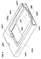
- FIG. 2 shows an exemplary heater unit
- FIG. 3 shows an exemplary heater chip
- FIG. 4 shows a cross-section of a microfluidic cartridge, when in contact with a heater substrate
- FIGS. 5A and 5B show a plan view of heater circuitry adjacent to a PCR reaction chamber
- FIG. 5C shows thermal images of heater circuitry in operation
- FIG. 6A shows an exemplary multi-lane cartridge
- FIG. 6B shows a portion of an exemplary multi-lane cartridge
- FIG. 7 shows a plan view of an exemplary multi-lane microfluidic cartridge
- FIG. 8 shows an exemplary microfluidic network in a lane of a multi-lane cartridge
- FIGS. 9A-C show a layer structure of an exemplary microfluidic cartridge
- FIGS. 10A-C show exemplary configurations of microfluidic valves
- FIG. 11 shows an exemplary highly-multiplexed microfluidic cartridge
- FIGS. 12-15 show various aspects of exemplary highly multiplexed microfluidic cartridges.
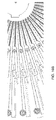
- FIGS. 16A-C show various aspects of a radially configured highly multiplexed microfluidic cartridge.
- FIGS. 17A-17C shows various cut-away sections that can be used to improve cooling rates during PCR thermal cycling
- FIG. 18 shows a plot of temperature against time during a PCR process, as performed on a microfluidic cartridge as described herein;
- FIG. 19 shows an exemplary layout for electronics and software components, as further described herein;
- FIG. 20 shows an exemplary apparatus, a microfluidic cartridge, and a read head, as further described herein;
- FIGS. 21-23 show positioning of a cartridge in an exemplary apparatus
- FIGS. 24 and 25 show removal of a heater unit from an exemplary apparatus
- FIGS. 26A and 26B show an exemplary heater unit and heater substrate
- FIGS. 27-29 show an exemplary heater substrate and heater unit
- FIGS. 30A-30C show an exemplary heater configuration to heat a PCR chamber
- FIGS. 31A-31F show aspects of heater element fine structure.
- the present technology comprises a heater unit that is configured to apply heat selectively to a microfluidic substrate for the purpose of carrying out an amplification, such as by PCR, of one or more polynucleotides from one or more samples present in the substrate.
- an amplification such as by PCR
- any other form of polynucleotide amplification is intended to be understood.
- apply heat selectively is meant that the heat may be applied to one or more specific locations on the cartridge and at controlled times. Thus certain locations may be heated contemporaneously, such as simultaneously, and other locations may receive heat at different times from one another.
- the microfluidic substrate is designed so that it receives thermal energy from one or more heating elements present in the heater unit described herein when it is in thermal communication therewith.
- a substrate may be part of a cartridge.
- cartridge is meant a unit that may be disposable, or reusable in whole or in part, and that is configured to be used in conjunction with some other apparatus that has been suitably and complementarily configured to receive and operate on (such as deliver energy to via a heater module as described herein) the cartridge.
- An exemplary such cartridge is further described herein; additional embodiments of such a cartridge are found in U.S. patent application Ser. No. 11/940,310, entitled “Microfluidic Cartridge and Method of Making Same”, and filed on even date herewith, the specification of which is incorporated herein by reference.
- the heater unit may be part of an apparatus, configured to receive the cartridge, and comprising other features such as control circuitry, user interface, and detector, as well as still other features.
- An exemplary such apparatus is further described herein; additional embodiments of such an apparatus are found in U.S. patent application Ser. No. 11/985,577, entitled “Microfluidic System for Amplifying and Detecting Polynucleotides in Parallel”, and filed on even date herewith, the specification of which is incorporated herein by reference.
- microfluidic as used herein, is meant that volumes of sample, and/or reagent, and/or amplified polynucleotide are from about 0.1 ⁇ l to about 999 ⁇ l, such as from 1-100 ⁇ l, or from 2-25 ⁇ l.
- microfluidic means that various components and channels of the cartridge, as further described herein, are configured to accept, and/or retain, and/or facilitate passage of microfluidic volumes of sample, reagent, or amplified polynucleotide.
- One aspect of the present technology relates to a heater unit that is configured to apply heat selectively to a microfluidic substrate having two or more sample lanes arranged so that analyses can be carried out in two or more of the lanes in parallel, for example simultaneously, and wherein each lane is independently associated with a given sample.
- a sample lane as found in a microfluidic substrate that is heated by a heater unit herein, is an independently controllable set of elements by which a sample can be analyzed, for example by carrying out PCR on a sample in which the presence or absence of one or more polynucleotides is to be determined, according to methods described in, e.g., U.S. patent application Ser. No. 11/940,310, entitled “Microfluidic Cartridge and Method of Making Same”, and filed on even date herewith.
- a sample lane comprises at least a sample inlet, and a microfluidic network having one or more micro fluidic components, as further described herein.
- a sample lane of a microfluidic substrate can include a sample inlet port or valve, and a microfluidic network that comprises, in fluidic communication one or more components selected from the group consisting of: at least one thermally actuated valve, a bubble removal vent, at least one gate, at least one thermally actuated pump, a downstream thermally actuated valve, mixing channels, one or more positioning elements, and a PCR reaction chamber.
- the various components of the microfluidic network of each sample lane can be independently and selectively heated by the heater unit described herein.
- Channels of a microfluidic network in a lane of a substrate typically have at least one sub-millimeter cross-sectional dimension.
- channels of such a network may have a width and/or a depth of about 1 mm or less (e.g., about 750 microns or less, about 500 microns, or less, about 250 microns or less).
- the microfluidic network can be configured to couple heat from an external heat source provided by the heater unit described herein to a sample mixture comprising PCR reagent and neutralized polynucleotide sample under thermal cycling conditions suitable for creating PCR amplicons from the neutralized polynucleotide sample.
- a multi-lane substrate that is heated by a heater unit described herein is configured to accept a number of samples in series or in parallel, in particular embodiments 12 samples, wherein the samples include at least a first sample and a second sample, wherein the first sample and the second sample each contain one or more polynucleotides in a form suitable for amplification.
- the polynucleotides in question may be the same as, or different from one another, in different samples and hence in different lanes of the substrate.
- the substrate typically processes each sample by increasing the concentration of a polynucleotide to be determined and/or by reducing the concentration of inhibitors relative to the concentration of polynucleotide to be determined.
- FIG. 1 shows a schematic cross-sectional view of a part of an apparatus as described herein, showing input of sample into a microfluidic cartridge 100 via a pipette 10 (such as a disposable pipette that may be integrated into an automated dispensing hear 110 ) and an inlet 102 .
- Inlet 102 is preferably configured to receive a pipette or the bottom end of a PCR tube and thereby accept sample for analysis with minimum waste, and with minimum introduction of air.
- Cartridge 100 is disposed on top of and in contact with a heater substrate 140 .
- Read head 130 is positioned above cartridge 100 and a cover for optics 131 restricts the amount of ambient light that can be detected by the read head.
- Heater substrate 140 is part of a heater unit (not shown in its entirety in FIG. 1 ) that is disposed within an apparatus, as further described herein.
- Cartridge 120 is situated in a suitably configured receiving bay 112 .
- the contact heat source typically includes a plurality of contact heat sources, each configured at the receiving bay to be independently thermally coupled to a different distinct location in a micro fluidic cartridge received therein, whereby the distinct locations are independently heated.
- the contact heat sources can be configured to be in direct physical contact with one or more distinct locations of a micro fluidic cartridge received in the bay.
- each contact source heater can be configured to heat a distinct location having an average diameter in 2 dimensions from about 1 millimeter (mm) to about 15 mm (typically about 1 mm to about 10 mm), or a distinct location having a surface area of between about 1 mm 2 about 225 mm 2 (typically between about 1 mm 2 and about 100 mm 2 , or in some embodiments between about 5 mm 2 and about 50 mm 2 ).
- Heater unit 2020 is shown in FIG. 2 .
- the unit is configured to deliver localized heat to various selected regions of a cartridge received in a receiving bay 2014 .
- Heater unit 2020 is configured to be disposed within a diagnostic apparatus during operation, as further described herein, and in certain embodiments is removable from that apparatus, for example to facilitate cleaning, or to permit reconfiguration of the heater circuitry.
- heater unit 2020 can be specific to particular designs of microfluidic networks and microfluidic substrate layouts.
- FIG. 3 illustrates heating operation of a heater substrate as further described herein.
- a schematic of a heater/sensor chip is shown at left.
- An actual heater/sensor chip bonded to a PCB is in the center of the FIG.,
- a thermal image of the same chip in operation showing highly localized heating (95° C.) in the PCR regions (yellow) is shown at right.
- FIG. 2 Shown in FIG. 2 is a heater unit having a recessed surface 2044 that provides a platform for supporting a microfluidic cartridge when in receiving bay 2014 .
- the cartridge rests directly on surface 2044 .
- Surface 2044 is shown as recessed, in FIG. 2 , but need not be so and, for example, may be raised or may be flush with the surrounding area of the heater unit.
- Surface 2044 is typically a layer of material that overlies a heater chip or board, or a heater substrate, that contains heater micro-circuitry configured to selectively and specifically heat regions of a microfluidic substrate, such as in a cartridge, in the receiving bay 2014 .
- Area 2044 is configured to accept a microfluidic cartridge in a single orientation. Therefore area 2044 can be equipped with a registration member such as a mechanical key that prevents a user from placing a cartridge into receiving bay 2014 in the wrong configuration. Shown in FIG. 2 as an exemplary mechanical key 2045 is a diagonally cutout corner of area 2044 into which a complementarily cutoff corner of a microfluidic cartridge fits.
- Other registration members are consistent with the heater unit described herein, for example, a feature engineered on one or more edges of a cartridge including but not limited to: several, such as two or more, cut-out corners, one or more notches cut into one or more edges of the cartridge; or one or more protrusions fabricated into one or more edges of the cartridge.
- Alternative registration members include one or more lugs or bumps engineered into an underside of a cartridge, complementary to one or more recessed sockets or holes in surface 2044 (not shown in the embodiment of FIG. 2 ).
- Alternative registration members include one or more recessed sockets or holes engineered into an underside of a cartridge, complementary to one or more lugs or bumps on surface 2044 .
- the pattern of features is such that the cartridge possesses at least one element of asymmetry so that it can only be inserted in a single orientation into the receiving bay.
- Cutaway 2048 permits a user to easily remove a cartridge from receiving bay 2014 after a processing run where, e.g., a user's thumb or finger when grabbing the top of the cartridge, is afforded comfort space by cutaway 2048 .
- Both cutaways 2042 and 2048 are shown as semicircular recesses in the embodiment of FIG. 2 , but it would be understood that they are not so limited in shape. Thus, rectangular, square, triangular, half-oval, contoured, and other shaped recesses are also consistent with a heater unit as described herein.
- the front of the heater unit is at the left of the figure.
- an electrical connection 2050 such as an RS-232 connection, that permits electrical signals to be directed to heaters located at specific regions of area 2044 during sample processing and analysis, as further described herein.
- an array of heat sources such as resistive heaters, that are configured to align with specified locations of a microfluidic cartridge properly inserted into the receiving bay.
- Surface 2044 is able to be cleaned periodically, for example with common cleaning agents (e.g., a 10% bleach solution), to ensure that any liquid spills that may occur during sample handling do not cause any short circuiting.
- cleaning agents e.g., a 10% bleach solution
- Such cleaning can be carried out frequently when the heater unit is disposed in a diagnostic apparatus, and less frequently but more thoroughly when the unit is removed.
- One or more air vents 2052 can be situated on one or more sides (such as front, rear, or flanking) or faces (such as top or bottom) of heater unit 2020 , to permit excess heat to escape, when heaters underneath receiving bay 2014 , are in operation.
- the configuration of air vents in FIG. 2 is exemplary and it would be understood that other numbers and shapes thereof are consistent with routine fabrication and use of a heater unit. For example, although 5 square air vents are shown, other numbers such as 1, 2, 3, 4, 6, 8, or 10 air vents are possible, arranged on one side, or spread over two or more sides and/or faces of the heater unit.
- air vents may be circular, rectangular, oval, triangular, polygonal, and having curved or squared vertices, or still other shapes, including irregular shapes.
- two or more vents need not be disposed in a line, parallel with one another and with an edge of the heater unit but may be disposed offset from one another.
- Heater unit 2020 may further comprise one or more guiding members 2047 that facilitate inserting the heater unit into an apparatus as further described herein, for an embodiment in which heater unit 2020 is removable by a user. Heater unit is advantageously removable because it permits system 2000 to be easily reconfigured for a different type of analysis, such as employing a different cartridge with a different registration member and/or microfluidic network, in conjunction with the same or a different sequence of processing operations. In other embodiments, heater unit 2020 is designed to be fixed and only removable, e.g., for cleaning, replacement, or maintenance, by the manufacturer or an authorized maintenance agent, and not routinely by the user. Guiding members 2047 may perform one or more roles of ensuring that the heater unit is aligned correctly in the apparatus, and ensuring that the heater unit makes a tight fit and does not significantly move during processing and analysis of a sample, or during transport of the apparatus.
- Guiding members shown in the embodiment of FIG. 2 are on either side of receiving bay 2044 and stretch along a substantial fraction of the length of unit 2020 , but such an arrangement of guiding members is exemplary.
- Other guiding members are consistent with use herein, and include but are not limited to other numbers of guiding members such as 1, 3, 4, 5, 6, or 8, and other positions thereof, including positioned in area 2051 of unit 2020 , and need not stretch along as much of the length of unit 2020 as shown in FIG. 2 , or may stretch along its entire length.
- Guiding members 2047 are shown having a non-constant thickness along their lengths. It is consistent herein that other guiding members may have essentially constant thickness along their lengths. At the end of the heater unit that is inserted into an apparatus, in the embodiment shown, the edges are beveled to facilitate proper placement.
- an optional region of fluorescent material such as optically fluorescent material 2049 , on area 2051 of heater unit 2020 .
- the region of fluorescent material is configured to be detected by a detection system further described herein.
- the region 2049 is used for verifying the state of optics in the detection system prior to sample processing and analysis and therefore acts as a control, or a standard.
- a lid of the apparatus in which the heater unit is disposed when in an open position, permits ambient light to reach region 2049 and thereby cause the fluorescent material to emit a characteristic frequency or spectrum of light that can be measured by the detector for, e.g., standardization or calibration purposes.
- region 2049 instead of relying on ambient light to cause the fluorescent material to fluoresce, light source from the detection system itself, such as one or more LED's, is used to shine on region 2049 .
- the region 2049 is therefore positioned to align with a position of a detector.
- Region 2049 is shown as rectangular, but may be configured in other shapes such as square, circular, elliptical, triangular, polygonal, and having curved or squared vertices. It is also to be understood that the region 2049 may be situated at other places on the heater unit 2020 , according to convenience and in order to be complementary to the detection system deployed.
- heater/sensor unit 2020 can include, for example, a multiplexing function in a discrete multiplexing circuit board (MUX board), one or more heaters (e.g., a microheater), one or more temperature sensors (optionally combined together as a single heater/sensor unit with one or more respective microheaters, e.g., as photolithographically fabricated on fused silica substrates).
- MUX board discrete multiplexing circuit board
- heaters e.g., a microheater
- temperature sensors optionally combined together as a single heater/sensor unit with one or more respective microheaters, e.g., as photolithographically fabricated on fused silica substrates.
- the micro-heaters can provide thermal energy that can actuate various microfluidic components on a suitably positioned microfluidic cartridge.
- a sensor e.g., as a resistive temperature detector (RTD)
- RTD resistive temperature detector
- One or more microheaters can be aligned with corresponding microfluidic components (e.g., valves, pumps, gates, reaction chambers) to be heated on a suitably positioned microfluidic cartridge.
- a microheater can be designed to be slightly bigger than the corresponding microfluidic component(s) on the microfluidic cartridge so that even though the cartridge may be slightly misaligned, such as off-centered, from the heater, the individual components can be heated effectively.
- the microfluidic substrates described herein are configured to accept heat from a contact heat source, such as found in a heater unit described herein.
- the heater unit typically comprises a heater board or heater chip that is configured to deliver heat to specific regions of the microfluidic substrate, including but not limited to one or more microfluidic components, at specific times.
- the heat source is configured so that particular heating elements are situated adjacent to specific components of the microfluidic network on the substrate.
- the apparatus uniformly controls the heating of a region of a microfluidic network.
- multiple heaters can be configured to simultaneously and uniformly heat a region, such as the PCR reaction chamber, of the microfluidic substrate.
- the term heater unit, as used herein, may be used interchangeably to describe either the heater board or an item such as shown in FIG. 2 .
- FIG. 4 shows a cross-sectional view of an exemplary microfluidic cartridge to show relative location of PCR channel in relation to various heaters when the cartridge is placed in the instrument.
- the view in FIG. 4 is also referred to as a sectional-isometric view of the cartridge lying over the heater wafer.
- a window 903 above the PCR channel in the cartridge is shown in perspective view.
- PCR channel 901 (for example, 150 ⁇ deep ⁇ 700 ⁇ wide), is shown in an upper layer of the cartridge.
- a laminate layer 905 of the cartridge (for example, 125 ⁇ thick) is directly under the PCR channel 901 .
- an optional further layer of thermal interface laminate 907 on the cartridge lies directly under the laminate layer 905 .
- Heaters 909 , 911 are situated in a heater substrate layer 913 directly under the thermal interface laminate.
- the heaters are photolithographically defined and etched metal layers of gold (typically about 3,000 ⁇ thick). Layers of 400 ⁇ of TiW are deposited on top and bottom of the gold layer to serve as an adhesion layer.
- the substrate used is glass, fused silica or quartz wafer having a thickness of 0.4 mm, 0.5 mm, 0.7 mm, or 1 mm.
- a thin electrically-insulative layer of 2 ⁇ m silicon oxide serves as an insulative layer on top of the metal layer. Additional thin electrically insulative layers such as 2-4 g/m of Parylene may also be deposited on top of the silicon oxide surface.
- Two long heaters 909 and 911 as further described herein, run alongside the PCR channel.
- FIGS. 5A and 5B an exemplary set of heaters configured to heat, cyclically, PCR reaction chamber 1001 is shown. It is to be understood that heater configurations to actuate other regions of a microfluidic cartridge such as other gates, valves, and actuators, may be designed and deployed according to similar principles to those governing the heaters shown in FIGS. 5A and 5B .
- An exemplary PCR reaction chamber 1001 in a microfluidic substrate is configured with a long side and a short side, each with an associated heating element.
- a PCR reaction chamber may also be referred to as a PCR reactor, herein, and the region of a cartridge in which the reaction chamber is situated may be called a zone.
- the heater substrate therefore preferably includes four heaters disposed along the sides of, and configured to heat, a given PCR reaction chamber, as shown in the exemplary embodiment of FIG. 5A : long top heater 1005 , long bottom heater 1003 , short left heater 1007 , and short right heater 1009 .
- the small gap between long top heater 1005 and long bottom heater 1003 results in a negligible temperature gradient (less than 1° C. difference across the width of the PCR channel at any point along the length of the PCR reaction chamber) and therefore an effectively uniform temperature throughout the PCR reaction chamber.
- the heaters on the short edges of the PCR reactor provide heat to counteract the gradient created by the two long heaters from the center of the reactor to the edge of the reactor.
- a ‘long’ side of the reaction zone can be configured to be heated by two or more heaters.
- Specific orientations and configurations of heaters are used to create uniform zones of heating even on substrates having poor thermal conductivity because the poor thermal conductivity of glass, or quartz, polyimide, FR4, ceramic, or fused silica substrates is utilized to help in the independent operation of various microfluidic components such as valves and independent operation of the various PCR lanes.
- the principles underlying the configuration of heaters around a PCR reaction zone are similarly applicable to the arrangement of heaters adjacent to other components of the microfluidic cartridge, such as actuators, valves, and gates.
- each heater has an associated temperature sensor.
- a single temperature sensor 1011 is used for both long heaters.
- a temperature sensor 1013 for short left heater, and a temperature sensor 1015 for short right heater are also shown.
- the temperature sensor in the middle of the reactor is used to provide feedback and control the amount of power supplied to the two long heaters, whereas each of the short heaters has a dedicated temperature sensor placed adjacent to it in order to control it.
- temperature sensors are preferably configured to transmit information about temperature in their vicinity to a processor in the apparatus at such times as the heaters are not receiving current that causes them to heat. This can be achieved with appropriate control of current cycles.
- each of the four heaters may be designed to have an appropriate wattage, and connect the four heaters in series or in parallel to reduce the number of electronically-controllable elements from four to just one, thereby reducing the burden on the associated electronic circuitry.
- FIG. 5B shows expanded views of heaters and temperature sensors used in conjunction with a PCR reaction chamber of FIG. 5A .
- Temperature sensors 1001 and 1013 are designed to have a room temperature resistance of approximately 200-300 ohms. This value of resistance is determined by controlling the thickness of the metal layer deposited (e.g., a sandwich of 400 ⁇ TiW/3,000 ⁇ Au/400 ⁇ TiW), and etching the winding metal line to have a width of approximately 10-25 ⁇ m and 20-40 mm length.
- the use of metal in this layer gives it a temperature coefficient of resistivity of the order of 0.5-20° C./ohms, preferably in the range of 1.5-3° C./ohms. Measuring the resistance at higher temperatures enables determination of the exact temperature of the location of these sensors.
- the configuration for uniform heating, shown in FIG. 5A for a single PCR reaction chamber, can also be applied to a multi-lane PCR cartridge in which multiple independent PCR reactions occur.
- FIG. 5C shows thermal images, from the top surface of a microfluidic cartridge when heated by heaters configured as in FIGS. 5A and 5B , when each heater in turn is activated, as follows: (A): Long Top only; (B) Long Bottom only; (C) Short Left only; (D) Short Right only; and (E) All Four Heaters on.
- Panel (F) shows a view of the reaction chamber and heaters on the same scale as the other image panels in FIG. 5C . Also shown in the figure is a temperature bar.
- the multi-sample cartridge comprises at least a first microfluidic network and a second microfluidic network, adjacent to one another, wherein each of the first microfluidic network and the second microfluidic network is as elsewhere described herein, and wherein the first microfluidic network accepts the first sample, and wherein the second microfluidic network accepts the second sample.
- FIG. 6A shows a perspective view of a portion of an exemplary microfluidic cartridge 200 for use with a heater unit described herein.
- FIG. 6B shows a close-up view of a portion of the cartridge 200 of FIG. 6A illustrating various representative components.
- the cartridge 200 may be referred to as a multi-lane PCR cartridge with dedicated sample inlets 202 .
- sample inlet 202 is configured to accept a liquid transfer member (not shown) such as a syringe, a pipette, or a PCR tube containing a PCR ready sample. More than one inlet 202 is shown in FIGS. 6A , 6 B, wherein one inlet operates in conjunction with a single sample lane.
- the multi-sample cartridge has a size substantially the same as that of a 96-well plate as is customarily used in the art.
- the cartridge may be used with plate handlers used elsewhere in the art.
- sample inlets of adjacent lanes are reasonably spaced apart from one another to prevent any contamination of one sample inlet from another sample when a user introduces a sample into any one cartridge.
- the sample inlets are configured so as to prevent subsequent inadvertent introduction of sample into a given lane after a sample has already been introduced into that lane.
- the multi-sample cartridge is designed so that a spacing between the centroids of sample inlets is 9 mm, which is an industry-recognized standard.
- a spacing between the centroids of sample inlets is 9 mm, which is an industry-recognized standard.
- the center-to-center distance between inlet holes in the cartridge that accept samples from PCR tubes, as further described herein is 9 mm.
- the inlet holes are manufactured conical in shape with an appropriate conical angle so that industry-standard pipette tips (2 ⁇ l, 20 ⁇ l, 200 ⁇ l, volumes, etc.) fit snugly.
- the apparatus herein may be adapted to suit other, later-arising, industry standards not otherwise described herein.
- the reactor 210 is a microfluidic channel that is heated through a series of cycles to carry out amplification of nucleotides in the sample, as further described herein. Both valves 204 and 206 are closed prior to thermocycling to prevent any evaporation of liquid, bubble generation, or movement of fluid from the PCR reactor. End vent 214 prevents a user from introducing any excess amount of liquid into the microfluidic cartridge, as well as playing a role of containing any sample from spilling over to unintended parts of the cartridge. A user may input sample volumes as small as an amount to fill from the bubble removal vent to the middle of the microreactor, or up to valve 204 or beyond valve 204 .
- microvalves prevents both loss of liquid or vapor thereby enabling even a partially filled reactor to successfully complete a PCR thermocycling reaction.
- the application of pressure to contact the cartridge to the heater unit assists in achieving better thermal contact between the heater and the heat-receivable parts of the cartridge, and also prevents the bottom laminate structure from expanding, as would happen if the PCR channel was partially filled with liquid and the entrapped air would be thermally expanded during thermocycling.
- FIGS. 9A-C show various views of an exemplary microfluidic cartridge as further described herein.
- FIG. 9A shows an exploded view
- FIG. 9B shows a perspective view
- FIG. 9C shows a cross-sectional view.
- an exemplary microfluidic cartridge 200 includes first 220 , second 222 , third 224 , fourth 226 , and fifth layers 228 , 230 (as shown) that enclose a microfluidic network having various components configured to process multiple samples in parallel that include one or more polynucleotides to be determined.
- Microfluidic cartridge 200 can be fabricated as desired, for example, according to methods described in U.S. patent application Ser. No. 11/940,310, entitled “Microfluidic Cartridge and Method of Making Same” and filed on even date herewith.
- the microfluidic cartridge layer includes a layer 228 , 230 of polypropylene or other plastic label with pressure sensitive adhesive (typically between about 50 and 150 microns thick) configured to seal the wax loading holes of the valves, trap air used for valve actuation, and serve as a location for operator markings.
- this layer is shown in two separate pieces, 228 , 230 , though it would be understood by one of ordinary skill in the art that a single piece layer would be appropriate.
- a force member on the apparatus can compress the compliant label of the cartridge. This can cause the bottom of the cartridge to be pressed down against the microheater substrate present in the heater unit. Springs, for example, present in the force member can deliver, for example approximately 50 lb of pressure to generate a minimum pressure, for example 2 psi over the entire cartridge bottom.
- the cartridge underside can have a layer of mechanically compliant heat transfer laminate that can enable thermal contact between the microfluidic substrate and the microheater substrate of the heater unit.
- a minimal pressure of 1 psi can be employed for reliable operation of the thermal valves, gate and pumps present in the microfluidic cartridge.
- Table 1 outlines volumes, pumping pressures, and operation times associated with various components of a microfluidic cartridge.
- a valve (sometimes referred to herein as a microvalve) is a component in communication with a channel, such that the valve has a normally open state allowing material to pass along a channel from a position on one side of the valve (e.g., upstream of the valve) to a position on the other side of the valve (e.g., downstream of the valve).
- the valve Upon actuation of the valve, the valve transitions to a closed state that prevents material from passing along the channel from one side of the valve to the other.
- a valve can include a mass of a thermally responsive substance (TRS) that is relatively immobile at a first temperature and more mobile at a second temperature.
- TRS thermally responsive substance
- the first and second temperatures are insufficiently high to damage materials, such as polymer layers of a microfluidic cartridge in which the valve is situated.
- a mass of TRS can be an essentially solid mass or an agglomeration of smaller particles that cooperate to obstruct the passage.
- TRS's include a eutectic alloy (e.g., a solder), wax (e.g., an olefin), polymers, plastics, and combinations thereof.
- the second temperature is less than about 90° C. and the first temperature is less than the second temperature (e.g., about 70° C. or less).
- a chamber is in gaseous communication with the mass of TRS.
- Embodiments of the microfluidic substrate described herein may be constructed that have high-density microfluidic circuitry on a single substrate that thereby permit processing of multiple samples in parallel, or in sequence, on a single cartridge.
- Preferred numbers of such multiple samples include 24, 36, 40, 48, 50, 60, 64, 72, 80, 84, 96, and 100, but it would be understood that still other numbers are consistent with the technology herein, where deemed convenient and practical.
- microfluidic substrates and cartridges described herein are not to be limited to rectangular shapes, but can include cartridges having circular, elliptical, triangular, rhombohedral, square, and other shapes. Such shapes may also be adapted to include some irregularity, such as a cut-out, to facilitate exact placement of a cartridge in a complementary apparatus as further described herein.
- a highly multiplexed cartridge has 48 sample lanes, and permits independent control of each valve in each lane by suitably configured heater circuitry, with 2 banks of thermocycling protocols per lane, as shown in FIG. 11 .
- the heaters (shown superimposed on the lanes) are arranged in three arrays. The heaters are themselves disposed within one or more substrates. Heater arrays 502 , 508 in two separate glass regions only apply heat to valves in the microfluidic networks in each lane. Because of the low thermal conductivity of glass, the individual valves may be heated separately from one another. This permits samples to be loaded into the cartridge at different times, and passed to the PCR reaction chambers independently of one another.
- the PCR heaters 504 , 506 are mounted on a silicon substrate—and are not readily heated individually, but thereby permit batch processing of PCR samples, where multiple samples from different lanes are amplified by the same set of heating/cooling cycles. It is preferable for the PCR heaters to be arranged in 2 banks (the heater arrays on the left 506 and right 508 are not in electrical communication with one another), thereby permitting a separate degree of sample control.
- FIG. 12 shows a representative 48-sample cartridge compatible with the heater arrays of FIG. 11 , and having a configuration of inlets different to that depicted on cartridges herein.
- the inlet configuration is exemplary and has been designed to maximize efficiency of space usage on the cartridge.
- the inlet configuration can be compatible with an automatic pipetting machine that has dispensing heads situated at a 9 mm spacing. For example, such a machine having 4 heads can load 4 inlets at once, in 12 discrete steps, for the cartridge of FIG. 12 .
- Other configurations of inlets though not explicitly described or depicted are compatible with the technology described herein.
- FIG. 13 shows, in close up, an exemplary spacing of valves and channels in adjacent lanes of a multi-sample microfluidic cartridge, for example as shown in FIG. 9 .
- FIGS. 14 and 15 show close-ups of, respectively, heater arrays compatible with, and inlets on the exemplary cartridge shown in FIG. 9 .
- FIGS. 16A and 16B show various views of an embodiment of a radially-configured highly-multiplexed cartridge, having a number of inlets, microfluidic lanes, valves and PCR reaction chambers.
- FIG. 16C shows an array of heater elements compatible with the cartridge layout of FIG. 16A .
- a number of thermal cycles are carried out.
- the cooling between each application of heat is preferably as rapid as possible.
- Improved rate of cooling can be achieved with various modifications to the heating substrate, as shown in FIGS. 17A-17C .
- FIG. 17A One way to achieve rapid cooling is to cutaway portions of the microfluidic cartridge substrate, as shown in FIG. 17A .
- the upper panel of FIG. 17A is a cross-section of an exemplary microfluidic cartridge taken along the dashed line A-A′ as marked on the lower panel of FIG. 17A .
- PCR reaction chamber 901 and representative heaters 1003 are shown.
- two cutaway portions one of which labeled 1201 , that are situated alongside the heaters that are positioned along the long side of the PCR reaction chamber. Cutaway portions such as 1201 reduce the thermal mass of the cartridge, and also permit air to circulate within the cutaway portions. Both of these aspects permit heat to be conducted away quickly from the immediate vicinity of the PCR reaction chamber.
- Other configurations of cutouts, such as in shape, position, and number, are consistent with the present technology.
- cutouts such as in shape, position, and number, are consistent with the present technology. These cutouts may be created by a method selected from: selective etching using wet etching processes, deep reactive ion etching, selective etching using CO 2 laser or femtosecond laser (to prevent surface cracks or stress near the surface), selective mechanical drilling, selective ultrasonic drilling, or selective abrasive particle blasting. Care has to be taken to maintain mechanically integrity of the heater while reducing as much material as possible.
- FIG. 17C shows a combination of cutouts and use of ambient air cooling to increase the cooling rate during the cooling stage of thermocycling.
- a substantial amount of cooling happens by convective loss from the bottom surface of the heater surface to ambient air.
- the driving force for this convective loss is the differential in temperatures between the glass surface and the air temperature.
- the rate of cooling can be increased.
- the convective heat loss may also be increased by keeping the air at a velocity higher than zero.
- thermal cycling performance obtained with a configuration as described herein is shown in FIG. 18 for a protocol that is set to heat up to 92° C., and stay there for 1 second, then cool to 62° C., and stay for 10 seconds.
- Cycle time is about 29 seconds, with 8 seconds required to heat from 62° C. and stabilize at 92° C., and 10 seconds required to cool from 92° C., and stabilize at 62° C.
- Another aspect of the heater unit described herein relates to a control of heat within the system and its components.
- the method leads to a greater energy efficiency of the apparatus described herein, because not all heaters are heating at the same time, and a given heater is receiving current for only part of the time.
- the heating of microfluidic components is controlled by passing currents through suitably configured microfabricated heaters.
- the heating can be further controlled by periodically turning the current on and off with varying pulse width modulation (PWM), wherein pulse width modulation refers to the on-time/off-time ratio for the current.
- PWM pulse width modulation
- the current can be supplied by connecting a microfabricated heater to a high voltage source (for example, 30 V), which can be gated by the PWM signal.
- the device includes 48 PWM signal generators. Operation of a PWM generator includes generating a signal with a chosen, programmable, period (the end count) and a particular granularity.
- the signal can be 4000 ⁇ s (micro-seconds) with a granularity of 1 ⁇ s, in which case the PWM generator can maintain a counter beginning at zero and advancing in increments of 1 ⁇ s until it reaches 4000 ⁇ s, when it returns to zero.
- the amount of heat produced can be adjusted by adjusting the end count.
- a high end count corresponds to a greater length of time during which the microfabricated heater receives current and therefore a greater amount of heat produced.
- the granularity and signal width can take values other than those provided here without departing from the principles described herein.
- FIG. 18 illustrates exemplary electronics architecture modules for operating a heater unit and diagnostic apparatus. It would be understood by one of ordinary skill in the art that other configurations of electronics components are consistent with operation of the apparatus as described herein.
- the electronics architecture is distributed across two components of the apparatus: the Analyzer 2100 and a Heater unit 2102 .
- the Analyzer apparatus as further described herein contains, for example, an Optical Detection Unit 2108 , a Control Board 2114 , a Backplane 2112 , and a LCD Touchscreen 2110 .
- the Control Board includes a Card Engine 2116 further described herein, and Compact Flash memory 2118 , as well as other components.
- the Heater Assembly includes a Heater Board 2104 and a Heater Mux Board 2106 , both further described herein.
- the Card Engine electronics module 2116 is a commercial, off the shelf “single board computer” containing a processor, memory, and flash memory for operating system storage.
- the optional LCD+Touchscreen electronics module 2110 is a user interface, for example, driven through a touchscreen, such as a 640 pixel by 480 pixel 8 inch LCD and 5-wire touchscreen.
- the Compact Flash electronics module 2118 is, for example, a 256 megabyte commercial, off the shelf, compact flash module for application and data storage.
- Other media are alternatively usable, such as USB-drive, smart media card, memory stick, and smart data-card having the same or other storage capacities.
- the Backplane electronics module 2112 is a point of connection for the removable heater assembly 2102 . Bare PC boards with two connectors are sufficient to provide the necessary level of connectivity.
- the Control Board electronics module 2114 supports peripherals to the Card Engine electronics module 2116 .
- the peripherals include such devices as a USB host+slave or hub, a USB CDROM interface, serial ports, and ethernet ports.
- the Control Board 2114 can include a power monitor with a dedicated processor.
- the Control Board may also include a real time clock.
- the Control Board may further include a speaker.
- the Control Board 2114 also includes a CPLD to provide SPI access to all other modules and programming access to all other modules.
- the Control Board includes a programmable high voltage power supply.
- the Control Board includes a Serial-Deserializer interface to the LCD+Touchscreen electronics module 2110 and to the Optical Detection Unit electronics module 2108 .
- the Control Board also includes module connectors.
- the optical detection unit electronics module 2108 contains a dedicated processor.
- the optical detection unit 2108 contains a serializer-deserializer interface.
- the optical detection unit 2108 contains LED drivers.
- the optical detection unit also contains high gain-low noise photodiode amplifiers.
- the optical detection unit can have power monitoring capability.
- the optical detection unit can also be remotely reprogrammable.
- the heater mux (‘multiplex’) board electronics module 2106 has 24 high-speed ADC, 24 precision current sources, and 96 optically isolated current drivers for heating.
- the heater mux board has the ability to time-multiplex heating/measurement.
- the heater mux board has multiplexer banks to multiplex inputs to ADC, and to multiplex current source outputs.
- the heater mux board has a FPGA with a soft processor core and SDRAM.
- the heater mux board has a Power Monitor with a dedicated processor.
- the Heater Mux Board can be remotely reprogrammable.
- control electronics can be spread over four different circuit board assemblies.
- MAIN board Can serve as the hub of the Analyzer control electronics and manages communication and control of the other various electronic sub-assemblies.
- the main board can also serve as the electrical and communications interface with the external world.
- An external power supply (12V DC/10A; UL certified) can be used to power the system.
- the unit can communicate via 5 USB ports, a serial port and an Ethernet port.
- the main board can incorporate several diagnostic/safety features to ensure safe and robust operation of the Analyzer.
- the MUX Board Upon instruction from the main board, the MUX board can perform all the functions typically used for accurate temperature control of the heaters and can coordinate the collection of fluorescence data from the detector board.
- LCD Board Can contain the typical control elements to light up the LCD panel and interpret the signals from the touch sensitive screen.
- the LCD/touch screen combination can serve as a mode of interaction with the user via a Graphical User Interface.
- Detector Board Can house typical control and processing circuitry that can be employed to collect, digitize, filter, and transmit the data from the fluorescence detection modules.
- Control Board Electronics Module executes, for example, Control Board Power Monitor software.
- the Card Engine electronics module executes an operating system, graphical user interface (GUI) software, an analyzer module, and an application program interface (api).
- GUI graphical user interface
- api application program interface
- the Optical Detection Unit electronics module executes an optics software module.
- the Heater Mux Board electronics module executes dedicated Heater Mux software, and Heater Mux Power Monitor software.
- Each of the separate instances of software can be modular and under a unified control of, for example, driver software.
- the exemplary electronics can use Linux, UNIX, Windows, or MacOS, including any version thereof, as the operating system.
- the operating system is preferably loaded with drivers for USB, Ethernet, LCD, touchscreen, and removable media devices such as compact flash. Miscellaneous programs for configuring the Ethernet interface, managing USB connections, and updating via CD-ROM can also be included.
- the analyzer module is the driver for specific hardware.
- the analyzer module provides access to the Heater Mux Module, the Optical Detection Unit, the Control Board Power Monitor, the Real Time Clock, the High Voltage Power Supply, and the LCD backlight.
- the analyzer module provides firmware programming access to the Control Board power monitor, the Optical Detection Unit, and the Heater Mux Module.
- the API provides uniform access to the analyzer module driver.
- the API is responsible for error trapping, and interrupt handling.
- the API is typically programmed to be thread safe.
- the Control Board Power Monitor software monitors power supplies, current and voltage, and signals error in case of a fault.
- the Optics Software performs fluorescence detection which is precisely timed to turn on/off of LED with synchronous digitization of the photodetector outputs.
- the Optics Software can also monitor power supply voltages.
- the Optics Software can also have self test ability.
- the Heater Mux Module software implements a “protocol player” which executes series of defined “steps” where each “step” can turn on sets of heaters to implement a desired microfluidic action.
- the Heater Mux Module software also has self test ability.
- the Heater Mux Module software contains a fuzzy logic temperature control algorithm.
- the Heater Mux Power Monitor software monitors voltage and current levels.
- the Heater Mux Power Monitor software can participate in self-test, synchronous, monitoring of the current levels while turning on different heaters.
- the present technology relates to a heater unit, cartridge, complementary apparatus, and related methods for amplifying, and carrying out diagnostic analyses on, nucleotides from biological samples.
- the technology includes a heater unit for heating selective regions of a microfluidic substrate, such as contained in a disposable or reusable microfluidic cartridge containing multiple sample lanes capable of processing samples in parallel as further described herein, and a reusable apparatus that is configured to selectively actuate on-cartridge operations, to detect and analyze the products of the PCR amplification in each of the lanes separately, in all simultaneously, or in groups simultaneously, and, optionally, can display the progression of analyses and results thereof on a graphical user interface.
- a reusable apparatus is further described in U.S.
- An Analyzer unit can contain typical hardware/firmware that can be employed to drive and monitor the operations on the cartridges as well as software to interpret, communicate and store the results.
- Typical components of the Analyzer can include: (a) Control Electronics (DAQ), (b) Heater/Sensor Unit, (c) Fluorescent Detection Module, (d) Mechanical Fixtures, (e) Software and (f) User Interface (LCD/Touch screen) (g) Peripherals (CD-ROM, USB/Serial/Ethernet communication ports, barcode scanner, optional keyboard).
- FIG. 20 shows a perspective view of an exemplary apparatus 100 consistent with those described herein, as well as various components thereof, such as exemplary cartridge 200 that contains multiple sample lanes, and exemplary read head 300 that contains detection apparatus for reading signals from cartridge 200 .
- the apparatus 100 of FIG. 20 is able to carry out real-time PCR on a number of samples in cartridge 200 simultaneously.
- the number of samples is 12 samples, as illustrated with exemplary cartridge 200 , though other numbers of samples such as 4, 8, 10, 16, 20, 24, 25, 30, 32, 36, 40, and 48 are within the scope of the present description.
- an apparatus includes: a receiving bay configured to selectively receive a microfluidic cartridge as described herein; at least one heat source thermally coupled to the receiving bay; and a processor coupled to the heat source, wherein the heat source is configured to selectively heat individual regions of individual sample lanes in the cartridge, and the processor is configured to control application of heat to the individual sample lanes, separately, in all simultaneously, or in groups simultaneously; at least one detector configured to detect one or more polynucleotides or a probe thereof in a sample in one or more of the individual sample lanes, separately or simultaneously; and a processor coupled to the detector to control the detector and to receive signals from the detector.
- the receiving bay is a portion of the apparatus that is configured to selectively receive the microfluidic cartridge.
- the receiving bay and the microfluidic cartridge can be complementary in shape so that the microfluidic cartridge is selectively received in, e.g., a single orientation.
- the microfluidic cartridge can have a registration member that fits into a complementary feature of the receiving bay.
- the registration member can be, for example, a cut-out on an edge of the cartridge, such as a corner that is cut-off, or one or more notches or grooves that are made on one or more of the sides in a distinctive pattern that prevents a cartridge from being loaded into the bay in more than one distinct orientation.
- the receiving bay can help a user to place the cartridge so that the apparatus can properly operate on the cartridge.
- the cartridge can be designed to be slightly smaller than the dimensions of the receiving bay, e.g., by approximately 200-300 microns, for easy placement and removal of the cartridge.
- the lower surface of the cartridge can have a layer of mechanically compliant heat transfer laminate that can enable thermal contact between the microfluidic substrate and the microheater substrate of the heater unit.
- a minimal pressure of 1 psi can be employed for reliable operation of the thermal valves, gates and pumps present in the microfluidic cartridge.
- the apparatus can further include a sensor coupled to the processor, the sensor configured to sense whether the microfluidic cartridge is selectively received.
- the processor can be programmable to operate the detector to detect one or more polynucleotides or a probe thereof in a microfluidic cartridge located in the receiving bay.
- the detector can be, for example, an optical detector.
- the detector can include a light source that selectively emits light in an absorption band of a fluorescent dye, and a light detector that selectively detects light in an emission band of the fluorescent dye, wherein the fluorescent dye corresponds to a fluorescent polynucleotide probe or a fragment thereof.
- the optical detector can include a bandpass-filtered diode that selectively emits light in the absorption band of the fluorescent dye and a bandpass filtered photodiode that selectively detects light in the emission band of the fluorescent dye; or for example, the optical detector can be configured to independently detect a plurality of fluorescent dyes having different fluorescent emission spectra, wherein each fluorescent dye corresponds to a fluorescent polynucleotide probe or a fragment thereof; or for example, the optical detector can be configured to independently detect a plurality of fluorescent dyes at a plurality of different locations on a microfluidic cartridge, wherein each fluorescent dye corresponds to a fluorescent polynucleotide probe or a fragment thereof in a different sample.
- the detector can also be configured to detect the presence or absence of sample in a PCR reaction chamber in a given sample lane, and to condition initiation of thermocycling upon affirmative detection of presence of the sample. Further description of suitably configured detectors are described in U.S. patent application Ser. No. 11/940,321, filed on Nov. 14, 2007 and entitled “Fluorescence Detector for Microfluidic Diagnostic System”, incorporated herein by reference.
- the various depictions therein show a heater substrate disposed underneath a microfluidic substrate, and a detector disposed on top of it, it would be understood that an inverted arrangement would work equally as well.
- the heater would be forced down onto the microfluidic substrate, making contact therewith, and the detector would be mounted underneath the substrate, disposed to collect light directed downwards towards it.
- the apparatus can further include an analysis port.
- the analysis port can be configured to allow an external sample analyzer to analyze a sample in the microfluidic cartridge.
- the analysis port can be a hole or window in the apparatus which can accept an optical detection probe that can analyze a sample or progress of PCR in situ in the microfluidic cartridge.
- the analysis port can be configured to direct a sample from the microfluidic cartridge to an external sample analyzer; for example, the analysis port can include a conduit in fluid communication with the microfluidic cartridge that directs a liquid sample containing an amplified polynucleotide to a chromatography apparatus, an optical spectrometer, a mass spectrometer, or the like.
- the heat source can be, for example, a heat source such as a resistive heater or network of resistive heaters.
- the at least one heat source can be a contact heat source selected from a resistive heater (or network thereof), a radiator, a fluidic heat exchanger and a Peltier device.
- the contact heat source can be configured at the receiving bay to be thermally coupled to one or more distinct locations of a microfluidic cartridge received in the receiving bay, whereby the distinct locations are selectively heated.
- the heat source is disposed in a heating unit that is configured to be removable from the apparatus, as further described herein.
- the apparatus can include a compliant layer at the contact heat source configured to thermally couple the contact heat source with at least a portion of a microfluidic cartridge received in the receiving bay.
- the compliant layer can have a thickness of between about 0.05 and about 2 millimeters and a Shore hardness of between about 25 and about 100.
- the apparatus can further include one or more force members configured to apply force to at least a portion of a microfluidic cartridge received in the receiving bay.
- the one or more force members are configured to apply force to thermally couple the at least one heat source to at least a portion of the microfluidic cartridge. The application of force is important to ensure consistent thermal contact between the heater wafer and the PCR reactor and microvalves in the microfluidic cartridge.
- the apparatus preferably also includes a processor microprocessor circuitry, in communication with, for example, the input device and a display, that accepts a user's instructions and controls analysis of samples.
- a processor microprocessor circuitry in communication with, for example, the input device and a display, that accepts a user's instructions and controls analysis of samples.
- the apparatus can further include at least one input device coupled to the processor, the input device being selected from the group consisting of a keyboard, a touch-sensitive surface, a microphone, and a mouse.
- the apparatus can further include at least one sample identifier coupled to the processor, the sample identifier being selected from an optical scanner such as an optical character reader, a bar code reader, or a radio frequency tag reader.
- the sample identifier can be a handheld bar code reader.
- the apparatus can further include at least one data storage medium coupled to the processor, the medium selected from: a hard disk drive, an optical disk drive, or one or more removable storage media such as a CD-R, CD-RW, USB-drive, or flash memory card.
- the apparatus can further include at least one output coupled to the processor, the output being selected from a display, a printer, and a speaker, the coupling being either directly through a directly dedicated printer cable, or wirelessly, or via a network connection.
- the apparatus further optionally comprises a display that communicates information to a user of the system. Such information includes but is not limited to: the current status of the system; progress of PCR thermocycling; and a warning message in case of malfunction of either system or cartridge.
- the display is preferably used in conjunction with an external input device as elsewhere described herein, through which a user may communicate instructions to apparatus 100 .
- a suitable input device may further comprise a reader of formatted electronic media, such as, but not limited to, a flash memory card, memory stick, USB-stick, CD, or floppy diskette.
- An input device may further comprise a security feature such as a fingerprint reader, retinal scanner, magnetic strip reader, or bar-code reader, for ensuring that a user of the system is in fact authorized to do so, according to pre-loaded identifying characteristics of authorized users.
- An input device may additionally—and simultaneously—function as an output device for writing data in connection with sample analysis. For example, if an input device is a reader of formatted electronic media, it may also be a writer of such media. Data that may be written to such media by such a device includes, but is not limited to, environmental information, such as temperature or humidity, pertaining to an analysis, as well as a diagnostic result, and identifying data for the sample in question.
- the apparatus may further include a computer network connection that permits extraction of data to a remote location, such as a personal computer, personal digital assistant, or network storage device such as computer server or disk farm.
- the network connection can be a communications interface selected from the group consisting of: a serial connection, a parallel connection, a wireless network connection, and a wired network connection such as an ethernet or cable connection, wherein the communications interface is in communication with at least the processor.
- the computer network connection may utilize, e.g., ethernet, firewire, or USB connectivity.
- the apparatus may further be configured to permit a user to e-mail results of an analysis directly to some other party, such as a healthcare provider, or a diagnostic facility, or a patient.
- Apparatus 100 may optionally comprise one or more stabilizing feet that cause the body of the device to be elevated above a surface on which system 100 is disposed, thereby permitting ventilation underneath system 100 , and also providing a user with an improved ability to lift system 100 .
- the heat sources are operated by an operating system, which operates the device during use.
- the operating system includes a processor (e.g., a computer) configured to actuate the heat sources according to a desired protocol.
- processors configured to operate microfluidic devices are described in, e.g., U.S. application Ser. No. 09/819,105, filed Mar. 28, 2001, which application is incorporated herein by reference.
- the computer program product can include one or more instructions to cause the system to: output an indicator of the placement of the microfluidic cartridge in the receiving bay; read a sample label or a microfluidic cartridge label; output directions for a user to input a sample identifier; output directions for a user to load a sample transfer member with the PCR-ready sample; output directions for a user to introduce the PCR-ready sample into the microfluidic cartridge; output directions for a user to place the microfluidic cartridge in the receiving bay; output directions for a user to close the lid to operate the force member; output directions for a user to pressurize the PCR-ready sample in the microfluidic cartridge by injecting the PCR-ready sample with a volume of air between about 0.5 mL and about 5 mL; and output status information for sample progress from one or more lanes of the cartridge.
- the computer program product can include one or more instructions to cause the system to: heat the PCR ready-sample under thermal cycling conditions suitable for creating PCR amplicons from the neutralized polynucleotide; contact the neutralized polynucleotide sample or a PCR amplicon thereof with at least one probe that is selective for a polynucleotide sequence; independently contact each of the neutralized polynucleotide sample and a negative control polynucleotide with the PCR reagent mixture under thermal cycling conditions suitable for independently creating PCR amplicons of the neutralized polynucleotide sample and PCR amplicons of the negative control polynucleotide; contact the neutralized polynucleotide sample or a PCR amplicon thereof and the negative control polynucleotide or a PCR amplicon thereof with at least one probe that is selective for a polynucleotide sequence; output a determination of the presence of a polynucleotide sequence in the biological
- the computer program product can include one or more instructions to cause the system to automatically conduct one or more of the steps of the method.
- This non-limiting example describes pictorially, various embodiments of an apparatus, showing incorporation of a heater unit and a microfluidic cartridge operated on by the heater unit.
- FIG. 21 shows an apparatus 1100 that includes a housing having a display output 1102 , an openable lid 1104 , and a bar code reader 1106 .
- the cartridge is positioned in a single orientation in a receiving bay under the lid, FIG. 22 .
- the lid of the apparatus can be closed to apply pressure to the cartridge, as shown in FIG. 23 .
- the unit currently weighs about 20 lbs. and is approximately 10′′ wide by 16′′ deep by 13′′ high.
- FIGS. 24 and 25 The heating stage of the apparatus can be removable for cleaning, maintenance, or to replace a custom heating stage for a particular microfluidic cartridge.
- FIGS. 24 and 25 also show how a heater unit is insertable and removable from a front access door to an analyzer apparatus.
- FIG. 26A shows an exploded view of an exemplary heater unit.
- the unit has a top cover and a bottom cover that together enclose a Mux board (control board), a pressure support layer, and insulator film, and a microthermal circuit on a PCB.
- the last of these is the heat source that selectively heats regions of a microfluidic substrate placed in contact therewith through the top cover.
- An exemplary heater substrate FIG. 26B , consists of a photo-lithographically processed glass wafer bonded to a standard 0.100′′ standard FR4 printed circuit board.
- the glass wafer is 0.5 mm thick and is cut into a rectangle the size of 3.5 ⁇ 4.25 inches.
- the glass substrate has numerous metal heaters and resistive temperature sensors photo-lithographically etched on the surface of the glass wafer.
- the substrate is aligned and bonded to the PCBoard using a compliant epoxy, ensuring flatness to within 2-3 mils over the surface of the wafer.
- the cured epoxy should withstand up to 120° C. for two hours minimum.
- wire bond pads of the size of approximately 1 mm ⁇ 0.25 mm, with exposed gold surfaces, are located along the two long edges of the wafer. These pads are wirebonded (ball-bonding) to corresponding pads on the PCB using 1.5 mil gold wires. Wire bonding is a threading process, standard in semiconductor FAB. Alternatively, a flip-chip method may be used, though such methods are more complicated and may warp the wafer because of thermal mismatch. Wire bonds should have good integrity and pass defined pull strength. The substrate is baked at 120° C. for two hours and then the wire bonds are encapsulated by a compliant epoxy that will protect the wirebonds but not damage the bonds even at 120° C.
- Encapsulant should not spill over pre-defined area around the wirebonds and should not be taller than a defined height. For example, instead of laying epoxy all over the substrate, lines (e.g., a hash pattern) of it are made so that epoxy cures and air escapes through side. Alternatively, a laminate fill (adhesive on both sides) can be used. Standard connectors are soldered to the PCB and then the unit is tested using a test set-up to ensure all heaters and sensors read the right resistance values.
- lines e.g., a hash pattern
- a laminate fill adheresive on both sides
- FIGS. 27-29 Pictures of an exemplary Mux board and assembled heater unit are shown in FIGS. 27-29 .
- the operation of a PWM generator can also include a programmable start count in addition to the aforementioned end count and granularity.
- multiple PWM generators can produce signals that can be selectively non-overlapping (e.g., by multiplexing the on-time of the various heaters) such that the current capacity of the high voltage power is not exceeded.
- Multiple heaters can be controlled by different PWM signal generators with varying start and end counts. The heaters can be divided into banks, whereby a bank defines a group of heaters of the same start count. For example, 36 PWM generators can be grouped into six different banks, each corresponding to a certain portion of the PWM cycle (500 ms for example).
- the end count for each PWM generator can be selectively programmed such that not more than six heaters, for example, will be on at any given time. Other numbers are consistent with operation herein.
- a portion of a PWM cycle can be selected as dead time (count 3000 to 4000 for example) during which no heating takes place and sensitive temperature sensing circuits can use this time to sense the temperature.
- the table below represents a PWM cycle for the foregoing example:
- FIGS. 30A-30C show an alternative heater circuit for heating a PCR chamber.
- FIG. 30A shows 7 lanes in a microfluidic substrate that have a PCR chamber that is bulbous in shape. An inlet, valves, and a vent hole are disposed on either side of the chamber.
- FIG. 30B shows layout of heater circuitry that can activate the valves as well as heat the PCR chamber.
- the inset shows a representative heater element for a PCR chamber. It is rounded in shape and has both a central and a circumferential heater/sensor element.
- FIG. 30C shows fine structure of the heating elements of both the central and the circumferential heater/sensors.
- the overall arrangement promotes rapid and uniform heating of the PCR reaction chamber.
- the narrower wires in the central heater/sensor ensures that the center of the chamber receives most heat.
- FIGS. 31A and 31B show, respectively, a set of heater arrays on a substrate, and a blown-up view of one representative array.
- various regions of the heater array are identified as A, B, and B′.
- FIGS. 31C and 31D show, respectively, detailed views of regions A and B.
- Region A is identified with sub-regions, S 1 -S 7 .
- FIGS. 31E and 31F show detailed views of sub-regions S 1 -S 7 . Attributes of the various sub-regions are as follows.
- S 1 , S 2 and S 3 are temperature sensors (S 2 and S 3 have similar design to one another); S 4 & S 5 are heaters, carry high currents during operation and have similar design to one another; S 6 & S 7 are heaters, carry high currents during operation and have similar design to one another. Since all the sensors and heaters are operated at the same time, there should be no shorting between metals of these sensors/heaters.
- the nominal width of metal in the heater elements is ⁇ 20 ⁇ m, and the nominal gap between adjacent portions of metal is ⁇ 10 ⁇ m. It has been found that sensor lines should optimally sense in at least 95% of the defined sensing area.
- the resistance of the sensors has to be within a defined range: lower values cause loss of sensitivity, resistors higher than certain values are not able to be read by some control circuitry. Pits no larger than half the width of the sensor line should be present on the oxide surface (10 ⁇ m). As the surface of the heater is mechanically pressed against by for example, a plastic microfluidic cartridge repeatedly, pits cause the metal to wear out over time.
- the nominal width of metal in the heater elements is ⁇ 60 ⁇ m, and the nominal gap between adjacent portions of metal is ⁇ 60 ⁇ m.
- the heaters should cover almost 100% of the heating area to provide pre-defined heating pattern. Since heaters carry high currents, pits will cause hot spots in the heater and will cause the heater to fail over repeated operation. Pits no larger than half the width of the heater line should be present on the oxide surface. As the surface of the heater is mechanically pressed against by for example, a plastic microfluidic cartridge repeatedly, pits cause the metal to wear out over time. The resistance of heater should be within a controlled range in order to carry desired current.
- the nominal width of metal in the heater elements is ⁇ 45 ⁇ m; the nominal gap is ⁇ 45 ⁇ m.
- the heater should cover almost 100% of the heating area to provide pre-defined heating pattern. Since heaters carry high currents, pits will cause hot spots in the heater and will cause the heater to fail over repeated operation. Pits no larger than half the width of the heater line ( ⁇ 25 ⁇ m) should be present on the oxide surface. As the surface of the heater is mechanically pressed against by for example, a plastic microfluidic cartridge repeatedly, pits cause the metal to wear out over time. The resistance of heater should be within a controlled range in order to carry desired current.
- the nominal width of metal in the heater elements is ⁇ 75 ⁇ m, and the nominal gap is ⁇ 125 ⁇ m.
- These sensors are also used as a heater and carry high currents during operation.
- the heater should cover almost 100% of the heating area to provide pre-defined heating pattern.
- the resistance of the sensors has to be within a defined range: lower values cause loss of sensitivity, resistors higher than certain values are not able to be read by some control circuitry. Pits no larger than half the width of the heater line ( ⁇ 40 ⁇ m) should be present on the oxide surface. Since heaters carry high currents, pits in the metal will cause hot spots in the heater and will cause the heater to fail over repeated operation. As the surface of the heater is mechanically pressed against by for example, a plastic microfluidic cartridge repeatedly, pits cause the metal to wear out over time.
- the resistance of heater should be within a controlled range in order to carry desired current.
Abstract
Description
| TABLE 1 | |||
| Pumping | Displacement | Time of | |
| Operation | Pressure | Volume | Operation |
| Moving valve wax plugs | ~1-2 psi | <1 μl | 5-15 seconds |
| Pump | Pump | ||
| Operation | Pump Used | Design | Actuation |
| Moving valve wax plugs | |
1 μl of | Heat trapped |
| pump | trapped air | air to | |
| ~70-90 C. | |||
| Start Count | End Count | Max End count | |
| |
| |
0 | 150 | 500 |
| |
0 | 220 | 500 |
| . . . | . . . | . . . | |
| PWM generator #6 | 0 | 376 | 500 |
| |
| PWM generator #7 | 500 | 704 | 1000 |
| PWM generator #8 | 500 | 676 | 1000 |
| . . . | . . . | . . . | . . . |
| PWM generator #12 | 500 | 780 | 1000 |
| Bank 3 |
| PWM generator #13 | 1000 | 1240 | 1500 |
| PWM generator #14 | 1000 | 1101 | 1500 |
| . . . | . . . | . . . | . . . |
| PWM generator #18 | 1000 | 1409 | 1500 |
| |
| PWM generator #19 | 1500 | 1679 | 2000 |
| |
1500 | 1989 | 2000 |
| . . . | . . . | . . . | . . . |
| PWM generator #24 | 1500 | 1502 | 2000 |
| Bank 5 |
| PWM generator #25 | 2000 | 2090 | 2500 |
| PWM generator #26 | 2000 | 2499 | 2500 |
| . . . | . . . | . . . | . . . |
| |
2000 | 2301 | 2500 |
| Bank 6 |
| |
2500 | 2569 | 3000 |
| PWM generator #32 | 2500 | 2790 | 3000 |
| . . . | . . . | . . . | . . . |
| |
2500 | 2678 | 3000 |
Claims (19)
Priority Applications (3)
| Application Number | Priority Date | Filing Date | Title |
|---|---|---|---|
| US11/940,315 US8088616B2 (en) | 2006-03-24 | 2007-11-14 | Heater unit for microfluidic diagnostic system |
| US13/341,477 US20160096178A9 (en) | 2006-03-24 | 2011-12-30 | Heater unit for microfluidic diagnostic system |
| US16/924,867 US20210121887A1 (en) | 2006-03-24 | 2020-07-09 | Heater unit for microfluidic diagnostic system |
Applications Claiming Priority (5)
| Application Number | Priority Date | Filing Date | Title |
|---|---|---|---|
| US78600706P | 2006-03-24 | 2006-03-24 | |
| US85928406P | 2006-11-14 | 2006-11-14 | |
| US11/728,964 US9040288B2 (en) | 2006-03-24 | 2007-03-26 | Integrated system for processing microfluidic samples, and method of using the same |
| US95943707P | 2007-07-13 | 2007-07-13 | |
| US11/940,315 US8088616B2 (en) | 2006-03-24 | 2007-11-14 | Heater unit for microfluidic diagnostic system |
Related Parent Applications (1)
| Application Number | Title | Priority Date | Filing Date |
|---|---|---|---|
| US11/728,964 Continuation-In-Part US9040288B2 (en) | 2006-03-24 | 2007-03-26 | Integrated system for processing microfluidic samples, and method of using the same |
Related Child Applications (1)
| Application Number | Title | Priority Date | Filing Date |
|---|---|---|---|
| US13/341,477 Continuation US20160096178A9 (en) | 2006-03-24 | 2011-12-30 | Heater unit for microfluidic diagnostic system |
Publications (2)
| Publication Number | Publication Date |
|---|---|
| US20080160601A1 US20080160601A1 (en) | 2008-07-03 |
| US8088616B2 true US8088616B2 (en) | 2012-01-03 |
Family
ID=39584533
Family Applications (3)
| Application Number | Title | Priority Date | Filing Date |
|---|---|---|---|
| US11/940,315 Active 2030-03-05 US8088616B2 (en) | 2006-03-24 | 2007-11-14 | Heater unit for microfluidic diagnostic system |
| US13/341,477 Abandoned US20160096178A9 (en) | 2006-03-24 | 2011-12-30 | Heater unit for microfluidic diagnostic system |
| US16/924,867 Abandoned US20210121887A1 (en) | 2006-03-24 | 2020-07-09 | Heater unit for microfluidic diagnostic system |
Family Applications After (2)
| Application Number | Title | Priority Date | Filing Date |
|---|---|---|---|
| US13/341,477 Abandoned US20160096178A9 (en) | 2006-03-24 | 2011-12-30 | Heater unit for microfluidic diagnostic system |
| US16/924,867 Abandoned US20210121887A1 (en) | 2006-03-24 | 2020-07-09 | Heater unit for microfluidic diagnostic system |
Country Status (1)
| Country | Link |
|---|---|
| US (3) | US8088616B2 (en) |
Cited By (59)
| Publication number | Priority date | Publication date | Assignee | Title |
|---|---|---|---|---|
| US20060166233A1 (en) * | 2004-05-03 | 2006-07-27 | Handylab, Inc. | Method and apparatus for processing polynucleotide-containing samples |
| US20070184547A1 (en) * | 2005-10-11 | 2007-08-09 | Kalyan Handique | Polynucleotide sample preparation device |
| US20070292941A1 (en) * | 2006-03-24 | 2007-12-20 | Handylab, Inc. | Integrated system for processing microfluidic samples, and method of using the same |
| US20080149840A1 (en) * | 2006-03-24 | 2008-06-26 | Kalyan Handique | Fluorescence Detector for Microfluidic Diagnostic System |
| US20080262213A1 (en) * | 2004-05-03 | 2008-10-23 | Betty Wu | Processing Polynucleotide-Containing Samples |
| US20090047713A1 (en) * | 2006-11-14 | 2009-02-19 | Kalyan Handique | Microfluidic Cartridge and Method of Making Same |
| US20090129978A1 (en) * | 2007-07-13 | 2009-05-21 | Handylab, Inc. | Reagent holder, and kits containing same |
| US20090134069A1 (en) * | 2007-07-13 | 2009-05-28 | Handylab, Inc. | Integrated Heater and Magnetic Separator |
| US20090221059A1 (en) * | 2007-07-13 | 2009-09-03 | Handylab, Inc. | Integrated apparatus for performing nucleic acid extraction and diagnostic testing on multiple biological samples |
| US20100009351A1 (en) * | 2008-07-11 | 2010-01-14 | Handylab, Inc. | Polynucleotide Capture Materials, and Method of Using Same |
| US20100197008A1 (en) * | 2003-07-31 | 2010-08-05 | Handylab, Inc. | Processing particle-containing samples |
| US20120160826A1 (en) * | 2006-03-24 | 2012-06-28 | Handylab, Inc. | Heater unit for microfluidic diagnostic system |
| US20130055793A1 (en) * | 2010-05-19 | 2013-03-07 | NEC Display Soulutions, Ltd. | Filter clogging detection apparatus |
| US8420015B2 (en) | 2001-03-28 | 2013-04-16 | Handylab, Inc. | Systems and methods for thermal actuation of microfluidic devices |
| US8440149B2 (en) | 2001-02-14 | 2013-05-14 | Handylab, Inc. | Heat-reduction methods and systems related to microfluidic devices |
| USD692162S1 (en) | 2011-09-30 | 2013-10-22 | Becton, Dickinson And Company | Single piece reagent holder |
| US8617905B2 (en) | 1995-09-15 | 2013-12-31 | The Regents Of The University Of Michigan | Thermal microvalves |
| US8703069B2 (en) | 2001-03-28 | 2014-04-22 | Handylab, Inc. | Moving microdroplets in a microfluidic device |
| US8768517B2 (en) | 2001-03-28 | 2014-07-01 | Handylab, Inc. | Methods and systems for control of microfluidic devices |
| US8895311B1 (en) | 2001-03-28 | 2014-11-25 | Handylab, Inc. | Methods and systems for control of general purpose microfluidic devices |
| US9050594B2 (en) | 2012-02-13 | 2015-06-09 | Neumodx Molecular, Inc. | System and method for processing and detecting nucleic acids |
| US9222954B2 (en) | 2011-09-30 | 2015-12-29 | Becton, Dickinson And Company | Unitized reagent strip |
| US20150375229A1 (en) * | 2014-06-30 | 2015-12-31 | Gnubio, Inc. | Floating thermal contact enabled pcr |
| US9238223B2 (en) | 2007-07-13 | 2016-01-19 | Handylab, Inc. | Microfluidic cartridge |
| US9259734B2 (en) | 2007-07-13 | 2016-02-16 | Handylab, Inc. | Integrated apparatus for performing nucleic acid extraction and diagnostic testing on multiple biological samples |
| US20160077031A1 (en) * | 2014-09-15 | 2016-03-17 | Sensirion Ag | Integrated chemical sensor chip |
| US9347586B2 (en) | 2007-07-13 | 2016-05-24 | Handylab, Inc. | Automated pipetting apparatus having a combined liquid pump and pipette head system |
| US9382532B2 (en) | 2012-10-25 | 2016-07-05 | Neumodx Molecular, Inc. | Method and materials for isolation of nucleic acid materials |
| US9562262B2 (en) | 2011-03-08 | 2017-02-07 | UNIVERSITé LAVAL | Fluidic centripetal device |
| US9604213B2 (en) | 2012-02-13 | 2017-03-28 | Neumodx Molecular, Inc. | System and method for processing and detecting nucleic acids |
| US9623415B2 (en) | 2014-12-31 | 2017-04-18 | Click Diagnostics, Inc. | Devices and methods for molecular diagnostic testing |
| USD787087S1 (en) | 2008-07-14 | 2017-05-16 | Handylab, Inc. | Housing |
| US9765389B2 (en) | 2011-04-15 | 2017-09-19 | Becton, Dickinson And Company | Scanning real-time microfluidic thermocycler and methods for synchronized thermocycling and scanning optical detection |
| USD799715S1 (en) | 2015-10-23 | 2017-10-10 | Gene POC, Inc. | Fluidic centripetal device |
| USD800331S1 (en) | 2016-06-29 | 2017-10-17 | Click Diagnostics, Inc. | Molecular diagnostic device |
| USD800913S1 (en) | 2016-06-30 | 2017-10-24 | Click Diagnostics, Inc. | Detection window for molecular diagnostic device |
| USD800914S1 (en) | 2016-06-30 | 2017-10-24 | Click Diagnostics, Inc. | Status indicator for molecular diagnostic device |
| USD804682S1 (en) * | 2015-08-10 | 2017-12-05 | Opko Diagnostics, Llc | Multi-layered sample cassette |
| US10093963B2 (en) | 2012-02-13 | 2018-10-09 | Neumodx Molecular, Inc. | System and method for processing biological samples |
| US10179910B2 (en) | 2007-07-13 | 2019-01-15 | Handylab, Inc. | Rack for sample tubes and reagent holders |
| US10195610B2 (en) | 2014-03-10 | 2019-02-05 | Click Diagnostics, Inc. | Cartridge-based thermocycler |
| USD849265S1 (en) * | 2017-04-21 | 2019-05-21 | Precision Nanosystems Inc | Microfluidic chip |
| US10675623B2 (en) | 2016-06-29 | 2020-06-09 | Visby Medical, Inc. | Devices and methods for the detection of molecules using a flow cell |
| US10822644B2 (en) | 2012-02-03 | 2020-11-03 | Becton, Dickinson And Company | External files for distribution of molecular diagnostic tests and determination of compatibility between tests |
| US10900066B2 (en) | 2006-03-24 | 2021-01-26 | Handylab, Inc. | Microfluidic system for amplifying and detecting polynucleotides in parallel |
| US10946384B2 (en) | 2013-09-11 | 2021-03-16 | Osaka University | Thermal convection generating chip, thermal convection generating device, and thermal convection generating method |
| US10987674B2 (en) | 2016-04-22 | 2021-04-27 | Visby Medical, Inc. | Printed circuit board heater for an amplification module |
| US11142785B2 (en) | 2006-03-24 | 2021-10-12 | Handylab, Inc. | Microfluidic system for amplifying and detecting polynucleotides in parallel |
| US11162130B2 (en) | 2017-11-09 | 2021-11-02 | Visby Medical, Inc. | Portable molecular diagnostic device and methods for the detection of target viruses |
| US11193119B2 (en) | 2016-05-11 | 2021-12-07 | Visby Medical, Inc. | Devices and methods for nucleic acid extraction |
| US11352675B2 (en) | 2020-01-03 | 2022-06-07 | Visby Medical, Inc. | Devices and methods for antibiotic susceptability testing |
| US11383236B2 (en) | 2017-11-10 | 2022-07-12 | Christopher Walker | Polymerase chain reaction using a microfluidic chip fabricated with printed circuit board techniques |
| US11453906B2 (en) | 2011-11-04 | 2022-09-27 | Handylab, Inc. | Multiplexed diagnostic detection apparatus and methods |
| US11485968B2 (en) | 2012-02-13 | 2022-11-01 | Neumodx Molecular, Inc. | Microfluidic cartridge for processing and detecting nucleic acids |
| WO2022235272A1 (en) * | 2021-05-07 | 2022-11-10 | Hewlett-Packard Development Company, L.P. | Overfill-tolerant microfluidic structures |
| USD979092S1 (en) | 2019-10-02 | 2023-02-21 | Becton, Dickinson And Company | Microfluidic cartridge |
| US11648561B2 (en) | 2012-02-13 | 2023-05-16 | Neumodx Molecular, Inc. | System and method for processing and detecting nucleic acids |
| US11806718B2 (en) | 2006-03-24 | 2023-11-07 | Handylab, Inc. | Fluorescence detector for microfluidic diagnostic system |
| US11952636B2 (en) | 2022-05-06 | 2024-04-09 | Visby Medical, Inc. | Devices and methods for antibiotic susceptibility testing |
Families Citing this family (26)
| Publication number | Priority date | Publication date | Assignee | Title |
|---|---|---|---|---|
| US6852287B2 (en) | 2001-09-12 | 2005-02-08 | Handylab, Inc. | Microfluidic devices having a reduced number of input and output connections |
| USD621060S1 (en) | 2008-07-14 | 2010-08-03 | Handylab, Inc. | Microfluidic cartridge |
| US20090136385A1 (en) | 2007-07-13 | 2009-05-28 | Handylab, Inc. | Reagent Tube |
| USD618820S1 (en) | 2008-07-11 | 2010-06-29 | Handylab, Inc. | Reagent holder |
| EP2689005A4 (en) * | 2011-03-23 | 2014-09-03 | California Inst Of Techn | System for performing polymerase chain reaction nucleic acid amplification |
| US9533308B2 (en) | 2012-02-10 | 2017-01-03 | California Institute Of Technology | PC board-based polymerase chain reaction systems, methods and materials |
| US20140322706A1 (en) | 2012-10-24 | 2014-10-30 | Jon Faiz Kayyem | Integrated multipelx target analysis |
| JP1628115S (en) | 2012-10-24 | 2019-04-01 | ||
| US9623409B2 (en) | 2013-03-11 | 2017-04-18 | Cue Inc. | Cartridges, kits, and methods for enhanced mixing for detection and quantification of analytes |
| CA3160098A1 (en) | 2013-03-11 | 2014-10-09 | Cue Health Inc. | Systems and methods for detection and quantification of analytes |
| US10545161B2 (en) | 2013-03-11 | 2020-01-28 | Cue Health Inc. | Systems and methods for detection and quantification of analytes |
| EP3520895A1 (en) | 2013-03-15 | 2019-08-07 | Genmark Diagnostics Inc. | Fluid container with cantilevered lance |
| US10793820B2 (en) * | 2013-04-30 | 2020-10-06 | Lawrence Livermore National Security, Llc | Miniaturized, automated in-vitro tissue bioreactor |
| US9498778B2 (en) | 2014-11-11 | 2016-11-22 | Genmark Diagnostics, Inc. | Instrument for processing cartridge for performing assays in a closed sample preparation and reaction system |
| USD881409S1 (en) | 2013-10-24 | 2020-04-14 | Genmark Diagnostics, Inc. | Biochip cartridge |
| USD745423S1 (en) | 2014-05-12 | 2015-12-15 | Cue Inc. | Automated analyzer test cartridge and sample collection device for analyte detection |
| CN106662374B (en) * | 2014-05-23 | 2020-08-25 | 莱尔德达勒姆有限公司 | Thermoelectric heating/cooling device including a resistive heater |
| US10005080B2 (en) | 2014-11-11 | 2018-06-26 | Genmark Diagnostics, Inc. | Instrument and cartridge for performing assays in a closed sample preparation and reaction system employing electrowetting fluid manipulation |
| US9598722B2 (en) | 2014-11-11 | 2017-03-21 | Genmark Diagnostics, Inc. | Cartridge for performing assays in a closed sample preparation and reaction system |
| CN112881730A (en) | 2015-07-17 | 2021-06-01 | 克忧健康公司 | Systems and methods for enhanced detection and analyte quantitation |
| WO2018140540A1 (en) | 2017-01-25 | 2018-08-02 | Cue Health Inc. | Systems and methods for enhanced detection and quantification of analytes |
| EP3357576B1 (en) * | 2017-02-06 | 2019-10-16 | Sharp Life Science (EU) Limited | Microfluidic device with multiple temperature zones |
| US10935149B2 (en) * | 2018-03-15 | 2021-03-02 | University Of Washington | Temperature-actuated valve, fluidic device, and related methods of use |
| GB201911386D0 (en) * | 2019-08-09 | 2019-09-25 | Stratec Se | Calibration tool for planar chip applications |
| USD954573S1 (en) * | 2019-11-06 | 2022-06-14 | Fluxergy, Llc | Test card |
| WO2022081955A1 (en) * | 2020-10-15 | 2022-04-21 | The Board Of Trustees Of The Leland Stanford Junior University | Method and system for ototopical delivery using nanoparticles for ear infection diagnosis and treatment |
Citations (459)
| Publication number | Priority date | Publication date | Assignee | Title |
|---|---|---|---|---|
| US1434314A (en) | 1921-08-04 | 1922-10-31 | Raich Anthony | Lunch pail |
| US1616419A (en) | 1925-04-03 | 1927-02-01 | Everlasting Valve Co | Automatic shut-off device for gas in case of fire |
| US1733401A (en) | 1928-03-29 | 1929-10-29 | Christman Matthias | Journal box |
| US3528449A (en) | 1968-02-27 | 1970-09-15 | Trw Inc | Fluid flow control apparatus |
| US3985649A (en) | 1974-11-25 | 1976-10-12 | Eddelman Roy T | Ferromagnetic separation process and material |
| US4018089A (en) | 1976-05-05 | 1977-04-19 | Beckman Instruments, Inc. | Fluid sampling apparatus |
| US4018652A (en) | 1976-01-09 | 1977-04-19 | Mcdonnell Douglas Corporation | Process and apparatus for ascertaining the concentration of microorganism in a water specimen |
| US4038192A (en) | 1973-12-03 | 1977-07-26 | International Biomedical Laboratories, Inc. | Device for exchange between fluids suitable for treatment of blood |
| US4055395A (en) | 1975-10-31 | 1977-10-25 | Hitachi, Ltd. | Analysis apparatus |
| USD249706S (en) | 1976-12-17 | 1978-09-26 | Eastman Kodak Company | Sample cup tray for chemical analysis of biological fluids |
| US4139005A (en) | 1977-09-01 | 1979-02-13 | Dickey Gilbert C | Safety release pipe cap |
| USD252157S (en) | 1977-04-14 | 1979-06-19 | Warner-Lambert Company | Diagnostic device for measuring biochemical characteristics of microorganisms and the like |
| USD252341S (en) | 1977-05-12 | 1979-07-10 | Ryder International Corporation | Testing tray |
| USD254687S (en) | 1979-01-25 | 1980-04-08 | Mcdonnell Douglas Corporation | Biochemical card for use with an automated microbial identification machine |
| US4212744A (en) | 1977-06-21 | 1980-07-15 | Asahi Medical Co., Ltd. | Haemodialyzer apparatus |
| USD261033S (en) | 1979-02-05 | 1981-09-29 | American Optical Corporation | Bilirubin concentration analyzer |
| USD261173S (en) | 1979-02-05 | 1981-10-06 | American Optical Corporation | Bilirubinometer |
| US4301412A (en) | 1979-10-29 | 1981-11-17 | United States Surgical Corporation | Liquid conductivity measuring system and sample cards therefor |
| JPS58212921A (en) | 1982-06-04 | 1983-12-10 | Aron Kasei Co Ltd | Molding method of plastic hollow product |
| US4439526A (en) | 1982-07-26 | 1984-03-27 | Eastman Kodak Company | Clustered ingress apertures for capillary transport devices and method of use |
| US4457329A (en) | 1981-12-04 | 1984-07-03 | Air Products And Chemicals, Inc. | Safety pressure regulator |
| US4466740A (en) | 1980-10-09 | 1984-08-21 | Olympus Optical Co., Ltd. | Particle agglutination analyzing plate |
| US4504582A (en) | 1982-07-20 | 1985-03-12 | Genex Corporation | Vermiculite as a carrier support for immobilized biological materials |
| US4522786A (en) | 1983-08-10 | 1985-06-11 | E. I. Du Pont De Nemours And Company | Multilayered test device for detecting analytes in liquid test samples |
| USD279817S (en) | 1982-07-19 | 1985-07-23 | Daryl Laboratories, Inc. | Immunoassay test slide |
| US4599315A (en) | 1983-09-13 | 1986-07-08 | University Of California Regents | Microdroplet test apparatus |
| US4612959A (en) | 1985-05-07 | 1986-09-23 | Mobil Oil Corporation | Valveless shut-off and transfer device |
| US4612873A (en) | 1982-09-02 | 1986-09-23 | Firma Andreas Hettich | Centrifuge chamber for cytodiagnostic investigation of epithelial cells contained in a sample |
| USD288478S (en) | 1984-06-21 | 1987-02-24 | Sentech Medical Corporation | Clinical chemistry analyzer |
| US4654127A (en) | 1984-04-11 | 1987-03-31 | Sentech Medical Corporation | Self-calibrating single-use sensing device for clinical chemistry and method of use |
| US4673657A (en) | 1983-08-26 | 1987-06-16 | The Regents Of The University Of California | Multiple assay card and system |
| US4683202A (en) | 1985-03-28 | 1987-07-28 | Cetus Corporation | Process for amplifying nucleic acid sequences |
| US4683195A (en) | 1986-01-30 | 1987-07-28 | Cetus Corporation | Process for amplifying, detecting, and/or-cloning nucleic acid sequences |
| USD292735S (en) | 1983-11-02 | 1987-11-10 | A/S Nunc | Tube for the immunological adsorption analysis |
| US4720374A (en) | 1985-07-22 | 1988-01-19 | E. I. Du Pont De Nemours And Company | Container having a sonication compartment |
| US4798693A (en) | 1984-04-26 | 1989-01-17 | Ngk Insulators, Ltd. | Method of manufacturing an electrochemical device |
| US4800022A (en) | 1985-03-13 | 1989-01-24 | Baxter International Inc. | Platelet collection system |
| USD302294S (en) | 1986-10-03 | 1989-07-18 | Biotrack, Inc. | Reagent cartridge for blood analysis |
| US4895650A (en) | 1988-02-25 | 1990-01-23 | Gen-Probe Incorporated | Magnetic separation rack for diagnostic assays |
| US4919829A (en) | 1988-12-30 | 1990-04-24 | The United States Of America As Represented By The Secretary Of Commerce | Aluminum hydroxides as solid lubricants |
| US4921809A (en) | 1987-09-29 | 1990-05-01 | Findley Adhesives, Inc. | Polymer coated solid matrices and use in immunoassays |
| US4946562A (en) | 1987-01-29 | 1990-08-07 | Medtest Systems, Inc. | Apparatus and methods for sensing fluid components |
| US4949742A (en) | 1989-04-26 | 1990-08-21 | Spectra-Physics, Inc. | Temperature operated gas valve |
| USD310413S (en) | 1987-12-17 | 1990-09-04 | Miles Inc. | Sample processor |
| US4963498A (en) | 1985-08-05 | 1990-10-16 | Biotrack | Capillary flow device |
| US4967950A (en) | 1989-10-31 | 1990-11-06 | International Business Machines Corporation | Soldering method |
| US4978622A (en) | 1986-06-23 | 1990-12-18 | Regents Of The University Of California | Cytophaga-derived immunopotentiator |
| US4978502A (en) | 1987-01-05 | 1990-12-18 | Dole Associates, Inc. | Immunoassay or diagnostic device and method of manufacture |
| US4989626A (en) | 1988-11-11 | 1991-02-05 | Hitachi, Ltd. | Apparatus for and method of controlling the opening and closing of channel for liquid |
| US5001417A (en) | 1987-06-01 | 1991-03-19 | Abbott Laboratories | Apparatus for measuring electrolytes utilizing optical signals related to the concentration of the electrolytes |
| US5004583A (en) | 1987-01-29 | 1991-04-02 | Medtest Systems, Inc. | Universal sensor cartridge for use with a universal analyzer for sensing components in a multicomponent fluid |
| US5048554A (en) | 1989-10-05 | 1991-09-17 | Ceodeux S.A. | Valve for a gas cylinder |
| US5053199A (en) | 1989-02-21 | 1991-10-01 | Boehringer Mannheim Corporation | Electronically readable information carrier |
| US5061336A (en) | 1989-05-01 | 1991-10-29 | Soane Technologies, Inc. | Gel casting method and apparatus |
| US5060823A (en) | 1988-09-15 | 1991-10-29 | Brandeis University | Sterile transfer system |
| US5064618A (en) | 1987-08-29 | 1991-11-12 | Thorn Emi Plc | Sensor arrangements |
| US5071531A (en) | 1989-05-01 | 1991-12-10 | Soane Technologies, Inc. | Casting of gradient gels |
| US5091328A (en) | 1989-11-21 | 1992-02-25 | National Semiconductor Corporation | Method of late programming MOS devices |
| USD324426S (en) | 1989-10-20 | 1992-03-03 | Pacific Biotech, Inc. | Reaction unit for use in analyzing biological fluids |
| US5096669A (en) | 1988-09-15 | 1992-03-17 | I-Stat Corporation | Disposable sensing device for real time fluid analysis |
| US5126002A (en) | 1989-09-29 | 1992-06-30 | Glory Kogyo Kabushiki Kaisha | Leaf paper bundling apparatus |
| US5126022A (en) | 1990-02-28 | 1992-06-30 | Soane Tecnologies, Inc. | Method and device for moving molecules by the application of a plurality of electrical fields |
| USD328135S (en) | 1990-01-12 | 1992-07-21 | Pacific Biotech, Inc. | Reaction unit for use in analyzing biological fluids |
| US5135872A (en) | 1989-04-28 | 1992-08-04 | Sangstat Medical Corporation | Matrix controlled method of delayed fluid delivery for assays |
| US5135627A (en) | 1990-10-15 | 1992-08-04 | Soane Technologies, Inc. | Mosaic microcolumns, slabs, and separation media for electrophoresis and chromatography |
| FR2672301A1 (en) | 1991-02-01 | 1992-08-07 | Larzul Daniel | Process and device for amplifying the number of a defined sequence of nucleic acid in a biological sample |
| USD328794S (en) | 1989-07-19 | 1992-08-18 | Pb Diagnostic Systems, Inc. | Diagnostic instrument or similar article |
| US5147606A (en) | 1990-08-06 | 1992-09-15 | Miles Inc. | Self-metering fluid analysis device |
| US5169512A (en) | 1988-04-08 | 1992-12-08 | Robert Bosch Gmbh | Planar polarographic probe for determining the λ value of gas mixtures |
| US5186339A (en) | 1990-07-20 | 1993-02-16 | Eastman Kodak Company | Device comprising a plurality of receptacles arranged in a single row for containers filled with a liquid |
| USD333522S (en) | 1991-07-23 | 1993-02-23 | P B Diagnostic Systems, Inc. | Sample tube holder |
| US5192507A (en) | 1987-06-05 | 1993-03-09 | Arthur D. Little, Inc. | Receptor-based biosensors |
| US5208163A (en) | 1990-08-06 | 1993-05-04 | Miles Inc. | Self-metering fluid analysis device |
| US5223226A (en) | 1992-04-14 | 1993-06-29 | Millipore Corporation | Insulated needle for forming an electrospray |
| USD338275S (en) | 1989-05-03 | 1993-08-10 | Bayer Diagnostics, GmbH | Combined clinical-chemical analyzer evaluation unit and work station |
| US5250263A (en) | 1990-11-01 | 1993-10-05 | Ciba-Geigy Corporation | Apparatus for processing or preparing liquid samples for chemical analysis |
| US5252743A (en) | 1989-11-13 | 1993-10-12 | Affymax Technologies N.V. | Spatially-addressable immobilization of anti-ligands on surfaces |
| US5256376A (en) | 1991-09-12 | 1993-10-26 | Medical Laboratory Automation, Inc. | Agglutination detection apparatus |
| US5275787A (en) | 1989-10-04 | 1994-01-04 | Canon Kabushiki Kaisha | Apparatus for separating or measuring particles to be examined in a sample fluid |
| US5282950A (en) | 1991-07-15 | 1994-02-01 | Boehringer Mannheim Gmbh | Electrochemical analysis system |
| US5296375A (en) | 1992-05-01 | 1994-03-22 | Trustees Of The University Of Pennsylvania | Mesoscale sperm handling devices |
| US5304477A (en) | 1991-07-08 | 1994-04-19 | Fuji Oil Company, Limited | Process for producing hard fats using 1,3-specific lipase and mixture of palmitic, lauric and behemic acids |
| US5304487A (en) | 1992-05-01 | 1994-04-19 | Trustees Of The University Of Pennsylvania | Fluid handling in mesoscale analytical devices |
| US5311996A (en) | 1993-01-05 | 1994-05-17 | Duffy Thomas J | Edge protector |
| US5311896A (en) | 1989-04-10 | 1994-05-17 | Niilo Kaartinen | Method for producing a heatable and refrigerable element for a system handling small quantities of liquid, and an element manufactured by the method |
| US5316727A (en) | 1989-09-08 | 1994-05-31 | Terumo Kabushiki Kaisha | Measuring apparatus |
| USD347478S (en) | 1991-11-05 | 1994-05-31 | Hybaid Ltd. | Laboratory instrument for handling bimolecular samples |
| US5327038A (en) | 1991-05-09 | 1994-07-05 | Rockwell International Corporation | Walking expansion actuator |
| US5339486A (en) | 1993-03-10 | 1994-08-23 | Persic Jr William V | Golf ball cleaner |
| USD351913S (en) | 1993-02-25 | 1994-10-25 | Diametrics Medical, Inc. | Disposable electrochemical measurement cartridge for a portable medical analyzer |
| US5364591A (en) | 1992-06-01 | 1994-11-15 | Eastman Kodak Company | Device for moving a target-bearing solid through a liquid for detection while being contained |
| US5372946A (en) | 1992-12-10 | 1994-12-13 | International Technidyne Corporation | Blood coagulation time test apparatus and method |
| US5374395A (en) | 1993-10-14 | 1994-12-20 | Amoco Corporation | Diagnostics instrument |
| US5389339A (en) | 1990-05-01 | 1995-02-14 | Enprotech Corporation | Integral biomolecule preparation device |
| US5401465A (en) | 1992-05-05 | 1995-03-28 | Chiron Corporation | Luminometer with reduced sample crosstalk |
| US5411708A (en) | 1991-08-06 | 1995-05-02 | Moscetta; Pompeo | Apparatus for the determination of analytes in liquid samples |
| US5416000A (en) | 1989-03-16 | 1995-05-16 | Chemtrak, Inc. | Analyte immunoassay in self-contained apparatus |
| US5422284A (en) | 1987-07-16 | 1995-06-06 | E. I. Du Pont De Nemours And Company | Method of performing affinity separation using immobilized flocculating agent on chromatographic support |
| US5422271A (en) | 1992-11-20 | 1995-06-06 | Eastman Kodak Company | Nucleic acid material amplification and detection without washing |
| US5474796A (en) | 1991-09-04 | 1995-12-12 | Protogene Laboratories, Inc. | Method and apparatus for conducting an array of chemical reactions on a support surface |
| USD366116S (en) | 1994-05-03 | 1996-01-09 | Thomas Biskupski | Electrical box for storing dental wax |
| US5486335A (en) | 1992-05-01 | 1996-01-23 | Trustees Of The University Of Pennsylvania | Analysis based on flow restriction |
| US5494639A (en) | 1993-01-13 | 1996-02-27 | Behringwerke Aktiengesellschaft | Biosensor for measuring changes in viscosity and/or density of a fluid |
| US5498392A (en) | 1992-05-01 | 1996-03-12 | Trustees Of The University Of Pennsylvania | Mesoscale polynucleotide amplification device and method |
| US5503803A (en) | 1988-03-28 | 1996-04-02 | Conception Technologies, Inc. | Miniaturized biological assembly |
| US5516410A (en) | 1993-12-17 | 1996-05-14 | Robert Bosch Gmbh | Planar sensor element having a solid electrolyte substrate |
| US5519635A (en) | 1993-09-20 | 1996-05-21 | Hitachi Ltd. | Apparatus for chemical analysis with detachable analytical units |
| US5529677A (en) | 1992-09-24 | 1996-06-25 | Robert Bosch Gmbh | Planar polarographic sensor for determining the lambda value of gas mixtures |
| US5559432A (en) | 1992-02-27 | 1996-09-24 | Logue; Delmar L. | Joystick generating a polar coordinates signal utilizing a rotating magnetic field within a hollow toroid core |
| US5565171A (en) | 1993-05-28 | 1996-10-15 | Governors Of The University Of Alberta | Continuous biochemical reactor for analysis of sub-picomole quantities of complex organic molecules |
| US5569364A (en) | 1992-11-05 | 1996-10-29 | Soane Biosciences, Inc. | Separation media for electrophoresis |
| US5578818A (en) | 1995-05-10 | 1996-11-26 | Molecular Dynamics | LED point scanning system |
| US5580523A (en) | 1994-04-01 | 1996-12-03 | Bard; Allen J. | Integrated chemical synthesizers |
| US5582884A (en) | 1991-10-04 | 1996-12-10 | Alcan International Limited | Peelable laminated structures and process for production thereof |
| US5585089A (en) | 1988-12-28 | 1996-12-17 | Protein Design Labs, Inc. | Humanized immunoglobulins |
| US5585242A (en) | 1992-04-06 | 1996-12-17 | Abbott Laboratories | Method for detection of nucleic acid using total internal reflectance |
| US5585069A (en) | 1994-11-10 | 1996-12-17 | David Sarnoff Research Center, Inc. | Partitioned microelectronic and fluidic device array for clinical diagnostics and chemical synthesis |
| US5587128A (en) | 1992-05-01 | 1996-12-24 | The Trustees Of The University Of Pennsylvania | Mesoscale polynucleotide amplification devices |
| US5589136A (en) | 1995-06-20 | 1996-12-31 | Regents Of The University Of California | Silicon-based sleeve devices for chemical reactions |
| US5595708A (en) | 1993-08-27 | 1997-01-21 | Becton Dickinson And Company | System for detecting bacterial growth in a plurality of culture vials |
| US5599503A (en) | 1990-11-26 | 1997-02-04 | Ciba-Geigy Corporation | Detector cell |
| US5599667A (en) | 1987-03-02 | 1997-02-04 | Gen-Probe Incorporated | Polycationic supports and nucleic acid purification separation and hybridization |
| US5599432A (en) | 1993-11-11 | 1997-02-04 | Ciba-Geigy Corporation | Device and a method for the electrophoretic separation of fluid substance mixtures |
| US5601727A (en) | 1991-11-04 | 1997-02-11 | Pall Corporation | Device and method for separating plasma from a biological fluid |
| US5603351A (en) | 1995-06-07 | 1997-02-18 | David Sarnoff Research Center, Inc. | Method and system for inhibiting cross-contamination in fluids of combinatorial chemistry device |
| US5605662A (en) | 1993-11-01 | 1997-02-25 | Nanogen, Inc. | Active programmable electronic devices for molecular biological analysis and diagnostics |
| USD378782S (en) | 1996-03-01 | 1997-04-08 | Johnson & Johnson Clinical Diagnostics, Inc. | Processor for nucleic acid detection |
| US5628890A (en) | 1995-09-27 | 1997-05-13 | Medisense, Inc. | Electrochemical sensor |
| US5631337A (en) | 1996-01-19 | 1997-05-20 | Soane Bioscience | Thermoreversible hydrogels comprising linear copolymers and their use in electrophoresis |
| US5630920A (en) | 1994-03-14 | 1997-05-20 | Robert Bosch Gmbh | Electrochemical sensor for determining the oxygen concentration in gas mixtures |
| US5632876A (en) | 1995-06-06 | 1997-05-27 | David Sarnoff Research Center, Inc. | Apparatus and methods for controlling fluid flow in microchannels |
| US5632957A (en) | 1993-11-01 | 1997-05-27 | Nanogen | Molecular biological diagnostic systems including electrodes |
| US5637469A (en) | 1992-05-01 | 1997-06-10 | Trustees Of The University Of Pennsylvania | Methods and apparatus for the detection of an analyte utilizing mesoscale flow systems |
| US5639423A (en) | 1992-08-31 | 1997-06-17 | The Regents Of The University Of Calfornia | Microfabricated reactor |
| US5647994A (en) | 1993-06-21 | 1997-07-15 | Labsystems Oy | Method and apparatus for separating magnetic particles from a solution |
| US5652149A (en) | 1992-12-08 | 1997-07-29 | Westinghouse Electric Corporation | Mixing apparatus & method for an optical agglutination assay device |
| US5651839A (en) | 1995-10-26 | 1997-07-29 | Queen's University At Kingston | Process for engineering coherent twin and coincident site lattice grain boundaries in polycrystalline materials |
| USD382346S (en) | 1995-04-19 | 1997-08-12 | Roche Diagnostic Systems, Inc. | Vessel holder |
| USD382647S (en) | 1996-01-17 | 1997-08-19 | Biomerieux Vitek, Inc. | Biochemical test card |
| US5667976A (en) | 1990-05-11 | 1997-09-16 | Becton Dickinson And Company | Solid supports for nucleic acid hybridization assays |
| US5671303A (en) | 1996-04-17 | 1997-09-23 | Motorola, Inc. | Molecular detection apparatus and method using optical waveguide detection |
| US5674394A (en) | 1995-03-24 | 1997-10-07 | Johnson & Johnson Medical, Inc. | Single use system for preparation of autologous plasma |
| US5681529A (en) | 1994-08-25 | 1997-10-28 | Nihon Medi-Physics Co., Ltd. | Biological fluid analyzing device |
| US5683657A (en) | 1994-03-24 | 1997-11-04 | Gamera Bioscience, Corp. | DNA meltometer |
| US5699157A (en) | 1996-07-16 | 1997-12-16 | Caliper Technologies Corp. | Fourier detection of species migrating in a microchannel |
| US5700637A (en) | 1988-05-03 | 1997-12-23 | Isis Innovation Limited | Apparatus and method for analyzing polynucleotide sequences and method of generating oligonucleotide arrays |
| US5705813A (en) | 1995-11-01 | 1998-01-06 | Hewlett-Packard Company | Integrated planar liquid handling system for maldi-TOF MS |
| US5726944A (en) | 1996-02-05 | 1998-03-10 | Motorola, Inc. | Voltage regulator for regulating an output voltage from a charge pump and method therefor |
| US5726026A (en) | 1992-05-01 | 1998-03-10 | Trustees Of The University Of Pennsylvania | Mesoscale sample preparation device and systems for determination and processing of analytes |
| US5726404A (en) | 1996-05-31 | 1998-03-10 | University Of Washington | Valveless liquid microswitch |
| US5731212A (en) | 1994-12-20 | 1998-03-24 | International Technidyne Corporation | Test apparatus and method for testing cuvette accommodated samples |
| US5744366A (en) | 1992-05-01 | 1998-04-28 | Trustees Of The University Of Pennsylvania | Mesoscale devices and methods for analysis of motile cells |
| US5747666A (en) | 1997-03-26 | 1998-05-05 | Willis; John P. | Point-of-care analyzer module |
| US5750015A (en) | 1990-02-28 | 1998-05-12 | Soane Biosciences | Method and device for moving molecules by the application of a plurality of electrical fields |
| US5763262A (en) | 1986-09-18 | 1998-06-09 | Quidel Corporation | Immunodiagnostic device |
| US5770029A (en) | 1996-07-30 | 1998-06-23 | Soane Biosciences | Integrated electrophoretic microdevices |
| US5770388A (en) | 1989-12-22 | 1998-06-23 | Dade Behring Marburg Gmbh | Method of separation employing magnetic particles and second medium |
| US5772966A (en) | 1997-01-24 | 1998-06-30 | Maracas; George N. | Assay dispensing apparatus |
| US5779868A (en) | 1996-06-28 | 1998-07-14 | Caliper Technologies Corporation | Electropipettor and compensation means for electrophoretic bias |
| US5787032A (en) | 1991-11-07 | 1998-07-28 | Nanogen | Deoxyribonucleic acid(DNA) optical storage using non-radiative energy transfer between a donor group, an acceptor group and a quencher group |
| US5788814A (en) | 1996-04-09 | 1998-08-04 | David Sarnoff Research Center | Chucks and methods for positioning multiple objects on a substrate |
| US5800690A (en) | 1996-07-03 | 1998-09-01 | Caliper Technologies Corporation | Variable control of electroosmotic and/or electrophoretic forces within a fluid-containing structure via electrical forces |
| USD399959S (en) | 1997-01-24 | 1998-10-20 | Abbott Laboratories | Housing for a device for measuring the concentration of an analyte in a sample of blood |
| US5827481A (en) | 1997-07-31 | 1998-10-27 | Hewlett-Packard Company | Cartridge system for effecting sample acquisition and introduction |
| US5842106A (en) | 1995-06-06 | 1998-11-24 | Sarnoff Corporation | Method of producing micro-electrical conduits |
| US5842787A (en) | 1997-10-09 | 1998-12-01 | Caliper Technologies Corporation | Microfluidic systems incorporating varied channel dimensions |
| US5846396A (en) | 1994-11-10 | 1998-12-08 | Sarnoff Corporation | Liquid distribution system |
| US5849208A (en) | 1995-09-07 | 1998-12-15 | Microfab Technoologies, Inc. | Making apparatus for conducting biochemical analyses |
| US5849489A (en) | 1991-11-07 | 1998-12-15 | Nanogen, Inc. | Hybridization of polynucleotides conjugated with chromophores and fluorophores to generate donor-to-donor energy transfer system |
| US5849598A (en) | 1996-03-15 | 1998-12-15 | Washington University | Method for transferring micro quantities of liquid samples to discrete locations |
| US5849486A (en) | 1993-11-01 | 1998-12-15 | Nanogen, Inc. | Methods for hybridization analysis utilizing electrically controlled hybridization |
| US5856174A (en) | 1995-06-29 | 1999-01-05 | Affymetrix, Inc. | Integrated nucleic acid diagnostic device |
| US5858188A (en) | 1990-02-28 | 1999-01-12 | Aclara Biosciences, Inc. | Acrylic microchannels and their use in electrophoretic applications |
| US5863801A (en) | 1996-06-14 | 1999-01-26 | Sarnoff Corporation | Automated nucleic acid isolation |
| US5863502A (en) | 1996-01-24 | 1999-01-26 | Sarnoff Corporation | Parallel reaction cassette and associated devices |
| US5869004A (en) | 1997-06-09 | 1999-02-09 | Caliper Technologies Corp. | Methods and apparatus for in situ concentration and/or dilution of materials in microfluidic systems |
| US5872010A (en) | 1995-07-21 | 1999-02-16 | Northeastern University | Microscale fluid handling system |
| US5872481A (en) | 1995-12-27 | 1999-02-16 | Qualcomm Incorporated | Efficient parallel-stage power amplifier |
| US5874046A (en) | 1996-10-30 | 1999-02-23 | Raytheon Company | Biological warfare agent sensor system employing ruthenium-terminated oligonucleotides complementary to target live agent DNA sequences |
| US5876675A (en) | 1997-08-05 | 1999-03-02 | Caliper Technologies Corp. | Microfluidic devices and systems |
| US5882465A (en) | 1997-06-18 | 1999-03-16 | Caliper Technologies Corp. | Method of manufacturing microfluidic devices |
| US5883211A (en) | 1996-01-19 | 1999-03-16 | Aclara Biosciences, Inc. | Thermoreversible hydrogels comprising linear copolymers and their use in electrophoresis |
| US5885432A (en) | 1992-11-05 | 1999-03-23 | Soane Biosciences | Un-crosslinked polymeric media for electrophoresis |
| US5885470A (en) | 1997-04-14 | 1999-03-23 | Caliper Technologies Corporation | Controlled fluid transport in microfabricated polymeric substrates |
| US5895762A (en) | 1996-03-25 | 1999-04-20 | Diasys Corporation | Apparatus and method for handling fluid samples of body materials |
| US5900130A (en) | 1997-06-18 | 1999-05-04 | Alcara Biosciences, Inc. | Method for sample injection in microchannel device |
| US5912134A (en) | 1994-09-02 | 1999-06-15 | Biometric Imaging, Inc. | Disposable cartridge and method for an assay of a biological sample |
| US5912124A (en) | 1996-06-14 | 1999-06-15 | Sarnoff Corporation | Padlock probe detection |
| US5916522A (en) | 1997-08-07 | 1999-06-29 | Careside, Inc. | Electrochemical analytical cartridge |
| US5916776A (en) | 1997-08-27 | 1999-06-29 | Sarnoff Corporation | Amplification method for a polynucleotide |
| US5919711A (en) | 1997-08-07 | 1999-07-06 | Careside, Inc. | Analytical cartridge |
| US5927547A (en) | 1996-05-31 | 1999-07-27 | Packard Instrument Company | System for dispensing microvolume quantities of liquids |
| US5932799A (en) | 1997-07-21 | 1999-08-03 | Ysi Incorporated | Microfluidic analyzer module |
| US5935401A (en) | 1996-09-18 | 1999-08-10 | Aclara Biosciences | Surface modified electrophoretic chambers |
| US5939291A (en) | 1996-06-14 | 1999-08-17 | Sarnoff Corporation | Microfluidic method for nucleic acid amplification |
| US5942443A (en) | 1996-06-28 | 1999-08-24 | Caliper Technologies Corporation | High throughput screening assay systems in microscale fluidic devices |
| USD413391S (en) | 1998-02-05 | 1999-08-31 | Bayer Corporation | Test tube sample rack |
| USD413677S (en) | 1997-11-26 | 1999-09-07 | Bayer Corporation | Sample tube rack |
| US5948227A (en) | 1997-12-17 | 1999-09-07 | Caliper Technologies Corp. | Methods and systems for performing electrophoretic molecular separations |
| US5955028A (en) | 1996-08-02 | 1999-09-21 | Caliper Technologies Corp. | Analytical system and method |
| US5959291A (en) | 1997-06-27 | 1999-09-28 | Caliper Technologies Corporation | Method and apparatus for measuring low power signals |
| US5958694A (en) | 1997-10-16 | 1999-09-28 | Caliper Technologies Corp. | Apparatus and methods for sequencing nucleic acids in microfluidic systems |
| US5959221A (en) | 1997-03-20 | 1999-09-28 | Bayer Corporation | Automatic closed tube sampler |
| US5958203A (en) | 1996-06-28 | 1999-09-28 | Caliper Technologies Corportion | Electropipettor and compensation means for electrophoretic bias |
| US5964997A (en) | 1997-03-21 | 1999-10-12 | Sarnoff Corporation | Balanced asymmetric electronic pulse patterns for operating electrode-based pumps |
| US5964995A (en) | 1997-04-04 | 1999-10-12 | Caliper Technologies Corp. | Methods and systems for enhanced fluid transport |
| US5965410A (en) | 1997-09-02 | 1999-10-12 | Caliper Technologies Corp. | Electrical current for controlling fluid parameters in microchannels |
| US5965886A (en) | 1996-03-27 | 1999-10-12 | Sarnoff Corporation | Infrared imager using room temperature capacitance sensor |
| US5976336A (en) | 1997-04-25 | 1999-11-02 | Caliper Technologies Corp. | Microfluidic devices incorporating improved channel geometries |
| US5980719A (en) | 1997-05-13 | 1999-11-09 | Sarnoff Corporation | Electrohydrodynamic receptor |
| US5981735A (en) | 1996-02-12 | 1999-11-09 | Cobra Therapeutics Limited | Method of plasmid DNA production and purification |
| USD417009S (en) | 1998-03-02 | 1999-11-23 | Bayer Corporation | Sample tube rack |
| US5989402A (en) | 1997-08-29 | 1999-11-23 | Caliper Technologies Corp. | Controller/detector interfaces for microfluidic systems |
| US5993611A (en) | 1997-09-24 | 1999-11-30 | Sarnoff Corporation | Capacitive denaturation of nucleic acid |
| US5993750A (en) | 1997-04-11 | 1999-11-30 | Eastman Kodak Company | Integrated ceramic micro-chemical plant |
| US5992820A (en) | 1997-11-19 | 1999-11-30 | Sarnoff Corporation | Flow control in microfluidics devices by controlled bubble formation |
| EP0766256B1 (en) | 1995-09-29 | 1999-12-01 | STMicroelectronics S.r.l. | Voltage regulator for semiconductor non-volatile electrically programmable memory devices |
| US5997708A (en) | 1997-04-30 | 1999-12-07 | Hewlett-Packard Company | Multilayer integrated assembly having specialized intermediary substrate |
| US6001231A (en) | 1997-07-15 | 1999-12-14 | Caliper Technologies Corp. | Methods and systems for monitoring and controlling fluid flow rates in microfluidic systems |
| US6001307A (en) | 1996-04-26 | 1999-12-14 | Kyoto Daiichi Kagaku Co., Ltd. | Device for analyzing a sample |
| US6010627A (en) | 1995-06-06 | 2000-01-04 | Quantic Biomedical Partners | Device for concentrating plasma |
| US6012902A (en) | 1997-09-25 | 2000-01-11 | Caliper Technologies Corp. | Micropump |
| USD420747S (en) | 1998-07-10 | 2000-02-15 | Bayer Corporation | Sample tube rack |
| US6024920A (en) | 1998-04-21 | 2000-02-15 | Bio-Rad Laboratories, Inc. | Microplate scanning read head |
| USD421130S (en) | 1998-06-15 | 2000-02-22 | Bayer Corporation | Sample tube rack |
| US6033546A (en) | 1994-08-01 | 2000-03-07 | Lockheed Martin Energy Research Corporation | Apparatus and method for performing microfluidic manipulations for chemical analysis and synthesis |
| USD421653S (en) | 1996-11-18 | 2000-03-14 | Tekmar Company | Housing for a laboratory instrument |
| US6048734A (en) | 1995-09-15 | 2000-04-11 | The Regents Of The University Of Michigan | Thermal microvalves in a fluid flow method |
| US6054277A (en) | 1996-05-08 | 2000-04-25 | Regents Of The University Of Minnesota | Integrated microchip genetic testing system |
| US6054034A (en) | 1990-02-28 | 2000-04-25 | Aclara Biosciences, Inc. | Acrylic microchannels and their use in electrophoretic applications |
| US6057149A (en) | 1995-09-15 | 2000-05-02 | The University Of Michigan | Microscale devices and reactions in microscale devices |
| US6063341A (en) | 1997-06-09 | 2000-05-16 | Roche Diagnostics Corporation | Disposable process device |
| US6063589A (en) | 1997-05-23 | 2000-05-16 | Gamera Bioscience Corporation | Devices and methods for using centripetal acceleration to drive fluid movement on a microfluidics system |
| US6086740A (en) | 1998-10-29 | 2000-07-11 | Caliper Technologies Corp. | Multiplexed microfluidic devices and systems |
| USD428497S (en) | 1998-03-06 | 2000-07-18 | Bayer Corporation | Test tube sample rack |
| US6102897A (en) | 1996-11-19 | 2000-08-15 | Lang; Volker | Microvalve |
| US6106685A (en) | 1997-05-13 | 2000-08-22 | Sarnoff Corporation | Electrode combinations for pumping fluids |
| US6123205A (en) | 1997-11-26 | 2000-09-26 | Bayer Corporation | Sample tube rack |
| US6130098A (en) | 1995-09-15 | 2000-10-10 | The Regents Of The University Of Michigan | Moving microdroplets |
| US6133436A (en) | 1996-11-06 | 2000-10-17 | Sequenom, Inc. | Beads bound to a solid support and to nucleic acids |
| US6132580A (en) | 1995-09-28 | 2000-10-17 | The Regents Of The University Of California | Miniature reaction chamber and devices incorporating same |
| US6132684A (en) | 1997-10-31 | 2000-10-17 | Becton Dickinson And Company | Sample tube holder |
| US6143250A (en) | 1995-07-31 | 2000-11-07 | Precision System Science Co., Ltd. | Multi-vessel container for testing fluids |
| USD433759S (en) | 1998-06-18 | 2000-11-14 | Bayer Corporation | Vial carrier |
| US6156199A (en) | 1997-08-11 | 2000-12-05 | Zuk, Jr.; Peter | Centrifugal filtration apparatus |
| FR2795426A1 (en) | 1999-06-22 | 2000-12-29 | Commissariat Energie Atomique | Support for genetic analysis comprising reservoir(s) for a medium to be analyzed connected by passage(s) having temperature control device(s) to a test strip with analysis sites having biological probes |
| US6168948B1 (en) | 1995-06-29 | 2001-01-02 | Affymetrix, Inc. | Miniaturized genetic analysis systems and methods |
| US6171850B1 (en) | 1999-03-08 | 2001-01-09 | Caliper Technologies Corp. | Integrated devices and systems for performing temperature controlled reactions and analyses |
| US6174675B1 (en) | 1997-11-25 | 2001-01-16 | Caliper Technologies Corp. | Electrical current for controlling fluid parameters in microchannels |
| USD438311S1 (en) | 1999-07-28 | 2001-02-27 | Matsushita Electric Industrial Co.,Ltd. | Strip for blood test |
| USD438633S1 (en) | 1999-12-21 | 2001-03-06 | Compucyte Corporation | Reagent cartridge for treating a sample |
| USD438632S1 (en) | 1999-12-21 | 2001-03-06 | Compucyte Corporation | Multi-well reagent cartridge for treating a sample |
| US6211989B1 (en) | 1997-02-24 | 2001-04-03 | Bodenseewerk Perkin-Elmer Gmbh | Light-scanning device |
| US6221600B1 (en) | 1999-10-08 | 2001-04-24 | Board Of Regents, The University Of Texas System | Combinatorial oligonucleotide PCR: a method for rapid, global expression analysis |
| US6235175B1 (en) | 1997-04-25 | 2001-05-22 | Caliper Technologies Corp. | Microfluidic devices incorporating improved channel geometries |
| US6236581B1 (en) | 1990-04-06 | 2001-05-22 | Mosaid Technologies Incorporated | High voltage boosted word line supply charge pump and regulator for DRAM |
| US6235313B1 (en) | 1992-04-24 | 2001-05-22 | Brown University Research Foundation | Bioadhesive microspheres and their use as drug delivery and imaging systems |
| US6251343B1 (en) | 1998-02-24 | 2001-06-26 | Caliper Technologies Corp. | Microfluidic devices and systems incorporating cover layers |
| US6254826B1 (en) | 1997-11-14 | 2001-07-03 | Gen-Probe Incorporated | Assay work station |
| US6259635B1 (en) | 1999-01-19 | 2001-07-10 | Stmicroelectronics S.R.L. | Capacitive boosting circuit for the regulation of the word line reading voltage in non-volatile memories |
| US6261431B1 (en) | 1998-12-28 | 2001-07-17 | Affymetrix, Inc. | Process for microfabrication of an integrated PCR-CE device and products produced by the same |
| USD446306S1 (en) | 2000-04-26 | 2001-08-07 | Matsushita Electric Industrial Co., Ltd. | Medical information communication apparatus |
| US6274089B1 (en) | 1998-06-08 | 2001-08-14 | Caliper Technologies Corp. | Microfluidic devices, systems and methods for performing integrated reactions and separations |
| US6281008B1 (en) | 1998-02-02 | 2001-08-28 | Toyo Boseki Kabushiki Kaisha | Nucleic acid extraction apparatus |
| US6287254B1 (en) | 1999-11-02 | 2001-09-11 | W. Jean Dodds | Animal health diagnosis |
| US6291248B1 (en) | 1999-04-23 | 2001-09-18 | Norgen Biotek Corporation | Nucleic acid purification and process |
| US6294063B1 (en) | 1999-02-12 | 2001-09-25 | Board Of Regents, The University Of Texas System | Method and apparatus for programmable fluidic processing |
| US20010023848A1 (en) | 1997-12-05 | 2001-09-27 | Gjerde Douglas T. | Non-polar media for polynucleotide separations |
| US6302304B1 (en) | 1995-09-22 | 2001-10-16 | Rieke Packaging Systems Limited | Dispensing systems |
| US6306273B1 (en) | 1999-04-13 | 2001-10-23 | Aclara Biosciences, Inc. | Methods and compositions for conducting processes in microfluidic devices |
| US20010038450A1 (en) | 2000-03-31 | 2001-11-08 | Mccaffrey John T. | Methods and apparatus to improve the sensitivity and reproducibility of bioluminescent analytical methods |
| US6319469B1 (en) | 1995-12-18 | 2001-11-20 | Silicon Valley Bank | Devices and methods for using centripetal acceleration to drive fluid movement in a microfluidics system |
| US20010046702A1 (en) | 1999-04-27 | 2001-11-29 | Schembri Carol T. | Devices for performing array hybridization assays and methods of using the same |
| US20010055765A1 (en) | 2000-02-18 | 2001-12-27 | O'keefe Matthew | Apparatus and methods for parallel processing of micro-volume liquid reactions |
| US20020001848A1 (en) | 2000-06-28 | 2002-01-03 | 3M Innovative Properties Company | Multi-format sample processing devices, methods and systems |
| US6337435B1 (en) | 1999-07-30 | 2002-01-08 | Bio-Rad Laboratories, Inc. | Temperature control for multi-vessel reaction apparatus |
| US20020009015A1 (en) | 1998-10-28 | 2002-01-24 | Laugharn James A. | Method and apparatus for acoustically controlling liquid solutions in microfluidic devices |
| US20020021983A1 (en) | 2000-07-21 | 2002-02-21 | Comte Roger Le | Device for processing samples of blood products |
| US20020037499A1 (en) | 2000-06-05 | 2002-03-28 | California Institute Of Technology | Integrated active flux microfluidic devices and methods |
| US20020039783A1 (en) | 1998-12-24 | 2002-04-04 | Cepheid | Device and method for lysing cells, spores, or microorganisms |
| US6370206B1 (en) | 1998-06-04 | 2002-04-09 | Infineon Technologies Ag | Adaptive cap receiver and method for controlling a cap receiver |
| US6368871B1 (en) | 1997-08-13 | 2002-04-09 | Cepheid | Non-planar microstructures for manipulation of fluid samples |
| US6375901B1 (en) | 1998-06-29 | 2002-04-23 | Agilent Technologies, Inc. | Chemico-mechanical microvalve and devices comprising the same |
| US6379974B1 (en) | 1996-11-19 | 2002-04-30 | Caliper Technologies Corp. | Microfluidic systems |
| US6379929B1 (en) | 1996-11-20 | 2002-04-30 | The Regents Of The University Of Michigan | Chip-based isothermal amplification devices and methods |
| US20020053399A1 (en) | 1996-07-30 | 2002-05-09 | Aclara Biosciences, Inc | Methods for fabricating enclosed microchannel structures |
| US6391541B1 (en) | 1999-05-28 | 2002-05-21 | Kurt E. Petersen | Apparatus for analyzing a fluid sample |
| US6391623B1 (en) | 1996-03-26 | 2002-05-21 | Affymetrix, Inc. | Fluidics station injection needles with distal end and side ports and method of using |
| US6395161B1 (en) | 1998-07-23 | 2002-05-28 | Robert Bosch Gmbh | Gas sensor and corresponding production method |
| US6399389B1 (en) | 1996-06-28 | 2002-06-04 | Caliper Technologies Corp. | High throughput screening assay systems in microscale fluidic devices |
| US6398956B1 (en) | 1999-05-28 | 2002-06-04 | Bio/Data Corporation | Method and apparatus for directly sampling a fluid for microfiltration |
| US20020068357A1 (en) | 1995-09-28 | 2002-06-06 | Mathies Richard A. | Miniaturized integrated nucleic acid processing and analysis device and method |
| US6403338B1 (en) | 1997-04-04 | 2002-06-11 | Mountain View | Microfluidic systems and methods of genotyping |
| US6408878B2 (en) | 1999-06-28 | 2002-06-25 | California Institute Of Technology | Microfabricated elastomeric valve and pump systems |
| US6428987B2 (en) | 1997-04-23 | 2002-08-06 | Bruker Daltonik Gmbh | Devices for fast DNA replication by polymerase chain reactions (PCR) |
| US6432366B2 (en) | 1997-09-22 | 2002-08-13 | Bristol-Myers Squibb Company | Apparatus for synthesis of multiple organic compounds with pinch valve block |
| USD461906S1 (en) | 1999-10-25 | 2002-08-20 | Tuan Hung Pham | Diagnostic test card |
| US6440725B1 (en) | 1997-12-24 | 2002-08-27 | Cepheid | Integrated fluid manipulation cartridge |
| US6444461B1 (en) | 1997-04-04 | 2002-09-03 | Caliper Technologies Corp. | Microfluidic devices and methods for separation |
| US6448064B1 (en) | 1997-11-26 | 2002-09-10 | Ut-Battelle, Llc | Integrated circuit biochip microsystem |
| US6453928B1 (en) | 2001-01-08 | 2002-09-24 | Nanolab Ltd. | Apparatus, and method for propelling fluids |
| US20020142471A1 (en) | 2001-03-28 | 2002-10-03 | Kalyan Handique | Methods and systems for moving fluid in a microfluidic device |
| US20020143437A1 (en) | 2001-03-28 | 2002-10-03 | Kalyan Handique | Methods and systems for control of microfluidic devices |
| US20020143297A1 (en) | 2001-03-30 | 2002-10-03 | Becton, Dickinson And Company | Adaptor for use with point-of-care testing cartridge |
| US20020141903A1 (en) | 2001-03-28 | 2002-10-03 | Gene Parunak | Methods and systems for processing microfluidic samples of particle containing fluids |
| US20020169518A1 (en) | 2001-04-24 | 2002-11-14 | Luoma Robert P. | Sample handling system |
| US20020187557A1 (en) | 2001-06-07 | 2002-12-12 | Hobbs Steven E. | Systems and methods for introducing samples into microfluidic devices |
| USD467348S1 (en) | 2001-10-15 | 2002-12-17 | Kimberly-Clark Worldwide, Inc. | Diagnostic test carrier |
| USD467349S1 (en) | 2001-09-28 | 2002-12-17 | Orasure Technologies, Inc. | Analyzer |
| US6498497B1 (en) | 1998-10-14 | 2002-12-24 | Caliper Technologies Corp. | Microfluidic controller and detector system with self-calibration |
| US6500390B1 (en) | 1996-10-17 | 2002-12-31 | David A. Boulton | Method for sealing and venting a microplate assembly |
| USD468437S1 (en) | 2000-11-21 | 2003-01-07 | Acon Laboratories, Inc. | Test platform |
| US6509193B1 (en) | 1996-05-20 | 2003-01-21 | Precision System Science Co., Ltd. | Method and apparatus for controlling magnetic particles by pipetting machine |
| US20030019522A1 (en) | 2001-07-26 | 2003-01-30 | Gene Parunak | Methods and systems for fluid control in microfluidic devices |
| US6517783B2 (en) | 1997-05-02 | 2003-02-11 | Gen-Probe Incorporated | Reaction receptacle apparatus |
| USD470595S1 (en) | 2001-04-10 | 2003-02-18 | Andrea Crisanti | Assay device |
| US6520197B2 (en) | 2000-06-02 | 2003-02-18 | The Regents Of The University Of California | Continuous laminar fluid mixing in micro-electromechanical systems |
| US6521188B1 (en) | 2000-11-22 | 2003-02-18 | Industrial Technology Research Institute | Microfluidic actuator |
| US20030049833A1 (en) | 1998-06-24 | 2003-03-13 | Shuqi Chen | Sample vessels |
| US6534295B2 (en) | 1997-11-14 | 2003-03-18 | California Institute Of Technology | Cell lysis device |
| USD472324S1 (en) | 2002-04-05 | 2003-03-25 | Charles River Laboratories, Inc. | Cuvette |
| US6544734B1 (en) | 1998-10-09 | 2003-04-08 | Cynthia G. Briscoe | Multilayered microfluidic DNA analysis system and method |
| US20030070677A1 (en) | 2000-07-24 | 2003-04-17 | The Regents Of The University Of Michigan | Compositions and methods for liquid metering in microchannels |
| US20030073106A1 (en) | 1998-12-08 | 2003-04-17 | Johansen Jack T. | Methods, kits and compositions for the identification of nucleic acids electrostatically bound to matrices |
| US20030083686A1 (en) | 2001-06-12 | 2003-05-01 | Freeman Dominique M. | Tissue penetration device |
| USD474279S1 (en) | 2002-05-15 | 2003-05-06 | Monogen, Inc. | Specimen processing instrument |
| US6576459B2 (en) | 2001-03-23 | 2003-06-10 | The Regents Of The University Of California | Sample preparation and detection device for infectious agents |
| US6579453B1 (en) | 1997-09-29 | 2003-06-17 | Roche Diagnostics Corporation | Apparatus for separating magnetic particles |
| US20030127327A1 (en) | 2002-01-04 | 2003-07-10 | Kurnik Ronald T. | Microfluidic device and method for improved sample handling |
| US6597450B1 (en) | 1997-09-15 | 2003-07-22 | Becton, Dickinson And Company | Automated Optical Reader for Nucleic Acid Assays |
| US20030136679A1 (en) | 2001-10-18 | 2003-07-24 | The Board Of Trustees Of The University Of Illinois | Hybrid microfluidic and nanofluidic system |
| US20030186295A1 (en) | 2000-08-28 | 2003-10-02 | Bruno Colin | Reaction card and use of same |
| USD480814S1 (en) | 2002-06-11 | 2003-10-14 | Diversa Corporation | Gigamatrix holding tray |
| US20030199081A1 (en) | 1992-05-01 | 2003-10-23 | Peter Wilding | Mesoscale polynucleotide amplification analysis |
| US20030211517A1 (en) | 2001-06-22 | 2003-11-13 | Carulli John P. | Gp354 nucleic acids and polypeptides |
| USD482796S1 (en) | 2001-09-11 | 2003-11-25 | Sysmex Corporation | Sample analyzer |
| US6670153B2 (en) | 2000-09-14 | 2003-12-30 | Caliper Technologies Corp. | Microfluidic devices and methods for performing temperature mediated reactions |
| USD484989S1 (en) | 2002-09-20 | 2004-01-06 | Dade Behring Inc. | Multi-well liquid container |
| US20040014238A1 (en) | 2002-01-24 | 2004-01-22 | Krug Robert E. | Precision liquid dispensing system |
| US6692700B2 (en) | 2001-02-14 | 2004-02-17 | Handylab, Inc. | Heat-reduction methods and systems related to microfluidic devices |
| US6706519B1 (en) | 1999-06-22 | 2004-03-16 | Tecan Trading Ag | Devices and methods for the performance of miniaturized in vitro amplification assays |
| US20040053290A1 (en) * | 2000-01-11 | 2004-03-18 | Terbrueggen Robert Henry | Devices and methods for biochip multiplexing |
| US20040063217A1 (en) | 2002-09-27 | 2004-04-01 | Webster James Russell | Miniaturized fluid delivery and analysis system |
| US20040072375A1 (en) | 2002-07-15 | 2004-04-15 | Gjerde Douglas T. | Low dead volume extraction column device |
| US20040072278A1 (en) | 2002-04-01 | 2004-04-15 | Fluidigm Corporation | Microfluidic particle-analysis systems |
| US6734401B2 (en) | 2000-06-28 | 2004-05-11 | 3M Innovative Properties Company | Enhanced sample processing devices, systems and methods |
| USD491272S1 (en) | 2002-12-13 | 2004-06-08 | Immunivest Corporation | Autoprep instrument |
| USD491276S1 (en) | 2002-12-09 | 2004-06-08 | Babette Langille | Plastic diagnostic card |
| USD491273S1 (en) | 2002-12-19 | 2004-06-08 | 3M Innovative Properties Company | Hybridization cartridge |
| US6766817B2 (en) | 2001-07-25 | 2004-07-27 | Tubarc Technologies, Llc | Fluid conduction utilizing a reversible unsaturated siphon with tubarc porosity action |
| US20040151629A1 (en) * | 2003-01-31 | 2004-08-05 | Grant Pease | Microfluidic device with thin-film electronic devices |
| US20040157220A1 (en) | 2003-02-10 | 2004-08-12 | Purnima Kurnool | Methods and apparatus for sample tracking |
| US20040161788A1 (en) | 2003-02-05 | 2004-08-19 | Shuqi Chen | Sample processing |
| US6783962B1 (en) | 1999-03-26 | 2004-08-31 | Upfront Chromatography | Particulate material for purification of bio-macromolecules |
| USD495805S1 (en) | 2001-05-25 | 2004-09-07 | Umedik, Inc. | Assay device |
| US6790330B2 (en) | 2000-06-14 | 2004-09-14 | Board Of Regents, The University Of Texas System | Systems and methods for cell subpopulation analysis |
| US20040189311A1 (en) | 2002-12-26 | 2004-09-30 | Glezer Eli N. | Assay cartridges and methods of using the same |
| US20040209354A1 (en) | 2002-12-30 | 2004-10-21 | The Regents Of The University Of California | Fluid control structures in microfluidic devices |
| US6819027B2 (en) | 2002-03-04 | 2004-11-16 | Cepheid | Method and apparatus for controlling ultrasonic transducer |
| US20040240097A1 (en) | 2003-04-28 | 2004-12-02 | Hewlett-Packard Development Company, L.P. | Method and apparatus for use in data transfer |
| USD499813S1 (en) | 2003-08-22 | 2004-12-14 | As.Pire Bioresearch Inc. | Assay testing device |
| USD500142S1 (en) | 2001-04-10 | 2004-12-21 | Andrea Crisanti | Assay device |
| US6852287B2 (en) | 2001-09-12 | 2005-02-08 | Handylab, Inc. | Microfluidic devices having a reduced number of input and output connections |
| US6859698B2 (en) | 2001-06-21 | 2005-02-22 | Snap-On Incorporated | Detachable cartridge unit and auxiliary unit for function expansion of a data processing system |
| US6861035B2 (en) | 1998-02-24 | 2005-03-01 | Aurora Discovery, Inc. | Multi-well platforms, caddies, lids and combinations thereof |
| US20050048540A1 (en) | 2003-08-26 | 2005-03-03 | Hisao Inami | Chip for processing of gene and apparatus for processing of gene |
| US6878755B2 (en) | 2001-01-22 | 2005-04-12 | Microgen Systems, Inc. | Automated microfabrication-based biodetector |
| US20050084424A1 (en) * | 2001-03-28 | 2005-04-21 | Karthik Ganesan | Systems and methods for thermal actuation of microfluidic devices |
| US6884628B2 (en) | 1999-04-28 | 2005-04-26 | Eidgenossische Technische Hochschule Zurich | Multifunctional polymeric surface coatings in analytic and sensor devices |
| US20050106066A1 (en) | 2003-01-14 | 2005-05-19 | Micronics, Inc. | Microfluidic devices for fluid manipulation and analysis |
| US6905612B2 (en) | 2003-03-21 | 2005-06-14 | Hanuman Llc | Plasma concentrate apparatus and method |
| US6911183B1 (en) | 1995-09-15 | 2005-06-28 | The Regents Of The University Of Michigan | Moving microdroplets |
| US6914137B2 (en) | 1997-12-06 | 2005-07-05 | Dna Research Innovations Limited | Isolation of nucleic acids |
| USD508999S1 (en) | 2003-07-24 | 2005-08-30 | Biomerieux, Inc. | Sample testing machine |
| US6942771B1 (en) | 1999-04-21 | 2005-09-13 | Clinical Micro Sensors, Inc. | Microfluidic systems in the electrochemical detection of target analytes |
| US20050202504A1 (en) | 1995-06-29 | 2005-09-15 | Affymetrix, Inc. | Miniaturized genetic analysis systems and methods |
| US20050208676A1 (en) | 2004-03-19 | 2005-09-22 | Espir Kahatt | Device for aspirating, manipulating, mixing and dispensing nano-volumes of liquids |
| US20050220675A1 (en) | 2003-09-19 | 2005-10-06 | Reed Mark T | High density plate filler |
| US20050227269A1 (en) | 2004-04-09 | 2005-10-13 | Research Think Tank, Inc. | Devices and methods for collection, storage and transportation of biological specimens |
| US20050233370A1 (en) | 1998-05-01 | 2005-10-20 | Gen-Probe Incorporated | Method for agitating the fluid contents of a container |
| US6958392B2 (en) | 1998-10-09 | 2005-10-25 | Whatman, Inc. | Methods for the isolation of nucleic acids and for quantitative DNA extraction and detection for leukocyte evaluation in blood products |
| US6964747B2 (en) | 2003-01-21 | 2005-11-15 | Bioarray Solutions, Ltd. | Production of dyed polymer microparticles |
| USD512155S1 (en) | 2001-09-12 | 2005-11-29 | Techno Medica Co., Ltd. | Automatic blood sampling tube preparation apparatus |
| USD515707S1 (en) | 2003-09-01 | 2006-02-21 | Matsushita Electric Industrial Co., Ltd. | Fluorescent reader |
| US20060041058A1 (en) | 2003-11-21 | 2006-02-23 | Anp Technologies, Inc. | Asymmetrically branched polymer conjugates and microarray assays |
| USD516221S1 (en) | 2002-09-09 | 2006-02-28 | Meso Scale Technologies, Llc. | Diagnostic instrument |
| US20060057629A1 (en) | 2004-09-16 | 2006-03-16 | Min-Soo Kim | Device for injecting PCR solution into PCR channels of PCR chip, and PCR chip unit including the device |
| US20060057039A1 (en) * | 2001-12-05 | 2006-03-16 | The Regents Of The University Of California | Chemical microreactor and method thereof |
| USD517554S1 (en) | 2004-03-05 | 2006-03-21 | Seiko Epson Corporation | Film scanner |
| US20060094108A1 (en) | 2002-12-20 | 2006-05-04 | Karl Yoder | Thermal cycler for microfluidic array assays |
| USD523153S1 (en) | 2004-07-23 | 2006-06-13 | Hitachi High-Technologies Corporation | Main part for immunity analysis machine |
| US20060133965A1 (en) | 2003-01-31 | 2006-06-22 | Universal Bio Research Co., Ltd. | Monitoring function-equipped dispensing system and method of monitoring dispensing device |
| US20060134790A1 (en) | 2003-01-13 | 2006-06-22 | Yasunobu Tanaka | Solid surface with immobilized degradable cationic polymer for transfecting eukaryotic cells |
| US20060148063A1 (en) | 2003-05-14 | 2006-07-06 | Fauzzi John A | Method and apparatus for automated pre-treatment and processing of biological samples |
| US20060165558A1 (en) | 2004-12-21 | 2006-07-27 | Thomas Witty | Cartridge for diagnostic assays |
| US20060166233A1 (en) | 2004-05-03 | 2006-07-27 | Handylab, Inc. | Method and apparatus for processing polynucleotide-containing samples |
| US20060177376A1 (en) | 2003-07-21 | 2006-08-10 | Dendritic Nanotechnologies, Inc. | Stabilized and chemically functionalized nanoparticles |
| US20060183216A1 (en) | 2005-01-21 | 2006-08-17 | Kalyan Handique | Containers for liquid storage and delivery with application to microfluidic devices |
| USD528215S1 (en) | 2003-09-30 | 2006-09-12 | Biacore Ab | Chip carrier for biosensor |
| US20060207944A1 (en) | 1995-02-21 | 2006-09-21 | Siddiqi Iqbal W | Apparatus for mixing magnetic particles |
| US7118910B2 (en) | 2001-11-30 | 2006-10-10 | Fluidigm Corporation | Microfluidic device and methods of using same |
| USD531321S1 (en) | 2005-04-10 | 2006-10-31 | Akubio Limited | Cartridge |
| US7148043B2 (en) | 2003-05-08 | 2006-12-12 | Bio-Rad Laboratories, Inc. | Systems and methods for fluorescence detection with a movable detection module |
| USD534280S1 (en) | 2005-05-04 | 2006-12-26 | Abbott Laboratories | Reagent carrier for use in an automated analyzer |
| US20070004028A1 (en) | 2005-03-10 | 2007-01-04 | Gen-Probe Incorporated | Signal measuring system for conducting real-time amplification assays |
| US20070009386A1 (en) | 2005-07-01 | 2007-01-11 | Honeywell International Inc. | Molded cartridge with 3-d hydrodynamic focusing |
| USD535403S1 (en) | 2005-02-25 | 2007-01-16 | Fuji Photo Film Co., Ltd. | Component extractor for biochemistry |
| US20070020699A1 (en) | 2005-07-19 | 2007-01-25 | Idexx Laboratories, Inc. | Lateral flow assay and device using magnetic particles |
| US7169618B2 (en) | 2000-06-28 | 2007-01-30 | Skold Technology | Magnetic particles and methods of producing coated magnetic particles |
| US20070026421A1 (en) | 2000-11-16 | 2007-02-01 | Caliper Life Sciences, Inc. | Method and apparatus for generating thermal melting curves in a microfluidic device |
| US20070042441A1 (en) | 2005-05-02 | 2007-02-22 | Bioscale, Inc. | Method and apparatus for detecting estradiol and metabolites thereof using an acoustic device |
| USD537951S1 (en) | 2005-10-21 | 2007-03-06 | Sanyo Electric Co., Ltd. | Gene amplification apparatus |
| USD538436S1 (en) | 2006-03-06 | 2007-03-13 | Steris Inc. | Reprocessor for decontaminating medical, dental and veterinary instruments and articles |
| US7192557B2 (en) | 2001-03-28 | 2007-03-20 | Handylab, Inc. | Methods and systems for releasing intracellular material from cells within microfluidic samples of fluids |
| US20070092901A1 (en) | 2004-07-02 | 2007-04-26 | The Government Of The Us, As Represented By The Secretary Of The Navy | Automated sample-to-microarray system |
| US20070104617A1 (en) | 2005-11-04 | 2007-05-10 | Advanced Biotechnologies Limited | Capped tubes |
| US7235406B1 (en) | 1996-04-03 | 2007-06-26 | Applera Corporation | Nucleic acid analysis device |
| US20070178607A1 (en) | 2002-11-06 | 2007-08-02 | Prober James M | Microparticle-based methods and systems and applications thereof |
| US20070184547A1 (en) | 2005-10-11 | 2007-08-09 | Kalyan Handique | Polynucleotide sample preparation device |
| USD548841S1 (en) | 2004-10-15 | 2007-08-14 | Microsulis, Ltd | Electrical equipment for ablative treatment |
| USD549827S1 (en) | 2005-09-16 | 2007-08-28 | Horiba, Ltd. | Blood analyzer |
| US20070215554A1 (en) | 2004-07-26 | 2007-09-20 | Kreuwel Hermannus J M | Device And Method For Separating, Mixing And Concentrating Magnetic Particles With A Fluid And Use Thereof In Purification Methods |
| US20070218459A1 (en) | 2003-09-19 | 2007-09-20 | Miller Benjamin L | Diagnostic System For Otolaryngologic Pathogens And Use Thereof |
| US20070231213A1 (en) | 2006-01-12 | 2007-10-04 | Nanyang Polytechnic | Smart nano-integrated system assembly |
| USD554069S1 (en) | 2006-05-03 | 2007-10-30 | Data I/O Corporation | Processing apparatus |
| USD554070S1 (en) | 2006-05-03 | 2007-10-30 | Data I/O Corporation | Processing apparatus |
| US20070269861A1 (en) | 1995-03-16 | 2007-11-22 | Allergan Inc., Allergan Botox Limited | Soluble recombinant botulinum toxin proteins |
| USD556914S1 (en) | 2005-10-21 | 2007-12-04 | Sanyo Electric Co., Ltd. | Gene amplification apparatus |
| US20070292941A1 (en) | 2006-03-24 | 2007-12-20 | Handylab, Inc. | Integrated system for processing microfluidic samples, and method of using the same |
| USD559995S1 (en) | 2006-03-27 | 2008-01-15 | Handylab, Inc. | Controller cartridge for a diagnostic instrument |
| US7338760B2 (en) | 2001-10-26 | 2008-03-04 | Ntu Ventures Private Limited | Sample preparation integrated chip |
| US20080075634A1 (en) | 2006-09-21 | 2008-03-27 | Abbott Laboratories | Specimen sample rack |
| USD566291S1 (en) | 2005-05-03 | 2008-04-08 | Handylab, Inc. | Microfluidic cartridge |
| US20080095673A1 (en) | 2006-10-20 | 2008-04-24 | Lin Xu | Microplate with fewer peripheral artifacts |
| USD569526S1 (en) | 2006-03-27 | 2008-05-20 | Handylab, Inc. | Molecular diagnostic instrument |
| US7374949B2 (en) | 2003-05-29 | 2008-05-20 | Bayer Healthcare Llc | Diagnostic test strip for collecting and detecting an analyte in a fluid sample |
| US20080118987A1 (en) | 2005-03-08 | 2008-05-22 | Authentix, Inc. | Microfluidic Device for Identification, Quantification, and Authentication of Latent Markers |
| US20080124723A1 (en) | 2006-06-30 | 2008-05-29 | Canon U.S. Life Sciences, Inc. | Combined thermal devices for thermal cycling |
| US7390460B2 (en) | 2002-11-18 | 2008-06-24 | Hitachi Koki Co., Ltd. | Control device for automatic liquid handling system |
| US20080149840A1 (en) | 2006-03-24 | 2008-06-26 | Kalyan Handique | Fluorescence Detector for Microfluidic Diagnostic System |
| US20080160601A1 (en) | 2006-03-24 | 2008-07-03 | Kalyan Handique | Heater Unit for Microfluidic Diagnostic System |
| US20080182301A1 (en) | 2006-03-24 | 2008-07-31 | Kalyan Handique | Microfluidic system for amplifying and detecting polynucleotides in parallel |
| US20080192254A1 (en) | 2007-02-08 | 2008-08-14 | Samsung Electronics Co., Ltd. | System and method for detecting fluorescence in microfluidic chip |
| US20080247914A1 (en) | 2007-04-06 | 2008-10-09 | Ted Carl Edens | Sample Preparation System And Method for Processing Clinical Specimens |
| US20080262213A1 (en) | 2004-05-03 | 2008-10-23 | Betty Wu | Processing Polynucleotide-Containing Samples |
| US20090047713A1 (en) | 2006-11-14 | 2009-02-19 | Kalyan Handique | Microfluidic Cartridge and Method of Making Same |
| US20090130719A1 (en) | 2007-07-13 | 2009-05-21 | Handylab, Inc. | Microfluidic Cartridge |
| US20090130745A1 (en) | 2007-07-13 | 2009-05-21 | Handylab, Inc. | Integrated Apparatus for Performing Nucleic Acid Extraction and Diagnostic Testing on Multiple Biological Samples |
| US20090129978A1 (en) | 2007-07-13 | 2009-05-21 | Handylab, Inc. | Reagent holder, and kits containing same |
| US20090134069A1 (en) | 2007-07-13 | 2009-05-28 | Handylab, Inc. | Integrated Heater and Magnetic Separator |
| US20090136385A1 (en) | 2007-07-13 | 2009-05-28 | Handylab, Inc. | Reagent Tube |
| US20090136386A1 (en) | 2007-07-13 | 2009-05-28 | Handylab, Inc. | Rack for Sample Tubes and Reagent Holders |
| US20090155123A1 (en) | 2007-07-13 | 2009-06-18 | Handylab, Inc. | Automated Pipetting Apparatus Having a Combined Liquid Pump and Pipette Head System |
| US7553671B2 (en) | 2004-05-25 | 2009-06-30 | Vertex Pharmaceuticals, Inc. | Modular test tube rack |
| US20090221059A1 (en) | 2007-07-13 | 2009-09-03 | Handylab, Inc. | Integrated apparatus for performing nucleic acid extraction and diagnostic testing on multiple biological samples |
| US7604938B2 (en) | 2005-02-18 | 2009-10-20 | Canon U.S. Life Sciences, Inc. | Devices and methods for monitoring genomic DNA of organisms |
| US20100009351A1 (en) | 2008-07-11 | 2010-01-14 | Handylab, Inc. | Polynucleotide Capture Materials, and Method of Using Same |
| US7704735B2 (en) | 2004-01-25 | 2010-04-27 | Fluidigm Corporation | Integrated chip carriers with thermocycler interfaces and methods of using the same |
| USD621060S1 (en) | 2008-07-14 | 2010-08-03 | Handylab, Inc. | Microfluidic cartridge |
Family Cites Families (5)
| Publication number | Priority date | Publication date | Assignee | Title |
|---|---|---|---|---|
| US6180950B1 (en) * | 1996-05-14 | 2001-01-30 | Don Olsen | Micro heating apparatus for synthetic fibers |
| US6633785B1 (en) * | 1999-08-31 | 2003-10-14 | Kabushiki Kaisha Toshiba | Thermal cycler and DNA amplifier method |
| US6730883B2 (en) * | 2002-10-02 | 2004-05-04 | Stratagene | Flexible heating cover assembly for thermal cycling of samples of biological material |
| WO2007064117A1 (en) * | 2005-11-30 | 2007-06-07 | Electronics And Telecommunications Research Institute | Affinity chromatography microdevice and method for manufacturing the same |
| US8124033B2 (en) * | 2006-02-17 | 2012-02-28 | Agency, Science, Technology and Research | Apparatus for regulating the temperature of a biological and/or chemical sample and method of using the same |
-
2007
- 2007-11-14 US US11/940,315 patent/US8088616B2/en active Active
-
2011
- 2011-12-30 US US13/341,477 patent/US20160096178A9/en not_active Abandoned
-
2020
- 2020-07-09 US US16/924,867 patent/US20210121887A1/en not_active Abandoned
Patent Citations (524)
| Publication number | Priority date | Publication date | Assignee | Title |
|---|---|---|---|---|
| US1434314A (en) | 1921-08-04 | 1922-10-31 | Raich Anthony | Lunch pail |
| US1616419A (en) | 1925-04-03 | 1927-02-01 | Everlasting Valve Co | Automatic shut-off device for gas in case of fire |
| US1733401A (en) | 1928-03-29 | 1929-10-29 | Christman Matthias | Journal box |
| US3528449A (en) | 1968-02-27 | 1970-09-15 | Trw Inc | Fluid flow control apparatus |
| US4038192A (en) | 1973-12-03 | 1977-07-26 | International Biomedical Laboratories, Inc. | Device for exchange between fluids suitable for treatment of blood |
| US3985649A (en) | 1974-11-25 | 1976-10-12 | Eddelman Roy T | Ferromagnetic separation process and material |
| US4055395A (en) | 1975-10-31 | 1977-10-25 | Hitachi, Ltd. | Analysis apparatus |
| US4018652A (en) | 1976-01-09 | 1977-04-19 | Mcdonnell Douglas Corporation | Process and apparatus for ascertaining the concentration of microorganism in a water specimen |
| US4018089A (en) | 1976-05-05 | 1977-04-19 | Beckman Instruments, Inc. | Fluid sampling apparatus |
| USD249706S (en) | 1976-12-17 | 1978-09-26 | Eastman Kodak Company | Sample cup tray for chemical analysis of biological fluids |
| USD252157S (en) | 1977-04-14 | 1979-06-19 | Warner-Lambert Company | Diagnostic device for measuring biochemical characteristics of microorganisms and the like |
| USD252341S (en) | 1977-05-12 | 1979-07-10 | Ryder International Corporation | Testing tray |
| US4212744A (en) | 1977-06-21 | 1980-07-15 | Asahi Medical Co., Ltd. | Haemodialyzer apparatus |
| US4139005A (en) | 1977-09-01 | 1979-02-13 | Dickey Gilbert C | Safety release pipe cap |
| USD254687S (en) | 1979-01-25 | 1980-04-08 | Mcdonnell Douglas Corporation | Biochemical card for use with an automated microbial identification machine |
| USD261033S (en) | 1979-02-05 | 1981-09-29 | American Optical Corporation | Bilirubin concentration analyzer |
| USD261173S (en) | 1979-02-05 | 1981-10-06 | American Optical Corporation | Bilirubinometer |
| US4301412A (en) | 1979-10-29 | 1981-11-17 | United States Surgical Corporation | Liquid conductivity measuring system and sample cards therefor |
| US4466740A (en) | 1980-10-09 | 1984-08-21 | Olympus Optical Co., Ltd. | Particle agglutination analyzing plate |
| US4457329A (en) | 1981-12-04 | 1984-07-03 | Air Products And Chemicals, Inc. | Safety pressure regulator |
| JPS58212921A (en) | 1982-06-04 | 1983-12-10 | Aron Kasei Co Ltd | Molding method of plastic hollow product |
| USD279817S (en) | 1982-07-19 | 1985-07-23 | Daryl Laboratories, Inc. | Immunoassay test slide |
| US4504582A (en) | 1982-07-20 | 1985-03-12 | Genex Corporation | Vermiculite as a carrier support for immobilized biological materials |
| US4439526A (en) | 1982-07-26 | 1984-03-27 | Eastman Kodak Company | Clustered ingress apertures for capillary transport devices and method of use |
| US4612873A (en) | 1982-09-02 | 1986-09-23 | Firma Andreas Hettich | Centrifuge chamber for cytodiagnostic investigation of epithelial cells contained in a sample |
| US4522786A (en) | 1983-08-10 | 1985-06-11 | E. I. Du Pont De Nemours And Company | Multilayered test device for detecting analytes in liquid test samples |
| US4673657A (en) | 1983-08-26 | 1987-06-16 | The Regents Of The University Of California | Multiple assay card and system |
| US4599315A (en) | 1983-09-13 | 1986-07-08 | University Of California Regents | Microdroplet test apparatus |
| USD292735S (en) | 1983-11-02 | 1987-11-10 | A/S Nunc | Tube for the immunological adsorption analysis |
| US4654127A (en) | 1984-04-11 | 1987-03-31 | Sentech Medical Corporation | Self-calibrating single-use sensing device for clinical chemistry and method of use |
| US4798693A (en) | 1984-04-26 | 1989-01-17 | Ngk Insulators, Ltd. | Method of manufacturing an electrochemical device |
| USD288478S (en) | 1984-06-21 | 1987-02-24 | Sentech Medical Corporation | Clinical chemistry analyzer |
| US4800022A (en) | 1985-03-13 | 1989-01-24 | Baxter International Inc. | Platelet collection system |
| US4683202A (en) | 1985-03-28 | 1987-07-28 | Cetus Corporation | Process for amplifying nucleic acid sequences |
| US4683202B1 (en) | 1985-03-28 | 1990-11-27 | Cetus Corp | |
| US4612959A (en) | 1985-05-07 | 1986-09-23 | Mobil Oil Corporation | Valveless shut-off and transfer device |
| US4720374A (en) | 1985-07-22 | 1988-01-19 | E. I. Du Pont De Nemours And Company | Container having a sonication compartment |
| US4963498A (en) | 1985-08-05 | 1990-10-16 | Biotrack | Capillary flow device |
| US4683195A (en) | 1986-01-30 | 1987-07-28 | Cetus Corporation | Process for amplifying, detecting, and/or-cloning nucleic acid sequences |
| US4683195B1 (en) | 1986-01-30 | 1990-11-27 | Cetus Corp | |
| US4978622A (en) | 1986-06-23 | 1990-12-18 | Regents Of The University Of California | Cytophaga-derived immunopotentiator |
| US5763262A (en) | 1986-09-18 | 1998-06-09 | Quidel Corporation | Immunodiagnostic device |
| USD302294S (en) | 1986-10-03 | 1989-07-18 | Biotrack, Inc. | Reagent cartridge for blood analysis |
| US4978502A (en) | 1987-01-05 | 1990-12-18 | Dole Associates, Inc. | Immunoassay or diagnostic device and method of manufacture |
| US4946562A (en) | 1987-01-29 | 1990-08-07 | Medtest Systems, Inc. | Apparatus and methods for sensing fluid components |
| US5004583A (en) | 1987-01-29 | 1991-04-02 | Medtest Systems, Inc. | Universal sensor cartridge for use with a universal analyzer for sensing components in a multicomponent fluid |
| US5599667A (en) | 1987-03-02 | 1997-02-04 | Gen-Probe Incorporated | Polycationic supports and nucleic acid purification separation and hybridization |
| US5001417A (en) | 1987-06-01 | 1991-03-19 | Abbott Laboratories | Apparatus for measuring electrolytes utilizing optical signals related to the concentration of the electrolytes |
| US5192507A (en) | 1987-06-05 | 1993-03-09 | Arthur D. Little, Inc. | Receptor-based biosensors |
| US5422284A (en) | 1987-07-16 | 1995-06-06 | E. I. Du Pont De Nemours And Company | Method of performing affinity separation using immobilized flocculating agent on chromatographic support |
| US5064618A (en) | 1987-08-29 | 1991-11-12 | Thorn Emi Plc | Sensor arrangements |
| US4921809A (en) | 1987-09-29 | 1990-05-01 | Findley Adhesives, Inc. | Polymer coated solid matrices and use in immunoassays |
| USD310413S (en) | 1987-12-17 | 1990-09-04 | Miles Inc. | Sample processor |
| US4895650A (en) | 1988-02-25 | 1990-01-23 | Gen-Probe Incorporated | Magnetic separation rack for diagnostic assays |
| US5503803A (en) | 1988-03-28 | 1996-04-02 | Conception Technologies, Inc. | Miniaturized biological assembly |
| US5169512A (en) | 1988-04-08 | 1992-12-08 | Robert Bosch Gmbh | Planar polarographic probe for determining the λ value of gas mixtures |
| US5700637A (en) | 1988-05-03 | 1997-12-23 | Isis Innovation Limited | Apparatus and method for analyzing polynucleotide sequences and method of generating oligonucleotide arrays |
| US5060823A (en) | 1988-09-15 | 1991-10-29 | Brandeis University | Sterile transfer system |
| US5096669A (en) | 1988-09-15 | 1992-03-17 | I-Stat Corporation | Disposable sensing device for real time fluid analysis |
| US4989626A (en) | 1988-11-11 | 1991-02-05 | Hitachi, Ltd. | Apparatus for and method of controlling the opening and closing of channel for liquid |
| US5585089A (en) | 1988-12-28 | 1996-12-17 | Protein Design Labs, Inc. | Humanized immunoglobulins |
| US4919829A (en) | 1988-12-30 | 1990-04-24 | The United States Of America As Represented By The Secretary Of Commerce | Aluminum hydroxides as solid lubricants |
| US5053199A (en) | 1989-02-21 | 1991-10-01 | Boehringer Mannheim Corporation | Electronically readable information carrier |
| US5416000A (en) | 1989-03-16 | 1995-05-16 | Chemtrak, Inc. | Analyte immunoassay in self-contained apparatus |
| US5311896A (en) | 1989-04-10 | 1994-05-17 | Niilo Kaartinen | Method for producing a heatable and refrigerable element for a system handling small quantities of liquid, and an element manufactured by the method |
| US4949742A (en) | 1989-04-26 | 1990-08-21 | Spectra-Physics, Inc. | Temperature operated gas valve |
| US5135872A (en) | 1989-04-28 | 1992-08-04 | Sangstat Medical Corporation | Matrix controlled method of delayed fluid delivery for assays |
| US5071531A (en) | 1989-05-01 | 1991-12-10 | Soane Technologies, Inc. | Casting of gradient gels |
| US5061336A (en) | 1989-05-01 | 1991-10-29 | Soane Technologies, Inc. | Gel casting method and apparatus |
| USD338275S (en) | 1989-05-03 | 1993-08-10 | Bayer Diagnostics, GmbH | Combined clinical-chemical analyzer evaluation unit and work station |
| USD328794S (en) | 1989-07-19 | 1992-08-18 | Pb Diagnostic Systems, Inc. | Diagnostic instrument or similar article |
| US5316727A (en) | 1989-09-08 | 1994-05-31 | Terumo Kabushiki Kaisha | Measuring apparatus |
| US5126002A (en) | 1989-09-29 | 1992-06-30 | Glory Kogyo Kabushiki Kaisha | Leaf paper bundling apparatus |
| US5275787A (en) | 1989-10-04 | 1994-01-04 | Canon Kabushiki Kaisha | Apparatus for separating or measuring particles to be examined in a sample fluid |
| US5048554A (en) | 1989-10-05 | 1991-09-17 | Ceodeux S.A. | Valve for a gas cylinder |
| USD324426S (en) | 1989-10-20 | 1992-03-03 | Pacific Biotech, Inc. | Reaction unit for use in analyzing biological fluids |
| US4967950A (en) | 1989-10-31 | 1990-11-06 | International Business Machines Corporation | Soldering method |
| US5252743A (en) | 1989-11-13 | 1993-10-12 | Affymax Technologies N.V. | Spatially-addressable immobilization of anti-ligands on surfaces |
| US5091328A (en) | 1989-11-21 | 1992-02-25 | National Semiconductor Corporation | Method of late programming MOS devices |
| US5770388A (en) | 1989-12-22 | 1998-06-23 | Dade Behring Marburg Gmbh | Method of separation employing magnetic particles and second medium |
| USD328135S (en) | 1990-01-12 | 1992-07-21 | Pacific Biotech, Inc. | Reaction unit for use in analyzing biological fluids |
| US5858188A (en) | 1990-02-28 | 1999-01-12 | Aclara Biosciences, Inc. | Acrylic microchannels and their use in electrophoretic applications |
| US6054034A (en) | 1990-02-28 | 2000-04-25 | Aclara Biosciences, Inc. | Acrylic microchannels and their use in electrophoretic applications |
| US5126022A (en) | 1990-02-28 | 1992-06-30 | Soane Tecnologies, Inc. | Method and device for moving molecules by the application of a plurality of electrical fields |
| US5750015A (en) | 1990-02-28 | 1998-05-12 | Soane Biosciences | Method and device for moving molecules by the application of a plurality of electrical fields |
| US6236581B1 (en) | 1990-04-06 | 2001-05-22 | Mosaid Technologies Incorporated | High voltage boosted word line supply charge pump and regulator for DRAM |
| US5389339A (en) | 1990-05-01 | 1995-02-14 | Enprotech Corporation | Integral biomolecule preparation device |
| US5667976A (en) | 1990-05-11 | 1997-09-16 | Becton Dickinson And Company | Solid supports for nucleic acid hybridization assays |
| US5186339A (en) | 1990-07-20 | 1993-02-16 | Eastman Kodak Company | Device comprising a plurality of receptacles arranged in a single row for containers filled with a liquid |
| US5208163A (en) | 1990-08-06 | 1993-05-04 | Miles Inc. | Self-metering fluid analysis device |
| US5147606A (en) | 1990-08-06 | 1992-09-15 | Miles Inc. | Self-metering fluid analysis device |
| US5135627A (en) | 1990-10-15 | 1992-08-04 | Soane Technologies, Inc. | Mosaic microcolumns, slabs, and separation media for electrophoresis and chromatography |
| US5250263A (en) | 1990-11-01 | 1993-10-05 | Ciba-Geigy Corporation | Apparatus for processing or preparing liquid samples for chemical analysis |
| US5599503A (en) | 1990-11-26 | 1997-02-04 | Ciba-Geigy Corporation | Detector cell |
| FR2672301A1 (en) | 1991-02-01 | 1992-08-07 | Larzul Daniel | Process and device for amplifying the number of a defined sequence of nucleic acid in a biological sample |
| US5327038A (en) | 1991-05-09 | 1994-07-05 | Rockwell International Corporation | Walking expansion actuator |
| US5304477A (en) | 1991-07-08 | 1994-04-19 | Fuji Oil Company, Limited | Process for producing hard fats using 1,3-specific lipase and mixture of palmitic, lauric and behemic acids |
| US5282950A (en) | 1991-07-15 | 1994-02-01 | Boehringer Mannheim Gmbh | Electrochemical analysis system |
| USD333522S (en) | 1991-07-23 | 1993-02-23 | P B Diagnostic Systems, Inc. | Sample tube holder |
| US5411708A (en) | 1991-08-06 | 1995-05-02 | Moscetta; Pompeo | Apparatus for the determination of analytes in liquid samples |
| US5474796A (en) | 1991-09-04 | 1995-12-12 | Protogene Laboratories, Inc. | Method and apparatus for conducting an array of chemical reactions on a support surface |
| US5256376A (en) | 1991-09-12 | 1993-10-26 | Medical Laboratory Automation, Inc. | Agglutination detection apparatus |
| US5582884A (en) | 1991-10-04 | 1996-12-10 | Alcan International Limited | Peelable laminated structures and process for production thereof |
| US5601727A (en) | 1991-11-04 | 1997-02-11 | Pall Corporation | Device and method for separating plasma from a biological fluid |
| USD347478S (en) | 1991-11-05 | 1994-05-31 | Hybaid Ltd. | Laboratory instrument for handling bimolecular samples |
| US5849489A (en) | 1991-11-07 | 1998-12-15 | Nanogen, Inc. | Hybridization of polynucleotides conjugated with chromophores and fluorophores to generate donor-to-donor energy transfer system |
| US5787032A (en) | 1991-11-07 | 1998-07-28 | Nanogen | Deoxyribonucleic acid(DNA) optical storage using non-radiative energy transfer between a donor group, an acceptor group and a quencher group |
| US5559432A (en) | 1992-02-27 | 1996-09-24 | Logue; Delmar L. | Joystick generating a polar coordinates signal utilizing a rotating magnetic field within a hollow toroid core |
| US5585242A (en) | 1992-04-06 | 1996-12-17 | Abbott Laboratories | Method for detection of nucleic acid using total internal reflectance |
| US5223226A (en) | 1992-04-14 | 1993-06-29 | Millipore Corporation | Insulated needle for forming an electrospray |
| US6235313B1 (en) | 1992-04-24 | 2001-05-22 | Brown University Research Foundation | Bioadhesive microspheres and their use as drug delivery and imaging systems |
| US20030199081A1 (en) | 1992-05-01 | 2003-10-23 | Peter Wilding | Mesoscale polynucleotide amplification analysis |
| US5304487A (en) | 1992-05-01 | 1994-04-19 | Trustees Of The University Of Pennsylvania | Fluid handling in mesoscale analytical devices |
| US5296375A (en) | 1992-05-01 | 1994-03-22 | Trustees Of The University Of Pennsylvania | Mesoscale sperm handling devices |
| US7494770B2 (en) | 1992-05-01 | 2009-02-24 | Trustees Of The University Of Pennsylvania | Mesoscale polynucleotide amplification analysis |
| US5866345A (en) | 1992-05-01 | 1999-02-02 | The Trustees Of The University Of Pennsylvania | Apparatus for the detection of an analyte utilizing mesoscale flow systems |
| US5726026A (en) | 1992-05-01 | 1998-03-10 | Trustees Of The University Of Pennsylvania | Mesoscale sample preparation device and systems for determination and processing of analytes |
| US5744366A (en) | 1992-05-01 | 1998-04-28 | Trustees Of The University Of Pennsylvania | Mesoscale devices and methods for analysis of motile cells |
| US5498392A (en) | 1992-05-01 | 1996-03-12 | Trustees Of The University Of Pennsylvania | Mesoscale polynucleotide amplification device and method |
| US5635358A (en) | 1992-05-01 | 1997-06-03 | Trustees Of The University Of Pennsylvania | Fluid handling methods for use in mesoscale analytical devices |
| US5587128A (en) | 1992-05-01 | 1996-12-24 | The Trustees Of The University Of Pennsylvania | Mesoscale polynucleotide amplification devices |
| US5486335A (en) | 1992-05-01 | 1996-01-23 | Trustees Of The University Of Pennsylvania | Analysis based on flow restriction |
| US5637469A (en) | 1992-05-01 | 1997-06-10 | Trustees Of The University Of Pennsylvania | Methods and apparatus for the detection of an analyte utilizing mesoscale flow systems |
| US5928880A (en) | 1992-05-01 | 1999-07-27 | Trustees Of The University Of Pennsylvania | Mesoscale sample preparation device and systems for determination and processing of analytes |
| US5427946A (en) | 1992-05-01 | 1995-06-27 | Trustees Of The University Of Pennsylvania | Mesoscale sperm handling devices |
| US5955029A (en) | 1992-05-01 | 1999-09-21 | Trustees Of The University Of Pennsylvania | Mesoscale polynucleotide amplification device and method |
| US5401465A (en) | 1992-05-05 | 1995-03-28 | Chiron Corporation | Luminometer with reduced sample crosstalk |
| US5364591A (en) | 1992-06-01 | 1994-11-15 | Eastman Kodak Company | Device for moving a target-bearing solid through a liquid for detection while being contained |
| US5646039A (en) | 1992-08-31 | 1997-07-08 | The Regents Of The University Of California | Microfabricated reactor |
| US5639423A (en) | 1992-08-31 | 1997-06-17 | The Regents Of The University Of Calfornia | Microfabricated reactor |
| US5674742A (en) | 1992-08-31 | 1997-10-07 | The Regents Of The University Of California | Microfabricated reactor |
| US5529677A (en) | 1992-09-24 | 1996-06-25 | Robert Bosch Gmbh | Planar polarographic sensor for determining the lambda value of gas mixtures |
| US5885432A (en) | 1992-11-05 | 1999-03-23 | Soane Biosciences | Un-crosslinked polymeric media for electrophoresis |
| US5569364A (en) | 1992-11-05 | 1996-10-29 | Soane Biosciences, Inc. | Separation media for electrophoresis |
| US5422271A (en) | 1992-11-20 | 1995-06-06 | Eastman Kodak Company | Nucleic acid material amplification and detection without washing |
| US5652149A (en) | 1992-12-08 | 1997-07-29 | Westinghouse Electric Corporation | Mixing apparatus & method for an optical agglutination assay device |
| US5372946A (en) | 1992-12-10 | 1994-12-13 | International Technidyne Corporation | Blood coagulation time test apparatus and method |
| US5311996A (en) | 1993-01-05 | 1994-05-17 | Duffy Thomas J | Edge protector |
| US5494639A (en) | 1993-01-13 | 1996-02-27 | Behringwerke Aktiengesellschaft | Biosensor for measuring changes in viscosity and/or density of a fluid |
| USD351913S (en) | 1993-02-25 | 1994-10-25 | Diametrics Medical, Inc. | Disposable electrochemical measurement cartridge for a portable medical analyzer |
| US5339486A (en) | 1993-03-10 | 1994-08-23 | Persic Jr William V | Golf ball cleaner |
| US5565171A (en) | 1993-05-28 | 1996-10-15 | Governors Of The University Of Alberta | Continuous biochemical reactor for analysis of sub-picomole quantities of complex organic molecules |
| US5647994A (en) | 1993-06-21 | 1997-07-15 | Labsystems Oy | Method and apparatus for separating magnetic particles from a solution |
| US5595708A (en) | 1993-08-27 | 1997-01-21 | Becton Dickinson And Company | System for detecting bacterial growth in a plurality of culture vials |
| US5519635A (en) | 1993-09-20 | 1996-05-21 | Hitachi Ltd. | Apparatus for chemical analysis with detachable analytical units |
| US5374395A (en) | 1993-10-14 | 1994-12-20 | Amoco Corporation | Diagnostics instrument |
| US5605662A (en) | 1993-11-01 | 1997-02-25 | Nanogen, Inc. | Active programmable electronic devices for molecular biological analysis and diagnostics |
| US5929208A (en) | 1993-11-01 | 1999-07-27 | Nanogen, Inc. | Methods for electronic synthesis of polymers |
| US5632957A (en) | 1993-11-01 | 1997-05-27 | Nanogen | Molecular biological diagnostic systems including electrodes |
| US5849486A (en) | 1993-11-01 | 1998-12-15 | Nanogen, Inc. | Methods for hybridization analysis utilizing electrically controlled hybridization |
| US5599432A (en) | 1993-11-11 | 1997-02-04 | Ciba-Geigy Corporation | Device and a method for the electrophoretic separation of fluid substance mixtures |
| US5516410A (en) | 1993-12-17 | 1996-05-14 | Robert Bosch Gmbh | Planar sensor element having a solid electrolyte substrate |
| US5630920A (en) | 1994-03-14 | 1997-05-20 | Robert Bosch Gmbh | Electrochemical sensor for determining the oxygen concentration in gas mixtures |
| US5683657A (en) | 1994-03-24 | 1997-11-04 | Gamera Bioscience, Corp. | DNA meltometer |
| US5580523A (en) | 1994-04-01 | 1996-12-03 | Bard; Allen J. | Integrated chemical synthesizers |
| USD366116S (en) | 1994-05-03 | 1996-01-09 | Thomas Biskupski | Electrical box for storing dental wax |
| US6033546A (en) | 1994-08-01 | 2000-03-07 | Lockheed Martin Energy Research Corporation | Apparatus and method for performing microfluidic manipulations for chemical analysis and synthesis |
| US5681529A (en) | 1994-08-25 | 1997-10-28 | Nihon Medi-Physics Co., Ltd. | Biological fluid analyzing device |
| US5912134A (en) | 1994-09-02 | 1999-06-15 | Biometric Imaging, Inc. | Disposable cartridge and method for an assay of a biological sample |
| US5863708A (en) | 1994-11-10 | 1999-01-26 | Sarnoff Corporation | Partitioned microelectronic device array |
| US5643738A (en) | 1994-11-10 | 1997-07-01 | David Sarnoff Research Center, Inc. | Method of synthesis of plurality of compounds in parallel using a partitioned solid support |
| US5681484A (en) | 1994-11-10 | 1997-10-28 | David Sarnoff Research Center, Inc. | Etching to form cross-over, non-intersecting channel networks for use in partitioned microelectronic and fluidic device arrays for clinical diagnostics and chemical synthesis |
| US5585069A (en) | 1994-11-10 | 1996-12-17 | David Sarnoff Research Center, Inc. | Partitioned microelectronic and fluidic device array for clinical diagnostics and chemical synthesis |
| US5846396A (en) | 1994-11-10 | 1998-12-08 | Sarnoff Corporation | Liquid distribution system |
| US5593838A (en) | 1994-11-10 | 1997-01-14 | David Sarnoff Research Center, Inc. | Partitioned microelectronic device array |
| US5755942A (en) | 1994-11-10 | 1998-05-26 | David Sarnoff Research Center, Inc. | Partitioned microelectronic device array |
| US5731212A (en) | 1994-12-20 | 1998-03-24 | International Technidyne Corporation | Test apparatus and method for testing cuvette accommodated samples |
| US20060207944A1 (en) | 1995-02-21 | 2006-09-21 | Siddiqi Iqbal W | Apparatus for mixing magnetic particles |
| US7476313B2 (en) | 1995-02-21 | 2009-01-13 | Iqbal Waheed Siddiqi | Apparatus for mixing magnetic particles |
| US20070269861A1 (en) | 1995-03-16 | 2007-11-22 | Allergan Inc., Allergan Botox Limited | Soluble recombinant botulinum toxin proteins |
| US5674394A (en) | 1995-03-24 | 1997-10-07 | Johnson & Johnson Medical, Inc. | Single use system for preparation of autologous plasma |
| USD382346S (en) | 1995-04-19 | 1997-08-12 | Roche Diagnostic Systems, Inc. | Vessel holder |
| US5578818A (en) | 1995-05-10 | 1996-11-26 | Molecular Dynamics | LED point scanning system |
| US6010627A (en) | 1995-06-06 | 2000-01-04 | Quantic Biomedical Partners | Device for concentrating plasma |
| US5632876A (en) | 1995-06-06 | 1997-05-27 | David Sarnoff Research Center, Inc. | Apparatus and methods for controlling fluid flow in microchannels |
| US5842106A (en) | 1995-06-06 | 1998-11-24 | Sarnoff Corporation | Method of producing micro-electrical conduits |
| US5980704A (en) | 1995-06-07 | 1999-11-09 | David Sarnoff Research Center Inc. | Method and system for inhibiting cross-contamination in fluids of combinatorial chemistry device |
| US5603351A (en) | 1995-06-07 | 1997-02-18 | David Sarnoff Research Center, Inc. | Method and system for inhibiting cross-contamination in fluids of combinatorial chemistry device |
| US5589136A (en) | 1995-06-20 | 1996-12-31 | Regents Of The University Of California | Silicon-based sleeve devices for chemical reactions |
| US5856174A (en) | 1995-06-29 | 1999-01-05 | Affymetrix, Inc. | Integrated nucleic acid diagnostic device |
| US6043080A (en) | 1995-06-29 | 2000-03-28 | Affymetrix, Inc. | Integrated nucleic acid diagnostic device |
| US20050202504A1 (en) | 1995-06-29 | 2005-09-15 | Affymetrix, Inc. | Miniaturized genetic analysis systems and methods |
| US6197595B1 (en) | 1995-06-29 | 2001-03-06 | Affymetrix, Inc. | Integrated nucleic acid diagnostic device |
| US5922591A (en) | 1995-06-29 | 1999-07-13 | Affymetrix, Inc. | Integrated nucleic acid diagnostic device |
| US6326211B1 (en) | 1995-06-29 | 2001-12-04 | Affymetrix, Inc. | Method of manipulating a gas bubble in a microfluidic device |
| US6168948B1 (en) | 1995-06-29 | 2001-01-02 | Affymetrix, Inc. | Miniaturized genetic analysis systems and methods |
| US5872010A (en) | 1995-07-21 | 1999-02-16 | Northeastern University | Microscale fluid handling system |
| US6602474B1 (en) | 1995-07-31 | 2003-08-05 | Precision System Science Co., Ltd. | Multi-vessel container for testing fluids |
| US6143250A (en) | 1995-07-31 | 2000-11-07 | Precision System Science Co., Ltd. | Multi-vessel container for testing fluids |
| US5849208A (en) | 1995-09-07 | 1998-12-15 | Microfab Technoologies, Inc. | Making apparatus for conducting biochemical analyses |
| US6130098A (en) | 1995-09-15 | 2000-10-10 | The Regents Of The University Of Michigan | Moving microdroplets |
| US6271021B1 (en) | 1995-09-15 | 2001-08-07 | The Regents Of The University Of Michigan | Microscale devices and reactions in microscale devices |
| US20050272079A1 (en) | 1995-09-15 | 2005-12-08 | The Regents Of The University Of Michigan | Thermal microvalves |
| US6048734A (en) | 1995-09-15 | 2000-04-11 | The Regents Of The University Of Michigan | Thermal microvalves in a fluid flow method |
| US6057149A (en) | 1995-09-15 | 2000-05-02 | The University Of Michigan | Microscale devices and reactions in microscale devices |
| US6911183B1 (en) | 1995-09-15 | 2005-06-28 | The Regents Of The University Of Michigan | Moving microdroplets |
| US6302304B1 (en) | 1995-09-22 | 2001-10-16 | Rieke Packaging Systems Limited | Dispensing systems |
| US5628890A (en) | 1995-09-27 | 1997-05-13 | Medisense, Inc. | Electrochemical sensor |
| US6132580A (en) | 1995-09-28 | 2000-10-17 | The Regents Of The University Of California | Miniature reaction chamber and devices incorporating same |
| US20020068357A1 (en) | 1995-09-28 | 2002-06-06 | Mathies Richard A. | Miniaturized integrated nucleic acid processing and analysis device and method |
| EP0766256B1 (en) | 1995-09-29 | 1999-12-01 | STMicroelectronics S.r.l. | Voltage regulator for semiconductor non-volatile electrically programmable memory devices |
| US5651839A (en) | 1995-10-26 | 1997-07-29 | Queen's University At Kingston | Process for engineering coherent twin and coincident site lattice grain boundaries in polycrystalline materials |
| US5705813A (en) | 1995-11-01 | 1998-01-06 | Hewlett-Packard Company | Integrated planar liquid handling system for maldi-TOF MS |
| US6319469B1 (en) | 1995-12-18 | 2001-11-20 | Silicon Valley Bank | Devices and methods for using centripetal acceleration to drive fluid movement in a microfluidics system |
| US5872481A (en) | 1995-12-27 | 1999-02-16 | Qualcomm Incorporated | Efficient parallel-stage power amplifier |
| USD382647S (en) | 1996-01-17 | 1997-08-19 | Biomerieux Vitek, Inc. | Biochemical test card |
| US5883211A (en) | 1996-01-19 | 1999-03-16 | Aclara Biosciences, Inc. | Thermoreversible hydrogels comprising linear copolymers and their use in electrophoresis |
| US5631337A (en) | 1996-01-19 | 1997-05-20 | Soane Bioscience | Thermoreversible hydrogels comprising linear copolymers and their use in electrophoresis |
| US5863502A (en) | 1996-01-24 | 1999-01-26 | Sarnoff Corporation | Parallel reaction cassette and associated devices |
| US5726944A (en) | 1996-02-05 | 1998-03-10 | Motorola, Inc. | Voltage regulator for regulating an output voltage from a charge pump and method therefor |
| US5981735A (en) | 1996-02-12 | 1999-11-09 | Cobra Therapeutics Limited | Method of plasmid DNA production and purification |
| USD378782S (en) | 1996-03-01 | 1997-04-08 | Johnson & Johnson Clinical Diagnostics, Inc. | Processor for nucleic acid detection |
| US5849598A (en) | 1996-03-15 | 1998-12-15 | Washington University | Method for transferring micro quantities of liquid samples to discrete locations |
| US5895762A (en) | 1996-03-25 | 1999-04-20 | Diasys Corporation | Apparatus and method for handling fluid samples of body materials |
| US6391623B1 (en) | 1996-03-26 | 2002-05-21 | Affymetrix, Inc. | Fluidics station injection needles with distal end and side ports and method of using |
| US5965886A (en) | 1996-03-27 | 1999-10-12 | Sarnoff Corporation | Infrared imager using room temperature capacitance sensor |
| US7235406B1 (en) | 1996-04-03 | 2007-06-26 | Applera Corporation | Nucleic acid analysis device |
| US5788814A (en) | 1996-04-09 | 1998-08-04 | David Sarnoff Research Center | Chucks and methods for positioning multiple objects on a substrate |
| US5671303A (en) | 1996-04-17 | 1997-09-23 | Motorola, Inc. | Molecular detection apparatus and method using optical waveguide detection |
| US6001307A (en) | 1996-04-26 | 1999-12-14 | Kyoto Daiichi Kagaku Co., Ltd. | Device for analyzing a sample |
| US6054277A (en) | 1996-05-08 | 2000-04-25 | Regents Of The University Of Minnesota | Integrated microchip genetic testing system |
| US6509193B1 (en) | 1996-05-20 | 2003-01-21 | Precision System Science Co., Ltd. | Method and apparatus for controlling magnetic particles by pipetting machine |
| US5927547A (en) | 1996-05-31 | 1999-07-27 | Packard Instrument Company | System for dispensing microvolume quantities of liquids |
| US5726404A (en) | 1996-05-31 | 1998-03-10 | University Of Washington | Valveless liquid microswitch |
| US5863801A (en) | 1996-06-14 | 1999-01-26 | Sarnoff Corporation | Automated nucleic acid isolation |
| US5939291A (en) | 1996-06-14 | 1999-08-17 | Sarnoff Corporation | Microfluidic method for nucleic acid amplification |
| US5912124A (en) | 1996-06-14 | 1999-06-15 | Sarnoff Corporation | Padlock probe detection |
| US5942443A (en) | 1996-06-28 | 1999-08-24 | Caliper Technologies Corporation | High throughput screening assay systems in microscale fluidic devices |
| US5972187A (en) | 1996-06-28 | 1999-10-26 | Caliper Technologies Corporation | Electropipettor and compensation means for electrophoretic bias |
| US6046056A (en) | 1996-06-28 | 2000-04-04 | Caliper Technologies Corporation | High throughput screening assay systems in microscale fluidic devices |
| US5880071A (en) | 1996-06-28 | 1999-03-09 | Caliper Technologies Corporation | Electropipettor and compensation means for electrophoretic bias |
| US5779868A (en) | 1996-06-28 | 1998-07-14 | Caliper Technologies Corporation | Electropipettor and compensation means for electrophoretic bias |
| US6399389B1 (en) | 1996-06-28 | 2002-06-04 | Caliper Technologies Corp. | High throughput screening assay systems in microscale fluidic devices |
| US5958203A (en) | 1996-06-28 | 1999-09-28 | Caliper Technologies Corportion | Electropipettor and compensation means for electrophoretic bias |
| US5800690A (en) | 1996-07-03 | 1998-09-01 | Caliper Technologies Corporation | Variable control of electroosmotic and/or electrophoretic forces within a fluid-containing structure via electrical forces |
| US5965001A (en) | 1996-07-03 | 1999-10-12 | Caliper Technologies Corporation | Variable control of electroosmotic and/or electrophoretic forces within a fluid-containing structure via electrical forces |
| US5699157A (en) | 1996-07-16 | 1997-12-16 | Caliper Technologies Corp. | Fourier detection of species migrating in a microchannel |
| US5852495A (en) | 1996-07-16 | 1998-12-22 | Caliper Technologies Corporation | Fourier detection of species migrating in a microchannel |
| US6007690A (en) | 1996-07-30 | 1999-12-28 | Aclara Biosciences, Inc. | Integrated microfluidic devices |
| US5770029A (en) | 1996-07-30 | 1998-06-23 | Soane Biosciences | Integrated electrophoretic microdevices |
| US20020053399A1 (en) | 1996-07-30 | 2002-05-09 | Aclara Biosciences, Inc | Methods for fabricating enclosed microchannel structures |
| US6071478A (en) | 1996-08-02 | 2000-06-06 | Caliper Technologies Corp. | Analytical system and method |
| US20020015667A1 (en) | 1996-08-02 | 2002-02-07 | Caliper Technologies Corp. | Analytical system and method |
| US6399025B1 (en) | 1996-08-02 | 2002-06-04 | Caliper Technologies Corp. | Analytical system and method |
| US5955028A (en) | 1996-08-02 | 1999-09-21 | Caliper Technologies Corp. | Analytical system and method |
| US6056860A (en) | 1996-09-18 | 2000-05-02 | Aclara Biosciences, Inc. | Surface modified electrophoretic chambers |
| US5935401A (en) | 1996-09-18 | 1999-08-10 | Aclara Biosciences | Surface modified electrophoretic chambers |
| US6500390B1 (en) | 1996-10-17 | 2002-12-31 | David A. Boulton | Method for sealing and venting a microplate assembly |
| US5874046A (en) | 1996-10-30 | 1999-02-23 | Raytheon Company | Biological warfare agent sensor system employing ruthenium-terminated oligonucleotides complementary to target live agent DNA sequences |
| US6133436A (en) | 1996-11-06 | 2000-10-17 | Sequenom, Inc. | Beads bound to a solid support and to nucleic acids |
| USD421653S (en) | 1996-11-18 | 2000-03-14 | Tekmar Company | Housing for a laboratory instrument |
| US6102897A (en) | 1996-11-19 | 2000-08-15 | Lang; Volker | Microvalve |
| US6379974B1 (en) | 1996-11-19 | 2002-04-30 | Caliper Technologies Corp. | Microfluidic systems |
| US6379929B1 (en) | 1996-11-20 | 2002-04-30 | The Regents Of The University Of Michigan | Chip-based isothermal amplification devices and methods |
| USD399959S (en) | 1997-01-24 | 1998-10-20 | Abbott Laboratories | Housing for a device for measuring the concentration of an analyte in a sample of blood |
| US5772966A (en) | 1997-01-24 | 1998-06-30 | Maracas; George N. | Assay dispensing apparatus |
| US6211989B1 (en) | 1997-02-24 | 2001-04-03 | Bodenseewerk Perkin-Elmer Gmbh | Light-scanning device |
| US5959221A (en) | 1997-03-20 | 1999-09-28 | Bayer Corporation | Automatic closed tube sampler |
| US5964997A (en) | 1997-03-21 | 1999-10-12 | Sarnoff Corporation | Balanced asymmetric electronic pulse patterns for operating electrode-based pumps |
| US5747666A (en) | 1997-03-26 | 1998-05-05 | Willis; John P. | Point-of-care analyzer module |
| US6444461B1 (en) | 1997-04-04 | 2002-09-03 | Caliper Technologies Corp. | Microfluidic devices and methods for separation |
| US5964995A (en) | 1997-04-04 | 1999-10-12 | Caliper Technologies Corp. | Methods and systems for enhanced fluid transport |
| US6403338B1 (en) | 1997-04-04 | 2002-06-11 | Mountain View | Microfluidic systems and methods of genotyping |
| US20030087300A1 (en) | 1997-04-04 | 2003-05-08 | Caliper Technologies Corp. | Microfluidic sequencing methods |
| US5993750A (en) | 1997-04-11 | 1999-11-30 | Eastman Kodak Company | Integrated ceramic micro-chemical plant |
| US5885470A (en) | 1997-04-14 | 1999-03-23 | Caliper Technologies Corporation | Controlled fluid transport in microfabricated polymeric substrates |
| US6428987B2 (en) | 1997-04-23 | 2002-08-06 | Bruker Daltonik Gmbh | Devices for fast DNA replication by polymerase chain reactions (PCR) |
| US5976336A (en) | 1997-04-25 | 1999-11-02 | Caliper Technologies Corp. | Microfluidic devices incorporating improved channel geometries |
| US6235175B1 (en) | 1997-04-25 | 2001-05-22 | Caliper Technologies Corp. | Microfluidic devices incorporating improved channel geometries |
| US5997708A (en) | 1997-04-30 | 1999-12-07 | Hewlett-Packard Company | Multilayer integrated assembly having specialized intermediary substrate |
| US6517783B2 (en) | 1997-05-02 | 2003-02-11 | Gen-Probe Incorporated | Reaction receptacle apparatus |
| US5980719A (en) | 1997-05-13 | 1999-11-09 | Sarnoff Corporation | Electrohydrodynamic receptor |
| US6106685A (en) | 1997-05-13 | 2000-08-22 | Sarnoff Corporation | Electrode combinations for pumping fluids |
| US6302134B1 (en) | 1997-05-23 | 2001-10-16 | Tecan Boston | Device and method for using centripetal acceleration to device fluid movement on a microfluidics system |
| US6063589A (en) | 1997-05-23 | 2000-05-16 | Gamera Bioscience Corporation | Devices and methods for using centripetal acceleration to drive fluid movement on a microfluidics system |
| US6063341A (en) | 1997-06-09 | 2000-05-16 | Roche Diagnostics Corporation | Disposable process device |
| US5869004A (en) | 1997-06-09 | 1999-02-09 | Caliper Technologies Corp. | Methods and apparatus for in situ concentration and/or dilution of materials in microfluidic systems |
| US6004515A (en) | 1997-06-09 | 1999-12-21 | Calipher Technologies Corp. | Methods and apparatus for in situ concentration and/or dilution of materials in microfluidic systems |
| US5882465A (en) | 1997-06-18 | 1999-03-16 | Caliper Technologies Corp. | Method of manufacturing microfluidic devices |
| US5900130A (en) | 1997-06-18 | 1999-05-04 | Alcara Biosciences, Inc. | Method for sample injection in microchannel device |
| US5959291A (en) | 1997-06-27 | 1999-09-28 | Caliper Technologies Corporation | Method and apparatus for measuring low power signals |
| CA2294819C (en) | 1997-07-03 | 2005-04-05 | The Regents Of The University Of Michigan | Thermal microvalves |
| US6001231A (en) | 1997-07-15 | 1999-12-14 | Caliper Technologies Corp. | Methods and systems for monitoring and controlling fluid flow rates in microfluidic systems |
| US5932799A (en) | 1997-07-21 | 1999-08-03 | Ysi Incorporated | Microfluidic analyzer module |
| US5827481A (en) | 1997-07-31 | 1998-10-27 | Hewlett-Packard Company | Cartridge system for effecting sample acquisition and introduction |
| US5876675A (en) | 1997-08-05 | 1999-03-02 | Caliper Technologies Corp. | Microfluidic devices and systems |
| US5916522A (en) | 1997-08-07 | 1999-06-29 | Careside, Inc. | Electrochemical analytical cartridge |
| US5919711A (en) | 1997-08-07 | 1999-07-06 | Careside, Inc. | Analytical cartridge |
| US6156199A (en) | 1997-08-11 | 2000-12-05 | Zuk, Jr.; Peter | Centrifugal filtration apparatus |
| US6893879B2 (en) | 1997-08-13 | 2005-05-17 | Cepheid | Method for separating analyte from a sample |
| US6368871B1 (en) | 1997-08-13 | 2002-04-09 | Cepheid | Non-planar microstructures for manipulation of fluid samples |
| US5916776A (en) | 1997-08-27 | 1999-06-29 | Sarnoff Corporation | Amplification method for a polynucleotide |
| US5989402A (en) | 1997-08-29 | 1999-11-23 | Caliper Technologies Corp. | Controller/detector interfaces for microfluidic systems |
| US5965410A (en) | 1997-09-02 | 1999-10-12 | Caliper Technologies Corp. | Electrical current for controlling fluid parameters in microchannels |
| US6597450B1 (en) | 1997-09-15 | 2003-07-22 | Becton, Dickinson And Company | Automated Optical Reader for Nucleic Acid Assays |
| US6432366B2 (en) | 1997-09-22 | 2002-08-13 | Bristol-Myers Squibb Company | Apparatus for synthesis of multiple organic compounds with pinch valve block |
| US5993611A (en) | 1997-09-24 | 1999-11-30 | Sarnoff Corporation | Capacitive denaturation of nucleic acid |
| US6012902A (en) | 1997-09-25 | 2000-01-11 | Caliper Technologies Corp. | Micropump |
| US6579453B1 (en) | 1997-09-29 | 2003-06-17 | Roche Diagnostics Corporation | Apparatus for separating magnetic particles |
| US5842787A (en) | 1997-10-09 | 1998-12-01 | Caliper Technologies Corporation | Microfluidic systems incorporating varied channel dimensions |
| US5957579A (en) | 1997-10-09 | 1999-09-28 | Caliper Technologies Corp. | Microfluidic systems incorporating varied channel dimensions |
| US5958694A (en) | 1997-10-16 | 1999-09-28 | Caliper Technologies Corp. | Apparatus and methods for sequencing nucleic acids in microfluidic systems |
| US6132684A (en) | 1997-10-31 | 2000-10-17 | Becton Dickinson And Company | Sample tube holder |
| US6534295B2 (en) | 1997-11-14 | 2003-03-18 | California Institute Of Technology | Cell lysis device |
| US6254826B1 (en) | 1997-11-14 | 2001-07-03 | Gen-Probe Incorporated | Assay work station |
| US5992820A (en) | 1997-11-19 | 1999-11-30 | Sarnoff Corporation | Flow control in microfluidics devices by controlled bubble formation |
| US6174675B1 (en) | 1997-11-25 | 2001-01-16 | Caliper Technologies Corp. | Electrical current for controlling fluid parameters in microchannels |
| USD413677S (en) | 1997-11-26 | 1999-09-07 | Bayer Corporation | Sample tube rack |
| US6448064B1 (en) | 1997-11-26 | 2002-09-10 | Ut-Battelle, Llc | Integrated circuit biochip microsystem |
| US6123205A (en) | 1997-11-26 | 2000-09-26 | Bayer Corporation | Sample tube rack |
| US20010023848A1 (en) | 1997-12-05 | 2001-09-27 | Gjerde Douglas T. | Non-polar media for polynucleotide separations |
| US6914137B2 (en) | 1997-12-06 | 2005-07-05 | Dna Research Innovations Limited | Isolation of nucleic acids |
| US5948227A (en) | 1997-12-17 | 1999-09-07 | Caliper Technologies Corp. | Methods and systems for performing electrophoretic molecular separations |
| US6440725B1 (en) | 1997-12-24 | 2002-08-27 | Cepheid | Integrated fluid manipulation cartridge |
| US6281008B1 (en) | 1998-02-02 | 2001-08-28 | Toyo Boseki Kabushiki Kaisha | Nucleic acid extraction apparatus |
| USD413391S (en) | 1998-02-05 | 1999-08-31 | Bayer Corporation | Test tube sample rack |
| US6861035B2 (en) | 1998-02-24 | 2005-03-01 | Aurora Discovery, Inc. | Multi-well platforms, caddies, lids and combinations thereof |
| US6251343B1 (en) | 1998-02-24 | 2001-06-26 | Caliper Technologies Corp. | Microfluidic devices and systems incorporating cover layers |
| USD417009S (en) | 1998-03-02 | 1999-11-23 | Bayer Corporation | Sample tube rack |
| USD428497S (en) | 1998-03-06 | 2000-07-18 | Bayer Corporation | Test tube sample rack |
| US6024920A (en) | 1998-04-21 | 2000-02-15 | Bio-Rad Laboratories, Inc. | Microplate scanning read head |
| US20050233370A1 (en) | 1998-05-01 | 2005-10-20 | Gen-Probe Incorporated | Method for agitating the fluid contents of a container |
| US6370206B1 (en) | 1998-06-04 | 2002-04-09 | Infineon Technologies Ag | Adaptive cap receiver and method for controlling a cap receiver |
| US6274089B1 (en) | 1998-06-08 | 2001-08-14 | Caliper Technologies Corp. | Microfluidic devices, systems and methods for performing integrated reactions and separations |
| USD421130S (en) | 1998-06-15 | 2000-02-22 | Bayer Corporation | Sample tube rack |
| USD433759S (en) | 1998-06-18 | 2000-11-14 | Bayer Corporation | Vial carrier |
| US20030049833A1 (en) | 1998-06-24 | 2003-03-13 | Shuqi Chen | Sample vessels |
| DE19929734B4 (en) | 1998-06-29 | 2005-10-06 | Agilent Technologies, Inc. (n.d.Ges.d.Staates Delaware), Palo Alto | Microfluidic device |
| US6375901B1 (en) | 1998-06-29 | 2002-04-23 | Agilent Technologies, Inc. | Chemico-mechanical microvalve and devices comprising the same |
| US20020054835A1 (en) | 1998-06-29 | 2002-05-09 | Robotti Karla M. | Chemico-mechanical microvalve and devices comprising the same |
| USD420747S (en) | 1998-07-10 | 2000-02-15 | Bayer Corporation | Sample tube rack |
| US6395161B1 (en) | 1998-07-23 | 2002-05-28 | Robert Bosch Gmbh | Gas sensor and corresponding production method |
| US6572830B1 (en) | 1998-10-09 | 2003-06-03 | Motorola, Inc. | Integrated multilayered microfludic devices and methods for making the same |
| US6544734B1 (en) | 1998-10-09 | 2003-04-08 | Cynthia G. Briscoe | Multilayered microfluidic DNA analysis system and method |
| US6984516B2 (en) | 1998-10-09 | 2006-01-10 | Motorola, Inc. | Multilayered microfluidic DNA analysis system and method |
| US6958392B2 (en) | 1998-10-09 | 2005-10-25 | Whatman, Inc. | Methods for the isolation of nucleic acids and for quantitative DNA extraction and detection for leukocyte evaluation in blood products |
| US6498497B1 (en) | 1998-10-14 | 2002-12-24 | Caliper Technologies Corp. | Microfluidic controller and detector system with self-calibration |
| US20020009015A1 (en) | 1998-10-28 | 2002-01-24 | Laugharn James A. | Method and apparatus for acoustically controlling liquid solutions in microfluidic devices |
| US6086740A (en) | 1998-10-29 | 2000-07-11 | Caliper Technologies Corp. | Multiplexed microfluidic devices and systems |
| US20030073106A1 (en) | 1998-12-08 | 2003-04-17 | Johansen Jack T. | Methods, kits and compositions for the identification of nucleic acids electrostatically bound to matrices |
| US6887693B2 (en) | 1998-12-24 | 2005-05-03 | Cepheid | Device and method for lysing cells, spores, or microorganisms |
| US20020039783A1 (en) | 1998-12-24 | 2002-04-04 | Cepheid | Device and method for lysing cells, spores, or microorganisms |
| US6261431B1 (en) | 1998-12-28 | 2001-07-17 | Affymetrix, Inc. | Process for microfabrication of an integrated PCR-CE device and products produced by the same |
| US20020060156A1 (en) | 1998-12-28 | 2002-05-23 | Affymetrix, Inc. | Integrated microvolume device |
| US6259635B1 (en) | 1999-01-19 | 2001-07-10 | Stmicroelectronics S.R.L. | Capacitive boosting circuit for the regulation of the word line reading voltage in non-volatile memories |
| US6294063B1 (en) | 1999-02-12 | 2001-09-25 | Board Of Regents, The University Of Texas System | Method and apparatus for programmable fluidic processing |
| US6171850B1 (en) | 1999-03-08 | 2001-01-09 | Caliper Technologies Corp. | Integrated devices and systems for performing temperature controlled reactions and analyses |
| US6783962B1 (en) | 1999-03-26 | 2004-08-31 | Upfront Chromatography | Particulate material for purification of bio-macromolecules |
| US6306273B1 (en) | 1999-04-13 | 2001-10-23 | Aclara Biosciences, Inc. | Methods and compositions for conducting processes in microfluidic devices |
| US6942771B1 (en) | 1999-04-21 | 2005-09-13 | Clinical Micro Sensors, Inc. | Microfluidic systems in the electrochemical detection of target analytes |
| US20070098600A1 (en) | 1999-04-21 | 2007-05-03 | Clinical Micro Sensors, Inc. | Devices and methods for biochip multiplexing |
| US6291248B1 (en) | 1999-04-23 | 2001-09-18 | Norgen Biotek Corporation | Nucleic acid purification and process |
| US20010046702A1 (en) | 1999-04-27 | 2001-11-29 | Schembri Carol T. | Devices for performing array hybridization assays and methods of using the same |
| US6884628B2 (en) | 1999-04-28 | 2005-04-26 | Eidgenossische Technische Hochschule Zurich | Multifunctional polymeric surface coatings in analytic and sensor devices |
| US6391541B1 (en) | 1999-05-28 | 2002-05-21 | Kurt E. Petersen | Apparatus for analyzing a fluid sample |
| US6398956B1 (en) | 1999-05-28 | 2002-06-04 | Bio/Data Corporation | Method and apparatus for directly sampling a fluid for microfiltration |
| FR2795426A1 (en) | 1999-06-22 | 2000-12-29 | Commissariat Energie Atomique | Support for genetic analysis comprising reservoir(s) for a medium to be analyzed connected by passage(s) having temperature control device(s) to a test strip with analysis sites having biological probes |
| US6706519B1 (en) | 1999-06-22 | 2004-03-16 | Tecan Trading Ag | Devices and methods for the performance of miniaturized in vitro amplification assays |
| US6878540B2 (en) | 1999-06-25 | 2005-04-12 | Cepheid | Device for lysing cells, spores, or microorganisms |
| US6664104B2 (en) | 1999-06-25 | 2003-12-16 | Cepheid | Device incorporating a microfluidic chip for separating analyte from a sample |
| US20020055167A1 (en) | 1999-06-25 | 2002-05-09 | Cepheid | Device incorporating a microfluidic chip for separating analyte from a sample |
| US6408878B2 (en) | 1999-06-28 | 2002-06-25 | California Institute Of Technology | Microfabricated elastomeric valve and pump systems |
| USD438311S1 (en) | 1999-07-28 | 2001-02-27 | Matsushita Electric Industrial Co.,Ltd. | Strip for blood test |
| US6337435B1 (en) | 1999-07-30 | 2002-01-08 | Bio-Rad Laboratories, Inc. | Temperature control for multi-vessel reaction apparatus |
| US6221600B1 (en) | 1999-10-08 | 2001-04-24 | Board Of Regents, The University Of Texas System | Combinatorial oligonucleotide PCR: a method for rapid, global expression analysis |
| USD461906S1 (en) | 1999-10-25 | 2002-08-20 | Tuan Hung Pham | Diagnostic test card |
| US6287254B1 (en) | 1999-11-02 | 2001-09-11 | W. Jean Dodds | Animal health diagnosis |
| USD438633S1 (en) | 1999-12-21 | 2001-03-06 | Compucyte Corporation | Reagent cartridge for treating a sample |
| USD438632S1 (en) | 1999-12-21 | 2001-03-06 | Compucyte Corporation | Multi-well reagent cartridge for treating a sample |
| US20040053290A1 (en) * | 2000-01-11 | 2004-03-18 | Terbrueggen Robert Henry | Devices and methods for biochip multiplexing |
| US20010055765A1 (en) | 2000-02-18 | 2001-12-27 | O'keefe Matthew | Apparatus and methods for parallel processing of micro-volume liquid reactions |
| US20010038450A1 (en) | 2000-03-31 | 2001-11-08 | Mccaffrey John T. | Methods and apparatus to improve the sensitivity and reproducibility of bioluminescent analytical methods |
| USD446306S1 (en) | 2000-04-26 | 2001-08-07 | Matsushita Electric Industrial Co., Ltd. | Medical information communication apparatus |
| US6520197B2 (en) | 2000-06-02 | 2003-02-18 | The Regents Of The University Of California | Continuous laminar fluid mixing in micro-electromechanical systems |
| US20020037499A1 (en) | 2000-06-05 | 2002-03-28 | California Institute Of Technology | Integrated active flux microfluidic devices and methods |
| US6790330B2 (en) | 2000-06-14 | 2004-09-14 | Board Of Regents, The University Of Texas System | Systems and methods for cell subpopulation analysis |
| US6734401B2 (en) | 2000-06-28 | 2004-05-11 | 3M Innovative Properties Company | Enhanced sample processing devices, systems and methods |
| US20020001848A1 (en) | 2000-06-28 | 2002-01-03 | 3M Innovative Properties Company | Multi-format sample processing devices, methods and systems |
| US7169618B2 (en) | 2000-06-28 | 2007-01-30 | Skold Technology | Magnetic particles and methods of producing coated magnetic particles |
| US20020021983A1 (en) | 2000-07-21 | 2002-02-21 | Comte Roger Le | Device for processing samples of blood products |
| US20030070677A1 (en) | 2000-07-24 | 2003-04-17 | The Regents Of The University Of Michigan | Compositions and methods for liquid metering in microchannels |
| US7004184B2 (en) | 2000-07-24 | 2006-02-28 | The Reagents Of The University Of Michigan | Compositions and methods for liquid metering in microchannels |
| US20030186295A1 (en) | 2000-08-28 | 2003-10-02 | Bruno Colin | Reaction card and use of same |
| US6670153B2 (en) | 2000-09-14 | 2003-12-30 | Caliper Technologies Corp. | Microfluidic devices and methods for performing temperature mediated reactions |
| US20070026421A1 (en) | 2000-11-16 | 2007-02-01 | Caliper Life Sciences, Inc. | Method and apparatus for generating thermal melting curves in a microfluidic device |
| USD468437S1 (en) | 2000-11-21 | 2003-01-07 | Acon Laboratories, Inc. | Test platform |
| US6521188B1 (en) | 2000-11-22 | 2003-02-18 | Industrial Technology Research Institute | Microfluidic actuator |
| US6453928B1 (en) | 2001-01-08 | 2002-09-24 | Nanolab Ltd. | Apparatus, and method for propelling fluids |
| US6878755B2 (en) | 2001-01-22 | 2005-04-12 | Microgen Systems, Inc. | Automated microfabrication-based biodetector |
| US6692700B2 (en) | 2001-02-14 | 2004-02-17 | Handylab, Inc. | Heat-reduction methods and systems related to microfluidic devices |
| US20040219070A1 (en) * | 2001-02-14 | 2004-11-04 | Handylab, Inc., A Delaware Corporation | Heat-reduction methods and systems related to microfluidic devices |
| US7332130B2 (en) | 2001-02-14 | 2008-02-19 | Handylab, Inc. | Heat-reduction methods and systems related to microfluidic devices |
| US6576459B2 (en) | 2001-03-23 | 2003-06-10 | The Regents Of The University Of California | Sample preparation and detection device for infectious agents |
| US7010391B2 (en) | 2001-03-28 | 2006-03-07 | Handylab, Inc. | Methods and systems for control of microfluidic devices |
| US7323140B2 (en) | 2001-03-28 | 2008-01-29 | Handylab, Inc. | Moving microdroplets in a microfluidic device |
| US20020143437A1 (en) | 2001-03-28 | 2002-10-03 | Kalyan Handique | Methods and systems for control of microfluidic devices |
| US7270786B2 (en) | 2001-03-28 | 2007-09-18 | Handylab, Inc. | Methods and systems for processing microfluidic samples of particle containing fluids |
| US20050084424A1 (en) * | 2001-03-28 | 2005-04-21 | Karthik Ganesan | Systems and methods for thermal actuation of microfluidic devices |
| US20020142471A1 (en) | 2001-03-28 | 2002-10-03 | Kalyan Handique | Methods and systems for moving fluid in a microfluidic device |
| US20080050804A1 (en) | 2001-03-28 | 2008-02-28 | Kalyan Handique | Moving microdroplets in a microfluidic device |
| US20020141903A1 (en) | 2001-03-28 | 2002-10-03 | Gene Parunak | Methods and systems for processing microfluidic samples of particle containing fluids |
| US7192557B2 (en) | 2001-03-28 | 2007-03-20 | Handylab, Inc. | Methods and systems for releasing intracellular material from cells within microfluidic samples of fluids |
| US20020143297A1 (en) | 2001-03-30 | 2002-10-03 | Becton, Dickinson And Company | Adaptor for use with point-of-care testing cartridge |
| USD500142S1 (en) | 2001-04-10 | 2004-12-21 | Andrea Crisanti | Assay device |
| USD470595S1 (en) | 2001-04-10 | 2003-02-18 | Andrea Crisanti | Assay device |
| US20020169518A1 (en) | 2001-04-24 | 2002-11-14 | Luoma Robert P. | Sample handling system |
| USD495805S1 (en) | 2001-05-25 | 2004-09-07 | Umedik, Inc. | Assay device |
| US20020187557A1 (en) | 2001-06-07 | 2002-12-12 | Hobbs Steven E. | Systems and methods for introducing samples into microfluidic devices |
| US20030083686A1 (en) | 2001-06-12 | 2003-05-01 | Freeman Dominique M. | Tissue penetration device |
| US6859698B2 (en) | 2001-06-21 | 2005-02-22 | Snap-On Incorporated | Detachable cartridge unit and auxiliary unit for function expansion of a data processing system |
| US20030211517A1 (en) | 2001-06-22 | 2003-11-13 | Carulli John P. | Gp354 nucleic acids and polypeptides |
| US6918404B2 (en) | 2001-07-25 | 2005-07-19 | Tubarc Technologies, Llc | Irrigation and drainage based on hydrodynamic unsaturated fluid flow |
| US7066586B2 (en) | 2001-07-25 | 2006-06-27 | Tubarc Technologies, Llc | Ink refill and recharging system |
| US6766817B2 (en) | 2001-07-25 | 2004-07-27 | Tubarc Technologies, Llc | Fluid conduction utilizing a reversible unsaturated siphon with tubarc porosity action |
| US20030019522A1 (en) | 2001-07-26 | 2003-01-30 | Gene Parunak | Methods and systems for fluid control in microfluidic devices |
| US6575188B2 (en) | 2001-07-26 | 2003-06-10 | Handylab, Inc. | Methods and systems for fluid control in microfluidic devices |
| USD482796S1 (en) | 2001-09-11 | 2003-11-25 | Sysmex Corporation | Sample analyzer |
| US20050152808A1 (en) | 2001-09-12 | 2005-07-14 | Karthik Ganesan | Microfluidic devices having a reduced number of input and output connections |
| US6852287B2 (en) | 2001-09-12 | 2005-02-08 | Handylab, Inc. | Microfluidic devices having a reduced number of input and output connections |
| USD512155S1 (en) | 2001-09-12 | 2005-11-29 | Techno Medica Co., Ltd. | Automatic blood sampling tube preparation apparatus |
| USD467349S1 (en) | 2001-09-28 | 2002-12-17 | Orasure Technologies, Inc. | Analyzer |
| USD474280S1 (en) | 2001-09-28 | 2003-05-06 | Orasure Technologies, Inc. | Analyzer |
| USD467348S1 (en) | 2001-10-15 | 2002-12-17 | Kimberly-Clark Worldwide, Inc. | Diagnostic test carrier |
| US20030136679A1 (en) | 2001-10-18 | 2003-07-24 | The Board Of Trustees Of The University Of Illinois | Hybrid microfluidic and nanofluidic system |
| US7338760B2 (en) | 2001-10-26 | 2008-03-04 | Ntu Ventures Private Limited | Sample preparation integrated chip |
| US7118910B2 (en) | 2001-11-30 | 2006-10-10 | Fluidigm Corporation | Microfluidic device and methods of using same |
| US20060057039A1 (en) * | 2001-12-05 | 2006-03-16 | The Regents Of The University Of California | Chemical microreactor and method thereof |
| US20090223925A1 (en) | 2001-12-05 | 2009-09-10 | Morse Jeffrey D | Chemical microreactor and method thereof |
| US20030127327A1 (en) | 2002-01-04 | 2003-07-10 | Kurnik Ronald T. | Microfluidic device and method for improved sample handling |
| US20040014238A1 (en) | 2002-01-24 | 2004-01-22 | Krug Robert E. | Precision liquid dispensing system |
| US6819027B2 (en) | 2002-03-04 | 2004-11-16 | Cepheid | Method and apparatus for controlling ultrasonic transducer |
| US20040072278A1 (en) | 2002-04-01 | 2004-04-15 | Fluidigm Corporation | Microfluidic particle-analysis systems |
| USD472324S1 (en) | 2002-04-05 | 2003-03-25 | Charles River Laboratories, Inc. | Cuvette |
| USD474279S1 (en) | 2002-05-15 | 2003-05-06 | Monogen, Inc. | Specimen processing instrument |
| USD480814S1 (en) | 2002-06-11 | 2003-10-14 | Diversa Corporation | Gigamatrix holding tray |
| US20040072375A1 (en) | 2002-07-15 | 2004-04-15 | Gjerde Douglas T. | Low dead volume extraction column device |
| USD516221S1 (en) | 2002-09-09 | 2006-02-28 | Meso Scale Technologies, Llc. | Diagnostic instrument |
| USD484989S1 (en) | 2002-09-20 | 2004-01-06 | Dade Behring Inc. | Multi-well liquid container |
| US20040063217A1 (en) | 2002-09-27 | 2004-04-01 | Webster James Russell | Miniaturized fluid delivery and analysis system |
| US20070178607A1 (en) | 2002-11-06 | 2007-08-02 | Prober James M | Microparticle-based methods and systems and applications thereof |
| US7390460B2 (en) | 2002-11-18 | 2008-06-24 | Hitachi Koki Co., Ltd. | Control device for automatic liquid handling system |
| USD491276S1 (en) | 2002-12-09 | 2004-06-08 | Babette Langille | Plastic diagnostic card |
| USD491272S1 (en) | 2002-12-13 | 2004-06-08 | Immunivest Corporation | Autoprep instrument |
| USD491273S1 (en) | 2002-12-19 | 2004-06-08 | 3M Innovative Properties Company | Hybridization cartridge |
| US20060094108A1 (en) | 2002-12-20 | 2006-05-04 | Karl Yoder | Thermal cycler for microfluidic array assays |
| US20040189311A1 (en) | 2002-12-26 | 2004-09-30 | Glezer Eli N. | Assay cartridges and methods of using the same |
| US20040209354A1 (en) | 2002-12-30 | 2004-10-21 | The Regents Of The University Of California | Fluid control structures in microfluidic devices |
| US20060134790A1 (en) | 2003-01-13 | 2006-06-22 | Yasunobu Tanaka | Solid surface with immobilized degradable cationic polymer for transfecting eukaryotic cells |
| US20050106066A1 (en) | 2003-01-14 | 2005-05-19 | Micronics, Inc. | Microfluidic devices for fluid manipulation and analysis |
| US6964747B2 (en) | 2003-01-21 | 2005-11-15 | Bioarray Solutions, Ltd. | Production of dyed polymer microparticles |
| US20060133965A1 (en) | 2003-01-31 | 2006-06-22 | Universal Bio Research Co., Ltd. | Monitoring function-equipped dispensing system and method of monitoring dispensing device |
| US20040151629A1 (en) * | 2003-01-31 | 2004-08-05 | Grant Pease | Microfluidic device with thin-film electronic devices |
| US20040161788A1 (en) | 2003-02-05 | 2004-08-19 | Shuqi Chen | Sample processing |
| US20040157220A1 (en) | 2003-02-10 | 2004-08-12 | Purnima Kurnool | Methods and apparatus for sample tracking |
| US6905612B2 (en) | 2003-03-21 | 2005-06-14 | Hanuman Llc | Plasma concentrate apparatus and method |
| US20040240097A1 (en) | 2003-04-28 | 2004-12-02 | Hewlett-Packard Development Company, L.P. | Method and apparatus for use in data transfer |
| US7148043B2 (en) | 2003-05-08 | 2006-12-12 | Bio-Rad Laboratories, Inc. | Systems and methods for fluorescence detection with a movable detection module |
| US20060148063A1 (en) | 2003-05-14 | 2006-07-06 | Fauzzi John A | Method and apparatus for automated pre-treatment and processing of biological samples |
| US7374949B2 (en) | 2003-05-29 | 2008-05-20 | Bayer Healthcare Llc | Diagnostic test strip for collecting and detecting an analyte in a fluid sample |
| US20060177376A1 (en) | 2003-07-21 | 2006-08-10 | Dendritic Nanotechnologies, Inc. | Stabilized and chemically functionalized nanoparticles |
| USD508999S1 (en) | 2003-07-24 | 2005-08-30 | Biomerieux, Inc. | Sample testing machine |
| USD499813S1 (en) | 2003-08-22 | 2004-12-14 | As.Pire Bioresearch Inc. | Assay testing device |
| US20050048540A1 (en) | 2003-08-26 | 2005-03-03 | Hisao Inami | Chip for processing of gene and apparatus for processing of gene |
| USD515707S1 (en) | 2003-09-01 | 2006-02-21 | Matsushita Electric Industrial Co., Ltd. | Fluorescent reader |
| US20070218459A1 (en) | 2003-09-19 | 2007-09-20 | Miller Benjamin L | Diagnostic System For Otolaryngologic Pathogens And Use Thereof |
| US20050220675A1 (en) | 2003-09-19 | 2005-10-06 | Reed Mark T | High density plate filler |
| USD528215S1 (en) | 2003-09-30 | 2006-09-12 | Biacore Ab | Chip carrier for biosensor |
| US20060041058A1 (en) | 2003-11-21 | 2006-02-23 | Anp Technologies, Inc. | Asymmetrically branched polymer conjugates and microarray assays |
| US7704735B2 (en) | 2004-01-25 | 2010-04-27 | Fluidigm Corporation | Integrated chip carriers with thermocycler interfaces and methods of using the same |
| USD517554S1 (en) | 2004-03-05 | 2006-03-21 | Seiko Epson Corporation | Film scanner |
| US20050208676A1 (en) | 2004-03-19 | 2005-09-22 | Espir Kahatt | Device for aspirating, manipulating, mixing and dispensing nano-volumes of liquids |
| US20050227269A1 (en) | 2004-04-09 | 2005-10-13 | Research Think Tank, Inc. | Devices and methods for collection, storage and transportation of biological specimens |
| US20080262213A1 (en) | 2004-05-03 | 2008-10-23 | Betty Wu | Processing Polynucleotide-Containing Samples |
| US20060166233A1 (en) | 2004-05-03 | 2006-07-27 | Handylab, Inc. | Method and apparatus for processing polynucleotide-containing samples |
| US7553671B2 (en) | 2004-05-25 | 2009-06-30 | Vertex Pharmaceuticals, Inc. | Modular test tube rack |
| US20070092901A1 (en) | 2004-07-02 | 2007-04-26 | The Government Of The Us, As Represented By The Secretary Of The Navy | Automated sample-to-microarray system |
| USD523153S1 (en) | 2004-07-23 | 2006-06-13 | Hitachi High-Technologies Corporation | Main part for immunity analysis machine |
| US20070215554A1 (en) | 2004-07-26 | 2007-09-20 | Kreuwel Hermannus J M | Device And Method For Separating, Mixing And Concentrating Magnetic Particles With A Fluid And Use Thereof In Purification Methods |
| US20060057629A1 (en) | 2004-09-16 | 2006-03-16 | Min-Soo Kim | Device for injecting PCR solution into PCR channels of PCR chip, and PCR chip unit including the device |
| USD548841S1 (en) | 2004-10-15 | 2007-08-14 | Microsulis, Ltd | Electrical equipment for ablative treatment |
| US20060165558A1 (en) | 2004-12-21 | 2006-07-27 | Thomas Witty | Cartridge for diagnostic assays |
| US20060183216A1 (en) | 2005-01-21 | 2006-08-17 | Kalyan Handique | Containers for liquid storage and delivery with application to microfluidic devices |
| US7604938B2 (en) | 2005-02-18 | 2009-10-20 | Canon U.S. Life Sciences, Inc. | Devices and methods for monitoring genomic DNA of organisms |
| USD535403S1 (en) | 2005-02-25 | 2007-01-16 | Fuji Photo Film Co., Ltd. | Component extractor for biochemistry |
| US20080118987A1 (en) | 2005-03-08 | 2008-05-22 | Authentix, Inc. | Microfluidic Device for Identification, Quantification, and Authentication of Latent Markers |
| US20070004028A1 (en) | 2005-03-10 | 2007-01-04 | Gen-Probe Incorporated | Signal measuring system for conducting real-time amplification assays |
| USD531321S1 (en) | 2005-04-10 | 2006-10-31 | Akubio Limited | Cartridge |
| US20070042441A1 (en) | 2005-05-02 | 2007-02-22 | Bioscale, Inc. | Method and apparatus for detecting estradiol and metabolites thereof using an acoustic device |
| USD566291S1 (en) | 2005-05-03 | 2008-04-08 | Handylab, Inc. | Microfluidic cartridge |
| USD534280S1 (en) | 2005-05-04 | 2006-12-26 | Abbott Laboratories | Reagent carrier for use in an automated analyzer |
| US20070009386A1 (en) | 2005-07-01 | 2007-01-11 | Honeywell International Inc. | Molded cartridge with 3-d hydrodynamic focusing |
| US20070020699A1 (en) | 2005-07-19 | 2007-01-25 | Idexx Laboratories, Inc. | Lateral flow assay and device using magnetic particles |
| USD549827S1 (en) | 2005-09-16 | 2007-08-28 | Horiba, Ltd. | Blood analyzer |
| US20070184547A1 (en) | 2005-10-11 | 2007-08-09 | Kalyan Handique | Polynucleotide sample preparation device |
| USD537951S1 (en) | 2005-10-21 | 2007-03-06 | Sanyo Electric Co., Ltd. | Gene amplification apparatus |
| USD556914S1 (en) | 2005-10-21 | 2007-12-04 | Sanyo Electric Co., Ltd. | Gene amplification apparatus |
| US20070104617A1 (en) | 2005-11-04 | 2007-05-10 | Advanced Biotechnologies Limited | Capped tubes |
| US20070231213A1 (en) | 2006-01-12 | 2007-10-04 | Nanyang Polytechnic | Smart nano-integrated system assembly |
| USD538436S1 (en) | 2006-03-06 | 2007-03-13 | Steris Inc. | Reprocessor for decontaminating medical, dental and veterinary instruments and articles |
| US20080160601A1 (en) | 2006-03-24 | 2008-07-03 | Kalyan Handique | Heater Unit for Microfluidic Diagnostic System |
| US20080149840A1 (en) | 2006-03-24 | 2008-06-26 | Kalyan Handique | Fluorescence Detector for Microfluidic Diagnostic System |
| US20080182301A1 (en) | 2006-03-24 | 2008-07-31 | Kalyan Handique | Microfluidic system for amplifying and detecting polynucleotides in parallel |
| US20070292941A1 (en) | 2006-03-24 | 2007-12-20 | Handylab, Inc. | Integrated system for processing microfluidic samples, and method of using the same |
| USD559995S1 (en) | 2006-03-27 | 2008-01-15 | Handylab, Inc. | Controller cartridge for a diagnostic instrument |
| USD569526S1 (en) | 2006-03-27 | 2008-05-20 | Handylab, Inc. | Molecular diagnostic instrument |
| USD554069S1 (en) | 2006-05-03 | 2007-10-30 | Data I/O Corporation | Processing apparatus |
| USD554070S1 (en) | 2006-05-03 | 2007-10-30 | Data I/O Corporation | Processing apparatus |
| US20080124723A1 (en) | 2006-06-30 | 2008-05-29 | Canon U.S. Life Sciences, Inc. | Combined thermal devices for thermal cycling |
| US20080075634A1 (en) | 2006-09-21 | 2008-03-27 | Abbott Laboratories | Specimen sample rack |
| US20080095673A1 (en) | 2006-10-20 | 2008-04-24 | Lin Xu | Microplate with fewer peripheral artifacts |
| US20090047713A1 (en) | 2006-11-14 | 2009-02-19 | Kalyan Handique | Microfluidic Cartridge and Method of Making Same |
| US20080192254A1 (en) | 2007-02-08 | 2008-08-14 | Samsung Electronics Co., Ltd. | System and method for detecting fluorescence in microfluidic chip |
| US20080247914A1 (en) | 2007-04-06 | 2008-10-09 | Ted Carl Edens | Sample Preparation System And Method for Processing Clinical Specimens |
| US20090136385A1 (en) | 2007-07-13 | 2009-05-28 | Handylab, Inc. | Reagent Tube |
| US20090134069A1 (en) | 2007-07-13 | 2009-05-28 | Handylab, Inc. | Integrated Heater and Magnetic Separator |
| US20090136386A1 (en) | 2007-07-13 | 2009-05-28 | Handylab, Inc. | Rack for Sample Tubes and Reagent Holders |
| US20090155123A1 (en) | 2007-07-13 | 2009-06-18 | Handylab, Inc. | Automated Pipetting Apparatus Having a Combined Liquid Pump and Pipette Head System |
| US20090131650A1 (en) | 2007-07-13 | 2009-05-21 | Handylab, Inc. | Polynucleotide Capture Materials, and Methods of Using Same |
| US20090221059A1 (en) | 2007-07-13 | 2009-09-03 | Handylab, Inc. | Integrated apparatus for performing nucleic acid extraction and diagnostic testing on multiple biological samples |
| US20090129978A1 (en) | 2007-07-13 | 2009-05-21 | Handylab, Inc. | Reagent holder, and kits containing same |
| US20090130745A1 (en) | 2007-07-13 | 2009-05-21 | Handylab, Inc. | Integrated Apparatus for Performing Nucleic Acid Extraction and Diagnostic Testing on Multiple Biological Samples |
| US20090130719A1 (en) | 2007-07-13 | 2009-05-21 | Handylab, Inc. | Microfluidic Cartridge |
| US20100009351A1 (en) | 2008-07-11 | 2010-01-14 | Handylab, Inc. | Polynucleotide Capture Materials, and Method of Using Same |
| USD621060S1 (en) | 2008-07-14 | 2010-08-03 | Handylab, Inc. | Microfluidic cartridge |
Non-Patent Citations (34)
| Title |
|---|
| Bollet, C. et al., "A simple method for the isolation of chromosomal DNA from Gram positive or acid-fast bacteria", Nucleic Acids Research, vol. 19, No. 8 (1991), p. 1955. |
| Brahmasandra et al., On-chip DNA detection in microfabricated separation systems, SPIE Conference on Microfuidic Devices and Systems, 1998, vol. 3515, pp. 242-251, Santa Clara, CA. |
| Breadmore, M.C. et al., "Microchip-Based Purification of DNA from Biological Samples", Anal. Chem., vol. 75 (2003), pp. 1880-1886. |
| Brody, et al., Diffusion-Based Extraction in a Microfabricated Device, Sensors and Actuators Elsevier, 1997, vol. A58, No. 1, pp. 13-18. |
| Broyles, et al., "Sample Filtration, Concentration, and Separation Integrated on Microfluidic Devices" Analytical Chemistry (American Chemical Society), vol. 75 No. 11: pp. 2761-2767, (2003). |
| Burns et al., "An Integrated Nanoliter DNA Analysis Device", Science 282:484-487 (1998). |
| Carlen et al., "Paraffin Actuated Surface Micromachined Valve," in IEEE MEMS 2000 Conference, p. 381-385, Miyazaki, Japan, Jan. 2000. |
| Chung, Y. et al., "Microfluidic chip for high efficiency DNA extraction", Miniaturisation for Chemistry, Biology & Bioengineering, vol. 4, No. 2 (Apr. 2004), pp. 141-147. |
| Handique et al., 2001, Mathematical modeling of drop mixing in a split-type microchannel, J. Micromech Microeng, 11:548-554. |
| Handique K., et al., On-Chip Thermopneumatic Pressure for Discrete Drop Pumping, Analytical Chemistry, American Chemical Society, Apr. 15, 2001, vol. 73, No. 8, 1831-1838. |
| Handique, K. et al, "Microflidic flow control using selective hydrophobic patterning", SPIE, vol. 3224, pp. 185-194 (1997). |
| Handique, K. et al., "Mathematical Modeling of Drop Mixing in a Slit-Type Micochannel", J. Micromech. Microeng., 11:548-554 (2001). |
| Handique, K. et al., "Nanoliter Liquid Metering in Microchannels Using Hydrophobic Patterns", Anal. Chem., 72:4100-4109 (2000). |
| Handique, K. et al., "Nanoliter-volume discrete drop injection and pumping in microfabricated chemical analysis systems", Solid-State Sensor and Actuator Workshop (Hilton Head, South Carolina, Jun. 8-11, 1998) pp. 346-349. |
| He, et al., Microfabricated Filters for Microfludic Analytical Systems, Analytical Chemistry, American Chemical Society, 1999, vol. 71, No. 7, pp. 1464-1468. |
| Ibrahim, et al., Real-Time Microchip PCR for Detecting Single-Base Differences in Viral and Human DNA, Analytical Chemistry, American Chemical Society, 1998, vol. 70, No. 9, pp. 2013-2017. |
| International Search Report and Written Opinion dated Apr. 4, 2008 for PCT/US07/07513. |
| International Search Report and Written Opinion for PCT/US07/024022 dated Jan. 5, 2009. |
| Khandurina, et al., Microfabricated Porous Membrane Structure for Sample Concentraction and Electrophoretic Analysis, Analytical Chemistry American Chemical Society, 1999, vol. 71, No. 9, pp. 1815-1819. |
| Kopp, et al., Chemical Amplification: Continuous-Flow PCR on a Chip, www.sciencemag.org, 1998, vol. 280, pp. 1046-1048. |
| Kutter, et al., Solid Phase Extraction on Microfludic Devices, J. Microcolumn Separations, John Wiley & Sons, Inc., 2000, vol. 12, No. 2, pp. 93-97. |
| Lagally, et al., Single-Molecule DNA Amplification and Analysis in an Integrated Microfluidic Device, Analytical Chemistry, American Chemical Society, 2001, vol. 73, No. 3 pp. 565-570. |
| Livache, T. et al., "Polypyrrole DNA chip on a Silicon Device: Example of Hepatitis C Virus Genotyping", Analytical Biochemistry, vol. 255 (1998), pp. 188-194. |
| Northrup, et al., A Miniature Analytical Instrument for Nucleic Acids Based on Micromachined Silicon Reaction Chambers, Analytical Chemistry, American Chemical Society, 1998, vol. 70, No. 5, pp. 918-922. |
| Oleschuk, et al., Trapping of Bead-Based Reagents within Microfluidic Systems,: On-Chip Solid-Phase Extraction and Electrochromatography, Analytical Chemistry, American Chemical Society, 2000, vol. 72, No. 3, pp. 585-590. |
| Orchid BioSciences, Inc., www.orchid.com, Jul. 6, 2001. |
| Roche, et al. "Ectodermal commitment of insulin-producing cells derived from mouse embryonic stem cells" Faseb J (2005) 19: 1341-1343. |
| Ross, et al., Analysis of DNA Fragnients from Conventional and Microfabricated PCR Devices Using Delayed Extraction MALDI-TOF Mass Spectrometry, Analytical Chemistry, American Chemical Society, 1998, vol. 70, No. 10, pp. 2067-2073. |
| Shoffner, M. A. et al., Chip PCR.I. Surface Passivation of Microfabricated Silicon-Glass Chips for PCR, Nucleic Acids Research, Oxford University Press, 1996, vol. 24, No. 2, 375-379. |
| Smith, K. et al., "Comparison of Commercial DNA Extraction Kits for Extraction of Bacterial Genomic DNA from Whole-Blood Samples", Journal of Clinical Microbiology, vol. 41, No. 6 (Jun. 2003), pp. 2440-2443. |
| Waters, et al., Microchip Device for Cell Lysis, Multiplex PCR Amplification, and Electrophoretic Sizing, Analytical Chemistry, American Chemical Society, 1998, vol. 70, No. 1, pp. 158-162. |
| Weigl, et al., Microfluidic Diffusion-Based Separation and Detection, www.sciencemag.org, 1999, vol. 283, pp. 346-347. |
| Yoza, Brandon et al., DNA extraction using bacterial magnetic particles modified with hyperbranched polyamidoamine dendrimer, Mar. 20, 2003, vol. 101, No. 3, 219-228. |
| Yoza, et al., "Fully Automated DNA Extraction fro Blood Using Magnetic Particles Modified with a Hyperbranched Polyamidomine Dendrimer", Journal of Bioscience and Bioengineering, 95(1):21-26, 2003. |
Cited By (163)
| Publication number | Priority date | Publication date | Assignee | Title |
|---|---|---|---|---|
| US8617905B2 (en) | 1995-09-15 | 2013-12-31 | The Regents Of The University Of Michigan | Thermal microvalves |
| US9528142B2 (en) | 2001-02-14 | 2016-12-27 | Handylab, Inc. | Heat-reduction methods and systems related to microfluidic devices |
| US8734733B2 (en) | 2001-02-14 | 2014-05-27 | Handylab, Inc. | Heat-reduction methods and systems related to microfluidic devices |
| US9051604B2 (en) | 2001-02-14 | 2015-06-09 | Handylab, Inc. | Heat-reduction methods and systems related to microfluidic devices |
| US8440149B2 (en) | 2001-02-14 | 2013-05-14 | Handylab, Inc. | Heat-reduction methods and systems related to microfluidic devices |
| US8703069B2 (en) | 2001-03-28 | 2014-04-22 | Handylab, Inc. | Moving microdroplets in a microfluidic device |
| US8420015B2 (en) | 2001-03-28 | 2013-04-16 | Handylab, Inc. | Systems and methods for thermal actuation of microfluidic devices |
| US10351901B2 (en) | 2001-03-28 | 2019-07-16 | Handylab, Inc. | Systems and methods for thermal actuation of microfluidic devices |
| US8894947B2 (en) | 2001-03-28 | 2014-11-25 | Handylab, Inc. | Systems and methods for thermal actuation of microfluidic devices |
| US8895311B1 (en) | 2001-03-28 | 2014-11-25 | Handylab, Inc. | Methods and systems for control of general purpose microfluidic devices |
| US10571935B2 (en) | 2001-03-28 | 2020-02-25 | Handylab, Inc. | Methods and systems for control of general purpose microfluidic devices |
| US9259735B2 (en) | 2001-03-28 | 2016-02-16 | Handylab, Inc. | Methods and systems for control of microfluidic devices |
| US8768517B2 (en) | 2001-03-28 | 2014-07-01 | Handylab, Inc. | Methods and systems for control of microfluidic devices |
| US9677121B2 (en) | 2001-03-28 | 2017-06-13 | Handylab, Inc. | Systems and methods for thermal actuation of microfluidic devices |
| US10619191B2 (en) | 2001-03-28 | 2020-04-14 | Handylab, Inc. | Systems and methods for thermal actuation of microfluidic devices |
| US9670528B2 (en) | 2003-07-31 | 2017-06-06 | Handylab, Inc. | Processing particle-containing samples |
| US10865437B2 (en) | 2003-07-31 | 2020-12-15 | Handylab, Inc. | Processing particle-containing samples |
| US20100197008A1 (en) * | 2003-07-31 | 2010-08-05 | Handylab, Inc. | Processing particle-containing samples |
| US10731201B2 (en) | 2003-07-31 | 2020-08-04 | Handylab, Inc. | Processing particle-containing samples |
| US11078523B2 (en) | 2003-07-31 | 2021-08-03 | Handylab, Inc. | Processing particle-containing samples |
| US8679831B2 (en) | 2003-07-31 | 2014-03-25 | Handylab, Inc. | Processing particle-containing samples |
| US10604788B2 (en) | 2004-05-03 | 2020-03-31 | Handylab, Inc. | System for processing polynucleotide-containing samples |
| US8470586B2 (en) | 2004-05-03 | 2013-06-25 | Handylab, Inc. | Processing polynucleotide-containing samples |
| US20060166233A1 (en) * | 2004-05-03 | 2006-07-27 | Handylab, Inc. | Method and apparatus for processing polynucleotide-containing samples |
| US20080262213A1 (en) * | 2004-05-03 | 2008-10-23 | Betty Wu | Processing Polynucleotide-Containing Samples |
| US8852862B2 (en) | 2004-05-03 | 2014-10-07 | Handylab, Inc. | Method for processing polynucleotide-containing samples |
| US10364456B2 (en) | 2004-05-03 | 2019-07-30 | Handylab, Inc. | Method for processing polynucleotide-containing samples |
| US10494663B1 (en) | 2004-05-03 | 2019-12-03 | Handylab, Inc. | Method for processing polynucleotide-containing samples |
| US11441171B2 (en) | 2004-05-03 | 2022-09-13 | Handylab, Inc. | Method for processing polynucleotide-containing samples |
| US10443088B1 (en) | 2004-05-03 | 2019-10-15 | Handylab, Inc. | Method for processing polynucleotide-containing samples |
| US20070184547A1 (en) * | 2005-10-11 | 2007-08-09 | Kalyan Handique | Polynucleotide sample preparation device |
| US20120160826A1 (en) * | 2006-03-24 | 2012-06-28 | Handylab, Inc. | Heater unit for microfluidic diagnostic system |
| US11666903B2 (en) | 2006-03-24 | 2023-06-06 | Handylab, Inc. | Integrated system for processing microfluidic samples, and method of using same |
| US10913061B2 (en) | 2006-03-24 | 2021-02-09 | Handylab, Inc. | Integrated system for processing microfluidic samples, and method of using the same |
| US10900066B2 (en) | 2006-03-24 | 2021-01-26 | Handylab, Inc. | Microfluidic system for amplifying and detecting polynucleotides in parallel |
| US8883490B2 (en) | 2006-03-24 | 2014-11-11 | Handylab, Inc. | Fluorescence detector for microfluidic diagnostic system |
| US10857535B2 (en) | 2006-03-24 | 2020-12-08 | Handylab, Inc. | Integrated system for processing microfluidic samples, and method of using same |
| US10843188B2 (en) | 2006-03-24 | 2020-11-24 | Handylab, Inc. | Integrated system for processing microfluidic samples, and method of using the same |
| US10821446B1 (en) | 2006-03-24 | 2020-11-03 | Handylab, Inc. | Fluorescence detector for microfluidic diagnostic system |
| US20070292941A1 (en) * | 2006-03-24 | 2007-12-20 | Handylab, Inc. | Integrated system for processing microfluidic samples, and method of using the same |
| US9802199B2 (en) | 2006-03-24 | 2017-10-31 | Handylab, Inc. | Fluorescence detector for microfluidic diagnostic system |
| US10821436B2 (en) | 2006-03-24 | 2020-11-03 | Handylab, Inc. | Integrated system for processing microfluidic samples, and method of using the same |
| US10799862B2 (en) | 2006-03-24 | 2020-10-13 | Handylab, Inc. | Integrated system for processing microfluidic samples, and method of using same |
| US11085069B2 (en) | 2006-03-24 | 2021-08-10 | Handylab, Inc. | Microfluidic system for amplifying and detecting polynucleotides in parallel |
| US20080149840A1 (en) * | 2006-03-24 | 2008-06-26 | Kalyan Handique | Fluorescence Detector for Microfluidic Diagnostic System |
| US10695764B2 (en) | 2006-03-24 | 2020-06-30 | Handylab, Inc. | Fluorescence detector for microfluidic diagnostic system |
| US11142785B2 (en) | 2006-03-24 | 2021-10-12 | Handylab, Inc. | Microfluidic system for amplifying and detecting polynucleotides in parallel |
| US20110210257A9 (en) * | 2006-03-24 | 2011-09-01 | Kalyan Handique | Fluorescence Detector for Microfluidic Diagnostic System |
| US11806718B2 (en) | 2006-03-24 | 2023-11-07 | Handylab, Inc. | Fluorescence detector for microfluidic diagnostic system |
| US11141734B2 (en) | 2006-03-24 | 2021-10-12 | Handylab, Inc. | Fluorescence detector for microfluidic diagnostic system |
| US9040288B2 (en) | 2006-03-24 | 2015-05-26 | Handylab, Inc. | Integrated system for processing microfluidic samples, and method of using the same |
| US20100173393A1 (en) * | 2006-11-14 | 2010-07-08 | Handy Lab, Inc. | Microfluidic valve and method of making same |
| US20090047713A1 (en) * | 2006-11-14 | 2009-02-19 | Kalyan Handique | Microfluidic Cartridge and Method of Making Same |
| US10710069B2 (en) | 2006-11-14 | 2020-07-14 | Handylab, Inc. | Microfluidic valve and method of making same |
| US9815057B2 (en) | 2006-11-14 | 2017-11-14 | Handylab, Inc. | Microfluidic cartridge and method of making same |
| US8709787B2 (en) | 2006-11-14 | 2014-04-29 | Handylab, Inc. | Microfluidic cartridge and method of using same |
| US8765076B2 (en) | 2006-11-14 | 2014-07-01 | Handylab, Inc. | Microfluidic valve and method of making same |
| US9238223B2 (en) | 2007-07-13 | 2016-01-19 | Handylab, Inc. | Microfluidic cartridge |
| US10100302B2 (en) | 2007-07-13 | 2018-10-16 | Handylab, Inc. | Polynucleotide capture materials, and methods of using same |
| US10590410B2 (en) | 2007-07-13 | 2020-03-17 | Handylab, Inc. | Polynucleotide capture materials, and methods of using same |
| US9618139B2 (en) | 2007-07-13 | 2017-04-11 | Handylab, Inc. | Integrated heater and magnetic separator |
| US10625262B2 (en) | 2007-07-13 | 2020-04-21 | Handylab, Inc. | Integrated apparatus for performing nucleic acid extraction and diagnostic testing on multiple biological samples |
| US9701957B2 (en) | 2007-07-13 | 2017-07-11 | Handylab, Inc. | Reagent holder, and kits containing same |
| US10632466B1 (en) | 2007-07-13 | 2020-04-28 | Handylab, Inc. | Integrated apparatus for performing nucleic acid extraction and diagnostic testing on multiple biological samples |
| US20090221059A1 (en) * | 2007-07-13 | 2009-09-03 | Handylab, Inc. | Integrated apparatus for performing nucleic acid extraction and diagnostic testing on multiple biological samples |
| US11845081B2 (en) | 2007-07-13 | 2023-12-19 | Handylab, Inc. | Integrated apparatus for performing nucleic acid extraction and diagnostic testing on multiple biological samples |
| US20090129978A1 (en) * | 2007-07-13 | 2009-05-21 | Handylab, Inc. | Reagent holder, and kits containing same |
| US11266987B2 (en) | 2007-07-13 | 2022-03-08 | Handylab, Inc. | Microfluidic cartridge |
| US9347586B2 (en) | 2007-07-13 | 2016-05-24 | Handylab, Inc. | Automated pipetting apparatus having a combined liquid pump and pipette head system |
| US11060082B2 (en) | 2007-07-13 | 2021-07-13 | Handy Lab, Inc. | Polynucleotide capture materials, and systems using same |
| US10717085B2 (en) | 2007-07-13 | 2020-07-21 | Handylab, Inc. | Integrated apparatus for performing nucleic acid extraction and diagnostic testing on multiple biological samples |
| US11254927B2 (en) | 2007-07-13 | 2022-02-22 | Handylab, Inc. | Polynucleotide capture materials, and systems using same |
| US20090134069A1 (en) * | 2007-07-13 | 2009-05-28 | Handylab, Inc. | Integrated Heater and Magnetic Separator |
| US11466263B2 (en) | 2007-07-13 | 2022-10-11 | Handylab, Inc. | Diagnostic apparatus to extract nucleic acids including a magnetic assembly and a heater assembly |
| US10875022B2 (en) | 2007-07-13 | 2020-12-29 | Handylab, Inc. | Integrated apparatus for performing nucleic acid extraction and diagnostic testing on multiple biological samples |
| US9259734B2 (en) | 2007-07-13 | 2016-02-16 | Handylab, Inc. | Integrated apparatus for performing nucleic acid extraction and diagnostic testing on multiple biological samples |
| US10065185B2 (en) | 2007-07-13 | 2018-09-04 | Handylab, Inc. | Microfluidic cartridge |
| US10071376B2 (en) | 2007-07-13 | 2018-09-11 | Handylab, Inc. | Integrated apparatus for performing nucleic acid extraction and diagnostic testing on multiple biological samples |
| US10234474B2 (en) | 2007-07-13 | 2019-03-19 | Handylab, Inc. | Automated pipetting apparatus having a combined liquid pump and pipette head system |
| US9186677B2 (en) | 2007-07-13 | 2015-11-17 | Handylab, Inc. | Integrated apparatus for performing nucleic acid extraction and diagnostic testing on multiple biological samples |
| US10625261B2 (en) | 2007-07-13 | 2020-04-21 | Handylab, Inc. | Integrated apparatus for performing nucleic acid extraction and diagnostic testing on multiple biological samples |
| US10844368B2 (en) | 2007-07-13 | 2020-11-24 | Handylab, Inc. | Diagnostic apparatus to extract nucleic acids including a magnetic assembly and a heater assembly |
| US9217143B2 (en) | 2007-07-13 | 2015-12-22 | Handylab, Inc. | Polynucleotide capture materials, and methods of using same |
| US10179910B2 (en) | 2007-07-13 | 2019-01-15 | Handylab, Inc. | Rack for sample tubes and reagent holders |
| US11549959B2 (en) | 2007-07-13 | 2023-01-10 | Handylab, Inc. | Automated pipetting apparatus having a combined liquid pump and pipette head system |
| US10139012B2 (en) | 2007-07-13 | 2018-11-27 | Handylab, Inc. | Integrated heater and magnetic separator |
| US20100009351A1 (en) * | 2008-07-11 | 2010-01-14 | Handylab, Inc. | Polynucleotide Capture Materials, and Method of Using Same |
| USD787087S1 (en) | 2008-07-14 | 2017-05-16 | Handylab, Inc. | Housing |
| US20130055793A1 (en) * | 2010-05-19 | 2013-03-07 | NEC Display Soulutions, Ltd. | Filter clogging detection apparatus |
| US9562262B2 (en) | 2011-03-08 | 2017-02-07 | UNIVERSITé LAVAL | Fluidic centripetal device |
| US11123730B2 (en) | 2011-03-08 | 2021-09-21 | Universite Laval | Fluidic centripetal device |
| US10427158B2 (en) | 2011-03-08 | 2019-10-01 | UNIVERSITé LAVAL | Fluidic centripetal device |
| US9765389B2 (en) | 2011-04-15 | 2017-09-19 | Becton, Dickinson And Company | Scanning real-time microfluidic thermocycler and methods for synchronized thermocycling and scanning optical detection |
| US10781482B2 (en) | 2011-04-15 | 2020-09-22 | Becton, Dickinson And Company | Scanning real-time microfluidic thermocycler and methods for synchronized thermocycling and scanning optical detection |
| US11788127B2 (en) | 2011-04-15 | 2023-10-17 | Becton, Dickinson And Company | Scanning real-time microfluidic thermocycler and methods for synchronized thermocycling and scanning optical detection |
| USD742027S1 (en) | 2011-09-30 | 2015-10-27 | Becton, Dickinson And Company | Single piece reagent holder |
| US9480983B2 (en) | 2011-09-30 | 2016-11-01 | Becton, Dickinson And Company | Unitized reagent strip |
| USD692162S1 (en) | 2011-09-30 | 2013-10-22 | Becton, Dickinson And Company | Single piece reagent holder |
| US9222954B2 (en) | 2011-09-30 | 2015-12-29 | Becton, Dickinson And Company | Unitized reagent strip |
| USD905269S1 (en) | 2011-09-30 | 2020-12-15 | Becton, Dickinson And Company | Single piece reagent holder |
| US10076754B2 (en) | 2011-09-30 | 2018-09-18 | Becton, Dickinson And Company | Unitized reagent strip |
| USD831843S1 (en) | 2011-09-30 | 2018-10-23 | Becton, Dickinson And Company | Single piece reagent holder |
| US11453906B2 (en) | 2011-11-04 | 2022-09-27 | Handylab, Inc. | Multiplexed diagnostic detection apparatus and methods |
| US10822644B2 (en) | 2012-02-03 | 2020-11-03 | Becton, Dickinson And Company | External files for distribution of molecular diagnostic tests and determination of compatibility between tests |
| US10093963B2 (en) | 2012-02-13 | 2018-10-09 | Neumodx Molecular, Inc. | System and method for processing biological samples |
| US9101930B2 (en) | 2012-02-13 | 2015-08-11 | Neumodx Molecular, Inc. | Microfluidic cartridge for processing and detecting nucleic acids |
| US10557132B2 (en) | 2012-02-13 | 2020-02-11 | Neumodx Molecular, Inc. | Microfluidic cartridge for processing and detecting nucleic acids |
| US9738887B2 (en) | 2012-02-13 | 2017-08-22 | Neumodx Molecular, Inc. | Microfluidic cartridge for processing and detecting nucleic acids |
| US9452430B1 (en) | 2012-02-13 | 2016-09-27 | Neumodx Molecular, Inc. | Microfluidic cartridge for processing and detecting nucleic acids |
| US11485968B2 (en) | 2012-02-13 | 2022-11-01 | Neumodx Molecular, Inc. | Microfluidic cartridge for processing and detecting nucleic acids |
| US11142757B2 (en) | 2012-02-13 | 2021-10-12 | Neumodx Molecular, Inc. | Microfluidic cartridge for processing and detecting nucleic acids |
| US10010888B2 (en) | 2012-02-13 | 2018-07-03 | Neumodx Molecular, Inc. | System and method for processing and detecting nucleic acids |
| US9339812B2 (en) | 2012-02-13 | 2016-05-17 | Neumodx Molecular, Inc. | System and method for processing and detecting nucleic acids |
| US11931740B2 (en) | 2012-02-13 | 2024-03-19 | Neumodx Molecular, Inc. | System and method for processing and detecting nucleic acids |
| US9403165B2 (en) | 2012-02-13 | 2016-08-02 | Neumodx Molecular, Inc. | Microfluidic cartridge for processing and detecting nucleic acids |
| US9441219B2 (en) | 2012-02-13 | 2016-09-13 | Neumodx Molecular, Inc. | System and method for processing and detecting nucleic acids |
| US9050594B2 (en) | 2012-02-13 | 2015-06-09 | Neumodx Molecular, Inc. | System and method for processing and detecting nucleic acids |
| US11717829B2 (en) | 2012-02-13 | 2023-08-08 | Neumodx Molecular, Inc. | System and method for processing and detecting nucleic acids |
| US9433940B2 (en) | 2012-02-13 | 2016-09-06 | Neumodx Molecular, Inc. | Microfluidic cartridge for processing and detecting nucleic acids |
| US9604213B2 (en) | 2012-02-13 | 2017-03-28 | Neumodx Molecular, Inc. | System and method for processing and detecting nucleic acids |
| US11648561B2 (en) | 2012-02-13 | 2023-05-16 | Neumodx Molecular, Inc. | System and method for processing and detecting nucleic acids |
| US11708597B2 (en) | 2012-02-13 | 2023-07-25 | Neumodx Molecular, Inc. | Pin-based valve actuation system for processing biological samples |
| US11655467B2 (en) | 2012-02-13 | 2023-05-23 | Neumodx Molecular, Inc. | System and method for processing and detecting nucleic acids |
| US10041062B2 (en) | 2012-02-13 | 2018-08-07 | Neumodx Molecular, Inc. | System and method for processing and detecting nucleic acids |
| US9540636B2 (en) | 2012-10-25 | 2017-01-10 | Neumodx Molecular, Inc. | Method and materials for isolation of nucleic acid materials |
| US9382532B2 (en) | 2012-10-25 | 2016-07-05 | Neumodx Molecular, Inc. | Method and materials for isolation of nucleic acid materials |
| US10633647B2 (en) | 2012-10-25 | 2020-04-28 | Neumodx Molecular, Inc. | Method and materials for isolation of nucleic acid materials |
| US10946384B2 (en) | 2013-09-11 | 2021-03-16 | Osaka University | Thermal convection generating chip, thermal convection generating device, and thermal convection generating method |
| US10960399B2 (en) | 2014-03-10 | 2021-03-30 | Visby Medical, Inc. | Cartridge-based thermocycler |
| US10195610B2 (en) | 2014-03-10 | 2019-02-05 | Click Diagnostics, Inc. | Cartridge-based thermocycler |
| US10124342B2 (en) | 2014-06-30 | 2018-11-13 | Rio-Rad Laboratories, Inc. | Floating thermal contact enabled PCR |
| US20150375229A1 (en) * | 2014-06-30 | 2015-12-31 | Gnubio, Inc. | Floating thermal contact enabled pcr |
| US9683792B2 (en) * | 2014-06-30 | 2017-06-20 | Bio-Rad Laboratories, Inc. | Floating thermal contact enabled PCR |
| US20160077031A1 (en) * | 2014-09-15 | 2016-03-17 | Sensirion Ag | Integrated chemical sensor chip |
| US9562871B2 (en) * | 2014-09-15 | 2017-02-07 | Sensirion Ag | Integrated chemical sensor chip |
| US10112197B2 (en) | 2014-12-31 | 2018-10-30 | Click Diagnostics, Inc. | Devices and methods for molecular diagnostic testing |
| US10279346B2 (en) | 2014-12-31 | 2019-05-07 | Click Diagnostics, Inc. | Devices and methods for molecular diagnostic testing |
| US9623415B2 (en) | 2014-12-31 | 2017-04-18 | Click Diagnostics, Inc. | Devices and methods for molecular diagnostic testing |
| US11167285B2 (en) | 2014-12-31 | 2021-11-09 | Visby Medical, Inc. | Devices and methods for molecular diagnostic testing |
| US10052629B2 (en) | 2014-12-31 | 2018-08-21 | Click Diagnostics, Inc. | Devices and methods for molecular diagnostic testing |
| US10112196B2 (en) | 2014-12-31 | 2018-10-30 | Click Diagnostics, Inc. | Devices and methods for molecular diagnostic testing |
| US10124334B2 (en) | 2014-12-31 | 2018-11-13 | Click Diagnostics, Inc. | Devices and methods for molecular diagnostic testing |
| US11273443B2 (en) | 2014-12-31 | 2022-03-15 | Visby Medical, Inc. | Devices and methods for molecular diagnostic testing |
| US10456783B2 (en) | 2014-12-31 | 2019-10-29 | Click Diagnostics, Inc. | Devices and methods for molecular diagnostic testing |
| US10525469B2 (en) | 2014-12-31 | 2020-01-07 | Visby Medical, Inc. | Devices and methods for molecular diagnostic testing |
| USD804682S1 (en) * | 2015-08-10 | 2017-12-05 | Opko Diagnostics, Llc | Multi-layered sample cassette |
| USD817511S1 (en) | 2015-08-10 | 2018-05-08 | Opko Diagnostics, Llc | Multi-layered sample cassette |
| USD799715S1 (en) | 2015-10-23 | 2017-10-10 | Gene POC, Inc. | Fluidic centripetal device |
| US10987674B2 (en) | 2016-04-22 | 2021-04-27 | Visby Medical, Inc. | Printed circuit board heater for an amplification module |
| US11529633B2 (en) | 2016-04-22 | 2022-12-20 | Visby Medical, Inc. | Printed circuit board heater for an amplification module |
| US11193119B2 (en) | 2016-05-11 | 2021-12-07 | Visby Medical, Inc. | Devices and methods for nucleic acid extraction |
| USD800331S1 (en) | 2016-06-29 | 2017-10-17 | Click Diagnostics, Inc. | Molecular diagnostic device |
| US10675623B2 (en) | 2016-06-29 | 2020-06-09 | Visby Medical, Inc. | Devices and methods for the detection of molecules using a flow cell |
| USD800914S1 (en) | 2016-06-30 | 2017-10-24 | Click Diagnostics, Inc. | Status indicator for molecular diagnostic device |
| USD800913S1 (en) | 2016-06-30 | 2017-10-24 | Click Diagnostics, Inc. | Detection window for molecular diagnostic device |
| USD849265S1 (en) * | 2017-04-21 | 2019-05-21 | Precision Nanosystems Inc | Microfluidic chip |
| US11162130B2 (en) | 2017-11-09 | 2021-11-02 | Visby Medical, Inc. | Portable molecular diagnostic device and methods for the detection of target viruses |
| US11168354B2 (en) | 2017-11-09 | 2021-11-09 | Visby Medical, Inc. | Portable molecular diagnostic device and methods for the detection of target viruses |
| US11383236B2 (en) | 2017-11-10 | 2022-07-12 | Christopher Walker | Polymerase chain reaction using a microfluidic chip fabricated with printed circuit board techniques |
| USD979092S1 (en) | 2019-10-02 | 2023-02-21 | Becton, Dickinson And Company | Microfluidic cartridge |
| US11352675B2 (en) | 2020-01-03 | 2022-06-07 | Visby Medical, Inc. | Devices and methods for antibiotic susceptability testing |
| WO2022235272A1 (en) * | 2021-05-07 | 2022-11-10 | Hewlett-Packard Development Company, L.P. | Overfill-tolerant microfluidic structures |
| US11952636B2 (en) | 2022-05-06 | 2024-04-09 | Visby Medical, Inc. | Devices and methods for antibiotic susceptibility testing |
Also Published As
| Publication number | Publication date |
|---|---|
| US20120160826A1 (en) | 2012-06-28 |
| US20080160601A1 (en) | 2008-07-03 |
| US20160096178A9 (en) | 2016-04-07 |
| US20210121887A1 (en) | 2021-04-29 |
Similar Documents
| Publication | Publication Date | Title |
|---|---|---|
| US20210121887A1 (en) | Heater unit for microfluidic diagnostic system | |
| US11142785B2 (en) | Microfluidic system for amplifying and detecting polynucleotides in parallel | |
| US11085069B2 (en) | Microfluidic system for amplifying and detecting polynucleotides in parallel | |
| US10821446B1 (en) | Fluorescence detector for microfluidic diagnostic system | |
| EP2091647A2 (en) | Microfluidic system for amplifying and detecting polynucleotides in parallel | |
| JP2022174269A (en) | Fluidic test cassette | |
| US20200108392A1 (en) | Integrated apparatus for performing nucleic acid extraction and diagnostic testing on multiple biological samples | |
| US20070231213A1 (en) | Smart nano-integrated system assembly | |
| US11806718B2 (en) | Fluorescence detector for microfluidic diagnostic system | |
| KR101707456B1 (en) | Appratus for film based pcr | |
| CA3156166A1 (en) | Microfluidic cartridges for enhanced amplification of polynucleotide-containing samples | |
| US20120040856A1 (en) | Method for detecting the presence of liquids in a microfluidic device, detecting apparatus and corresponding microfluidic device | |
| US20130109080A1 (en) | Integrated systems and assemblies for sample processing | |
| JP2007170943A (en) | Reaction detection device |
Legal Events
| Date | Code | Title | Description |
|---|---|---|---|
| AS | Assignment |
Owner name: HANDYLAB, INC., MICHIGAN Free format text: ASSIGNMENT OF ASSIGNORS INTEREST;ASSIGNOR:HANDIQUE, KALYAN;REEL/FRAME:020613/0087 Effective date: 20080304 |
|
| AS | Assignment |
Owner name: VENTURE LENDING & LEASING IV, INC., CALIFORNIA Free format text: SECURITY INTEREST;ASSIGNOR:HANDYLAB, INC.;REEL/FRAME:022503/0012 Effective date: 20090217 Owner name: VENTURE LENDING & LEASING V, INC., CALIFORNIA Free format text: SECURITY INTEREST;ASSIGNOR:HANDYLAB, INC.;REEL/FRAME:022503/0012 Effective date: 20090217 Owner name: VENTURE LENDING & LEASING IV, INC.,CALIFORNIA Free format text: SECURITY INTEREST;ASSIGNOR:HANDYLAB, INC.;REEL/FRAME:022503/0012 Effective date: 20090217 Owner name: VENTURE LENDING & LEASING V, INC.,CALIFORNIA Free format text: SECURITY INTEREST;ASSIGNOR:HANDYLAB, INC.;REEL/FRAME:022503/0012 Effective date: 20090217 |
|
| AS | Assignment |
Owner name: VENTURE LENDING & LEASING V, INC., CALIFORNIA Free format text: SECURITY AGREEMENT;ASSIGNOR:HANDYLAB, INC.;REEL/FRAME:022696/0522 Effective date: 20090511 Owner name: VENTURE LENDING & LEASING V, INC.,CALIFORNIA Free format text: SECURITY AGREEMENT;ASSIGNOR:HANDYLAB, INC.;REEL/FRAME:022696/0522 Effective date: 20090511 |
|
| STCF | Information on status: patent grant |
Free format text: PATENTED CASE |
|
| CC | Certificate of correction | ||
| FPAY | Fee payment |
Year of fee payment: 4 |
|
| MAFP | Maintenance fee payment |
Free format text: PAYMENT OF MAINTENANCE FEE, 8TH YEAR, LARGE ENTITY (ORIGINAL EVENT CODE: M1552); ENTITY STATUS OF PATENT OWNER: LARGE ENTITY Year of fee payment: 8 |
|
| MAFP | Maintenance fee payment |
Free format text: PAYMENT OF MAINTENANCE FEE, 12TH YEAR, LARGE ENTITY (ORIGINAL EVENT CODE: M1553); ENTITY STATUS OF PATENT OWNER: LARGE ENTITY Year of fee payment: 12 |