US8089280B2 - RF coil and MRI system - Google Patents
RF coil and MRI system Download PDFInfo
- Publication number
- US8089280B2 US8089280B2 US11/782,679 US78267907A US8089280B2 US 8089280 B2 US8089280 B2 US 8089280B2 US 78267907 A US78267907 A US 78267907A US 8089280 B2 US8089280 B2 US 8089280B2
- Authority
- US
- United States
- Prior art keywords
- coil
- magnetic field
- capacitor
- cylindrical shape
- capacity
- Prior art date
- Legal status (The legal status is an assumption and is not a legal conclusion. Google has not performed a legal analysis and makes no representation as to the accuracy of the status listed.)
- Expired - Fee Related, expires
Links
Images


Classifications
-
- G—PHYSICS
- G01—MEASURING; TESTING
- G01R—MEASURING ELECTRIC VARIABLES; MEASURING MAGNETIC VARIABLES
- G01R33/00—Arrangements or instruments for measuring magnetic variables
- G01R33/20—Arrangements or instruments for measuring magnetic variables involving magnetic resonance
- G01R33/28—Details of apparatus provided for in groups G01R33/44 - G01R33/64
- G01R33/32—Excitation or detection systems, e.g. using radio frequency signals
- G01R33/34—Constructional details, e.g. resonators, specially adapted to MR
- G01R33/345—Constructional details, e.g. resonators, specially adapted to MR of waveguide type
- G01R33/3453—Transverse electromagnetic [TEM] coils
-
- G—PHYSICS
- G01—MEASURING; TESTING
- G01R—MEASURING ELECTRIC VARIABLES; MEASURING MAGNETIC VARIABLES
- G01R33/00—Arrangements or instruments for measuring magnetic variables
- G01R33/20—Arrangements or instruments for measuring magnetic variables involving magnetic resonance
- G01R33/28—Details of apparatus provided for in groups G01R33/44 - G01R33/64
- G01R33/32—Excitation or detection systems, e.g. using radio frequency signals
- G01R33/34—Constructional details, e.g. resonators, specially adapted to MR
- G01R33/34046—Volume type coils, e.g. bird-cage coils; Quadrature bird-cage coils; Circularly polarised coils
- G01R33/34076—Birdcage coils
-
- G—PHYSICS
- G01—MEASURING; TESTING
- G01R—MEASURING ELECTRIC VARIABLES; MEASURING MAGNETIC VARIABLES
- G01R33/00—Arrangements or instruments for measuring magnetic variables
- G01R33/20—Arrangements or instruments for measuring magnetic variables involving magnetic resonance
- G01R33/28—Details of apparatus provided for in groups G01R33/44 - G01R33/64
- G01R33/32—Excitation or detection systems, e.g. using radio frequency signals
- G01R33/36—Electrical details, e.g. matching or coupling of the coil to the receiver
- G01R33/3628—Tuning/matching of the transmit/receive coil
- G01R33/3635—Multi-frequency operation
-
- G—PHYSICS
- G01—MEASURING; TESTING
- G01R—MEASURING ELECTRIC VARIABLES; MEASURING MAGNETIC VARIABLES
- G01R33/00—Arrangements or instruments for measuring magnetic variables
- G01R33/20—Arrangements or instruments for measuring magnetic variables involving magnetic resonance
- G01R33/28—Details of apparatus provided for in groups G01R33/44 - G01R33/64
- G01R33/32—Excitation or detection systems, e.g. using radio frequency signals
- G01R33/36—Electrical details, e.g. matching or coupling of the coil to the receiver
- G01R33/3678—Electrical details, e.g. matching or coupling of the coil to the receiver involving quadrature drive or detection, e.g. a circularly polarized RF magnetic field
Definitions
- the present invention relates to MRI (magnetic resonance imaging), and more particularly to a RF coil for transmitting electromagnetic waves and detecting a magnetic resonance signal.
- a magnetic resonance imaging apparatus is a medical imaging and diagnostic device which generates a magnetic resonance with atomic nuclei in an arbitrary cross-section passing horizontally through a test subject, and obtaining a tomogram in that cross-section from the magnetic resonance signal which is generated.
- RF coil which performs irradiation of electromagnetic waves and detection of a magnetic resonance signal
- improvements are desired in the transmit efficiency, transmit uniformity, sensitivity and sensitivity distribution uniformity.
- the QD (Quadrature Detection) method is known as a method of improving the transmit efficiency and sensitivity of an RF coil (for example, see the document, G. H. Glover, “A Comparison of Linear and Circular Polarization for Magnetic Resonance Imaging,” Journal of Magnetic Resonance, Vol. 64, and pp. 255-270 (1985)).
- a magnetic resonance signal is detected using two RF coils whose axes are disposed mutually orthogonal to each other. When this method detects a magnetic resonance signal, signals differing in phase by 90° will be detected from each RF coil.
- the Signal-To-Noise ratio is theoretically improved by ⁇ 2 times compared to the case where the signal is received by one RF coil. Since only 1 ⁇ 2 the power is required when irradiating the radio frequency magnetic field, the RF heating delivered to the patient is reduced.
- the QD method is also effective from the viewpoint of uniformity of the image obtained.
- a birdcage coil is an RF coil in which transceive can be performed by the QD method (for example, see the document, Cecil E. Hayes, et al., “An Efficient, Highly Homogeneous RF Coil for Whole-Body NMR Imaging at 1.5 Tesla,” Journal of Magnetic Resonance, Vol. 63, and pp. 622-628 (1985)).
- transceive by the QD method are attained with one coil by arranging two feeding ports for transmitting and receiving a signal in a position in which they intersect orthogonally to each other.
- the distribution of the irradiated RF magnetic field is uniform, and the sensitivity of the coil is high.
- the present invention by suitably specifying the spatial relationship between the direction of a static magnetic field which can transmit or receive a circularly-polarized magnetic field and a coil, and the spatial relationship between a capacitor whereof the value is changed and a feeding port, can generate or detect a circularly-polarized magnetic field in a cylindrical shape in an RF coil construction having one feeding port.
- an RF coil according to the invention has a cylindrical shape, to which a static magnetic field is applied in effectively the same direction as the direction of the central axis of the cylindrical shape, and has one feeding port which receives a signal from the RF coil.
- the RF coil further includes plural capacitors disposed at circumferential positions in at least one cross-section effectively orthogonal to the direction of the static magnetic field, in which the plural capacitors may include plural first capacitors having a first capacity, and at least one second capacitor disposed at a position from 22.5° to 67.5° or 202.5° to 247.5° in a clockwise direction with respect to the center of the cylindrical shape from the feeding port in a cross-section viewed from a direction passing through the static magnetic field, and having a smaller second capacity than the first capacity.
- the RF coil has a cylindrical shape, in which a static magnetic field is applied in effectively the same direction as direction of the central axis of the cylindrical shape, including plural double-tuned circuits disposed circumferentially in at least one cross-section effectively orthogonal to the direction of the static magnetic field for the purpose of resonating with a first resonance frequency and a second resonance frequency, a first feeding port which feeds.
- the plural double-tuned circuits include plural first double-tuned circuits in which, when the first resonance frequency is higher than the second resonance frequency, the first capacity at the first resonance frequency shows a smaller value than the second capacity at the second resonance frequency, and a second double-tuned circuit disposed at a position 22.5° to 67.5° or 202.5° to 247.5° in the clockwise direction with respect to the center of the cylindrical shape from the first feeding port in a cross-section viewed in a direction passing through the static magnetic field, showing a smaller capacity than the first capacity at the first resonance frequency and showing a larger capacity than the second capacity at the second resonance frequency.
- the RF coil has a cylindrical shape, in which a static magnetic field is applied in effectively the same direction as direction of the central axis of the cylindrical shape, including plural double-tuned circuits disposed circumferentially in at least one cross-section effectively orthogonal to the direction of the static magnetic field for the purpose of resonating with a first resonance frequency and a second resonance frequency, a first feeding port which feeds a first resonance frequency signal, and a second feeding port which feeds a second resonance frequency signal, in which the second feeding port is disposed at a position 90° in the clockwise direction with respect to the center of the cylindrical shape from the first feeding port in the cross-section viewed from a direction passing through the static magnetic field, and the plural double-tuned circuits include plural first double-tuned circuits in which, when the first resonance frequency is higher than the second resonance frequency, the first capacity at the first resonance frequency shows a smaller value than the second capacity at the second resonance frequency, and a second double-tune
- the magnetic resonance imaging apparatus includes a static magnetic field providing instrument which forms a static magnetic field, a gradient magnetic field providing instrument which forms a gradient magnetic field, a RF magnetic field providing instrument which forms a RF magnetic field, a transmit coil which applies a RF magnetic field to a test subject, a receive coil which detects a magnetic resonance signal from the test subject, a receive instrument which receives the magnetic resonance signal, a control instrument which controls the gradient magnetic field providing instrument, RF magnetic field providing instrument and receive instrument, the RF coil being used as a transmit coil or a receive coil.
- an RF coil which can transceive a circularly-polarized magnetic field having high Signal-To-Noise ratio and uniformity can be provided as in the case where power is supplied by the QD method with one feeding port. Therefore, since there is one less feeding port compared with the QD method, in the case of a transmit coil, the divider and phase shifter are unnecessary, and in the case of a receive coil, the combiner and phase shifter are unnecessary, while the number of the parts which form the transceiver system is reduced to half or less. For this reason, manufacturing cost can be lowered while adjustment of the transceiver system becomes easy.
- FIG. 1 is a schematic view of a magnetic resonance imaging apparatus
- FIG. 3 is a schematic view of a birdcage-type circularly-polarized RF coil according to the first embodiment
- FIG. 4 is a schematic view of a modification of the birdcage-type circularly-polarized RF coil according to the first embodiment
- FIG. 5 is a schematic view of a birdcage RF coil in which the value of only one capacitor is different from that of the other capacitors;
- FIG. 8 is a vector diagram of a circularly-polarized magnetic field generated by the birdcage-type circularly-polarized RF coil shown in the first embodiment, and a diagram showing phase characteristics of intensity;
- FIG. 9 is a vector diagram of a circularly-polarized magnetic field generated by a birdcage-type circularly-polarized RF coil which does not satisfy the spatial relationship between the feeding port and second capacitor shown in the first embodiment, and a diagram showing phase characteristics of intensity;
- FIG. 10 is a diagram showing the relation between a ratio (C 2 /C 1 ) of the first capacitor and second capacitor and the Q value of the coil found by an electromagnetic field simulation;
- FIG. 14 is a diagram showing another modification of the birdcage-type circularly-polarized RF coil shown in FIG. 3 ;
- FIG. 16 is a vector diagram of the circularly-polarized magnetic field emitted by the birdcage-type circularly-polarized RF coil shown in FIG. 14 ;
- FIG. 17 is a diagram showing the relation between a ratio (C 3 /C 1 ) of the first capacitor and third capacitor, and the Q value of the coil, found by an electromagnetic field simulation;
- FIG. 20 is a diagram showing another modification of the birdcage-type circularly-polarized RF coil shown in FIG. 12 ;
- FIG. 23 is a schematic view of a birdcage-type circularly-polarized RF coil according to a second embodiment
- FIG. 24 is a vector diagram of the circularly-polarized magnetic field emitted by the birdcage-type circularly-polarized RF coil shown in FIG. 19 ;
- FIG. 28 is a diagram showing another modification of the birdcage-type circularly-polarized RF coil shown in FIG. 23 ;
- FIG. 29 is a diagram showing the relation between a ratio (C 3 /C 1 ) of the first capacitor and second capacitor, and the Q value of the coil, in a birdcage-type circularly-polarized RF coil shown in FIG. 23 ;
- FIG. 30 is a schematic view of a TEM-type circularly-polarized RF coil according to a third embodiment
- FIG. 32 is a diagram of a modification of the TEM-type circularly-polarized RF coil shown in FIG. 26 ;
- FIG. 33 is a schematic diagram of a double-tuned birdcage-type circularly-polarized RF coil according to a fourth embodiment
- FIG. 35 is a diagram showing a connection relation between a transceive birdcage-type circularly-polarized RF coil according to the prior art, and a transmitter/receiver.
- FIG. 2 is a block diagram showing the main features of the construction. Identical elements to those in FIG. 1 are denoted by identical symbols.
- the magnetic resonance imaging apparatus shown in the diagram includes the magnet 101 , a gradient coil 102 , a shim coil 112 for adjusting the uniformity of the static magnetic field, a sequencer 104 which controls the field application sequence, a transmit RF coil 107 which generates a RF magnetic field, and a receive RF coil 114 which detects a magnetic resonance signal.
- the gradient coil 102 and shim coil 112 are connected to a gradient coil power supply 105 and shim coil power supply 113 , respectively.
- the transmit RF coil 107 is connected to a RF magnetic field generator 106 and magnetic decoupling driver 115
- the receive RF coil 114 is connected to a receiver 108 and the magnetic decoupling driver 115
- the transmit RF coil 107 and receive RF coil 114 are changed over by a magnetic decoupling signal from the magnetic decoupling driver 115 .
- the sequencer 104 sends a command which relates to the magnetic field application sequence to the RF magnetic field generator 106 , gradient coil power supply 105 , magnetic decoupling driver 115 , shim coil power supply 113 and receiver 108 , and generates a gradient magnetic field and a RF magnetic field, respectively.
- the RF magnetic field is applied to the test subject 103 via the transmit RF coil 107 .
- a magnetic decoupling signal is sent to the receive RF coil 114 from the magnetic decoupling driver 115 by a command sent from the sequencer 104 , the receive RF coil 114 enters an open state, and prevents magnetic coupling with the transmit RF coil 107 .
- the RF signal generated from the test subject 103 by applying a RF magnetic field is detected by the receive RF coil 114 .
- a magnetic decoupling signal is sent to the transmit RF coil 107 from the magnetic decoupling driver 115 by a command sent from the sequencer 104 , the transmit RF coil 107 enters an open state, and prevents magnetic coupling with the receive RF coil 114 .
- the signal detected by the receive RF coil 114 is sent to the receiver 108 , and detection is performed.
- the magnetic resonance frequency which is the reference for signal detection in the receiver 108 is set by the sequencer 104 .
- the detected signal is sent to a computer 109 via an A/D conversion circuit, and signal processing such as image reconstruction is performed here.
- the result is displayed on a display 110 .
- the signal which was detected and measurement conditions are saved on storage media 111 if needed.
- the sequencer 104 normally performs control so that the device functions with a preprogrammed timing and intensity.
- the magnetic resonance imaging apparatus into this embodiment includes a circularly-polarized RF coil which can transceive a circularly-polarized magnetic field having a high Signal-To-Noise ratio and uniformity at one feeding port, for at least one of the transmit RF coil 107 and receive RF coil 114 .
- a circularly-polarized RF coil which can transceive a circularly-polarized magnetic field having a high Signal-To-Noise ratio and uniformity at one feeding port, for at least one of the transmit RF coil 107 and receive RF coil 114 .
- FIG. 3 shows the construction of a birdcage-type circularly-polarized RF coil 25 showing a first embodiment.
- two loop conductors 28 , 29 are disposed facing each other so that the center axes of the loops are common, and substantially parallel to the z axis of the axes 12 .
- Plural (in FIG. 3A , 8 ) linear conductors 30 which are substantially linear and which are substantially parallel to the z axis of the axes 12 , are also connected. At this time, the plural linear conductors 30 are arranged at equidistant intervals.
- first capacitors 1 and a second capacitor 2 are disposed between the connection points between the plural linear conductors 30 and loop conductors 28 , 29 , and the feeding port 5 is connected in parallel to one of the first capacitors 1 .
- the feeding port 5 as shown in FIG.
- the second capacitor 2 is disposed in the loop at a position 450 in the clockwise direction with respect to the central axis of the birdcage-type circularly-polarized RF coil 25 from the feeding port 5 in a cross-section viewed from a direction passing through the static magnetic field 100 .
- the inductances of the loop conductors 28 , 29 and the linear conductors 30 themselves are not shown.
- a circuit in which a PIN diode and inductor are connected in series is connected in parallel to the capacitors of this coil, and a magnetic decoupling controlled by a magnetic decoupling signal is also added but not shown in the diagram.
- the values (C 1 , C 2 ) of the first capacitor 1 and second capacitor 2 in the coil of this embodiment are adjusted to respectively suitable values.
- the value (C 2 ) of the second capacitor 2 is adjusted so that the value (C 1 ) of the first capacitor 1 and following expression are satisfied.
- Q RF is the Q value at the resonance frequency f c of the birdcage-type circularly-polarized RF coil 25 .
- the Q value depends on the coil resistance and inductor component, and RF losses due to the test subject inside the coil.
- Q RF can be obtained by adjusting the value of the first capacitor so that the birdcage RF coil, in which the second capacitor of the coil shown in FIG. 3A has been replaced by the first capacitor, resonates at the resonance frequency f c , then positioning the test subject, and measuring the resonance properties of the coil.
- the electrical properties of the coil and test subject can also be modeled and found by an electromagnetic field simulation. Since the Q value is positive, C 1 >C 2 .
- the birdcage-type circularly-polarized RF coil 25 shown in FIG. 3 functions as a transmit coil.
- the birdcage-type circularly-polarized RF coil 25 is such that among the plural capacitors disposed in the loop conductors 28 , 29 , only the value of the second capacitor is less than that of the first capacitor.
- a birdcage RF coil 26 in a birdcage RF coil 26 , two linearly-polarized magnetic fields of different frequencies are generated in a first direction 14 parallel to a plane orthogonal to the central axis 13 of the coil joining the capacitor 22 with nonsymmetrical value to the central axis 13 of the coil, and a second direction 15 parallel to a plane orthogonal to the central axis 13 of the coil and orthogonal to the first direction.
- a value C′ of the capacitor 22 with nonsymmetrical value is smaller than the value C of a capacitor 21 , a first resonance frequency f 1 of a first linearly-polarized magnetic field generated in the first direction 14 is higher than a second resonance frequency f 2 of the second linearly-polarized magnetic field generated in the second direction 15 , and the second resonance frequency f 2 is identical to the resonance frequency of the coil when the value of the capacitor 22 is the same as the value of the capacitor 21 . Therefore, also in the birdcage-type circularly-polarized RF coil 25 , two linearly-polarized magnetic fields of different frequency are generated as in the case of the birdcage RF coil 26 as shown in FIG. 5 .
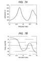
- the phase of the complex impedance shows a positive angle at a lower frequency than the resonance frequency f c , and a negative angle at a higher frequency than the resonance frequency f c .
- the phases mutually cancel each other out and a third resonance having a phase of 0° is newly generated between two resonance frequencies f c1 , f c2 .
- the resonance frequency at this time be a third resonance frequency f 3 .
- the frequency characteristic of the phase shown in FIG. 7B has the same trend as the frequency characteristic of the phase shown in FIG. 6B , and also in the birdcage-type circularly-polarized RF coil 25 , a third resonance frequency f 3 is generated between the first resonance frequency f 1 and second resonance frequency f 2 .
- the third resonance frequency f 3 lies between the first resonance frequency f 1 and second resonance frequency f 2 , and the Radiofrequency voltage applied from the feeding port 5 is converted into a current to produce a magnetic field, the RF magnetic field generated by the coil at the third resonance frequency f 3 is superimposed on the first linearly-polarized magnetic field retarded by a phase ⁇ 1 , and the second linearly-polarized magnetic field advanced by a phase ⁇ 2 .
- the linearly-polarized magnetic field has the same strength, and can be considered as a combination of two circularly-polarized magnetic fields in the clockwise and counterclockwise directions with respect to the central axis 13 of the coil
- the first linearly-polarized magnetic field whereof the phase is retarded by ⁇ 1 and second linearly-polarized magnetic field whereof the phase is advanced by ⁇ 2 can be represented as shown in FIG. 8A using vectors in a plane orthogonal to the central axis 13 of the coil.
- a magnitude B cw of the circularly-polarized magnetic field vector in the clockwise direction and a magnitude B ccw of the vector of circularly-polarized magnetic field in the counterclockwise direction may be expressed by the following equations:
- FIG. 10A shows the relation between the ratio (C 2 /C 1 ) of the values of the first capacitor 1 and second capacitor 2 and the Q value Q RF of the coil.
- the ratio of the values of the first capacitor 1 and second capacitor 2 can be found at which the birdcage-type circularly-polarized RF coil 25 , in which the value of the second capacitor 2 is less than the value of the first capacitor 1 , generates a circularly-polarized magnetic field most efficiently.
- a circularly-polarized magnetic field can be generated with only one feeding port, as in the case where a circularly-polarized magnetic field is generated in a birdcage RF coil using the QD method. Therefore, since there is one less feeding port compared to the QD method, the divider and phase shifter which were required in the prior art for a transmit coil using the QD method are now not required, and the number of parts in the transmit system can be reduced to less than half. For this reason, manufacturing costs can be lowered while adjustment of the transmit system is easier.
- the second capacitor 2 was disposed at an angle of 45° in a clockwise direction with respect to the feeding port 5 , but in addition to this embodiment, as shown in FIG. 11 , if the value of the second capacitor 2 is less than the value of the first capacitor 1 and it is disposed at an angle of 225° in the clockwise direction with respect to the feeding port 5 , then as shown in FIG.
- FIG. 11B two linearly-polarized magnetic fields of different frequencies are generated in the first direction 14 parallel to a plane orthogonal to the central axis 13 of the coil joining the second capacitor 2 to the central axis of the coil, and the second direction 15 parallel to a plane orthogonal to the central axis 13 of the coil and orthogonal to the first direction 14 , and the first resonance frequency f 1 of the first linearly-polarized magnetic field generated in the first direction 14 is higher than the second resonance frequency f 2 of the second linearly-polarized magnetic field generated in the second direction 15 .
- the spatial relationship of the linearly-polarized magnetic field shown in FIG. 11B is the same as that of FIG. 8A , and a circularly-polarized magnetic field can be generated as in this embodiment.
- the region between the loop conductor 28 and the linear conductor 30 including the 45° position i.e., in a position 22.5° to 67.5° in the clockwise direction with respect to the central axis of the birdcage-type circularly-polarized RF coil 25 from the feeding port 5 in a cross-section viewed from a direction passing through the static magnetic field 100 , it shows a value which is 95% or more of the circularly-polarized magnetic field strength at 45°.
- the region between the loop conductor 28 and the linear conductor 30 including the 225° position i.e., in a position 202.5° to 247.5° in the clockwise direction with respect to the central axis of the birdcage-type circularly-polarized RF coil 25 from the feeding port 5 in a cross-section viewed from a direction passing through the static magnetic field 100 , it shows a value which is 95% or more of the circularly-polarized magnetic field strength at 45°.
- the position of the second capacitor 2 in this embodiment is preferably such that it makes an angle of 22.5° to 67.5° or 202.5° to 247.5° in the clockwise direction with respect to the feeding port 5 , more preferably about 45° in the clockwise direction with respect to the feeding port 5 , and most preferably about 225° in the clockwise direction with respect to the feeding port 5 .
- “about” means the tolerance in the angle due to coil manufacturing errors.
- the spatial relationship of the feeding port 5 and second capacitor 2 can be extended to 8 or more linear conductors 30 .
- the birdcage-type circularly-polarized RF coil 25 shown in FIG. 3 is represented by a lumped element circuit formed by an inductor and capacitor, the part between the loop conductor 28 and linear conductor 30 including the second capacitor 2 can be represented by a serial circuit of the capacitor and inductor.
- it is preferably disposed so that it makes an angle of about 45° in the clockwise direction or about 225° in the clockwise direction with respect to the feeding port 5 .
- “about” means the tolerance in the angle due to coil manufacturing errors.
- FIG. 13 shows a modification of the birdcage-type circularly-polarized RF coil 25 shown in FIG. 3 .
- This RF coil differs from the embodiment of FIG. 3 in that there are 12 linear conductors 30 , 22 first capacitors 1 and 2 second capacitors 2 .
- the second capacitors are positioned at an angle of 45° or 225° in the clockwise direction with respect to the central axis of the birdcage-type circularly-polarized RF coil 25 in a cross-section viewed from a direction passing through the static magnetic field 100 , and are disposed so as to enclose the connection point 19 between the loop 28 and linear conductors 30 .
- the circularly-polarized magnetic field can be generated efficiently by disposing plural second capacitors 2 .
- FIG. 14 shows a modification of the birdcage-type circularly-polarized RF coil 25 shown in FIG. 3 .
- This RF coil differs from the embodiment of FIG. 3 in that a parallel circuit 7 in which an inductor 27 and capacitor 37 are connected in parallel, is disposed at the position of the second capacitor 2 .
- the impedance Z 7 of the parallel circuit 7 is given by the following equation.
- Z 7 j ⁇ ⁇ ⁇ L 27 1 - ⁇ 2 ⁇ L 27 ⁇ C 37 ( Equation ⁇ ⁇ 5 ) ⁇ is the angular frequency.
- the impedance Z 7 of the parallel circuit 7 is given by the following equation, and the parallel circuit 7 functions as a capacitor having a value C′ less than the value C 1 at the resonance frequency f c .
- Equation ⁇ ⁇ 6 Therefore, by adjusting the value L 27 of the inductor 27 so that C′ is the same value as the value C 2 of the second capacitor 2 shown in FIG. 3 , the coil shown in FIG. 14 generates a circularly-polarized magnetic field in the same way as the coil shown in FIG. 3 . From equation (6), compared with the case where the value C 2 of the second capacitor 2 is changed directly, by adjusting the value L 27 of the inductor 27 , the value of the capacitor can be adjusted more finely, and the degree of freedom of adjustment is enhanced.
- FIG. 15 shows a modification of the birdcage-type circularly-polarized RF coil 25 shown in FIG. 3 .
- This RF coil is different from the embodiment of FIG. 3 in that, instead of the second capacitor 2 shown in FIG. 3 , it has a third capacitor 3 whose capacity is larger than the value C 1 of the first capacitor 1 , and as shown in 15 B, the third capacitor 3 is disposed at a position 45° in the counterclockwise direction with respect to the central axis of the birdcage-type circularly-polarized RF coil 25 from the feeding port 5 in a cross-section viewed from a direction passing through the static magnetic field 100 .
- the value (C 3 ) of the third capacitor 3 of this coil is adjusted so that the value (C 1 ) of the first capacitor 1 satisfies the following equation.
- C 3 C 1 ( Q RF + 15 Q RF ) ( Equation ⁇ ⁇ 7 )
- Q RF is the Q value of the birdcage-type circularly-polarized RF coil 25 at the resonance frequency f c . Since the Q value takes a positive value, C 1 ⁇ C 3 .
- the birdcage-type circularly-polarized RF coil 25 shown in FIG. 15 functions as a transmit coil.
- the birdcage-type circularly-polarized RF coil 25 among plural capacitors disposed in the loop conductors 28 , 29 , only the value of the third capacitor 3 is larger than the value of the first capacitor 1 .
- the birdcage-type circularly-polarized RF coil 25 two linearly-polarized magnetic fields of different frequency are generated in the first direction 14 parallel to a plane orthogonal to the central axis 13 of the coil which joins the third capacitor 3 and the central axis of the coil, and the second direction 15 parallel to a plane orthogonal to the central axis of the coil orthogonal to the first direction, and the resonance frequency f 1 of the first linearly-polarized magnetic field generated in the first direction 14 , is lower than the resonance frequency f 2 of the second linearly-polarized magnetic field generated in the second direction 15 .
- a third resonance frequency f 3 is generated between the first resonance frequency f 1 and second resonance frequency f 2 in the same way as for the birdcage-type circularly-polarized RF coil 25 shown in FIG. 3 .
- the RF magnetic field generated by the coil at the third resonance frequency f 3 is a combination of a first linearly-polarized magnetic field whereof the phase is advanced by ⁇ 1 , and a second linearly-polarized magnetic field where of the phase is retarded by ⁇ 2 .
- the first linearly-polarized magnetic field and the second linearly-polarized magnetic field which are generated in the birdcage-type circularly-polarized RF coil 25 can be expressed as shown in FIG. 16 using vectors. Focusing only on the vectors, FIG. 16 and FIG. 8A have the same vector arrangement. Similarly to the case of the birdcage-type circularly-polarized RF coil 25 shown in FIG. 16
- FIG. 17A shows the relation between the ratio (C 3 /C 1 ) of the value of the first capacitor 1 and the third capacitor 3 and the Q value Q RF of the coil.
- the ratio of the values of the first capacitor 1 and third capacitor 3 can be found at which the birdcage-type circularly-polarized RF coil 25 , in which the value of the third capacitor 3 is larger than the value of the first capacitor 1 , generates a circularly-polarized magnetic field most efficiently.
- the third capacitor 3 was disposed at an angle of 45° in an anti clockwise direction with respect to the feeding port 5 , but in addition to this embodiment, as shown in FIG. 18 , if the value of the third capacitor 3 is larger than the value of the first capacitor 1 and it is disposed at an angle of 225° in the counterclockwise direction with respect to the feeding port 5 , then as shown in FIG.
- two linearly-polarized magnetic fields of different frequencies are generated in the first direction 14 parallel to a plane orthogonal to the central axis 13 of the coil joining the third capacitor 3 to the central axis of the coil, and the second direction 15 parallel to a plane orthogonal to the central axis 13 of the coil and orthogonal to the first direction 14 , and the first resonance frequency f 1 of the first linearly-polarized magnetic field generated in the first direction 14 is lower than the second resonance frequency f 2 of the second linearly-polarized magnetic field generated in the second direction 15 .
- the spatial relationship of the linearly-polarized magnetic fields shown in FIG. 18B is the same as that of FIG. 16 , and a circularly-polarized magnetic field can be generated as in this embodiment.
- the position of the third capacitor 3 can be moved along the loop conductor 28 .
- the position of the third capacitor 3 can be moved along the loop conductor 28 .
- the position of the third capacitor 3 can be moved along the loop conductor 28 .
- the position of the third capacitor 3 can be moved along the loop conductor 28 .
- the loop conductor 28 and the linear conductors 30 in the counterclockwise direction including the 45° position i.e., in a position 22.5° to 67.5° in the counterclockwise direction with respect to the central axis of the birdcage-type circularly-polarized RF coil 25 from the feeding port 5 in a cross-section viewed from a direction passing through the static magnetic field 100 , it shows a value which is 95% or more of the circularly-polarized magnetic field strength at 45°.
- the position of the third capacitor 3 in this embodiment is preferably such that it makes an angle of 22.5° to 67.5° or 202.5° to 247.5° in the counterclockwise direction with respect to the feeding port 5 , more preferably about 45° in the counterclockwise direction with respect to the feeding port 5 , and most preferably about 225° in the counterclockwise direction with respect to the feeding port 5 .
- “about” means the error in the angle due to coil manufacturing errors.
- the number of linear conductors 30 was 8 , but the spatial relationship between the feeding port 5 and third capacitor 3 can be extended to 8 or more linear conductors 30 .
- the birdcage-type circularly-polarized RF coil 25 shown in FIG. 15 is represented by a lumped element circuit formed by an inductor and capacitor, the part between the loop conductor 28 and linear conductors 30 including the third capacitor 3 can be represented by a serial circuit of the capacitor and inductor.
- it is preferably disposed so that it makes an angle of about 45° in the counterclockwise direction or about 225° in the counterclockwise direction with respect to the feeding port 5 .
- “about” means the error in the angle due to coil manufacturing errors.
- FIG. 19 shows a modification of the birdcage-type circularly-polarized RF coil 25 shown in FIG. 15 .
- This RF coil differs from that shown in FIG. 15 in that there are 12 linear conductors, 22 first capacitors 1 and two third capacitors 3 .
- the third capacitors 3 are positioned at an angle of 45° or 225° in the counterclockwise direction with respect to the central axis of the birdcage-type circularly-polarized RF coil 25 in a cross-section viewed from a direction passing through the static magnetic field 100 , and are disposed so as to enclose the connection point 19 between the loop 28 and linear conductors 30 .
- FIG. 20 shows a modification of the birdcage-type circularly-polarized RF coil 25 shown in FIG. 15 .
- This RF coil differs from the coil of FIG. 15 in that a serial circuit 9 in which an inductor 49 and capacitor 39 are connected in series, is disposed at the position of the third capacitor 3 .
- the impedance Z 9 of the serial circuit 9 is given by the following equation.
- FIG. 21 shows a modification of the birdcage-type circularly-polarized RF coil 25 shown in FIG. 3 .
- This RF coil is different from the embodiment of FIG. 3 in that in addition to the coil shown in FIG. 3 , as shown in FIG. 21B , there is a third capacitor 3 disposed at a position 450 in the counterclockwise direction with respect to the central axis of the birdcage-type circularly-polarized RF coil 25 from the feeding port 5 in a cross-section viewed from a direction passing through the static magnetic field 100 .
- the value (C 1 ) of the first capacitor 1 of this coil is adjusted so that the birdcage RF coil, in which the second capacitor 2 and third capacitor 3 shown in FIG. 21 are replaced by the first capacitor 1 , resonates at the resonance frequency f c .
- the birdcage-type circularly-polarized RF coil 25 shown in FIG. 21 functions as a transmit coil.
- the value of the second capacitor 2 is smaller than the value of the first capacitor 1
- the value of the third capacitor 3 is larger than the value of the first capacitor 1 .
- the birdcage-type circularly-polarized RF coil 25 two linearly-polarized magnetic fields of different frequency are generated in the first direction 14 parallel to a plane orthogonal to the central axis 13 of the coil joining the second capacitor 2 to the central axis of the coil, and the second direction 15 parallel to the plane orthogonal to the central axis of the coil joining the third capacitor 3 to the central axis of the coil, and the first resonance frequency f 1 of the first linearly-polarized magnetic field generated in the first direction 14 , is higher than the second resonance frequency f 2 of the second linearly-polarized magnetic field generated in the second direction 15 .
- the first linearly-polarized magnetic field and the second linearly-polarized magnetic field generated in the birdcage-type circularly-polarized RF coil 25 can be expressed as shown in FIG. 22 using vectors. Focusing only on the vectors, FIG. 22 and FIG. 8A have the same vector arrangement. Similarly to the case of the birdcage-type circularly-polarized RF coil 25 shown in FIG. 22
- the birdcage-type circularly-polarized RF coil 25 shown in FIG. 21 generates a circularly-polarized magnetic field in the clockwise direction, and the same effect as in the case of the birdcage-type circularly-polarized RF coil 25 shown in FIG. 3 is obtained. Also, in the case of this coil, the values of the second capacitor 2 and third capacitor 3 can be adjusted while the value C 1 of the first capacitor 1 is fixed, so coil adjustment is easy.
- the second capacitor 2 may be disposed at an angle of 225° in the clockwise direction with respect to the feeding port 5 , and even if the third capacitor 3 is also disposed at an angle of 225° in the counterclockwise direction with respect to the feeding port 5 , the spatial relationship of the two linearly-polarized magnetic fields is identical to the case of FIG. 22 , so the coil shown in FIG. 21 can perform identical functions.
- the second capacitor 2 As shown in FIG. 12 , provided that the second capacitor 2 lies between the connection points of the loop conductor 28 and linear conductors 30 including the 45° position, it has 95% or more of the circularly-polarized magnetic field strength in the 45° position, so the position of the second capacitor 2 may be 22.5° to 67.5° with respect to the feeding port 5 in the same way as in the coil shown in FIG. 3 . Further, since the second capacitor 2 may be disposed at an angle of 225° in the clockwise direction with respect to the feeding port 5 , it may be disposed also from 202.5° to 247.5°. Regarding the position of the third capacitor 3 , it may be disposed from 22.5° to 67.5°, or from 202.5° to 247.5°, with respect to the feeding port 5 in the same way as in the coil shown in FIG. 15 .
- a parallel circuit in which an inductor and capacitor are connected in parallel may be disposed instead of the second capacitor 2 in the same way as in the case of the coil shown in FIG. 14
- a serial circuit in which an inductor and capacitor are connected in series may be disposed instead of the third capacitor 3 as in the case of the coil shown in FIG. 20 .
- the circularly-polarized magnetic field can be generated efficiently by disposing plural second capacitors 2 and third capacitors 3 .
- capacitors are disposed only on the loop conductors 28 , 29 , but a fourth capacitor 4 may be disposed also on the linear conductors 30 .
- the values of the first capacitor 1 , second capacitor 2 and third capacitor 3 change, but the operating principle is the same. Therefore, a coil in which the fourth capacitor 4 is disposed on the linear conductors 30 of the birdcage-type circularly-polarized RF coil 25 shown in FIG. 3 or FIG. 15 , can generate a circularly-polarized magnetic field.
- FIG. 23 shows the construction of a birdcage-type circularly-polarized RF coil 25 according to a second embodiment of the invention.
- the 2 loop conductors 28 , 29 are disposed so that the center axes of the loops are parallel and substantially parallel to the z axis of the axes 12 , and plural (in FIG. 23A , 8 ) linear conductors 30 which are substantially linear and substantially parallel to the z axis of the axes 12 , are connected thereto.
- the plural linear conductors 30 are disposed at equidistant intervals.
- the direction of the z axis of the axes 12 is identical to the orientation of the static magnetic field 100 generated by the magnet 101 of the magnetic resonance imaging apparatus.
- the central axis of the loops is substantially identical to the orientation of the static magnetic field generated by the magnet of the magnetic resonance imaging apparatus.
- plural first capacitors 1 and second capacitor 2 are disposed, and the feeding port 5 is connected in parallel to one of the first capacitors 1 .
- the second capacitor 2 is disposed at a position about 45° in the clockwise direction with respect to the central axis of the birdcage-type circularly-polarized RF coil 25 from the feeding port 5 in a cross-section viewed from a direction passing through the static magnetic field 100 .
- “about” means the error in the angle due to manufacturing error.
- the inductances of the loop conductors 28 , 29 and linear conductors 30 are not shown. Also, when they are used as the transmit RF coil 107 and receive RF coil 114 , a circuit in which a PIN diode and inductor are connected in series, is connected in parallel to the capacitor of this coil to form a magnetic decoupling controlled by a magnetic decoupling signal, not shown.
- the values (C 1 , C 2 ) of the first capacitor 1 and second capacitor 2 in the coil of this embodiment are adjusted to respectively suitable values, respectively.
- the value (C 2 ) of the second capacitor 2 is adjusted so that the value (C 1 ) of the first capacitor 1 and following equation are satisfied.
- the birdcage-type circularly-polarized RF coil 25 shown in FIG. 23 functions as a transmit coil.
- the birdcage-type circularly-polarized RF coil 25 is such that among the plural capacitors disposed in the linear conductors 30 , only the value of the second capacitor is less than that of the first capacitor.
- the birdcage-type circularly-polarized RF coil 25 two linearly-polarized magnetic fields of different frequencies are generated in a first direction 14 parallel to a plane orthogonal to the central axis 13 of the coil joining the second capacitor 2 to the central axis 13 of the coil, and a second direction 15 parallel to a plane orthogonal to the central axis 13 of the coil and orthogonal to the first direction, and the first resonance frequency f 1 of a first linearly-polarized magnetic field generated in the first direction 14 is higher than the second resonance frequency f 2 of the second linearly-polarized magnetic field generated in the second direction 15 .
- a third resonance frequency f 3 is generated between the first resonance frequency f 1 and second resonance frequency f 2 in the same way as for the birdcage-type circularly-polarized RF coil 25 shown in FIG. 3 .
- the RF magnetic field generated by the coil at the third resonance frequency f 3 is a combination of a first linearly-polarized magnetic field whereof the phase is retarded by ⁇ 1 , and a second linearly-polarized magnetic field where of the phase is advanced by ⁇ 2 .
- the first linearly-polarized magnetic field and the second linearly-polarized magnetic field generated in the birdcage-type circularly-polarized RF coil 25 can be expressed as shown in FIG. 24 using vectors. Focusing only on the vectors, FIG. 24 and FIG. 8A have the same vector arrangement. Similarly to the case of the birdcage-type circularly-polarized RF coil 25 shown in FIG. 24
- FIG. 25A shows the relation between the ratio (C 2 /C 1 ) of the values of the first capacitor 1 and second capacitor 2 and the Q value Q RF of the coil.
- the ratio of the values of the first capacitor 1 and second capacitor 2 can be found at which the birdcage-type circularly-polarized RF coil 25 , in which the value of the second capacitor 2 is less than the value of the first capacitor 1 , generates a circularly-polarized magnetic field most efficiently.
- the birdcage-type circularly-polarized RF coil 25 in this embodiment generates a circularly-polarized magnetic field efficiently, and by preferably selecting the values (C 1 , C 2 ) of the first capacitor 1 and second capacitor 2 to satisfy equation (12), it generates a circularly-polarized magnetic field most efficiently.
- a circularly-polarized magnetic field can be generated with only one feeding port, as in the case where a circularly-polarized magnetic field is generated in a birdcage RF coil using the QD method. Therefore, since there is one less feeding port compared to the QD method, the divider and phase shifter which were required in the prior art for a transmit coil using the QD method are now not required, and the number of parts in the transmit system can be reduced to less than half. For this reason, manufacturing costs can be lowered while adjustment of the transmit system is easier.
- a parallel circuit in which an inductor and capacitor are connected in parallel may be disposed instead of the second capacitor 2 .
- FIG. 26 shows a modification of the birdcage-type circularly-polarized RF coil 25 shown in FIG. 23 .
- This RF coil differs from the embodiment of FIG. 23 in that there are 12 linear conductors 30 , ten first capacitors 1 and two second capacitors 2 .
- FIG. 27 shows a modification of the birdcage-type circularly-polarized RF coil 25 shown in FIG. 23 .
- This RF coil differs from the embodiment of FIG. 23 in that, instead of the second capacitor 2 shown in FIG. 23 , it has a third capacitor 3 whose capacity is larger than the value C 1 of the first capacitor 1 and as shown in FIG. 27B , the third capacitor 3 is disposed at a position about 45° in the counterclockwise direction with respect to the central axis of the birdcage-type circularly-polarized RF coil 25 from the feeding port 5 in a cross-section viewed from a direction passing through the static magnetic field 100 .
- “about” means the error in the angle due to manufacturing error.
- the value (C 3 ) of the third capacitor 3 of this coil is adjusted so that the value (C 1 ) of the first capacitor 1 satisfies the following equation.
- C 3 C 1 ( Q RF + 40 Q RF ) 1 4 ( Equation ⁇ ⁇ 14 )
- Q RF is the Q value of the birdcage-type circularly-polarized RF coil 25 at the resonance frequency f c . Since the Q value takes a positive value, C 1 ⁇ C 3 .
- the third capacitor 3 having a larger capacity than the value C 1 of the first capacitor 1 , is disposed at 45° in the counterclockwise direction with respect to the central axis of the birdcage-type circularly-polarized RF coil 25 from the feeding port 5 in a cross-section viewed from a direction passing through the static magnetic field 100 . Therefore, when a RF magnetic field is applied to this coil via the feeding port 5 , as shown in FIG.
- two linearly-polarized magnetic fields of different frequency are generated in the first direction 14 parallel to a plane orthogonal to the central axis 13 of the coil joining the second capacitor 2 to the central axis of the coil, and the second direction 15 parallel to a plane orthogonal to the central axis of the coil and orthogonal to the first direction, and the first resonance frequency f 1 of the first linearly-polarized magnetic field generated in the first direction 14 , is lower than the second resonance frequency f 2 of the second linearly-polarized magnetic field generated in the second direction 15 .
- a third resonance frequency f 3 is generated between the first resonance frequency f 1 and second resonance frequency f 2 in the same way as for the birdcage-type circularly-polarized RF coil 25 shown in FIG. 3 .
- the RF magnetic field generated by the coil at the third resonance frequency f 3 is a combination of a first linearly-polarized magnetic field whereof the phase is advanced by ⁇ 1 , and a second linearly-polarized magnetic field whereof the phase is retarded by ⁇ 2 .
- the first linearly-polarized magnetic field and the second linearly-polarized magnetic field which are generated in the birdcage-type circularly-polarized RF coil 25 can be expressed as shown in FIG. 28 using vectors. Focusing only on the vectors, FIG. 28 and FIG. 8A have the same vector arrangement. Similarly to the case of the birdcage-type circularly-polarized RF coil 25 shown in FIG. 28
- FIG. 29A shows the relation between the ratio (C 3 /C 1 ) of the values of the first capacitor 1 and third capacitor 3 and the Q value Q RF of the coil.
- the ratio of the values of the first capacitor 1 and third capacitor 3 can be found at which the birdcage-type circularly-polarized RF coil 25 , in which the value of the third capacitor 3 is larger than the value of the first capacitor 1 , generates a circularly-polarized magnetic field most efficiently.
- the birdcage-type circularly-polarized RF coil 25 shown in FIG. 27 generates a circularly-polarized magnetic field efficiently, and by preferably selecting the values (C 1 , C 3 ) of the first capacitor 1 and third capacitor 3 to satisfy equation (14), it generates a circularly-polarized magnetic field most efficiently.
- the same effect is obtained as for the birdcage-type circularly-polarized RF coil 25 shown in FIG. 23 .
- a serial circuit where in an inductor and capacitor are connected in series may be disposed instead of the third capacitor 3 .
- the third capacitor 3 by disposing the third capacitor 3 respectively on two linear conductors 30 adjacent to the 45° or 225° angle position in the counterclockwise direction with respect to the feeding port 5 , and adjusting the capacity of the third capacitor 3 , a circularly-polarized magnetic field can effectively be generated in the same way as in the case where the third capacitor 3 was disposed in the 45° or 225° angle position in the counterclockwise direction with respect to the feeding port 5 .
- capacitors are disposed only on the linear conductors 30 , but a fourth capacitor 4 may also be disposed on the loop conductors 28 , 29 .
- the values of the first capacitor 1 , second capacitor 2 and third capacitor 3 change, but the operating principle is the same. Therefore, a coil in which the fourth capacitor 4 is disposed on the loop conductors 28 , 29 of the birdcage-type circularly-polarized RF coil 25 shown in FIG. 23 or FIG. 27 , can generate a circularly-polarized magnetic field.
- FIG. 30 is a diagram showing the construction of this coil.
- plural (in FIG. 30A , 8 ) substantially linear conductors 47 which are substantially parallel to the axis of a cylinder conductor 46 , are disposed at substantially equidistant intervals in the circumferential direction at a constant distance from the inner surface of the cylinder conductor 46 , and their two ends are connected to the inside of the cylinder conductor 46 via connecting conductors.
- first capacitors 1 and a second capacitor 2 are inserted into the connecting conductors connecting the linear conductors 47 to the cylinder conductor 46 , and the feeding port 5 is disposed in one of the first capacitors 1 so that this coil resonates at the magnetic resonance frequency.
- the second capacitor 2 is disposed at a position about 45° in the clockwise direction with respect to the central axis 13 of the TEM-type circularly-polarized RF coil 31 from the feeding port 5 viewed from a direction passing through the static magnetic field 100 .
- “about” means the error in the angle due to manufacturing error.
- the direction of the z axis of the coordinate axes 12 is the same direction as the orientation of the static magnetic field 100 generated by the magnet 101 of the magnetic resonance imaging apparatus.
- the cylinder conductor 46 shown in FIG. 30A as can be seen from the spatial relation of the internal plural linear conductors 47 , is marked with the lateral surface of the cylinder conductor 46 as being transparent, but the lateral surface of the cylinder conductor 46 is actually covered by a conductor. In FIG. 30A , the inductances of the cylinder conductor 46 and linear conductors 47 themselves are not shown.
- a circuit in which a PIN diode and inductor are connected in series is connected in parallel to the capacitor of this coil, and a magnetic decoupling controlled by a magnetic decoupling signal is also added, not shown.
- the values (C 1 , C 2 ) of the first capacitor 1 and second capacitor 2 in the coil of this embodiment are adjusted to respectively suitable values.
- the value (C 2 ) of the second capacitor 2 is adjusted so that it is less than the value (C 1 ) of the first capacitor 1 , and so that the TEM-type circularly-polarized RF coil 31 shown in FIG. 30 resonates at the resonance frequency f c .
- the TEM-type circularly-polarized RF coil 31 shown in FIG. 30 functions as a transmit coil.
- An RF magnetic field in which the resonance frequency f c transmitted from the RF magnetic field generator 106 is the center frequency, is applied to the TEM-type circularly-polarized RF coil 31 via the feeding port 5 .
- the TEM-type circularly-polarized RF coil 31 among the plural capacitors disposed in the linear conductors 47 , only the value of the second capacitor 2 is less than that of the first capacitor 1 .
- the TEM-type circularly-polarized RF coil 31 two linearly-polarized magnetic fields of different frequency are generated in the first direction 14 parallel to a plane orthogonal to the central axis 13 of the coil joining the second capacitor 2 to the central axis of the coil, and the second direction 15 parallel to a plane orthogonal to the central axis of the coil and orthogonal to the first direction, and the first resonance frequency f 1 of the first linearly-polarized magnetic field generated in the first direction 14 is higher than the second resonance frequency f 2 of the second linearly-polarized magnetic field generated in the second direction 15 .
- the first linearly-polarized magnetic field and the second linearly-polarized magnetic field generated in the TEM-type circularly-polarized RF coil 31 can be expressed as shown in FIG. 31 using vectors. Focusing only on the vectors, FIG. 31 and FIG. 8A have the same vector arrangement. Similarly to the case of the birdcage-type circularly-polarized RF coil 25 shown in FIG.
- the TEM-type circularly-polarized RF coil 31 when the phase of ⁇ 1 and ⁇ 2 is 45°, there is only a circularly-polarized vector in the clockwise direction, and similarly to the case where a circularly-polarized magnetic field is generated by a birdcage RF coil using the QD method, the TEM-type circularly-polarized RF coil 31 generates a circularly-polarized magnetic field in the clockwise direction.
- the TEM-type circularly-polarized RF coil 31 of this embodiment can also function as an RF coil which can generate a circularly-polarized magnetic field with one feeding port, and the same effect is obtained as with the birdcage-type circularly-polarized RF coil 25 shown in the first embodiment. Also, compared to the birdcage RF coil, the TEM coil radiates a RF magnetic field with high efficiency even at a higher frequencies, and detects a magnetic resonance signal with high sensitivity, so even in a high magnetic field strength of 3 Tesla or higher, it can function stably as an RF coil.
- a parallel circuit in which an inductor and capacitor are connected in parallel may be disposed instead of the second capacitor 2 .
- FIG. 32 shows a modification of the TEM-type circularly-polarized RF coil 31 shown in FIG. 30 .
- This RF coil is different from the embodiment of FIG. 30 in that, instead of the second capacitor 2 shown in FIG. 30 , it has a third capacitor 3 whose capacity is larger than the value C 1 of the first capacitor 1 , and as shown in 32 B, the third capacitor 3 is disposed at a position 45° in the counterclockwise direction with respect to the central axis of the birdcage-type circularly-polarized RF coil 25 from the feeding port 5 in a cross-section viewed from a direction passing through the static magnetic field 100 .
- a third resonance frequency f 3 is generated between the first resonance frequency f 1 and second resonance frequency f 2 in the same way as for the TEM-type circularly-polarized RF coil 31 shown in FIG. 30 .
- the RF magnetic field generated by the coil at the third resonance frequency f 3 is a combination of a first linearly-polarized magnetic field whereof the phase is advanced by ⁇ 1 , and a second linearly-polarized magnetic field where of the phase is retarded by ⁇ 2 .
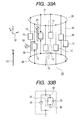
- FIG. 33 shows the construction of a double-tuned birdcage-type circularly-polarized RF coil 20 according to a fourth embodiment of the invention.
- the two loop conductors 28 , 29 shown in FIG. 33A are disposed facing each other with an axis orthogonal to the loop plane as a common axis, and plural (in FIG. 33 , 8 ) linear conductors 30 parallel to the axial direction of the loop conductors 28 , 29 are connected thereto.
- Plural first double-tuned circuits and second double-tuned circuits 11 are inserted into these plural linear conductors 30 so that this coil resonates at two magnetic resonance frequencies.
- the first double-tuned circuit 10 and second double-tuned circuit 11 include a circuit in which a parallel resonance circuit 35 including a capacitor 34 and inductor 33 is connected in series to a capacitor 36 , and a capacitor 32 , shown in FIG. 33B .
- This coil has a first feeding port 23 which supplies the signal of a first resonance frequency f c1 and a second feeding port 24 which supplies the signal of a second resonance frequency f c2 disposed in the first double-tuned circuit 10 , and as shown in FIG. 33A , the second feeding port 24 is disposed at a position 90° in the counterclockwise direction relative to the central axis of the coil from the first feeding port 23 in a cross-section viewed from a direction passing through the static magnetic field 100 . Also, the second double-tuned circuit 11 is disposed at a position 45° in the clockwise direction with respect to the central axis 13 of the coil from the first feeding port 23 in a cross-section viewed from a direction passing through the static magnetic field 100 .
- the capacitors 32 , 34 , 36 and inductor 33 forming the first double-tuned circuit 10 and second double-tuned circuit 11 in the coil of this embodiment are respectively adjusted to suitable values so that the coil resonates at two magnetic resonance frequencies.
- the first resonance frequency f c1 which is the higher frequency is a magnetic resonance frequency of 64 MHz of the proton at a magnetic field strength of 1.5 Tesla
- the second resonance frequency f c2 which is the lower frequency is a magnetic resonance frequency of 60 MHz of the fluorine atom at a magnetic field strength of 1.5 Tesla.
- the first double-tuned circuit 10 is adjusted to have a capacity of C c1 at the first resonance frequency f c1 , and to have a capacity of C c2 at the second resonance frequency f c2 .
- the second double-tuned circuit 11 is adjusted to have a capacity of C c3 at the first resonance frequency f c1 , and to have a capacity of C c4 at the second resonance frequency f c2 .
- the inductances of the loop conductors 28 , 29 and linear conductors 30 are not shown. Also when the coil is used as the transmit RF coil 107 and receive RF coil 114 , a circuit in which a PIN diode and an inductor are connected in series, is connected in parallel to the capacitor of the coil, and a magnetic decoupling controlled by a magnetic decoupling signal is added, not shown.
- the first double-tuned circuit 10 functions as a capacitor having the value C c1
- the second double-tuned circuit 11 functions as a capacitor having the value C c3 .
- C c3 which is a smaller value than C c1 is disposed at the 45° position in the clockwise direction with respect to the central axis of the coil from the first feeding port 23 , and since C c3 /C c1 satisfies equation (12), this coil has an identical construction to the birdcage-type circularly-polarized RF coil 25 shown in FIG. 23 . Therefore, this coil generates a circularly-polarized at the first resonance frequency f c1 .
- the first double-tuned circuit 10 functions as a capacitor having the value C c2
- the second double-tuned circuit 11 functions as a capacitor having the value C c4
- C c4 which is a larger value than C c2 is disposed at the 225° position in the counterclockwise direction with respect to the central axis of the coil from the second feeding port 23 , and since C c4 /C c2 satisfies equation (14), this coil has an identical construction to the birdcage-type circularly-polarized RF coil 25 shown in FIG.
- this coil generates a circularly-polarized magnetic field at the second resonance frequency f c2 . Therefore, the double-tuned birdcage-type circularly-polarized RF coil 20 shown in FIG. 33 generates a circularly-polarized magnetic field at the first and second resonance frequencies (f c1 , f c2 ).
- the second double-tuned circuit 11 was disposed at a position 45° in the clockwise direction with respect to the central axis 13 of the coil from the first feeding port 23 , but even if the second double-tuned circuit 11 is disposed a position 225° in the clockwise direction with respect to the central axis 13 of the coil from the first feeding port 23 in a cross-section viewed from a direction passing through the static magnetic field 100 , the spatial relationship of the two linearly-polarized magnetic fields generated by the double tuned birdcage-type circularly-polarized RF coil 20 does not change, so the same functions as those of the double-tuned circularly-polarized RF coil 20 shown in FIG. 33 can be performed.
- a circularly-polarized magnetic field is generated at the first and second resonance frequencies (f c1 , f c2 ) using two feeding ports for one coil. Therefore, the number of feeding ports which was four in the prior art can be reduced to half, and the number of components in the transmit system can be reduced to half or less. Hence, adjustment of the transmit system is easier, and manufacturing costs can be lowered.
- a divider or phase shifter is not used, so decrease of orthogonality due to scatter in components or mechanical distortion of the coil can be reduced, decrease in Signal-To-Noise ratio of the coil due to phase shift of a phase shifter can be suppressed, and the transmit efficiency and sensitivity of the RF coil are enhanced compared to the prior art.
- FIG. 34 shows a modification of the double-tuned birdcage-type circularly-polarized RF coil 20 shown in FIG. 33 .
- the difference from the embodiment of FIG. 33 is that the second feeding port 24 is disposed at a position 90° in the clockwise direction with respect to the central axis of the coil from the first feeding port 23 in a cross-section viewed from a direction passing through the static magnetic field 100 .
- the first double-tuned circuit 10 When the radiofrequency voltage having the first resonance frequency f c1 transmitted from the RF magnetic field generator 106 as its center frequency is applied to the double-tuned birdcage-type circularly-polarized RF coil 20 shown in FIG. 34 via the first feeding port 23 , the first double-tuned circuit 10 functions as a capacitor having the value C c1 , and the second double-tuned circuit 11 functions as a capacitor having a value C c3 .
- this coil since C c3 which is lower than C c1 is disposed at a position 45° in the clockwise direction with respect to the central axis of the coil from the first feeding port 23 , and C c3 /C c1 satisfies equation (12), this coil has the same construction as the birdcage-type circularly-polarized RF coil 25 shown in FIG. 23 . Therefore, this coil generates a circularly-polarized magnetic field at the first resonance frequency f c1 .
- the first double-tuned circuit 10 functions as a capacitor having the value C c2
- the second double-tuned circuit 11 functions as a capacitor having a value C c4 .
- this coil has the same construction as the birdcage-type circularly-polarized RF coil 25 shown in FIG. 27 . Therefore, this coil generates a circularly-polarized magnetic field at the second resonance frequency f c2 Therefore, the double tuned birdcage-type circularly-polarized RF coil 20 shown in FIG.
- the second double-tuned circuit 11 was disposed at a position 45° in the clockwise direction with respect to the central axis 13 of the coil from the first feeding port 23 , but even if the second double-tuned circuit 11 is disposed at a position 225° in the clockwise direction with respect to the central axis 13 of the coil from the first feeding port in a cross-section viewed from a direction passing through the static magnetic field 100 , the spatial relationship of the two linearly-polarized magnetic fields generated by the double-tuned birdcage-type circularly-polarized RF coil 20 does not change, so the same functions as those of the double-tuned birdcage-type circularly-polarized RF coil 20 shown in FIG. 34 can be performed.
- first double-tuned circuit 10 and second double-tuned circuit 11 were disposed in the linear conductors 30 , but likewise, even if the first double-tuned circuit 10 and second double-tuned circuit 11 are disposed in the loop conductors 28 , 29 , or the first double-tuned circuit 10 and second double-tuned circuit 11 are disposed in the plural linear conductors 47 of the TEM-type circularly-polarized RF coil shown in FIG. 30 , a circularly-polarized magnetic field can be generated at the first and second resonance frequencies (f c1 , f c2 ) as in the case of FIG. 33 .
- the RF coil of the invention is typically an RF coil in which a static magnetic field is effectively applied in the direction of the central axis of a cylindrical shape, the RF coil further including plural capacitors disposed at circumferential positions in at least one cross-section effectively orthogonal to the direction of the static magnetic field, in which the plural capacitors may include plural first capacitors, and at least one second capacitor disposed at a position from 22.5° to 67.5° or 202.5° to 247.5° in a clockwise direction with respect to the center of the cylindrical shape from the feeding port in a cross-section viewed from a direction passing through the static magnetic field, the second capacitor having a smaller capacity than the capacity of the first capacitor.
- the RF coil is typically an RF coil in which a static magnetic field is effectively applied in the direction of the central axis of a cylindrical shape, the RF coil further including plural capacitors disposed at circumferential positions in at least one cross-section which is effectively orthogonal to the direction of the static magnetic field, in which the plural capacitors may include plural first capacitors, and at least one third capacitor disposed at a position from 22.5° to 67.5° or 202.5° to 247.5° in a counterclockwise direction with respect to the center of the cylindrical shape from the feeding port in a cross-section viewed from a direction passing through the static magnetic field, the third capacitor having a larger capacity than the capacity of the first capacitor.
- the RF coil of the invention may include a parallel circuit including an inductor and capacitor instead of the second capacitor.
- the RF coil of the invention may include a serial circuit including an inductor and capacitor instead of the third capacitor.
- the RF coil of the invention may be applied specifically to a cylindrical coil such as a birdcage coil or TEM coil.
- a birdcage coil In the case of a birdcage coil, it can be applied to a low-pass birdcage coil in which plural capacitors are respectively disposed in plural linear conductors, to a high pass birdcage coil in which the plural capacitors are respectively inserted between the connection points of at least one of the aforesaid loop conductors and plural linear conductors, or to a bandwidth pass birdcage coil in which the plural capacitors are respectively inserted between the connection points of at least one of the aforesaid loop conductors and plural linear conductors, and in the plural linear conductors.
- the Q value Q RF of the coil, capacity C 1 of the first capacitor and capacity of the third capacitor C 3 may have the relation:
- C 3 C 1 ( Q RF + 40 Q RF ) 1 4 while the Q value Q RF of the coil, capacity C 1 of the first capacitor and capacity of the second capacitor C 2 , may have the relation:
- C 3 C 1 ( Q RF + 15 Q RF ) while the Q value Q RF of the coil, capacity C 1 of the first capacitor and capacity of the second capacitor C 2 , may have the relation:
- the second capacitor may be disposed at an angle of about 45° or about 225° in the clockwise direction with respect to the center of the cylindrical shape from the feeding port in the aforesaid cross-section viewed from a direction passing through the static magnetic field.
- “about” means the error in the angle due to manufacturing error.
- the third capacitor may be disposed at an angle of about 45° or about 225° in the counterclockwise direction with respect to the center of the cylindrical shape from the feeding port in the aforesaid cross-section viewed from a direction passing through the static magnetic field.
- “about” means the error in the angle due to manufacturing error.
- the RF coil has a cylindrical shape, in which a static magnetic field is applied in effectively the same direction as the direction of the central axis of the cylindrical shape, and includes plural double-tuned circuits disposed circumferentially in at least one cross-section effectively orthogonal to the direction of the static magnetic field for the purpose of resonating with a first resonance frequency and a second resonance frequency, a first feeding port which feeds a first resonance frequency signal, and a second feeding port which feeds a second resonance frequency signal, in which the second feeding port is disposed at a position 90° in the counterclockwise direction with respect to the center of the cylindrical shape from the first feeding port in the cross-section viewed from a direction passing through the static magnetic field, and the plural double-tuned circuits include plural first double-tuned circuits in which, when the first resonance frequency is higher than the second resonance frequency, the first capacity at the first resonance frequency shows a smaller value than the second capacity at the second resonance frequency, and a second double-
- the RF coil has a cylindrical shape, in which a static magnetic field is applied in effectively the same direction as the direction of the central axis of the cylindrical shape, and includes plural double-tuned circuits disposed circumferentially in at least one cross-section effectively orthogonal to the direction of the static magnetic field for the purpose of resonating with a first resonance frequency and a second resonance frequency, a first feeding port which feeds a first resonance frequency signal, and a second feeding port which feeds a second resonance frequency signal, in which the second feeding port is disposed at a position 90° in the clockwise direction with respect to the center of the cylindrical shape from the first feeding port in the cross-section viewed from a direction passing through the static magnetic field, and the plural double-tuned circuits include plural first double-tuned circuits in which, when the first resonance frequency is higher than the second resonance frequency, the first capacity at the first resonance frequency shows a smaller value than the second capacity at the second resonance frequency, and a second double-t
- a magnetic resonance imaging apparatus may use the aforesaid RF coil according to the invention comprising a static magnetic field providing instrument which forms a static magnetic field, gradient magnetic field providing instrument which forms a gradient magnetic field, RF magnetic field providing instrument which forms a RF magnetic field, a transmit coil which applies a RF magnetic field to a test subject, a receive coil which detects a magnetic resonance signal from the test subject, a receive instrument which receives a magnetic resonance signal, and a control instrument which controls the gradient magnetic field providing instrument, RF magnetic field providing instrument and receive instrument, the RF coil being used as at least one of a transmit coil and a receive coil.
- a decoupling circuit which is in the open state at the magnetic resonance frequency of the magnetic resonance signal of the test subject to be measured, may be connected to the plural capacitors.
Abstract
Description
From the above, by disposing the
ω is the angular frequency. At this time, if the value L27 of the
Therefore, by adjusting the value L27 of the
QRF is the Q value of the birdcage-type circularly-polarized
From the above, by disposing the
ω is the angular frequency. At this time, if the value L49 of the
Therefore, by adjusting the value L49 of the
C3>C1>C2 (Equation 11)
The dimensions of the birdcage-type circularly-polarized
QRF is the Q value at the resonance frequency fc of the birdcage-type circularly-polarized
QRF is the Q value of the birdcage-type circularly-polarized
while the Q value QRF of the coil, capacity C1 of the first capacitor and capacity of the second capacitor C2, may have the relation:
In the case of the aforesaid high-pass birdcage coil, the Q value QRF of the coil, capacity C1 of the first capacitor and capacity of the third capacitor C3, may have the relation:
while the Q value QRF of the coil, capacity C1 of the first capacitor and capacity of the second capacitor C2, may have the relation:
Claims (20)
Applications Claiming Priority (2)
| Application Number | Priority Date | Filing Date | Title |
|---|---|---|---|
| JP2006-247478 | 2006-09-13 | ||
| JP2006247478A JP4844310B2 (en) | 2006-09-13 | 2006-09-13 | High frequency coil and magnetic resonance imaging apparatus |
Publications (2)
| Publication Number | Publication Date |
|---|---|
| US20080061785A1 US20080061785A1 (en) | 2008-03-13 |
| US8089280B2 true US8089280B2 (en) | 2012-01-03 |
Family
ID=39168907
Family Applications (1)
| Application Number | Title | Priority Date | Filing Date |
|---|---|---|---|
| US11/782,679 Expired - Fee Related US8089280B2 (en) | 2006-09-13 | 2007-07-25 | RF coil and MRI system |
Country Status (2)
| Country | Link |
|---|---|
| US (1) | US8089280B2 (en) |
| JP (1) | JP4844310B2 (en) |
Cited By (4)
| Publication number | Priority date | Publication date | Assignee | Title |
|---|---|---|---|---|
| US20100253350A1 (en) * | 2009-04-03 | 2010-10-07 | David William Huish | Antenna assembly |
| US20140002087A1 (en) * | 2012-06-29 | 2014-01-02 | Ralph Oppelt | Method for Simultaneous Transmission of High-Frequency Transmission Signals via a Common High-Frequency Line |
| US9709645B2 (en) | 2012-11-08 | 2017-07-18 | Samsung Electronics Co., Ltd. | Phased array RF coil for magnetic resonance imaging |
| US11199596B2 (en) * | 2017-11-01 | 2021-12-14 | Hitachi, Ltd. | Array coil and magnetic resonance imaging apparatus |
Families Citing this family (19)
| Publication number | Priority date | Publication date | Assignee | Title |
|---|---|---|---|---|
| ATE477503T1 (en) * | 2005-01-24 | 2010-08-15 | Koninkl Philips Electronics Nv | ORTHOGONAL COIL FOR NUCLEAR SPIN TOMOGRAPHY |
| JP4869029B2 (en) * | 2006-11-09 | 2012-02-01 | 株式会社日立製作所 | Coil apparatus and magnetic resonance inspection apparatus using the same |
| JP4879829B2 (en) * | 2007-07-19 | 2012-02-22 | 株式会社日立製作所 | High frequency coil and magnetic resonance imaging apparatus |
| EP2540223A4 (en) * | 2010-02-26 | 2017-09-13 | Hitachi, Ltd. | Antenna device |
| JP5530848B2 (en) | 2010-07-28 | 2014-06-25 | トヨタ自動車株式会社 | Coil unit, contactless power transmission device, contactless power receiving device, vehicle, and contactless power feeding system |
| WO2012023385A1 (en) * | 2010-08-17 | 2012-02-23 | 株式会社 日立メディコ | High-frequency coil and magnetic resonance imaging device employing same |
| JP5718619B2 (en) | 2010-11-18 | 2015-05-13 | トヨタ自動車株式会社 | Coil unit, contactless power transmission device, vehicle, and contactless power supply system |
| JP5549748B2 (en) | 2011-02-15 | 2014-07-16 | トヨタ自動車株式会社 | Vehicle and external power supply device |
| JP5710313B2 (en) | 2011-02-25 | 2015-04-30 | トヨタ自動車株式会社 | Resonance coil, power transmission device, power reception device, and power transmission system |
| JP5685476B2 (en) * | 2011-04-11 | 2015-03-18 | 株式会社日立製作所 | Magnetic resonance imaging system |
| JP5781882B2 (en) * | 2011-09-29 | 2015-09-24 | トヨタ自動車株式会社 | Power transmission device, vehicle, and power transmission system |
| JP5885239B2 (en) | 2011-10-20 | 2016-03-15 | トヨタ自動車株式会社 | Power receiving device, power transmitting device, and power transmission system |
| KR101415314B1 (en) * | 2012-10-18 | 2014-07-04 | 경북대학교 산학협력단 | birdcage type dual resonant RF coil with coil sub-legs, and thereof method |
| KR101415315B1 (en) * | 2012-10-18 | 2014-07-04 | 경북대학교 산학협력단 | birdcage type RF receive coil with tripple leg capacitor, and thereof method |
| JP6391911B2 (en) | 2013-01-23 | 2018-09-19 | キヤノンメディカルシステムズ株式会社 | Magnetic resonance imaging apparatus and RF coil apparatus |
| KR102133996B1 (en) * | 2013-12-27 | 2020-07-14 | 삼성전자주식회사 | Radiofrequency Coil Structure and Radiofrequency Coil Apparatus having the same |
| US9977099B2 (en) * | 2014-12-30 | 2018-05-22 | General Electric Company | Systems and methods for integrated pick-up loops in body coil conductors |
| US11061090B2 (en) * | 2017-11-08 | 2021-07-13 | Canon Medical Systems Corporation | Magnetic resonance imaging apparatus and RF coil |
| KR102487465B1 (en) * | 2019-12-02 | 2023-01-11 | 고려대학교 세종산학협력단 | Apparatus for magnetic resonance imaging having elliptical birdcage shape for improvement of magnetic field uniformity and efficiency in whole-body rf coil |
Citations (8)
| Publication number | Priority date | Publication date | Assignee | Title |
|---|---|---|---|---|
| US4740752A (en) * | 1986-08-06 | 1988-04-26 | The Regents Of The University Of California | Non-overlapping qd MRI RF coil |
| US5041790A (en) * | 1990-01-16 | 1991-08-20 | Toshiba America Mri, Inc. | Dual-tuned RF coil for MRI spectroscopy |
| US6029082A (en) * | 1997-11-24 | 2000-02-22 | Picker International, Inc. | Less-claustrophobic, quadrature, radio-frequency head coil for nuclear magnetic resonance |
| US6414488B1 (en) * | 2000-03-01 | 2002-07-02 | Koninklijke Philips Electronics N.V. | Method and apparatus for decoupling magnetic resonance receive coils |
| US20060244453A1 (en) * | 2005-05-02 | 2006-11-02 | Doty Scientific, Inc. | Double-balanced Double-tuned CP Birdcage with Similar Field Profiles |
| US7352185B1 (en) * | 2006-11-22 | 2008-04-01 | Varian, Inc. | Multi-functional NMR probe |
| US7626390B2 (en) * | 2003-09-30 | 2009-12-01 | Koninklijke Philips Electronics N.V. | Electroacoustic cable for magnetic resonance applications |
| US7728591B2 (en) * | 2005-10-28 | 2010-06-01 | Koninklijke Philips Electronics N.V. | Imaging region-specific radio frequency coils for MRI |
Family Cites Families (4)
| Publication number | Priority date | Publication date | Assignee | Title |
|---|---|---|---|---|
| JPS63292949A (en) * | 1987-05-25 | 1988-11-30 | Yokogawa Medical Syst Ltd | Rf coil for nuclear magnetic resonance imaging apparatus |
| JP3147418B2 (en) * | 1991-08-09 | 2001-03-19 | 株式会社日立製作所 | RF coil for MRI |
| JPH06242202A (en) * | 1993-02-15 | 1994-09-02 | Hitachi Ltd | Rf probe |
| JP2638420B2 (en) * | 1993-02-28 | 1997-08-06 | 株式会社島津製作所 | Quadrature coil for MRI equipment |
-
2006
- 2006-09-13 JP JP2006247478A patent/JP4844310B2/en not_active Expired - Fee Related
-
2007
- 2007-07-25 US US11/782,679 patent/US8089280B2/en not_active Expired - Fee Related
Patent Citations (8)
| Publication number | Priority date | Publication date | Assignee | Title |
|---|---|---|---|---|
| US4740752A (en) * | 1986-08-06 | 1988-04-26 | The Regents Of The University Of California | Non-overlapping qd MRI RF coil |
| US5041790A (en) * | 1990-01-16 | 1991-08-20 | Toshiba America Mri, Inc. | Dual-tuned RF coil for MRI spectroscopy |
| US6029082A (en) * | 1997-11-24 | 2000-02-22 | Picker International, Inc. | Less-claustrophobic, quadrature, radio-frequency head coil for nuclear magnetic resonance |
| US6414488B1 (en) * | 2000-03-01 | 2002-07-02 | Koninklijke Philips Electronics N.V. | Method and apparatus for decoupling magnetic resonance receive coils |
| US7626390B2 (en) * | 2003-09-30 | 2009-12-01 | Koninklijke Philips Electronics N.V. | Electroacoustic cable for magnetic resonance applications |
| US20060244453A1 (en) * | 2005-05-02 | 2006-11-02 | Doty Scientific, Inc. | Double-balanced Double-tuned CP Birdcage with Similar Field Profiles |
| US7728591B2 (en) * | 2005-10-28 | 2010-06-01 | Koninklijke Philips Electronics N.V. | Imaging region-specific radio frequency coils for MRI |
| US7352185B1 (en) * | 2006-11-22 | 2008-04-01 | Varian, Inc. | Multi-functional NMR probe |
Non-Patent Citations (4)
| Title |
|---|
| Cecil E. Hayes, et al., "An Efficient, Highly Homogeneous RF Coil for Whole-Body NMR Imaging at 1.5 Tesla," Journal of Magnetic Resonance, vol. 63, and pp. 622-628. |
| G.H. Glover, "A Comparison of Linear and Circular Polarization for Magnetic Resonance Imaging," Journal of Magnetic Resonance, vol. 64, and pp. 255-270 (1985). |
| James Tropp et al., "The Theory of the Bird-Cage Resonator," Journal of Magnetic Resonance, vol. 82 and pp. 51-62 (1989). |
| Peter M. Joseph et al., "A Technique for Double Resonance Operation of Birdcage Imaging Coils," IEEE Transactions on Medical Imaging, 1989, 8, pp. 286-294). |
Cited By (6)
| Publication number | Priority date | Publication date | Assignee | Title |
|---|---|---|---|---|
| US20100253350A1 (en) * | 2009-04-03 | 2010-10-07 | David William Huish | Antenna assembly |
| US8427158B2 (en) * | 2009-04-03 | 2013-04-23 | Siemens Aktiengesellschaft | Antenna assembly |
| US20140002087A1 (en) * | 2012-06-29 | 2014-01-02 | Ralph Oppelt | Method for Simultaneous Transmission of High-Frequency Transmission Signals via a Common High-Frequency Line |
| US9778330B2 (en) * | 2012-06-29 | 2017-10-03 | Siemens Aktiengesellschaft | Method for simultaneous transmission of high-frequency transmission signals via a common high-frequency line |
| US9709645B2 (en) | 2012-11-08 | 2017-07-18 | Samsung Electronics Co., Ltd. | Phased array RF coil for magnetic resonance imaging |
| US11199596B2 (en) * | 2017-11-01 | 2021-12-14 | Hitachi, Ltd. | Array coil and magnetic resonance imaging apparatus |
Also Published As
| Publication number | Publication date |
|---|---|
| JP4844310B2 (en) | 2011-12-28 |
| US20080061785A1 (en) | 2008-03-13 |
| JP2008067807A (en) | 2008-03-27 |
Similar Documents
| Publication | Publication Date | Title |
|---|---|---|
| US8089280B2 (en) | RF coil and MRI system | |
| JP5675921B2 (en) | High frequency coil and magnetic resonance imaging apparatus using the same | |
| US9541614B2 (en) | High frequency coil unit and magnetic resonance imaging apparatus | |
| US8193810B2 (en) | MRI apparatus with RF surface coil having at least three resonance frequencies | |
| US7884609B2 (en) | High frequency coil and magnetic resonance imaging apparatus | |
| US9274189B2 (en) | High-frequency coil unit and magnetic resonance imaging device | |
| RU2616649C2 (en) | Multiresonance transmit/receive antenna for mr-tomogram\generation | |
| US8742759B2 (en) | High-frequency coil and magnetic resonance imaging device | |
| US7710117B2 (en) | Multi-current elements for magnetic resonance radio frequency coils | |
| JP3432896B2 (en) | High frequency equipment for nuclear spin tomography | |
| CN108627783B (en) | Radio frequency coil array and magnetic resonance imaging transmitting array | |
| US20120169340A1 (en) | Mr imaging system with freely accessible examination volume | |
| US10520564B2 (en) | High frequency coil and magnetic resonance imaging device | |
| US10641845B2 (en) | High frequency coil and magnetic resonance image pickup device | |
| WO2008075614A1 (en) | Nuclear magnetic resonance measuring device and coil unit | |
| US5280249A (en) | Circularly polarizing local antenna for a nuclear magnetic resonance apparatus | |
| US11029376B2 (en) | Radio-frequency coil for magnetic resonance device | |
| CN113504494B (en) | Four-end ring birdcage radio frequency coil system supporting three-nuclide imaging |
Legal Events
| Date | Code | Title | Description |
|---|---|---|---|
| AS | Assignment |
Owner name: HITACHI, LTD., JAPAN Free format text: ASSIGNMENT OF ASSIGNORS INTEREST;ASSIGNORS:SOUTOME, YOSHIHISA;HABARA, HIDETA;OCHI, HISAAKI;REEL/FRAME:019721/0576;SIGNING DATES FROM 20070613 TO 20070621 Owner name: HITACHI, LTD., JAPAN Free format text: ASSIGNMENT OF ASSIGNORS INTEREST;ASSIGNORS:SOUTOME, YOSHIHISA;HABARA, HIDETA;OCHI, HISAAKI;SIGNING DATES FROM 20070613 TO 20070621;REEL/FRAME:019721/0576 |
|
| FEPP | Fee payment procedure |
Free format text: PAYOR NUMBER ASSIGNED (ORIGINAL EVENT CODE: ASPN); ENTITY STATUS OF PATENT OWNER: LARGE ENTITY |
|
| STCF | Information on status: patent grant |
Free format text: PATENTED CASE |
|
| FPAY | Fee payment |
Year of fee payment: 4 |
|
| FEPP | Fee payment procedure |
Free format text: MAINTENANCE FEE REMINDER MAILED (ORIGINAL EVENT CODE: REM.); ENTITY STATUS OF PATENT OWNER: LARGE ENTITY |
|
| LAPS | Lapse for failure to pay maintenance fees |
Free format text: PATENT EXPIRED FOR FAILURE TO PAY MAINTENANCE FEES (ORIGINAL EVENT CODE: EXP.); ENTITY STATUS OF PATENT OWNER: LARGE ENTITY |
|
| STCH | Information on status: patent discontinuation |
Free format text: PATENT EXPIRED DUE TO NONPAYMENT OF MAINTENANCE FEES UNDER 37 CFR 1.362 |
|
| FP | Lapsed due to failure to pay maintenance fee |
Effective date: 20200103 |