US8090221B2 - Method and apparatus for detecting displacement with sub-pixel accuracy - Google Patents
Method and apparatus for detecting displacement with sub-pixel accuracy Download PDFInfo
- Publication number
- US8090221B2 US8090221B2 US12/020,699 US2069908A US8090221B2 US 8090221 B2 US8090221 B2 US 8090221B2 US 2069908 A US2069908 A US 2069908A US 8090221 B2 US8090221 B2 US 8090221B2
- Authority
- US
- United States
- Prior art keywords
- searching block
- searching
- image
- block
- sub
- Prior art date
- Legal status (The legal status is an assumption and is not a legal conclusion. Google has not performed a legal analysis and makes no representation as to the accuracy of the status listed.)
- Active, expires
Links
Images


Classifications
-
- G—PHYSICS
- G06—COMPUTING; CALCULATING OR COUNTING
- G06F—ELECTRIC DIGITAL DATA PROCESSING
- G06F3/00—Input arrangements for transferring data to be processed into a form capable of being handled by the computer; Output arrangements for transferring data from processing unit to output unit, e.g. interface arrangements
- G06F3/01—Input arrangements or combined input and output arrangements for interaction between user and computer
- G06F3/03—Arrangements for converting the position or the displacement of a member into a coded form
- G06F3/033—Pointing devices displaced or positioned by the user, e.g. mice, trackballs, pens or joysticks; Accessories therefor
- G06F3/0354—Pointing devices displaced or positioned by the user, e.g. mice, trackballs, pens or joysticks; Accessories therefor with detection of 2D relative movements between the device, or an operating part thereof, and a plane or surface, e.g. 2D mice, trackballs, pens or pucks
- G06F3/03543—Mice or pucks
-
- G—PHYSICS
- G06—COMPUTING; CALCULATING OR COUNTING
- G06F—ELECTRIC DIGITAL DATA PROCESSING
- G06F3/00—Input arrangements for transferring data to be processed into a form capable of being handled by the computer; Output arrangements for transferring data from processing unit to output unit, e.g. interface arrangements
- G06F3/01—Input arrangements or combined input and output arrangements for interaction between user and computer
- G06F3/03—Arrangements for converting the position or the displacement of a member into a coded form
- G06F3/0304—Detection arrangements using opto-electronic means
- G06F3/0317—Detection arrangements using opto-electronic means in co-operation with a patterned surface, e.g. absolute position or relative movement detection for an optical mouse or pen positioned with respect to a coded surface
-
- G—PHYSICS
- G06—COMPUTING; CALCULATING OR COUNTING
- G06T—IMAGE DATA PROCESSING OR GENERATION, IN GENERAL
- G06T7/00—Image analysis
- G06T7/30—Determination of transform parameters for the alignment of images, i.e. image registration
-
- G—PHYSICS
- G06—COMPUTING; CALCULATING OR COUNTING
- G06V—IMAGE OR VIDEO RECOGNITION OR UNDERSTANDING
- G06V10/00—Arrangements for image or video recognition or understanding
- G06V10/70—Arrangements for image or video recognition or understanding using pattern recognition or machine learning
- G06V10/74—Image or video pattern matching; Proximity measures in feature spaces
- G06V10/75—Organisation of the matching processes, e.g. simultaneous or sequential comparisons of image or video features; Coarse-fine approaches, e.g. multi-scale approaches; using context analysis; Selection of dictionaries
- G06V10/751—Comparing pixel values or logical combinations thereof, or feature values having positional relevance, e.g. template matching
- G06V10/7515—Shifting the patterns to accommodate for positional errors
Definitions
- This invention generally relates to a method and an apparatus for detecting image displacement, and more particularly, to a method and an apparatus for detecting displacement with sub-pixel accuracy.
- a conventional method for detecting sub-pixel displacement calculates the sub-pixel motion by the equations of approximately linear model of first order Taylor Expansion.
- the method includes the steps of: capturing a first and a second images at different time; choosing a plurality of pixels in the first image as reference pixels; calculating the partial derivatives of the reference pixels using the approximately linear model of first order Taylor Expansion from the two images and generating a plurality of first order equations; and calculating the sub-pixel motion according to the plurality of first order equations.
- Another conventional method for calculating relative displacement e.g. U.S. Pat. No. 5,729,008 entitled “Method and device for tracking relative movement by correlating signals from an array of photoelements” as shown in FIG. 1 , captures a first frame 91 of 7 ⁇ 7 pixels by an scanning device and defines a searching block 93 of 5 ⁇ 5 pixels in the central area of the first frame 91 .
- the image device captures a second frame 92 in which the searching block 93 is shifted toward different directions so as to obtain images 940 - 948 .
- a relative movement can be calculated according to a correlation between the searching block 93 in the images 940 - 948 and the second frame 92 .
- the smallest movement which can be obtained by this conventional method is a distance between two adjacent pixels of the image device, it is unable to determine a tiny movement when the tiny movement is smaller than the distance of one pixel width.
- the present invention provides a method for detecting displacement with sub-pixel accuracy including the steps of: capturing a first array image and a second array image; interpolating the first array image to form a reference image; interpolating the second array image to form a comparison image; and comparing the reference image with the comparison image so as to obtain a displacement.
- the present invention further provides a method for detecting displacement with sub-pixel accuracy including the steps of: capturing a first array image and a second array image; performing a first searching and comparison in the second array image; interpolating the first array image to form a reference image; interpolating the second array image to form a comparison image; performing a second searching and comparison in the comparison image; and calculating a displacement.
- the present invention further provides a method for detecting displacement with sub-pixel accuracy including the steps of: capturing a first array image and a second array image; interpolating the first array image to form a reference image; interpolating the second array image to form a comparison image; performing a first searching and comparison in the comparison image; performing a second searching and comparison in the comparison image; and calculating a displacement.
- the present invention further provides an apparatus for detecting displacement with sub-pixel accuracy including an image capturing unit, an interpolation unit, a storage unit and a processing unit.
- the imaging capturing unit is for capturing a first array image and a second array image of a surface.
- the interpolation unit is for interpolating the first array image and the second array image to respectively form a reference image and a comparison image.
- the storage unit is for storing the first array image, the second array image, the reference image and the comparison image.
- the processing unit is for comparing the first array image with the second array image, and/or comparing the reference image with the comparison image so as to obtain a displacement.
- the method and apparatus for detecting displacement with sub-pixel accuracy of the present invention can increase the searching region by means of interpolation and detect a tiny displacement having sub-pixel level accuracy.
- the detected results can be transmitted to an image display, e.g. a TV screen, a computer screen, a game machine screen and a projection screen, through a transmitting interface so as to correspondingly control a cursor or the aiming point of a pointer.
- Embodiments of the apparatus for detecting displacement with sub-pixel accuracy include an optical mouse and a navigation device.
- FIG. 1 shows a schematic view of a conventional method for calculating relative movements.
- FIG. 2 shows a schematic view of an apparatus for detecting displacement with sub-pixel accuracy according to one embodiment of the present invention.
- FIG. 3 shows a block diagram of an apparatus for detecting displacement with sub-pixel accuracy according to one embodiment of the present invention.
- FIG. 4 shows a schematic view of the interpolation used in the method for detecting displacement with sub-pixel accuracy according to the embodiment of the present invention.
- FIG. 5 shows a flow chart of the method for detecting displacement with sub-pixel accuracy according to the embodiment of the present invention.
- FIG. 6 shows a schematic view of the intensity distribution on a surface used in the embodiment of the present invention.
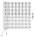
- FIG. 7 a shows a schematic view of the gray level distribution of the first array image captured by the image capturing unit according to the embodiment of the present invention.
- FIG. 7 b shows a schematic view of the gray level distribution of the second array image captured by the image capturing unit according to the embodiment of the present invention.
- FIG. 8 a shows a schematic view of the gray level distribution of one row of the first array image captured by the image capturing unit and that of the reference image according to the embodiment of the present invention, wherein the upper row shows one row of the first array image and the first reference searching block while the lower row shows one row of the reference image and the second reference searching block.
- FIG. 8 b shows a schematic view of the gray level distribution of one row of the second array image captured by the image capturing unit and that of the comparison image according to the embodiment of the present invention, wherein the upper row shows one row of the second array image and the first searching block while the lower row shows one row of the comparison image and the second searching block.
- FIG. 8 c shows another schematic view of the gray level distribution of one row of the second array image captured by the image capturing unit and that of the comparison image according to the embodiment of the present invention, wherein the first searching block moves rightward by 2 columns of intensity interval and the second searching block moves rightward by 1 column of intensity interval.
- FIG. 8 d shows another schematic view of the gray level distribution of one row of the second array image captured by the image capturing unit and that of the comparison image according to the embodiment of the present invention, wherein the first searching block further moves rightward by 2 columns of intensity interval and the second searching block further moves rightward by 1 column of intensity interval.
- FIG. 8 e shows another schematic view of the gray level distribution of one row of the second array image captured by the image capturing unit and that of the comparison image according to the embodiment of the present invention, wherein the first searching block further moves rightward by 2 columns of intensity interval and the second searching block further moves rightward by 1 column of intensity interval.
- FIG. 8 f shows another schematic view of the gray level distribution of one row of the second array image captured by the image capturing unit and that of the comparison image according to the embodiment of the present invention, wherein the first searching block has finished the searching of the second array image and the second searching block further moves rightward by 1 column of intensity interval.
- FIG. 8 g shows another schematic view of the gray level distribution of one row of the second array image captured by the image capturing unit and that of the comparison image according to the embodiment of the present invention, wherein the first searching block finished the searching of the second array image and the second searching block further moves rightward by 1 column of intensity interval.
- FIG. 8 h shows another schematic view of the gray level distribution of one row of the second array image captured by the image capturing unit and that of the comparison image according to the embodiment of the present invention, wherein the first searching block finished the searching of the second array image and the second searching block further moves rightward by 1 column of intensity interval.
- FIG. 8 i shows another schematic view of the gray level distribution of one row of the second array image captured by the image capturing unit and that of the comparison image according to the embodiment of the present invention, wherein the first searching block finished the searching of the second array image and the second searching block further moves rightward by 1 column of intensity interval.
- FIG. 8 j shows another schematic view of the gray level distribution of one row of the second array image captured by the image capturing unit and that of the comparison image according to the embodiment of the present invention, wherein the first searching block finished the searching of the second array image and the second searching block has finished the searching of the comparison image.
- FIG. 9 shows a schematic view of the comparison image and the searching points of the fourth reference point in the second searching block, wherein the second searching block has to search 81 times.
- FIG. 10 shows a flow chart of the method for fast detecting displacement with sub-pixel accuracy according to the embodiment of the present invention.
- FIG. 10 a shows a schematic view of the first searching points of the method for fast detecting displacement with sub-pixel accuracy according to the embodiment of the present invention, wherein the first searching needs 25 times.
- FIG. 10 b shows a schematic view of the second searching points of the method for fast detecting displacement with sub-pixel accuracy according to the embodiment of the present invention, wherein the second searching needs 9 times.
- FIG. 11 shows a flow chart of another method for fast detecting displacement with sub-pixel accuracy according to the embodiment of the present invention.
- FIG. 11 a shows a schematic view of the first searching points of another method for fast detecting displacement with sub-pixel accuracy according to the embodiment of the present invention, wherein the first searching needs 25 times.
- FIG. 11 b shows a schematic view of the second searching points of another method for fast detecting displacement with sub-pixel accuracy according to the embodiment of the present invention, wherein the second searching needs 9 times.
- FIGS. 2 and 3 respectively illustrate a schematic view and a block diagram of an apparatus for detecting displacement with sub-pixel accuracy 1 according to the embodiment of the present invention.
- Embodiments of the apparatus 1 include, but not limited to, an optical mouse and a navigation device.
- an optical mouse shown in FIG. 2 is served as an exemplary embodiment of the apparatus for detecting displacement with sub-pixel accuracy 1 .
- the apparatus 1 has a shell 100 having an opening “H” disposed at the bottom surface thereof and is placed on a surface “S”, e.g. the surface of a table or a mouse pad, during operation.
- a light source 101 , an image capturing unit 102 , an interpolation unit 103 , a storage unit 104 , a processing unit 105 , a transmitting unit 106 and at least one lens 107 are disposed inside the shell 100 .
- Embodiments of the light source 101 include, but not limited to, a light emitting diode (LED) and a laser diode, e.g. an infrared LED or an infrared laser diode.
- the light source 101 lights the surface “S” through the opening “H” of the shell 100 and the light reflected from the surface “S” enters the shell 100 again through the opening “H”.
- Embodiments of the image capturing unit 102 include a Charge-Coupled Device (CCD) image sensor, a Complementary Metal-Oxide-Semiconductor (CMOS) image sensor and the like.
- CCD Charge-Coupled Device
- CMOS Complementary Metal-Oxide-Semiconductor
- the image capturing unit 102 continuously captures optical images of the surface “S” through the opening “H” and converts the optical images into a plurality of array images.
- the array images are stored in the storage unit 104 at first and then the stored array images are interpolated, e.g. bilinear interpolation, by the interpolation unit 103 so as to form at least one reference image and a plurality of comparison images which will then be stored back into the storage unit 104 .
- the array images are directly interpolated by the interpolation unit 103 to form at least one reference image and a plurality of comparison images which then will be stored in the storage unit 104 .
- the processing unit 105 defines a reference searching block in the reference image, which is stored in the storage unit 104 , and defines a searching block in the comparison images, which are also stored in the storage unit 104 , and then controls the searching block to search the whole comparison image and to simultaneously compare the searching block with the reference searching block during searching process so as to calculate a displacement of the shell 100 with respect to the surface “S”.
- the detailed descriptions of the searching and interpolation processes will be illustrated in the following paragraphs.
- the calculated displacement is then transmitted to an image display (not shown), e.g.
- a lens 107 may be disposed in front of the light source 101 so as to adjust the lighting area of the light source 101 , and a lens 107 may be disposed in front of the image capturing unit 102 so as to improve the detecting efficiency of the image capturing unit 102 .
- the image capturing unit 102 captures light from the surface “S” at a first time to form a first array image 21 which is an array image of 8 ⁇ 8 pixels in this embodiment.
- the pixel at the top-left corner of the first array image 21 has a gray level value of x[m,n]; its lower adjacent pixel has a gray level value of x[m+1,n]; its right adjacent pixel has a gray level value of x[m,n+1]; its diagonal adjacent pixel has a gray level value of x[m+1,n+1] and every pixels of the first array image 21 have corresponding gray level values.
- the central area of the first array image 21 having 4 ⁇ 4 pixels is defined as a first reference searching block 211 and the pixel at the top-left corner of the first reference searching block 211 is defined as a first reference point 212 having an initial coordinate of [x start — 1 ,y start — 1 ].
- a reference image 22 can be obtained after the interpolation process, wherein the pixel at the top-left corner of the reference image 22 has a gray level value of x[2m,2n]; the second pixel below the pixel [2m,2n] has a gray level value of x[2m+p,2n]; the right second pixel of the pixel [2m,2n] has a gray level value of x[2m,2n+q]; and the diagonal second pixel of the pixel [2m,2n] has a gray level value of x[2m+p,2n+q].
- the reference image 22 contains a plurality of non-interpolated pixels having gray pixel values identical to the pixels in the first array image 21 (shown as the blank pixels in FIG. 4 , e.g. x[m,n] having a gray pixel value identical to x[2m,2n]), and a plurality of interpolated pixels which are referred to sub-pixels in the present invention (e.g. the pixels filled with oblique lines shown in FIG. 4 ).
- the first reference searching block 211 is converted to the second reference searching block 221 of 7 ⁇ 7 pixels after interpolation and the pixel at the top-left corner of the second reference searching block 221 is defined as a second reference point 222 with an initial coordinate [x start — 2 ,y start — 2 ]. It should be noted that, it is only an exemplary embodiment of the present invention to interpolate one sub-pixel between two adjacent pixels. In other embodiments, any number of sub-pixels, rather than one sub-pixel, can be interpolated into two adjacent pixels without departing from the spirit of the present invention.
- the image capturing unit 102 captures light reflected from the surface “S” at a second time to form a second array image 23 which will then be interpolated by the interpolation unit 103 to form a comparison image 24 . Since the interpolation process is identical to the process forming the reference image 22 , the detailed descriptions will not be illustrated herein.
- the comparison image 24 contains a plurality of non-interpolated pixels having gray pixel values identical to the pixels in the second array image 23 (e.g. the blank pixels shown in FIG. 4 ) and a plurality of interpolated pixels which are referred to sub-pixels in the present invention (e.g. the pixels filled with oblique lines shown in FIG. 4 ).
- the processing unit 105 defines a first searching block 231 in the second array image 23 which has the same pixel area as the first reference searching block 211 , and defines a third reference point 232 inside the first searching block 231 with a position corresponding to that of the first reference point 212 in the first reference searching block 211 .
- the processing unit 105 defines a second searching block 241 in the comparison image 24 which has the same pixel area as the second reference searching block 221 , and defines a fourth reference point 242 inside the second searching block 241 with a position corresponding to that of the second reference point 222 in the second reference searching block 221 .
- the position of the first reference point 212 inside the first reference searching block 211 is not limited to this embodiment, and each reference point can be defined at any position inside the corresponding block.
- the displacement detection based on images without interpolation of conventional method and the displacement detection method based on images with interpolation of the present invention are respectively illustrated.
- conventional method i.e. the displacement detection method based on images without interpolation
- the first searching block 231 successively searches all pixels of the second array image 23 and simultaneously compares with the first reference searching block 211 , as shown in FIG. 4 .
- the searching area of the first searching block 231 in the second array image 23 is [x start — 1 ⁇ 2, x start — 1 +2,y start — 1 ⁇ 2, y start — 1 +2], i.e.
- the searching times of the first searching block 231 in the second array image 23 and the comparison times of the first searching block 231 with the first reference searching block are 25 times.
- the comparison is to calculate a sum of the absolute values of the differences in gray level value between every pixels in the first reference searching block 211 and the pixels at corresponding positions in the first searching block 231 . Totally, 25 sums can be obtained and the smallest one of the 25 sums of the absolute values of all the differences is defined as the best matching (optimal), and the displacement will be calculated according to the optimal case.
- the second searching block 241 successively searches all pixels of the comparison image 24 and simultaneously compares with the second reference searching block 221 , as shown in FIG. 4 .
- the searching area of the second searching block 241 in the comparison image 24 is [x start — 2 ⁇ 4, x start — 2 +4,y start — 2 ⁇ 4,y start — 2 +4], i.e. the searching times of the second searching block 241 in the comparison image 24 and the comparison times of the second searching block 241 with the second reference searching block are 81 times.
- the comparison is to calculate a sum of the absolute values of the differences in gray level value between every pixels in the second reference searching block 221 and the pixels at corresponding positions in the second searching block 241 . Totally, 81 sums can be obtained and the smallest one of the 81 sums of the absolute values of all the differences is defined as the best matching (optimal), and the displacement will be calculated according to the optimal case. In this manner, the searching area can be increased after interpolation so as to improve the image resolution.
- FIG. 5 it shows a flow chart of the method for detecting displacement with sub-pixel accuracy according to one embodiment of the present invention.
- the method includes the steps of: capturing a plurality of array images (step A 1 ); storing the array images (step 2 ); interpolating (step A 3 ); storing the interpolated images (step A 4 ); searching and comparison (step A 5 ); and calculating a displacement (step A 6 ).
- the method for detecting displacement with sub-pixel accuracy will be illustrated hereinafter.
- the surface “S” is illuminated by the light source 101 and a brightness variation with 16 columns is formed thereon as shown in FIG. 6 , wherein pixels at each column have identical brightness and an interval between two adjacent columns is identical to one-half of the distance between two adjacent pixels of the sensing array (not shown) of the image capturing unit 102 .
- the sensing array shown in this embodiment has 8 ⁇ 8 pixels, the total pixel number in actual product is determined by the resolution of the sensing array.
- the capturing unit 102 captures the brightness of even columns on the surface “S” so as to form a first array image 21 , as shown in FIG. 7 a , wherein each circle represents a pixel of the sensing array and the number inside each circle denotes the brightness (gray level value) of that pixel.
- the apparatus 1 moves leftward, according to FIG. 6 , by one column distance (one-half of the distance between two adjacent pixels of the sensing array of the image capturing unit 102 ), and the image capturing unit 102 captures the brightness of odd columns on the surface “S” so as to form a second array image 23 , as shown in FIG. 7 b (step A 1 ).
- the first array image 21 and the second array image 23 can be stored into the storage unit 104 first (step A 2 ), or they can be directly interpolated by the interpolation unit 103 (step A 3 ) and then be stored in the storage unit 104 (step A 4 ).
- upper row denotes the first row 213 of the first array image 21 , wherein the rectangle with solid line represents the first reference searching block 211 of 1 ⁇ 4 pixels and the left first pixel is defined as the first reference point 212 ; lower row denotes the interpolated first row 223 of the reference image 22 (not shown), wherein the rectangle with dotted line represents the second reference searching block 221 of 1 ⁇ 7 pixels and the left first pixel is defined as the second reference point 222 .
- upper row denotes the first row 233 of the second array image 23 , wherein the rectangle with solid line represents the first searching block 231 of 1 ⁇ 4 pixels and the left first pixel is defined as the third reference point 232 , and the first searching block 231 successively searches all pixels of the first row 233 of the second array image 23 (by two columns of brightness each step); lower row denotes the first row 243 of the interpolated comparison image 24 (not shown), wherein the rectangle with dotted line represents the second searching block 241 of 1 ⁇ 7 pixels and the left first pixel is defined as the fourth reference point 242 , and the second searching block 241 successively searches all pixels of the first row 243 of the comparison image 24 (by one column of brightness each step).
- the first searching block 231 successively searches the second array image 23 and simultaneously compares with the first reference searching block 211 .
- differences in gray level value between every pixels [0,0,0,0] in the first searching block 231 and every pixels [0,0,128,128] in the first reference searching block 211 are calculated, as shown in FIG. 8 b , and a sum of the absolute values of all the differences is calculated to be 256.
- the best matching defined by the present invention is the first searching block 231 having the smallest sum of the absolute values of all the differences; therefore, 2 best matching can be obtained which have a sum of 64 as shown in FIGS. 8 d and 8 e in the conventional method without interpolation.
- the displacement is defined as a vector from the first reference point 212 to the third reference point 232 shown in FIG. 8 d , i.e. the apparatus 1 has no displacement; meanwhile, the displacement is also defined as the vector from the first reference point 212 to the third reference point 232 shown in FIG.
- the apparatus 1 may not be able to correctly estimate the moving direction and the displacement.
- the second searching block 241 successively searches the comparison image 24 and simultaneously compares with the second reference searching block 221 .
- differences in gray level value between every pixels [0,0,0,0,0,0,0] in the second searching block 241 and every pixels [0,0,0,64,128,128,128] in the second reference searching block 221 are calculated, as shown in FIG. 8 b , and a sum of the absolute values of all the differences is obtained to be 448.
- the best matching defined by the present invention is the second searching block 241 having the smallest sum of the absolute values of all the differences.
- the displacement is defined as the vector from the second reference point 222 to the fourth reference point 242 shown in FIG. 8 g (moving rightward by one column of brightness), i.e. the apparatus 1 moving leftward by one column of brightness. Accordingly, by processing interpolation, the present invention can accurately estimate the moving direction and displacement of the apparatus 1 to sub-pixel accuracy level.
- the second searching block 241 needs to search 81 times for a 15 ⁇ 15 pixels area, as shown in FIG. 9 , wherein each fourth reference point 242 has a corresponding second searching block 241 . It can be easily seen from FIG. 9 that the fourth reference point 242 needs to search 81 positions.
- the present invention further provides a method for fast detecting displacement with sub-pixel accuracy as shown in FIGS. 10 , 10 a and 10 b .
- the method includes the steps of: capturing a plurality of array images (step B 1 ); storing the array images (step B 2 ); performing the first searching and comparison (step B 3 ); interpolating (step B 4 ); storing the interpolated images (step B 5 ); performing the second searching and comparison (step B 6 ); and finally calculating a displacement (step B 7 ).
- the first searching block 231 successively searches the second array image 23 before the captured array images (step B 1 ) are interpolated so as to obtain a first optimal searching block which has a corresponding third reference point 232 (step B 3 ), e.g. pixel 234 shown in FIG. 10 a . This step needs to search and compare for 25 times.
- the second array image 23 is interpolated (step B 4 ) and the pixel 234 is converted to the pixel 244 after interpolation.
- the pixel 244 is a non-interpolated pixel and thus pixels 234 and 244 have identical gray level values or brightness values.
- the fourth reference point 242 successively searches the pixel 244 and its adjacent 8 pixels in the comparison image 24 , and the second searching block 241 corresponded to the fourth reference point 242 is compared with the second reference searching block 221 so as to obtain a second optimal searching block which has a corresponding fourth reference point 242 , e.g. pixel 245 shown in FIG. 10 b .
- FIGS. 4 , 9 , 11 , 11 a and 11 b show another method for fast detecting displacement with sub-pixel accuracy of the present invention.
- the method includes the steps of: capturing a plurality of array images (step C 1 ); interpolating (step C 2 ), storing the interpolated images (step C 3 ); performing the first searching and comparison (step C 4 ); performing the second searching and comparison (step C 5 ); and finally calculating a displacement (step C 6 ).
- the image capturing unit 102 captures the first array image 21 and the second array image 23 (step C 1 ), they are directly interpolated by the interpolation unit 103 so as to form the reference image 22 and the comparison image 24 (step C 2 ) which are then stored into the storage unit 104 (unit C 3 ).
- the processing unit 105 defines the second reference searching block 221 and the second reference point 222 in the reference image 22 , and defines the second searching block 241 and the fourth reference point 242 in the comparison image 24 ( FIG. 4 ). Then the processing unit 105 controls the second searching block 241 to successively search the comparison image 24 and compare with the second reference searching block 221 .
- the processing unit 105 controls the fourth reference point 242 to search only predetermined positions in the comparison image 24 , e.g. the positions of circles shown in FIG. 11 a (the fourth reference point 242 ), and this step needs to search 25 positions, wherein each fourth reference point 242 has a corresponding second searching block 241 . Accordingly, it is able to obtain a third optimal searching block which has a corresponding fourth reference point 242 , e.g. pixel 246 shown in FIG. 11 a , and this step needs to search and compare for 25 times (step C 4 ). This is the main difference with respect to the method for detecting displacement with sub-pixel accuracy shown in FIG. 5 , i.e. the fourth reference point 242 searches only the predetermined pixels.
- the processing unit 105 controls the fourth reference point 242 to search only the pixels 246 and its surrounding un-searched pixels, e.g. adjacent 8 pixels, and the second searching block 241 corresponded to the fourth reference point 242 is compared with the second reference searching block 221 so as to find a fourth optimal searching block which has a corresponding fourth reference point 242 , e.g. pixel 247 shown in FIG. 11 b .
- step B 7 calculate a distance between the last optimal searching point (pixel 247 ) and the second reference point 222 to be served as the displacement.
- searching and comparison times can also be significantly decreased so as to increase the calculating speed of the displacement.
- other procedures are similar to that of the method for detecting displacement with sub-pixel accuracy shown in FIG. 5 and they will not be described herein in detail.
- the method and apparatus for detecting displacement with sub-pixel accuracy of the present can increase the searching area by means of interpolation and improve the image resolution.
Abstract
Description
x[2m+p,2n+q]=(1−t)×(1−u)×x[2m,2n]+t×(1−u)×x[2m+2,2n]+(1−t)×u×x[2m,2n+2]t×u×x[2m+2,2n+2],
Claims (39)
x[2m+p,2n+q]=(1−t)×(1−u)×x[2m,2n]+t×(1−u)×x[2m+2,2n]+(1−t)×u×x[2m,2n+2]+t×u×x[2m+2,2n+2],
Priority Applications (1)
| Application Number | Priority Date | Filing Date | Title |
|---|---|---|---|
| US13/331,872 US8625934B2 (en) | 2008-01-28 | 2011-12-20 | Method and apparatus for detecting displacement with sub-pixel accuracy |
Applications Claiming Priority (3)
| Application Number | Priority Date | Filing Date | Title |
|---|---|---|---|
| TW096124918 | 2007-07-09 | ||
| TW096124918A TWI374401B (en) | 2007-07-09 | 2007-07-09 | Detection method for displacements with sub-pixel accuracy and apparatus using the same |
| TW96124918A | 2007-07-09 |
Related Child Applications (1)
| Application Number | Title | Priority Date | Filing Date |
|---|---|---|---|
| US13/331,872 Continuation-In-Part US8625934B2 (en) | 2008-01-28 | 2011-12-20 | Method and apparatus for detecting displacement with sub-pixel accuracy |
Publications (2)
| Publication Number | Publication Date |
|---|---|
| US20090016646A1 US20090016646A1 (en) | 2009-01-15 |
| US8090221B2 true US8090221B2 (en) | 2012-01-03 |
Family
ID=40253178
Family Applications (1)
| Application Number | Title | Priority Date | Filing Date |
|---|---|---|---|
| US12/020,699 Active 2030-11-04 US8090221B2 (en) | 2007-07-09 | 2008-01-28 | Method and apparatus for detecting displacement with sub-pixel accuracy |
Country Status (2)
| Country | Link |
|---|---|
| US (1) | US8090221B2 (en) |
| TW (1) | TWI374401B (en) |
Cited By (3)
| Publication number | Priority date | Publication date | Assignee | Title |
|---|---|---|---|---|
| US20110038508A1 (en) * | 2009-08-17 | 2011-02-17 | Avago Technologies Ecbu Ip (Singapore) Pte. Ltd. | System and method for performing optical navigation using portions of captured frames of image data |
| US20130202187A1 (en) * | 2012-02-07 | 2013-08-08 | Applied Materials Israel Ltd. | System, a method and a computer program product for cad-based registration |
| US9599575B2 (en) | 2012-02-07 | 2017-03-21 | Applied Materials Israel, Ltd. | System, a method and a computer program product for CAD-based registration |
Families Citing this family (6)
| Publication number | Priority date | Publication date | Assignee | Title |
|---|---|---|---|---|
| JP4958056B2 (en) * | 2009-05-12 | 2012-06-20 | 東芝ディーエムエス株式会社 | Image interpolation apparatus and image interpolation program |
| TWI390466B (en) * | 2009-09-21 | 2013-03-21 | Pixart Imaging Inc | Image denoising method |
| TWI427488B (en) * | 2010-04-23 | 2014-02-21 | Realtek Semiconductor Corp | Distance computing apparatus, lens correcting system and method applying the distance computing apparatus |
| WO2012008944A1 (en) | 2010-07-12 | 2012-01-19 | Otis Elevator Company | Speed and position detection system |
| US9310903B2 (en) * | 2013-12-09 | 2016-04-12 | Pixart Imaging Inc. | Displacement detection device with no hovering function and computer system including the same |
| CN112799525B (en) * | 2021-01-28 | 2022-08-02 | 深圳市迈特瑞光电科技有限公司 | Optical navigation auxiliary system |
Citations (5)
| Publication number | Priority date | Publication date | Assignee | Title |
|---|---|---|---|---|
| TW225622B (en) | 1992-11-12 | 1994-06-21 | Motorola Inc | |
| US5640200A (en) * | 1994-08-31 | 1997-06-17 | Cognex Corporation | Golden template comparison using efficient image registration |
| US5729008A (en) | 1996-01-25 | 1998-03-17 | Hewlett-Packard Company | Method and device for tracking relative movement by correlating signals from an array of photoelements |
| US6664948B2 (en) | 2001-07-30 | 2003-12-16 | Microsoft Corporation | Tracking pointing device motion using a single buffer for cross and auto correlation determination |
| US6996291B2 (en) * | 2001-08-06 | 2006-02-07 | Mitutoyo Corporation | Systems and methods for correlating images in an image correlation system with reduced computational loads |
-
2007
- 2007-07-09 TW TW096124918A patent/TWI374401B/en active
-
2008
- 2008-01-28 US US12/020,699 patent/US8090221B2/en active Active
Patent Citations (5)
| Publication number | Priority date | Publication date | Assignee | Title |
|---|---|---|---|---|
| TW225622B (en) | 1992-11-12 | 1994-06-21 | Motorola Inc | |
| US5640200A (en) * | 1994-08-31 | 1997-06-17 | Cognex Corporation | Golden template comparison using efficient image registration |
| US5729008A (en) | 1996-01-25 | 1998-03-17 | Hewlett-Packard Company | Method and device for tracking relative movement by correlating signals from an array of photoelements |
| US6664948B2 (en) | 2001-07-30 | 2003-12-16 | Microsoft Corporation | Tracking pointing device motion using a single buffer for cross and auto correlation determination |
| US6996291B2 (en) * | 2001-08-06 | 2006-02-07 | Mitutoyo Corporation | Systems and methods for correlating images in an image correlation system with reduced computational loads |
Cited By (6)
| Publication number | Priority date | Publication date | Assignee | Title |
|---|---|---|---|---|
| US20110038508A1 (en) * | 2009-08-17 | 2011-02-17 | Avago Technologies Ecbu Ip (Singapore) Pte. Ltd. | System and method for performing optical navigation using portions of captured frames of image data |
| US8611584B2 (en) * | 2009-08-17 | 2013-12-17 | Avago Technologies General Ip (Singapore) Pte. Ltd. | System and method for performing optical navigation using portions of captured frames of image data |
| US20130202187A1 (en) * | 2012-02-07 | 2013-08-08 | Applied Materials Israel Ltd. | System, a method and a computer program product for cad-based registration |
| US8855399B2 (en) * | 2012-02-07 | 2014-10-07 | Applied Materials Israel, Ltd. | System, a method and a computer program product for CAD-based registration |
| US9355443B2 (en) | 2012-02-07 | 2016-05-31 | Applied Materials Israel, Ltd. | System, a method and a computer program product for CAD-based registration |
| US9599575B2 (en) | 2012-02-07 | 2017-03-21 | Applied Materials Israel, Ltd. | System, a method and a computer program product for CAD-based registration |
Also Published As
| Publication number | Publication date |
|---|---|
| TW200903385A (en) | 2009-01-16 |
| TWI374401B (en) | 2012-10-11 |
| US20090016646A1 (en) | 2009-01-15 |
Similar Documents
| Publication | Publication Date | Title |
|---|---|---|
| US8090221B2 (en) | Method and apparatus for detecting displacement with sub-pixel accuracy | |
| US8625934B2 (en) | Method and apparatus for detecting displacement with sub-pixel accuracy | |
| CN107424186B (en) | Depth information measuring method and device | |
| US10663567B2 (en) | Field calibration of a structured light range-sensor | |
| US7139424B2 (en) | Stereoscopic image characteristics examination system | |
| US10142612B2 (en) | One method of binocular depth perception based on active structured light | |
| CN100442141C (en) | Image projection method and device | |
| JP4488804B2 (en) | Stereo image association method and three-dimensional data creation apparatus | |
| US8169550B2 (en) | Cursor control method and apparatus | |
| US10613228B2 (en) | Time-of-flight augmented structured light range-sensor | |
| US9115999B2 (en) | Method and system for measuring vehicle speed based on movement of video camera | |
| JP2006266848A (en) | Distance measuring device | |
| WO2018101297A1 (en) | Wire rope measuring device and wire rope measuring method | |
| JP3958638B2 (en) | Stereo image processing apparatus and stereo image processing method | |
| US11233961B2 (en) | Image processing system for measuring depth and operating method of the same | |
| US20050259737A1 (en) | Optimal correlation matching method and system for determining track behavior | |
| CN101354434B (en) | Method for detecting displacement amount of secondary pixel and apparatus for using the same | |
| JP2004069583A (en) | Image processing device | |
| US7190812B2 (en) | Method of calculating sub-pixel movement and position tracking sensor using the same | |
| CN115546072B (en) | Image distortion correction method | |
| JP4605582B2 (en) | Stereo image recognition apparatus and method | |
| JP6579727B1 (en) | Moving object detection device, moving object detection method, and moving object detection program | |
| JP3487045B2 (en) | Automatic tracking device | |
| JP2015207862A (en) | Imaging device and imaging method | |
| US10795454B2 (en) | Navigation device and calculation method of correlation search window thereof |
Legal Events
| Date | Code | Title | Description |
|---|---|---|---|
| AS | Assignment |
Owner name: PIXART IMAGING INC., TAIWAN Free format text: ASSIGNMENT OF ASSIGNORS INTEREST;ASSIGNORS:CHEN, HSIN CHIA;CHAO, TZU YI;REEL/FRAME:020422/0235 Effective date: 20080104 |
|
| STCF | Information on status: patent grant |
Free format text: PATENTED CASE |
|
| FPAY | Fee payment |
Year of fee payment: 4 |
|
| FEPP | Fee payment procedure |
Free format text: ENTITY STATUS SET TO UNDISCOUNTED (ORIGINAL EVENT CODE: BIG.); ENTITY STATUS OF PATENT OWNER: LARGE ENTITY |
|
| MAFP | Maintenance fee payment |
Free format text: PAYMENT OF MAINTENANCE FEE, 8TH YEAR, LARGE ENTITY (ORIGINAL EVENT CODE: M1552); ENTITY STATUS OF PATENT OWNER: LARGE ENTITY Year of fee payment: 8 |
|
| AS | Assignment |
Owner name: SAMSUNG ELECTRONICS CO., LTD., KOREA, REPUBLIC OF Free format text: ASSIGNMENT OF ASSIGNORS INTEREST;ASSIGNOR:PIXART IMAGING INC.;REEL/FRAME:051431/0464 Effective date: 20191216 |
|
| MAFP | Maintenance fee payment |
Free format text: PAYMENT OF MAINTENANCE FEE, 12TH YEAR, LARGE ENTITY (ORIGINAL EVENT CODE: M1553); ENTITY STATUS OF PATENT OWNER: LARGE ENTITY Year of fee payment: 12 |