US8096092B2 - Lightweight structural panel - Google Patents
Lightweight structural panel Download PDFInfo
- Publication number
- US8096092B2 US8096092B2 US11/810,549 US81054907A US8096092B2 US 8096092 B2 US8096092 B2 US 8096092B2 US 81054907 A US81054907 A US 81054907A US 8096092 B2 US8096092 B2 US 8096092B2
- Authority
- US
- United States
- Prior art keywords
- elements
- planar
- outer skin
- stiffening
- component
- Prior art date
- Legal status (The legal status is an assumption and is not a legal conclusion. Google has not performed a legal analysis and makes no representation as to the accuracy of the status listed.)
- Expired - Fee Related, expires
Links
- 230000000295 complement effect Effects 0.000 claims abstract description 16
- 229910001092 metal group alloy Inorganic materials 0.000 claims description 6
- 239000002131 composite material Substances 0.000 claims description 5
- 239000000835 fiber Substances 0.000 claims description 5
- 239000010410 layer Substances 0.000 description 52
- 230000003014 reinforcing effect Effects 0.000 description 22
- 230000007704 transition Effects 0.000 description 6
- 238000004026 adhesive bonding Methods 0.000 description 5
- 230000015572 biosynthetic process Effects 0.000 description 5
- 238000005755 formation reaction Methods 0.000 description 5
- 239000012790 adhesive layer Substances 0.000 description 4
- 238000011161 development Methods 0.000 description 4
- 230000018109 developmental process Effects 0.000 description 4
- 230000002787 reinforcement Effects 0.000 description 3
- 238000010276 construction Methods 0.000 description 2
- 238000004519 manufacturing process Methods 0.000 description 1
- 239000000463 material Substances 0.000 description 1
- 238000003466 welding Methods 0.000 description 1
Images


Classifications
-
- B—PERFORMING OPERATIONS; TRANSPORTING
- B64—AIRCRAFT; AVIATION; COSMONAUTICS
- B64C—AEROPLANES; HELICOPTERS
- B64C1/00—Fuselages; Constructional features common to fuselages, wings, stabilising surfaces or the like
- B64C1/06—Frames; Stringers; Longerons ; Fuselage sections
- B64C1/12—Construction or attachment of skin panels
-
- B—PERFORMING OPERATIONS; TRANSPORTING
- B64—AIRCRAFT; AVIATION; COSMONAUTICS
- B64C—AEROPLANES; HELICOPTERS
- B64C1/00—Fuselages; Constructional features common to fuselages, wings, stabilising surfaces or the like
- B64C1/06—Frames; Stringers; Longerons ; Fuselage sections
- B64C1/064—Stringers; Longerons
-
- E—FIXED CONSTRUCTIONS
- E04—BUILDING
- E04C—STRUCTURAL ELEMENTS; BUILDING MATERIALS
- E04C2/00—Building elements of relatively thin form for the construction of parts of buildings, e.g. sheet materials, slabs, or panels
- E04C2/02—Building elements of relatively thin form for the construction of parts of buildings, e.g. sheet materials, slabs, or panels characterised by specified materials
- E04C2/08—Building elements of relatively thin form for the construction of parts of buildings, e.g. sheet materials, slabs, or panels characterised by specified materials of metal, e.g. sheet metal
-
- E—FIXED CONSTRUCTIONS
- E04—BUILDING
- E04C—STRUCTURAL ELEMENTS; BUILDING MATERIALS
- E04C2/00—Building elements of relatively thin form for the construction of parts of buildings, e.g. sheet materials, slabs, or panels
- E04C2/02—Building elements of relatively thin form for the construction of parts of buildings, e.g. sheet materials, slabs, or panels characterised by specified materials
- E04C2/10—Building elements of relatively thin form for the construction of parts of buildings, e.g. sheet materials, slabs, or panels characterised by specified materials of wood, fibres, chips, vegetable stems, or the like; of plastics; of foamed products
- E04C2/20—Building elements of relatively thin form for the construction of parts of buildings, e.g. sheet materials, slabs, or panels characterised by specified materials of wood, fibres, chips, vegetable stems, or the like; of plastics; of foamed products of plastics
-
- E—FIXED CONSTRUCTIONS
- E04—BUILDING
- E04C—STRUCTURAL ELEMENTS; BUILDING MATERIALS
- E04C2/00—Building elements of relatively thin form for the construction of parts of buildings, e.g. sheet materials, slabs, or panels
- E04C2/02—Building elements of relatively thin form for the construction of parts of buildings, e.g. sheet materials, slabs, or panels characterised by specified materials
- E04C2/26—Building elements of relatively thin form for the construction of parts of buildings, e.g. sheet materials, slabs, or panels characterised by specified materials composed of materials covered by two or more of groups E04C2/04, E04C2/08, E04C2/10 or of materials covered by one of these groups with a material not specified in one of the groups
- E04C2/28—Building elements of relatively thin form for the construction of parts of buildings, e.g. sheet materials, slabs, or panels characterised by specified materials composed of materials covered by two or more of groups E04C2/04, E04C2/08, E04C2/10 or of materials covered by one of these groups with a material not specified in one of the groups combinations of materials fully covered by groups E04C2/04 and E04C2/08
-
- E—FIXED CONSTRUCTIONS
- E04—BUILDING
- E04C—STRUCTURAL ELEMENTS; BUILDING MATERIALS
- E04C2/00—Building elements of relatively thin form for the construction of parts of buildings, e.g. sheet materials, slabs, or panels
- E04C2/30—Building elements of relatively thin form for the construction of parts of buildings, e.g. sheet materials, slabs, or panels characterised by the shape or structure
- E04C2/38—Building elements of relatively thin form for the construction of parts of buildings, e.g. sheet materials, slabs, or panels characterised by the shape or structure with attached ribs, flanges, or the like, e.g. framed panels
-
- B—PERFORMING OPERATIONS; TRANSPORTING
- B64—AIRCRAFT; AVIATION; COSMONAUTICS
- B64C—AEROPLANES; HELICOPTERS
- B64C1/00—Fuselages; Constructional features common to fuselages, wings, stabilising surfaces or the like
- B64C2001/0054—Fuselage structures substantially made from particular materials
- B64C2001/0072—Fuselage structures substantially made from particular materials from composite materials
-
- Y—GENERAL TAGGING OF NEW TECHNOLOGICAL DEVELOPMENTS; GENERAL TAGGING OF CROSS-SECTIONAL TECHNOLOGIES SPANNING OVER SEVERAL SECTIONS OF THE IPC; TECHNICAL SUBJECTS COVERED BY FORMER USPC CROSS-REFERENCE ART COLLECTIONS [XRACs] AND DIGESTS
- Y02—TECHNOLOGIES OR APPLICATIONS FOR MITIGATION OR ADAPTATION AGAINST CLIMATE CHANGE
- Y02T—CLIMATE CHANGE MITIGATION TECHNOLOGIES RELATED TO TRANSPORTATION
- Y02T50/00—Aeronautics or air transport
- Y02T50/40—Weight reduction
-
- Y—GENERAL TAGGING OF NEW TECHNOLOGICAL DEVELOPMENTS; GENERAL TAGGING OF CROSS-SECTIONAL TECHNOLOGIES SPANNING OVER SEVERAL SECTIONS OF THE IPC; TECHNICAL SUBJECTS COVERED BY FORMER USPC CROSS-REFERENCE ART COLLECTIONS [XRACs] AND DIGESTS
- Y10—TECHNICAL SUBJECTS COVERED BY FORMER USPC
- Y10T—TECHNICAL SUBJECTS COVERED BY FORMER US CLASSIFICATION
- Y10T428/00—Stock material or miscellaneous articles
- Y10T428/24—Structurally defined web or sheet [e.g., overall dimension, etc.]
- Y10T428/24174—Structurally defined web or sheet [e.g., overall dimension, etc.] including sheet or component perpendicular to plane of web or sheet
Definitions
- the invention relates to a lightweight structural panel as is prescribed in the preamble of Claim 1 .
- a lightweight structural panel as is prescribed in the preamble of Claim 1 .
- Such a panel comprises a planarly extended outer skin of given thickness and stiffening elements connected to this outer skin and arranged at a predetermined distance from one another.
- stiffening elements in the case of lightweight structural panels, for instance on those which form the outer skin of an aircraft. These may, for example, extend in the manner of stringers in the longitudinal direction of the aircraft fuselage and have, for example, an inverted L-shaped cross section. It is conventional for such stiffening elements to be produced separately from the outer skin and then to be connected to the outer skin. At the foot of the stiffening element may be provided a leg which serves for fastening to the outer skin. The fastening can be achieved by riveting or adhesive bonding or by a combination thereof. Alternatively, the stiffening element can be welded at its foot end to the outer skin.
- DE 196 39 667 and DE 198 44 035 disclose structural components in a welded skin/stringer construction. Profiles which can take the form of stringers or frames are welded by laser beam welding to large-sized skin sheets.
- DE 199 24 909 discloses the provision of a thickened formation in the foot region of a stiffening member provided on an outer skin so as to avoid or delay crack formations. The use of additional reinforcements on stiffening profiles is also disclosed in DE 101 63 848 and DE 100 31 510.
- EP 1 439 121 A1 describes a lightweight structural component for aircraft in particular.
- the lightweight structural component is composed of at least one skin sheet and of stiffening elements arranged longitudinally or transversely, or longitudinally and transversely, thereon, these stiffening elements each being cohesively connected, either completely or at least partially, to the skin sheet by way of their foot, in which arrangement the web of the stiffening element is composed of two legs on its side facing the skin sheet and these legs are both cohesively connected to the skin sheet by means of two separate joint zones.
- the lightweight structural panel should be damage-tolerant and insensitive to crack formation as far as possible.
- the invention provides a lightweight structural panel which comprises a planarly extended outer skin of given thickness and stiffening elements which are connected to this outer skin and are arranged at a given distance from one another.
- the outer skin is formed by component layers which are each extended in the planar direction of the lightweight structural panel and complement one another in the direction of thickness to form the thickness of the outer skin and are interconnected, the stiffening elements being formed in one piece or integrally with one of the component layers.
- the outer skin is formed by a first component layer and a second component layer, and the stiffening elements are formed in one piece or integrally with the second component layer.
- the component layer with which the stiffening elements are formed in one piece or integrally is composed of a plurality of planar elements which are joined together in the planar direction.
- planar elements of the component layer with which the stiffening elements are formed in one piece or integrally may include one or more stiffening elements.
- the stiffening elements are each formed by a plurality of component elements which are formed in one piece or integrally with various planar elements and interconnected.
- the stiffening elements are each formed by two component elements, of which one is arranged on a first planar element and the other is arranged on a second planar element adjacent to the first, so that the stiffening elements are each formed by the component elements of the adjacent planar elements.
- the stiffening element comprises a region, which is formed in one piece or integrally with the component layer or its planar elements, and a further region which is formed by one or more additional reinforcing elements which are connected to the region which is formed in one piece or integrally with the component layer or its planar elements.
- the stiffening element comprises a web region arranged substantially perpendicularly to the planar direction of the outer skin and extending in a longitudinal direction along this outer skin, this web region being formed in one piece or integrally with the component layer or its planar elements.
- the stiffening element may comprise a flange region extending substantially parallel to the planar direction of the outer skin.
- the flange region is formed in one piece or integrally with the said web region.
- the stiffening element comprises one or more additional reinforcing elements which are not formed in one piece or in an integrated manner with the component layer or its planar elements.
- the stiffening element has an inverted L-shaped or J-shaped cross section, of which the vertical leg forms the web region and the other leg forms the flange region.
- the two component elements forming the stiffening element may have a same-direction inverted L- or J-shaped cross section and be tailored to one another such that they lie flat against one another and complement one another to form the stiffening element with the inverted L- or J-shaped cross section.
- the stiffening element has a T-shaped cross section, of which the vertical leg forms the web region and the horizontal leg forms the flange region.
- the two component elements forming the stiffening element may each have an opposite-direction inverted L- or J-shaped cross section and be tailored to one another such that they lie partially flat against one another and complement one another to form the T-shaped cross section of the stiffening element.
- the stiffening element has an I-shaped cross section.
- the two component elements forming the stiffening element may each have an I-shaped cross section and be tailored to one another such that they lie flat against one another and complement one another to form the I-shaped cross section of the stiffening element.
- one may have an I-shaped cross section and the other may have an inverted L-shaped cross section, the component element with the inverted L-shaped cross section being tailored to the component element with the I-shaped cross section such that it lies flat against the latter and the two component elements complement one another to form the I-shaped cross section of the stiffening element.
- the stiffening element has a box-shaped cross section which results in the formation of two web regions and a flange region connecting these web regions.
- stiffening element may have an opposite-direction L- or J-shaped cross section and be tailored to one another such that they lie flat against one another in the flange region and complement one another to form the box-shaped cross section of the stiffening element.
- the component elements may form a Y-shaped transition region situated between the web region and the component layer.
- An additional reinforcing element may be arranged between the web regions of the component elements forming the stiffening element.
- An additional reinforcing element may be arranged on that side of the flange region of the stiffening element which is opposed to the web region, this reinforcing element running along the flange region and extending at least over the width thereof.
- the additional reinforcing element may have an inverted U-shaped cross section and laterally overlap the flange region of the component elements of the stiffening element which are formed in one piece with the component layer and lie against this flange region.
- a further reinforcing element which is strip-shaped may be arranged between the reinforcing element with the inverted U-shaped cross section and the flange region of the component elements of the stiffening element which are formed in one piece with the component layer.
- the component elements may have, between the web region and the component layer, an elbowed transition region with, as a result, a recessed, substantially rectangular cross section in which is arranged a further reinforcing element which is strip-shaped.
- the stiffening element and the component layer with which the stiffening element is formed in one piece or integrally may be produced from a metal alloy.
- the stiffening element and the component layer with which the stiffening element is formed in one piece or integrally may be produced from a fibre composite material.
- the additional reinforcing elements may be produced from a metal alloy.
- the additional reinforcing elements may be produced from a fibre composite material.
- the component layers of the outer skin may be interconnected by adhesive bonding.
- the component elements of the stiffening elements and the reinforcing elements may be interconnected by adhesive bonding.
- FIG. 1 a shows a schematic, perspective, sectional view of part of an aircraft fuselage in which an application can be found for a lightweight structural panel according to exemplary embodiments of the invention
- FIG. 1 b shows a perspective, sectional, enlarged view, through such a lightweight structural panel
- FIG. 2 shows a perspective, sectional view through a lightweight structural panel according to one exemplary embodiment of the invention
- FIG. 3 shows a perspective, sectional view of a component layer of the lightweight structural panel shown in FIG. 2 , this component layer having stiffening elements formed in one piece or integrally;
- FIGS. 4 to 13 show enlarged, perspective, sectional views of details of lightweight structural panels according to various exemplary embodiments of the invention.
- FIG. 1 a is a perspective, sectional and schematic representation showing part of an aircraft fuselage in which lightweight structural panels according to exemplary embodiments of the invention can find a use for the production of the outer skin.
- FIG. 1 b is a somewhat schematic, enlarged, perspective and sectional representation showing part of such a lightweight structural panel which comprises a planarly extended outer skin 1 of given thickness and stiffening elements 11 connected to this outer skin and arranged at a given distance from one another.
- the outer skin 1 is formed by component layers 2 , 3 which are each extended in the planar direction of the lightweight structural panel 4 and which complement one another in the direction of thickness to form the thickness of the outer skin 1 .
- the component layers 2 , 3 are interconnected flat, with this connection being produced by adhesive bonding using an adhesive layer 5 in the exemplary embodiment represented.
- Stiffening elements 11 are provided on a side of the lightweight structural panel 4 that faces the inner side of the aircraft fuselage (cf. FIG. 1 a )), these stiffening elements being formed integrally or in one piece with one of the two component layers 2 , 3 of the outer skin 1 , namely the inner component layer 3 .
- the outer skin 1 is formed by a first component layer 2 and a second component layer 3
- the stiffening elements 11 are formed in one piece or integrally with the second component layer 3 .
- the component layer 3 with which the stiffening elements 11 are formed in one piece or integrally is made up of a plurality of planar elements 3 a , 3 b , 3 c which each spread from one stiffening element 11 to the next stiffening element 11 and are joined together in the planar direction, that is to say in the plane of the outer skin 1 .
- the planar elements 3 a , 3 b , 3 c of the component layer 3 with which the stiffening elements 11 are formed in one piece or integrally may each include one or more stiffening elements.
- the stiffening elements 11 are each formed by two component elements 12 , 13 , of which one is arranged on one side of a first planar element 3 a and the other is arranged on the other side of a second planar element 3 b adjacent to the first, so that the stiffening elements 11 are each constituted by the two component elements 12 , 13 of adjacent planar elements 3 a , 3 b .
- the planar elements 3 a , 3 b , 3 c are at least of substantially identical design; specifically, they each have a first component element 12 on one side and a second component element 13 on the other side, these first and second component elements 12 , 13 together each producing a stiffening element 11 .
- the component elements 12 , 13 of the stiffening elements 11 are interconnected, in the exemplary embodiment shown, by an adhesive layer 5 .
- the various exemplary embodiments represented on an enlarged scale and in detail in FIGS. 4 to 13 resemble that shown in FIG. 2 to the extent that the outer skin 1 is formed by a first component layer 2 and a second component layer 3 and the stiffening elements 11 ; 21 ; 31 ; 41 ; 51 are formed in one piece or integrally with the second component layer 3 .
- the component layer 3 with which the stiffening elements 11 ; 21 ; 31 ; 41 ; 51 are formed in one piece is likewise composed of a plurality of planar elements 3 a , 3 b which are joined together in the planar direction, that is to say in the plane of the outer skin 1 .
- the stiffening elements 11 ; 21 ; 31 ; 41 ; 51 are also each formed by two component elements 12 ; 22 ; 32 ; 42 ; 52 and 13 ; 23 ; 33 ; 43 ; 53 , of which one is arranged on one side of one planar element 3 a and the other is arranged on the other side of the other planar element 3 b adjacent to the latter, so that the stiffening elements 11 ; 21 ; 31 ; 41 ; 51 are each formed by one component element 12 ; 22 ; 32 ; 42 ; 52 of one planar element 3 a and the other component element 13 ; 23 ; 33 ; 43 ; 53 of the adjacent planar element 3 b.
- planar elements it is also possible in other exemplary embodiments for the planar elements to have more than two stiffening elements.
- the stiffening elements 11 ; 21 ; 41 ; 51 are formed solely by the respective component elements 12 , 13 and 22 , 23 and 42 , 43 and 52 , 53 which are formed in one piece or integrally with the component layer 3 .
- the stiffening elements 31 are designed such that they comprise a region which is formed in one piece with the component layer 3 or its planar elements 3 a , 3 b , consisting of the first component elements 32 and the second component elements 33 , and a further region, or further regions, which is or are formed by one or more additional reinforcing elements 36 , 37 , 38 , 39 which are connected to the region 32 , 33 which is formed in one piece with the component layer 3 or its planar elements 3 a , 3 b .
- the connection may again be in the form of adhesive layers, although these layers are not specifically represented in the figures.
- the stiffening element 11 ; 21 ; 31 ; 41 ; 51 comprises a web region 12 a , 13 a ; 22 a , 23 a ; 32 a , 33 a ; 42 a , 43 a ; 52 a , 53 a which is arranged substantially perpendicularly to the planar direction of the outer skin 1 or its component layers 2 , 3 and which extends in a longitudinal direction along the outer skin, this web region being formed by the respective component elements 12 , 13 ; 22 , 23 ; 32 , 33 ; 42 , 43 ; 52 , 53 and being formed in one piece or integrally with the component layer 3 or its planar elements 3 a , 3 b , 3 c.
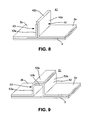
- stiffening elements 11 ; 21 ; 31 ; 41 ; 51 of the exemplary embodiments represented in FIGS. 4 , 5 , 6 and 8 to 13 are designed such that they comprise a flange region 12 b , 13 b ; 22 b , 23 b ; 32 b , 33 b ; 42 b ; 52 b , 53 b which extends substantially parallel to the planar direction of the outer skin 1 or its component layers 2 , 3 .
- This flange region is again provided on the respective component element 12 , 13 ; 22 , 23 ; 32 , 33 ; 42 ; 52 , 53 of the corresponding stiffening element 11 ; 21 ; 31 ; 41 ; 51 and formed in one piece or integrally with the corresponding web region 12 a ; 22 a ; 32 a ; 42 a ; 52 a and 13 a ; 23 a ; 33 a ; 53 a thereof.
- the stiffening element 11 ; 21 has an inverted L-shaped or J-shaped cross section, of which the vertical leg forms the web region 12 a , 13 a ; 22 a , 23 a and the other leg forms the flange region 12 b , 13 b ; 22 b , 23 b (these regions each being formed by the two component elements 12 , 13 ; 22 , 23 ).
- the two component elements 12 , 13 ; 22 , 23 forming the stiffening element 11 ; 21 have a same-direction inverted L- or J-shaped cross section and are tailored to one another such that they lie flat against one another and complement one another to form the said inverted L- or J-shaped cross section of the stiffening element 11 ; 21 .
- the stiffening element 31 generally has a T-shaped cross section, of which the vertical leg forms the web region 32 a , 33 a and the horizontal leg forms the flange region 32 b , 33 b (these regions each being formed by the two component elements 32 , 33 ), resulting from the fact that the two component elements 32 , 33 forming the stiffening element 31 have an opposite-direction inverted L- or J-shaped cross section and are tailored to one another such that they partially lie flat against one another and complement one another to form the said T-shaped cross section of the stiffening element 31 .
- the stiffening element 41 has an I-shaped cross section.
- the two component elements 42 , 43 forming the stiffening element 41 each have an I-shaped cross section and lie flat against one another such that they complement one another to form the said I-shaped cross section of the stiffening element 41 .
- FIG. 7 In the exemplary embodiment shown in FIG. 7 , the two component elements 42 , 43 forming the stiffening element 41 each have an I-shaped cross section and lie flat against one another such that they complement one another to form the said I-shaped cross section of the stiffening element 41 .
- one component element 43 has an I-shaped cross section and the other component element 42 has an inverted L-shaped cross section, the component element 42 with the inverted L-shaped cross section being tailored to the component element 43 with the I-shaped cross section such that it lies flat against the latter and such that the two component elements 42 , 43 complement one another to form the said I-shaped cross section of the stiffening element 41 .
- the stiffening element 51 has a box-shaped cross section which forms two web regions 52 a , 53 a , which are perpendicular to the layers 2 , 3 of the outer skin 1 , and a flange region 52 b , 53 b connecting them which is parallel to the layers 2 , 3 of the outer skin 1 .
- the stiffening element 51 is formed by two component elements 52 , 53 which have an opposite-direction inverted L-shaped cross section and are tailored to one another such that they lie flat against one another in the flange region 52 b , 53 b and complement one another to form the box-shaped cross section of the stiffening element 51 .
- the component elements 22 , 23 of the stiffening element 21 form, between their web regions 22 a , 23 a and the component layer 3 a , 3 b with which the component elements 22 , 23 are formed in one piece or integrally, a Y-shaped transition region 22 c , 23 c which produces an additional reinforcement of the stiffening element 21 .
- an additional reinforcing element 37 is arranged between the web regions 32 a , 33 a of the component elements 32 , 33 forming the stiffening element 31 .
- FIGS. 11 to 13 each comprise, on that side of the flange region 32 b , 33 b opposed to the component layer 3 , 3 a , 3 b , an additional reinforcement element 36 which has an inverted U-shaped cross section and laterally overlaps the flange region 32 b , 33 b of the component elements 32 , 33 formed in one piece with the component layer 3 , 3 a , 3 b and lies against this flange region.
- a further reinforcing element 38 which is strip-shaped in form is arranged between this reinforcing element 36 with the inverted U-shaped cross section and the flange region 32 b , 33 b of the component elements 32 , 33 .
- the stiffening element 31 of the exemplary embodiment represented in FIG. 13 has component elements 32 , 33 which, between their web region 32 a , 33 a and the component layer 3 a , 3 b with which they are formed in one piece or integrally, form an elbowed transition region 32 d , 33 d with, as a result, a recessed, substantially rectangular cross section in which a further reinforcing element 39 which is strip-shaped is arranged.
- the stiffening element 11 ; 21 ; 31 ; 41 ; 51 of all the exemplary embodiments and the component layer 3 , 3 a , 3 b , 3 c with which it is formed in one piece or integrally may be produced from a metal alloy or may be produced from a fibre composite material.
- the additional reinforcing elements 36 , 37 , 38 , 39 may be produced from the same material or from a different one; for example, a metal alloy for the additional reinforcing elements 36 , 37 , 38 , 39 may be combined with a fibre composite material for the parts of the stiffening element 11 ; 21 ; 31 ; 41 ; 51 which are formed in one piece or integrally with the component layer 3 , 3 a , 3 b , 3 c , or vice versa.
- the component layers 2 , 3 of the outer skin 1 can be interconnected by adhesive bonding, as can the component elements and reinforcing elements.
- the stiffening elements 11 ; 21 ; 31 ; 41 ; 51 may be formed by component elements or be formed in one piece. With a one-piece formation, the component elements 12 , 13 ; 22 , 23 ; 32 , 33 ; 42 , 43 and 52 , 53 , which are represented separately in the figures, are formed integrally as one component. In that case, the connecting surface between planar elements bearing adjacent stiffening elements is in the skin plate, or in the second component layer 3 with which the stiffening elements 11 ; 21 ; 31 ; 41 ; 51 are integrally formed.
Abstract
Description
| 1 | |
|||
| 2 | |
|||
| 3 | |
|||
| 3a, 3b, | Planar element | |||
| 4 | Lightweight |
|||
| 5 | |
|||
| 11; 21; 31; 41; 51 | |
|||
| 12; 22; 32; 42; 52 | |
|||
| 13; 23; 33; 43; 53 | |
|||
| 12a; 22a; 32a; 42a; | Web region | |||
| 13a; 23a; 33a; 43a; | Web region | |||
| 12b; 22b; 32b; 42b; | Flange region | |||
| 13b; 23b; 33b; 53b | Flange region | |||
| 32c, | Transition region | |||
| 32d, | Transition region | |||
| 36 | Reinforcing |
|||
| 37; 38; 39 | Reinforcing element | |||
| 71; 81 | Stiffening element | |||
Claims (9)
Priority Applications (2)
| Application Number | Priority Date | Filing Date | Title |
|---|---|---|---|
| US13/345,182 US9347221B2 (en) | 2006-06-06 | 2012-01-06 | Lightweight structural panel |
| US15/136,455 US9963218B2 (en) | 2006-06-06 | 2016-04-22 | Lightweight structural panel |
Applications Claiming Priority (3)
| Application Number | Priority Date | Filing Date | Title |
|---|---|---|---|
| DE102006026167 | 2006-06-06 | ||
| DE102006026167.4-24 | 2006-06-06 | ||
| DE102006026167A DE102006026167B3 (en) | 2006-06-06 | 2006-06-06 | Lightweight structural panel |
Related Child Applications (1)
| Application Number | Title | Priority Date | Filing Date |
|---|---|---|---|
| US13/345,182 Continuation US9347221B2 (en) | 2006-06-06 | 2012-01-06 | Lightweight structural panel |
Publications (2)
| Publication Number | Publication Date |
|---|---|
| US20070277470A1 US20070277470A1 (en) | 2007-12-06 |
| US8096092B2 true US8096092B2 (en) | 2012-01-17 |
Family
ID=38664016
Family Applications (3)
| Application Number | Title | Priority Date | Filing Date |
|---|---|---|---|
| US11/810,549 Expired - Fee Related US8096092B2 (en) | 2006-06-06 | 2007-06-06 | Lightweight structural panel |
| US13/345,182 Active US9347221B2 (en) | 2006-06-06 | 2012-01-06 | Lightweight structural panel |
| US15/136,455 Active US9963218B2 (en) | 2006-06-06 | 2016-04-22 | Lightweight structural panel |
Family Applications After (2)
| Application Number | Title | Priority Date | Filing Date |
|---|---|---|---|
| US13/345,182 Active US9347221B2 (en) | 2006-06-06 | 2012-01-06 | Lightweight structural panel |
| US15/136,455 Active US9963218B2 (en) | 2006-06-06 | 2016-04-22 | Lightweight structural panel |
Country Status (2)
| Country | Link |
|---|---|
| US (3) | US8096092B2 (en) |
| DE (1) | DE102006026167B3 (en) |
Cited By (6)
| Publication number | Priority date | Publication date | Assignee | Title |
|---|---|---|---|---|
| US20100264274A1 (en) * | 2009-04-20 | 2010-10-21 | Airbus Operations Limited | Edge seal for fibre-reinforced composite structure |
| US20120102869A1 (en) * | 2006-06-06 | 2012-05-03 | Airbus Operations Gmbh | Lightweight structural panel |
| US20120255258A1 (en) * | 2011-04-05 | 2012-10-11 | Airbus Operations (Sas) | Method Of Slowing The Propagation Of Cracks In A Fail Safe Structure And Fail Safe Frame, Especially For Fuselage |
| US20120285112A1 (en) * | 2009-06-18 | 2012-11-15 | Kuo-Ying Kan | Combination plate structure |
| US20150298225A1 (en) * | 2012-10-31 | 2015-10-22 | Makino Milling Machine Co., Ltd. | T-shaped cutter, rib-machining method and airplane part |
| US20200080321A1 (en) * | 2018-09-10 | 2020-03-12 | Champion Link International Corporation | Floor panel comprising a ceramic material or a natural stone |
Families Citing this family (10)
| Publication number | Priority date | Publication date | Assignee | Title |
|---|---|---|---|---|
| ES2352941B1 (en) * | 2008-05-16 | 2012-01-25 | Airbus Operations, S.L. | INTEGRATED AIRCRAFT STRUCTURE IN COMPOSITE MATERIAL |
| WO2012007780A1 (en) | 2010-07-13 | 2012-01-19 | Learjet Inc. | Composite structure and method of forming same |
| US20130125491A1 (en) * | 2011-11-23 | 2013-05-23 | Patrick M. Griffin | Wall panel structure for a refrigerated trailer |
| US9103326B2 (en) * | 2012-07-31 | 2015-08-11 | General Electric Company | Wind turbine bedplate support frame |
| US9833930B2 (en) * | 2012-10-23 | 2017-12-05 | Albany Engineered Composites, Inc. | Circumferential stiffeners for composite fancases |
| FR3030443B1 (en) * | 2014-12-18 | 2016-12-09 | Airbus Operations Sas | METHOD FOR MANUFACTURING A CENTRAL BOAT COMPONENT INTEGRATING AT LEAST ONE INTERMEDIATE LONGERON AND CENTRAL BOAT BOOM THUS OBTAINED |
| ES2777281T3 (en) * | 2015-12-18 | 2020-08-04 | Airbus Operations Sl | Pressure bulkhead |
| FR3046595B1 (en) * | 2016-01-08 | 2021-05-14 | H2X | STRAIGHTENING PROCESS FOR PLATES INTENDED FOR THE REALIZATION OF SHIP WALLS CONTAINING LAMINATED COMPOSITE MATERIALS, PLATE OBTAINED |
| US10364571B1 (en) | 2018-01-11 | 2019-07-30 | Morteza Moghaddam | Lightweight structural panel |
| DE102018112850A1 (en) | 2018-05-29 | 2019-12-05 | Airbus Operations Gmbh | Component with connected fiber composite sub-elements and method and apparatus for connecting the sub-elements |
Citations (27)
| Publication number | Priority date | Publication date | Assignee | Title |
|---|---|---|---|---|
| US2912724A (en) * | 1956-07-16 | 1959-11-17 | Boeing Co | Interior finish for aircraft cabins or the like |
| US4109435A (en) * | 1977-08-26 | 1978-08-29 | Rockwell International Corporation | Composite structural joint and method of fabrication thereof |
| US4223503A (en) * | 1979-02-26 | 1980-09-23 | H. H. Robertson Company | Joint for building panels |
| US4331495A (en) * | 1978-01-19 | 1982-05-25 | Rockwell International Corporation | Method of fabricating a reinforced composite structure |
| US4331723A (en) * | 1980-11-05 | 1982-05-25 | The Boeing Company | Advanced composite |
| US4749155A (en) * | 1985-09-30 | 1988-06-07 | The Boeing Company | Method of making wing box cover panel |
| US4786343A (en) * | 1985-05-10 | 1988-11-22 | The Boeing Company | Method of making delamination resistant composites |
| US4811540A (en) * | 1986-04-30 | 1989-03-14 | Messerschmitt-Boelkow-Blohm Gmbh | Fiber reinforced shell structure of synthetic material |
| US4908254A (en) * | 1987-03-10 | 1990-03-13 | Fischer Gesellschaft M.B.H. | Removable or hinged component for covering openings in the fuselage of an aircraft |
| US4966802A (en) * | 1985-05-10 | 1990-10-30 | The Boeing Company | Composites made of fiber reinforced resin elements joined by adhesive |
| US5259166A (en) * | 1991-08-29 | 1993-11-09 | The Louis Berkman Company | Roofing system for potable water |
| US5715640A (en) * | 1992-07-13 | 1998-02-10 | Haddock; Robert M. M. | Mounting device for controlling uplift of a metal roof |
| DE19639667C1 (en) | 1996-09-27 | 1998-03-12 | Daimler Benz Aerospace Airbus | Process for welding profiles on large-format aluminum structural components using laser beams |
| US5735486A (en) * | 1995-08-11 | 1998-04-07 | Deutsche Forschungsanstalt Fur Luft-Und Raumfahrt E.V. | Aircraft wing |
| US5811035A (en) * | 1995-06-06 | 1998-09-22 | The Marley Cooling Tower Company | Multiple purpose panel for cooling towers |
| US5922446A (en) * | 1997-07-16 | 1999-07-13 | Deutsches Zentrum Fur Luft- Und Raumfahrt E.V. | Structural members with large unidirectional rigidities |
| DE19844035C1 (en) | 1998-09-25 | 1999-11-25 | Daimler Chrysler Aerospace | Shell component for an aircraft, and method for its production |
| DE19924909C1 (en) | 1999-05-31 | 2000-06-21 | Daimler Chrysler Ag | Metallic shell structural part for aircraft fuselage comprises main plate and stiffening profiles which in foot area have a thickened formation with a specific profile foot thickness |
| US20020000492A1 (en) | 2000-06-28 | 2002-01-03 | Hans-Juergen Schmidt | Aircraft fuselage shell component with crack propagation resistance |
| US20020026756A1 (en) * | 2000-01-28 | 2002-03-07 | Larry Gumpert | Metal roofing light transmitting panel |
| DE10163848A1 (en) | 2001-12-22 | 2003-07-03 | Airbus Gmbh | Structural component for aircraft, has stiffening profile structure that comprises internal boundary surface formed between two portions, one being integral with skin sheet |
| US6620484B1 (en) * | 2000-06-06 | 2003-09-16 | The Boeing Company | Variable density stitched-composite structural elements for energy absorption |
| EP1439121A1 (en) | 2003-01-16 | 2004-07-21 | Fraunhofer-Gesellschaft zur Förderung der angewandten Forschung e.V. | Lightweight structure for aircraft and its method of production |
| US7074474B2 (en) * | 2000-12-22 | 2006-07-11 | Fuji Jukogyo Kabushiki Kaisha | Composite material-stiffened panel and manufacturing method thereof |
| US7138028B2 (en) * | 2001-07-26 | 2006-11-21 | The Boeing Company | Vacuum assisted resin transfer method for co-bonding composite laminate structures |
| US7530531B2 (en) * | 2004-10-04 | 2009-05-12 | The Boeing Company | Apparatus and methods for installing an aircraft window panel |
| US7546864B2 (en) * | 2000-09-07 | 2009-06-16 | Airbus Uk Limited | Stiffening means for structural components, method of manufacturing and apparatus therefor |
Family Cites Families (15)
| Publication number | Priority date | Publication date | Assignee | Title |
|---|---|---|---|---|
| US5242523A (en) * | 1992-05-14 | 1993-09-07 | The Boeing Company | Caul and method for bonding and curing intricate composite structures |
| DE69636148T2 (en) * | 1996-01-12 | 2007-03-01 | The Boeing Co., Chicago | Sandwich structures with several sheets and an integrated hardpoint |
| US6766984B1 (en) * | 1998-07-16 | 2004-07-27 | Icom Engineering Corporation | Stiffeners for aircraft structural panels |
| DE19845863B4 (en) * | 1998-10-05 | 2005-05-19 | Deutsches Zentrum für Luft- und Raumfahrt e.V. | Structural element with large unidirectional stiffness |
| DE10007995C2 (en) * | 2000-02-22 | 2002-03-07 | Airbus Gmbh | Structural component, in particular for an aircraft and method for producing a structural component |
| EP1261787A2 (en) * | 2000-02-25 | 2002-12-04 | The Boeing Company | Laminated composite radius filler |
| US6712315B2 (en) * | 2000-11-30 | 2004-03-30 | Airbus Deutschland Gmbh | Metal structural component for an aircraft, with resistance to crack propagation |
| US20040035979A1 (en) * | 2002-08-23 | 2004-02-26 | Mccoskey William Robert | Integrally stiffened axial load carrying skin panels for primary aircraft structure and closed loop manufacturing methods for making the same |
| US7197852B2 (en) * | 2002-09-20 | 2007-04-03 | The Boeing Company | Internally stiffened composite panels and methods for their manufacture |
| US7080805B2 (en) * | 2004-05-05 | 2006-07-25 | The Boeing Company | Stiffened structures and associated methods |
| US7325771B2 (en) * | 2004-09-23 | 2008-02-05 | The Boeing Company | Splice joints for composite aircraft fuselages and other structures |
| EP1666354B1 (en) * | 2004-12-01 | 2010-09-29 | Airbus Operations GmbH | Structural component, process for manufacturing a structural component and use of a structural component for an aircraft skin |
| DE102005033992B3 (en) * | 2005-07-21 | 2007-04-19 | Airbus Deutschland Gmbh | A method for joining at least two fabrics, in particular at least two metal sheets for a lightweight structure and compound and lightweight structure |
| DE102006026167B3 (en) | 2006-06-06 | 2007-12-13 | Airbus Deutschland Gmbh | Lightweight structural panel |
| US20080000577A1 (en) * | 2006-06-07 | 2008-01-03 | Airbus Deutschland Gmbh | Adhesive bonding arrangement for adhesively bonding two structural elements and method for producing an adhesive bond between two structural elements |
-
2006
- 2006-06-06 DE DE102006026167A patent/DE102006026167B3/en not_active Expired - Fee Related
-
2007
- 2007-06-06 US US11/810,549 patent/US8096092B2/en not_active Expired - Fee Related
-
2012
- 2012-01-06 US US13/345,182 patent/US9347221B2/en active Active
-
2016
- 2016-04-22 US US15/136,455 patent/US9963218B2/en active Active
Patent Citations (36)
| Publication number | Priority date | Publication date | Assignee | Title |
|---|---|---|---|---|
| US2912724A (en) * | 1956-07-16 | 1959-11-17 | Boeing Co | Interior finish for aircraft cabins or the like |
| US4109435A (en) * | 1977-08-26 | 1978-08-29 | Rockwell International Corporation | Composite structural joint and method of fabrication thereof |
| US4331495A (en) * | 1978-01-19 | 1982-05-25 | Rockwell International Corporation | Method of fabricating a reinforced composite structure |
| US4223503A (en) * | 1979-02-26 | 1980-09-23 | H. H. Robertson Company | Joint for building panels |
| US4331723A (en) * | 1980-11-05 | 1982-05-25 | The Boeing Company | Advanced composite |
| US4966802A (en) * | 1985-05-10 | 1990-10-30 | The Boeing Company | Composites made of fiber reinforced resin elements joined by adhesive |
| US4786343A (en) * | 1985-05-10 | 1988-11-22 | The Boeing Company | Method of making delamination resistant composites |
| US4749155A (en) * | 1985-09-30 | 1988-06-07 | The Boeing Company | Method of making wing box cover panel |
| US4811540A (en) * | 1986-04-30 | 1989-03-14 | Messerschmitt-Boelkow-Blohm Gmbh | Fiber reinforced shell structure of synthetic material |
| US4908254A (en) * | 1987-03-10 | 1990-03-13 | Fischer Gesellschaft M.B.H. | Removable or hinged component for covering openings in the fuselage of an aircraft |
| US5084120A (en) * | 1987-03-10 | 1992-01-28 | Fischer Advanced Composite Components Gesellschaft M.B.H. | Removable or hinged component for covering openings in the fuselage of an aircraft |
| US5259166A (en) * | 1991-08-29 | 1993-11-09 | The Louis Berkman Company | Roofing system for potable water |
| US5715640A (en) * | 1992-07-13 | 1998-02-10 | Haddock; Robert M. M. | Mounting device for controlling uplift of a metal roof |
| US5811035A (en) * | 1995-06-06 | 1998-09-22 | The Marley Cooling Tower Company | Multiple purpose panel for cooling towers |
| US5735486A (en) * | 1995-08-11 | 1998-04-07 | Deutsche Forschungsanstalt Fur Luft-Und Raumfahrt E.V. | Aircraft wing |
| DE19639667C1 (en) | 1996-09-27 | 1998-03-12 | Daimler Benz Aerospace Airbus | Process for welding profiles on large-format aluminum structural components using laser beams |
| US5841098A (en) | 1996-09-27 | 1998-11-24 | Daimler-Benz Aerospace Airbus Gmbh | Method and apparatus for laser welding sectional members onto large-format aluminum structural components |
| US5922446A (en) * | 1997-07-16 | 1999-07-13 | Deutsches Zentrum Fur Luft- Und Raumfahrt E.V. | Structural members with large unidirectional rigidities |
| DE19844035C1 (en) | 1998-09-25 | 1999-11-25 | Daimler Chrysler Aerospace | Shell component for an aircraft, and method for its production |
| US6364250B1 (en) | 1998-09-25 | 2002-04-02 | Daimlerchrysler Aerospace Airbus Gmbh | Shell component for an aircraft fuselage and method of manufacturing the same |
| US20010038057A1 (en) | 1999-05-31 | 2001-11-08 | Frank Palm | Stressed-skin component made of metal |
| DE19924909C1 (en) | 1999-05-31 | 2000-06-21 | Daimler Chrysler Ag | Metallic shell structural part for aircraft fuselage comprises main plate and stiffening profiles which in foot area have a thickened formation with a specific profile foot thickness |
| US20020026756A1 (en) * | 2000-01-28 | 2002-03-07 | Larry Gumpert | Metal roofing light transmitting panel |
| US6775951B2 (en) * | 2000-01-28 | 2004-08-17 | Larry Gumpert | Metal roofing light transmitting panel |
| US6620484B1 (en) * | 2000-06-06 | 2003-09-16 | The Boeing Company | Variable density stitched-composite structural elements for energy absorption |
| US20020000492A1 (en) | 2000-06-28 | 2002-01-03 | Hans-Juergen Schmidt | Aircraft fuselage shell component with crack propagation resistance |
| DE10031510A1 (en) | 2000-06-28 | 2002-01-17 | Airbus Gmbh | Structural component for an aircraft |
| US7546864B2 (en) * | 2000-09-07 | 2009-06-16 | Airbus Uk Limited | Stiffening means for structural components, method of manufacturing and apparatus therefor |
| US7074474B2 (en) * | 2000-12-22 | 2006-07-11 | Fuji Jukogyo Kabushiki Kaisha | Composite material-stiffened panel and manufacturing method thereof |
| US7138028B2 (en) * | 2001-07-26 | 2006-11-21 | The Boeing Company | Vacuum assisted resin transfer method for co-bonding composite laminate structures |
| DE10163848A1 (en) | 2001-12-22 | 2003-07-03 | Airbus Gmbh | Structural component for aircraft, has stiffening profile structure that comprises internal boundary surface formed between two portions, one being integral with skin sheet |
| US20050077427A1 (en) | 2003-01-16 | 2005-04-14 | Fraunhofer-Gesellschaft Zur Forderung Der Angewandten Forschung E.V. | Lightweight structural component in particular for aircraft and method for its production |
| EP1439121A1 (en) | 2003-01-16 | 2004-07-21 | Fraunhofer-Gesellschaft zur Förderung der angewandten Forschung e.V. | Lightweight structure for aircraft and its method of production |
| US20080296433A1 (en) | 2003-01-16 | 2008-12-04 | Fraunhofer-Gesellschaft Zuer Foerderung Der Angewandten Forschung E.V. | Lightweight structural component in particular for aircraft and method for its production |
| US7494092B2 (en) * | 2003-01-16 | 2009-02-24 | Fraunhofer-Gesellschaft zur Förderung der angewandten Forschung e.V. | Lightweight structural component in particular for aircraft and method for its production |
| US7530531B2 (en) * | 2004-10-04 | 2009-05-12 | The Boeing Company | Apparatus and methods for installing an aircraft window panel |
Non-Patent Citations (1)
| Title |
|---|
| German Office Action (with English translation) for DE 10 2006 026 167.4 dated Mar. 15, 2007. |
Cited By (13)
| Publication number | Priority date | Publication date | Assignee | Title |
|---|---|---|---|---|
| US9963218B2 (en) | 2006-06-06 | 2018-05-08 | Airbus Operations Gmbh | Lightweight structural panel |
| US20120102869A1 (en) * | 2006-06-06 | 2012-05-03 | Airbus Operations Gmbh | Lightweight structural panel |
| US9347221B2 (en) * | 2006-06-06 | 2016-05-24 | Airbus Operations Gmbh | Lightweight structural panel |
| US9764850B2 (en) * | 2009-04-20 | 2017-09-19 | Airbus Operations Limited | Edge seal for fibre-reinforced composite structure |
| US20100264274A1 (en) * | 2009-04-20 | 2010-10-21 | Airbus Operations Limited | Edge seal for fibre-reinforced composite structure |
| US20120285112A1 (en) * | 2009-06-18 | 2012-11-15 | Kuo-Ying Kan | Combination plate structure |
| US20120255258A1 (en) * | 2011-04-05 | 2012-10-11 | Airbus Operations (Sas) | Method Of Slowing The Propagation Of Cracks In A Fail Safe Structure And Fail Safe Frame, Especially For Fuselage |
| US8708281B2 (en) * | 2011-04-05 | 2014-04-29 | Airbus Operations (Sas) | Method of slowing the propagation of cracks in a fail safe structure and fail safe frame, especially for fuselage |
| US20150298225A1 (en) * | 2012-10-31 | 2015-10-22 | Makino Milling Machine Co., Ltd. | T-shaped cutter, rib-machining method and airplane part |
| US9776257B2 (en) * | 2012-10-31 | 2017-10-03 | Makino Milling Machines Co., Ltd. | T-shaped cutter, rib-machining method and airplane part |
| US20200080321A1 (en) * | 2018-09-10 | 2020-03-12 | Champion Link International Corporation | Floor panel comprising a ceramic material or a natural stone |
| US11149446B2 (en) * | 2018-09-10 | 2021-10-19 | Champion Link International Corporation | Floor panel comprising a ceramic material or a natural stone |
| US11639606B2 (en) | 2018-09-10 | 2023-05-02 | Champion Link International Corporation | Floor panel comprising a ceramic material or a natural stone |
Also Published As
| Publication number | Publication date |
|---|---|
| US20120102869A1 (en) | 2012-05-03 |
| US20070277470A1 (en) | 2007-12-06 |
| US9963218B2 (en) | 2018-05-08 |
| US9347221B2 (en) | 2016-05-24 |
| US20160311514A1 (en) | 2016-10-27 |
| DE102006026167B3 (en) | 2007-12-13 |
Similar Documents
| Publication | Publication Date | Title |
|---|---|---|
| US8096092B2 (en) | Lightweight structural panel | |
| JP4806496B2 (en) | STRUCTURAL MEMBER FOR AIRCRAFT, MANUFACTURING METHOD THEREOF, AND REINFORCED PROFILE FOR STRUCTURAL MEMBER | |
| US8302909B2 (en) | Splicing of omega-shaped stiffeners at a circumferential joint in an aircraft fuselage | |
| US8844871B2 (en) | Aircraft fuselage structural components and methods of making same | |
| US8371529B2 (en) | Interconnection and aircraft or spacecraft having such an interconnection | |
| RU2482995C1 (en) | Hybrid aircraft fuselage cell structure | |
| US8528865B2 (en) | Connecting arrangement for joining two stiffening elements having different cross-sectional profiles for an aircraft or spacecraft, and shell component | |
| RU2645500C1 (en) | Structure of composite material and containing it aircraft wing and fuselage of aircraft, method of manufacturing structures composite material | |
| CN102971212B (en) | For ruggedized construction and the aircraft of the opening in primary aircraft structure | |
| US8317134B2 (en) | Stiffened casing for an aircraft or spacecraft with a laminate stringer of high rigidity and corresponding laminate stringer | |
| US8101284B2 (en) | Fibre metal laminate panel | |
| US20110175399A1 (en) | Structure for side portion of vehicle body | |
| US8967539B2 (en) | Method for assembling a floor in a cockpit structure previously constructed from a section of aircraft fuselage | |
| JP2010137845A (en) | Aircraft cabin floor structure, system, and method | |
| US8550401B2 (en) | Modular floor section for aircraft | |
| US7124982B2 (en) | Device for bracing a shell in an aircraft fuselage | |
| JP2013544692A (en) | Reinforcement relief | |
| US9896180B2 (en) | Method for manufacturing a load bearing structure and such a load bearing structure | |
| US8679616B2 (en) | Skew-angle radius filler | |
| WO2012131137A2 (en) | Aircraft fuselage comprising highly resistant ring frames | |
| KR20190068447A (en) | Joining structure | |
| US11020912B2 (en) | Joint structure | |
| JP2021085316A (en) | Frame type structure | |
| CN103129732B (en) | There is the top load framework of the airframe of grating texture web | |
| JP5216057B2 (en) | Passenger conveyor |
Legal Events
| Date | Code | Title | Description |
|---|---|---|---|
| AS | Assignment |
Owner name: AIRBUS DEUTSCHLAND GMBH, GERMANY Free format text: ASSIGNMENT OF ASSIGNORS INTEREST;ASSIGNOR:VICHNIAKOV, ALEXEI;REEL/FRAME:019638/0016 Effective date: 20070709 |
|
| AS | Assignment |
Owner name: AIRBUS OPERATIONS GMBH, GERMANY Free format text: CHANGE OF NAME;ASSIGNOR:AIRBUS DEUTSCHLAND GMBH;REEL/FRAME:026360/0849 Effective date: 20090602 |
|
| ZAAA | Notice of allowance and fees due |
Free format text: ORIGINAL CODE: NOA |
|
| ZAAB | Notice of allowance mailed |
Free format text: ORIGINAL CODE: MN/=. |
|
| FEPP | Fee payment procedure |
Free format text: PAYOR NUMBER ASSIGNED (ORIGINAL EVENT CODE: ASPN); ENTITY STATUS OF PATENT OWNER: LARGE ENTITY |
|
| AS | Assignment |
Owner name: AIRBUS OPERATIONS GMBH, GERMANY Free format text: CHANGE OF NAME;ASSIGNOR:AIRBUS DEUTSCHLAND GMBH;REEL/FRAME:027352/0095 Effective date: 20080111 |
|
| STCF | Information on status: patent grant |
Free format text: PATENTED CASE |
|
| FPAY | Fee payment |
Year of fee payment: 4 |
|
| MAFP | Maintenance fee payment |
Free format text: PAYMENT OF MAINTENANCE FEE, 8TH YEAR, LARGE ENTITY (ORIGINAL EVENT CODE: M1552); ENTITY STATUS OF PATENT OWNER: LARGE ENTITY Year of fee payment: 8 |
|
| FEPP | Fee payment procedure |
Free format text: MAINTENANCE FEE REMINDER MAILED (ORIGINAL EVENT CODE: REM.); ENTITY STATUS OF PATENT OWNER: LARGE ENTITY |
|
| LAPS | Lapse for failure to pay maintenance fees |
Free format text: PATENT EXPIRED FOR FAILURE TO PAY MAINTENANCE FEES (ORIGINAL EVENT CODE: EXP.); ENTITY STATUS OF PATENT OWNER: LARGE ENTITY |
|
| STCH | Information on status: patent discontinuation |
Free format text: PATENT EXPIRED DUE TO NONPAYMENT OF MAINTENANCE FEES UNDER 37 CFR 1.362 |
|
| FP | Lapsed due to failure to pay maintenance fee |
Effective date: 20240117 |