US8103379B2 - Medication cabinetry - Google Patents
Medication cabinetry Download PDFInfo
- Publication number
- US8103379B2 US8103379B2 US12/351,679 US35167909A US8103379B2 US 8103379 B2 US8103379 B2 US 8103379B2 US 35167909 A US35167909 A US 35167909A US 8103379 B2 US8103379 B2 US 8103379B2
- Authority
- US
- United States
- Prior art keywords
- drawer
- controller
- unit
- cover
- coupled
- Prior art date
- Legal status (The legal status is an assumption and is not a legal conclusion. Google has not performed a legal analysis and makes no representation as to the accuracy of the status listed.)
- Active, expires
Links
Images


Classifications
-
- A—HUMAN NECESSITIES
- A47—FURNITURE; DOMESTIC ARTICLES OR APPLIANCES; COFFEE MILLS; SPICE MILLS; SUCTION CLEANERS IN GENERAL
- A47B—TABLES; DESKS; OFFICE FURNITURE; CABINETS; DRAWERS; GENERAL DETAILS OF FURNITURE
- A47B88/00—Drawers for tables, cabinets or like furniture; Guides for drawers
- A47B88/40—Sliding drawers; Slides or guides therefor
- A47B88/453—Actuated drawers
- A47B88/457—Actuated drawers operated by electrically-powered actuation means
-
- A—HUMAN NECESSITIES
- A47—FURNITURE; DOMESTIC ARTICLES OR APPLIANCES; COFFEE MILLS; SPICE MILLS; SUCTION CLEANERS IN GENERAL
- A47B—TABLES; DESKS; OFFICE FURNITURE; CABINETS; DRAWERS; GENERAL DETAILS OF FURNITURE
- A47B88/00—Drawers for tables, cabinets or like furniture; Guides for drawers
- A47B88/40—Sliding drawers; Slides or guides therefor
- A47B88/453—Actuated drawers
- A47B88/46—Actuated drawers operated by mechanically-stored energy, e.g. by springs
- A47B88/463—Actuated drawers operated by mechanically-stored energy, e.g. by springs self-opening
-
- A—HUMAN NECESSITIES
- A47—FURNITURE; DOMESTIC ARTICLES OR APPLIANCES; COFFEE MILLS; SPICE MILLS; SUCTION CLEANERS IN GENERAL
- A47B—TABLES; DESKS; OFFICE FURNITURE; CABINETS; DRAWERS; GENERAL DETAILS OF FURNITURE
- A47B88/00—Drawers for tables, cabinets or like furniture; Guides for drawers
- A47B88/40—Sliding drawers; Slides or guides therefor
- A47B88/453—Actuated drawers
- A47B88/46—Actuated drawers operated by mechanically-stored energy, e.g. by springs
- A47B88/467—Actuated drawers operated by mechanically-stored energy, e.g. by springs self-closing
-
- A—HUMAN NECESSITIES
- A47—FURNITURE; DOMESTIC ARTICLES OR APPLIANCES; COFFEE MILLS; SPICE MILLS; SUCTION CLEANERS IN GENERAL
- A47B—TABLES; DESKS; OFFICE FURNITURE; CABINETS; DRAWERS; GENERAL DETAILS OF FURNITURE
- A47B88/00—Drawers for tables, cabinets or like furniture; Guides for drawers
- A47B88/50—Safety devices or the like for drawers
- A47B88/57—Safety devices or the like for drawers preventing complete withdrawal of the drawer
-
- G—PHYSICS
- G06—COMPUTING; CALCULATING OR COUNTING
- G06F—ELECTRIC DIGITAL DATA PROCESSING
- G06F3/00—Input arrangements for transferring data to be processed into a form capable of being handled by the computer; Output arrangements for transferring data from processing unit to output unit, e.g. interface arrangements
- G06F3/01—Input arrangements or combined input and output arrangements for interaction between user and computer
- G06F3/048—Interaction techniques based on graphical user interfaces [GUI]
- G06F3/0484—Interaction techniques based on graphical user interfaces [GUI] for the control of specific functions or operations, e.g. selecting or manipulating an object, an image or a displayed text element, setting a parameter value or selecting a range
- G06F3/04842—Selection of displayed objects or displayed text elements
-
- G—PHYSICS
- G07—CHECKING-DEVICES
- G07F—COIN-FREED OR LIKE APPARATUS
- G07F11/00—Coin-freed apparatus for dispensing, or the like, discrete articles
- G07F11/02—Coin-freed apparatus for dispensing, or the like, discrete articles from non-movable magazines
- G07F11/04—Coin-freed apparatus for dispensing, or the like, discrete articles from non-movable magazines in which magazines the articles are stored one vertically above the other
- G07F11/16—Delivery means
- G07F11/18—Recessed drawers
-
- G—PHYSICS
- G07—CHECKING-DEVICES
- G07F—COIN-FREED OR LIKE APPARATUS
- G07F11/00—Coin-freed apparatus for dispensing, or the like, discrete articles
- G07F11/46—Coin-freed apparatus for dispensing, or the like, discrete articles from movable storage containers or supports
- G07F11/60—Coin-freed apparatus for dispensing, or the like, discrete articles from movable storage containers or supports the storage containers or supports being rectilinearly movable
-
- G—PHYSICS
- G07—CHECKING-DEVICES
- G07F—COIN-FREED OR LIKE APPARATUS
- G07F11/00—Coin-freed apparatus for dispensing, or the like, discrete articles
- G07F11/62—Coin-freed apparatus for dispensing, or the like, discrete articles in which the articles are stored in compartments in fixed receptacles
-
- G—PHYSICS
- G07—CHECKING-DEVICES
- G07F—COIN-FREED OR LIKE APPARATUS
- G07F17/00—Coin-freed apparatus for hiring articles; Coin-freed facilities or services
- G07F17/0092—Coin-freed apparatus for hiring articles; Coin-freed facilities or services for assembling and dispensing of pharmaceutical articles
-
- A—HUMAN NECESSITIES
- A47—FURNITURE; DOMESTIC ARTICLES OR APPLIANCES; COFFEE MILLS; SPICE MILLS; SUCTION CLEANERS IN GENERAL
- A47B—TABLES; DESKS; OFFICE FURNITURE; CABINETS; DRAWERS; GENERAL DETAILS OF FURNITURE
- A47B2210/00—General construction of drawers, guides and guide devices
- A47B2210/0002—Guide construction for drawers
Definitions
- the subject matter described herein relates generally to the field of cabinetry.
- the subject matter described herein relates to the medication cabinetry to securely store and/or controllably distribute medical items, instruments, articles, products, and the like.
- the drawer assembly having at least one drawer with selectable access.
- the drawer assembly includes at least one drawer housing, and a drawer unit slidable therein.
- the drawer unit includes walls defining an interior, and a belt moveable relative to the drawer unit such that the belt provides a closure for the drawer unit.
- An opening in the belt provides access to a portion of the drawer unit interior.
- An electric actuator is coupled to the belt and a controller coupled to the actuator provides for controlled movement of the opening relative to the drawer interior in response to signals generated from a user interface.
- the cabinet includes at least one drawer housing, and a drawer unit slidable therein.
- the drawer unit includes walls defining an interior, and a cover slidable relative to the drawer unit such that the cover provides a closure for the drawer unit.
- the cover flexibly bends about a portion of the drawer unit, and an opening in the cover provides access to a portion of the drawer interior.
- An electric actuator is coupled to the cover and a controller coupled to the actuator provides for controlled movement of the opening relative to the drawer interior in response to signals generated from a user interface.
- the system includes a cabinet which itself includes at least one drawer housing, and a drawer unit slidable therein with walls defining an interior.
- the cabinet also includes a flexibly bendable cover moveable relative to the drawer unit such that the cover provides a closure for the drawer unit.
- An opening in the cover provides access to a portion of the drawer interior.
- the system also includes an electric actuator coupled to the cover, a controller coupled to the actuator, and a user control interface coupled to the controller.
- the controller includes an electronic memory that holds access authorization information, cabinet contents information, and medical patient information. Signals generated from the controller allow a user to control the actuator which moves the opening relative to the drawer interior.
- FIG. 1 is a diagram of an item management system according to one invention.
- FIG. 2 is a perspective view of an access-controlled cabinetry system according to one invention.
- FIG. 3 is a perspective view of a drawer assembly according to one invention.
- FIG. 4 is an exploded, perspective view of a drawer unit according to one invention.
- FIG. 5 is an exploded, perspective view of a controllable insert according to one invention.
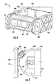
- FIG. 6 is a perspective view of a first end of the controllable insert in FIG. 5 according to one invention.
- FIG. 7 is a side view of a second end of the controllable insert in FIG. 5 according to one invention.
- FIG. 8 is an inside perspective view of a shell and latch according to one invention.
- Medical items such as medications, medical instruments and applicators, may require controlled-access storage to inhibit misuse, mistake, or theft.
- doctors, nurses, technicians, pharmacists, and the like may utilize medication cabinetry specifically designed to securely store and/or controllably distribute medical items, instruments, articles, products, and the like.
- a preferred embodiment of the present invention provides storage for which to securely store such items, where the cabinetry provides selectable access to the contents of drawers. While certain preferred embodiments of the invention may be specifically intended for use with medication cabinetry, it should be noted that the claimed technology can also be used in a variety of other secured-storage applications, such as by jewelers storing jewelry, weapons magazine operators storing ammunition, chemists storing chemicals, bankers storing contents of safe deposit boxes, and the like.
- FIG. 1 presents a diagram of an exemplary embodiment of an item management system 10 (also called a dispensing station).
- a system 10 may, for example, serve as a controlled-access medication system.
- the system 10 includes an electronic control system 14 that is coupled to a cabinet hardware 16 .
- the system 10 allows a system user to interact with the cabinet hardware 16 through the electronic control system 14 .
- an authorized user may direct the electronic control system 14 to release locks in the cabinet hardware 16 , such that contents stored within the cabinetry 16 may be accessed by the authorized user.
- the control system 14 in FIG. 1 further includes a number of components coupled to a controller 20 , such as a user interface 22 (also called a terminal), a software 24 with a memory.
- the user interface 22 relays information signals between a user and controller 20 .
- the software 24 provides ordered logical algorithms used by the controller 20 to interact with the user, the memory, and the hardware 16 . Through the control system 14 , the user may manipulate portions of the cabinet hardware 16 .
- the memory stores data in various databases on a server 30 (or hard drives, disks, and/or the like), including for example a cabinetry-contents information database, an authorization information database, and a client or patient information database.
- a server 30 or hard drives, disks, and/or the like
- One exemplary control system embodiment includes a network of hospital computers, linked to medical patient-related data, medication cabinetry-contents data, and medical personnel authorization data. A user may access, add to, take from, and/or augment the data in the memory.
- other embodiments may not include a memory with databases related to contents, authorization, and/or client information.
- the cabinet hardware 16 in FIG. 1 further includes a drawer unit 50 , a drawer housing 52 , a latch 54 , and an actuator 40 coupled to both a movable access portion 42 of the drawer unit 50 , and a sensor 44 .
- One exemplary movable access portion is a belt with an access opening, wherein the belt is slidable about the drawer unit 50 .
- Another exemplary movable access portion is a flexible cover that bends about the drawer unit, wherein the cover has an opening. The cover flexibly bends in that it is actively bendable, as opposed to fixedly or rigidly bent.
- the system 10 may prevent access to stored items, such as medication.
- Cabinets 90 , 92 are both forms of stationary cabinetry, while cabinet 80 is movable on casters 82 .
- the control system 14 and cabinets 90 , 92 are in wired communication through ports 70 .
- Information is relayed to cabinet 92 through cabinet 90 in a “daisy chain” linkage 74 .
- the control system 14 communicates with cabinet 80 through wireless communication 76 . Additional terminals 72 may also be connected to the server 30 .
- control signals from the controller 20 induce the actuator 40 to move the access portion 42 relative to the drawer unit 50 , from the closed position into an open position.
- Sensory data signals from the sensor 44 may then allow the controller 20 to detect the position and/or orientation of the access portion with respect to the drawer unit 50 .
- the latch 54 holds the drawer unit 50 fully within the drawer housing 52 (i.e., holds the drawer closed), such that a user could not access items within the drawer unit 50 even if the movable access portion 42 was in the open position.
- signals from the controller 20 induce the latch 52 to release the drawer unit 50 , allowing the drawer unit 50 to slide partially out of the drawer housing 52 by the user. With both the drawer unit 50 slid out of the drawer housing 52 and the movable access portion 42 in the open position, the user has access to the selected items.
- FIG. 2 presents an access-controlled cabinetry system 110 , including a cabinetry 112 that is coupled (wireless or hardwired) to a controller 114 via electronic signaling.
- Cabinetry 110 includes a plurality drawer housings 122 sized to hold a plurality of drawer units 120 .
- the drawer units 120 may slide within the drawer housings 122 , such that an authorized user may access the contents of a drawer unit by sliding the drawer unit within the drawer housing to expose an access portion 132 of the drawer unit.
- the controller 114 may emit electronic signals 116 to direct an actuator within the cabinetry 112 to adjust a movable cover 130 on a drawer unit 120 and/or to release a latch binding the drawer unit 120 to the drawer housing 122 .
- a nurse may then slide the drawer unit 120 partially out of the cabinetry drawer housing 122 and then reach into the interior of the drawer unit 120 through the access portion 132 to retrieve a medication item.
- the cabinetry 112 in the system 110 embodiment of FIG. 2 shows individual drawer units 120 and drawer housings 122 in a variety of sizes. In other embodiments, all drawer units and drawer housings are of a uniform size and shape, such that the drawer units are interchangeable within a cabinetry.
- the drawer units 120 in the system 110 are box-shaped. In other embodiments, some drawer units are cylindrical, cubical, hexagonal in cross-section, or other shapes.
- the controller 114 in the FIG. 2 system 110 embodiment is a stand-alone laptop computer.
- the laptop contains software and memory dedicated to the operation of the cabinetry 112 .
- Other controller embodiments include personal computers, computers physically joined to the cabinetry, wireless remote controls (similar to typical television remote controls), hardwired remote controls, data entry ports, control circuitry, circuit boards, and the like.
- Instructions from a user via the controller 114 to the cabinetry 112 may direct a drawer unit 120 to position its cover 130 to allow access to contents stored in compartments within the interior of the drawer unit 120 .
- Additional instructions from the user via the controller 114 to the cabinetry 112 may direct a latch to release an individual drawer unit 120 , such that the drawer unit 120 may be free to slide within a drawer housing 122 in the cabinetry.
- a controller may only control access to a subset of drawer units in a cabinetry. For example, a first controller may control access to a first subset of drawers; a second controller may control access to an overlapping, but larger second subset of drawers; and still third subset of drawers may not be affected by either controller.
- FIG. 3 shows a drawer assembly 210 of drawer units 212 attached to a back wall 214 of cabinetry, where the drawer assembly 210 is analogous to a row 140 shown in the cabinetry 112 of FIG. 2 .
- the drawer assembly 210 in FIG. 3 includes eight drawer units 212 of uniform size and shape in two rows (or four columns), where each drawer unit 212 includes a face 224 and a slidable cover 220 with an opening 222 .
- the drawer unit 212 further includes a plurality of walls 230 that form a drawer unit interior 232 with individual compartments 234 .
- the cover 220 may only be controllably slid when the drawer unit 212 is fully in a drawer housing.
- spring-loaded connection pins separate drawer unit connectivity from the back wall 214 and electrical power is cut to an actuator attached to the cover 220 .
- electrical power is not cut, but a signal directs the actuator not to slide the cover 220 .
- the drawer assembly in FIG. 3 may be retrofit and inserted in place of an older drawer assembly.
- the cover 220 forms a closure over the drawer unit interior compartments 234 , such that the cover 220 may block a user trying to reach the contents of a first compartment (not shown, because it would be beneath the cover 220 in FIG. 3 ).
- the opening 222 of the cover may allow the user access to a second compartment 234 .
- the cover 220 then can be slid by an actuator, repositioning the cover's opening 222 to instead allow access to the first compartment and form a closure with the second compartment. In other positions, the cover 220 may form a closure with both openings.
- the back wall 214 includes circuitry board 240 (also called firmware, e.g., PROM) and a latch actuator 242 (e.g., a solenoid; motor with a pulley; mating electromagnets biased apart; and the like), both coupled to a controller that is analogous to the controller 114 in FIG. 2 .
- the drawer unit 212 may slide along a slide rail 244 that extends from the back wall 214 , to slide relative to a drawer housing. However a latch attached to the back wall 214 may prohibit such sliding when the drawer unit is locked within a drawer housing (i.e., the latch may hold the drawer closed).
- the latch actuator 242 may then release the latch when directed by the controller.
- the back wall 214 may also include an interlock (e.g., a switch, spring pin connection, and the like) that can break electronic communication between the controller and the drawer unit 212 when the drawer unit 212 is partially slid outside a drawer housing such that a substantial portion of the drawer unit 212 is not located within the drawer housing.
- the portion is “substantial” when an unauthorized user could grip and pull the drawer unit 212 and/or cover in order to force access to interior compartments 234 .
- FIG. 4 shows an exploded view of a drawer unit 310 , including three components: a drawer top frame 312 (also called a shell cover), a controllable insert 314 , and a drawer shell 316 (also called a drawer body).
- the insert 314 fits primarily within the shell 316
- the frame with flanges fits over the top of the insert 314 and attaches to the shell 316 in order to prevent removal of the insert from the shell 316 .
- the frame 312 can be tightened to the shell 316 by means of turning a thumb screw.
- the drawer shell 316 is sized to fit within a drawer housing, in a manner analogous to the drawer unit 120 and drawer housing 122 in FIG. 2 .
- the insert 314 includes a slidable cover 320 , a sidewall 322 , and a pair of rollers 324 .
- the cover 320 may slide relative to the drawer unit 310 (i.e., components of the drawer unit other than the cover 320 ).
- the insert 314 includes intermediary flanges extending from the insert sidewall 322 to contact the shell 316 in order to separate the insert cover 320 from contact with the shell 316 . In other embodiments intermediary flanges extend from the shell.
- FIG. 5 shows an exploded, perspective view of a controllable insert 410 , including two components: a belt 412 and an insert body 414 .
- the body 414 includes a plurality of walls, such as dividers 430 , 432 , and side walls 420 , that together form an interior 422 of the body with four compartments 424 . Items may be stored in the compartments 424 .
- Each longitudinal end 440 of the insert 414 includes a roller 440 , where the roller 440 is in the form of a sprocket 442 with teeth 444 that are attached to the sides of each roller 440 .
- the belt 412 includes two perforated tracks 454 , one on each transverse side of the belt 412 .
- the belt 412 is sized to fit around the insert 414 , such that rotation of the sprockets 442 , with the teeth 444 tracking the belt 412 perforations, causes the belt 412 to slide relative to the compartments 424 .
- the belt 412 includes two openings, a larger opening 450 and a smaller opening 452 .
- some of the dividers 430 , 432 are fixed dividers 430 while other dividers are removable dividers 432 providing an optional wall.
- Fixed dividers 430 may be injection molded with the insert body 414 , glued, welded, etc. to the body 414 .
- Removable dividers 432 may be taken out of the insert 410 interior 422 in order to produce a larger compartment (e.g., a compartment formed when a divider 432 is removed).
- the larger opening 450 is sized to fit a larger compartment 424
- the smaller opening 452 is sized to fit a smaller compartment 424 .
- the insert 414 can have either two, three, or four compartments 424 , depending upon the use or removal of the removable inserts 432 .
- FIG. 5 embodiment shows four compartments 424
- other insert body embodiments include fewer or greater numbers of compartments.
- variant embodiment insert bodies have ranges of one to a thousand compartments (e.g., for a long insert with single item access to one-thousand small items), but preferably between one and ten compartments, and even more preferably between one and four compartments, such as the four-compartmented embodiment insert body 410 shown in FIG. 5 .
- the walls 420 form compartments 424 , each with an open side.
- some compartments may include a lid. Some lids may be attached to a wall by a hinge, while other lids may be completely separable from the walls. When the slidable cover (or belt) positions an opening over the lid, the lid may be lifted allowing access to the contents of the compartment.
- the belt 412 which in some embodiments may be an indexing belt and/or a shutter.
- the belt 412 is made of a continuous material, such as about a 0.125 millimeter (or 0.005 inch) thick stainless steel sheet.
- Other embodiments include belts of a thicker clear mylar or polycarbonate sheet.
- Some embodiments include belts made from links, similar to the treads of a tank or the bands of some metal watches.
- the covers are preferably made to be flexible, such that they may bend about a portion of the insert, such as a roller. Bending of the cover allows for a more-compact design, because the unused portions of the cover may be stored beneath or inside the insert, instead of jutting out from the insert.
- belts are sized to be much larger than the periphery of the insert, such that an excess length of belt is stretched back and forth beneath the insert via a series of rollers (much like a rope would extend back and forth in a pulley system or a block and tackle).
- the excess length of belt allows for additional openings of various sizes.
- Still other embodiments include flexible covers that are not belts.
- some embodiments include rollers that are spools that wind the cover within or around the spool. Such covers are straps, strips, bands, and the like, and do not slide completely around the insert.
- Some embodiment covers form openings with reinforced cross edges, such as a folded-over stainless steel cover. The reinforcement can prevent sharp opening edges and help prevent unauthorized “fishing” between compartments, where a user has access to one compartment but then “fishes” by lifting the belt to reach items in an adjacent compartment.
- the sprockets 442 in FIG. 5 include teeth 444 for gripping the perforated belt track.
- Some embodiments include sprockets 442 injection molded from Celcon or Delrin materials, while other embodiments are cast or molded metals and composites.
- the sprocket surfaces have a high-friction surface, such as sandpaper grit or a gripping rubber, for providing the sliding force on the belt (or other cover) without teeth.
- Other embodiments include fixed rollers, such as rounded and/or lower-friction surfaces, such as a rounded Teflon-coated end.
- teeth may prevent misuse of the drawer unit by an unauthorized user pulling the cover to move a cover opening over a desired compartment.
- a lock to the belt, such as a locking member that engages a belt perforation when the drawer unit is slid from its drawer housing, such as a spring latch.
- Some embodiments do not use rollers to impart a sliding force on the cover, but instead use mechanical arms with hooks attached the sides of the belt. The mechanical arms are actuated by electromagnets that pull or push the arms and/or solenoids (i.e., forms of electric actuator), causing the cover to slide relative to the compartments.
- Such embodiments may also use wheels, bearings, sprockets, and the like in conjunction with the arms.
- the controller can drive the actuator in two directions (i.e., bi-directional movement). Bi-directional movement of the cover may allow for faster positioning of a cover opening than uni-directional sliding.
- FIG. 6 shows a perspective view of a first end of the controllable insert 414 , including sidewalls 434 and removable divider 432 forming an interior 422 , two sprockets 442 , and an end surface 460 (that was not shown in FIG. 5 because it would have been beneath the end covers 440 ).
- the end surface forms a motor box 462 in which a DC motor 470 and gearing 472 are positioned.
- the DC motor 470 is coupled to the gearing 472 by a motor shaft (not shown), and the gearing 472 is coupled to a sprocket 442 .
- the motor 470 is also coupled to a controller, and the motor performs as an actuator under the direction of the controller to drive the sprocket, which pushes or pulls the cover 440 .
- the motor 470 is coupled to a power source.
- a source could be an internal battery; a series of copper leads running through the insert connected to an outside source, such as an outlet; or the like.
- an arm connected to an electromagnet could also be an actuator to push or pull the belt, as discussed above.
- the gearing 472 is in the form of a high-reduction gear box that resists movement when not actuated, which may help to prevent unauthorized users from being able to manually force the cover open.
- FIG. 7 shows a side cross-sectional view (as indicated in FIG. 3 ) of a second side of the controllable insert 414 , including, a belt 412 (or other cover), a sprocket 442 with teeth 444 , and a side wall 434 .
- a belt tensioning assembly 480 with tighteners 482 and a sensor assembly 490 which includes an optical sensor 492 attached to the back wall 496 on one side of the belt 412 and a light source 494 on the other side of the belt.
- the tensioning assembly 480 allows for removal and tensioning of the belt 412 on the insert 414 .
- the sensor assembly provides belt 412 orientation information to a controller, so that the controller may operate a motor (or other actuator) in relation to a current and/or desired orientation of the belt 412 and a belt opening.
- FIG. 7 shows a form of tensioning assembly 480 .
- Tighteners 482 e.g., screws; crisscrossing arms, i.e. similar to a jack to raise a car's chassis for repairing tires; a pulley system; and the like
- Tighteners 482 can be tightened or loosed to push the sprockets 442 (or an entire insert 414 end) closer or further from the controllable insert 414 center.
- actuating the tighteners 482 pushes the sprockets 442 further from the center of the insert 414 , thus adding tension to the belt (or other cover).
- a belt 412 with greater tension may help to prevent “fishing” between compartments.
- Tension in the belt also may help the sprocket 442 and teeth 444 to engage and grip the belt 412 .
- Other embodiment tensioning assemblies include springs in place of tighteners, where the sprockets must be manually pushed toward the center of the insert in order to fit the belt onto the insert. Then, when the belt is in position, the sprockets can be released and the springs add tension to the belt through the sprockets.
- Still other embodiment tensioning assemblies include automated tighteners, where a controller directs an actuator to drive the sprockets or insert ends to add tension to the belt.
- FIG. 7 shows a form of sensor assembly 490 that provides belt position information to the controller.
- light passes from the light source 494 (e.g., light-emitting diodes, bulbs, etc.) through evenly-spaced perforations or apertures in the belt to the light sensor 492 .
- the controller then counts the number of perforations detected by the sensor 492 to determine the relative position of the belt 412 .
- the belt includes a series of small holes that are in coded sequences. The coded sequence varies at different positions on the belt, such that detection of the coded sequence by the sensor provides positional information to a controller.
- Still other embodiments do not include an optical sensor for detecting belt position. For example, at least one embodiment counts the rotations of the sprockets, and determines the orientation of the belt relative to a starting position (e.g., “counting teeth” of the sprocket).
- FIG. 8 shows an inside perspective view of a shell 510 coupled to the back wall 512 of a cabinetry.
- a latch arm 520 is positioned beneath the bottom wall 530 of the shell 510 and a latch head 522 connects to the shell 510 through a gripping hole 532 (also called an internal strike) formed within the shell floor 530 .
- the internal strike 532 is reinforced, such as with an overlapping metal border fixed to the shell floor 530 .
- the latch connects to a strike coupled to the outside of the shell.
- the latch arm 520 is coupled a latch actuator 514 that can be directed by a controller to release the latch, i.e. remove the latch head 522 from the hole 532 .
- the latch arm 520 is attached to a spring or other biasing member and automatically engages the shell 510 when the shell gripping hole 532 is placed over the latch head 522 .
- the latch may help prevent an unauthorized user from being able to slide a drawer unit within a drawer housing of a controlled-access cabinetry.
- the user may have the latch released via directions from the controller (i.e., the drawer unit unlocked from the cabinetry).
- Still other embodiments automatically unlock the drawer unit, without direct user instruction, when an authorized user may access the contents of the cabinetry.
- FIG. 4 is a security deflection tab 310 (also called a “fishability bracket”) to block misuse of the cabinetry by manipulating the latch from an above position, such as by drilling a hole in the top of a cabinet and reaching down through the hole with a rod to release the latch.
- FIG. 8 also shows a fishability bracket 540 extending downward from the gripping hole 532 to block fishing from the front of the cabinetry.
- Other embodiments include deflection tabs extending from the shell 510 .
- FIG. 8 shows a manual release plate 542 to release the latch 520 manually from the outside of cabinetry with key, code, and/or the like, such as during a power outage or with a controller malfunction.
- coupling means the joining of two members directly or indirectly to one another. Such joining may be stationary in nature or moveable in nature and/or such joining may allow for the flow of electricity, electrical signals, or other types of signals or communication between two members. Such joining may be achieved with the two members or the two members and any additional intermediate members being integrally formed as a single unitary body with one another or with the two members or the two members and any additional intermediate members being attached to one another. Such joining may be permanent in nature or alternatively may be removable or releasable in nature. In the context of the controller and actuator, coupling generally means coupling components in electric signal communication.
- the cabinetry may be used on a mobile cart with casters and an independent power supply (e.g., battery) such that it can be pushed by nurses to hospital rooms.
- an independent power supply e.g., battery
Abstract
Description
Claims (12)
Priority Applications (26)
| Application Number | Priority Date | Filing Date | Title |
|---|---|---|---|
| US12/351,679 US8103379B2 (en) | 2009-01-09 | 2009-01-09 | Medication cabinetry |
| EP09838015.7A EP2381814B1 (en) | 2009-01-09 | 2009-12-23 | Medication cabinetry |
| EP17159880.8A EP3195758B1 (en) | 2009-01-09 | 2009-12-23 | Medication cabinetry |
| CN201510441691.3A CN105069915B (en) | 2009-01-09 | 2009-12-23 | Medical locker |
| AU2009335680A AU2009335680B2 (en) | 2009-01-09 | 2009-12-23 | Medication cabinetry |
| PCT/US2009/069432 WO2010080660A2 (en) | 2009-01-09 | 2009-12-23 | Medication cabinetry |
| CN200980156356.1A CN102438484B (en) | 2009-01-09 | 2009-12-23 | Medical locker |
| CA2749002A CA2749002C (en) | 2009-01-09 | 2009-12-23 | Medication cabinetry |
| CA2896353A CA2896353C (en) | 2009-01-09 | 2009-12-23 | Medication cabinet with drawer for selectable access |
| BRPI0924190A BRPI0924190A2 (en) | 2009-01-09 | 2009-12-23 | medication cabinet, drawer set and dispensing system |
| JP2011545369A JP5607072B2 (en) | 2009-01-09 | 2009-12-23 | Pharmaceutical cabinet |
| US13/032,753 US8588966B2 (en) | 2009-01-09 | 2011-02-23 | Cabinet system |
| US13/040,931 US9121197B2 (en) | 2009-01-09 | 2011-03-04 | Cabinet system with improved drawer security |
| US13/087,070 US8744621B2 (en) | 2009-01-09 | 2011-04-14 | Medical cabinet access belt optimization system |
| US13/329,787 US9111408B2 (en) | 2009-01-09 | 2011-12-19 | Medication cabinetry |
| US14/054,480 US9245405B2 (en) | 2009-01-09 | 2013-10-15 | Cabinet system |
| JP2014049171A JP5710040B2 (en) | 2009-01-09 | 2014-03-12 | Pharmaceutical cabinet |
| US14/256,740 US9345644B2 (en) | 2009-01-09 | 2014-04-18 | Medical cabinet access belt optimization system |
| JP2015040191A JP6026579B2 (en) | 2009-01-09 | 2015-03-02 | Pharmaceutical cabinet |
| US14/792,347 US9888774B2 (en) | 2009-01-09 | 2015-07-06 | Medication cabinetry |
| US14/805,966 US9770106B2 (en) | 2009-01-09 | 2015-07-22 | Cabinet system with improved drawer security |
| US14/969,370 US9536055B2 (en) | 2009-01-09 | 2015-12-15 | Cabinet system |
| US15/072,008 US9511001B2 (en) | 2009-01-09 | 2016-03-16 | Medical cabinet access belt optimization system |
| US15/295,706 US9925123B2 (en) | 2009-01-09 | 2016-10-17 | Medical cabinet access belt optimization system |
| US15/891,937 US10123944B2 (en) | 2009-01-09 | 2018-02-08 | Medical cabinet access belt optimization system |
| US16/157,936 US10342740B2 (en) | 2009-01-09 | 2018-10-11 | Medical cabinet access belt optimization system |
Applications Claiming Priority (1)
| Application Number | Priority Date | Filing Date | Title |
|---|---|---|---|
| US12/351,679 US8103379B2 (en) | 2009-01-09 | 2009-01-09 | Medication cabinetry |
Related Child Applications (2)
| Application Number | Title | Priority Date | Filing Date |
|---|---|---|---|
| US13/032,753 Continuation-In-Part US8588966B2 (en) | 2009-01-09 | 2011-02-23 | Cabinet system |
| US13/329,787 Continuation US9111408B2 (en) | 2009-01-09 | 2011-12-19 | Medication cabinetry |
Publications (2)
| Publication Number | Publication Date |
|---|---|
| US20100176699A1 US20100176699A1 (en) | 2010-07-15 |
| US8103379B2 true US8103379B2 (en) | 2012-01-24 |
Family
ID=42317084
Family Applications (3)
| Application Number | Title | Priority Date | Filing Date |
|---|---|---|---|
| US12/351,679 Active 2030-02-12 US8103379B2 (en) | 2009-01-09 | 2009-01-09 | Medication cabinetry |
| US13/329,787 Active 2029-05-18 US9111408B2 (en) | 2009-01-09 | 2011-12-19 | Medication cabinetry |
| US14/792,347 Active US9888774B2 (en) | 2009-01-09 | 2015-07-06 | Medication cabinetry |
Family Applications After (2)
| Application Number | Title | Priority Date | Filing Date |
|---|---|---|---|
| US13/329,787 Active 2029-05-18 US9111408B2 (en) | 2009-01-09 | 2011-12-19 | Medication cabinetry |
| US14/792,347 Active US9888774B2 (en) | 2009-01-09 | 2015-07-06 | Medication cabinetry |
Country Status (8)
| Country | Link |
|---|---|
| US (3) | US8103379B2 (en) |
| EP (2) | EP3195758B1 (en) |
| JP (3) | JP5607072B2 (en) |
| CN (2) | CN105069915B (en) |
| AU (1) | AU2009335680B2 (en) |
| BR (1) | BRPI0924190A2 (en) |
| CA (2) | CA2749002C (en) |
| WO (1) | WO2010080660A2 (en) |
Cited By (53)
| Publication number | Priority date | Publication date | Assignee | Title |
|---|---|---|---|---|
| US20090108017A1 (en) * | 2007-02-09 | 2009-04-30 | Cerner Innovation, Inc. | Medication dispensing apparatus with bulk bin loading |
| US20110140831A1 (en) * | 2009-01-09 | 2011-06-16 | Automed Technologies, Inc. | Cabinet System |
| US20110156560A1 (en) * | 2009-01-09 | 2011-06-30 | Automed Technologies, Inc. | Cabinet system with improved drawer security |
| US20110196538A1 (en) * | 2009-01-09 | 2011-08-11 | Automed Technologies, Inc. | Medical cabinet access belt optimization system |
| US20120004772A1 (en) * | 2010-06-30 | 2012-01-05 | Carefusion 303, Inc. | Multi-lidded dispensing cartridge system |
| US20120089248A1 (en) * | 2009-01-09 | 2012-04-12 | Automed Technologies, Inc. | Medication cabinetry |
| US20120232692A1 (en) * | 2011-03-11 | 2012-09-13 | Jane Win-Shih Liu | Local access delivery control system |
| US20130038184A1 (en) * | 2010-04-19 | 2013-02-14 | Development Support Systems Pty Ltd | Spice Rack |
| US20130113344A1 (en) * | 2009-12-17 | 2013-05-09 | Jon Elwell | Secure storage unit |
| WO2013142351A1 (en) * | 2012-03-20 | 2013-09-26 | Intermetro Industries Corporation | Medication dispensing apparatus having drawer assembly with discrete compartments |
| US8650042B2 (en) * | 2011-09-30 | 2014-02-11 | Mckesson Automation Inc. | Case and medication tracking |
| US8662606B2 (en) * | 2011-03-17 | 2014-03-04 | Mckesson Automation Inc. | Drawer assembly and associated method for controllably limiting the slideable extension of a drawer |
| US9081887B2 (en) | 2013-03-15 | 2015-07-14 | Intermetro Industries Corporation | Medication storage and dispensing apparatus having linear drawer assembly including discrete storage modules |
| US9150119B2 (en) | 2013-03-15 | 2015-10-06 | Aesynt Incorporated | Apparatuses, systems, and methods for anticipating and delivering medications from a central pharmacy to a patient using a track based transport system |
| US9195804B2 (en) | 2012-12-06 | 2015-11-24 | S & S X-Ray Products | Daisy chain array of medications cabinets |
| US9511945B2 (en) | 2012-10-12 | 2016-12-06 | Aesynt Incorporated | Apparatuses, systems, and methods for transporting medications from a central pharmacy to a patient in a healthcare facility |
| US20170096285A1 (en) * | 2013-03-15 | 2017-04-06 | Makefield Llc | Dispensing systems with supplemental functions |
| US9652594B2 (en) | 2013-03-15 | 2017-05-16 | Touchpoint Medical, Inc. | Medication storage and dispensing apparatus having linear drawer assembly including discrete storage modules |
| US9731895B2 (en) | 2013-12-07 | 2017-08-15 | Trumed Systems, Inc. | Automated smart storage of temperature sensitive products |
| US9733012B2 (en) | 2012-08-23 | 2017-08-15 | Trumed Systems, Inc. | Smart storage of temperature sensitive pharmaceuticals |
| US10188890B2 (en) | 2013-12-26 | 2019-01-29 | Icon Health & Fitness, Inc. | Magnetic resistance mechanism in a cable machine |
| US20190088070A1 (en) * | 2017-09-20 | 2019-03-21 | Miteshkumar Ishwarbhai Patel | System and Method for Dispensing Medicine Using a Manual Fill Tray Apparatus |
| US10252109B2 (en) | 2016-05-13 | 2019-04-09 | Icon Health & Fitness, Inc. | Weight platform treadmill |
| US10258828B2 (en) | 2015-01-16 | 2019-04-16 | Icon Health & Fitness, Inc. | Controls for an exercise device |
| US10272317B2 (en) | 2016-03-18 | 2019-04-30 | Icon Health & Fitness, Inc. | Lighted pace feature in a treadmill |
| US10279212B2 (en) | 2013-03-14 | 2019-05-07 | Icon Health & Fitness, Inc. | Strength training apparatus with flywheel and related methods |
| US10293211B2 (en) | 2016-03-18 | 2019-05-21 | Icon Health & Fitness, Inc. | Coordinated weight selection |
| US10343017B2 (en) | 2016-11-01 | 2019-07-09 | Icon Health & Fitness, Inc. | Distance sensor for console positioning |
| US10370175B2 (en) | 2012-07-30 | 2019-08-06 | P.C.O.A. Devices Ltd. | Receptacle for containing and dispensing solid medicinal pills |
| US10376736B2 (en) | 2016-10-12 | 2019-08-13 | Icon Health & Fitness, Inc. | Cooling an exercise device during a dive motor runway condition |
| US10399725B2 (en) | 2012-07-05 | 2019-09-03 | P.C.O.A. Devices Ltd. | Medication dispenser |
| US10426989B2 (en) | 2014-06-09 | 2019-10-01 | Icon Health & Fitness, Inc. | Cable system incorporated into a treadmill |
| US10433612B2 (en) | 2014-03-10 | 2019-10-08 | Icon Health & Fitness, Inc. | Pressure sensor to quantify work |
| US10441844B2 (en) | 2016-07-01 | 2019-10-15 | Icon Health & Fitness, Inc. | Cooling systems and methods for exercise equipment |
| US10441840B2 (en) | 2016-03-18 | 2019-10-15 | Icon Health & Fitness, Inc. | Collapsible strength exercise machine |
| US10449416B2 (en) | 2015-08-26 | 2019-10-22 | Icon Health & Fitness, Inc. | Strength exercise mechanisms |
| US10456332B2 (en) | 2014-06-22 | 2019-10-29 | P.C.O.A. Devices Ltd. | Controlled dosage form-dispensing system |
| US10471299B2 (en) | 2016-07-01 | 2019-11-12 | Icon Health & Fitness, Inc. | Systems and methods for cooling internal exercise equipment components |
| US10493349B2 (en) | 2016-03-18 | 2019-12-03 | Icon Health & Fitness, Inc. | Display on exercise device |
| US10500473B2 (en) | 2016-10-10 | 2019-12-10 | Icon Health & Fitness, Inc. | Console positioning |
| US10543395B2 (en) | 2016-12-05 | 2020-01-28 | Icon Health & Fitness, Inc. | Offsetting treadmill deck weight during operation |
| US10561894B2 (en) | 2016-03-18 | 2020-02-18 | Icon Health & Fitness, Inc. | Treadmill with removable supports |
| US10625137B2 (en) | 2016-03-18 | 2020-04-21 | Icon Health & Fitness, Inc. | Coordinated displays in an exercise device |
| US10633135B2 (en) | 2014-08-05 | 2020-04-28 | Hero Health, Inc. | Dispensable unit retrieval mechanism |
| US10661114B2 (en) | 2016-11-01 | 2020-05-26 | Icon Health & Fitness, Inc. | Body weight lift mechanism on treadmill |
| US10729965B2 (en) | 2017-12-22 | 2020-08-04 | Icon Health & Fitness, Inc. | Audible belt guide in a treadmill |
| US10751239B2 (en) | 2015-11-13 | 2020-08-25 | Humanscale Corporation | Medical technology station and method of use |
| US10940360B2 (en) | 2015-08-26 | 2021-03-09 | Icon Health & Fitness, Inc. | Strength exercise mechanisms |
| US10953305B2 (en) | 2015-08-26 | 2021-03-23 | Icon Health & Fitness, Inc. | Strength exercise mechanisms |
| US10952928B2 (en) | 2015-04-20 | 2021-03-23 | Dosentrix Ltd. | Medication dispenser depilling mechanism |
| US11264125B2 (en) | 2015-10-15 | 2022-03-01 | Dosentrx, Ltd. | Image recognition-based dosage form dispensers |
| US11451108B2 (en) | 2017-08-16 | 2022-09-20 | Ifit Inc. | Systems and methods for axial impact resistance in electric motors |
| US11458072B2 (en) | 2015-11-02 | 2022-10-04 | Dosentrx Ltd. | Lockable advanceable oral dosage form dispenser containers |
Families Citing this family (32)
| Publication number | Priority date | Publication date | Assignee | Title |
|---|---|---|---|---|
| US8746908B2 (en) | 2010-01-27 | 2014-06-10 | Automed Technologies, Inc. | Medical supply cabinet with lighting features |
| US8361896B2 (en) | 2010-06-25 | 2013-01-29 | Fci | Signal transmission for high speed interconnections |
| US20120012606A1 (en) | 2010-07-14 | 2012-01-19 | Mark Longley | Automated pharmacy system for dispensing unit doses of pharmaceuticals and the like |
| US10896427B2 (en) * | 2011-09-11 | 2021-01-19 | Greg Grinberg | Computer-implemented process for improved delivery of commodities to consumers |
| TWI454208B (en) * | 2011-11-23 | 2014-09-21 | Hon Hai Prec Ind Co Ltd | Sliding apparatus |
| US20130282171A1 (en) * | 2012-04-18 | 2013-10-24 | Jvm Co., Ltd. | Medicine storage apparatus |
| US9098983B2 (en) * | 2012-05-29 | 2015-08-04 | Carefusion 303, Inc. | Single-item-access drawer |
| CN103144889A (en) * | 2012-10-08 | 2013-06-12 | 苏州艾隆科技股份有限公司 | Method and system for indicating medicine storage positions |
| EP2934235A1 (en) * | 2012-12-19 | 2015-10-28 | MPH Production & Service GmbH | Drawer |
| JP5979105B2 (en) * | 2013-09-05 | 2016-08-24 | 株式会社タクテック | Goods storage device |
| KR101480054B1 (en) * | 2013-12-23 | 2015-01-09 | 에이치엠에이치 주식회사 | Automatic medication cabinet |
| CN104003048B (en) * | 2014-05-20 | 2016-08-24 | 无锡瑞巴斯医疗器械有限公司 | A kind of mobile medicine-chest |
| JP6051244B2 (en) * | 2015-02-10 | 2016-12-27 | 株式会社オー・イー・エム技研 | Self-supporting automatic medication machine |
| USD789712S1 (en) * | 2015-05-14 | 2017-06-20 | 3 Strike, Llc | Storage container shelf |
| CN105116806B (en) * | 2015-08-28 | 2019-01-11 | 无锡瑞巴斯医疗器械有限公司 | A kind of nursing station drawer control device |
| NO341502B1 (en) * | 2016-01-14 | 2017-11-27 | Autostore Tech As | Method and system for retrieving an article from a storage bin |
| CN106108431A (en) * | 2016-07-11 | 2016-11-16 | 吴成贵 | A kind of family dual-purpose network intelligent medicine cabinet |
| CN106805528A (en) * | 2017-03-23 | 2017-06-09 | 无锡诺信安全科技有限公司 | It is easy to the chemical reagent cabinet of management |
| AU2018330849A1 (en) * | 2017-09-08 | 2020-03-26 | Vdms Canada Inc. | Dispensing and live inventory management system and methods thereof |
| SG11202003465QA (en) * | 2017-10-17 | 2020-05-28 | Helmer Inc | Undercounter refrigerator with access control |
| CN109841008A (en) * | 2017-11-24 | 2019-06-04 | 颜均颕 | Mechanical five metals material automatic selling system |
| CN108236228B (en) * | 2018-01-15 | 2021-09-28 | 解先念 | Domestic medical equipment case |
| US10413064B1 (en) * | 2018-09-26 | 2019-09-17 | Dong Guan Song Wei Electric Technology Co., Ltd. | Electric drawer with gesture sensing |
| NO344988B1 (en) * | 2018-11-05 | 2020-08-10 | Autostore Tech As | A station for providing access to contents in a storage container |
| CN110250756A (en) * | 2019-07-08 | 2019-09-20 | 西安石油大学 | A kind of Intelligent cabinet based on PLC control |
| TWI710338B (en) * | 2019-07-15 | 2020-11-21 | 彰化基督教醫療財團法人彰化基督教醫院 | Intelligent electromagnetic storage cabinet |
| CN110840747B (en) * | 2019-11-28 | 2021-10-01 | 安徽全康药业有限公司 | Pelleting device for making eucommia male flower pills and preparation method thereof |
| US11615875B2 (en) | 2020-03-30 | 2023-03-28 | Omnicell, Inc. | Sensor driven secure dispensing unit |
| EP3901633B1 (en) * | 2020-04-22 | 2022-08-17 | Roche Diagnostics GmbH | A laboratory sample vessel distribution system, a method for operating, and an in-vitro diagnostic system |
| CN111920226B (en) * | 2020-08-27 | 2021-10-01 | 杨建飞 | Intelligent traditional Chinese medicine cabinet |
| CN112869420B (en) * | 2021-02-22 | 2023-01-31 | 台山平安五金制品有限公司 | Intelligent online safe deposit box and management system thereof |
| WO2023170680A1 (en) | 2022-03-08 | 2023-09-14 | Equashield Medical Ltd | Fluid transfer station in a robotic pharmaceutical preparation system |
Citations (57)
| Publication number | Priority date | Publication date | Assignee | Title |
|---|---|---|---|---|
| US3682113A (en) * | 1971-01-25 | 1972-08-08 | Meilink Steel Safe Co | Deal drawer |
| US4267942A (en) | 1979-06-20 | 1981-05-19 | John B. Wick, Jr. | Pharmaceutical dispensing cabinet |
| US4785969A (en) | 1986-11-10 | 1988-11-22 | Pyxis Corporation | Medication dispensing system |
| US4865404A (en) | 1988-07-18 | 1989-09-12 | Harpers | Interlock for multi-drawer cabinet |
| US4927051A (en) | 1987-10-26 | 1990-05-22 | Unidynamics Corporation | Multiple-product merchandising machine |
| US5014875A (en) | 1989-03-01 | 1991-05-14 | Pyxis Corporation | Medication dispenser station |
| US5222789A (en) * | 1990-11-29 | 1993-06-29 | Koichi Yoshikawa | Drawer system |
| US5255971A (en) | 1990-08-31 | 1993-10-26 | Zaca Inc. | Medicine cabinet |
| US5377864A (en) | 1989-05-25 | 1995-01-03 | Baxter International Inc. | Drug dispensing apparatus |
| US5405048A (en) | 1993-06-22 | 1995-04-11 | Kvm Technologies, Inc. | Vacuum operated medicine dispenser |
| US5460294A (en) | 1994-05-12 | 1995-10-24 | Pyxis Corporation | Single dose pharmaceutical dispenser subassembly |
| US5745366A (en) | 1994-07-14 | 1998-04-28 | Omnicell Technologies, Inc. | Pharmaceutical dispensing device and methods |
| US5805456A (en) | 1994-07-14 | 1998-09-08 | Omnicell Technologies, Inc. | Device and method for providing access to items to be dispensed |
| US5905653A (en) | 1994-07-14 | 1999-05-18 | Omnicell Technologies, Inc. | Methods and devices for dispensing pharmaceutical and medical supply items |
| US5927540A (en) * | 1997-08-20 | 1999-07-27 | Omnicell Technologies, Inc. | Controlled dispensing system and method |
| US6011999A (en) | 1997-12-05 | 2000-01-04 | Omnicell Technologies, Inc. | Apparatus for controlled dispensing of pharmaceutical and medical supplies |
| US6109774A (en) | 1995-08-01 | 2000-08-29 | Pyxis Corporation | Drawer operating system |
| US6116461A (en) | 1998-05-29 | 2000-09-12 | Pyxis Corporation | Method and apparatus for the dispensing of drugs |
| US6151536A (en) | 1998-09-28 | 2000-11-21 | Omnicell.Com | Dispensing system and methods |
| US6170929B1 (en) | 1998-12-02 | 2001-01-09 | Ronald H. Wilson | Automated medication-dispensing cart |
| US6175779B1 (en) | 1998-09-29 | 2001-01-16 | J. Todd Barrett | Computerized unit dose medication dispensing cart |
| US20010019065A1 (en) | 1997-12-05 | 2001-09-06 | William Jeffrey P. | Pill dispensing system |
| JP2001275766A (en) | 2000-03-31 | 2001-10-09 | Kyoei Ind Co Ltd | Cabinet with device latching safely |
| US20010044731A1 (en) | 2000-05-18 | 2001-11-22 | Coffman Damon J. | Distributed remote asset and medication management drug delivery system |
| US6401991B1 (en) | 2001-02-15 | 2002-06-11 | Kathleen H. Eannone | Computer timed-locked medication container with individual compartments |
| US6427865B1 (en) | 1998-04-15 | 2002-08-06 | Kenneth Stillwell | Automatic pill dispenser |
| US6594549B2 (en) | 2001-04-04 | 2003-07-15 | Bruce Siegel | Web-enabled medication dispenser |
| US6609047B1 (en) | 1993-07-21 | 2003-08-19 | Omnicell Technologies, Inc. | Methods and apparatus for dispensing items |
| US6662081B1 (en) | 2000-06-08 | 2003-12-09 | Medport Llc | Medication regimen container and system |
| US20040026442A1 (en) | 2002-08-09 | 2004-02-12 | Mckesson Automation Sys Inc | Vacuum pill dispensing cassette and counting machine |
| US6760643B2 (en) | 1994-10-11 | 2004-07-06 | Omnicell, Inc. | Methods and apparatus for dispensing items |
| US20040134043A1 (en) | 2002-12-25 | 2004-07-15 | Sanyo Electric Co., Ltd. | Medicine supply apparatus |
| US20040158350A1 (en) * | 2001-05-15 | 2004-08-12 | Jens Ostergaard | Medicine dispenser |
| US6785589B2 (en) | 2001-11-30 | 2004-08-31 | Mckesson Automation, Inc. | Dispensing cabinet with unit dose dispensing drawer |
| US6847861B2 (en) | 2001-11-30 | 2005-01-25 | Mckesson Automation, Inc. | Carousel product for use in integrated restocking and dispensing system |
| US20050145644A1 (en) | 2002-02-20 | 2005-07-07 | Sanyo Electric Co., Ltd. | Chemical feeding device |
| US6975922B2 (en) | 2003-05-08 | 2005-12-13 | Omnicell, Inc. | Secured dispensing cabinet and methods |
| US6997377B2 (en) * | 2002-12-31 | 2006-02-14 | Diebold Self-Service Systems Division Of Diebold, Incorporated | ATM cassette with self-locking media directing guide |
| US20060079994A1 (en) | 2004-10-08 | 2006-04-13 | Chu Woei C | Unit-dose medication dispensing cart and method of operating the same |
| US20060151517A1 (en) * | 2002-08-21 | 2006-07-13 | Reijo Varis | Device for dispensing tablet-or capsule-shaped medicaments in desired doses |
| US20060197419A1 (en) * | 2005-03-03 | 2006-09-07 | Sorensen Robert J | Overhead storage device |
| US20070023193A1 (en) | 2003-09-17 | 2007-02-01 | King Roy D | Inventory control system |
| US20070078562A1 (en) | 2005-10-03 | 2007-04-05 | Sabal Medical, Inc. | Mobile medication storage and dispensing apparatus |
| US7228200B2 (en) | 2004-04-22 | 2007-06-05 | Parata Systems, Llc | Apparatus, system and methods for dispensing products |
| US7293673B2 (en) | 2004-09-08 | 2007-11-13 | Supplypro, Inc. | Drawer item dispenser |
| US20070262147A1 (en) | 2006-05-10 | 2007-11-15 | Mckesson Automation Inc. | System, method and corresponding apparatus for storing, retrieving and delivering unit dose blisters |
| US20080065264A1 (en) | 2004-09-03 | 2008-03-13 | Tosho Inc. | Medical Resource Storage and Management Apparatus and Medical Supply Management System |
| US20080129171A1 (en) | 2002-02-06 | 2008-06-05 | Lori Greiner | Jewelry organizer |
| US7395945B2 (en) | 2004-09-24 | 2008-07-08 | Nexiant | Controlled dispensing system with modular carousel |
| US7434704B2 (en) | 2002-08-05 | 2008-10-14 | Yuyama Mfg. Co., Ltd. | Medicine feeder |
| US7464832B2 (en) * | 2003-12-31 | 2008-12-16 | Lg N-Sys Inc. | Media cassette with internal lock |
| US20090015116A1 (en) | 2003-02-24 | 2009-01-15 | Rubbermaid Commercial Products, Llc | Medical cart, medication module, height adjustment mechanism, and method of medication transport |
| US20090055018A1 (en) | 2002-12-06 | 2009-02-26 | Mckesson Automation Inc. | High capacity drawer with mechanical indicator for a dispensing device |
| US7502666B2 (en) | 2004-05-14 | 2009-03-10 | Mts Medication Technologies, Inc. | Systems and methods for storing and dispensing medication |
| US20090108016A1 (en) | 2007-10-30 | 2009-04-30 | Cardinal Health 303, Inc. | Secure medication transport and administration system |
| US20090114672A1 (en) | 2007-02-09 | 2009-05-07 | Cerner Innovation, Inc. | Medication dispensing apparatus for dispensing single items from multiple-compartment bins |
| US20090138122A1 (en) | 2007-11-26 | 2009-05-28 | Wagner David J | Pharmacy medication verification system |
Family Cites Families (102)
| Publication number | Priority date | Publication date | Assignee | Title |
|---|---|---|---|---|
| US1888386A (en) * | 1930-05-09 | 1932-11-22 | Gerh Arehns Mek Verkst Ab | Means for arranging oval cigarettes |
| US2246626A (en) * | 1940-07-06 | 1941-06-24 | William N Grandin | Fly case |
| US2412332A (en) * | 1945-07-27 | 1946-12-10 | Ole Glsvold | Container |
| US3154880A (en) * | 1963-04-30 | 1964-11-03 | Ervin L Cunningham | Container |
| US3286390A (en) * | 1964-09-30 | 1966-11-22 | Frank L Guice | Container |
| US4057145A (en) * | 1976-03-19 | 1977-11-08 | Wray Betty B | Compliance dispenser for oral medication |
| DE2911607C2 (en) * | 1979-03-24 | 1982-04-15 | East Tradacons AG, Steinhausen | Cassette for the protected storage of a set of drills |
| DE3036739A1 (en) | 1980-09-29 | 1982-06-03 | Siemens AG, 1000 Berlin und 8000 München | TELEPHONE MOBILE RADIO SYSTEM FOR DIGITAL VOICE TRANSFER |
| GB8519701D0 (en) * | 1985-08-06 | 1985-09-11 | Videomat Automation Ltd | Dispensing apparatus |
| US4763810A (en) * | 1986-12-19 | 1988-08-16 | Christiansen Lee T | Medication dispenser |
| ATE114846T1 (en) | 1989-01-19 | 1994-12-15 | Mib Elettronica | DEVICE FOR PROTECTING AND PROCESSING BANKNOTES AND VALUABLES. |
| US4941570A (en) * | 1989-04-19 | 1990-07-17 | Easco Hand Tools, Inc. | Wrench socket dispenser |
| AT393956B (en) | 1989-10-20 | 1992-01-10 | Loidl Rudolf | DEVICE FOR STORING AND TIMELY TAKING DRUGS |
| US5046455A (en) * | 1990-12-17 | 1991-09-10 | Christiansen Steven A | Automatic animal feeder |
| US5259668A (en) | 1991-03-01 | 1993-11-09 | Artromick International Inc. | Cart for medication |
| US5282678A (en) | 1991-03-01 | 1994-02-01 | Artromick International, Inc. | Cart for medication |
| US5467266A (en) | 1991-09-03 | 1995-11-14 | Lutron Electronics Co., Inc. | Motor-operated window cover |
| US5263596A (en) | 1991-12-02 | 1993-11-23 | Williams David R | Medication dispenser station sub-assembly |
| US5445295A (en) | 1992-01-17 | 1995-08-29 | Brown; Graham | Automated vending machine system for recorded goods |
| US5211461A (en) | 1992-04-10 | 1993-05-18 | Artromick International, Inc. | Vertically adjustable extension drawers |
| US5346297A (en) | 1993-01-04 | 1994-09-13 | Colson Jr Angus R | Auxiliary storage and dispensing unit |
| US5790409A (en) | 1993-01-25 | 1998-08-04 | Medselect Systems, Inc. | Inventory monitoring and dispensing system for medical items |
| US5404384A (en) | 1993-01-25 | 1995-04-04 | Medselect Systems, Inc. | Inventory monitoring apparatus employing counter for adding and subtracting objects being monitored |
| US5912818A (en) | 1993-01-25 | 1999-06-15 | Diebold, Incorporated | System for tracking and dispensing medical items |
| US5533079A (en) | 1993-01-25 | 1996-07-02 | Medselect Systems, Inc. | Inventory monitoring apparatus |
| US5392951A (en) | 1993-05-20 | 1995-02-28 | Lionville Systems, Inc. | Drawer operating system |
| US5431299A (en) | 1994-01-26 | 1995-07-11 | Andrew E. Brewer | Medication dispensing and storing system with dispensing modules |
| WO1996010240A1 (en) | 1994-09-28 | 1996-04-04 | Kvm Technologies, Inc. | Secure medication storage and retrieval system |
| US5848593A (en) | 1994-12-16 | 1998-12-15 | Diebold, Incorporated | System for dispensing a kit of associated medical items |
| US7349858B1 (en) | 1994-12-16 | 2008-03-25 | Automed Technologies, Inc. | Method of dispensing and tracking the giving of medical items to patients |
| US7467093B1 (en) | 1994-12-16 | 2008-12-16 | Automed Technologies, Inc | Method of tracking and despensing medical items to patients through self service delivery system |
| US8423180B1 (en) | 1994-12-16 | 2013-04-16 | Automed Technologies, Inc. | System for tracking and dispensing medical items from environmentally controlled storage area |
| US5724764A (en) * | 1995-10-10 | 1998-03-10 | Alsup; Charles Kent | Storage box |
| JP4054378B2 (en) * | 1995-10-10 | 2008-02-27 | オムニセル インコーポレイテッド | Drug dispensing apparatus and method |
| US5713485A (en) | 1995-10-18 | 1998-02-03 | Adds, Inc. | Drug dispensing system |
| US5797515A (en) | 1995-10-18 | 1998-08-25 | Adds, Inc. | Method for controlling a drug dispensing system |
| JP3122611B2 (en) | 1996-04-22 | 2001-01-09 | オートメッド テクノロジーズ インコーポレイテッド | Drug packaging machine |
| US5961036A (en) | 1996-07-12 | 1999-10-05 | Diebold, Incorporated | Apparatus and method for accepting return of unused medical items |
| US6378963B1 (en) | 1996-11-04 | 2002-04-30 | Drustar, Inc. | Modular drawer system |
| US6902083B1 (en) | 1997-04-30 | 2005-06-07 | Automed Technologies, Inc. | Method for dispensing medical items |
| US7048142B1 (en) | 1997-04-30 | 2006-05-23 | Automed Technologies, Inc. | Apparatus for dispensing medical items |
| US6019249A (en) | 1997-04-30 | 2000-02-01 | Diebold, Incorporated | Apparatus for dispensing medical items |
| US6776306B1 (en) | 1997-04-30 | 2004-08-17 | Medselect Inc. | Apparatus for dispensing medical items |
| US6788997B1 (en) | 1998-06-01 | 2004-09-07 | Medselect, Inc. | Medical cabinet with adjustable drawers |
| US6256967B1 (en) | 1998-08-27 | 2001-07-10 | Automed Technologies, Inc. | Integrated automated drug dispenser method and apparatus |
| US6170230B1 (en) | 1998-12-04 | 2001-01-09 | Automed Technologies, Inc. | Medication collecting system |
| US6245297B1 (en) * | 1999-04-16 | 2001-06-12 | Pe Corporation (Ny) | Apparatus and method for transferring small volumes of substances |
| US6564121B1 (en) | 1999-09-22 | 2003-05-13 | Telepharmacy Solutions, Inc. | Systems and methods for drug dispensing |
| US7006893B2 (en) | 1999-09-22 | 2006-02-28 | Telepharmacy Solutions, Inc. | Systems for dispensing medical products |
| US7689316B1 (en) | 2000-05-05 | 2010-03-30 | Automed Technologies, Inc. | Medical item storage cabinet and method |
| US7685026B1 (en) | 2000-05-05 | 2010-03-23 | Automed Technologies, Inc. | Method of tracking and dispensing medical items |
| US6658322B1 (en) | 2000-05-05 | 2003-12-02 | Medselect Inc. | System and method for tracking medical items and supplies |
| US7463947B1 (en) | 2000-05-05 | 2008-12-09 | Automed Technologies, Inc. | Medical item storage cabinet and method |
| US7262698B1 (en) | 2000-05-05 | 2007-08-28 | Automed Technologies, Inc. | Medical item storage cabinet and method |
| US7596427B1 (en) | 2000-05-05 | 2009-09-29 | Automed Technologies, Inc. | Medical item storage cabinet and method |
| US6348864B1 (en) | 2000-05-06 | 2002-02-19 | Magnex Corporation | Organizer management system using R.F. identification |
| US6502718B2 (en) | 2001-03-19 | 2003-01-07 | Innovative Product Achievements, Inc. | Garment dispensing and receiving apparatus having a removable cartridge body and a flexible dispensing door |
| US6532399B2 (en) | 2001-06-05 | 2003-03-11 | Baxter International Inc. | Dispensing method using indirect coupling |
| US6746091B2 (en) | 2001-12-05 | 2004-06-08 | Artromick International, Inc. | Cart locking device |
| US6895304B2 (en) | 2001-12-07 | 2005-05-17 | Mckesson Automation, Inc. | Method of operating a dispensing cabinet |
| US6650964B2 (en) | 2002-04-16 | 2003-11-18 | Mckesson Automation Inc. | Medication dispensing apparatus override check and communication system |
| US20030201697A1 (en) * | 2002-04-30 | 2003-10-30 | Richardson William R. | Storage device for health care facility |
| WO2004014189A1 (en) | 2002-08-07 | 2004-02-19 | Supplypro, Inc. | Apparatus for securing drawer contents |
| CA2806483C (en) | 2002-08-09 | 2014-12-09 | Parata Systems, Llc | Dispensing device having a storage chamber, dispensing chamber and a feed regulator there between |
| US20040050750A1 (en) | 2002-09-18 | 2004-03-18 | Hannan Robin E. | Medication cart drawer liner and method for using same to reduce nosocomial infections |
| US6775591B1 (en) * | 2003-01-24 | 2004-08-10 | S&S X-Ray Products, Inc. | Portable medication dispensing unit |
| US8195328B2 (en) | 2003-09-19 | 2012-06-05 | Vesta Medical, Llc | Combination disposal and dispensing apparatus and method |
| JP2005143401A (en) * | 2003-11-17 | 2005-06-09 | Satomi Matoba | Toilet for small animal |
| CA2488955C (en) | 2003-12-05 | 2014-10-07 | Automed Technologies, Inc. | Pharmacy dispensing system and method |
| US7152441B2 (en) | 2004-03-11 | 2006-12-26 | Artromick International, Inc. | Cart locking device |
| JP2005287609A (en) * | 2004-03-31 | 2005-10-20 | Katsutoshi Ando | Multifunctional storage case for notebook computer |
| CN1938725A (en) | 2004-04-01 | 2007-03-28 | 松下电器产业株式会社 | Ticket management system, terminal device, ticket management server, register device, value conversion method, computer program, and recording medium |
| US8121725B2 (en) | 2004-04-22 | 2012-02-21 | Parata Systems, Llc | Apparatus, system and methods for dispensing products |
| CA2507072A1 (en) * | 2004-05-10 | 2005-11-10 | Apg Cash Drawer | Short depth cash drawer with a moveable base |
| US7348884B2 (en) | 2004-07-29 | 2008-03-25 | Omnicell, Inc. | RFID cabinet |
| WO2007035185A2 (en) | 2004-12-03 | 2007-03-29 | Mckesson Automation Inc. | Mobile point of care system and associated method and computer program product |
| US7258241B2 (en) | 2005-03-31 | 2007-08-21 | Amerisourcebergen Drug Corporation | Method and apparatus for facilitating bar-code scanning of rack contents using rack column mounted display |
| JP4626370B2 (en) * | 2005-04-11 | 2011-02-09 | ブラザー工業株式会社 | Image forming apparatus |
| JP4923734B2 (en) * | 2005-05-31 | 2012-04-25 | 株式会社湯山製作所 | Drug packaging device |
| US8231749B2 (en) | 2005-06-02 | 2012-07-31 | Automed Technologies, Inc. | Apparatus and methods for dispensing pre-filled containers with precisely-applied patient-specific information |
| JP2007126270A (en) * | 2005-11-07 | 2007-05-24 | Sumita System:Kk | Picking device |
| US7630791B2 (en) | 2005-12-09 | 2009-12-08 | CareFusion 303 Inc. | System and method for storing items and tracking item usage |
| US7891222B2 (en) | 2006-06-12 | 2011-02-22 | Hafele America Company | Electronic locking system |
| US7637374B2 (en) * | 2007-03-14 | 2009-12-29 | Fried Brian A | Rotating egg container |
| US7823993B2 (en) | 2007-04-03 | 2010-11-02 | Carefusion 303, Inc. | Piezo actuated slide latching mechanism |
| JP4145343B1 (en) * | 2007-06-20 | 2008-09-03 | 有限会社コスモデザイン | Goods management device |
| US8068932B2 (en) * | 2007-08-14 | 2011-11-29 | Roche Diagnostics Operations, Inc. | Access-controlled storage system |
| US7782198B2 (en) | 2007-12-03 | 2010-08-24 | International Business Machines Corporation | Apparatus and method for detecting tampering of a printer compartment |
| US7719420B2 (en) | 2008-02-14 | 2010-05-18 | Mckesson Automation Inc. | Lock status notification and next case medication method, apparatus and corresponding medication storage device |
| US8234008B2 (en) | 2008-02-29 | 2012-07-31 | Carefusion 303, Inc. | Lidded drawer for single line item dispensing |
| GB2461070A (en) | 2008-06-19 | 2009-12-23 | Shafir Production Systems Ltd | Cabinet for handling distributable items comprising drawer access and control system and lockable bins |
| KR100963597B1 (en) | 2008-07-18 | 2010-06-15 | 강연균 | Air tight circulation type storage cabinet for chemical reagents |
| US8103379B2 (en) | 2009-01-09 | 2012-01-24 | Automed Technologies, Inc. | Medication cabinetry |
| US8744621B2 (en) | 2009-01-09 | 2014-06-03 | Automed Technologies, Inc. | Medical cabinet access belt optimization system |
| US9121197B2 (en) | 2009-01-09 | 2015-09-01 | Automed Technologies, Inc. | Cabinet system with improved drawer security |
| US8588966B2 (en) | 2009-01-09 | 2013-11-19 | Automed Technologies, Inc. | Cabinet system |
| US9149405B2 (en) | 2009-03-03 | 2015-10-06 | Aesynt Incorporated | Medication storage and dispensing unit having a vial dispenser |
| US8262174B2 (en) | 2009-06-05 | 2012-09-11 | Carefusion 303, Inc. | Multi-latch release mechanism |
| US8197017B2 (en) | 2009-07-20 | 2012-06-12 | Carefusion 303, Inc. | Rotating multi-latch release mechanism |
| US8746908B2 (en) | 2010-01-27 | 2014-06-10 | Automed Technologies, Inc. | Medical supply cabinet with lighting features |
| US8335588B2 (en) | 2010-06-30 | 2012-12-18 | Carefusion 303, Inc. | Multi-lidded dispensing cartridge system |
| US9243427B2 (en) | 2011-01-24 | 2016-01-26 | Carefusion 303, Inc. | Self-aligning modular latch |
-
2009
- 2009-01-09 US US12/351,679 patent/US8103379B2/en active Active
- 2009-12-23 AU AU2009335680A patent/AU2009335680B2/en active Active
- 2009-12-23 WO PCT/US2009/069432 patent/WO2010080660A2/en active Application Filing
- 2009-12-23 CA CA2749002A patent/CA2749002C/en active Active
- 2009-12-23 EP EP17159880.8A patent/EP3195758B1/en active Active
- 2009-12-23 CN CN201510441691.3A patent/CN105069915B/en active Active
- 2009-12-23 BR BRPI0924190A patent/BRPI0924190A2/en not_active Application Discontinuation
- 2009-12-23 CN CN200980156356.1A patent/CN102438484B/en active Active
- 2009-12-23 JP JP2011545369A patent/JP5607072B2/en active Active
- 2009-12-23 CA CA2896353A patent/CA2896353C/en active Active
- 2009-12-23 EP EP09838015.7A patent/EP2381814B1/en active Active
-
2011
- 2011-12-19 US US13/329,787 patent/US9111408B2/en active Active
-
2014
- 2014-03-12 JP JP2014049171A patent/JP5710040B2/en not_active Expired - Fee Related
-
2015
- 2015-03-02 JP JP2015040191A patent/JP6026579B2/en active Active
- 2015-07-06 US US14/792,347 patent/US9888774B2/en active Active
Patent Citations (65)
| Publication number | Priority date | Publication date | Assignee | Title |
|---|---|---|---|---|
| US3682113A (en) * | 1971-01-25 | 1972-08-08 | Meilink Steel Safe Co | Deal drawer |
| US4267942A (en) | 1979-06-20 | 1981-05-19 | John B. Wick, Jr. | Pharmaceutical dispensing cabinet |
| US4785969A (en) | 1986-11-10 | 1988-11-22 | Pyxis Corporation | Medication dispensing system |
| US4927051A (en) | 1987-10-26 | 1990-05-22 | Unidynamics Corporation | Multiple-product merchandising machine |
| US4865404A (en) | 1988-07-18 | 1989-09-12 | Harpers | Interlock for multi-drawer cabinet |
| US5014875A (en) | 1989-03-01 | 1991-05-14 | Pyxis Corporation | Medication dispenser station |
| US5377864A (en) | 1989-05-25 | 1995-01-03 | Baxter International Inc. | Drug dispensing apparatus |
| US5255971B1 (en) | 1990-08-31 | 1996-12-17 | Zaca Inc | Medicine cabinet |
| US5255971A (en) | 1990-08-31 | 1993-10-26 | Zaca Inc. | Medicine cabinet |
| US5222789A (en) * | 1990-11-29 | 1993-06-29 | Koichi Yoshikawa | Drawer system |
| US5405048A (en) | 1993-06-22 | 1995-04-11 | Kvm Technologies, Inc. | Vacuum operated medicine dispenser |
| US6609047B1 (en) | 1993-07-21 | 2003-08-19 | Omnicell Technologies, Inc. | Methods and apparatus for dispensing items |
| US5460294A (en) | 1994-05-12 | 1995-10-24 | Pyxis Corporation | Single dose pharmaceutical dispenser subassembly |
| US5745366A (en) | 1994-07-14 | 1998-04-28 | Omnicell Technologies, Inc. | Pharmaceutical dispensing device and methods |
| US5905653A (en) | 1994-07-14 | 1999-05-18 | Omnicell Technologies, Inc. | Methods and devices for dispensing pharmaceutical and medical supply items |
| US5805456A (en) | 1994-07-14 | 1998-09-08 | Omnicell Technologies, Inc. | Device and method for providing access to items to be dispensed |
| US6760643B2 (en) | 1994-10-11 | 2004-07-06 | Omnicell, Inc. | Methods and apparatus for dispensing items |
| US6109774A (en) | 1995-08-01 | 2000-08-29 | Pyxis Corporation | Drawer operating system |
| US5927540A (en) * | 1997-08-20 | 1999-07-27 | Omnicell Technologies, Inc. | Controlled dispensing system and method |
| US20010019065A1 (en) | 1997-12-05 | 2001-09-06 | William Jeffrey P. | Pill dispensing system |
| US6011999A (en) | 1997-12-05 | 2000-01-04 | Omnicell Technologies, Inc. | Apparatus for controlled dispensing of pharmaceutical and medical supplies |
| US6427865B1 (en) | 1998-04-15 | 2002-08-06 | Kenneth Stillwell | Automatic pill dispenser |
| US6116461A (en) | 1998-05-29 | 2000-09-12 | Pyxis Corporation | Method and apparatus for the dispensing of drugs |
| US7040504B2 (en) | 1998-05-29 | 2006-05-09 | Cardinal Health 301, Inc. | System and apparatus for the dispensing of drugs |
| US6338007B1 (en) | 1998-05-29 | 2002-01-08 | Pyxis Corporation | System and apparatus for the storage and dispensing of items |
| US6151536A (en) | 1998-09-28 | 2000-11-21 | Omnicell.Com | Dispensing system and methods |
| US6175779B1 (en) | 1998-09-29 | 2001-01-16 | J. Todd Barrett | Computerized unit dose medication dispensing cart |
| US6170929B1 (en) | 1998-12-02 | 2001-01-09 | Ronald H. Wilson | Automated medication-dispensing cart |
| JP2001275766A (en) | 2000-03-31 | 2001-10-09 | Kyoei Ind Co Ltd | Cabinet with device latching safely |
| US20010044731A1 (en) | 2000-05-18 | 2001-11-22 | Coffman Damon J. | Distributed remote asset and medication management drug delivery system |
| US6662081B1 (en) | 2000-06-08 | 2003-12-09 | Medport Llc | Medication regimen container and system |
| US6401991B1 (en) | 2001-02-15 | 2002-06-11 | Kathleen H. Eannone | Computer timed-locked medication container with individual compartments |
| US6594549B2 (en) | 2001-04-04 | 2003-07-15 | Bruce Siegel | Web-enabled medication dispenser |
| US20040158350A1 (en) * | 2001-05-15 | 2004-08-12 | Jens Ostergaard | Medicine dispenser |
| US6785589B2 (en) | 2001-11-30 | 2004-08-31 | Mckesson Automation, Inc. | Dispensing cabinet with unit dose dispensing drawer |
| US6847861B2 (en) | 2001-11-30 | 2005-01-25 | Mckesson Automation, Inc. | Carousel product for use in integrated restocking and dispensing system |
| US6996455B2 (en) | 2001-11-30 | 2006-02-07 | Mckesson Automation Inc. | Dispensing cabinet with unit dose dispensing drawer |
| US7010389B2 (en) | 2001-11-30 | 2006-03-07 | Mckesson Automation, Inc. | Restocking system using a carousel |
| US7072737B2 (en) | 2001-11-30 | 2006-07-04 | Mckesson Automation, Inc. | Filling a restocking package using a carousel |
| US20080129171A1 (en) | 2002-02-06 | 2008-06-05 | Lori Greiner | Jewelry organizer |
| US20050145644A1 (en) | 2002-02-20 | 2005-07-07 | Sanyo Electric Co., Ltd. | Chemical feeding device |
| US7293672B2 (en) | 2002-02-20 | 2007-11-13 | Sanyo Electric Co., Ltd. | Chemical feeding device |
| US7434704B2 (en) | 2002-08-05 | 2008-10-14 | Yuyama Mfg. Co., Ltd. | Medicine feeder |
| US20040026442A1 (en) | 2002-08-09 | 2004-02-12 | Mckesson Automation Sys Inc | Vacuum pill dispensing cassette and counting machine |
| US20060151517A1 (en) * | 2002-08-21 | 2006-07-13 | Reijo Varis | Device for dispensing tablet-or capsule-shaped medicaments in desired doses |
| US20090055018A1 (en) | 2002-12-06 | 2009-02-26 | Mckesson Automation Inc. | High capacity drawer with mechanical indicator for a dispensing device |
| US7848846B2 (en) * | 2002-12-25 | 2010-12-07 | Sanyo Electric Co., Ltd. | Medicine supply apparatus |
| US20040134043A1 (en) | 2002-12-25 | 2004-07-15 | Sanyo Electric Co., Ltd. | Medicine supply apparatus |
| US6997377B2 (en) * | 2002-12-31 | 2006-02-14 | Diebold Self-Service Systems Division Of Diebold, Incorporated | ATM cassette with self-locking media directing guide |
| US20090015116A1 (en) | 2003-02-24 | 2009-01-15 | Rubbermaid Commercial Products, Llc | Medical cart, medication module, height adjustment mechanism, and method of medication transport |
| US6975922B2 (en) | 2003-05-08 | 2005-12-13 | Omnicell, Inc. | Secured dispensing cabinet and methods |
| US20070023193A1 (en) | 2003-09-17 | 2007-02-01 | King Roy D | Inventory control system |
| US7464832B2 (en) * | 2003-12-31 | 2008-12-16 | Lg N-Sys Inc. | Media cassette with internal lock |
| US7228200B2 (en) | 2004-04-22 | 2007-06-05 | Parata Systems, Llc | Apparatus, system and methods for dispensing products |
| US7502666B2 (en) | 2004-05-14 | 2009-03-10 | Mts Medication Technologies, Inc. | Systems and methods for storing and dispensing medication |
| US20080065264A1 (en) | 2004-09-03 | 2008-03-13 | Tosho Inc. | Medical Resource Storage and Management Apparatus and Medical Supply Management System |
| US7293673B2 (en) | 2004-09-08 | 2007-11-13 | Supplypro, Inc. | Drawer item dispenser |
| US7395945B2 (en) | 2004-09-24 | 2008-07-08 | Nexiant | Controlled dispensing system with modular carousel |
| US20060079994A1 (en) | 2004-10-08 | 2006-04-13 | Chu Woei C | Unit-dose medication dispensing cart and method of operating the same |
| US20060197419A1 (en) * | 2005-03-03 | 2006-09-07 | Sorensen Robert J | Overhead storage device |
| US20070078562A1 (en) | 2005-10-03 | 2007-04-05 | Sabal Medical, Inc. | Mobile medication storage and dispensing apparatus |
| US20070262147A1 (en) | 2006-05-10 | 2007-11-15 | Mckesson Automation Inc. | System, method and corresponding apparatus for storing, retrieving and delivering unit dose blisters |
| US20090114672A1 (en) | 2007-02-09 | 2009-05-07 | Cerner Innovation, Inc. | Medication dispensing apparatus for dispensing single items from multiple-compartment bins |
| US20090108016A1 (en) | 2007-10-30 | 2009-04-30 | Cardinal Health 303, Inc. | Secure medication transport and administration system |
| US20090138122A1 (en) | 2007-11-26 | 2009-05-28 | Wagner David J | Pharmacy medication verification system |
Non-Patent Citations (1)
| Title |
|---|
| International Search Report and Written Opinion for International Application No. PCT/US2009/069432, mail date Aug. 27, 2010, 6 pages. |
Cited By (87)
| Publication number | Priority date | Publication date | Assignee | Title |
|---|---|---|---|---|
| US8308414B2 (en) * | 2007-02-09 | 2012-11-13 | Cerner Innovation, Inc. | Medication dispensing apparatus with bulk bin loading |
| US20090108017A1 (en) * | 2007-02-09 | 2009-04-30 | Cerner Innovation, Inc. | Medication dispensing apparatus with bulk bin loading |
| US10342740B2 (en) | 2009-01-09 | 2019-07-09 | Arxium, Inc. | Medical cabinet access belt optimization system |
| US9536055B2 (en) | 2009-01-09 | 2017-01-03 | Arxium, Inc. | Cabinet system |
| US9888774B2 (en) * | 2009-01-09 | 2018-02-13 | Arxium, Inc. | Medication cabinetry |
| US20120089248A1 (en) * | 2009-01-09 | 2012-04-12 | Automed Technologies, Inc. | Medication cabinetry |
| US9770106B2 (en) * | 2009-01-09 | 2017-09-26 | Arxium, Inc. | Cabinet system with improved drawer security |
| US20110156560A1 (en) * | 2009-01-09 | 2011-06-30 | Automed Technologies, Inc. | Cabinet system with improved drawer security |
| US20110140831A1 (en) * | 2009-01-09 | 2011-06-16 | Automed Technologies, Inc. | Cabinet System |
| US10123944B2 (en) * | 2009-01-09 | 2018-11-13 | Arxium, Inc. | Medical cabinet access belt optimization system |
| US20150305500A1 (en) * | 2009-01-09 | 2015-10-29 | Automed Technologies, Inc. | Medication Cabinetry |
| US20110196538A1 (en) * | 2009-01-09 | 2011-08-11 | Automed Technologies, Inc. | Medical cabinet access belt optimization system |
| US8588966B2 (en) | 2009-01-09 | 2013-11-19 | Automed Technologies, Inc. | Cabinet system |
| US9511001B2 (en) | 2009-01-09 | 2016-12-06 | Arxium, Inc. | Medical cabinet access belt optimization system |
| US9345644B2 (en) | 2009-01-09 | 2016-05-24 | Arxium, Inc. | Medical cabinet access belt optimization system |
| US9245405B2 (en) | 2009-01-09 | 2016-01-26 | Automed Technologies, Inc. | Cabinet system |
| US8744621B2 (en) | 2009-01-09 | 2014-06-03 | Automed Technologies, Inc. | Medical cabinet access belt optimization system |
| US20150320212A1 (en) * | 2009-01-09 | 2015-11-12 | Automed Technologies, Inc. | Cabinet system with improved drawer security |
| US9925123B2 (en) | 2009-01-09 | 2018-03-27 | Arxium, Inc. | Medical cabinet access belt optimization system |
| US9111408B2 (en) * | 2009-01-09 | 2015-08-18 | Automed Technologies, Inc. | Medication cabinetry |
| US9121197B2 (en) * | 2009-01-09 | 2015-09-01 | Automed Technologies, Inc. | Cabinet system with improved drawer security |
| US9107499B2 (en) | 2009-12-17 | 2015-08-18 | Tbox Limited | Secure storage unit |
| US20130113344A1 (en) * | 2009-12-17 | 2013-05-09 | Jon Elwell | Secure storage unit |
| US9138107B2 (en) * | 2010-04-19 | 2015-09-22 | Development Support System PTY Ltd. | Spice rack |
| US20130038184A1 (en) * | 2010-04-19 | 2013-02-14 | Development Support Systems Pty Ltd | Spice Rack |
| US20120004772A1 (en) * | 2010-06-30 | 2012-01-05 | Carefusion 303, Inc. | Multi-lidded dispensing cartridge system |
| US8706294B2 (en) | 2010-06-30 | 2014-04-22 | Carefusion 303, Inc. | Multi-lidded dispensing cartridge system |
| US8335588B2 (en) * | 2010-06-30 | 2012-12-18 | Carefusion 303, Inc. | Multi-lidded dispensing cartridge system |
| US20120232692A1 (en) * | 2011-03-11 | 2012-09-13 | Jane Win-Shih Liu | Local access delivery control system |
| US8662606B2 (en) * | 2011-03-17 | 2014-03-04 | Mckesson Automation Inc. | Drawer assembly and associated method for controllably limiting the slideable extension of a drawer |
| US8650042B2 (en) * | 2011-09-30 | 2014-02-11 | Mckesson Automation Inc. | Case and medication tracking |
| WO2013142351A1 (en) * | 2012-03-20 | 2013-09-26 | Intermetro Industries Corporation | Medication dispensing apparatus having drawer assembly with discrete compartments |
| US9968190B2 (en) | 2012-03-20 | 2018-05-15 | TOUCHPOINT MEDlCAL, INC. | Medication dispensing apparatus having drawer assembly with discrete compartments |
| US10399725B2 (en) | 2012-07-05 | 2019-09-03 | P.C.O.A. Devices Ltd. | Medication dispenser |
| US10370175B2 (en) | 2012-07-30 | 2019-08-06 | P.C.O.A. Devices Ltd. | Receptacle for containing and dispensing solid medicinal pills |
| US10823499B2 (en) | 2012-08-23 | 2020-11-03 | Trumed Systems, Inc. | Smart storage of temperature sensitive pharmaceuticals |
| US9733012B2 (en) | 2012-08-23 | 2017-08-15 | Trumed Systems, Inc. | Smart storage of temperature sensitive pharmaceuticals |
| US11629910B2 (en) | 2012-08-23 | 2023-04-18 | Trumed Systems, Inc. | Smart storage of temperature sensitive pharmaceuticals |
| US9909802B2 (en) | 2012-08-23 | 2018-03-06 | Trumed Systems, Inc. | Smart storage of temperature sensitive pharmaceuticals |
| US10029856B2 (en) | 2012-10-12 | 2018-07-24 | Aesynt Incorporated | Apparatuses, systems, and methods for transporting medications from a central pharmacy to a patient in a healthcare facility |
| US10315851B2 (en) | 2012-10-12 | 2019-06-11 | Aesynt Incorporated | Apparatuses, systems, and methods for transporting medications from a central pharmacy to a patient in a healthcare facility |
| US9511945B2 (en) | 2012-10-12 | 2016-12-06 | Aesynt Incorporated | Apparatuses, systems, and methods for transporting medications from a central pharmacy to a patient in a healthcare facility |
| US10518981B2 (en) | 2012-10-12 | 2019-12-31 | Aesynt Incorporated | Apparatuses, systems, and methods for transporting medications from a central pharmacy to a patient in a healthcare facility |
| US10850926B2 (en) | 2012-10-12 | 2020-12-01 | Omnicell, Inc. | Apparatuses, systems, and methods for transporting medications from a central pharmacy to a patient in a healthcare facility |
| US11694782B2 (en) | 2012-10-12 | 2023-07-04 | Omnicell, Inc. | Apparatuses, systems, and methods for transporting medications from a central pharmacy to a patient in a healthcare facility |
| US9195804B2 (en) | 2012-12-06 | 2015-11-24 | S & S X-Ray Products | Daisy chain array of medications cabinets |
| US10279212B2 (en) | 2013-03-14 | 2019-05-07 | Icon Health & Fitness, Inc. | Strength training apparatus with flywheel and related methods |
| US9626484B2 (en) | 2013-03-15 | 2017-04-18 | Touchpoint Medical, Inc. | Medication storage and dispensing apparatus having linear drawer assembly including discrete storage modules |
| US9150119B2 (en) | 2013-03-15 | 2015-10-06 | Aesynt Incorporated | Apparatuses, systems, and methods for anticipating and delivering medications from a central pharmacy to a patient using a track based transport system |
| US9081887B2 (en) | 2013-03-15 | 2015-07-14 | Intermetro Industries Corporation | Medication storage and dispensing apparatus having linear drawer assembly including discrete storage modules |
| US9652594B2 (en) | 2013-03-15 | 2017-05-16 | Touchpoint Medical, Inc. | Medication storage and dispensing apparatus having linear drawer assembly including discrete storage modules |
| US20170096285A1 (en) * | 2013-03-15 | 2017-04-06 | Makefield Llc | Dispensing systems with supplemental functions |
| US9731895B2 (en) | 2013-12-07 | 2017-08-15 | Trumed Systems, Inc. | Automated smart storage of temperature sensitive products |
| US11787632B2 (en) | 2013-12-07 | 2023-10-17 | Trumed Systems, Inc. | Automated smart storage of temperature sensitive products |
| US10836578B2 (en) | 2013-12-07 | 2020-11-17 | Trumed Systems, Inc. | Automated smart storage of temperature sensitive products |
| US10188890B2 (en) | 2013-12-26 | 2019-01-29 | Icon Health & Fitness, Inc. | Magnetic resistance mechanism in a cable machine |
| US10433612B2 (en) | 2014-03-10 | 2019-10-08 | Icon Health & Fitness, Inc. | Pressure sensor to quantify work |
| US10426989B2 (en) | 2014-06-09 | 2019-10-01 | Icon Health & Fitness, Inc. | Cable system incorporated into a treadmill |
| US10456332B2 (en) | 2014-06-22 | 2019-10-29 | P.C.O.A. Devices Ltd. | Controlled dosage form-dispensing system |
| US10633135B2 (en) | 2014-08-05 | 2020-04-28 | Hero Health, Inc. | Dispensable unit retrieval mechanism |
| US10258828B2 (en) | 2015-01-16 | 2019-04-16 | Icon Health & Fitness, Inc. | Controls for an exercise device |
| US10952928B2 (en) | 2015-04-20 | 2021-03-23 | Dosentrix Ltd. | Medication dispenser depilling mechanism |
| US10953305B2 (en) | 2015-08-26 | 2021-03-23 | Icon Health & Fitness, Inc. | Strength exercise mechanisms |
| US10449416B2 (en) | 2015-08-26 | 2019-10-22 | Icon Health & Fitness, Inc. | Strength exercise mechanisms |
| US10940360B2 (en) | 2015-08-26 | 2021-03-09 | Icon Health & Fitness, Inc. | Strength exercise mechanisms |
| US11264125B2 (en) | 2015-10-15 | 2022-03-01 | Dosentrx, Ltd. | Image recognition-based dosage form dispensers |
| US11458072B2 (en) | 2015-11-02 | 2022-10-04 | Dosentrx Ltd. | Lockable advanceable oral dosage form dispenser containers |
| US10751239B2 (en) | 2015-11-13 | 2020-08-25 | Humanscale Corporation | Medical technology station and method of use |
| US11439555B2 (en) | 2015-11-13 | 2022-09-13 | Capsa Solutions Llc | Medical technology station and method of use |
| US10625137B2 (en) | 2016-03-18 | 2020-04-21 | Icon Health & Fitness, Inc. | Coordinated displays in an exercise device |
| US10561894B2 (en) | 2016-03-18 | 2020-02-18 | Icon Health & Fitness, Inc. | Treadmill with removable supports |
| US10272317B2 (en) | 2016-03-18 | 2019-04-30 | Icon Health & Fitness, Inc. | Lighted pace feature in a treadmill |
| US10293211B2 (en) | 2016-03-18 | 2019-05-21 | Icon Health & Fitness, Inc. | Coordinated weight selection |
| US10493349B2 (en) | 2016-03-18 | 2019-12-03 | Icon Health & Fitness, Inc. | Display on exercise device |
| US10441840B2 (en) | 2016-03-18 | 2019-10-15 | Icon Health & Fitness, Inc. | Collapsible strength exercise machine |
| US10252109B2 (en) | 2016-05-13 | 2019-04-09 | Icon Health & Fitness, Inc. | Weight platform treadmill |
| US10471299B2 (en) | 2016-07-01 | 2019-11-12 | Icon Health & Fitness, Inc. | Systems and methods for cooling internal exercise equipment components |
| US10441844B2 (en) | 2016-07-01 | 2019-10-15 | Icon Health & Fitness, Inc. | Cooling systems and methods for exercise equipment |
| US10500473B2 (en) | 2016-10-10 | 2019-12-10 | Icon Health & Fitness, Inc. | Console positioning |
| US10376736B2 (en) | 2016-10-12 | 2019-08-13 | Icon Health & Fitness, Inc. | Cooling an exercise device during a dive motor runway condition |
| US10343017B2 (en) | 2016-11-01 | 2019-07-09 | Icon Health & Fitness, Inc. | Distance sensor for console positioning |
| US10661114B2 (en) | 2016-11-01 | 2020-05-26 | Icon Health & Fitness, Inc. | Body weight lift mechanism on treadmill |
| US10543395B2 (en) | 2016-12-05 | 2020-01-28 | Icon Health & Fitness, Inc. | Offsetting treadmill deck weight during operation |
| US11451108B2 (en) | 2017-08-16 | 2022-09-20 | Ifit Inc. | Systems and methods for axial impact resistance in electric motors |
| US10593145B2 (en) * | 2017-09-20 | 2020-03-17 | Meditab Software, Inc. | System and method for dispensing medicine using a manual fill tray apparatus |
| US20190088070A1 (en) * | 2017-09-20 | 2019-03-21 | Miteshkumar Ishwarbhai Patel | System and Method for Dispensing Medicine Using a Manual Fill Tray Apparatus |
| US10729965B2 (en) | 2017-12-22 | 2020-08-04 | Icon Health & Fitness, Inc. | Audible belt guide in a treadmill |
Also Published As
| Publication number | Publication date |
|---|---|
| US9888774B2 (en) | 2018-02-13 |
| JP2012514520A (en) | 2012-06-28 |
| US9111408B2 (en) | 2015-08-18 |
| CN102438484B (en) | 2015-08-26 |
| EP2381814A2 (en) | 2011-11-02 |
| EP3195758B1 (en) | 2018-08-29 |
| JP2014158903A (en) | 2014-09-04 |
| AU2009335680B2 (en) | 2014-11-13 |
| EP3195758A1 (en) | 2017-07-26 |
| CA2896353C (en) | 2018-11-20 |
| EP2381814A4 (en) | 2015-02-25 |
| CN105069915A (en) | 2015-11-18 |
| JP5710040B2 (en) | 2015-04-30 |
| CA2896353A1 (en) | 2010-07-15 |
| JP2015142743A (en) | 2015-08-06 |
| US20120089248A1 (en) | 2012-04-12 |
| EP2381814B1 (en) | 2017-04-19 |
| JP6026579B2 (en) | 2016-11-16 |
| JP5607072B2 (en) | 2014-10-15 |
| US20100176699A1 (en) | 2010-07-15 |
| CA2749002C (en) | 2016-02-02 |
| CN102438484A (en) | 2012-05-02 |
| WO2010080660A3 (en) | 2010-10-21 |
| WO2010080660A2 (en) | 2010-07-15 |
| BRPI0924190A2 (en) | 2018-03-06 |
| CA2749002A1 (en) | 2010-07-15 |
| US20150305500A1 (en) | 2015-10-29 |
| AU2009335680A1 (en) | 2011-08-04 |
| CN105069915B (en) | 2019-02-05 |
Similar Documents
| Publication | Publication Date | Title |
|---|---|---|
| US9888774B2 (en) | Medication cabinetry | |
| US10342740B2 (en) | Medical cabinet access belt optimization system | |
| US8588966B2 (en) | Cabinet system | |
| US10383438B2 (en) | Devices for controlled dispensing | |
| AU2015200269B2 (en) | Medication cabinetry |
Legal Events
| Date | Code | Title | Description |
|---|---|---|---|
| AS | Assignment |
Owner name: AMERISOURCEBERGEN CORPORATION, PENNSYLVANIA Free format text: ASSIGNMENT OF ASSIGNORS INTEREST;ASSIGNORS:BIBA, SCOTT I.;KOPLIN, RANDALL S.;LEE, DANIEL J.;AND OTHERS;SIGNING DATES FROM 20090205 TO 20090305;REEL/FRAME:022394/0570 |
|
| AS | Assignment |
Owner name: AUTOMED TECHNOLOGIES, INC., ILLINOIS Free format text: ASSIGNMENT OF ASSIGNORS INTEREST;ASSIGNOR:AMERISOURCEBERGEN CORPORATION;REEL/FRAME:023769/0020 Effective date: 20100107 |
|
| AS | Assignment |
Owner name: AUTOMED TECHNOLOGIES, INC., ILLINOIS Free format text: ASSIGNMENT OF ASSIGNORS INTEREST;ASSIGNOR:AMERISOURCEBERGEN CORPORATION;REEL/FRAME:026800/0355 Effective date: 20110822 |
|
| STCF | Information on status: patent grant |
Free format text: PATENTED CASE |
|
| FPAY | Fee payment |
Year of fee payment: 4 |
|
| FEPP | Fee payment procedure |
Free format text: PAT HOLDER CLAIMS SMALL ENTITY STATUS, ENTITY STATUS SET TO SMALL (ORIGINAL EVENT CODE: LTOS); ENTITY STATUS OF PATENT OWNER: SMALL ENTITY |
|
| AS | Assignment |
Owner name: ARXIUM, INC., ILLINOIS Free format text: MERGER AND CHANGE OF NAME;ASSIGNORS:AUTOMED TECHNOLOGIES, INC.;INTELLIGENT HOSPITAL SYSTEMS, INC.;REEL/FRAME:037635/0895 Effective date: 20151222 |
|
| AS | Assignment |
Owner name: ROYAL BANK OF CANADA, CANADA Free format text: SECURITY INTEREST;ASSIGNOR:ARXIUM, INC.;REEL/FRAME:041496/0130 Effective date: 20170125 |
|
| MAFP | Maintenance fee payment |
Free format text: PAYMENT OF MAINTENANCE FEE, 8TH YR, SMALL ENTITY (ORIGINAL EVENT CODE: M2552); ENTITY STATUS OF PATENT OWNER: SMALL ENTITY Year of fee payment: 8 |
|
| AS | Assignment |
Owner name: T.E.C.M. LIMITED, CANADA Free format text: SECURITY INTEREST;ASSIGNOR:ARXIUM, INC.;REEL/FRAME:052432/0157 Effective date: 20200407 |
|
| AS | Assignment |
Owner name: ARXIUM, INC., ILLINOIS Free format text: RELEASE BY SECURED PARTY;ASSIGNOR:ROYAL BANK OF CANADA;REEL/FRAME:052741/0463 Effective date: 20181219 |
|
| AS | Assignment |
Owner name: ARXIUM, INC., ILLINOIS Free format text: RELEASE BY SECURED PARTY;ASSIGNOR:T.E.C.M. LIMITED;REEL/FRAME:061654/0627 Effective date: 20221026 |
|
| MAFP | Maintenance fee payment |
Free format text: PAYMENT OF MAINTENANCE FEE, 12TH YR, SMALL ENTITY (ORIGINAL EVENT CODE: M2553); ENTITY STATUS OF PATENT OWNER: SMALL ENTITY Year of fee payment: 12 |