US8152547B2 - Two-material separable insulated connector band - Google Patents
Two-material separable insulated connector band Download PDFInfo
- Publication number
- US8152547B2 US8152547B2 US12/286,931 US28693108A US8152547B2 US 8152547 B2 US8152547 B2 US 8152547B2 US 28693108 A US28693108 A US 28693108A US 8152547 B2 US8152547 B2 US 8152547B2
- Authority
- US
- United States
- Prior art keywords
- shell
- connector
- stiff
- soft
- semi
- Prior art date
- Legal status (The legal status is an assumption and is not a legal conclusion. Google has not performed a legal analysis and makes no representation as to the accuracy of the status listed.)
- Active
Links
Images


Classifications
-
- H—ELECTRICITY
- H01—ELECTRIC ELEMENTS
- H01R—ELECTRICALLY-CONDUCTIVE CONNECTIONS; STRUCTURAL ASSOCIATIONS OF A PLURALITY OF MUTUALLY-INSULATED ELECTRICAL CONNECTING ELEMENTS; COUPLING DEVICES; CURRENT COLLECTORS
- H01R13/00—Details of coupling devices of the kinds covered by groups H01R12/70 or H01R24/00 - H01R33/00
- H01R13/46—Bases; Cases
- H01R13/502—Bases; Cases composed of different pieces
- H01R13/504—Bases; Cases composed of different pieces different pieces being moulded, cemented, welded, e.g. ultrasonic, or swaged together
-
- H—ELECTRICITY
- H01—ELECTRIC ELEMENTS
- H01R—ELECTRICALLY-CONDUCTIVE CONNECTIONS; STRUCTURAL ASSOCIATIONS OF A PLURALITY OF MUTUALLY-INSULATED ELECTRICAL CONNECTING ELEMENTS; COUPLING DEVICES; CURRENT COLLECTORS
- H01R13/00—Details of coupling devices of the kinds covered by groups H01R12/70 or H01R24/00 - H01R33/00
- H01R13/46—Bases; Cases
- H01R13/53—Bases or cases for heavy duty; Bases or cases for high voltage with means for preventing corona or arcing
-
- H—ELECTRICITY
- H01—ELECTRIC ELEMENTS
- H01R—ELECTRICALLY-CONDUCTIVE CONNECTIONS; STRUCTURAL ASSOCIATIONS OF A PLURALITY OF MUTUALLY-INSULATED ELECTRICAL CONNECTING ELEMENTS; COUPLING DEVICES; CURRENT COLLECTORS
- H01R43/00—Apparatus or processes specially adapted for manufacturing, assembling, maintaining, or repairing of line connectors or current collectors or for joining electric conductors
- H01R43/18—Apparatus or processes specially adapted for manufacturing, assembling, maintaining, or repairing of line connectors or current collectors or for joining electric conductors for manufacturing bases or cases for contact members
-
- B—PERFORMING OPERATIONS; TRANSPORTING
- B29—WORKING OF PLASTICS; WORKING OF SUBSTANCES IN A PLASTIC STATE IN GENERAL
- B29C—SHAPING OR JOINING OF PLASTICS; SHAPING OF MATERIAL IN A PLASTIC STATE, NOT OTHERWISE PROVIDED FOR; AFTER-TREATMENT OF THE SHAPED PRODUCTS, e.g. REPAIRING
- B29C45/00—Injection moulding, i.e. forcing the required volume of moulding material through a nozzle into a closed mould; Apparatus therefor
- B29C45/16—Making multilayered or multicoloured articles
- B29C45/1676—Making multilayered or multicoloured articles using a soft material and a rigid material, e.g. making articles with a sealing part
-
- B—PERFORMING OPERATIONS; TRANSPORTING
- B29—WORKING OF PLASTICS; WORKING OF SUBSTANCES IN A PLASTIC STATE IN GENERAL
- B29K—INDEXING SCHEME ASSOCIATED WITH SUBCLASSES B29B, B29C OR B29D, RELATING TO MOULDING MATERIALS OR TO MATERIALS FOR MOULDS, REINFORCEMENTS, FILLERS OR PREFORMED PARTS, e.g. INSERTS
- B29K2023/00—Use of polyalkenes or derivatives thereof as moulding material
- B29K2023/16—EPM, i.e. ethylene-propylene copolymers; EPDM, i.e. ethylene-propylene-diene copolymers; EPT, i.e. ethylene-propylene terpolymers
-
- B—PERFORMING OPERATIONS; TRANSPORTING
- B29—WORKING OF PLASTICS; WORKING OF SUBSTANCES IN A PLASTIC STATE IN GENERAL
- B29L—INDEXING SCHEME ASSOCIATED WITH SUBCLASS B29C, RELATING TO PARTICULAR ARTICLES
- B29L2031/00—Other particular articles
- B29L2031/34—Electrical apparatus, e.g. sparking plugs or parts thereof
- B29L2031/36—Plugs, connectors, or parts thereof
-
- Y—GENERAL TAGGING OF NEW TECHNOLOGICAL DEVELOPMENTS; GENERAL TAGGING OF CROSS-SECTIONAL TECHNOLOGIES SPANNING OVER SEVERAL SECTIONS OF THE IPC; TECHNICAL SUBJECTS COVERED BY FORMER USPC CROSS-REFERENCE ART COLLECTIONS [XRACs] AND DIGESTS
- Y10—TECHNICAL SUBJECTS COVERED BY FORMER USPC
- Y10S—TECHNICAL SUBJECTS COVERED BY FORMER USPC CROSS-REFERENCE ART COLLECTIONS [XRACs] AND DIGESTS
- Y10S439/00—Electrical connectors
- Y10S439/921—Transformer bushing type or high voltage underground connector
-
- Y—GENERAL TAGGING OF NEW TECHNOLOGICAL DEVELOPMENTS; GENERAL TAGGING OF CROSS-SECTIONAL TECHNOLOGIES SPANNING OVER SEVERAL SECTIONS OF THE IPC; TECHNICAL SUBJECTS COVERED BY FORMER USPC CROSS-REFERENCE ART COLLECTIONS [XRACs] AND DIGESTS
- Y10—TECHNICAL SUBJECTS COVERED BY FORMER USPC
- Y10T—TECHNICAL SUBJECTS COVERED BY FORMER US CLASSIFICATION
- Y10T29/00—Metal working
- Y10T29/49—Method of mechanical manufacture
- Y10T29/49002—Electrical device making
Definitions
- the invention relates generally to separable insulated connectors for electric power systems. More specifically, the invention relates to a separable insulated connector made of two separate materials—a stiff material and a soft material.
- Separable insulated connectors provide an electric connection between components of an electric power system. More specifically, separable insulated connectors typically connect sources of energy—such as cables carrying electricity generated by a power plant—to energy distribution systems or components thereof, such as switchgears and transformers.
- T-body connectors and elbow connectors Two common types of separable insulated connectors that are used for this purpose are T-body connectors and elbow connectors.
- Conventional elbow connectors and T-body connectors are installed into electric power systems and used therein according to similar steps.
- the connections described herein with respect to a conventional elbow connector are largely applicable to a conventional T-body connector, and vice-versa.
- Separable insulated connectors can connect power cables to an energy distribution component, such as a switchgear or transformer.
- the power cables are inserted into an opening on one end (usually the bottom end) of the connector. After the cable is inserted into the connector, the connector then can be connected to the energy distribution component.
- elbow connectors often include a bushing with an opening at the top end—and bushings in T-body connectors often include two openings at the top end—that can be connected to an energy distribution component.
- another apparatus can be connected to the bushings in the connectors, such as a plug or a probe, which then can be connected to an energy distribution component.
- Conventional separable insulated connectors often include an external shell and a semi-conductive insert or faraday cage.
- the purpose of the insert or faraday cage is to shield all gaps of air within the mating components of the separable insulated connector, as these air gaps can cause corona discharge within the connector. This discharge can occur if there is a voltage drop across the air gaps, and the discharge can corrode the rubber materials often used to make the separable insulated connector.
- the faraday cage ensures that the various mating components have the same electric potential, and thus prevents corona discharge within the mating components.
- the external shell and the semi-conductive insert can be made from a conductive or semi-conductive material.
- a “semi-conductive” material can refer to rubber or any other type of material that carries current, and thus can include conductive materials.
- the shell and semi-conductive insert are often made of a rubber material, such as ethylene propylene dienemonomer (EPDM) rubber, thermoplastic rubbers (TPRs), silicone rubber, or variety of other suitable materials known to those having ordinary skill in the art and having the benefit of the present disclosure.
- EPDM ethylene propylene dienemonomer
- TPRs thermoplastic rubbers
- silicone rubber or variety of other suitable materials known to those having ordinary skill in the art and having the benefit of the present disclosure.
- the EPDM rubber or other suitable materials can be made using a variety of methods and proportions of components, such that the EPDM rubber can be stiff, soft, or somewhere in between.
- One particular difficulty that manufacturers of separable insulated connectors face is in determining how flexible a material (such as EPDM rubber) to use in manufacturing the components of a connector. This difficulty arises because a soft shell or insert has certain advantages and disadvantages when compared to a stiff shell or insert.
- a soft shell may be more flexible in accommodating such cables, plugs, probes, or energy distribution components of a variety of sizes when compared to a stiff shell.
- the accommodation of an increased variety of cables, plugs, probes, or energy distribution components allows greater flexibility and adaptability for the entire electric power system.
- the same advantage is true for a soft insert, when compared with a stiff insert.
- soft shells and inserts may not provide the strength and durability that is desirable for separable insulated connectors.
- a soft shell or insert may be more likely to warp in case of a power surge or fault current, and may be more likely to accidentally disconnect from the cable and/or energy distribution component.
- a power surge or fault current can create magnetic forces that repel a soft shell of a separable insulated connector off from a bushing connected thereto. Additionally, a soft shell or insert may not be easily moved, disconnected, or adjusted without tearing or causing other damage to the connector.
- Shells and inserts for conventional separable insulated connectors are therefore often made from a material toward the middle of the stiff and soft spectrum, to capitalize on some of the advantages of each. With such an approach, however, the shells and inserts also retain some of the disadvantages of a stiff or soft material, and fail to maximize the advantages of each material.
- a need in the art exists for a separable insulated connector in an electric power system that addresses the disadvantages found in the prior art.
- a need in the art exists for a separable insulated connector that includes a shell and/or semi-conductive insert that capitalizes on the advantages of both a soft material and a stiff material, while minimizing the disadvantages associated with each.
- the invention provides a separable insulated connector for use in an electric power system that includes a shell and/or semi-conductive insert that is configured to capitalize on the advantages of both a soft material and a stiff material, while minimizing the disadvantages associated with each.
- the invention provides a separable insulated connector that includes a shell and/or semi-conductive insert made of at least two materials—one relatively stiff and one relatively soft.
- the separable insulated connector can be made of a soft material in areas on the connector where greater flexibility is desired.
- the separable insulated connector can be made of a stiff material in areas where greater strength is desired.
- the invention provides a shell for a separable insulated connector made of two materials—one stiff and one soft.
- the stiff and soft materials can both be rubber, such as EPDM rubber, though the rubber can be manufactured differently to achieve the different strength and flexibility.
- Other materials such as thermoplastic rubbers (TPRs), silicone rubber, or other suitable materials known to those having ordinary skill in the art and having the benefit of the present disclosure can be used instead of EPDM rubber. Any reference in this disclosure to a specific type of material, such as EPDM rubber, shall be intended as an example, and not to limit the scope of the invention.
- the soft material can be used in areas on the shell where increased flexibility is desired.
- the soft material can be used to make the area of the shell that connects to cables, plugs, probes, or energy distribution components.
- the stiff material can be used in other areas on the shell, where increased strength is desired.
- the stiff material can be used to make the longitudinal portion of the connector, to protect against warping in case of a power surge or lightening strike.
- the stiff material also can be used in making a “pulling eye” or handle for adjusting the connector.
- the invention provides a semi-conductive insert for a separable insulated connector that is made of at least one stiff material and one soft material.
- the stiff and soft materials both can be EPDM rubber.
- Each material can be used in areas on the insert where the respective advantages of each material are desired.
- the semi-conductive insert can include a portion for contacting a cable, plug, probe, or energy distribution component that is made of the soft material, and the remainder of the insert can be made of the stiff material.
- the invention provides a separable insulated connector that includes at least one stiff area and one soft area.
- the separable insulated connector can comprise an elbow connector, a T-body connector, or any other type of separable insulated connector known to those having ordinary skill in the art and having the benefit of the present disclosure.
- the stiff and soft areas can be located on a shell of the separable insulated connector or on a semi-conductive insert disposed within the separable insulated connector.
- the separable insulated connector can include a shell and a semi-conductive insert, both of which can include a stiff area and a soft area. By including both a stiff area and soft area, the separable insulated connector can capitalize on the advantages associated with both stiff and soft materials in the manufacture of conventional separable insulated connectors.
- FIG. 1 is a cross-sectional side view of an elbow connector having a stiff area and a soft area, according to an exemplary embodiment.
- FIG. 2 is a cross-sectional side view of a T-body connector having a stiff area and a soft area, according to an exemplary embodiment.
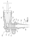
- FIG. 3 is a cross-sectional side view of an elbow connector having a stiff area and a soft area, according to an alternative exemplary embodiment.
- FIG. 1 is a cross-sectional side view of an elbow connector 100 having a stiff area 106 and a soft area 108 , according to an exemplary embodiment.
- the elbow connector 100 includes a shell 102 that includes a bushing entrance 110 having an opening 112 .
- a probe 114 is partially disposed within the opening 112 of the bushing entrance 110 .
- the opening 112 can be used to attach the elbow connector 100 to a switchgear, transformer, or other energy distribution component to which the elbow connector 100 may be connected.
- the probe 114 or other similar bushing may be inserted into the opening 112 , and then the probe 114 may be inserted into an energy distribution component.
- the shell 102 of the elbow connector 100 also can include a pulling eye 116 .
- the pulling eye 116 can function as a handle for the elbow connector 100 .
- the pulling eye 116 can be pulled or pushed to install the elbow connector 100 on an energy distribution component, to adjust the position of the elbow connector 100 , or to disconnect the elbow connector 100 from an energy distribution component.
- the elbow connector 100 also can include a semi-conductive insert 104 .
- the semi-conductive insert 104 can be disposed within the shell 102 , as shown in FIG. 1 .
- the semi-conductive insert 104 can include an upper section 124 that is disposed within the bushing entrance 110 of the shell 102 .
- the upper section 124 of the semi-conductive insert 104 can include an opening configured to accept a cable, plug, probe 114 , or another an energy distribution component inserted into the bushing entrance 110 of the shell 102 .
- the semi-conductive insert 104 can be made of the same material used in the manufacture of the shell 102 .
- the semi-conductive insert 104 can comprise EPDM rubber with carbon black mixed in, thereby providing the semi-conductive property for the semi-conductive insert 104 .
- the semi-conductive insert 104 , as well as the shell 102 can comprise any other type of suitable semi-conductive material known to those having ordinary skill in the art and having the benefit of the present disclosure. Examples of these materials include thermoplastic rubbers (TPRs) and silicone rubber.
- the elbow connector 100 also can comprise a variety of additional components and features.
- the elbow connector 100 can utilize a cable adapter.
- An exemplary cable adapter 216 is shown in FIG. 2 , shown inserted into an exemplary T-body connector 200 , which will be discussed in more detail with reference to FIG. 2 .
- a cable adapter 216 can be inserted into the semi-conductive insert 104 of the elbow connector to increase the variety of cables that can be used with the connector.
- an exemplary cable adapter 216 can include a semi-conductive section 236 and an insulating section 238 . Both sections 236 , 238 can comprise EPDM rubber, with the semi-conductive section 236 further including carbon black or other suitable conductive materials.
- each cable adapter 216 can be designed to accept a range of cable widths, each width within the range being sufficiently narrow to fit within the opening provided, and sufficiently wide to be secured within the cable adapter 216 .
- Each elbow connector 100 or in more specific exemplary embodiments, each semi-conductive insert 104 —then can be designed to accept a range of cable adapter 216 widths, thereby enabling each elbow connector to accept a large range of cable widths.
- the elbow connector 100 also can include a compression connector 128 .
- a compression connector 128 can be disposed within the semi-conductive insert 104 and can crimp a cable inserted into the elbow connector 100 , holding it in place, and allowing power to transfer from the cable to the elbow connector 100 .
- the top of the conductive compression connector 128 can contact—whether directly or indirectly—a cable, plug, probe 114 , or energy distribution component inserted into the bushing entrance 110 of the elbow connector 100 , as shown in FIG. 1 .
- the elbow connector 100 can include a capacitive test point 130 .
- the capacitive test point 130 can be molded on the shell 102 of the elbow connector 100 .
- the capacitive test point 130 can provide a location on which a fault indicating device, or other similar device, can be mounted to determine whether problems or irregularities exist with the electric power passing through the elbow connector 100 .
- a protective cap 132 can be placed on the capacitive test point 130 when it is not in use.
- the shell 102 of the elbow connector 100 also can include a ground wire tab 134 , to which a wire can be attached and grounded. Because the shell 102 can be made of semi-conductive EPDM rubber, the ground wire can provide ground shield continuity for the elbow connector 100 , thereby providing deadfront safety for the shell 102 . In other words, the grounded shell 102 can allow for operators to touch the exterior of the elbow connector 100 safely, thereby removing or reducing the risk of accidental electric shock.
- the shell 102 of the elbow connector 100 can include at least one soft area 108 and at least one stiff area 106 .
- such exemplary measurements include the tensile stress, elongation, modulus, and durometer of the materials.
- the modulus measurements which refer to the amount of pressure required to stretch (or elongate) the material a given percentage, can be taken at a variety of elongation percentages.
- the terms “soft” and “stiff” can refer to the relative hardness of two different materials.
- a soft material can comprise a material having between 1% and 15% lower tensile stress than a stiff material.
- a soft material can comprise a material having between 1% and 40% greater elongation than a stiff material and/or a material having between 5% and 25% lower durometer than a stiff material.
- a soft material can comprise a material having between 10% and 60% lower modulus at a variety of elongation percentages (i.e., at 50%, 75%, and 100% elongation) than a stiff material.
- the terms “soft” and “stiff” can refer to absolute values (as opposed to relative values) of exemplary hardness measurements.
- a soft area 108 can be located on or around the opening 112 of the bushing entrance 110 .
- Such a soft area 108 can provide increased flexibility and elasticity for the opening 112 of the bushing entrance 110 .
- the soft area 108 can allow for the insertion of a greater variety of cables, plugs, probes 114 , and/or energy distribution components into the opening of the shell 102 when compared to shells of conventional separable insulated connectors.
- the soft area 108 also can allow for easier installation and removal of the connector 100 to or from an energy distribution component.
- the shell 102 also can include a sleeve 109 surrounding the bushing entrance 110 .
- a sleeve 109 can be made from a relatively stiff material, and therefore can provide strength and sturdiness to the shell 102 .
- the soft area 108 can provide the desirable flexibility to allow insertion of a bushing
- the sleeve 109 can provide sturdiness to improve the tightness of the connection between the elbow connector 100 and the bushing inserted therein.
- the sleeve 109 also can provide many of the other advantages associated with stiff materials, such as enhanced durability and resistance to warping due to a power surge or fault current when compared to a soft material.
- the bushing entrance 110 may be less likely to “pop off” or get disconnected from the switchgear, transformer, or other energy distribution component to which the elbow connector 100 is connected. Without a sleeve 109 , a soft material—whether part of the shell 102 or insulating material 126 —located at or near the bushing entrance 110 may turn inside out during a fault close. A fault close can cause a blast or explosion, and if the elbow connector 100 or the bushing entrance 110 turns inside out, the forces of the explosion may be directed toward the operator, instead of away from the operator.
- the shell 102 of the elbow connector 100 also can include at least one stiff area 106 .
- the stiff area 106 can include the portion of the shell 102 that includes the angle 140 formed by the bending of the elbow connector 100 .
- the stiff area 106 can reduce or prevent the elbow connector 100 from straightening in the event of a power surge or lightening strike.
- stiff area 106 of the shell 102 also can include the pulling eye 116 .
- the stiff material in the pulling eye 116 can provide a strong, durable handle for installing, removing, or adjusting the elbow connector 100 , which is less likely to tear or shear compared to a softer material. Additionally, the stiff material can provide increased hoop stress in the pulling eye 116 , such that most of the force created from pulling on the pulling eye 116 can result in actually moving the pulling eye 116 . Conversely, if the pulling eye 116 is made of a softer, more flexible material, the pulling eye 116 may act as a shock absorber, thereby reducing the amount of force that will be applied to moving the pulling eye 116 and the elbow connector 100 .
- the stiff area 106 and the soft area 108 of the shell 102 can comprise a variety of materials.
- both the stiff area 106 and the soft area 108 can comprise EPDM rubber, another type of rubber, or any other suitable material known to those having ordinary skill in the art and having the benefit of the present disclosure.
- the shell 102 can comprise a mixture of EPDM rubber and conductive carbon black, thereby making the shell 102 semi-conductive.
- the relative stiffness or softness of the EPDM rubber can be controlled by adjusting the components mixed with the EPDM rubber. For example, increasing the amount of carbon black mixed with the EPDM rubber can increase the stiffness in the mixture. Conversely, mixing EPDM rubber with a lower amount of carbon black can make the mixture softer. Other factors beyond the amount of carbon black can affect the relative softness or stiffness of the mixture. Such factors are known to those having ordinary skill in the art and having the benefit of the present disclosure.
- FIG. 1 includes a dividing line, illustrating an exemplary border 118 between the soft area 108 and the stiff area 106 .
- the border 118 between the stiff and soft areas 106 , 108 can be at a variety of suitable locations along the shell 102 .
- the border 118 between the soft area 108 and stiff area 106 of the shell 102 can be chosen to provide the desired stiffness in the “pulling” section and the desired softness in the “connection” section.
- the soft area 108 and stiff area 106 of the shell 102 can form two separate sections that can be bonded together during the manufacturing process. In an exemplary embodiment, these two distinct sections can overlap at the joint between them.
- the soft area 108 can include an opening that is slightly wider than a corresponding opening in the stiff area 106 . In such an embodiment, a small portion of the stiff area 106 can be inserted into the soft area 108 .
- the soft area 108 and the stiff area 106 can be abutted with each other, or in other words, the soft area 108 can border the stiff area 106 without significant overlap between the two. In any of these exemplary embodiments, the materials of the stiff and soft areas 106 , 108 can be bonded together.
- the two sections can be joined together by a variety of methods.
- the soft area 108 and stiff area 106 can be formed separately, such as by using liquid EPDM rubber and separate steel mandrels or molds. The two sections then can be adjoined before they are completely cooled and hardened, thereby allowing the two sections to bond together while they cool.
- the separate soft area 108 and stiff area 106 sections can be joined after the two pieces have been cooled.
- the two sections can be held together by an adhesive or other bonding agent.
- insulating material 126 which will be discussed in more detail below, can be bond the two sections together upon cooling.
- the soft area 108 and stiff area 106 of the shell 102 may not form two separate sections. Rather, the shell 102 may include a single piece that includes both a soft area 108 and stiff area 106 .
- such a single-piece shell 102 can be formed by using a steel mandrel or mold that has two separate holes through which the soft material and stiff material can be injected. In such an embodiment, the two holes can be located on opposite sides of the steel mandrel or mold.
- the soft material can be injected through a hole on the side of the mold that can be used to form the portion of the shell 102 that contains the soft area 108
- the stiff material can be injected through a hole on the other side of the mold. After injection, the soft material and stiff material can meet and bond with each other within the mold, thereby forming a single-piece shell 102 comprising both a soft area 108 and a stiff area 106 .
- the semi-conductive insert 104 can include at least one soft area 122 and at least one stiff area 120 , as described previously with respect to the shell 102 .
- a soft area 122 can be located on the upper section 124 of the semi-conductive insert 104 that is disposed within the bushing entrance 110 of the shell 102 .
- the increased flexibility in the soft area 122 of the upper section 124 of the semi-conductive insert 104 can allow for the insertion of a greater variety of cables, plugs, probes, and/or energy distribution components into the semi-conductive insert 104 when compared to semi-conductive inserts of conventional separable insulated connectors.
- the semi-conductive insert 104 of the elbow connector 100 also can include at least one stiff area 120 .
- the stiff area 120 of the semi-conductive insert 104 can correspond with the portion of the semi-conductive insert 104 in which the cable adapter 216 can be inserted.
- the stiff area 120 also can include the portion of the semi-conductive insert 104 that corresponds with the pulling eye 116 of the shell 102 .
- the stiff area 120 can include the portion of the semi-conductive insert 104 that corresponds with the angle 140 of the elbow connector 100 .
- the stiff area 120 of the semi-conductive insert 104 can reduce or prevent any straightening of the elbow connector 100 in the event of a power surge or lightening strike.
- a semi-conductive insert 104 that includes at least one soft area 122 and at least one stiff area 120 can be manufactured by a variety of methods, as described previously with respect to the shell 102 .
- the soft area 122 and stiff area 120 of the semi-conductive insert 104 can form two separate sections that can be bonded together during the manufacturing process, which can utilize steel mandrels or molds.
- the separate sections can be abutted with each other, or there can be overlap between the two sections.
- the exemplary border 118 between the soft area 108 and the stiff area 106 of the shell 102 also can apply to the soft area 122 and stiff area 120 of the semi-conductive insert 104 .
- the border between the soft area 122 and stiff area 120 of the semi-conductive insert 104 may not be in line with the corresponding border 118 for the shell 102 .
- the border between the soft area 122 and stiff area 120 of the semi-conductive insert 104 can be chosen to provide the desired stiffness in the “pulling” section and the desired softness in the “connection” section.
- the separate soft area 122 and stiff area 120 sections can be joined after the two pieces have been cooled. In such an embodiment, the two sections can be held together by an adhesive or other bonding agent.
- the soft area 122 and stiff area 120 of the semi-conductive insert 104 may not form two separate sections. Rather, the semi-conductive insert 104 can comprise a single piece that includes both the soft area 122 and the stiff area 120 .
- Such a single-piece semi-conductive insert 104 can be formed by using a mold with two openings, and injecting the soft material into one opening, and the stiff material into the other opening with the soft and stiff materials meeting at the desired location of the joint 118 .
- manufacturing the separable insulated connector can include manufacturing the shell 102 , manufacturing the semi-conductive insert 104 , and then placing the semi-conductive insert 104 within the shell 102 .
- insulating material 126 can be injected into the shell 102 . Such insulating material 126 then can cool and bond to the shell 102 and to the semi-conductive insert 104 , thereby holding the semi-conductive insert 104 in place.
- the insulating material 126 also can bond the stiff areas 106 , 120 of the shell 102 and/or semi-conductive insert 104 to the corresponding soft areas 108 , 122 .
- the compression connector 128 then can be inserted into the semi-conductive insert 104 , and connected to a plug 214 or probe 114 that can be inserted into the bushing entrance 110 of the shell 102 .
- the insulating material 126 can comprise a variety of suitable materials, such as EPDM rubber, TPR, or silicone rubber. Unlike with the EPDM rubber that can be used to form the shell 102 and the semi-conductive insert 104 , the EPDM rubber forming the insulting material may not be mixed with carbon black. The absence of conductive carbon black can provide the insulating property for the EPDM rubber.
- the insulating material 126 also can comprise a stiff area and a soft area.
- the border between the stiff and soft areas of the insulating material 126 can roughly correspond with the 118 between the soft area 108 and stiff area 106 of the shell 102 .
- the border between the stiff and soft areas of the insulating material 126 can be placed in a different location from the border 118 between the soft area 108 and stiff area 106 of the shell 102 .
- the stiff and soft areas of the insulating material 126 can be formed using any of the methods described previously with respect to forming the stiff areas 106 , 120 and soft areas 108 , 122 of the shell 102 and/or semi-conductive insert 104 .
- the two areas of the insulating material 126 can be formed separately and then attached together, or the two areas can be formed by simultaneously injecting the two materials into opposite ends of a single mold.
- FIG. 2 is a cross-sectional side view of a T-body connector 200 having stiff areas 206 , 220 and a soft areas 208 , 222 for its shell 202 and semi-conductive insert 204 , according to an exemplary embodiment.
- the shape of the semi-conductive insert 204 and the shell 202 of the T-body connector 200 can be different from the shapes of the corresponding components of the elbow connector 100 , as shown in FIG. 1 .
- the bushing entrance 210 of the T-body connector 200 can include two openings: a first opening 212 and a second opening 213 .
- the first opening 212 can be used to attach the T-body connector 200 to an insert 214 , or other energy distribution component.
- the second opening 213 can be used to connect another device to the T-body connector 200 , such as a device for measuring the electric flow through the T-body connector 200 or to connect the T-body connector 200 to another energy distribution component.
- the second opening 213 of the T-body connector 200 need not be connected to another device, and a protective cap may cover the second opening 213 .
- the semi-conductive insert 204 of the T-body connector 200 can have a substantially straight shape, instead of bending in an elbow shape, as with the semi-conductive insert 104 of the elbow connector 100 .
- an exemplary T-body connector 200 can include many of the components and configurations discussed previously with respect to the elbow connector 100 .
- the shell 202 of the T-body connector 200 can include a pulling eye 116 .
- the pulling eye 116 can function as a handle for the T-body connector 100 .
- the T-body connector 200 also can include a semi-conductive insert 204 .
- the semi-conductive insert 204 can be disposed within the shell 202 , as shown in FIG. 2 .
- the semi-conductive insert 204 also can include an upper section 224 that is disposed within the bushing entrance 210 of the shell 202 .
- the upper section 224 of the semi-conductive insert 204 can include an opening configured to accept a cable, plug 214 , probe 114 , or another an energy distribution component inserted into the bushing entrance 210 of the shell 202 .
- the semi-conductive insert 204 of the T-body connector 200 can be made of the same material used in the manufacture of the shell 202 .
- the semi-conductive insert 204 can comprise EPDM rubber with carbon black mixed in, thereby providing the semi-conductive property for the semi-conductive insert 204 .
- a variety of other materials can be used to form the semi-conductive insert 204 or the shell 202 , as described previously with respect to the elbow connector 100 .
- the T-body connector 200 also can comprise a variety of additional components and features described previously with respect to the elbow connector 100 .
- the T-body connector 200 can utilize a cable adapter.
- An exemplary cable adapter 216 is shown in FIG. 2 , shown inserted into an exemplary T-body connector 200 , which will be discussed in more detail with reference to FIG. 2 .
- an exemplary cable adapter 216 can include a semi-conductive section 236 and an insulating section 238 . Both sections 236 , 238 can comprise EPDM rubber, with the semi-conductive section 236 further including carbon black or other suitable semi-conductive materials.
- each cable adapter 216 can be designed to accept a range of cable widths, each width within the range being sufficiently narrow to fit within the opening provided, and sufficiently wide to be secured within the cable adapter 216 .
- Each T-body connector 200 or in more specific exemplary embodiments, each semi-conductive insert 204 —then can be designed to accept a range of cable adapter 216 widths, thereby enabling each elbow connector to accept a large range of cable widths.
- the T-body connector 200 also can include a compression connector 128 that can be disposed within the semi-conductive insert 204 and can crimp a cable inserted into the T-body connector 200 .
- the T-body connector 200 can include a capacitive test point 130 molded on the shell 202 of the T-body connector 200 .
- a protective cap 132 can be placed on the capacitive test point 130 when it is not in use.
- the shell 202 of the T-body connector 200 also can include a ground wire tab 134 , to which a wire can be attached and grounded. As described previously with respect to the elbow connector 100 , use of the ground wire tab 134 can provide ground shield continuity for the T-body connector 200 , thereby providing deadfront safety for the shell 202 .
- the shell 202 and semi-conductive insert 204 of the T-body connector 200 can be made from a mixture comprising EPDM rubber and carbon black.
- the various exemplary methods and steps described previously for manufacturing the elbow connector 100 can largely be used for manufacturing a T-body connector 200 .
- either the shell 202 or the semi-conductive insert 204 of the T-body connector 200 can include a stiff area 206 , 220 and a soft area 208 , 222 , respectively.
- a soft area 208 can be located on the bushing entrance 210 —or particularly on the first opening 212 and/or second opening 213 of the bushing entrance 210 .
- Such a soft area 208 can provide increased flexibility and elasticity for the openings 212 , 213 of the bushing entrance 210 . This increased flexibility can allow for the easier insertion and removal of a greater variety of plugs, probes, and/or other energy distribution components into the openings of the shell 202 when compared to shells of conventional separable insulated connectors.
- a soft area 222 also can be located on the upper section 224 of the semi-conductive insert 204 , thereby providing additional flexibility.
- the soft areas 208 , 222 of the T-body connector 200 can be located towards the bottom of the shell 202 and/or semi-conductive insert 204 .
- the portion of the shell 202 and/or semi-conductive insert 204 in which the cable adapter 216 can be inserted can comprise the soft area 208 , 222 .
- Such a soft area 208 , 222 can provide increased flexibility and elasticity, thereby allowing a greater range of cable adapter 216 widths to be inserted therein, and be used with the T-body connector 200 .
- the stiff areas 206 , 220 of the T-body connector 200 can be located above the soft areas 208 , 222 , such as on the bushing entrance 210 .
- the T-body connector 200 may not include a stiff area 206 , 220 on the shell 202 and/or semi-conductive insert 204 .
- the shell 102 , 202 and/or semi-conductive insert 104 , 204 of the elbow connector 100 or T-body connector 200 can include additional stiff or soft areas, wherever extra strength or flexibility may be desirable.
- the bottom portion of the semi-conductive inserts 104 , 204 can comprise a soft area—whether in addition to or instead of a soft area 122 , 222 on the top portion of the semi-conductive insert 104 , 204 .
- Such a soft area can allow for more flexibility, thereby further increasing the variety of cable adapter 216 widths that can be used with the separable insulated connector and allowing easier installation and removal of the cable adapter 216 .
- a stiff bushing entrance 110 , 210 can create a tighter, more secure, and less flexible fit between the bushing entrance 110 , 210 and the bushing inserted therein. Such a tight fit can improve the dielectric performance of the connector 100 , 200 minimizing the amount of water or contaminants that could seep into the connector 100 , 200 .
- the tighter connection also can provide for fault closure between the connector 100 , 200 and the bushing or distribution component to which the connector 100 , 200 has been attached, thereby improving the safety of the installation, adjustment, and operation of the connector 100 , 200 .
- FIG. 3 is a cross-sectional side view of an elbow connector 300 having a stiff area 306 and a soft area 308 , according to an alternative exemplary embodiment.
- the elbow connector 300 is configured similarly to the elbow connector 100 shown in FIG. 1 , and includes many of the same components.
- the elbow connector 300 of FIG. 3 differs from the elbow connector 100 shown in FIG. 1 in that the stiff areas 306 , 320 and soft areas 308 , 322 of the shell 302 and semi-conductive insert 304 are positioned differently.
- the soft areas 308 , 322 of the elbow connector 300 can be located towards the bottom of the shell 302 and/or semi-conductive insert 304 .
- the portion of the shell 302 and/or semi-conductive insert 304 in which the cable can be inserted can comprise the soft area 308 , 322 .
- a soft area 308 , 322 can provide increased flexibility and elasticity, thereby allowing a greater range of cable widths to be inserted therein, and be used with the elbow connector 300 .
- the stiff areas 306 , 320 of the elbow connector 300 can be located above the soft areas 308 , 322 , as shown by the exemplary border 318 .
- the stiff areas 306 , 320 provide more strength in the area of the pulling eye 116 .
- the elbow connector 300 can include a cable adapter (not shown) that can function similarly to the cable adapter 216 disposed in the T-body connector 200 , and can include similar components.
- a cable adapter can include a semi-conductive section 336 and an insulating section 338 . Both sections 336 , 338 can comprise EPDM rubber or any other suitable type of rubber, with the semi-conductive section 336 further including carbon black or other suitable conductive materials.
Abstract
Description
Claims (13)
Priority Applications (1)
| Application Number | Priority Date | Filing Date | Title |
|---|---|---|---|
| US12/286,931 US8152547B2 (en) | 2008-02-27 | 2008-10-03 | Two-material separable insulated connector band |
Applications Claiming Priority (2)
| Application Number | Priority Date | Filing Date | Title |
|---|---|---|---|
| US12/072,647 US8109776B2 (en) | 2008-02-27 | 2008-02-27 | Two-material separable insulated connector |
| US12/286,931 US8152547B2 (en) | 2008-02-27 | 2008-10-03 | Two-material separable insulated connector band |
Related Parent Applications (1)
| Application Number | Title | Priority Date | Filing Date |
|---|---|---|---|
| US12/072,647 Continuation US8109776B2 (en) | 2008-02-27 | 2008-02-27 | Two-material separable insulated connector |
Publications (2)
| Publication Number | Publication Date |
|---|---|
| US20090215325A1 US20090215325A1 (en) | 2009-08-27 |
| US8152547B2 true US8152547B2 (en) | 2012-04-10 |
Family
ID=40998759
Family Applications (2)
| Application Number | Title | Priority Date | Filing Date |
|---|---|---|---|
| US12/072,647 Active 2028-04-29 US8109776B2 (en) | 2008-02-27 | 2008-02-27 | Two-material separable insulated connector |
| US12/286,931 Active US8152547B2 (en) | 2008-02-27 | 2008-10-03 | Two-material separable insulated connector band |
Family Applications Before (1)
| Application Number | Title | Priority Date | Filing Date |
|---|---|---|---|
| US12/072,647 Active 2028-04-29 US8109776B2 (en) | 2008-02-27 | 2008-02-27 | Two-material separable insulated connector |
Country Status (11)
| Country | Link |
|---|---|
| US (2) | US8109776B2 (en) |
| EP (2) | EP2258024B1 (en) |
| CN (1) | CN101999195B (en) |
| AU (1) | AU2009217496B2 (en) |
| BR (2) | BR122020023653B1 (en) |
| CA (1) | CA2716500C (en) |
| ES (1) | ES2652312T3 (en) |
| MX (1) | MX2010009288A (en) |
| PL (1) | PL2991167T3 (en) |
| TW (1) | TWI505571B (en) |
| WO (1) | WO2009108528A1 (en) |
Cited By (10)
| Publication number | Priority date | Publication date | Assignee | Title |
|---|---|---|---|---|
| US20110025342A1 (en) * | 2009-07-30 | 2011-02-03 | Thomas & Betts International, Inc. | Remote test point for electrical connector |
| US20120234795A1 (en) * | 2009-07-20 | 2012-09-20 | Abb Technology Ag | Method of manufacturing a current terminal for embedded pole part, and pole part itself |
| US20130005171A1 (en) * | 2010-05-17 | 2013-01-03 | Sumitomo Wiring Systems, Ltd. | Connector fixing structure |
| US20150004814A1 (en) * | 2012-02-14 | 2015-01-01 | Tyco Electronics Amp Gmbh | Housing having a seal |
| US20150295372A1 (en) * | 2014-04-10 | 2015-10-15 | S&C Electric Company | Adjustable bus bar for power distribution equipment |
| US9216530B2 (en) | 2012-10-08 | 2015-12-22 | Commscope Technologies Llc | Connector cover |
| US20160134065A1 (en) * | 2013-06-26 | 2016-05-12 | 3M Innovative Properties Company | Cable Connection Device |
| US9444176B2 (en) | 2013-06-28 | 2016-09-13 | Thomas & Betts International, Llc | Electrical connector having cold shrink component |
| US20170018915A1 (en) * | 2014-07-16 | 2017-01-19 | Richards Manufacturing Company Sales, Inc. | Secondary Transformer Bushing with Integral Sealing Legs |
| US9616602B2 (en) | 2013-07-10 | 2017-04-11 | Commscope Technologies Llc | Interconnection seal |
Families Citing this family (20)
| Publication number | Priority date | Publication date | Assignee | Title |
|---|---|---|---|---|
| US7905735B2 (en) | 2008-02-25 | 2011-03-15 | Cooper Technologies Company | Push-then-pull operation of a separable connector system |
| US7950940B2 (en) | 2008-02-25 | 2011-05-31 | Cooper Technologies Company | Separable connector with reduced surface contact |
| US8109776B2 (en) * | 2008-02-27 | 2012-02-07 | Cooper Technologies Company | Two-material separable insulated connector |
| CA2790987A1 (en) * | 2010-03-11 | 2011-09-15 | Electropar Limited | Improvements in electrical connectors and methods therefor |
| CN102386501B (en) * | 2010-09-04 | 2014-05-07 | 王日新 | Shielding type T-shaped capacitance type insulation bus joint |
| JP5883736B2 (en) * | 2012-07-13 | 2016-03-15 | 川崎重工業株式会社 | Main transformer and high-voltage equipment box connection structure and railcar equipped with the connection structure |
| CN102832528B (en) * | 2012-08-24 | 2016-03-30 | 深圳市沃尔核材股份有限公司 | A kind of production method of detachable shielded connector |
| US9401560B2 (en) * | 2013-07-30 | 2016-07-26 | Hubbell Incorporated (Delaware) | High power single-pole electrical connector |
| CN104953333B (en) * | 2014-03-26 | 2017-07-28 | 富士康(昆山)电脑接插件有限公司 | Micro coaxial cable connector assembly and its manufacture method |
| JP1541105S (en) * | 2014-12-12 | 2016-01-12 | ||
| CN104901061A (en) * | 2015-02-13 | 2015-09-09 | 深圳巴斯巴科技发展有限公司 | Novel soft-connection high-voltage connector |
| US9941616B2 (en) * | 2015-02-24 | 2018-04-10 | Thomas & Betts International Llc | Multi-piece jacket for separable connectors |
| CN105529562B (en) * | 2016-01-19 | 2018-09-28 | 孙萍 | Elbow single-core cable connector |
| US10971842B2 (en) * | 2018-06-27 | 2021-04-06 | Abb Schweiz Ag | Loadbreak electrical connector with enhanced safety probe |
| CN108923140B (en) * | 2018-07-11 | 2020-03-27 | 云南电网有限责任公司电力科学研究院 | Cable elbow type head shielding grounding device and installation method |
| CN109861011A (en) * | 2018-08-30 | 2019-06-07 | 广州亿威科技有限责任公司 | Connect the connector of aluminum steel |
| JP7313185B2 (en) * | 2019-04-30 | 2023-07-24 | タイコエレクトロニクスジャパン合同会社 | connector housing |
| TWM588385U (en) * | 2019-07-08 | 2019-12-21 | 台灣翔登股份有限公司 | Cable connector |
| KR20220071968A (en) * | 2019-10-18 | 2022-05-31 | 타이코 일렉트로닉스 저팬 지.케이. | connector housing |
| CA3170977A1 (en) | 2020-02-13 | 2021-08-19 | Hubbell Incorporated | Tee arrester with directional venting |
Citations (262)
| Publication number | Priority date | Publication date | Assignee | Title |
|---|---|---|---|---|
| GB105227A (en) | 1916-03-31 | 1918-02-14 | Henri De La Valette | Improvements in Electric Couplings. |
| US1903956A (en) | 1931-04-17 | 1933-04-18 | Reyrolle A & Co Ltd | High voltage electric switch gear |
| US2953724A (en) | 1954-05-11 | 1960-09-20 | Hilfiker Hans | Electrical distribution boards |
| US3115329A (en) | 1959-10-14 | 1963-12-24 | Wilson G Wing | Valve |
| US3315132A (en) | 1964-10-09 | 1967-04-18 | Johnson & Phillips Australia P | Busbar power distribution systems |
| US3392363A (en) | 1965-06-10 | 1968-07-09 | Amp Inc | Housing member for electrical connector members |
| US3471669A (en) | 1968-01-16 | 1969-10-07 | Chance Co Ab | Encapsulated switch assembly for underground electric distribution service |
| US3474386A (en) | 1964-02-10 | 1969-10-21 | Edwin A Link | Electrical connector |
| US3509518A (en) | 1968-03-11 | 1970-04-28 | Mc Graw Edison Co | High voltage cable connectors |
| US3509516A (en) | 1968-02-01 | 1970-04-28 | Mc Graw Edison Co | High voltage connector and entrance bushing assembly |
| US3513425A (en) | 1969-05-21 | 1970-05-19 | Gen Electric | Modular electrical conductor termination system |
| US3539972A (en) | 1968-05-21 | 1970-11-10 | Amerace Esna Corp | Electrical connector for high voltage electrical systems |
| US3542986A (en) | 1968-02-23 | 1970-11-24 | Gen Electric | Quick-make,quick-break actuator for high voltage electrical contacts |
| US3546535A (en) | 1967-10-10 | 1970-12-08 | Smit Nijmegen Electrotec | Transformers and composite tap changers associated therewith |
| US3576493A (en) | 1969-09-25 | 1971-04-27 | Gen Electric | Molded conductor housing with a molded capacitance tap and method of making same |
| US3594685A (en) | 1969-07-14 | 1971-07-20 | Joslyn Mfg & Supply Co | Electrical coupler |
| US3652975A (en) | 1970-01-09 | 1972-03-28 | Westinghouse Electric Corp | Electrical connector assembly |
| US3654590A (en) | 1969-12-30 | 1972-04-04 | Ameraca Esna Corp | Electrical contact devices for high voltage electrical systems |
| US3663928A (en) | 1970-01-09 | 1972-05-16 | Westinghouse Electric Corp | Electrical bushing assembly |
| US3670287A (en) | 1970-08-17 | 1972-06-13 | Westinghouse Electric Corp | Electrical connector assembly |
| US3678432A (en) * | 1971-04-26 | 1972-07-18 | Gen Electric | Vented fuse module for underground power cable system |
| US3711818A (en) * | 1970-11-09 | 1973-01-16 | Joslyn Mfg & Supply Co | Electrical disconnect |
| US3720904A (en) | 1971-02-04 | 1973-03-13 | Amp Inc | Self-actuating loadbreak connector |
| US3725846A (en) * | 1970-10-30 | 1973-04-03 | Itt | Waterproof high voltage connection apparatus |
| US3740503A (en) | 1972-05-02 | 1973-06-19 | Omron Tateisi Electronics Co | Conducting fluid inertia type switch with linearly movable conductive plunger contact |
| US3740511A (en) | 1971-05-06 | 1973-06-19 | J Westmoreland | Vacuum switch |
| US3798586A (en) | 1972-05-22 | 1974-03-19 | P Huska | Union for connecting electrical conductors |
| US3826860A (en) | 1973-03-08 | 1974-07-30 | Amp Inc | High voltage electrical connector |
| US3845233A (en) | 1973-02-12 | 1974-10-29 | Dielectrics Int Ltd | Pressurized insulant of solid and fluid for a conductor |
| US3860322A (en) | 1972-01-03 | 1975-01-14 | Rte Corp | Sealed electrical connector |
| US3915534A (en) | 1967-08-15 | 1975-10-28 | Joslyn Mfg & Supply Co | Grounded surface distribution apparatus |
| US3924914A (en) | 1970-03-04 | 1975-12-09 | Philip M Banner | Electrical safety grounding device means |
| US3945699A (en) | 1974-09-27 | 1976-03-23 | Kearney-National Inc. | Electric connector apparatus and method |
| US3949343A (en) | 1967-08-15 | 1976-04-06 | Joslyn Mfg. And Supply Co. | Grounded surface distribution apparatus |
| US3953099A (en) | 1973-12-10 | 1976-04-27 | Bunker Ramo Corporation | One-piece environmental removable contact connector |
| US3955874A (en) | 1974-10-29 | 1976-05-11 | General Electric Company | Shielded power cable separable connector module having a conductively coated insulating rod follower |
| US3957332A (en) | 1975-05-02 | 1976-05-18 | Kearney-National, Inc. | Electric connector apparatus and method |
| US3960433A (en) | 1975-09-05 | 1976-06-01 | General Electric Company | Shielded power cable separable connector module having conducting contact rod with a beveled shoulder overlapped by insulating follower material |
| US4029380A (en) | 1967-08-15 | 1977-06-14 | Joslyn Mfg. And Supply Co. | Grounded surface distribution apparatus |
| US4040696A (en) | 1975-04-30 | 1977-08-09 | Matsushita Electric Works, Ltd. | Electric device having rotary current collecting means |
| US4067636A (en) | 1976-08-20 | 1978-01-10 | General Electric Company | Electrical separable connector with stress-graded interface |
| US4088383A (en) | 1976-08-16 | 1978-05-09 | International Telephone And Telegraph Corporation | Fault-closable electrical connector |
| US4102608A (en) | 1975-12-24 | 1978-07-25 | Commonwealth Scientific And Industrial Research Organization | Reciprocatory piston and cylinder machines |
| US4103123A (en) | 1977-06-27 | 1978-07-25 | Northwestern Public Service Company | Grounding device |
| US4107486A (en) | 1976-06-30 | 1978-08-15 | S & C Electric Company | Switch operating mechanisms for high voltage switches |
| US4113339A (en) | 1977-08-29 | 1978-09-12 | Westinghouse Electric Corp. | Load break bushing |
| US4123131A (en) | 1977-08-05 | 1978-10-31 | General Motors Corporation | Vented electrical connector |
| US4152643A (en) | 1978-04-10 | 1979-05-01 | E. O. Schweitzer Manufacturing Co., Inc. | Voltage indicating test point cap |
| US4154993A (en) | 1977-09-26 | 1979-05-15 | Mcgraw-Edison Company | Cable connected drawout switchgear |
| US4161012A (en) | 1977-03-02 | 1979-07-10 | Joslyn Mfg. And Supply Co. | High voltage protection apparatus |
| US4163118A (en) | 1977-04-19 | 1979-07-31 | Coq B.V. | Busbar system of electric high-voltage switchgear |
| US4186985A (en) | 1978-08-29 | 1980-02-05 | Amerace Corporation | Electrical connector |
| US4203017A (en) | 1978-07-24 | 1980-05-13 | Integrated Electronics Corporation | Electric switch |
| US4210381A (en) | 1978-08-30 | 1980-07-01 | Amerace Corporation | Electrical connector contacts |
| US4223179A (en) | 1978-01-05 | 1980-09-16 | Joslyn Mfg. And Supply Co. | Cable termination connector assembly |
| US4260214A (en) | 1979-07-23 | 1981-04-07 | International Telephone And Telegraph Corporation | Fault-closable electrical connector |
| US4343356A (en) | 1972-10-06 | 1982-08-10 | Sonics International, Inc. | Method and apparatus for treating subsurface boreholes |
| DE3110609A1 (en) | 1981-03-18 | 1982-10-07 | Siemens Ag | Mechanical-electrical plug connection |
| US4353611A (en) | 1980-03-06 | 1982-10-12 | Amerace Corporation | Bushing well stud construction |
| US4354721A (en) | 1980-12-31 | 1982-10-19 | Amerace Corporation | Attachment arrangement for high voltage electrical connector |
| US4360967A (en) | 1980-12-31 | 1982-11-30 | Amerace Corporation | Assembly tool for electrical connectors |
| FR2508729A1 (en) | 1981-06-24 | 1982-12-31 | Lb Air | Enclosed cylindrical electrical connector for single bare-ended wires - has mating tubular sections with device for releasing radial holding force during disconnection |
| US4443054A (en) | 1981-06-01 | 1984-04-17 | Kanagawa Prefectual Government | Earth terminal for electrical equipment |
| US4463227A (en) | 1982-02-05 | 1984-07-31 | S&C Electric Company | Mounting for an article which permits movement thereof between inaccessible and accessible positions |
| US4484169A (en) | 1981-11-05 | 1984-11-20 | Mitsubishi Denki Kabushiki Kaisha | Transformer apparatus with -superimposed insulated switch and transformer units |
| US4500935A (en) | 1981-09-02 | 1985-02-19 | Mitsubishi Denki Kabushiki Kaisha | Package substation in tank with separate chambers |
| US4508413A (en) | 1982-04-12 | 1985-04-02 | Allied Corporation | Connector |
| US4568804A (en) | 1983-09-06 | 1986-02-04 | Joslyn Mfg. And Supply Co. | High voltage vacuum type circuit interrupter |
| US4600260A (en) | 1981-12-28 | 1986-07-15 | Amerace Corporation | Electrical connector |
| US4626755A (en) | 1984-12-14 | 1986-12-02 | General Electric Company | Sump pump motor switch circuit |
| US4638403A (en) | 1983-06-15 | 1987-01-20 | Hitachi, Ltd. | Gas-insulated switchgear apparatus |
| DE3521365C1 (en) | 1985-06-14 | 1987-02-19 | Stocko Metallwarenfab Henkels | Electrical plug connection |
| US4678253A (en) | 1984-10-29 | 1987-07-07 | Eaton Corporation | Bus duct having improved bus bar clamping structure |
| US4688013A (en) | 1985-05-09 | 1987-08-18 | Mitsubishi Denki Kabushiki Kaisha | Switchgear assembly for electrical apparatus |
| US4700258A (en) | 1986-07-21 | 1987-10-13 | Colt Industries Inc. | Lightning arrester system for underground loop distribution circuit |
| JPS62198677U (en) | 1986-06-09 | 1987-12-17 | ||
| US4714438A (en) * | 1985-07-19 | 1987-12-22 | Bicc Public Limited Company | Electric cable joints |
| US4715104A (en) | 1986-09-18 | 1987-12-29 | Rte Corporation | Installation tool |
| US4722694A (en) | 1986-12-01 | 1988-02-02 | Rte Corporation | High voltage cable connector |
| JPS6393081U (en) | 1986-12-05 | 1988-06-16 | ||
| US4767941A (en) | 1985-11-14 | 1988-08-30 | Bbc Brown, Boveri & Co., Ltd. | Method for error-protected actuation of the switching devices of a switching station and an apparatus thereof |
| US4767894A (en) | 1984-12-22 | 1988-08-30 | Bp Chemicals Limited | Laminated insulated cable having strippable layers |
| US4779341A (en) | 1987-10-13 | 1988-10-25 | Rte Corporation | Method of using a tap plug installation tool |
| US4793637A (en) | 1987-09-14 | 1988-12-27 | Aeroquip Corporation | Tube connector with indicator and release |
| US4799895A (en) | 1987-06-22 | 1989-01-24 | Amerace Corporation | 600-Amp hot stick operable screw-assembled connector system |
| US4820183A (en) | 1986-09-12 | 1989-04-11 | Cooper Industries | Connection mechanism for connecting a cable connector to a bushing |
| US4822951A (en) | 1987-11-30 | 1989-04-18 | Westinghouse Canada Inc. | Busbar arrangement for a switchgear assembly |
| US4822291A (en) | 1986-03-20 | 1989-04-18 | Joslyn Corporation | Gas operated electrical connector |
| US4834677A (en) | 1987-04-10 | 1989-05-30 | Baxter Travenol Laboratories, Inc. | Male and/or female electrical connectors |
| US4857021A (en) | 1988-10-17 | 1989-08-15 | Cooper Power Systems, Inc. | Electrical connector assembly and method for connecting the same |
| US4863392A (en) | 1988-10-07 | 1989-09-05 | Amerace Corporation | High-voltage loadbreak bushing insert connector |
| US4867687A (en) | 1988-06-29 | 1989-09-19 | Houston Industries Incorporated | Electrical elbow connection |
| US4871888A (en) | 1988-02-16 | 1989-10-03 | Bestel Ernest F | Tubular supported axial magnetic field interrupter |
| US4875581A (en) * | 1985-03-19 | 1989-10-24 | Robert B. Ray | Static dissipative elastomeric coating for electronic packaging components |
| US4891016A (en) | 1989-03-29 | 1990-01-02 | Amerace Corporation | 600-Amp hot stick-operable pin-and-socket assembled connector system |
| US4911655A (en) | 1988-09-19 | 1990-03-27 | Raychem Corporation | Wire connect and disconnect indicator |
| US4946393A (en) | 1989-08-04 | 1990-08-07 | Amerace Corporation | Separable connector access port and fittings |
| US4955823A (en) | 1989-10-10 | 1990-09-11 | Amerace Corporation | 600-Amp hot stick-operable screw and pin-and-socket assembled connector system |
| US4972049A (en) | 1987-12-11 | 1990-11-20 | Cooper Power Systems, Inc. | Bushing and gasket assembly |
| US4982059A (en) | 1990-01-02 | 1991-01-01 | Cooper Industries, Inc. | Axial magnetic field interrupter |
| US5025121A (en) | 1988-12-19 | 1991-06-18 | Siemens Energy & Automation, Inc. | Circuit breaker contact assembly |
| US5045968A (en) | 1988-03-11 | 1991-09-03 | Hitachi, Ltd. | Gas insulated switchgear with bus-section-unit circuit breaker and disconnect switches connected to external lead-out means connectable to other gas insulated switchgear |
| US5045656A (en) | 1989-07-05 | 1991-09-03 | Idec Izumi Corporation | Switch provided with indicator |
| US5053584A (en) | 1990-07-25 | 1991-10-01 | Controlled Power Limited Partnership | Adjustable support assembly for electrical conductors |
| US5101080A (en) | 1988-06-09 | 1992-03-31 | Klockner-Moeller Elektrizitats-Gmbh | Busbar for current distributor rails, switchgear and the like |
| US5114357A (en) * | 1991-04-29 | 1992-05-19 | Amerace Corporation | High voltage elbow |
| US5128824A (en) | 1991-02-20 | 1992-07-07 | Amerace Corporation | Directionally vented underground distribution surge arrester |
| US5130495A (en) | 1991-01-24 | 1992-07-14 | G & W Electric Company | Cable terminator |
| US5132495A (en) | 1991-01-23 | 1992-07-21 | Homac Mfg. Company | Submersible splice cover with resilient corrugated and sections |
| GB2254493A (en) | 1990-12-27 | 1992-10-07 | Rover Group | A connector for a high tension lead. |
| US5166861A (en) | 1991-07-18 | 1992-11-24 | Square D Company | Circuit breaker switchboard |
| US5175403A (en) | 1991-08-22 | 1992-12-29 | Cooper Power Systems, Inc. | Recloser means for reclosing interrupted high voltage electric circuit means |
| US5213517A (en) | 1992-02-10 | 1993-05-25 | G & H Technology, Inc. | Separable electrodes with electric arc quenching means |
| US5215475A (en) * | 1992-07-02 | 1993-06-01 | Amerace Corporation | Devices for use with high voltage system components for the safe expulsion of conductive moisture within such components |
| US5221220A (en) | 1992-04-09 | 1993-06-22 | Cooper Power Systems, Inc. | Standoff bushing assembly |
| US5230142A (en) | 1992-03-20 | 1993-07-27 | Cooper Power Systems, Inc. | Operating and torque tool |
| US5230640A (en) | 1991-03-12 | 1993-07-27 | Cables Pirelli | Connecting device for one or two electric cables, and process for mounting this device on the end of the cable or cables |
| US5248263A (en) | 1990-11-22 | 1993-09-28 | Yazaki Corporation | Watertight electric connector |
| US5266041A (en) | 1992-01-24 | 1993-11-30 | Luca Carlo B De | Loadswitching bushing connector for high power electrical systems |
| US5277605A (en) | 1992-09-10 | 1994-01-11 | Cooper Power Systems, Inc. | Electrical connector |
| US5356304A (en) | 1993-09-27 | 1994-10-18 | Molex Incorporated | Sealed connector |
| US5359163A (en) | 1993-04-28 | 1994-10-25 | Eaton Corporation | Pushbutton switch with adjustable pretravel |
| US5358420A (en) | 1993-06-07 | 1994-10-25 | Ford Motor Company | Pressure relief for an electrical connector |
| US5393240A (en) | 1993-05-28 | 1995-02-28 | Cooper Industries, Inc. | Separable loadbreak connector |
| US5422440A (en) | 1993-06-08 | 1995-06-06 | Rem Technologies, Inc. | Low inductance bus bar arrangement for high power inverters |
| US5427538A (en) | 1993-09-22 | 1995-06-27 | Cooper Industries, Inc. | Electrical connecting system |
| US5429519A (en) | 1992-09-03 | 1995-07-04 | Sumitomo Wiring Systems, Ltd. | Connector examining device |
| US5433622A (en) | 1994-07-07 | 1995-07-18 | Galambos; Louis G. | High voltage connector |
| US5435747A (en) | 1991-02-25 | 1995-07-25 | N.V. Raychem S.A. | Electrically-protected connector |
| US5468164A (en) | 1993-08-20 | 1995-11-21 | Gec Alsthom T & D, Inc. | Female contact, in particular for a high tension section switch |
| US5492487A (en) | 1993-06-07 | 1996-02-20 | Ford Motor Company | Seal retention for an electrical connector assembly |
| US5589671A (en) | 1995-08-22 | 1996-12-31 | Us Controls Corp. | Rotary switch with spring stabilized contact control rotor |
| EP0624940B1 (en) | 1993-05-14 | 1997-03-26 | Legrand | Trunking with a cover joint device equipped with a fastener, especially for electrical apparatus |
| US5619021A (en) | 1993-11-19 | 1997-04-08 | Sumitomo Wiring Systems, Ltd. | Lever switch device, method for activating switches in a lever switch device, and method for outputting data signals |
| US5641310A (en) | 1994-12-08 | 1997-06-24 | Hubbell Incorporated | Locking type electrical connector with retention feature |
| EP0782162A2 (en) | 1995-12-26 | 1997-07-02 | Amerace Corporation | High voltage switches |
| US5655921A (en) | 1995-06-07 | 1997-08-12 | Cooper Industries, Inc. | Loadbreak separable connector |
| US5661280A (en) | 1995-08-02 | 1997-08-26 | Abb Power T&D Company Inc. | Combination of a gas-filled interrupter and oil-filled transformer |
| US5667060A (en) | 1995-12-26 | 1997-09-16 | Amerace Corporation | Diaphragm seal for a high voltage switch environment |
| US5676901A (en) | 1992-06-19 | 1997-10-14 | Matsushita Electric Works, Ltd. | Process for resin-coating of resin moldings, resin-coating apparatus for use in the process |
| US5717185A (en) | 1995-12-26 | 1998-02-10 | Amerace Corporation | Operating mechanism for high voltage switch |
| US5736705A (en) | 1996-09-13 | 1998-04-07 | Cooper Industries, Inc. | Grading ring insert assembly |
| US5737874A (en) | 1994-12-15 | 1998-04-14 | Simon Roofing And Sheet Metal Corp. | Shutter construction and method of assembly |
| US5747765A (en) | 1996-09-13 | 1998-05-05 | Cooper Industries, Inc. | Vertical antitracking skirts |
| US5747766A (en) | 1993-03-16 | 1998-05-05 | Cooper Industries, Inc. | Operating mechanism usable with a vacuum interrupter |
| US5757260A (en) | 1996-09-26 | 1998-05-26 | Eaton Corporation | Medium voltage switchgear with means for changing fuses |
| US5766030A (en) | 1995-12-25 | 1998-06-16 | Yazaki Corporation | Cap type connector assembly for high-voltage cable |
| US5766517A (en) | 1995-12-21 | 1998-06-16 | Cooper Industries, Inc. | Dielectric fluid for use in power distribution equipment |
| US5795180A (en) | 1996-12-04 | 1998-08-18 | Amerace Corporation | Elbow seating indicator |
| US5799986A (en) | 1994-12-21 | 1998-09-01 | Flex Technologies, Inc. | Connector assembly and method of manufacture |
| US5816835A (en) | 1996-10-21 | 1998-10-06 | Alden Products Company | Multi-sleeve high-voltage cable plug with vented seal |
| US5846093A (en) | 1997-05-21 | 1998-12-08 | Cooper Industries, Inc. | Separable connector with a reinforcing member |
| US5857862A (en) | 1997-03-04 | 1999-01-12 | Cooper Industries, Inc. | Loadbreak separable connector |
| JPH1175181A (en) | 1998-07-07 | 1999-03-16 | Sony Corp | Converter and conversion method for digital image signal |
| US5886294A (en) | 1995-05-30 | 1999-03-23 | Scrimpshire; James Michael | Interference suppressing cable boot assembly |
| US5912604A (en) | 1997-02-04 | 1999-06-15 | Abb Power T&D Company, Inc. | Molded pole automatic circuit recloser with bistable electromagnetic actuator |
| US5917167A (en) | 1996-09-13 | 1999-06-29 | Cooper Industries, Inc. | Encapsulated vacuum interrupter and method of making same |
| US5936825A (en) | 1998-03-18 | 1999-08-10 | Copper Industries, Inc. | Rise pole termination/arrestor combination |
| US5949641A (en) | 1998-11-09 | 1999-09-07 | Eaton Corporation | Mounting arrangement for neutral bus in switchgear assembly |
| US5953193A (en) | 1994-12-20 | 1999-09-14 | A.C. Data Systems, Inc. | Power surge protection assembly |
| US5957712A (en) | 1997-07-30 | 1999-09-28 | Thomas & Betts International, Inc. | Loadbreak connector assembly which prevents switching flashover |
| EP0957496A2 (en) | 1998-05-11 | 1999-11-17 | ABB Trasformatori S.p.A. | Power and/or distribution transformer equipped with on-load tap-changer |
| US6022247A (en) | 1996-12-10 | 2000-02-08 | Yazaki Corporation | Electric wiring block |
| US6040538A (en) | 1996-05-24 | 2000-03-21 | S&C Electric Company | Switchgear assembly |
| US6042407A (en) | 1998-04-23 | 2000-03-28 | Hubbell Incorporated | Safe-operating load reducing tap plug and method using the same |
| US6069321A (en) | 1997-03-12 | 2000-05-30 | Rittal-Werk Rudolf Loh Gmbh & Co. Kg | Device for attaching busbar to a support rail |
| US6071130A (en) | 1998-11-30 | 2000-06-06 | 3Com Corporation | Surface mounted contact block |
| WO2000041199A1 (en) | 1999-01-06 | 2000-07-13 | Nu-Lec Industries Pty Ltd | Method for assembly of insulated housings for electrical equipment and incorporation of circuit interrupters therein |
| US6103975A (en) * | 1998-06-29 | 2000-08-15 | 3M Innovative Properties Company | Pre-assembled electrical splice component |
| DE19906972A1 (en) | 1999-02-19 | 2000-08-24 | Abb Patent Gmbh | Vacuum switch chamber has cylindrical insulating ring between housing and vacuum chamber and compressed so elastic material is pressed against internal housing and external chamber surfaces |
| US6116963A (en) | 1998-10-09 | 2000-09-12 | Pulse Engineering, Inc. | Two-piece microelectronic connector and method |
| US6130394A (en) | 1996-08-26 | 2000-10-10 | Elektrotechnische Weke Fritz Driescher & Sohne GmbH | Hermetically sealed vacuum load interrupter switch with flashover features |
| US6168447B1 (en) | 1997-07-30 | 2001-01-02 | Thomas & Betts International, Inc. | Loadbreak connector assembly which prevents switching flashover |
| US6179639B1 (en) * | 1998-07-16 | 2001-01-30 | Sumitomo Wiring Systems, Ltd. | Electrical connector with a resiliently expansible locking element |
| US6205029B1 (en) | 1996-11-15 | 2001-03-20 | Lucent Technologies Inc. | Modular power supply chassis employing a bus bar assembly |
| US6213799B1 (en) * | 1998-05-27 | 2001-04-10 | Hubbell Incorporated | Anti-flashover ring for a bushing insert |
| US6220888B1 (en) | 1999-06-25 | 2001-04-24 | Hubbell Incorporated | Quick disconnect cable connector device with integral body and strain relief structure |
| US6227908B1 (en) | 1996-07-26 | 2001-05-08 | Wolfram Aumeier | Electric connection |
| US6250950B1 (en) | 1998-11-25 | 2001-06-26 | Supplie & Co. Import/Export, Inc. | Screwless terminal block |
| US6280659B1 (en) | 1996-03-01 | 2001-08-28 | David W. Sundin | Vegetable seed oil insulating fluid |
| US6305563B1 (en) | 1999-01-12 | 2001-10-23 | Aptargroup, Inc, | One-piece dispensing structure and method and apparatus for making same |
| US6332785B1 (en) | 1997-06-30 | 2001-12-25 | Cooper Industries, Inc. | High voltage electrical connector with access cavity and inserts for use therewith |
| US6362445B1 (en) | 2000-01-03 | 2002-03-26 | Eaton Corporation | Modular, miniaturized switchgear |
| US6364216B1 (en) | 2001-02-20 | 2002-04-02 | G&W Electric Co. | Universal power connector for joining flexible cables to rigid devices in any of many configurations |
| US6416338B1 (en) | 2001-03-13 | 2002-07-09 | Hubbell Incorporated | Electrical connector with dual action piston |
| US6429373B1 (en) | 2000-02-20 | 2002-08-06 | James M. Scrimpshire | Multipurpose flexible cable boot for enclosing trunk and feeder cable connectors |
| US6453776B1 (en) | 2001-03-14 | 2002-09-24 | Saskatchewan Power Corporation | Separable loadbreak connector flashover inhibiting cuff venting tool |
| US6478584B2 (en) | 1999-05-25 | 2002-11-12 | Transense Technologies Plc | Electrical signal coupling device |
| US6504103B1 (en) | 1993-03-19 | 2003-01-07 | Cooper Industries, Inc. | Visual latching indicator arrangement for an electrical bushing and terminator |
| US6517366B2 (en) | 2000-12-06 | 2003-02-11 | Utilx Corporation | Method and apparatus for blocking pathways between a power cable and the environment |
| US6520795B1 (en) | 2001-08-02 | 2003-02-18 | Hubbell Incorporated | Load reducing electrical device |
| US6538312B1 (en) | 2000-05-16 | 2003-03-25 | Sandia Corporation | Multilayered microelectronic device package with an integral window |
| US6542056B2 (en) | 2001-04-30 | 2003-04-01 | Eaton Corporation | Circuit breaker having a movable and illuminable arc fault indicator |
| US6566996B1 (en) | 1999-09-24 | 2003-05-20 | Cooper Technologies | Fuse state indicator |
| US6664478B2 (en) | 2000-02-12 | 2003-12-16 | Tyco Electronics Uk Ltd. | Bus bar assembly |
| US6689947B2 (en) | 1998-05-15 | 2004-02-10 | Lester Frank Ludwig | Real-time floor controller for control of music, signal processing, mixing, video, lighting, and other systems |
| US6705898B2 (en) | 2000-11-07 | 2004-03-16 | Endress + Hauser Conducta Gesellschaft Fur Mess-Und Regeltechnik Mbh +Co. | Connector for connecting a transmission line to at least one sensor |
| US6709294B1 (en) | 2002-12-17 | 2004-03-23 | Teradyne, Inc. | Electrical connector with conductive plastic features |
| US6733322B2 (en) | 2000-09-01 | 2004-05-11 | Tyco Electronics Amp Gmbh | Pluggable connection housing with anti-kink element |
| US6744255B1 (en) | 2002-10-30 | 2004-06-01 | Mcgraw -Edison Company | Grounding device for electric power distribution systems |
| US6790063B2 (en) | 2002-05-16 | 2004-09-14 | Homac Mfg. Company | Electrical connector including split shield monitor point and associated methods |
| US6796820B2 (en) | 2002-05-16 | 2004-09-28 | Homac Mfg. Company | Electrical connector including cold shrink core and thermoplastic elastomer material and associated methods |
| US6809413B1 (en) | 2000-05-16 | 2004-10-26 | Sandia Corporation | Microelectronic device package with an integral window mounted in a recessed lip |
| US6811418B2 (en) | 2002-05-16 | 2004-11-02 | Homac Mfg. Company | Electrical connector with anti-flashover configuration and associated methods |
| US6830475B2 (en) | 2002-05-16 | 2004-12-14 | Homac Mfg. Company | Electrical connector with visual seating indicator and associated methods |
| US6843685B1 (en) | 2003-12-24 | 2005-01-18 | Thomas & Betts International, Inc. | Electrical connector with voltage detection point insulation shield |
| US6888086B2 (en) | 2002-09-30 | 2005-05-03 | Cooper Technologies Company | Solid dielectric encapsulated interrupter |
| US6905356B2 (en) | 2002-05-16 | 2005-06-14 | Homac Mfg. Company | Electrical connector including thermoplastic elastomer material and associated methods |
| US6936947B1 (en) | 1996-05-29 | 2005-08-30 | Abb Ab | Turbo generator plant with a high voltage electric generator |
| US6939151B2 (en) | 1997-07-30 | 2005-09-06 | Thomas & Betts International, Inc. | Loadbreak connector assembly which prevents switching flashover |
| US6972378B2 (en) | 2002-06-16 | 2005-12-06 | Maclean-Fogg Company | Composite insulator |
| US6984791B1 (en) | 1993-03-19 | 2006-01-10 | Cooper Technologies Company | Visual latching indicator arrangement for an electrical bushing and terminator |
| US7019606B2 (en) | 2004-03-29 | 2006-03-28 | General Electric Company | Circuit breaker configured to be remotely operated |
| US7018236B2 (en) | 2003-11-21 | 2006-03-28 | Mitsumi Electric Co., Ltd. | Connector with resin molded portion |
| US7044760B2 (en) | 1997-07-30 | 2006-05-16 | Thomas & Betts International, Inc. | Separable electrical connector assembly |
| US7044769B2 (en) | 2003-11-26 | 2006-05-16 | Hubbell Incorporated | Electrical connector with seating indicator |
| US7050278B2 (en) | 2002-05-22 | 2006-05-23 | Danfoss Drives A/S | Motor controller incorporating an electronic circuit for protection against inrush currents |
| US7059879B2 (en) | 2004-05-20 | 2006-06-13 | Hubbell Incorporated | Electrical connector having a piston-contact element |
| US7079367B1 (en) | 1999-11-04 | 2006-07-18 | Abb Technology Ag | Electric plant and method and use in connection with such plant |
| US7083450B1 (en) | 2005-06-07 | 2006-08-01 | Cooper Technologies Company | Electrical connector that inhibits flashover |
| US7104823B2 (en) | 2002-05-16 | 2006-09-12 | Homac Mfg. Company | Enhanced separable connector with thermoplastic member and related methods |
| US7104822B2 (en) | 2002-05-16 | 2006-09-12 | Homac Mfg. Company | Electrical connector including silicone elastomeric material and associated methods |
| US7108568B2 (en) | 2004-08-11 | 2006-09-19 | Homac Mfg. Company | Loadbreak electrical connector probe with enhanced threading and related methods |
| US7134889B2 (en) | 2005-01-04 | 2006-11-14 | Cooper Technologies Company | Separable insulated connector and method |
| US20060266630A1 (en) | 2005-05-31 | 2006-11-30 | Thomas & Betts Internation, Inc. | High current switch and method of operation |
| US7150098B2 (en) | 2003-12-24 | 2006-12-19 | Thomas & Betts International, Inc. | Method for forming an electrical connector with voltage detection point insulation shield |
| US7170004B2 (en) | 2002-02-18 | 2007-01-30 | Abb Schweiz Ag | Surrounding body for a high voltage cable and cable element, which is provided with such a surrounding body |
| US7168983B2 (en) | 2004-08-06 | 2007-01-30 | Tyco Electronics Raychem Gmbh | High voltage connector arrangement |
| US7182647B2 (en) | 2004-11-24 | 2007-02-27 | Cooper Technologies Company | Visible break assembly including a window to view a power connection |
| US7212389B2 (en) | 2005-03-25 | 2007-05-01 | Cooper Technologies Company | Over-voltage protection system |
| US20070097601A1 (en) | 2005-07-11 | 2007-05-03 | Hughes David C | Combination electrical connector |
| US20070108164A1 (en) | 2005-11-14 | 2007-05-17 | Muench Frank J | Vacuum switchgear assembly, system and method |
| US7241163B1 (en) | 2002-12-18 | 2007-07-10 | International Business Machines Corporation | Cable restraint |
| US7247266B2 (en) | 2002-04-10 | 2007-07-24 | Thomas & Betts International Inc. | Lubricating coating and application process for elastomeric electrical cable accessories |
| US7247061B2 (en) | 2005-06-30 | 2007-07-24 | Tyco Electronics Corporation | Connector assembly for conductors of a utility power distribution system |
| US7258585B2 (en) | 2005-01-13 | 2007-08-21 | Cooper Technologies Company | Device and method for latching separable insulated connectors |
| US7278889B2 (en) | 2002-12-23 | 2007-10-09 | Cooper Technology Company | Switchgear using modular push-on deadfront bus bar system |
| US20070291442A1 (en) | 2002-12-23 | 2007-12-20 | Cooper Technologies Company | Method of Making and Repairing a Modular Push-On Busbar System |
| US7341468B2 (en) | 2005-07-29 | 2008-03-11 | Cooper Technologies Company | Separable loadbreak connector and system with shock absorbent fault closure stop |
| US7351098B2 (en) | 2006-04-13 | 2008-04-01 | Delphi Technologies, Inc. | EMI shielded electrical connector and connection system |
| US7384287B2 (en) | 2005-08-08 | 2008-06-10 | Cooper Technologies Company | Apparatus, system and methods for deadfront visible loadbreak |
| US20080192409A1 (en) | 2007-02-13 | 2008-08-14 | Paul Michael Roscizewski | Livebreak fuse removal assembly for deadfront electrical apparatus |
| US7413455B2 (en) | 2005-01-14 | 2008-08-19 | Cooper Technologies Company | Electrical connector assembly |
| US20080207022A1 (en) | 2007-02-22 | 2008-08-28 | David Charles Hughes | Medium voltage separable insulated energized break connector |
| US20080293301A1 (en) | 2007-05-24 | 2008-11-27 | Tyco Electronics Corporation | Electrical connector with anti-twist shield |
| US7491075B2 (en) | 2005-07-28 | 2009-02-17 | Cooper Technologies Company | Electrical connector |
| US7494355B2 (en) | 2007-02-20 | 2009-02-24 | Cooper Technologies Company | Thermoplastic interface and shield assembly for separable insulated connector system |
| US7568950B2 (en) | 2006-05-17 | 2009-08-04 | Bel Fuse Ltd. | High speed modular jack including multiple contact blocks and method for assembling same |
| US7568927B2 (en) | 2007-04-23 | 2009-08-04 | Cooper Technologies Company | Separable insulated connector system |
| US7572133B2 (en) | 2005-11-14 | 2009-08-11 | Cooper Technologies Company | Separable loadbreak connector and system |
| US7578682B1 (en) | 2008-02-25 | 2009-08-25 | Cooper Technologies Company | Dual interface separable insulated connector with overmolded faraday cage |
| US20090215313A1 (en) | 2008-02-25 | 2009-08-27 | Cooper Technologies Company | Separable connector with reduced surface contact |
| US20090211089A1 (en) | 2008-02-25 | 2009-08-27 | Cooper Technologies Company | Method of manufacturing a dual interface separable insulated connector with overmolded faraday cage |
| US20090215299A1 (en) | 2008-02-27 | 2009-08-27 | Cooper Technologies Company | Two-material separable insulated connector |
| US20090215321A1 (en) | 2008-02-25 | 2009-08-27 | Cooper Technologies Company | Push-then-pull operation of a separable connector system |
| US20090233472A1 (en) | 2008-03-12 | 2009-09-17 | David Charles Hughes | Electrical Connector with Fault Closure Lockout |
| US20090255106A1 (en) | 2008-04-11 | 2009-10-15 | Cooper Technologies Company | Method of using an extender for a separable insulated connector |
| US7633741B2 (en) | 2007-04-23 | 2009-12-15 | Cooper Technologies Company | Switchgear bus support system and method |
| US7661979B2 (en) | 2007-06-01 | 2010-02-16 | Cooper Technologies Company | Jacket sleeve with grippable tabs for a cable connector |
| US7666012B2 (en) | 2007-03-20 | 2010-02-23 | Cooper Technologies Company | Separable loadbreak connector for making or breaking an energized connection in a power distribution network |
| US7670162B2 (en) | 2008-02-25 | 2010-03-02 | Cooper Technologies Company | Separable connector with interface undercut |
| US7695291B2 (en) | 2007-10-31 | 2010-04-13 | Cooper Technologies Company | Fully insulated fuse test and ground device |
Family Cites Families (11)
| Publication number | Priority date | Publication date | Assignee | Title |
|---|---|---|---|---|
| US3949099A (en) * | 1972-10-31 | 1976-04-06 | The United States Of America As Represented By The Secretary Of Agriculture | Method for pasteurizing a liquid |
| ZA728638B (en) * | 1972-12-06 | 1974-08-28 | G Genis | Improvements relating to building |
| US3860860A (en) * | 1973-04-03 | 1975-01-14 | Kollmorgen Photocircuits | Motion control system for direct current motors, particularly in sewing machine uses |
| US4067383A (en) * | 1976-08-04 | 1978-01-10 | Padden William R | Heating and cooling system for a multiple coil installation |
| US4576493A (en) * | 1983-09-20 | 1986-03-18 | Ziyad Incorporated | Locking assembly for print wheel |
| JPS62198677A (en) | 1986-02-26 | 1987-09-02 | Nissan Chem Ind Ltd | Tetraol derivative |
| IT1257994B (en) * | 1991-10-23 | 1996-02-19 | Gd Spa | PACK OF CIGARETTES_AD HIGH CAPACITY |
| US6491548B2 (en) * | 2000-04-04 | 2002-12-10 | Thomas & Betts International, Inc. | Elbow canister fuseholder |
| US6774760B2 (en) * | 2001-06-05 | 2004-08-10 | Cooper Technologies Company | Fuse element positioning body |
| US6705294B2 (en) * | 2001-09-04 | 2004-03-16 | Caterpiller Inc | Adaptive control of fuel quantity limiting maps in an electronically controlled engine |
| TWI307985B (en) * | 2006-03-31 | 2009-03-21 | Ks Terminals Inc | Electrical terminal connector and method of fabricating same |
-
2008
- 2008-02-27 US US12/072,647 patent/US8109776B2/en active Active
- 2008-10-03 US US12/286,931 patent/US8152547B2/en active Active
-
2009
- 2009-02-16 CA CA2716500A patent/CA2716500C/en active Active
- 2009-02-16 BR BR122020023653-1A patent/BR122020023653B1/en active IP Right Grant
- 2009-02-16 BR BRPI0908282-4A patent/BRPI0908282B1/en active IP Right Grant
- 2009-02-16 MX MX2010009288A patent/MX2010009288A/en active IP Right Grant
- 2009-02-16 EP EP09714551.0A patent/EP2258024B1/en active Active
- 2009-02-16 AU AU2009217496A patent/AU2009217496B2/en active Active
- 2009-02-16 ES ES15188739.5T patent/ES2652312T3/en active Active
- 2009-02-16 EP EP15188739.5A patent/EP2991167B1/en active Active
- 2009-02-16 PL PL15188739T patent/PL2991167T3/en unknown
- 2009-02-16 WO PCT/US2009/034217 patent/WO2009108528A1/en active Application Filing
- 2009-02-16 CN CN200980112939.4A patent/CN101999195B/en active Active
- 2009-02-19 TW TW098105219A patent/TWI505571B/en active
Patent Citations (278)
| Publication number | Priority date | Publication date | Assignee | Title |
|---|---|---|---|---|
| GB105227A (en) | 1916-03-31 | 1918-02-14 | Henri De La Valette | Improvements in Electric Couplings. |
| US1903956A (en) | 1931-04-17 | 1933-04-18 | Reyrolle A & Co Ltd | High voltage electric switch gear |
| US2953724A (en) | 1954-05-11 | 1960-09-20 | Hilfiker Hans | Electrical distribution boards |
| US3115329A (en) | 1959-10-14 | 1963-12-24 | Wilson G Wing | Valve |
| US3474386A (en) | 1964-02-10 | 1969-10-21 | Edwin A Link | Electrical connector |
| US3315132A (en) | 1964-10-09 | 1967-04-18 | Johnson & Phillips Australia P | Busbar power distribution systems |
| US3392363A (en) | 1965-06-10 | 1968-07-09 | Amp Inc | Housing member for electrical connector members |
| US3949343A (en) | 1967-08-15 | 1976-04-06 | Joslyn Mfg. And Supply Co. | Grounded surface distribution apparatus |
| US4029380A (en) | 1967-08-15 | 1977-06-14 | Joslyn Mfg. And Supply Co. | Grounded surface distribution apparatus |
| US3915534A (en) | 1967-08-15 | 1975-10-28 | Joslyn Mfg & Supply Co | Grounded surface distribution apparatus |
| US3546535A (en) | 1967-10-10 | 1970-12-08 | Smit Nijmegen Electrotec | Transformers and composite tap changers associated therewith |
| US3471669A (en) | 1968-01-16 | 1969-10-07 | Chance Co Ab | Encapsulated switch assembly for underground electric distribution service |
| US3509516A (en) | 1968-02-01 | 1970-04-28 | Mc Graw Edison Co | High voltage connector and entrance bushing assembly |
| US3542986A (en) | 1968-02-23 | 1970-11-24 | Gen Electric | Quick-make,quick-break actuator for high voltage electrical contacts |
| US3509518A (en) | 1968-03-11 | 1970-04-28 | Mc Graw Edison Co | High voltage cable connectors |
| US3539972A (en) | 1968-05-21 | 1970-11-10 | Amerace Esna Corp | Electrical connector for high voltage electrical systems |
| US3513425A (en) | 1969-05-21 | 1970-05-19 | Gen Electric | Modular electrical conductor termination system |
| US3594685A (en) | 1969-07-14 | 1971-07-20 | Joslyn Mfg & Supply Co | Electrical coupler |
| US3576493A (en) | 1969-09-25 | 1971-04-27 | Gen Electric | Molded conductor housing with a molded capacitance tap and method of making same |
| US3654590A (en) | 1969-12-30 | 1972-04-04 | Ameraca Esna Corp | Electrical contact devices for high voltage electrical systems |
| US3663928A (en) | 1970-01-09 | 1972-05-16 | Westinghouse Electric Corp | Electrical bushing assembly |
| US3652975A (en) | 1970-01-09 | 1972-03-28 | Westinghouse Electric Corp | Electrical connector assembly |
| US3924914A (en) | 1970-03-04 | 1975-12-09 | Philip M Banner | Electrical safety grounding device means |
| US3670287A (en) | 1970-08-17 | 1972-06-13 | Westinghouse Electric Corp | Electrical connector assembly |
| US3725846A (en) * | 1970-10-30 | 1973-04-03 | Itt | Waterproof high voltage connection apparatus |
| US3711818A (en) * | 1970-11-09 | 1973-01-16 | Joslyn Mfg & Supply Co | Electrical disconnect |
| US3720904A (en) | 1971-02-04 | 1973-03-13 | Amp Inc | Self-actuating loadbreak connector |
| US3678432A (en) * | 1971-04-26 | 1972-07-18 | Gen Electric | Vented fuse module for underground power cable system |
| US3740511A (en) | 1971-05-06 | 1973-06-19 | J Westmoreland | Vacuum switch |
| US3860322A (en) | 1972-01-03 | 1975-01-14 | Rte Corp | Sealed electrical connector |
| US3740503A (en) | 1972-05-02 | 1973-06-19 | Omron Tateisi Electronics Co | Conducting fluid inertia type switch with linearly movable conductive plunger contact |
| US3798586A (en) | 1972-05-22 | 1974-03-19 | P Huska | Union for connecting electrical conductors |
| US4343356A (en) | 1972-10-06 | 1982-08-10 | Sonics International, Inc. | Method and apparatus for treating subsurface boreholes |
| US3845233A (en) | 1973-02-12 | 1974-10-29 | Dielectrics Int Ltd | Pressurized insulant of solid and fluid for a conductor |
| US3826860A (en) | 1973-03-08 | 1974-07-30 | Amp Inc | High voltage electrical connector |
| US3953099A (en) | 1973-12-10 | 1976-04-27 | Bunker Ramo Corporation | One-piece environmental removable contact connector |
| US3945699A (en) | 1974-09-27 | 1976-03-23 | Kearney-National Inc. | Electric connector apparatus and method |
| US3955874A (en) | 1974-10-29 | 1976-05-11 | General Electric Company | Shielded power cable separable connector module having a conductively coated insulating rod follower |
| US4040696A (en) | 1975-04-30 | 1977-08-09 | Matsushita Electric Works, Ltd. | Electric device having rotary current collecting means |
| US3957332A (en) | 1975-05-02 | 1976-05-18 | Kearney-National, Inc. | Electric connector apparatus and method |
| US3960433A (en) | 1975-09-05 | 1976-06-01 | General Electric Company | Shielded power cable separable connector module having conducting contact rod with a beveled shoulder overlapped by insulating follower material |
| US4102608A (en) | 1975-12-24 | 1978-07-25 | Commonwealth Scientific And Industrial Research Organization | Reciprocatory piston and cylinder machines |
| US4107486A (en) | 1976-06-30 | 1978-08-15 | S & C Electric Company | Switch operating mechanisms for high voltage switches |
| US4088383A (en) | 1976-08-16 | 1978-05-09 | International Telephone And Telegraph Corporation | Fault-closable electrical connector |
| US4067636A (en) | 1976-08-20 | 1978-01-10 | General Electric Company | Electrical separable connector with stress-graded interface |
| US4161012A (en) | 1977-03-02 | 1979-07-10 | Joslyn Mfg. And Supply Co. | High voltage protection apparatus |
| US4163118A (en) | 1977-04-19 | 1979-07-31 | Coq B.V. | Busbar system of electric high-voltage switchgear |
| US4103123A (en) | 1977-06-27 | 1978-07-25 | Northwestern Public Service Company | Grounding device |
| US4123131A (en) | 1977-08-05 | 1978-10-31 | General Motors Corporation | Vented electrical connector |
| US4113339A (en) | 1977-08-29 | 1978-09-12 | Westinghouse Electric Corp. | Load break bushing |
| US4154993A (en) | 1977-09-26 | 1979-05-15 | Mcgraw-Edison Company | Cable connected drawout switchgear |
| US4223179A (en) | 1978-01-05 | 1980-09-16 | Joslyn Mfg. And Supply Co. | Cable termination connector assembly |
| US4152643A (en) | 1978-04-10 | 1979-05-01 | E. O. Schweitzer Manufacturing Co., Inc. | Voltage indicating test point cap |
| US4203017A (en) | 1978-07-24 | 1980-05-13 | Integrated Electronics Corporation | Electric switch |
| US4186985A (en) | 1978-08-29 | 1980-02-05 | Amerace Corporation | Electrical connector |
| US4210381A (en) | 1978-08-30 | 1980-07-01 | Amerace Corporation | Electrical connector contacts |
| US4260214A (en) | 1979-07-23 | 1981-04-07 | International Telephone And Telegraph Corporation | Fault-closable electrical connector |
| US4353611A (en) | 1980-03-06 | 1982-10-12 | Amerace Corporation | Bushing well stud construction |
| US4354721A (en) | 1980-12-31 | 1982-10-19 | Amerace Corporation | Attachment arrangement for high voltage electrical connector |
| US4360967A (en) | 1980-12-31 | 1982-11-30 | Amerace Corporation | Assembly tool for electrical connectors |
| DE3110609A1 (en) | 1981-03-18 | 1982-10-07 | Siemens Ag | Mechanical-electrical plug connection |
| US4443054A (en) | 1981-06-01 | 1984-04-17 | Kanagawa Prefectual Government | Earth terminal for electrical equipment |
| FR2508729A1 (en) | 1981-06-24 | 1982-12-31 | Lb Air | Enclosed cylindrical electrical connector for single bare-ended wires - has mating tubular sections with device for releasing radial holding force during disconnection |
| US4500935A (en) | 1981-09-02 | 1985-02-19 | Mitsubishi Denki Kabushiki Kaisha | Package substation in tank with separate chambers |
| US4484169A (en) | 1981-11-05 | 1984-11-20 | Mitsubishi Denki Kabushiki Kaisha | Transformer apparatus with -superimposed insulated switch and transformer units |
| US4600260A (en) | 1981-12-28 | 1986-07-15 | Amerace Corporation | Electrical connector |
| US4463227A (en) | 1982-02-05 | 1984-07-31 | S&C Electric Company | Mounting for an article which permits movement thereof between inaccessible and accessible positions |
| US4508413A (en) | 1982-04-12 | 1985-04-02 | Allied Corporation | Connector |
| US4638403A (en) | 1983-06-15 | 1987-01-20 | Hitachi, Ltd. | Gas-insulated switchgear apparatus |
| US4568804A (en) | 1983-09-06 | 1986-02-04 | Joslyn Mfg. And Supply Co. | High voltage vacuum type circuit interrupter |
| US4678253A (en) | 1984-10-29 | 1987-07-07 | Eaton Corporation | Bus duct having improved bus bar clamping structure |
| US4626755A (en) | 1984-12-14 | 1986-12-02 | General Electric Company | Sump pump motor switch circuit |
| US4767894A (en) | 1984-12-22 | 1988-08-30 | Bp Chemicals Limited | Laminated insulated cable having strippable layers |
| US4875581A (en) * | 1985-03-19 | 1989-10-24 | Robert B. Ray | Static dissipative elastomeric coating for electronic packaging components |
| US4688013A (en) | 1985-05-09 | 1987-08-18 | Mitsubishi Denki Kabushiki Kaisha | Switchgear assembly for electrical apparatus |
| DE3521365C1 (en) | 1985-06-14 | 1987-02-19 | Stocko Metallwarenfab Henkels | Electrical plug connection |
| US4714438A (en) * | 1985-07-19 | 1987-12-22 | Bicc Public Limited Company | Electric cable joints |
| US4767941A (en) | 1985-11-14 | 1988-08-30 | Bbc Brown, Boveri & Co., Ltd. | Method for error-protected actuation of the switching devices of a switching station and an apparatus thereof |
| US4822291A (en) | 1986-03-20 | 1989-04-18 | Joslyn Corporation | Gas operated electrical connector |
| JPS62198677U (en) | 1986-06-09 | 1987-12-17 | ||
| US4700258A (en) | 1986-07-21 | 1987-10-13 | Colt Industries Inc. | Lightning arrester system for underground loop distribution circuit |
| US4820183A (en) | 1986-09-12 | 1989-04-11 | Cooper Industries | Connection mechanism for connecting a cable connector to a bushing |
| US4715104A (en) | 1986-09-18 | 1987-12-29 | Rte Corporation | Installation tool |
| US4722694A (en) | 1986-12-01 | 1988-02-02 | Rte Corporation | High voltage cable connector |
| JPS6393081U (en) | 1986-12-05 | 1988-06-16 | ||
| US4834677A (en) | 1987-04-10 | 1989-05-30 | Baxter Travenol Laboratories, Inc. | Male and/or female electrical connectors |
| US4799895A (en) | 1987-06-22 | 1989-01-24 | Amerace Corporation | 600-Amp hot stick operable screw-assembled connector system |
| US4793637A (en) | 1987-09-14 | 1988-12-27 | Aeroquip Corporation | Tube connector with indicator and release |
| US4779341A (en) | 1987-10-13 | 1988-10-25 | Rte Corporation | Method of using a tap plug installation tool |
| US4822951A (en) | 1987-11-30 | 1989-04-18 | Westinghouse Canada Inc. | Busbar arrangement for a switchgear assembly |
| US4972049A (en) | 1987-12-11 | 1990-11-20 | Cooper Power Systems, Inc. | Bushing and gasket assembly |
| US4871888A (en) | 1988-02-16 | 1989-10-03 | Bestel Ernest F | Tubular supported axial magnetic field interrupter |
| US5045968A (en) | 1988-03-11 | 1991-09-03 | Hitachi, Ltd. | Gas insulated switchgear with bus-section-unit circuit breaker and disconnect switches connected to external lead-out means connectable to other gas insulated switchgear |
| US5101080A (en) | 1988-06-09 | 1992-03-31 | Klockner-Moeller Elektrizitats-Gmbh | Busbar for current distributor rails, switchgear and the like |
| US4867687A (en) | 1988-06-29 | 1989-09-19 | Houston Industries Incorporated | Electrical elbow connection |
| US4911655A (en) | 1988-09-19 | 1990-03-27 | Raychem Corporation | Wire connect and disconnect indicator |
| US4863392A (en) | 1988-10-07 | 1989-09-05 | Amerace Corporation | High-voltage loadbreak bushing insert connector |
| US4857021A (en) | 1988-10-17 | 1989-08-15 | Cooper Power Systems, Inc. | Electrical connector assembly and method for connecting the same |
| US5025121A (en) | 1988-12-19 | 1991-06-18 | Siemens Energy & Automation, Inc. | Circuit breaker contact assembly |
| US4891016A (en) | 1989-03-29 | 1990-01-02 | Amerace Corporation | 600-Amp hot stick-operable pin-and-socket assembled connector system |
| US5045656A (en) | 1989-07-05 | 1991-09-03 | Idec Izumi Corporation | Switch provided with indicator |
| US4946393A (en) | 1989-08-04 | 1990-08-07 | Amerace Corporation | Separable connector access port and fittings |
| US4955823A (en) | 1989-10-10 | 1990-09-11 | Amerace Corporation | 600-Amp hot stick-operable screw and pin-and-socket assembled connector system |
| US4982059A (en) | 1990-01-02 | 1991-01-01 | Cooper Industries, Inc. | Axial magnetic field interrupter |
| US5053584A (en) | 1990-07-25 | 1991-10-01 | Controlled Power Limited Partnership | Adjustable support assembly for electrical conductors |
| US5248263A (en) | 1990-11-22 | 1993-09-28 | Yazaki Corporation | Watertight electric connector |
| GB2254493A (en) | 1990-12-27 | 1992-10-07 | Rover Group | A connector for a high tension lead. |
| US5132495A (en) | 1991-01-23 | 1992-07-21 | Homac Mfg. Company | Submersible splice cover with resilient corrugated and sections |
| US5130495A (en) | 1991-01-24 | 1992-07-14 | G & W Electric Company | Cable terminator |
| US5128824A (en) | 1991-02-20 | 1992-07-07 | Amerace Corporation | Directionally vented underground distribution surge arrester |
| US5435747A (en) | 1991-02-25 | 1995-07-25 | N.V. Raychem S.A. | Electrically-protected connector |
| US5230640A (en) | 1991-03-12 | 1993-07-27 | Cables Pirelli | Connecting device for one or two electric cables, and process for mounting this device on the end of the cable or cables |
| US5114357A (en) * | 1991-04-29 | 1992-05-19 | Amerace Corporation | High voltage elbow |
| US5166861A (en) | 1991-07-18 | 1992-11-24 | Square D Company | Circuit breaker switchboard |
| US5175403A (en) | 1991-08-22 | 1992-12-29 | Cooper Power Systems, Inc. | Recloser means for reclosing interrupted high voltage electric circuit means |
| US5266041A (en) | 1992-01-24 | 1993-11-30 | Luca Carlo B De | Loadswitching bushing connector for high power electrical systems |
| US5213517A (en) | 1992-02-10 | 1993-05-25 | G & H Technology, Inc. | Separable electrodes with electric arc quenching means |
| US5230142A (en) | 1992-03-20 | 1993-07-27 | Cooper Power Systems, Inc. | Operating and torque tool |
| US5221220A (en) | 1992-04-09 | 1993-06-22 | Cooper Power Systems, Inc. | Standoff bushing assembly |
| US5676901A (en) | 1992-06-19 | 1997-10-14 | Matsushita Electric Works, Ltd. | Process for resin-coating of resin moldings, resin-coating apparatus for use in the process |
| US5215475A (en) * | 1992-07-02 | 1993-06-01 | Amerace Corporation | Devices for use with high voltage system components for the safe expulsion of conductive moisture within such components |
| US5429519A (en) | 1992-09-03 | 1995-07-04 | Sumitomo Wiring Systems, Ltd. | Connector examining device |
| US5445533A (en) | 1992-09-10 | 1995-08-29 | Cooper Industries, Inc. | Electrical connector |
| US5277605A (en) | 1992-09-10 | 1994-01-11 | Cooper Power Systems, Inc. | Electrical connector |
| US5525069A (en) | 1992-09-10 | 1996-06-11 | Cooper Industries, Inc. | Electrical Connector |
| US5747766A (en) | 1993-03-16 | 1998-05-05 | Cooper Industries, Inc. | Operating mechanism usable with a vacuum interrupter |
| US6504103B1 (en) | 1993-03-19 | 2003-01-07 | Cooper Industries, Inc. | Visual latching indicator arrangement for an electrical bushing and terminator |
| US6984791B1 (en) | 1993-03-19 | 2006-01-10 | Cooper Technologies Company | Visual latching indicator arrangement for an electrical bushing and terminator |
| US5359163A (en) | 1993-04-28 | 1994-10-25 | Eaton Corporation | Pushbutton switch with adjustable pretravel |
| EP0624940B1 (en) | 1993-05-14 | 1997-03-26 | Legrand | Trunking with a cover joint device equipped with a fastener, especially for electrical apparatus |
| US5393240A (en) | 1993-05-28 | 1995-02-28 | Cooper Industries, Inc. | Separable loadbreak connector |
| US5358420A (en) | 1993-06-07 | 1994-10-25 | Ford Motor Company | Pressure relief for an electrical connector |
| US5492487A (en) | 1993-06-07 | 1996-02-20 | Ford Motor Company | Seal retention for an electrical connector assembly |
| US5422440A (en) | 1993-06-08 | 1995-06-06 | Rem Technologies, Inc. | Low inductance bus bar arrangement for high power inverters |
| US5468164A (en) | 1993-08-20 | 1995-11-21 | Gec Alsthom T & D, Inc. | Female contact, in particular for a high tension section switch |
| US5427538A (en) | 1993-09-22 | 1995-06-27 | Cooper Industries, Inc. | Electrical connecting system |
| US5356304A (en) | 1993-09-27 | 1994-10-18 | Molex Incorporated | Sealed connector |
| US5619021A (en) | 1993-11-19 | 1997-04-08 | Sumitomo Wiring Systems, Ltd. | Lever switch device, method for activating switches in a lever switch device, and method for outputting data signals |
| US5433622A (en) | 1994-07-07 | 1995-07-18 | Galambos; Louis G. | High voltage connector |
| US5641310A (en) | 1994-12-08 | 1997-06-24 | Hubbell Incorporated | Locking type electrical connector with retention feature |
| US5737874A (en) | 1994-12-15 | 1998-04-14 | Simon Roofing And Sheet Metal Corp. | Shutter construction and method of assembly |
| US5953193A (en) | 1994-12-20 | 1999-09-14 | A.C. Data Systems, Inc. | Power surge protection assembly |
| US5799986A (en) | 1994-12-21 | 1998-09-01 | Flex Technologies, Inc. | Connector assembly and method of manufacture |
| US5886294A (en) | 1995-05-30 | 1999-03-23 | Scrimpshire; James Michael | Interference suppressing cable boot assembly |
| US5655921A (en) | 1995-06-07 | 1997-08-12 | Cooper Industries, Inc. | Loadbreak separable connector |
| US5661280A (en) | 1995-08-02 | 1997-08-26 | Abb Power T&D Company Inc. | Combination of a gas-filled interrupter and oil-filled transformer |
| US5589671A (en) | 1995-08-22 | 1996-12-31 | Us Controls Corp. | Rotary switch with spring stabilized contact control rotor |
| US5766517A (en) | 1995-12-21 | 1998-06-16 | Cooper Industries, Inc. | Dielectric fluid for use in power distribution equipment |
| US5766030A (en) | 1995-12-25 | 1998-06-16 | Yazaki Corporation | Cap type connector assembly for high-voltage cable |
| US5808258A (en) | 1995-12-26 | 1998-09-15 | Amerace Corporation | Encapsulated high voltage vacuum switches |
| EP0782162B1 (en) | 1995-12-26 | 2002-03-27 | Thomas & Betts International, Inc. | High voltage switches |
| US5667060A (en) | 1995-12-26 | 1997-09-16 | Amerace Corporation | Diaphragm seal for a high voltage switch environment |
| US5864942A (en) | 1995-12-26 | 1999-02-02 | Thomas & Betts International Inc. | Method of making high voltage switches |
| US5717185A (en) | 1995-12-26 | 1998-02-10 | Amerace Corporation | Operating mechanism for high voltage switch |
| EP0782162A2 (en) | 1995-12-26 | 1997-07-02 | Amerace Corporation | High voltage switches |
| US6280659B1 (en) | 1996-03-01 | 2001-08-28 | David W. Sundin | Vegetable seed oil insulating fluid |
| US6040538A (en) | 1996-05-24 | 2000-03-21 | S&C Electric Company | Switchgear assembly |
| US6936947B1 (en) | 1996-05-29 | 2005-08-30 | Abb Ab | Turbo generator plant with a high voltage electric generator |
| US6227908B1 (en) | 1996-07-26 | 2001-05-08 | Wolfram Aumeier | Electric connection |
| US6130394A (en) | 1996-08-26 | 2000-10-10 | Elektrotechnische Weke Fritz Driescher & Sohne GmbH | Hermetically sealed vacuum load interrupter switch with flashover features |
| US5917167A (en) | 1996-09-13 | 1999-06-29 | Cooper Industries, Inc. | Encapsulated vacuum interrupter and method of making same |
| US5747765A (en) | 1996-09-13 | 1998-05-05 | Cooper Industries, Inc. | Vertical antitracking skirts |
| US5736705A (en) | 1996-09-13 | 1998-04-07 | Cooper Industries, Inc. | Grading ring insert assembly |
| US5757260A (en) | 1996-09-26 | 1998-05-26 | Eaton Corporation | Medium voltage switchgear with means for changing fuses |
| US5816835A (en) | 1996-10-21 | 1998-10-06 | Alden Products Company | Multi-sleeve high-voltage cable plug with vented seal |
| US6205029B1 (en) | 1996-11-15 | 2001-03-20 | Lucent Technologies Inc. | Modular power supply chassis employing a bus bar assembly |
| US5795180A (en) | 1996-12-04 | 1998-08-18 | Amerace Corporation | Elbow seating indicator |
| US6022247A (en) | 1996-12-10 | 2000-02-08 | Yazaki Corporation | Electric wiring block |
| US5912604A (en) | 1997-02-04 | 1999-06-15 | Abb Power T&D Company, Inc. | Molded pole automatic circuit recloser with bistable electromagnetic actuator |
| US5857862A (en) | 1997-03-04 | 1999-01-12 | Cooper Industries, Inc. | Loadbreak separable connector |
| US6069321A (en) | 1997-03-12 | 2000-05-30 | Rittal-Werk Rudolf Loh Gmbh & Co. Kg | Device for attaching busbar to a support rail |
| US5846093A (en) | 1997-05-21 | 1998-12-08 | Cooper Industries, Inc. | Separable connector with a reinforcing member |
| US6338637B1 (en) | 1997-06-30 | 2002-01-15 | Cooper Industries | Dead front system and process for injecting fluid into an electrical cable |
| US6332785B1 (en) | 1997-06-30 | 2001-12-25 | Cooper Industries, Inc. | High voltage electrical connector with access cavity and inserts for use therewith |
| US5957712A (en) | 1997-07-30 | 1999-09-28 | Thomas & Betts International, Inc. | Loadbreak connector assembly which prevents switching flashover |
| US6585531B1 (en) | 1997-07-30 | 2003-07-01 | Thomas & Betts International, Inc. | Loadbreak connector assembly which prevents switching flashover |
| US6168447B1 (en) | 1997-07-30 | 2001-01-02 | Thomas & Betts International, Inc. | Loadbreak connector assembly which prevents switching flashover |
| US7216426B2 (en) * | 1997-07-30 | 2007-05-15 | Thomas & Betts International, Inc. | Method for forming a separable electrical connector |
| US7044760B2 (en) | 1997-07-30 | 2006-05-16 | Thomas & Betts International, Inc. | Separable electrical connector assembly |
| US6939151B2 (en) | 1997-07-30 | 2005-09-06 | Thomas & Betts International, Inc. | Loadbreak connector assembly which prevents switching flashover |
| US5936825A (en) | 1998-03-18 | 1999-08-10 | Copper Industries, Inc. | Rise pole termination/arrestor combination |
| US6042407A (en) | 1998-04-23 | 2000-03-28 | Hubbell Incorporated | Safe-operating load reducing tap plug and method using the same |
| EP0957496A2 (en) | 1998-05-11 | 1999-11-17 | ABB Trasformatori S.p.A. | Power and/or distribution transformer equipped with on-load tap-changer |
| US6689947B2 (en) | 1998-05-15 | 2004-02-10 | Lester Frank Ludwig | Real-time floor controller for control of music, signal processing, mixing, video, lighting, and other systems |
| US6213799B1 (en) * | 1998-05-27 | 2001-04-10 | Hubbell Incorporated | Anti-flashover ring for a bushing insert |
| US20020055290A1 (en) | 1998-05-27 | 2002-05-09 | Jazowski Roy E. | Anti-flashover ring for a bushing insert |
| US6103975A (en) * | 1998-06-29 | 2000-08-15 | 3M Innovative Properties Company | Pre-assembled electrical splice component |
| JPH1175181A (en) | 1998-07-07 | 1999-03-16 | Sony Corp | Converter and conversion method for digital image signal |
| US6179639B1 (en) * | 1998-07-16 | 2001-01-30 | Sumitomo Wiring Systems, Ltd. | Electrical connector with a resiliently expansible locking element |
| US6116963A (en) | 1998-10-09 | 2000-09-12 | Pulse Engineering, Inc. | Two-piece microelectronic connector and method |
| US5949641A (en) | 1998-11-09 | 1999-09-07 | Eaton Corporation | Mounting arrangement for neutral bus in switchgear assembly |
| US6250950B1 (en) | 1998-11-25 | 2001-06-26 | Supplie & Co. Import/Export, Inc. | Screwless terminal block |
| US6071130A (en) | 1998-11-30 | 2000-06-06 | 3Com Corporation | Surface mounted contact block |
| WO2000041199A1 (en) | 1999-01-06 | 2000-07-13 | Nu-Lec Industries Pty Ltd | Method for assembly of insulated housings for electrical equipment and incorporation of circuit interrupters therein |
| US6305563B1 (en) | 1999-01-12 | 2001-10-23 | Aptargroup, Inc, | One-piece dispensing structure and method and apparatus for making same |
| DE19906972A1 (en) | 1999-02-19 | 2000-08-24 | Abb Patent Gmbh | Vacuum switch chamber has cylindrical insulating ring between housing and vacuum chamber and compressed so elastic material is pressed against internal housing and external chamber surfaces |
| US6478584B2 (en) | 1999-05-25 | 2002-11-12 | Transense Technologies Plc | Electrical signal coupling device |
| US6220888B1 (en) | 1999-06-25 | 2001-04-24 | Hubbell Incorporated | Quick disconnect cable connector device with integral body and strain relief structure |
| US6566996B1 (en) | 1999-09-24 | 2003-05-20 | Cooper Technologies | Fuse state indicator |
| US7079367B1 (en) | 1999-11-04 | 2006-07-18 | Abb Technology Ag | Electric plant and method and use in connection with such plant |
| US6362445B1 (en) | 2000-01-03 | 2002-03-26 | Eaton Corporation | Modular, miniaturized switchgear |
| US6664478B2 (en) | 2000-02-12 | 2003-12-16 | Tyco Electronics Uk Ltd. | Bus bar assembly |
| US6429373B1 (en) | 2000-02-20 | 2002-08-06 | James M. Scrimpshire | Multipurpose flexible cable boot for enclosing trunk and feeder cable connectors |
| US6674159B1 (en) | 2000-05-16 | 2004-01-06 | Sandia National Laboratories | Bi-level microelectronic device package with an integral window |
| US6538312B1 (en) | 2000-05-16 | 2003-03-25 | Sandia Corporation | Multilayered microelectronic device package with an integral window |
| US6809413B1 (en) | 2000-05-16 | 2004-10-26 | Sandia Corporation | Microelectronic device package with an integral window mounted in a recessed lip |
| US6733322B2 (en) | 2000-09-01 | 2004-05-11 | Tyco Electronics Amp Gmbh | Pluggable connection housing with anti-kink element |
| US6705898B2 (en) | 2000-11-07 | 2004-03-16 | Endress + Hauser Conducta Gesellschaft Fur Mess-Und Regeltechnik Mbh +Co. | Connector for connecting a transmission line to at least one sensor |
| US6517366B2 (en) | 2000-12-06 | 2003-02-11 | Utilx Corporation | Method and apparatus for blocking pathways between a power cable and the environment |
| US6364216B1 (en) | 2001-02-20 | 2002-04-02 | G&W Electric Co. | Universal power connector for joining flexible cables to rigid devices in any of many configurations |
| US6416338B1 (en) | 2001-03-13 | 2002-07-09 | Hubbell Incorporated | Electrical connector with dual action piston |
| US6453776B1 (en) | 2001-03-14 | 2002-09-24 | Saskatchewan Power Corporation | Separable loadbreak connector flashover inhibiting cuff venting tool |
| US6542056B2 (en) | 2001-04-30 | 2003-04-01 | Eaton Corporation | Circuit breaker having a movable and illuminable arc fault indicator |
| US6520795B1 (en) | 2001-08-02 | 2003-02-18 | Hubbell Incorporated | Load reducing electrical device |
| US7170004B2 (en) | 2002-02-18 | 2007-01-30 | Abb Schweiz Ag | Surrounding body for a high voltage cable and cable element, which is provided with such a surrounding body |
| US7247266B2 (en) | 2002-04-10 | 2007-07-24 | Thomas & Betts International Inc. | Lubricating coating and application process for elastomeric electrical cable accessories |
| US6811418B2 (en) | 2002-05-16 | 2004-11-02 | Homac Mfg. Company | Electrical connector with anti-flashover configuration and associated methods |
| US7104823B2 (en) | 2002-05-16 | 2006-09-12 | Homac Mfg. Company | Enhanced separable connector with thermoplastic member and related methods |
| US6830475B2 (en) | 2002-05-16 | 2004-12-14 | Homac Mfg. Company | Electrical connector with visual seating indicator and associated methods |
| US6905356B2 (en) | 2002-05-16 | 2005-06-14 | Homac Mfg. Company | Electrical connector including thermoplastic elastomer material and associated methods |
| US6790063B2 (en) | 2002-05-16 | 2004-09-14 | Homac Mfg. Company | Electrical connector including split shield monitor point and associated methods |
| US6796820B2 (en) | 2002-05-16 | 2004-09-28 | Homac Mfg. Company | Electrical connector including cold shrink core and thermoplastic elastomer material and associated methods |
| US7104822B2 (en) | 2002-05-16 | 2006-09-12 | Homac Mfg. Company | Electrical connector including silicone elastomeric material and associated methods |
| US7050278B2 (en) | 2002-05-22 | 2006-05-23 | Danfoss Drives A/S | Motor controller incorporating an electronic circuit for protection against inrush currents |
| US6972378B2 (en) | 2002-06-16 | 2005-12-06 | Maclean-Fogg Company | Composite insulator |
| US6888086B2 (en) | 2002-09-30 | 2005-05-03 | Cooper Technologies Company | Solid dielectric encapsulated interrupter |
| US6744255B1 (en) | 2002-10-30 | 2004-06-01 | Mcgraw -Edison Company | Grounding device for electric power distribution systems |
| US6709294B1 (en) | 2002-12-17 | 2004-03-23 | Teradyne, Inc. | Electrical connector with conductive plastic features |
| US7241163B1 (en) | 2002-12-18 | 2007-07-10 | International Business Machines Corporation | Cable restraint |
| US20070291442A1 (en) | 2002-12-23 | 2007-12-20 | Cooper Technologies Company | Method of Making and Repairing a Modular Push-On Busbar System |
| US7278889B2 (en) | 2002-12-23 | 2007-10-09 | Cooper Technology Company | Switchgear using modular push-on deadfront bus bar system |
| US7018236B2 (en) | 2003-11-21 | 2006-03-28 | Mitsumi Electric Co., Ltd. | Connector with resin molded portion |
| US7044769B2 (en) | 2003-11-26 | 2006-05-16 | Hubbell Incorporated | Electrical connector with seating indicator |
| US6843685B1 (en) | 2003-12-24 | 2005-01-18 | Thomas & Betts International, Inc. | Electrical connector with voltage detection point insulation shield |
| US7150098B2 (en) | 2003-12-24 | 2006-12-19 | Thomas & Betts International, Inc. | Method for forming an electrical connector with voltage detection point insulation shield |
| US7019606B2 (en) | 2004-03-29 | 2006-03-28 | General Electric Company | Circuit breaker configured to be remotely operated |
| US7059879B2 (en) | 2004-05-20 | 2006-06-13 | Hubbell Incorporated | Electrical connector having a piston-contact element |
| US7077672B2 (en) * | 2004-05-20 | 2006-07-18 | Krause John A | Electrical connector having a piston-contact element |
| US7168983B2 (en) | 2004-08-06 | 2007-01-30 | Tyco Electronics Raychem Gmbh | High voltage connector arrangement |
| US7234980B2 (en) | 2004-08-11 | 2007-06-26 | Homac Mfg. Company | Loadbreaking electrical connector probe with enhanced threading and related methods |
| US7108568B2 (en) | 2004-08-11 | 2006-09-19 | Homac Mfg. Company | Loadbreak electrical connector probe with enhanced threading and related methods |
| US7182647B2 (en) | 2004-11-24 | 2007-02-27 | Cooper Technologies Company | Visible break assembly including a window to view a power connection |
| US7134889B2 (en) | 2005-01-04 | 2006-11-14 | Cooper Technologies Company | Separable insulated connector and method |
| US7258585B2 (en) | 2005-01-13 | 2007-08-21 | Cooper Technologies Company | Device and method for latching separable insulated connectors |
| US7413455B2 (en) | 2005-01-14 | 2008-08-19 | Cooper Technologies Company | Electrical connector assembly |
| US7212389B2 (en) | 2005-03-25 | 2007-05-01 | Cooper Technologies Company | Over-voltage protection system |
| US20060266630A1 (en) | 2005-05-31 | 2006-11-30 | Thomas & Betts Internation, Inc. | High current switch and method of operation |
| US7397012B2 (en) | 2005-05-31 | 2008-07-08 | Thomas & Betts International, Inc. | High current switch and method of operation |
| US7083450B1 (en) | 2005-06-07 | 2006-08-01 | Cooper Technologies Company | Electrical connector that inhibits flashover |
| US7247061B2 (en) | 2005-06-30 | 2007-07-24 | Tyco Electronics Corporation | Connector assembly for conductors of a utility power distribution system |
| US20070097601A1 (en) | 2005-07-11 | 2007-05-03 | Hughes David C | Combination electrical connector |
| US7450363B2 (en) | 2005-07-11 | 2008-11-11 | Cooper Technologies Company | Combination electrical connector |
| US7491075B2 (en) | 2005-07-28 | 2009-02-17 | Cooper Technologies Company | Electrical connector |
| US7341468B2 (en) | 2005-07-29 | 2008-03-11 | Cooper Technologies Company | Separable loadbreak connector and system with shock absorbent fault closure stop |
| US7632120B2 (en) | 2005-07-29 | 2009-12-15 | Cooper Technologies Company | Separable loadbreak connector and system with shock absorbent fault closure stop |
| US7384287B2 (en) | 2005-08-08 | 2008-06-10 | Cooper Technologies Company | Apparatus, system and methods for deadfront visible loadbreak |
| US20070108164A1 (en) | 2005-11-14 | 2007-05-17 | Muench Frank J | Vacuum switchgear assembly, system and method |
| US7572133B2 (en) | 2005-11-14 | 2009-08-11 | Cooper Technologies Company | Separable loadbreak connector and system |
| US7488916B2 (en) | 2005-11-14 | 2009-02-10 | Cooper Technologies Company | Vacuum switchgear assembly, system and method |
| US7351098B2 (en) | 2006-04-13 | 2008-04-01 | Delphi Technologies, Inc. | EMI shielded electrical connector and connection system |
| US7568950B2 (en) | 2006-05-17 | 2009-08-04 | Bel Fuse Ltd. | High speed modular jack including multiple contact blocks and method for assembling same |
| US20080192409A1 (en) | 2007-02-13 | 2008-08-14 | Paul Michael Roscizewski | Livebreak fuse removal assembly for deadfront electrical apparatus |
| US7494355B2 (en) | 2007-02-20 | 2009-02-24 | Cooper Technologies Company | Thermoplastic interface and shield assembly for separable insulated connector system |
| US20080207022A1 (en) | 2007-02-22 | 2008-08-28 | David Charles Hughes | Medium voltage separable insulated energized break connector |
| US7666012B2 (en) | 2007-03-20 | 2010-02-23 | Cooper Technologies Company | Separable loadbreak connector for making or breaking an energized connection in a power distribution network |
| US7633741B2 (en) | 2007-04-23 | 2009-12-15 | Cooper Technologies Company | Switchgear bus support system and method |
| US7568927B2 (en) | 2007-04-23 | 2009-08-04 | Cooper Technologies Company | Separable insulated connector system |
| US20080293301A1 (en) | 2007-05-24 | 2008-11-27 | Tyco Electronics Corporation | Electrical connector with anti-twist shield |
| US7661979B2 (en) | 2007-06-01 | 2010-02-16 | Cooper Technologies Company | Jacket sleeve with grippable tabs for a cable connector |
| US7695291B2 (en) | 2007-10-31 | 2010-04-13 | Cooper Technologies Company | Fully insulated fuse test and ground device |
| US20090215313A1 (en) | 2008-02-25 | 2009-08-27 | Cooper Technologies Company | Separable connector with reduced surface contact |
| US20090215321A1 (en) | 2008-02-25 | 2009-08-27 | Cooper Technologies Company | Push-then-pull operation of a separable connector system |
| US20090211089A1 (en) | 2008-02-25 | 2009-08-27 | Cooper Technologies Company | Method of manufacturing a dual interface separable insulated connector with overmolded faraday cage |
| US7670162B2 (en) | 2008-02-25 | 2010-03-02 | Cooper Technologies Company | Separable connector with interface undercut |
| US7578682B1 (en) | 2008-02-25 | 2009-08-25 | Cooper Technologies Company | Dual interface separable insulated connector with overmolded faraday cage |
| US20090215299A1 (en) | 2008-02-27 | 2009-08-27 | Cooper Technologies Company | Two-material separable insulated connector |
| US20090233472A1 (en) | 2008-03-12 | 2009-09-17 | David Charles Hughes | Electrical Connector with Fault Closure Lockout |
| US20090255106A1 (en) | 2008-04-11 | 2009-10-15 | Cooper Technologies Company | Method of using an extender for a separable insulated connector |
Non-Patent Citations (52)
| Title |
|---|
| Cooper Power Systems, Deadbreak Apparatus Connector, 600 A 25 kV Class Bushing Adapter for T-OP(TM) II Connector System (including LRTP and Bushing Extender), Electrical Apparatus 600-38, Jun. 1997, 4 pages. |
| Cooper Power Systems, Deadbreak Apparatus Connector, 600 A 25 kV Class Bushing Adapter for T-OP™ II Connector System (including LRTP and Bushing Extender), Electrical Apparatus 600-38, Jun. 1997, 4 pages. |
| Cooper Power Systems, Deadbreak Apparatus Connectors, 600 A 15/25 kV Class Bol-T(TM) Deadbreak Connector, Electrical Apparatus 600-10, Aug. 2002, 6 pages. |
| Cooper Power Systems, Deadbreak Apparatus Connectors, 600 A 15/25 kV Class Bol-T(TM) Deadbreak Connector, Electrical Apparatus 600-30, Feb. 2003, 6 pages. |
| Cooper Power Systems, Deadbreak Apparatus Connectors, 600 A 15/25 kV Class Bol-T™ Deadbreak Connector, Electrical Apparatus 600-10, Aug. 2002, 6 pages. |
| Cooper Power Systems, Deadbreak Apparatus Connectors, 600 A 15/25 kV Class Bol-T™ Deadbreak Connector, Electrical Apparatus 600-30, Feb. 2003, 6 pages. |
| Cooper Power Systems, Deadbreak Apparatus Connectors, 600 A 25 kV Class PUSH-OP® Deadbreak Connector, Electrical Apparatus 600-33, Nov. 2004, 4 pages. |
| Cooper Power Systems, Deadbreak Apparatus Connectors, 600 A U-OP(TM) Visible Break Connector System Operation Instructions, Service Information S600-14-1, Jul. 1999, 6 pages. |
| Cooper Power Systems, Deadbreak Apparatus Connectors, 600 A U-OP™ Visible Break Connector System Operation Instructions, Service Information S600-14-1, Jul. 1999, 6 pages. |
| Cooper Power Systems, INJPLUG35, 35 kV 200 Amp Loadbreak Injection Plug Operating and Installation Instructions, 5000050855, 9/02, 1 page. |
| Cooper Power Systems, Loadbreak Apparatus Connectors, 200 A 15 kV and 25 kV Class Elbow Installation Instructions, Service Information S500-10-1, Feb. 2001, 4 pages. |
| Cooper Power Systems, Loadbreak Apparatus Connectors, 200 A 15 kV Class Loadbreak Bushing Insert, 500-12, Nov. 1995, 2 pages. |
| Cooper Power Systems, Loadbreak Apparatus Connectors, 200 A 15 kV Class Loadbreak Elbow Connector, Electrical Apparatus 500-10, Feb. 2004, 4 pages. |
| Cooper Power Systems, Loadbreak Apparatus Connectors, 200 A 15 kV Class Loadbreak Rotatable Feedthru Insert, Electrical Apparatus 500-13, Apr. 2001, 2 pages. |
| Cooper Power Systems, Loadbreak Apparatus Connectors, 200 A 25 kV and 28 kV Class-Expanded Range Loadbreak Elbow Connector-Canadian Standards Edition, Electrical Apparatus 500-28C, Feb. 2002, 6 pages. |
| Cooper Power Systems, Loadbreak Apparatus Connectors, 200 A 25 kV Class Cooper POSI-BREAK(TM) Expanded Range Loadbreak Elbow Connector, Electrical Apparatus 500-29, Jan. 2004, 4 pages. |
| Cooper Power Systems, Loadbreak Apparatus Connectors, 200 A 25 kV Class Cooper POSI-BREAK™ Expanded Range Loadbreak Elbow Connector, Electrical Apparatus 500-29, Jan. 2004, 4 pages. |
| Cooper Power Systems, Loadbreak Apparatus Connectors, 200 A 25 kV Class Loadbreak Bushing Insert, Service Information 500-26, May 2003, 2 pages. |
| Cooper Power Systems, Loadbreak Apparatus Connectors, 200 A 25 kV Class Rotatable Feedthru Insert, Electrical Apparatus 500-30, Jun. 1999, 2 pages. |
| Cooper Power Systems, Loadbreak Apparatus Connectors, 200 A 25 kV Class-Expanded Range Loadbreak Elbow Connector, Electrical Apparatus 500-28, Jan. 2004, 4 pages. |
| Cooper Power Systems, Loadbreak Apparatus Connectors, 200 A 35 kV Class Three-Phase Loadbreak Injection Elbow Installation Instructions, Service Information S500-55-2, Apr. 1999, 6 pages. |
| Cooper Power Systems, Molded Rubber Products, 600 A 15 and 25 kV Deadbreak Accessories, Tools, Replacement Parts, Electrical Apparatus 600-46, Jun. 1997, 4 pages. |
| Cooper Power Systems, Molded Rubber Products, 600 A 15 kV Class T-OP(TM) II Deadbreak Connector, Electrical Apparatus 600-12, Jul. 2005, 4 pages. |
| Cooper Power Systems, Molded Rubber Products, 600 A 15 kV Class T-OP™ II Deadbreak Connector, Electrical Apparatus 600-12, Jul. 2005, 4 pages. |
| Cooper Power Systems, Molded Rubber Products, 600 A 25 kV Class BT-TAP(TM) Deadbreak Connector, Electrical Apparatus 600-35, Mar. 2003, 6 pages. |
| Cooper Power Systems, Molded Rubber Products, 600 A 25 kV Class BT-TAP™ Deadbreak Connector, Electrical Apparatus 600-35, Mar. 2003, 6 pages. |
| Cooper Power Systems, Molded Rubber Products, 600 A 25 kV Class T-OP(TM) II Deadbreak Connector, Electrical Apparatus 600-32, Jul. 2005, 4 pages. |
| Cooper Power Systems, Molded Rubber Products, 600 A 25 kV Class T-OP™ II Deadbreak Connector, Electrical Apparatus 600-32, Jul. 2005, 4 pages. |
| Cooper Power Systems, Molded Rubber Products, 600 A 35 kV Class Bol-T(TM) Deadbreak Connector, Electrical Apparatus, 600-50, Jan. 1990, 4 pages. |
| Cooper Power Systems, Molded Rubber Products, 600 A 35 kV Class Bol-T™ Deadbreak Connector, Electrical Apparatus, 600-50, Jan. 1990, 4 pages. |
| Cooper Power Systems, OEM Equipment, Four-Position Sectionalizing Loadbreak Switches, Electrical Apparatus 800-64, Dec. 2003, 8 pages. |
| Cooper Power Systems, Padmounted Switchgear, Kyle® Type VFI Vacuum Fault Interrupter, Electrical Apparatus 285-10, Jan. 1998, 12 pages. |
| Cooper Power Systems, Padmounted Switchgear, Type MOST Oil Switch, Electrical Apparatus 285-20, Jul. 1998, 8 pages. |
| Cooper Power Systems, Padmounted Switchgear, Type RVAC, Vacuum-Break Switch, Oil-Insulated or SF6-Insulated, Electrical Apparatus 285-50, Jul. 1998, 8 pages. |
| Cooper Power Systems, Product Brief, Latched Elbow Indicator, Bulletin No. 94014, Apr. 1994, 1 page. |
| Cooper Power Systems, Surge Arresters, Metal Oxide Elbow Surge Arrester, Electrical Apparatus 235-65, Jan. 1991, 4 pages. |
| Cooper Power Systems, Surge Arresters, Metal Oxide Varistor (MOV) Parking Stand Surge Arrester, Electrical Apparatus 235-68, Apr. 2002, 4 pages. |
| Cooper Power Systems, Surge Arresters, Metal Oxide Varistor Elbow (M.O.V.E.(TM) ) Surge Arrester, Electrical Apparatus 235-65, Dec. 2003, 4 pages. |
| Cooper Power Systems, Surge Arresters, Metal Oxide Varistor Elbow (M.O.V.E.™ ) Surge Arrester, Electrical Apparatus 235-65, Dec. 2003, 4 pages. |
| Cooper Power Systems, The Cooper POSI-BREAK(TM) Elbow and Cap, "Engineered Solution Increases Strike Distance and Improves Reliability", Bulletin No. 98014, 1998, 6 pages. |
| Cooper Power Systems, The Cooper POSI-BREAK™ Elbow and Cap, "Engineered Solution Increases Strike Distance and Improves Reliability", Bulletin No. 98014, 1998, 6 pages. |
| Cooper Power Systems, T-OP II(TM) , "How Many Sticks Does It Take to Operate Your 600 Amp Terminator System?", Bulletin No. 94025, Jul. 1994, 4 pages. |
| Cooper Power Systems, T-OP II™ , "How Many Sticks Does It Take to Operate Your 600 Amp Terminator System?", Bulletin No. 94025, Jul. 1994, 4 pages. |
| Cooper Power Systems,Component Products, "The Cooper Posi-Break(TM) Solution to Separable Connector Switching Problems at Wisconsin Electric Power Company", by Kevin Fox, Senior Product Specialist; Bulletin No. 98065, Oct. 1998, 2 pages. |
| Cooper Power Systems,Component Products, "The Cooper Posi-Break™ Solution to Separable Connector Switching Problems at Wisconsin Electric Power Company", by Kevin Fox, Senior Product Specialist; Bulletin No. 98065, Oct. 1998, 2 pages. |
| Elastimold, Surge Arresters, Catalog 2001, pp. 26-27, ID 0198, 2 pages. |
| Elastimold® , "The missing link between dead-front switchgear and your operating requirements", A-894, 1 page. |
| Elastimold® , Installation and Operating Instructions 168ALR, Access Port Loadbreak Elbow Connectors, IS-168ALR (Rev C), Feb. 1994, 5 pages. |
| Elastimold® , Installation Instructions 650LK-B Link Operable Connector System (Bolted), May 1989, 6 pages. |
| Elastimold® , Operating Instructions, 200TC-2, IS-200TC-2 (Rev A), Feb. 1995, 2 pages. |
| Elastimold® , Stick-OPerable 600-Amp Connector Systems, for Safe Operation of Deadfront Apparatus, Amerace Corporation, 1984, 12 pages. |
| G&W Electric Company, Trident, Breakthrough in Switching Technology, Solid Dielectric Switchgear, Oct. 2001, 8 pages. |
Cited By (18)
| Publication number | Priority date | Publication date | Assignee | Title |
|---|---|---|---|---|
| US20120234795A1 (en) * | 2009-07-20 | 2012-09-20 | Abb Technology Ag | Method of manufacturing a current terminal for embedded pole part, and pole part itself |
| US8729417B2 (en) * | 2009-07-20 | 2014-05-20 | Abb Technology Ag | Method of manufacturing a current terminal for embedded pole part, and pole part itself |
| US20110025342A1 (en) * | 2009-07-30 | 2011-02-03 | Thomas & Betts International, Inc. | Remote test point for electrical connector |
| US8368405B2 (en) * | 2009-07-30 | 2013-02-05 | Thomas & Betts International, Inc. | Remote test point for electrical connector |
| US20130005171A1 (en) * | 2010-05-17 | 2013-01-03 | Sumitomo Wiring Systems, Ltd. | Connector fixing structure |
| US20150004814A1 (en) * | 2012-02-14 | 2015-01-01 | Tyco Electronics Amp Gmbh | Housing having a seal |
| US9461397B2 (en) * | 2012-02-14 | 2016-10-04 | Te Connectivity Germany Gmbh | Housing having a seal |
| US9216530B2 (en) | 2012-10-08 | 2015-12-22 | Commscope Technologies Llc | Connector cover |
| US20160134065A1 (en) * | 2013-06-26 | 2016-05-12 | 3M Innovative Properties Company | Cable Connection Device |
| US10027071B2 (en) * | 2013-06-26 | 2018-07-17 | 3M Innovative Properties Company | Cable connection device |
| US9444176B2 (en) | 2013-06-28 | 2016-09-13 | Thomas & Betts International, Llc | Electrical connector having cold shrink component |
| US9616602B2 (en) | 2013-07-10 | 2017-04-11 | Commscope Technologies Llc | Interconnection seal |
| US10164419B2 (en) | 2013-07-10 | 2018-12-25 | Commscope Technologies Llc | Interconnection seal |
| US10630065B2 (en) | 2013-07-10 | 2020-04-21 | Commscope Technologies Llc | Interconnection seal |
| US9385493B2 (en) * | 2014-04-10 | 2016-07-05 | S&C Electric Company | Adjustable bus bar for power distribution equipment |
| US20150295372A1 (en) * | 2014-04-10 | 2015-10-15 | S&C Electric Company | Adjustable bus bar for power distribution equipment |
| US20170018915A1 (en) * | 2014-07-16 | 2017-01-19 | Richards Manufacturing Company Sales, Inc. | Secondary Transformer Bushing with Integral Sealing Legs |
| US10074932B2 (en) * | 2014-07-16 | 2018-09-11 | Richards Manufacturing Company Sales, Inc. | Secondary transformer bushing with integral sealing legs |
Also Published As
| Publication number | Publication date |
|---|---|
| ES2652312T3 (en) | 2018-02-01 |
| CN101999195A (en) | 2011-03-30 |
| EP2258024A4 (en) | 2012-06-20 |
| CA2716500A1 (en) | 2009-09-03 |
| BRPI0908282B1 (en) | 2021-04-27 |
| US8109776B2 (en) | 2012-02-07 |
| AU2009217496B2 (en) | 2014-02-20 |
| EP2991167B1 (en) | 2017-10-18 |
| TW200950226A (en) | 2009-12-01 |
| CA2716500C (en) | 2016-07-12 |
| MX2010009288A (en) | 2010-11-26 |
| TWI505571B (en) | 2015-10-21 |
| US20090215325A1 (en) | 2009-08-27 |
| AU2009217496A1 (en) | 2009-09-03 |
| EP2991167A1 (en) | 2016-03-02 |
| PL2991167T3 (en) | 2018-04-30 |
| CN101999195B (en) | 2014-06-11 |
| EP2258024B1 (en) | 2015-10-21 |
| WO2009108528A1 (en) | 2009-09-03 |
| EP2258024A1 (en) | 2010-12-08 |
| BR122020023653B1 (en) | 2021-05-04 |
| BRPI0908282A2 (en) | 2020-08-18 |
| US20090215299A1 (en) | 2009-08-27 |
Similar Documents
| Publication | Publication Date | Title |
|---|---|---|
| US8152547B2 (en) | Two-material separable insulated connector band | |
| US7909635B2 (en) | Jacket sleeve with grippable tabs for a cable connector | |
| US8056226B2 (en) | Method of manufacturing a dual interface separable insulated connector with overmolded faraday cage | |
| US7670152B2 (en) | Dual interface separable insulated connector with overmolded faraday cage | |
| EP2158645B1 (en) | A cable connector comprising a jacket sleeve | |
| AU2014246634B2 (en) | Dual interface separable insulated connector with overmolded faraday cage |
Legal Events
| Date | Code | Title | Description |
|---|---|---|---|
| AS | Assignment |
Owner name: COOPER TECHNOLOGIES COMPANY,TEXAS Free format text: ASSIGNMENT OF ASSIGNORS INTEREST;ASSIGNOR:HUGHES, DAVID CHARLES;REEL/FRAME:024261/0316 Effective date: 20100210 Owner name: COOPER TECHNOLOGIES COMPANY, TEXAS Free format text: ASSIGNMENT OF ASSIGNORS INTEREST;ASSIGNOR:HUGHES, DAVID CHARLES;REEL/FRAME:024261/0316 Effective date: 20100210 |
|
| FEPP | Fee payment procedure |
Free format text: PAYOR NUMBER ASSIGNED (ORIGINAL EVENT CODE: ASPN); ENTITY STATUS OF PATENT OWNER: LARGE ENTITY |
|
| STCF | Information on status: patent grant |
Free format text: PATENTED CASE |
|
| FPAY | Fee payment |
Year of fee payment: 4 |
|
| AS | Assignment |
Owner name: EATON INTELLIGENT POWER LIMITED, IRELAND Free format text: ASSIGNMENT OF ASSIGNORS INTEREST;ASSIGNOR:COOPER TECHNOLOGIES COMPANY;REEL/FRAME:048207/0819 Effective date: 20171231 |
|
| AS | Assignment |
Owner name: EATON INTELLIGENT POWER LIMITED, IRELAND Free format text: CORRECTIVE ASSIGNMENT TO CORRECT THE COVER SHEET TO REMOVE APPLICATION NO. 15567271 PREVIOUSLY RECORDED ON REEL 048207 FRAME 0819. ASSIGNOR(S) HEREBY CONFIRMS THE ASSIGNMENT;ASSIGNOR:COOPER TECHNOLOGIES COMPANY;REEL/FRAME:048655/0114 Effective date: 20171231 |
|
| MAFP | Maintenance fee payment |
Free format text: PAYMENT OF MAINTENANCE FEE, 8TH YEAR, LARGE ENTITY (ORIGINAL EVENT CODE: M1552); ENTITY STATUS OF PATENT OWNER: LARGE ENTITY Year of fee payment: 8 |
|
| MAFP | Maintenance fee payment |
Free format text: PAYMENT OF MAINTENANCE FEE, 12TH YEAR, LARGE ENTITY (ORIGINAL EVENT CODE: M1553); ENTITY STATUS OF PATENT OWNER: LARGE ENTITY Year of fee payment: 12 |