US8212768B2 - Digital, data, and multimedia user interface with a keyboard - Google Patents
Digital, data, and multimedia user interface with a keyboard Download PDFInfo
- Publication number
- US8212768B2 US8212768B2 US11/932,731 US93273107A US8212768B2 US 8212768 B2 US8212768 B2 US 8212768B2 US 93273107 A US93273107 A US 93273107A US 8212768 B2 US8212768 B2 US 8212768B2
- Authority
- US
- United States
- Prior art keywords
- holographic
- sensors
- keyboard
- user
- holographic keyboard
- Prior art date
- Legal status (The legal status is an assumption and is not a legal conclusion. Google has not performed a legal analysis and makes no representation as to the accuracy of the status listed.)
- Active, expires
Links
- 230000003993 interaction Effects 0.000 claims abstract description 35
- 238000000034 method Methods 0.000 claims abstract description 26
- 238000013459 approach Methods 0.000 claims description 10
- 230000004044 response Effects 0.000 abstract description 9
- 230000008901 benefit Effects 0.000 abstract description 4
- 238000005516 engineering process Methods 0.000 description 13
- 238000010586 diagram Methods 0.000 description 10
- 230000005540 biological transmission Effects 0.000 description 8
- 241000699666 Mus <mouse, genus> Species 0.000 description 6
- 239000011521 glass Substances 0.000 description 5
- 230000008569 process Effects 0.000 description 5
- 239000000839 emulsion Substances 0.000 description 4
- 230000002452 interceptive effect Effects 0.000 description 4
- 230000033001 locomotion Effects 0.000 description 4
- 208000003295 carpal tunnel syndrome Diseases 0.000 description 3
- 239000007787 solid Substances 0.000 description 3
- 230000009118 appropriate response Effects 0.000 description 2
- 230000001427 coherent effect Effects 0.000 description 2
- 239000003086 colorant Substances 0.000 description 2
- 210000005036 nerve Anatomy 0.000 description 2
- 230000003252 repetitive effect Effects 0.000 description 2
- 238000001228 spectrum Methods 0.000 description 2
- 210000000707 wrist Anatomy 0.000 description 2
- 241001479434 Agfa Species 0.000 description 1
- 241000282412 Homo Species 0.000 description 1
- 241000699670 Mus sp. Species 0.000 description 1
- 239000000443 aerosol Substances 0.000 description 1
- 230000003321 amplification Effects 0.000 description 1
- 230000002238 attenuated effect Effects 0.000 description 1
- 210000004204 blood vessel Anatomy 0.000 description 1
- 238000004883 computer application Methods 0.000 description 1
- 238000004590 computer program Methods 0.000 description 1
- 238000010276 construction Methods 0.000 description 1
- 238000001514 detection method Methods 0.000 description 1
- 201000010099 disease Diseases 0.000 description 1
- 208000037265 diseases, disorders, signs and symptoms Diseases 0.000 description 1
- 238000007667 floating Methods 0.000 description 1
- 230000036541 health Effects 0.000 description 1
- 208000027866 inflammatory disease Diseases 0.000 description 1
- 208000014674 injury Diseases 0.000 description 1
- 230000007246 mechanism Effects 0.000 description 1
- 239000000203 mixture Substances 0.000 description 1
- 229910052754 neon Inorganic materials 0.000 description 1
- GKAOGPIIYCISHV-UHFFFAOYSA-N neon atom Chemical compound [Ne] GKAOGPIIYCISHV-UHFFFAOYSA-N 0.000 description 1
- 238000003199 nucleic acid amplification method Methods 0.000 description 1
- 231100000862 numbness Toxicity 0.000 description 1
- 230000003287 optical effect Effects 0.000 description 1
- 230000002093 peripheral effect Effects 0.000 description 1
- 238000003672 processing method Methods 0.000 description 1
- 230000001902 propagating effect Effects 0.000 description 1
- 108090000623 proteins and genes Proteins 0.000 description 1
- 230000005855 radiation Effects 0.000 description 1
- 238000009877 rendering Methods 0.000 description 1
- 230000008961 swelling Effects 0.000 description 1
- 210000002435 tendon Anatomy 0.000 description 1
- 230000008733 trauma Effects 0.000 description 1
- 230000000007 visual effect Effects 0.000 description 1
Images


Classifications
-
- G—PHYSICS
- G03—PHOTOGRAPHY; CINEMATOGRAPHY; ANALOGOUS TECHNIQUES USING WAVES OTHER THAN OPTICAL WAVES; ELECTROGRAPHY; HOLOGRAPHY
- G03H—HOLOGRAPHIC PROCESSES OR APPARATUS
- G03H1/00—Holographic processes or apparatus using light, infrared or ultraviolet waves for obtaining holograms or for obtaining an image from them; Details peculiar thereto
- G03H1/0005—Adaptation of holography to specific applications
-
- G—PHYSICS
- G03—PHOTOGRAPHY; CINEMATOGRAPHY; ANALOGOUS TECHNIQUES USING WAVES OTHER THAN OPTICAL WAVES; ELECTROGRAPHY; HOLOGRAPHY
- G03H—HOLOGRAPHIC PROCESSES OR APPARATUS
- G03H1/00—Holographic processes or apparatus using light, infrared or ultraviolet waves for obtaining holograms or for obtaining an image from them; Details peculiar thereto
- G03H1/22—Processes or apparatus for obtaining an optical image from holograms
- G03H1/2249—Holobject properties
-
- G—PHYSICS
- G06—COMPUTING; CALCULATING OR COUNTING
- G06F—ELECTRIC DIGITAL DATA PROCESSING
- G06F3/00—Input arrangements for transferring data to be processed into a form capable of being handled by the computer; Output arrangements for transferring data from processing unit to output unit, e.g. interface arrangements
- G06F3/01—Input arrangements or combined input and output arrangements for interaction between user and computer
- G06F3/03—Arrangements for converting the position or the displacement of a member into a coded form
- G06F3/0304—Detection arrangements using opto-electronic means
- G06F3/0325—Detection arrangements using opto-electronic means using a plurality of light emitters or reflectors or a plurality of detectors forming a reference frame from which to derive the orientation of the object, e.g. by triangulation or on the basis of reference deformation in the picked up image
-
- G—PHYSICS
- G06—COMPUTING; CALCULATING OR COUNTING
- G06F—ELECTRIC DIGITAL DATA PROCESSING
- G06F3/00—Input arrangements for transferring data to be processed into a form capable of being handled by the computer; Output arrangements for transferring data from processing unit to output unit, e.g. interface arrangements
- G06F3/01—Input arrangements or combined input and output arrangements for interaction between user and computer
- G06F3/048—Interaction techniques based on graphical user interfaces [GUI]
-
- G—PHYSICS
- G03—PHOTOGRAPHY; CINEMATOGRAPHY; ANALOGOUS TECHNIQUES USING WAVES OTHER THAN OPTICAL WAVES; ELECTROGRAPHY; HOLOGRAPHY
- G03H—HOLOGRAPHIC PROCESSES OR APPARATUS
- G03H1/00—Holographic processes or apparatus using light, infrared or ultraviolet waves for obtaining holograms or for obtaining an image from them; Details peculiar thereto
- G03H1/26—Processes or apparatus specially adapted to produce multiple sub- holograms or to obtain images from them, e.g. multicolour technique
-
- G—PHYSICS
- G03—PHOTOGRAPHY; CINEMATOGRAPHY; ANALOGOUS TECHNIQUES USING WAVES OTHER THAN OPTICAL WAVES; ELECTROGRAPHY; HOLOGRAPHY
- G03H—HOLOGRAPHIC PROCESSES OR APPARATUS
- G03H1/00—Holographic processes or apparatus using light, infrared or ultraviolet waves for obtaining holograms or for obtaining an image from them; Details peculiar thereto
- G03H1/0005—Adaptation of holography to specific applications
- G03H2001/0061—Adaptation of holography to specific applications in haptic applications when the observer interacts with the holobject
-
- G—PHYSICS
- G03—PHOTOGRAPHY; CINEMATOGRAPHY; ANALOGOUS TECHNIQUES USING WAVES OTHER THAN OPTICAL WAVES; ELECTROGRAPHY; HOLOGRAPHY
- G03H—HOLOGRAPHIC PROCESSES OR APPARATUS
- G03H2227/00—Mechanical components or mechanical aspects not otherwise provided for
- G03H2227/02—Handheld portable device, e.g. holographic camera, mobile holographic display
Definitions
- a hologram is a medium containing information and is nothing more than a high contrast, very fine grain, black and white photographic film. There are several different types of holograms and discussion of each type will be separately addressed below.
- the first type is a transmission hologram.
- the hologram's reference beam In order to playback a hologram, the hologram's reference beam must be shone back through the hologram at the same angle relationship as it had in construction. This is where the term transmission hologram arises.
- Transmission merely means that the reference beam must be transmitted through the hologram in order for the image to be reconstructed. A part of the original beam goes through a glass and a part is reflected at the same angle as its incident. This allows one to bring in the reference beam from an infinite number of angles in relation to the object directed beam, thus, avoiding an inconvenience in playback of having to look directly in the reference beam as with the in-line, transmission hologram.
- a transmission type hologram means that the reference beam must be transmitted through the hologram, in order to decode the interference patterns and render the reconstructed image.
- the light which is used for playback must be coherent or semi-coherent or the image will not be sharp. If a non-coherent source, such as a light from a common, unfiltered slide projector is used, then the hologram will diffract different wavelengths.
- the interference pattern or grating etched in the emulsion is not particular as to which wavelengths it bends or focuses; therefore, an unclear overlapping spectrum of colors resembling the object is produced.
- a hologram will playback just as well with laser light of a different color or wavelength than the light with which it was made.
- the object will appear to be of a different size and/or distance from the plate.
- a hologram of an object made with neon or red light will playback that object smaller or seemingly further away if a blue color laser is used. This is because the grating will bend the blue or shorter light less severely than the red with which it was made and with which it is meant to be decoded.
- a hologram is plane or volume hologram.
- the reference beam In a plane transmission hologram, the reference beam is hitting the film from the same side as the object beam. In a volume reflection hologram, the reference beam makes an arc clear around so that it hits the film from the opposite side as the modulated object beam.
- the hologram can be viewed in white light or light which contains many different wavelengths. The one requisite is that the light be from a point source and be a somewhat straight line, such as a slide projector light or penlight, or the sun on a clear day.
- the reflection hologram can do this because in a way it acts as its own filter.
- the fringes are packed so closely together that they constitute layers throughout the thickness of the emulsion. The spacing between fringes remains constant. If a distance between a first fringe and a second fringe is two microns, for example, then the distance between the remaining layers of fringes will also be two microns. This distance is a function of the wavelength of light used in constructing the hologram and also the angle difference between reference and object beams.
- the reflection hologram This layered affair allows the reflection hologram to absorb, or not reflect, any of the colors or wavelengths of light which are not the correct length.
- the wavelength which matches the fringe spacing will be reflected: the crests of the wavelengths which are too short or too long will eventually miss one of the planes and be absorbed into the darkness of the emulsion.
- the playback light or reconstruction beam comes from the same side of the hologram as the viewer. Some parts of the incident light are reflected, some are not, depending on the interference pattern. If the hologram was made correctly the result should be a visible three-dimensional image.
- the reconstruction beam In the transmission type hologram, the reconstruction beam must pass through the hologram and come towards the viewer from the opposite side of the hologram while in the reflection type the playback source comes from the same side of the hologram as the viewer.
- a hologram is a multiplex hologram.
- This type of a hologram has a more common usage in today's technology.
- the multiplex hologram is the holographic storage of photographic information. In the first stage a series of photographs or a certain amount of motion picture footage of the subject is exposed. The number of stills or frames taken depends on how much of an angle of view of the subject is desired in the finished hologram. For example, if a 360-degree view of the subject, exposure of three frames per degree of movement around the subject is recommended (usually the camera remains stationary and the subject rotates) this will result in the exposure of 1080 frames.
- the film must be developed and using a laser, a series of “slit” holograms using each frame of film as a subject for each slit of holographic film must be made.
- the slits are usually about one millimeter wide and are packed so closely that there is no “dead space” in between.
- the hologram is bleached so that the strips disappear.
- a multiplex hologram yields a horizontal not a vertical parallax. This is because the camera usually moves around (or the subject moves around in front of the camera) and does not usually pass over the subject. Also, psychologically, horizontal parallax is much more desirable and the lack of horizontal parallax is much more noticeable than the lack of vertical parallax.
- the multiplex hologram is usually, though not always, made on flexible film coated with the same holographic emulsion as the plates.
- the procedure can be totally mechanical so that a machine can expose a slit hologram per each frame of footage at a very rapid pace.
- the advantage of this type of hologram is that it is possible to have a hologram of almost anything captured on an ordinary film without a need of an expensive, clumsy procedure.
- the disadvantage is that it is not truly a hologram but photographic information holographically stored.
- U.S. Pat. No. 6,031,519 to O'Brien teaches a holographic direct manipulation interface comprising an apparatus for displaying a hologram, detection sensors of any movement relative to the hologram and a processing means for covering a location of a detected object directly relative to its position on the displayed hologram into an output signal.
- GUI graphical user interface
- a graphical user interface is a type of computer application user interface that allows people to interact with a computer and computer-controlled devices.
- a GUI typically employs graphical icons, visual indicators or special graphical elements, along with text, labels or text navigation to represent the information and actions available to a user. The actions are usually performed through direct manipulation of the graphical elements.
- Holographic images can be created as single or consecutive images using available holographic technology. These technologies include mirrors, lasers, light and images strategically positioned to cause the proper reflection to yield a holographic image broadcast through an entry point in the laser and mirror positioning system. Black background and rooms with low or no light may enhance the appearance of the holographic image or images, which may also use a holographic plate as a display medium. Holographic systems may be large in size and spread out over a large broadcasting area or may be compact enough to fit in spaces smaller than a desk top. Holographic technology is only limited in size by the size of the component parts. By using holographic technology, images may be displayed multi-dimensionally, rather simply on a planar projection.
- Holographic displays generated over the last 20-year period utilize various configurations including lasers with images on glass plates such as an AGFA 8E75HD glass plate or other glass plates as well a laser such as a Spectra Physics 124B HeNe laser, a 35 mW laser diode system utilizing different processing methods such as pyrochrome processing.
- Split beam techniques can also use Multi H1 to Multi H2.
- Such configurations as 8 ⁇ 10, triethanolomine, from Linotronic 300 image setter film are also commonly utilized or a configuration with rear-illuminated for 30 ⁇ 40 cm reflection hologram, where a logo floats 18-inches in front of the plate.
- holographic images involve no tangible physical contact between the human operator and the control elements of the input devices because the input devices are holographic images of keys or other customarily touch-activated tangible input elements. Operator interaction with those holographic images may be detected through, for example, electromagnetic means or other means, obviating the need for direct physical contact with any solid input object or surface.
- holographic projections capable of producing different images require a projection onto a flat surface. Additionally, the known apparatuses may project only one type of holographic images. The apparatuses do not have the versatility of being able to load different type of images. In other words, for each device, there is one type of holographic image.
- the “heliodisplay” of IO2 Technology, LLC of San Francisco, Calif. projects images into a volume of free space, i.e., into an aerosol mixture such as fog or a gas, and may operate as floating touchscreen when connected to a PC by a USB cable.
- the image is displayed into two-dimensional space (i.e., planar).
- the Heliodisplay images appear 3 dimensional (“3-D”), the images are planar and have no physical depth reference.
- the heliodisplay is a two-dimensional display that projects against a curtain of air, or even glass. While the heliodisplay may give the appearance of 3-D, the images displayed and the interface are 2-D. As such, the heliodisplay is not a true 3-D holographic display, and thus the interface operates on a two-dimensional plane, not taking advantage of a full three-dimensional coordinate system.
- the present invention relates to the creation of a holographic user interface display system that combines physical media or digitally stored files with a digital holographic player hardware system.
- the result is the creation of a multimedia holographic user interface and viewing experience, where a variety of graphical schematics enabling cohesive access to information utilizing pyramids, blocks, spheres, cylinders, other graphical representations, existing templates, specific object rendering, free form association, user delegated images and quantum representations of information to form a user interface where the available tools combine over time to match a users evolving data and requests.
- a system and corresponding method for providing a 3-D user interface involves displaying images in a 3-D coordinate system.
- Sensors are configured to sense user interaction within the 3-D coordinate system, so that a processor may receive user interaction information from the sensors.
- the sensors are able to provide information to the processor that enables the processor to correlate user interaction with images in the 3-D coordinate system.
- the images in the 3-D coordinate system are a holographic keyboard that is made in consideration of the limitations as discussed above.
- An embodiment of the present invention relates the creation of a holographic user interface keyboard system.
- the system is provided for allowing an operator to control more than one electronic or electro-mechanical device of the type conventionally controlled by a separate tangible control mechanism having at least one of a plurality of customarily touch-activated tangible input objects, where physical contact produces a response by the more than one electronic or electro mechanical devices.
- the system allows such control without the operator physically touching any solid object.
- the system is capable of displaying the holographic keyboard on a variety of surfaces, such a flat, contour, non-flat, or any combination thereof type of surfaces.
- the holographic keyboard may also be displayed in thin air, thereby eliminating the need of any type of surface.
- the system stores a variety of holograms that is capable of being retrieved/loaded in response to an operator's desire of a certain type of keyboard.
- a 3-dimensional (3-D) projector configured to generate and display one type of holographic keyboard amongst a plurality of holographic keyboards in a 3-D coordinate system in response to a user's desired selection.
- the system includes at least one database configured to store a plurality of holograms.
- the at least one database communicates with the 3-D projector to generate and display the one type of holographic keyboard.
- a plurality of sensors configured to sense user interaction within the holographic keyboard in the 3-D coordinate system.
- a processor configured to receive user interaction information from the plurality of sensors in response to the plurality of sensors being activated upon interception of a path of the plurality of sensors.
- a software database may communicate with the processor to provide logic for the plurality of sensors to sense the user interaction and retrieve the displayed holographic keyboard.
- Embodiments of the invention provide a holographic user interface which transforms the computing environment to enable a three-dimensional holographic style user interface and display system.
- the system utilizes holographic projection technology along with programmed quadrant matrixes sensor field to create multiple methods to select and interact with data and user interface tools and icons presented in a holographic format.
- the system may be used for interconnecting or communicating between two or more components connected to an interconnection medium (e.g., a bus) within a single computer or digital data processing system.
- an interconnection medium e.g., a bus
- FIG. 1 is a block diagram illustrating a holographic user interface according to an example embodiment of the present invention
- FIG. 2 is a flow chart diagram illustrating a method for providing a 3-dimensional (3-D) interface with a system according to an example embodiment of the present invention
- FIG. 3 is a perspective view of sensor field used in connection according to an example embodiment of the present invention.
- FIG. 4 is a front view of a holographic user interface device according to one example embodiment of the present invention.
- FIG. 5 is a perspective view of a diagram of a holographic user interface according to another example embodiment of the present invention.
- FIG. 6 is a block diagram illustrating a holographic user interface displaying a holographic keyboard according to an example embodiment of the present invention
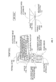
- FIG. 7 is a block diagram illustrating a portable holographic user interface displaying a holographic keyboard according to an example embodiment of the present invention.
- FIG. 8 is a flow chart diagram illustrating a method for providing a 3-dimensional (3-D) interface with a system to display a holographic keyboard according to an example embodiment of the present invention.
- the present invention in accordance with one embodiment relates to the creation of a holographic user interface which transforms the computing environment to enable a three-dimensional (3-D) holographic style user interface and display system.
- the system utilizes holographic projection technology along with programmed quadrant matrixes sensor field to create multiple methods to select and interact with data and user interface tools and icons presented in a holographic format.
- FIG. 1 illustrates a holographic user interface 100 according to one example embodiment of the present invention.
- the holographic user interface 100 includes a processor 114 that operates software 112 , controls a holographic image projector 116 , and processes information obtained from sensors 118 a , 118 b .
- the processor 114 receives user interaction information from the sensors 118 a , 118 b in response to the sensors 118 a , 118 b being activated upon interception of a path of the sensors 118 a , 118 b.
- the projector 116 may generate and display in a 3-D display image 101 , 102 within a 3-D coordinate system 150 in response to a user's desired selection.
- the displayed image 101 , 102 may be one type of holographic keyboard 605 ( FIG. 6 ) amongst a plurality of holographic keyboards.
- the sensors 118 a and 118 b may be directed toward the 3-D coordinate system to sense user interaction with images (e.g., holographic keyboard 605 ) within the 3-D coordinate system. If a user were to interact with an image 101 or 102 , the sensors 118 a and 118 b would provide coordinate information that the processor can correlate with the projected images 101 and 102 in the 3-D coordinate system.
- the interface 100 may communicate with a computer 120 to process and retrieve/store holograms 130 a , 130 b (collectively 130 ) in database 125 .
- the computer 120 may also include a software database to communicate with the processor 114 to provide logic for the sensors 118 a and 118 b to sense the user interaction and retrieve the displayed holographic keyboard.
- the computer 120 may be a separate standalone unit or be integrated with the interface 100 .
- the 3-D projector and interface 100 are capable of displaying the holographic keyboard on a variety of surfaces.
- the surface may be flat, contour, non-flat, or any combination thereof type of surfaces.
- the system relating holographic human machine interfaces between humans and electronic or electro-mechanical equipment is described in greater details in U.S. Pat. No. 6,377,238 entitled, “Holographic Control Arrangement”, which is hereby incorporated by reference in its entirety.
- Another system that relates to holographic human machine interfaces is U.S. Pat. No. 7,054,045 entitled, “Holographic Human-Machine Interfaces”, which is hereby incorporated by reference in its entirety.
- For more details on a holographic keyboard to display on a flat surface is described in greater details in U.S. Published patent application Number 2002/0070921 entitled, “Holographic Keyboard”, which is hereby incorporated by reference in its entirety.
- the interface 100 may project the holographic keyboard in thin air rather than on a surface.
- the database 125 may store the plurality of holograms 130 having a variety of different type of keyboards 605 .
- the database 125 may communicate with the 3-D projector 116 via the interface 100 to generate and display the one type of keyboard 605 .
- FIG. 2 is a flow chart that illustrates the method for providing a 3-dimensional (3-D) interface with a system.
- the interface generates ( 210 ) an image in a 3-D coordinate system.
- an embodiment of the interface deploys holographic information in the form of a user interface template as a default once turned on.
- Sensors on the interface sense ( 220 ) a user's interaction with the 3-D coordinate system. The sensing may occur through the use of matrixes or triangulated data points that correspond to specific functions and data display which the system is capable of displaying.
- the interface may then correlate ( 230 ) the user's interaction with an image in the 3-D coordinate system.
- the interface By sensing and correlating interaction with the 3-D coordinate system, the interface allows a computer system or display to interact with a user.
- the holographic data displayed by the system becomes a result of a selection process by the user who triggers data being displayed by key strokes or by the use of a three-dimensional interactive interface. Users' location commands are read by the system at their exact points and then the system deploys the appropriate response or holographic media based upon the users' specific request made via the location of that request.
- FIG. 3 illustrates a sensor field used in connection with embodiments of the present invention.
- the embodiment illustrated in FIG. 3 includes four laser sensors 320 a - d .
- the manipulatable interface may be a relatable and interactive holographic media via the use of a sprocketed sensor system which deploys from the display either via a built in or retrofit hardware peripheral that creates a quadrilateral angle navigation system to determine the exact point 330 of a fingertip touch point 340 within a quadrant 310 (also referred to as a “3-D coordinate system”).
- This touch point if effectively deployed by the user, is mapped to the image deployed by the holographic hardware and software system, as each image that is displayed in the system is displayed from an exacting point at an exacting place in space that has been preconfigured to match specific points on the quadrilateral sensor system.
- the points in space attached to programmed images are then matched to touch points made by the user.
- the touch point may trigger the same functions as a mouse and cursor.
- the sensors 118 a , 118 b may be activated upon the interception of the path by a user placing a finger (e.g., 340 ) through a key of the holographic keyboard 605 .
- the sensors may be laser sensors configured to provide data to triangulate a point within the 3-D coordinate system, photo voltaic sensors, photo electric light sensors, or image sensors.
- the sensors may be programmed to identify the specific location of the touchpoint 330 that may extend through multiple planar images, to identify a single image located at a 3-D coordinate space.
- FIG. 4 illustrates a holographic user interface device 400 according to one embodiment of the present invention.
- the device 400 has a port 410 that may provide the output projector for the multi-dimensional display, and also the sensors for detecting user interaction.
- the projector and sensors map out a 3-D coordinate system 420 to serve as the holographic user interface.
- a communications port 430 such as a universal serial bus (“USB”) port or wireless connection, serves to allow the device 400 to communicate with a computer system.
- the holographic system may be based upon our prior holographic system technology filing where the User Interface icons and documents may be saved to a fixed media form and activated by commands sent from the operating system to the device managing the index on the holographic fixed media system and display. Similarly, any system that utilizes holographic displays may also be manipulated and selected using the sensor interface system.
- FIG. 5 is a perspective view of a diagram of a holographic user interface 500 according to another embodiment of the present invention.
- the holographic user interface device may operate with a projection screen 580 .
- Images 505 displayed by the projection screen 580 of the user interface 500 can include shapes, graphic images, animation sequences, documents, audiovisual programs, a logical display based upon the users' patterns of use with the system (such as always going online first, always working on a word document second and always viewing pictures or videos from the users' hard drive.
- these icons could be presented to the user in an order of priority on the display representing the users' evolving use habits based upon history, including distinct changes based upon day, time and date), traditional UI operating system icons, such as Word document icons and portable document format (“PDF”) icons may be presented in a holographic format. Documents may be revised and read through in a traditional manner or documents, or any displayed item may revert back to the flat display monitor based upon user command.
- traditional UI operating system icons such as Word document icons and portable document format (“PDF”) icons may be presented in a holographic format. Documents may be revised and read through in a traditional manner or documents, or any displayed item may revert back to the flat display monitor based upon user command.
- PDF portable document format
- FIG. 6 is a block diagram illustrating a holographic user interface 100 displaying a holographic keyboard 605 according to an example embodiment of the present invention.
- a holographic user interface 100 displaying a holographic keyboard 605 according to an example embodiment of the present invention.
- many keyboards operate on the same principle, there are many variations of the type of keyboards from computer keyboards to typewriter-like keyboards.
- QWERTY keyboard developed by Sholes is now the official standard of computer keyboards ISO9995.
- Another type of keyboard is the Dvorak Keyboard that is easier and faster to type on when compared with other keyboards.
- the Chicklet keyboard is another type that is very small keyboard.
- the interface 100 is capable of changing the size and type of keyboards 605 so that it is more ergonomic. This feature may be advantageous to prevent health issues related to typing such as carpal tunnel syndrome.
- Carpal Tunnel Syndrome is an inflammatory disorder that affects the carpal (wrist) part of a specific nerve. Repetitive stress, physical trauma, certain diseases, or specific hereditary conditions can inflame the sheaths that surround wrist tendons. With the swelling of small blood vessels, pressure increases on the nerve and disrupts its functioning; numbness, pain, and a loss of manual dexterity result. Carpal Tunnel Syndrome may occur as a user does repetitive motion on his/her keyboard.
- the interface 100 may communicate with a computer 120 for data exchange, in particular the retrieval of a user's desired type of hologram 130 stored in the database 125 .
- the desired hologram 130 is then used by the interface 100 to project the holographic keyboard 605 .
- the interface 100 may alter the size and shape of the keyboard 605 in accordance to a user's desire. Moreover, as the 3-D projector via the interface 100 may expand/enlarge a key as a user's finger approaches the key.
- the holographic keyboard 605 has a plurality of keys, each key corresponding to a letter of the alphabet, a punctuation mark, symbol, or number.
- FIG. 7 is a block diagram illustrating a portable holographic user interface 700 displaying a holographic keyboard 605 according to an example embodiment of the present invention.
- the user interface 100 may be integrated with a portable device 700 , such as a cell phone.
- the portable device 700 may include a button 710 to trigger the holographic projector 116 to display the holographic keyboard 605 .
- the portable device 700 may also include other buttons, such as button 705 to adjust the size and shape of the holographic keyboard 605 to a user's desire.
- the portable device 700 exhibits the versatility of being able to have various types of keyboards and the ergonomic features, such as the ability to alter the size and shape of the keyboards.
- the keypads on the keyboard 605 may also be adjusted to accommodate the user.
- the portable device 700 may include a sound sensor system 720 to receive a user's voice to activate a key of the holographic keyboard.
- the interface By sensing and correlating interaction with the 3-D coordinate system, the interface allows a computer system or display to interact with a user.
- the holographic data displayed by the system becomes a result of a selection process by the user who triggers data being displayed by key strokes or by the use of a three-dimensional interactive interface. For example, if a user says “R” into the sound sensor 720 , the letter “R” appears on a monitor, such as a computer monitor (not shown).
- FIG. 8 is a flow chart diagram illustrating a method for providing a 3-dimensional (3-D) interface with a system to display a holographic keyboard (e.g., 605 ).
- the interface generates and displays one type of holographic keyboard amongst a plurality of holographic keyboards in a 3-D coordinate system in response to a user's desired selection ( 810 ).
- an embodiment of the interface deploys holographic information in the form of a user interface template as a default once turned on.
- the interface may store/load a plurality of holograms ( 820 ).
- the at least one database communicates with the 3-D projector to generate and display the one type of holographic keyboard.
- Sensors on the interface sense user interaction within the holographic keyboard in the 3-D ( 830 ).
- the sensing may occur through the use of matrixes or triangulated data points that correspond to specific functions and data displays which the system is capable of displaying.
- the interface may then correlate the user's interaction with the keyboard in the 3-D coordinate system.
- the interface receives user interaction information in response to a plurality of sensors being activated upon interception of a path of the plurality of sensors ( 840 ).
- the plurality of sensors can be activated.
- a Light Amplification by Stimulated Emission of Radiation (LASER) may intercept or break the path of the plurality of sensors.
- the holographic interface may include a holographic mouse in addition to the holographic keyboard. In such a situation, the holographic mouse may activate the plurality of sensors by clicking on a button on the mouse.
- the holographic mouse is further explained in details in U.S. patent application Ser. No. ______ entitled, “Method and Apparatus for User Interface of Input Devices” by Gene S.
- the interface may include a sound sensor 720 to receive a user's voice to activate a key of the holographic keyboard.
- the interface allows a computer system or display to interact with a user.
- the holographic data displayed by the system becomes a result of a selection process by the user who triggers data being displayed by key strokes or by the use of a three-dimensional interactive interface.
- Users' location commands are read by the system at their exact points and then the system deploys the appropriate response or holographic media based upon the users' specific request made via the location of that request.
- the interface may store/load software to provide logic for operability of the plurality of sensors to sense the user interaction and for retrieving the displayed holographic keyboard ( 850 ).
- a computer usable medium can include a readable memory device, such as a solid state memory device, a hard drive device, a CD-ROM, a DVD-ROM, or a computer diskette, having stored computer-readable program code segments.
- the computer readable medium can also include a communications or transmission medium, such as electromagnetic signals propagating on a computer network, a bus or a communications link, either optical, wired, or wireless, carrying program code segments as digital or analog data signals.
- the program code enables and supports computer implementation of the operations described in FIGS. 1 , 2 , 6 , 7 , 8 or other embodiments.
Abstract
Description
Claims (25)
Priority Applications (1)
| Application Number | Priority Date | Filing Date | Title |
|---|---|---|---|
| US11/932,731 US8212768B2 (en) | 2007-10-31 | 2007-10-31 | Digital, data, and multimedia user interface with a keyboard |
Applications Claiming Priority (1)
| Application Number | Priority Date | Filing Date | Title |
|---|---|---|---|
| US11/932,731 US8212768B2 (en) | 2007-10-31 | 2007-10-31 | Digital, data, and multimedia user interface with a keyboard |
Publications (2)
| Publication Number | Publication Date |
|---|---|
| US20090109176A1 US20090109176A1 (en) | 2009-04-30 |
| US8212768B2 true US8212768B2 (en) | 2012-07-03 |
Family
ID=40582229
Family Applications (1)
| Application Number | Title | Priority Date | Filing Date |
|---|---|---|---|
| US11/932,731 Active 2030-09-07 US8212768B2 (en) | 2007-10-31 | 2007-10-31 | Digital, data, and multimedia user interface with a keyboard |
Country Status (1)
| Country | Link |
|---|---|
| US (1) | US8212768B2 (en) |
Cited By (9)
| Publication number | Priority date | Publication date | Assignee | Title |
|---|---|---|---|---|
| US20120146897A1 (en) * | 2009-08-28 | 2012-06-14 | National Institute Of Information And Communications Technology | Three-dimensional display |
| US20120274658A1 (en) * | 2010-10-14 | 2012-11-01 | Chung Hee Sung | Method and system for providing background contents of virtual key input device |
| US8902225B2 (en) | 2007-10-31 | 2014-12-02 | Genedics Llc | Method and apparatus for user interface communication with an image manipulator |
| US9110563B2 (en) | 2007-10-31 | 2015-08-18 | Genedics Llc | Method and apparatus for user interface of input devices |
| US9548012B1 (en) * | 2012-08-29 | 2017-01-17 | Amazon Technologies, Inc. | Adaptive ergonomic keyboard |
| US9713871B2 (en) | 2015-04-27 | 2017-07-25 | Microsoft Technology Licensing, Llc | Enhanced configuration and control of robots |
| US10007413B2 (en) | 2015-04-27 | 2018-06-26 | Microsoft Technology Licensing, Llc | Mixed environment display of attached control elements |
| US11420846B2 (en) | 2018-03-13 | 2022-08-23 | Otis Elevator Company | Augmented reality car operating panel |
| US20230031200A1 (en) * | 2021-07-30 | 2023-02-02 | Jadelynn Kim Dao | Touchless, Gesture-Based Human Interface Device |
Families Citing this family (20)
| Publication number | Priority date | Publication date | Assignee | Title |
|---|---|---|---|---|
| US20150121287A1 (en) * | 2006-07-03 | 2015-04-30 | Yoram Ben-Meir | System for generating and controlling a variably displayable mobile device keypad/virtual keyboard |
| US20090102603A1 (en) * | 2007-10-19 | 2009-04-23 | Fein Gene S | Method and apparatus for providing authentication with a user interface system |
| US20090109174A1 (en) * | 2007-10-30 | 2009-04-30 | Fein Gene S | Method and Apparatus for User Interface in Electronic Devices With Visual Display Units |
| US8127251B2 (en) * | 2007-10-31 | 2012-02-28 | Fimed Properties Ag Limited Liability Company | Method and apparatus for a user interface with priority data |
| US20110080472A1 (en) * | 2009-10-02 | 2011-04-07 | Eric Gagneraud | Autostereoscopic status display |
| EP2363055A1 (en) | 2010-03-01 | 2011-09-07 | Electrolux Home Products Corporation N.V. | Projector and household appliance comprising such a projector |
| CN102339131A (en) * | 2010-07-16 | 2012-02-01 | 宸鸿光电科技股份有限公司 | Keyboard, electronic device using same and inputting method |
| CN102073393B (en) * | 2010-11-10 | 2013-06-12 | 友达光电股份有限公司 | Method applied to three-dimensional pointing system |
| CN102262301A (en) * | 2010-11-18 | 2011-11-30 | 宸鸿光电科技股份有限公司 | Holographic stereo image projection apparatus, application in electronic product thereof, application method thereof |
| KR101758163B1 (en) * | 2010-12-31 | 2017-07-14 | 엘지전자 주식회사 | Mobile terminal and hologram controlling method thereof |
| US8860688B2 (en) * | 2011-03-02 | 2014-10-14 | Smart Technologies Ulc | 3D interactive input system and method |
| US9294614B2 (en) * | 2011-08-24 | 2016-03-22 | Lg Electronics Inc. | Mobile terminal and controlling method thereof |
| KR101846168B1 (en) * | 2011-08-26 | 2018-04-06 | 엘지전자 주식회사 | Mobile terminal and method for controlling thereof |
| CN102855087A (en) * | 2012-09-12 | 2013-01-02 | 中兴通讯股份有限公司 | Input method, device and terminal |
| US20140111479A1 (en) * | 2012-10-24 | 2014-04-24 | Apple Inc. | Interactive Three-Dimensional Display System |
| US11449146B2 (en) | 2015-06-10 | 2022-09-20 | Wayne Patrick O'Brien | Interactive holographic human-computer interface |
| US10275098B1 (en) * | 2015-07-12 | 2019-04-30 | sigmund lindsay clements | Laser mid-air hologram touch input buttons for a device |
| US10318225B2 (en) * | 2015-09-01 | 2019-06-11 | Microsoft Technology Licensing, Llc | Holographic augmented authoring |
| US10571863B2 (en) * | 2017-12-21 | 2020-02-25 | International Business Machines Corporation | Determine and project holographic object path and object movement with mult-device collaboration |
| US11188154B2 (en) * | 2018-05-30 | 2021-11-30 | International Business Machines Corporation | Context dependent projection of holographic objects |
Citations (42)
| Publication number | Priority date | Publication date | Assignee | Title |
|---|---|---|---|---|
| US4593967A (en) | 1984-11-01 | 1986-06-10 | Honeywell Inc. | 3-D active vision sensor |
| US4818048A (en) * | 1987-01-06 | 1989-04-04 | Hughes Aircraft Company | Holographic head-up control panel |
| US5675437A (en) * | 1992-11-27 | 1997-10-07 | Voxel | Light control film for use in viewing holograms and related method |
| US5812292A (en) | 1995-11-27 | 1998-09-22 | The United States Of America As Represented By The Secretary Of The Navy | Optical correlator using optical delay loops |
| US6031519A (en) | 1997-12-30 | 2000-02-29 | O'brien; Wayne P. | Holographic direct manipulation interface |
| US6147773A (en) | 1995-09-05 | 2000-11-14 | Hewlett-Packard Company | System and method for a communication system |
| US6243054B1 (en) | 1998-07-01 | 2001-06-05 | Deluca Michael | Stereoscopic user interface method and apparatus |
| US6377238B1 (en) | 1993-04-28 | 2002-04-23 | Mcpheters Robert Douglas | Holographic control arrangement |
| US6388657B1 (en) | 1997-12-31 | 2002-05-14 | Anthony James Francis Natoli | Virtual reality keyboard system and method |
| US20020070921A1 (en) | 2000-12-13 | 2002-06-13 | Feldman Stephen E. | Holographic keyboard |
| US20020075240A1 (en) | 2000-05-29 | 2002-06-20 | Vkb Inc | Virtual data entry device and method for input of alphanumeric and other data |
| US6507353B1 (en) | 1999-12-10 | 2003-01-14 | Godot Huard | Influencing virtual actors in an interactive environment |
| US6650318B1 (en) * | 2000-10-13 | 2003-11-18 | Vkb Inc. | Data input device |
| US6667751B1 (en) | 2000-07-13 | 2003-12-23 | International Business Machines Corporation | Linear web browser history viewer |
| US20040095315A1 (en) | 2002-11-12 | 2004-05-20 | Steve Montellese | Virtual holographic input method and device |
| US20040106090A1 (en) | 2002-11-11 | 2004-06-03 | The Greenfield Group | System and method of facilitating and evaluating user thinking about an arbitrary problem using an archetype process |
| US20040119746A1 (en) | 2002-12-23 | 2004-06-24 | Authenture, Inc. | System and method for user authentication interface |
| US20040193441A1 (en) * | 2002-10-16 | 2004-09-30 | Altieri Frances Barbaro | Interactive software application platform |
| US20050140660A1 (en) * | 2002-01-18 | 2005-06-30 | Jyrki Valikangas | Method and apparatus for integrating a wide keyboard in a small device |
| US20050277467A1 (en) | 2004-06-14 | 2005-12-15 | Jcm American Corporation, A Nevada Corporation | Gaming machine using holographic imaging |
| US20050289472A1 (en) | 2004-06-29 | 2005-12-29 | Ge Medical Systems Information Technologies, Inc. | 3D display system and method |
| US20060098089A1 (en) | 2002-06-13 | 2006-05-11 | Eli Sofer | Method and apparatus for a multisensor imaging and scene interpretation system to aid the visually impaired |
| US7054045B2 (en) | 2003-07-03 | 2006-05-30 | Holotouch, Inc. | Holographic human-machine interfaces |
| US20060167971A1 (en) | 2004-12-30 | 2006-07-27 | Sheldon Breiner | System and method for collecting and disseminating human-observable data |
| US20060229108A1 (en) | 2005-02-04 | 2006-10-12 | Cehelnik Thomas G | Mobile phone extension and data interface via an audio headset connection |
| US7185271B2 (en) | 2002-08-20 | 2007-02-27 | Hewlett-Packard Development Company, L.P. | Methods and systems for implementing auto-complete in a web page |
| US20070130128A1 (en) | 2005-11-23 | 2007-06-07 | Veveo, Inc. | System and method for finding desired results by incremental search using an ambiguous keypad with the input containing orthographic and typographic errors |
| US20070169066A1 (en) | 2005-11-17 | 2007-07-19 | Nielsen Spencer J | System and method for an extensible 3D interface programming framework |
| US20070183012A1 (en) | 2006-01-24 | 2007-08-09 | Cadet Olivier J | Holographic display and controls applied to gas installations |
| US7262783B2 (en) | 2004-03-03 | 2007-08-28 | Virtual Iris Studios, Inc. | System for delivering and enabling interactivity with images |
| US20070211023A1 (en) | 2006-03-13 | 2007-09-13 | Navisense. Llc | Virtual user interface method and system thereof |
| US20070266428A1 (en) | 2006-03-06 | 2007-11-15 | James Downes | Method, System, And Apparatus For Nested Security Access/Authentication |
| US7312786B2 (en) | 2000-05-22 | 2007-12-25 | Qinetiq Limited | Three dimensional human-computer interface |
| US20080005703A1 (en) | 2006-06-28 | 2008-01-03 | Nokia Corporation | Apparatus, Methods and computer program products providing finger-based and hand-based gesture commands for portable electronic device applications |
| US20090102603A1 (en) | 2007-10-19 | 2009-04-23 | Fein Gene S | Method and apparatus for providing authentication with a user interface system |
| US20090109175A1 (en) | 2007-10-31 | 2009-04-30 | Fein Gene S | Method and apparatus for user interface of input devices |
| US20090113348A1 (en) | 2007-10-31 | 2009-04-30 | Fein Gene S | Method and apparatus for a user interface with priority data |
| US20090109215A1 (en) | 2007-10-31 | 2009-04-30 | Fein Gene S | Method and apparatus for user interface communication with an image manipulator |
| US20090109174A1 (en) | 2007-10-30 | 2009-04-30 | Fein Gene S | Method and Apparatus for User Interface in Electronic Devices With Visual Display Units |
| US20090267895A1 (en) * | 2005-09-23 | 2009-10-29 | Bunch Jesse C | Pointing and identification device |
| US7634741B2 (en) | 2004-08-31 | 2009-12-15 | Sap Ag | Method and apparatus for managing a selection list based on previous entries |
| US7844599B2 (en) | 2005-08-24 | 2010-11-30 | Yahoo! Inc. | Biasing queries to determine suggested queries |
-
2007
- 2007-10-31 US US11/932,731 patent/US8212768B2/en active Active
Patent Citations (44)
| Publication number | Priority date | Publication date | Assignee | Title |
|---|---|---|---|---|
| US4593967A (en) | 1984-11-01 | 1986-06-10 | Honeywell Inc. | 3-D active vision sensor |
| US4818048A (en) * | 1987-01-06 | 1989-04-04 | Hughes Aircraft Company | Holographic head-up control panel |
| US5675437A (en) * | 1992-11-27 | 1997-10-07 | Voxel | Light control film for use in viewing holograms and related method |
| US6377238B1 (en) | 1993-04-28 | 2002-04-23 | Mcpheters Robert Douglas | Holographic control arrangement |
| US6147773A (en) | 1995-09-05 | 2000-11-14 | Hewlett-Packard Company | System and method for a communication system |
| US5812292A (en) | 1995-11-27 | 1998-09-22 | The United States Of America As Represented By The Secretary Of The Navy | Optical correlator using optical delay loops |
| US6031519A (en) | 1997-12-30 | 2000-02-29 | O'brien; Wayne P. | Holographic direct manipulation interface |
| US6388657B1 (en) | 1997-12-31 | 2002-05-14 | Anthony James Francis Natoli | Virtual reality keyboard system and method |
| US6243054B1 (en) | 1998-07-01 | 2001-06-05 | Deluca Michael | Stereoscopic user interface method and apparatus |
| US6507353B1 (en) | 1999-12-10 | 2003-01-14 | Godot Huard | Influencing virtual actors in an interactive environment |
| US7312786B2 (en) | 2000-05-22 | 2007-12-25 | Qinetiq Limited | Three dimensional human-computer interface |
| US7084857B2 (en) | 2000-05-29 | 2006-08-01 | Vkb Inc. | Virtual data entry device and method for input of alphanumeric and other data |
| US20020075240A1 (en) | 2000-05-29 | 2002-06-20 | Vkb Inc | Virtual data entry device and method for input of alphanumeric and other data |
| US6667751B1 (en) | 2000-07-13 | 2003-12-23 | International Business Machines Corporation | Linear web browser history viewer |
| US6650318B1 (en) * | 2000-10-13 | 2003-11-18 | Vkb Inc. | Data input device |
| US20020070921A1 (en) | 2000-12-13 | 2002-06-13 | Feldman Stephen E. | Holographic keyboard |
| US7336263B2 (en) * | 2002-01-18 | 2008-02-26 | Nokia Corporation | Method and apparatus for integrating a wide keyboard in a small device |
| US20050140660A1 (en) * | 2002-01-18 | 2005-06-30 | Jyrki Valikangas | Method and apparatus for integrating a wide keyboard in a small device |
| US20060098089A1 (en) | 2002-06-13 | 2006-05-11 | Eli Sofer | Method and apparatus for a multisensor imaging and scene interpretation system to aid the visually impaired |
| US7185271B2 (en) | 2002-08-20 | 2007-02-27 | Hewlett-Packard Development Company, L.P. | Methods and systems for implementing auto-complete in a web page |
| US20040193441A1 (en) * | 2002-10-16 | 2004-09-30 | Altieri Frances Barbaro | Interactive software application platform |
| US20040106090A1 (en) | 2002-11-11 | 2004-06-03 | The Greenfield Group | System and method of facilitating and evaluating user thinking about an arbitrary problem using an archetype process |
| US20040095315A1 (en) | 2002-11-12 | 2004-05-20 | Steve Montellese | Virtual holographic input method and device |
| US20040119746A1 (en) | 2002-12-23 | 2004-06-24 | Authenture, Inc. | System and method for user authentication interface |
| US7054045B2 (en) | 2003-07-03 | 2006-05-30 | Holotouch, Inc. | Holographic human-machine interfaces |
| US7262783B2 (en) | 2004-03-03 | 2007-08-28 | Virtual Iris Studios, Inc. | System for delivering and enabling interactivity with images |
| US20050277467A1 (en) | 2004-06-14 | 2005-12-15 | Jcm American Corporation, A Nevada Corporation | Gaming machine using holographic imaging |
| US20050289472A1 (en) | 2004-06-29 | 2005-12-29 | Ge Medical Systems Information Technologies, Inc. | 3D display system and method |
| US7634741B2 (en) | 2004-08-31 | 2009-12-15 | Sap Ag | Method and apparatus for managing a selection list based on previous entries |
| US20060167971A1 (en) | 2004-12-30 | 2006-07-27 | Sheldon Breiner | System and method for collecting and disseminating human-observable data |
| US20060229108A1 (en) | 2005-02-04 | 2006-10-12 | Cehelnik Thomas G | Mobile phone extension and data interface via an audio headset connection |
| US7844599B2 (en) | 2005-08-24 | 2010-11-30 | Yahoo! Inc. | Biasing queries to determine suggested queries |
| US20090267895A1 (en) * | 2005-09-23 | 2009-10-29 | Bunch Jesse C | Pointing and identification device |
| US20070169066A1 (en) | 2005-11-17 | 2007-07-19 | Nielsen Spencer J | System and method for an extensible 3D interface programming framework |
| US20070130128A1 (en) | 2005-11-23 | 2007-06-07 | Veveo, Inc. | System and method for finding desired results by incremental search using an ambiguous keypad with the input containing orthographic and typographic errors |
| US20070183012A1 (en) | 2006-01-24 | 2007-08-09 | Cadet Olivier J | Holographic display and controls applied to gas installations |
| US20070266428A1 (en) | 2006-03-06 | 2007-11-15 | James Downes | Method, System, And Apparatus For Nested Security Access/Authentication |
| US20070211023A1 (en) | 2006-03-13 | 2007-09-13 | Navisense. Llc | Virtual user interface method and system thereof |
| US20080005703A1 (en) | 2006-06-28 | 2008-01-03 | Nokia Corporation | Apparatus, Methods and computer program products providing finger-based and hand-based gesture commands for portable electronic device applications |
| US20090102603A1 (en) | 2007-10-19 | 2009-04-23 | Fein Gene S | Method and apparatus for providing authentication with a user interface system |
| US20090109174A1 (en) | 2007-10-30 | 2009-04-30 | Fein Gene S | Method and Apparatus for User Interface in Electronic Devices With Visual Display Units |
| US20090113348A1 (en) | 2007-10-31 | 2009-04-30 | Fein Gene S | Method and apparatus for a user interface with priority data |
| US20090109215A1 (en) | 2007-10-31 | 2009-04-30 | Fein Gene S | Method and apparatus for user interface communication with an image manipulator |
| US20090109175A1 (en) | 2007-10-31 | 2009-04-30 | Fein Gene S | Method and apparatus for user interface of input devices |
Non-Patent Citations (10)
| Title |
|---|
| Final Office Action for U.S. Appl. No. 11/875,641, mailed Apr. 23, 2012. |
| Final Office Action for U.S. Appl. No. 11/875,641, mailed Jul. 19, 2011. |
| Final Office Action for U.S. Appl. No. 11/928,235, mailed on Oct. 11. 2011. |
| Non Final Office Action for U.S. Appl. No. 11/875,641, mailed on Sep. 29, 2011. |
| Non Final Office Action for U.S. Appl. No. 11/928,235, mailed Mar. 6, 2012. |
| Non Final Office Action for U.S. Appl. No. 11/932,372, mailed Jun. 21, 2011. |
| Notice of Allowance for U.S. Appl. No. 11/932,372, mailed Dec. 13, 2011. |
| Office Action for U.S. Appl. No. 11/875,641, mailed Feb. 16, 2011, 13 pages. |
| Office Action for U.S. Appl. No. 11/928,235, mailed Dec. 23, 2010, 19 pages. |
| Office Action for U.S. Appl. No. 11/928,235, mailed Jun. 6, 2011, 20 pages. |
Cited By (15)
| Publication number | Priority date | Publication date | Assignee | Title |
|---|---|---|---|---|
| US9335890B2 (en) | 2007-10-31 | 2016-05-10 | Genedics Llc | Method and apparatus for user interface of input devices |
| US9939987B2 (en) | 2007-10-31 | 2018-04-10 | Genedics Llc | Method and apparatus for user interface of input devices |
| US8902225B2 (en) | 2007-10-31 | 2014-12-02 | Genedics Llc | Method and apparatus for user interface communication with an image manipulator |
| US9110563B2 (en) | 2007-10-31 | 2015-08-18 | Genedics Llc | Method and apparatus for user interface of input devices |
| US8648773B2 (en) * | 2009-08-28 | 2014-02-11 | National Institute Of Information And Communications Technology | Three-dimensional display |
| US20120146897A1 (en) * | 2009-08-28 | 2012-06-14 | National Institute Of Information And Communications Technology | Three-dimensional display |
| US9329777B2 (en) * | 2010-10-14 | 2016-05-03 | Neopad, Inc. | Method and system for providing background contents of virtual key input device |
| US20120274658A1 (en) * | 2010-10-14 | 2012-11-01 | Chung Hee Sung | Method and system for providing background contents of virtual key input device |
| US9548012B1 (en) * | 2012-08-29 | 2017-01-17 | Amazon Technologies, Inc. | Adaptive ergonomic keyboard |
| US9713871B2 (en) | 2015-04-27 | 2017-07-25 | Microsoft Technology Licensing, Llc | Enhanced configuration and control of robots |
| US10007413B2 (en) | 2015-04-27 | 2018-06-26 | Microsoft Technology Licensing, Llc | Mixed environment display of attached control elements |
| US10099382B2 (en) | 2015-04-27 | 2018-10-16 | Microsoft Technology Licensing, Llc | Mixed environment display of robotic actions |
| US10449673B2 (en) | 2015-04-27 | 2019-10-22 | Microsoft Technology Licensing, Llc | Enhanced configuration and control of robots |
| US11420846B2 (en) | 2018-03-13 | 2022-08-23 | Otis Elevator Company | Augmented reality car operating panel |
| US20230031200A1 (en) * | 2021-07-30 | 2023-02-02 | Jadelynn Kim Dao | Touchless, Gesture-Based Human Interface Device |
Also Published As
| Publication number | Publication date |
|---|---|
| US20090109176A1 (en) | 2009-04-30 |
Similar Documents
| Publication | Publication Date | Title |
|---|---|---|
| US8212768B2 (en) | Digital, data, and multimedia user interface with a keyboard | |
| US8127251B2 (en) | Method and apparatus for a user interface with priority data | |
| CA2699560C (en) | Method and apparatus for holographic user interface communication | |
| US8902225B2 (en) | Method and apparatus for user interface communication with an image manipulator | |
| US20090102603A1 (en) | Method and apparatus for providing authentication with a user interface system | |
| US9335890B2 (en) | Method and apparatus for user interface of input devices | |
| Zhu et al. | Bishare: Exploring bidirectional interactions between smartphones and head-mounted augmented reality | |
| US11119718B2 (en) | Forming a larger display using multiple smaller displays | |
| Akaoka et al. | DisplayObjects: prototyping functional physical interfaces on 3d styrofoam, paper or cardboard models | |
| CN101512470B (en) | Information outputting device | |
| US20020070921A1 (en) | Holographic keyboard | |
| US20040233216A1 (en) | Data input/output system, data input/output method, and program recording medium | |
| US20090109174A1 (en) | Method and Apparatus for User Interface in Electronic Devices With Visual Display Units | |
| US8872813B2 (en) | Parallax image authoring and viewing in digital media | |
| Konieczny et al. | A handheld flexible display system | |
| CN105051621A (en) | Display device for holographic images for small- and medium-sized media devices | |
| WO2012008504A1 (en) | Information output device, medium, input processing system, and input-output processing system using stream dots | |
| Yamaguchi et al. | Interactive aerial-3D-touch holographic light-field display | |
| Tahir et al. | Interactive Slide Navigation: An Approach for Manipulating Slides with Augmented Reality Markers | |
| Wixson et al. | Managing windows as transparent PAGEs in a stereoscopic display | |
| JP2012022400A (en) | Information input auxiliary sheet and information processing system using stream dot | |
| Bimber et al. | Modern approaches to augmented reality Video files associated with this course are available from the citation page | |
| Wesche et al. | Immersive interaction |
Legal Events
| Date | Code | Title | Description |
|---|---|---|---|
| AS | Assignment |
Owner name: FIMED PROPERTIES AG LIMITED LIABILITY COMPANY, DEL Free format text: ASSIGNMENT OF ASSIGNORS INTEREST;ASSIGNOR:MERRITT, EDWARD;REEL/FRAME:020699/0866 Effective date: 20080229 Owner name: FIMED PROPERTIES AG LIMITED LIABILITY COMPANY, DEL Free format text: ASSIGNMENT OF ASSIGNORS INTEREST;ASSIGNOR:FEIN, GENE;REEL/FRAME:020699/0839 Effective date: 20080229 Owner name: FIMED PROPERTIES AG LIMITED LIABILITY COMPANY, DEL Free format text: ASSIGNMENT OF ASSIGNORS INTEREST;ASSIGNOR:GENEDICS LLC;REEL/FRAME:020699/0876 Effective date: 20080229 |
|
| AS | Assignment |
Owner name: FIMED PROPERTIES AG LIMITED LIABILITY COMPANY, DEL Free format text: ASSIGNMENT OF ASSIGNORS INTEREST;ASSIGNOR:MERRITT, EDWARD;REEL/FRAME:026017/0588 Effective date: 20110311 |
|
| STCF | Information on status: patent grant |
Free format text: PATENTED CASE |
|
| CC | Certificate of correction | ||
| FPAY | Fee payment |
Year of fee payment: 4 |
|
| AS | Assignment |
Owner name: F. POSZAT HU, L.L.C., DELAWARE Free format text: MERGER;ASSIGNOR:FIMED PROPERTIES AG LIMITED LIABILITY COMPANY;REEL/FRAME:037576/0197 Effective date: 20150812 |
|
| MAFP | Maintenance fee payment |
Free format text: PAYMENT OF MAINTENANCE FEE, 8TH YEAR, LARGE ENTITY (ORIGINAL EVENT CODE: M1552); ENTITY STATUS OF PATENT OWNER: LARGE ENTITY Year of fee payment: 8 |
|
| MAFP | Maintenance fee payment |
Free format text: PAYMENT OF MAINTENANCE FEE, 12TH YEAR, LARGE ENTITY (ORIGINAL EVENT CODE: M1553); ENTITY STATUS OF PATENT OWNER: LARGE ENTITY Year of fee payment: 12 |