US8213340B1 - System and method for managing a node split across multiple network elements - Google Patents
System and method for managing a node split across multiple network elements Download PDFInfo
- Publication number
- US8213340B1 US8213340B1 US11/203,787 US20378705A US8213340B1 US 8213340 B1 US8213340 B1 US 8213340B1 US 20378705 A US20378705 A US 20378705A US 8213340 B1 US8213340 B1 US 8213340B1
- Authority
- US
- United States
- Prior art keywords
- node
- network elements
- nodes
- network
- identification addresses
- Prior art date
- Legal status (The legal status is an assumption and is not a legal conclusion. Google has not performed a legal analysis and makes no representation as to the accuracy of the status listed.)
- Active, expires
Links
- 238000000034 method Methods 0.000 title claims description 37
- 238000004891 communication Methods 0.000 claims abstract description 69
- 230000001427 coherent effect Effects 0.000 claims abstract description 21
- 230000003287 optical effect Effects 0.000 claims description 9
- 230000001360 synchronised effect Effects 0.000 claims description 2
- 230000008878 coupling Effects 0.000 claims 2
- 238000010168 coupling process Methods 0.000 claims 2
- 238000005859 coupling reaction Methods 0.000 claims 2
- 230000008569 process Effects 0.000 description 10
- 238000012217 deletion Methods 0.000 description 5
- 230000037430 deletion Effects 0.000 description 5
- 238000010586 diagram Methods 0.000 description 5
- 230000009471 action Effects 0.000 description 2
- 230000002457 bidirectional effect Effects 0.000 description 2
- 238000013461 design Methods 0.000 description 2
- 238000010200 validation analysis Methods 0.000 description 2
- 230000004075 alteration Effects 0.000 description 1
- 230000008859 change Effects 0.000 description 1
- 238000012790 confirmation Methods 0.000 description 1
- 238000010276 construction Methods 0.000 description 1
- 238000006467 substitution reaction Methods 0.000 description 1
Images


Classifications
-
- H—ELECTRICITY
- H04—ELECTRIC COMMUNICATION TECHNIQUE
- H04L—TRANSMISSION OF DIGITAL INFORMATION, e.g. TELEGRAPHIC COMMUNICATION
- H04L12/00—Data switching networks
- H04L12/28—Data switching networks characterised by path configuration, e.g. LAN [Local Area Networks] or WAN [Wide Area Networks]
- H04L12/42—Loop networks
-
- H—ELECTRICITY
- H04—ELECTRIC COMMUNICATION TECHNIQUE
- H04L—TRANSMISSION OF DIGITAL INFORMATION, e.g. TELEGRAPHIC COMMUNICATION
- H04L41/00—Arrangements for maintenance, administration or management of data switching networks, e.g. of packet switching networks
- H04L41/12—Discovery or management of network topologies
Definitions
- the present invention relates in general to telecommunication network management techniques and more particularly to a system and method for managing a node split across multiple network elements.
- a node and its functionality is contained in a single network element. That network element is capable of providing full management of the node.
- telecommunication functionalities may be distributed across multiple network elements. Full management of distributed telecommunication functionalities becomes difficult to implement within an individual node.
- a system and method for managing a node split across multiple network elements are provided that substantially eliminate or greatly reduce disadvantages and problems associated with conventional telecommunication network management techniques.
- a system for managing a node split across multiple network elements that includes a communication ring having a plurality of links.
- the plurality of links couple a plurality of nodes in the communication ring.
- a particular one of the plurality of nodes has at least two network elements supported therein.
- a manager is operable to provide a coherent view of the two network elements in the particular node of the communication ring. In this manner, a manager can identify a node as being supported by two or more network elements and manage the telecommunication network according to how the functionalities of the particular node are split across the two or more network elements.
- the present invention provides various technical advantages over conventional telecommunication network management techniques. Some of these technical advantages are shown and described in the description of the present invention. Certain embodiments of the present invention may enjoy some, all, or none of these advantages. Other technical advantages may be readily apparent to one skilled in the art from the following figures, description, and claims.
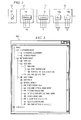
- FIG. 1 illustrates a simplified block diagram of a telecommunication network
- FIG. 2 illustrates a simplified block diagram of a network element in the telecommunication network
- FIG. 3 illustrates an example navigation tree generated by a manager in the telecommunication network
- FIG. 4 illustrates a process flow for node discovery in the telecommunication network
- FIG. 5 illustrates a process flow for defining a node in the telecommunication network
- FIG. 6 illustrates a process flow for link discovery in the telecommunication network
- FIG. 7 illustrates a process flow for defining a link in the telecommunication network
- FIG. 8 illustrates a process flow for ring discovery in the telecommunication network.
- FIG. 9 illustrates a simplified block diagram of the manager in the telecommunication network.
- FIG. 1 shows a block diagram of a telecommunication network 10 .
- Telecommunication network includes a plurality of nodes 12 , specifically identified as 12 a - n .
- the plurality of nodes 12 are coupled to one another by a communication ring 14 .
- Communication ring 14 may be implemented as one or more bidirectional links or one or more unidirectional links. Typically, for protection purposes, communication ring 14 has either two bidirectional links or four unidirectional links interconnecting nodes 12 .
- Communication ring 14 may establish a stand alone network, may be part of a multi-ring network, and may include linear spans to provide ring protection of a wavelength circuit across a dense wavelength division multiplexing (DWDM) network.
- DWDM dense wavelength division multiplexing
- communication ring 14 may be implemented in any manner and design according to a desired transport operation.
- Each node 12 provides a communication interface to the communication ring 14 for one or more end user telecommunication elements 16 .
- Each node 12 includes one or more network elements 18 that communicate with respective end user telecommunication elements 16 .
- end user telecommunication elements 16 may be a subscriber's telephone, a node for another telecommunication network, a routing device, or any other type of telecommunication device.
- Each node 12 includes one or more network elements 18 .
- a particular node 12 a includes a first network element 18 a and a second network element 18 b .
- Network elements 18 a and 18 b provide the telecommunication functionality for node 12 a within telecommunication network 10 .
- Network elements 18 a and 18 b may provide redundant operation to protect against a failure in either element, overflow operation to handle telecommunication data exchanges when one of the elements is at full capacity, or independent operation for telecommunication data exchange as desired.
- Network elements 18 a and 18 b may include line termination units that provide from zero to any number of connections to end user telecommunication elements 16 .
- FIG. 2 shows examples of network elements 18 a and 18 b .
- Network elements 18 a and 18 b may be deployed using compact optical add-drop multiplexers (COADM), single bay hub optical add-drop multiplexers (SBHOADM), back to back optical line terminals (OLT), optical line amplifiers (OLA), and SONET Multiplexer Transponder Modules (SMTM) as nodes 12 on communication ring 14 .
- COADM compact optical add-drop multiplexers
- SBHOADM single bay hub optical add-drop multiplexers
- OHT optical line terminals
- OOA optical line amplifiers
- SONET Multiplexer Transponder Modules SONET Multiplexer Transponder Modules
- Other conventional devices known to those skilled in the art may be used as network elements 18 .
- Each network element 18 may provide zero drops as a conventional OLA, four drops like a conventional COADM, sixteen drops like a SBHOADM, and thirty-two drops like a conventional OLT.
- Each network element 18 may have any other number
- telecommunication network 10 includes a manager 20 that supports management of communication ring 14 and network elements 18 at a physical and logical level.
- Functions capable of being performed by or through manager 20 include discovering and defining a node 12 and an OLT pair as a node 12 , a DWDM link, a network topology, and an interconnection path between two network elements 18 .
- Manager 20 may also delete a node 12 , a DWDM link, a communication ring 14 , and an interconnection path between two network elements 18 as well as edit their properties.
- Manager 20 may also handle situations that disrupt traffic such as adding and deleting a node 12 to communication ring 14 , splitting of communication ring 14 into two rings, and merging of two rings into a single ring. Nodes, links, and rings are established by manager 20 through definition by the user or discovery by manager 20 .
- FIG. 3 shows an example of a navigation tree 300 .
- Manager 20 creates navigation tree 300 to identify the topology of telecommunication network 10 .
- Navigation tree 300 provides an outline of the topology for telecommunication network 10 .
- Navigation tree 300 includes entries for each site, communication ring 14 , node 12 , network element 18 , and link 17 of telecommunication network 10 .
- a site may be a geographical location that includes one or more nodes 12 . Definition and discovery of entities within telecommunication network 10 are inserted into navigation tree 300 upon establishment of the topology for telecommunication network 10 .
- FIG. 4 shows a process flow 400 for discovering a node 12 by manager 20 .
- Manager 20 initiates discovery of a node as a sub-scenario of a user-initiated optical ring discovery request. If a network element is a COADM, SBHOADM, or OLA, the discovery is trivial as the two sides of the network element 18 comprise the node 12 .
- manager 20 For a pair of OLT units as network elements 18 a and 18 b being at node 12 a , manager 20 first retrieves the local and neighbor identification addresses of a starting network element 18 a of node 12 a at block 402 . Manager 20 then determines whether there is an existing definition for node 12 a and the starting network element 18 a at block 404 .
- manager 20 will validate that the definition matches the network connectivity. Manager 20 retrieves the local and neighbor identification addresses for the defined partner network element 18 b at block 406 . Manager 20 determines whether the addresses of the network elements 18 a and 18 b match up to provide a tight loop at block 408 . A tight loop occurs when the network elements 18 a and 18 b are shown to be chained together to provide a coherent connection. If there is a match, node 12 a is confirmed at block 410 . If there is a conflicting definition, a mismatch alarm is raised at block 412 for the node 12 and node 12 a is marked as unconfirmed at block 414 .
- the local and neighbor identification addresses for the network element(s) 18 b at that site are retrieved at block 416 and matched up to determine whether a tight loop occurs at block 418 . If there is a tight loop, node 12 a has been discovered for the network elements 18 a and 18 b at block 420 . If a tight loop is not present, there has been no discovery of node 12 a and a discovery failure is reported at block 422 . Once discovered, a node entity for the network elements 18 a and 18 b is created at block 424 and the navigation tree 300 is updated at block 426 by adding node 12 a under each OLT below the network root. The discovered node 12 a can now be used to support a communication ring 14 .
- FIG. 5 shows a process flow 500 for defining a node 12 by manager 20 .
- Manager 20 will allow a node 12 to be defined by a user. Once defined, validation of the connectivity of the defined node is performed by node discovery as discussed above. If a node to be defined includes a single network element 18 such as a COADM, SBHOADM, or OLA, the definition is automatic upon creation of the network element 18 since the two sides of these types of network elements 18 comprise a node 12 .
- a node to be defined includes a single network element 18 such as a COADM, SBHOADM, or OLA
- manager 20 For an OLT pair as network elements 18 a and 18 b at a node 12 a , manager 20 provides a user an ability to select at block 502 from the navigation tree 300 any OLT as network element 18 a for node 12 a that is not already associated with a communication ring 14 . The user then selects a second OLT as network element 18 b at block 504 . During selection of network elements 18 a and 18 b , the user assigns appropriate values to these entities. Once the OLT pair has been selected, manager 20 creates the node entity at block 506 and updates the navigation tree 300 at block 508 by adding node 12 a under each of the OLTs below the network root. Node 12 a can now be used to discover a communication ring 14 .
- FIG. 6 shows a process flow 600 for discovering a link 17 by manager 20 .
- Manager 20 initiates discovery of a link 17 as a sub-scenario of a user-initiated optical ring discovery request.
- Manager 20 retrieves the local and remote identification addresses for the starting OLT interfaces of the link 17 at block 602 .
- Manager 20 then retrieves the local and remote identification addresses of other network elements for the link 17 at block 604 .
- Manager 20 then matches up the addresses from the starting interface to those on a different network element interface at block 606 .
- Manager 20 will then confirm that the addresses match in the reverse direction at block 608 .
- Manager 20 determines whether there is an existing definition for link 17 at a specified interface at block 610 . If so, manager 20 will validate that the definition matches the network connectivity.
- any mismatch alarms are cleared at block 614 and the navigation tree 300 is updated accordingly at block 616 . If a mismatch occurs, a mismatch alarm is declared for the link 17 at block 618 . A link will not be discovered if a mismatch occurs and connectivity cannot be uniquely determined based on the identification addresses. If there is no existing link definition at block 610 , a site link is created at block 620 with a name, distance, and description if one does not already exist. Once discovered, a link entity for the OLT pair is created at block 622 and the navigation tree 300 is updated at block 624 by adding the link under each OLT below the network root. The discovered link can now be used to discover a communication ring 14 .
- FIG. 7 shows a process flow 700 for defining a link 17 by manager 20 .
- Manager 20 will allow a link 17 to be defined by a user. Once defined, validation of the connectivity of the defined link 17 is performed by the link discovery as discussed above.
- manager 20 provides a user at block 702 an ability to select from the navigation tree 300 any OLT to be linked that is not already associated with a communication ring 14 .
- manager 20 creates the link entity at block 704 and updates the navigation tree 300 at block 706 by adding the link 17 under each of the OLTs below the network root. The link 17 can now be used to discover a communication ring 14 .
- FIG. 8 shows a process flow 800 for discovering a network topology.
- Manager 20 provides a system behavior for discovering a physical protection ring. Manager 20 relies on the ability to discover and define links 17 and nodes 12 in order to discover a communication ring 14 topology. Discovery of communication ring 14 is user-invoked. A user selects a network element 18 , node 12 , or link 17 at block 802 to invoke discovery of the network topology. Manager 20 allows the user to define the name, description, and ring cost for communication ring 14 . If the entity from which discovery is invoked is part of a previously discovered communication ring 14 at block 804 , values from the previously discovered ring 14 are used as default values at block 806 .
- pre-determined default values may be used at block 808 .
- manager 20 chooses a direction of travel and attempts to construct communication ring 14 through alternating links 17 and nodes 12 at block 810 . If a node 12 or link 17 does not exist, manager 20 will attempt to discover the missing entity at block 812 . If manager 20 gets back to the invoking entity during the ring construction at block 814 , discovery of communication ring 14 is reported as successful at block 816 . If a conflicting entity is detected or a dead end reached, a discovery failure occurs and is reported at block 818 . Entities discovered during ring discovery will remain defined despite a discovery failure.
- manager 20 will update the set of alarms on the ring 14 at block 822 and update the ring definition at block 824 upon successful ring discovery. If there was no existing ring definition at block 820 , manager 20 creates a ring entity at block 826 with the values associated therewith, updates the alarms on the ring 14 at block 828 , and updates the navigation tree 300 at block 830 by adding the ring entity under the network root and copies the nodes 12 and links 17 beneath the ring entity in the navigation tree 300 .
- manager 20 will allow a user to view and modify the properties of communication ring 14 .
- Quality of service assignments for idle wavelengths can also be modified by the user.
- the user may view the outstanding network alarms that affect the ability of communication ring 14 to provide service.
- Manager 20 may also create a report upon request by the user of the characteristics and usage of communication ring 14 .
- the user can select a link 17 and request a wavelength summary report. From an arbitrary staring point, manager 20 will provide node 12 and link properties.
- a graphical representation of communication ring 14 including nodes 12 and links 17 , may be provided by manager 20 upon request. Manager 20 provides access for these features by presenting the navigation tree 300 to the user.
- a node 12 , a link 17 , or a communication ring 14 may be deleted from manager 20 upon request by a user. Discovery of communication ring 14 is irrelevant when deleting a node 12 or link 17 . From the navigation tree 300 , the user selects the node 12 , link 17 , or communication ring 14 that is to be deleted. For a link 17 supporting any circuits that have a quality of service other than Dedicated Protection, deletion of the link 17 may not be available. For a communication ring 14 supporting any circuits, the deletion action may not be available. Upon confirmation from the user, manager 20 will delete the node 12 , link 17 , or communication ring from its configuration and alarm databases. If the node 12 or link 17 was part of an existing communication ring 14 , an invalid alarm will be raised with respect to communication ring 14 . Manager 20 will then update the navigation tree 300 to remove the node 12 , link 17 , or communication ring 14 .
- addition or deletion of a node 12 may be performed through a link deletion and rediscovery action. Circuits with unprotected traffic that would be affected by the addition/deletion of a node 12 are deleted by manager 20 prior to rediscovery of communication ring 14 . Links 17 associated with the change in ring topology are deleted and rediscovery of communication ring 14 is initiated. For adding a node 12 , pass-through equipment and cross-connections are added at each additional node 12 as required supporting components for communication ring 14 . A best effort attempt is made to re-provision and enable the added equipment and cross-connections.
- Manager 20 updates the resources now required for communication ring 14 .
- FIG. 9 shows a simplified block diagram of manager 20 .
- Manager 20 may be implemented in hardware, software, a combination of hardware and software, or any other suitable logic or circuitry.
- Manager 20 may include a navigation tree generator functional module 900 , a node discovery functional module 902 , a node definition functional module 904 , a link discovery functional module 906 , a link definition functional module 908 , a ring discovery functional module 910 , and a controller functional module 912 . Though shown as separate functional modules, the operations provided by manager 20 may be included in fewer or more functional modules than depicted here. Each of the functional modules provide particular operations as discussed above. Controller functional module 912 may act as an interface between all functional modules and provide operational control for manager 20 .
- Manager 20 may also be provisioned to allow a user to define an interconnection link between two network elements 18 a and 18 b independent of an end-to-end circuit. From the navigation tree 300 , the user selects a network element 18 a and a source and a destination for the interconnection link. The source and destination include values associated with a site, network element, and port. Selection of ports may be limited to those that are compatible and not cross-connected. Upon selection of the source and destination for the interconnection link, manager 20 creates the interconnection link and adds it to the navigation tree 300 under each of the network elements 18 a and 18 b involved below the network root. The interconnection link can now be used for circuit definition. Once created, properties of the interconnection link can be viewed and modified.
- the properties include the name, description, and cost of the interconnection link. If not being used to support a circuit, an interconnection link may be deleted. Upon selection of an interconnection link, manager 20 verifies that the interconnection link is not being used in a circuit and removes it from the database. Manager 20 then updates the navigation tree 300 to reflect removal of the interconnection link.
- communication ring 14 may also be a Synchronous Optical Network (SONET) ring, a unidirectional path switched ring (UPSR), or any other type of conventional ring implementation.
- Links 17 may be DWDM links, carrier circuits, or any conventional interface implementations between network elements 18 .
- the functionalities of the node may be split across multiple network elements according to a desired design of telecommunication network 10 .
- the present invention allows a coherent view of a ring, nodes in the ring, and links therein, especially when a node is supported by two or more network elements. As a result, a node can be discovered, defined, and managed despite having its functionality split across more than one network element.
Abstract
Description
Claims (27)
Priority Applications (1)
| Application Number | Priority Date | Filing Date | Title |
|---|---|---|---|
| US11/203,787 US8213340B1 (en) | 2005-08-15 | 2005-08-15 | System and method for managing a node split across multiple network elements |
Applications Claiming Priority (1)
| Application Number | Priority Date | Filing Date | Title |
|---|---|---|---|
| US11/203,787 US8213340B1 (en) | 2005-08-15 | 2005-08-15 | System and method for managing a node split across multiple network elements |
Publications (1)
| Publication Number | Publication Date |
|---|---|
| US8213340B1 true US8213340B1 (en) | 2012-07-03 |
Family
ID=46320203
Family Applications (1)
| Application Number | Title | Priority Date | Filing Date |
|---|---|---|---|
| US11/203,787 Active 2028-01-10 US8213340B1 (en) | 2005-08-15 | 2005-08-15 | System and method for managing a node split across multiple network elements |
Country Status (1)
| Country | Link |
|---|---|
| US (1) | US8213340B1 (en) |
Cited By (2)
| Publication number | Priority date | Publication date | Assignee | Title |
|---|---|---|---|---|
| US20100239243A1 (en) * | 2007-12-07 | 2010-09-23 | Huawei Technologies Co., Ltd. | Pon ring system, and method for realizing primary and backup link protection in pon |
| US20140101301A1 (en) * | 2012-10-04 | 2014-04-10 | Stateless Networks, Inc. | System and Method for Dynamic Management of Network Device Data |
Citations (10)
| Publication number | Priority date | Publication date | Assignee | Title |
|---|---|---|---|---|
| US5014268A (en) * | 1989-01-11 | 1991-05-07 | Alcatel Na, Inc. | Parallel time slot interchanger matrix and switch block module for use therewith |
| US6108309A (en) * | 1997-12-08 | 2000-08-22 | Mci Communications Corporation | SONET network element simulator |
| US6147968A (en) * | 1998-10-13 | 2000-11-14 | Nortel Networks Corporation | Method and apparatus for data transmission in synchronous optical networks |
| US20010038612A1 (en) * | 1999-09-30 | 2001-11-08 | Darrell Vaughn | Automatic routing system for circuit layout |
| US20020141425A1 (en) * | 2001-03-30 | 2002-10-03 | Lalit Merani | Method and apparatus for improved queuing |
| US20020191617A1 (en) * | 2001-06-06 | 2002-12-19 | Luc Duplessis | System and method for transporting channelized ethernet over SONET/SDH |
| US6876625B1 (en) * | 2000-09-18 | 2005-04-05 | Alcatel Canada Inc. | Method and apparatus for topology database re-synchronization in communications networks having topology state routing protocols |
| US6920113B1 (en) * | 2000-03-28 | 2005-07-19 | Telsima Inc. | Transport of iscochronous and bursty data on a sonet ring |
| US20070025364A1 (en) * | 2005-08-01 | 2007-02-01 | Kodialam Muralidharan S | Characterizing achievable flow rates in multi-hop mesh networks with orthogonal channels |
| US7345993B2 (en) * | 2001-07-10 | 2008-03-18 | Lucent Technologies Inc. | Communication network with a ring topology |
-
2005
- 2005-08-15 US US11/203,787 patent/US8213340B1/en active Active
Patent Citations (10)
| Publication number | Priority date | Publication date | Assignee | Title |
|---|---|---|---|---|
| US5014268A (en) * | 1989-01-11 | 1991-05-07 | Alcatel Na, Inc. | Parallel time slot interchanger matrix and switch block module for use therewith |
| US6108309A (en) * | 1997-12-08 | 2000-08-22 | Mci Communications Corporation | SONET network element simulator |
| US6147968A (en) * | 1998-10-13 | 2000-11-14 | Nortel Networks Corporation | Method and apparatus for data transmission in synchronous optical networks |
| US20010038612A1 (en) * | 1999-09-30 | 2001-11-08 | Darrell Vaughn | Automatic routing system for circuit layout |
| US6920113B1 (en) * | 2000-03-28 | 2005-07-19 | Telsima Inc. | Transport of iscochronous and bursty data on a sonet ring |
| US6876625B1 (en) * | 2000-09-18 | 2005-04-05 | Alcatel Canada Inc. | Method and apparatus for topology database re-synchronization in communications networks having topology state routing protocols |
| US20020141425A1 (en) * | 2001-03-30 | 2002-10-03 | Lalit Merani | Method and apparatus for improved queuing |
| US20020191617A1 (en) * | 2001-06-06 | 2002-12-19 | Luc Duplessis | System and method for transporting channelized ethernet over SONET/SDH |
| US7345993B2 (en) * | 2001-07-10 | 2008-03-18 | Lucent Technologies Inc. | Communication network with a ring topology |
| US20070025364A1 (en) * | 2005-08-01 | 2007-02-01 | Kodialam Muralidharan S | Characterizing achievable flow rates in multi-hop mesh networks with orthogonal channels |
Cited By (5)
| Publication number | Priority date | Publication date | Assignee | Title |
|---|---|---|---|---|
| US20100239243A1 (en) * | 2007-12-07 | 2010-09-23 | Huawei Technologies Co., Ltd. | Pon ring system, and method for realizing primary and backup link protection in pon |
| US8768162B2 (en) * | 2007-12-07 | 2014-07-01 | Huawei Technologies Co., Ltd. | PON ring system, and method for realizing primary and backup link protection in PON |
| US20140101301A1 (en) * | 2012-10-04 | 2014-04-10 | Stateless Networks, Inc. | System and Method for Dynamic Management of Network Device Data |
| US10404555B2 (en) * | 2012-10-04 | 2019-09-03 | Fortinet, Inc. | System and method for dynamic management of network device data |
| US10511497B2 (en) * | 2012-10-04 | 2019-12-17 | Fortinet, Inc. | System and method for dynamic management of network device data |
Similar Documents
| Publication | Publication Date | Title |
|---|---|---|
| USRE43704E1 (en) | Determining and provisioning paths within a network of communication elements | |
| US7899326B2 (en) | System for utilizing wavelength reachability and wavelength occupation status information to describe cross-connection capabilities in optical networks | |
| US8327021B2 (en) | Technique of determining connectivity solutions for network elements | |
| US20060010441A1 (en) | Network management system | |
| US20050004999A1 (en) | Provisioning a network element using custom defaults | |
| US9112638B2 (en) | OSS support for control plane technology | |
| EP2096802B1 (en) | A hierarchical routing query method of automatic switched optical network | |
| US7414985B1 (en) | Link aggregation | |
| US7477843B1 (en) | Method of and system for routing in a photonic network | |
| US6721735B1 (en) | Method and apparatus for synchronizing databases in a network management system | |
| CA2382505C (en) | Control communications in communications networks | |
| US20040213166A1 (en) | Telecommunications network with automatic detection of the topology and method for this detection | |
| US8213340B1 (en) | System and method for managing a node split across multiple network elements | |
| CN101248700A (en) | Discovery of an adjacent network element within a network data plane | |
| US20030177213A1 (en) | Determining connectivity in communication networks | |
| JP4621228B2 (en) | Route searching method, apparatus and program in multi-layer network | |
| Wilson et al. | Multiwavelength optical networking management and control | |
| EP1551125B1 (en) | System and method for discovering wavelengths in network elements having an optical architecture | |
| CN101133601B (en) | Complex control node in automatic exchanging transmission network and control method thereof | |
| EP2285046A1 (en) | Method and apparatus for realizing interaction of optical channel data unit protection tangency rings | |
| US6697856B1 (en) | Healing of incomplete circuits in networks | |
| Lee et al. | Preserving survivability during logical topology reconfiguration in WDM ring networks | |
| JP2004274707A (en) | Method and apparatus for correlating optical cross-connect channel with non-related overhead | |
| Seshadri et al. | Distributed Network Restoration Using Multi-Sender Approach | |
| Gao et al. | Design and implementation of the management system for ASON with hierarchical routing architecture |
Legal Events
| Date | Code | Title | Description |
|---|---|---|---|
| AS | Assignment |
Owner name: TELLABS OPERATIONS, INC., ILLINOIS Free format text: ASSIGNMENT OF ASSIGNORS INTEREST;ASSIGNORS:GLICKLICH, BARRY;ALLABAUGH, DAVID;WILSON, PHILIPPE;REEL/FRAME:016894/0181 Effective date: 20050803 |
|
| STCF | Information on status: patent grant |
Free format text: PATENTED CASE |
|
| AS | Assignment |
Owner name: CERBERUS BUSINESS FINANCE, LLC, AS COLLATERAL AGEN Free format text: SECURITY AGREEMENT;ASSIGNORS:TELLABS OPERATIONS, INC.;TELLABS RESTON, LLC (FORMERLY KNOWN AS TELLABS RESTON, INC.);WICHORUS, LLC (FORMERLY KNOWN AS WICHORUS, INC.);REEL/FRAME:031768/0155 Effective date: 20131203 |
|
| FEPP | Fee payment procedure |
Free format text: PAYOR NUMBER ASSIGNED (ORIGINAL EVENT CODE: ASPN); ENTITY STATUS OF PATENT OWNER: LARGE ENTITY |
|
| AS | Assignment |
Owner name: TELECOM HOLDING PARENT LLC, CALIFORNIA Free format text: ASSIGNMENT FOR SECURITY - - PATENTS;ASSIGNORS:CORIANT OPERATIONS, INC.;TELLABS RESTON, LLC (FORMERLY KNOWN AS TELLABS RESTON, INC.);WICHORUS, LLC (FORMERLY KNOWN AS WICHORUS, INC.);REEL/FRAME:034484/0740 Effective date: 20141126 |
|
| FPAY | Fee payment |
Year of fee payment: 4 |
|
| AS | Assignment |
Owner name: TELECOM HOLDING PARENT LLC, CALIFORNIA Free format text: CORRECTIVE ASSIGNMENT TO CORRECT THE REMOVE APPLICATION NUMBER 10/075,623 PREVIOUSLY RECORDED AT REEL: 034484 FRAME: 0740. ASSIGNOR(S) HEREBY CONFIRMS THE ASSIGNMENT FOR SECURITY --- PATENTS;ASSIGNORS:CORIANT OPERATIONS, INC.;TELLABS RESTON, LLC (FORMERLY KNOWN AS TELLABS RESTON, INC.);WICHORUS, LLC (FORMERLY KNOWN AS WICHORUS, INC.);REEL/FRAME:042980/0834 Effective date: 20141126 |
|
| MAFP | Maintenance fee payment |
Free format text: PAYMENT OF MAINTENANCE FEE, 8TH YEAR, LARGE ENTITY (ORIGINAL EVENT CODE: M1552); ENTITY STATUS OF PATENT OWNER: LARGE ENTITY Year of fee payment: 8 |
|
| MAFP | Maintenance fee payment |
Free format text: PAYMENT OF MAINTENANCE FEE, 12TH YEAR, LARGE ENTITY (ORIGINAL EVENT CODE: M1553); ENTITY STATUS OF PATENT OWNER: LARGE ENTITY Year of fee payment: 12 |