US8258917B2 - Intuitive multiple degrees of freedom portable control device - Google Patents
Intuitive multiple degrees of freedom portable control device Download PDFInfo
- Publication number
- US8258917B2 US8258917B2 US13/034,079 US201113034079A US8258917B2 US 8258917 B2 US8258917 B2 US 8258917B2 US 201113034079 A US201113034079 A US 201113034079A US 8258917 B2 US8258917 B2 US 8258917B2
- Authority
- US
- United States
- Prior art keywords
- sensing device
- user
- motion
- displacement controller
- accordance
- Prior art date
- Legal status (The legal status is an assumption and is not a legal conclusion. Google has not performed a legal analysis and makes no representation as to the accuracy of the status listed.)
- Active, expires
Links
- 230000033001 locomotion Effects 0.000 claims abstract description 107
- 238000006073 displacement reaction Methods 0.000 claims abstract description 55
- 230000007246 mechanism Effects 0.000 claims abstract description 33
- 238000000034 method Methods 0.000 claims abstract description 29
- 230000008569 process Effects 0.000 claims abstract description 7
- 230000005358 geomagnetic field Effects 0.000 claims description 14
- 238000012544 monitoring process Methods 0.000 claims description 6
- 230000004913 activation Effects 0.000 claims description 5
- 238000012545 processing Methods 0.000 claims description 5
- 238000004891 communication Methods 0.000 claims description 4
- 239000002352 surface water Substances 0.000 claims description 4
- XLYOFNOQVPJJNP-UHFFFAOYSA-N water Substances O XLYOFNOQVPJJNP-UHFFFAOYSA-N 0.000 claims description 4
- 230000007613 environmental effect Effects 0.000 claims description 3
- 230000000694 effects Effects 0.000 claims description 2
- 230000011664 signaling Effects 0.000 claims description 2
- 238000012806 monitoring device Methods 0.000 claims 2
- 230000001276 controlling effect Effects 0.000 description 14
- 230000001133 acceleration Effects 0.000 description 7
- 230000000994 depressogenic effect Effects 0.000 description 5
- 210000003811 finger Anatomy 0.000 description 5
- 229920003259 poly(silylenemethylene) Polymers 0.000 description 5
- 230000009977 dual effect Effects 0.000 description 4
- 230000008901 benefit Effects 0.000 description 3
- 230000004044 response Effects 0.000 description 3
- 238000013459 approach Methods 0.000 description 2
- 230000003750 conditioning effect Effects 0.000 description 2
- 230000000881 depressing effect Effects 0.000 description 2
- 238000013461 design Methods 0.000 description 2
- 238000005516 engineering process Methods 0.000 description 2
- 210000005224 forefinger Anatomy 0.000 description 2
- 210000004247 hand Anatomy 0.000 description 2
- 230000010354 integration Effects 0.000 description 2
- 230000013011 mating Effects 0.000 description 2
- 238000005259 measurement Methods 0.000 description 2
- 238000012986 modification Methods 0.000 description 2
- 230000004048 modification Effects 0.000 description 2
- 238000002202 sandwich sublimation Methods 0.000 description 2
- 210000003813 thumb Anatomy 0.000 description 2
- RZVHIXYEVGDQDX-UHFFFAOYSA-N 9,10-anthraquinone Chemical compound C1=CC=C2C(=O)C3=CC=CC=C3C(=O)C2=C1 RZVHIXYEVGDQDX-UHFFFAOYSA-N 0.000 description 1
- 230000005355 Hall effect Effects 0.000 description 1
- 230000002411 adverse Effects 0.000 description 1
- 230000008859 change Effects 0.000 description 1
- 238000010276 construction Methods 0.000 description 1
- 230000006866 deterioration Effects 0.000 description 1
- 230000006870 function Effects 0.000 description 1
- 238000003384 imaging method Methods 0.000 description 1
- 230000007774 longterm Effects 0.000 description 1
- 230000007935 neutral effect Effects 0.000 description 1
- 230000003287 optical effect Effects 0.000 description 1
- 238000012546 transfer Methods 0.000 description 1
- 238000013519 translation Methods 0.000 description 1
- 230000014616 translation Effects 0.000 description 1
Images


Classifications
-
- G—PHYSICS
- G06—COMPUTING; CALCULATING OR COUNTING
- G06F—ELECTRIC DIGITAL DATA PROCESSING
- G06F3/00—Input arrangements for transferring data to be processed into a form capable of being handled by the computer; Output arrangements for transferring data from processing unit to output unit, e.g. interface arrangements
- G06F3/01—Input arrangements or combined input and output arrangements for interaction between user and computer
- G06F3/03—Arrangements for converting the position or the displacement of a member into a coded form
- G06F3/033—Pointing devices displaced or positioned by the user, e.g. mice, trackballs, pens or joysticks; Accessories therefor
- G06F3/0346—Pointing devices displaced or positioned by the user, e.g. mice, trackballs, pens or joysticks; Accessories therefor with detection of the device orientation or free movement in a 3D space, e.g. 3D mice, 6-DOF [six degrees of freedom] pointers using gyroscopes, accelerometers or tilt-sensors
-
- A—HUMAN NECESSITIES
- A63—SPORTS; GAMES; AMUSEMENTS
- A63F—CARD, BOARD, OR ROULETTE GAMES; INDOOR GAMES USING SMALL MOVING PLAYING BODIES; VIDEO GAMES; GAMES NOT OTHERWISE PROVIDED FOR
- A63F2300/00—Features of games using an electronically generated display having two or more dimensions, e.g. on a television screen, showing representations related to the game
- A63F2300/10—Features of games using an electronically generated display having two or more dimensions, e.g. on a television screen, showing representations related to the game characterized by input arrangements for converting player-generated signals into game device control signals
- A63F2300/105—Features of games using an electronically generated display having two or more dimensions, e.g. on a television screen, showing representations related to the game characterized by input arrangements for converting player-generated signals into game device control signals using inertial sensors, e.g. accelerometers, gyroscopes
Definitions
- This disclosure relates to control devices, and more particularly to portable devices for controlling other devices capable of movement with multiple degrees of freedom (including but not limited to vehicles).
- a control device for a vehicle or mechanism.
- This control device includes a portable displacement controller which permits a non-technical user to achieve effective control of the vehicle or mechanism, by moving the portable displacement controller intuitively with little learning effort.
- a control device includes a displacement controller operable by a user of the device.
- a first sensing device is attached to the displacement controller and is configured to detect a controlling motion performed by the user.
- a second sensing device is attached to the entity being controlled, the second sensing device configured to detect motion thereof.
- An interface device is operatively connected (via cable, or wirelessly) to the first sensing device and the second sensing device. The interface device is configured to receive signals from the first sensing device and from the second sensing device; to process those signals to determine relative motion of the controlling motion and the motion of the entity being controlled; and to output a control signal for controlling the entity in accordance with the processed signals.
- each of the first sensing device and the second sensing device is configured to detect motion in six degrees of freedom; each of the first and second sensing devices includes a three-axis accelerometer, a three-axis gyroscope, and a three-axis magnetometer.
- the accelerometers, gyroscopes, and magnetometers are micro-electromechanical system (MEMS) devices.
- MEMS micro-electromechanical system
- the first sensing device detects the controlling motion relative to a first reference frame in accordance with a geomagnetic field local to the first sensing device
- the second sensing device detects the motion of the entity relative to a second reference frame in accordance with a geomagnetic field local to the second sensing device.
- the displacement controller is wearable by the user; the displacement controller may be secured to the user's arm, hand or finger, to perform the controlling movement.
- a system for controlling a mechanism includes the above-described features and also includes an operating device (e.g. a host computing device) connected to the mechanism and configured to operate the mechanism.
- the interface device outputs a control signal to the operating device so as to control the mechanism in accordance with the processed signals.
- the mechanism is a vehicle; the second sensing device, the interface device, and the operating device are located on the vehicle; and the displacement controller has the first sensing device disposed therein and is remote from the vehicle.
- the displacement controller may be attachable to and detachable from a mounting base in the vehicle, or may be fixed thereto.
- FIG. 1 schematically illustrates a Primary Sensing Module (PSM) and Secondary Sensing Module (SSM) used in embodiments of the disclosure.
- PSM Primary Sensing Module
- SSM Secondary Sensing Module
- FIG. 2 schematically illustrates a sensing module measuring accelerations and angular rotation rates in its own body coordinate system, in accordance with embodiments of the disclosure.
- FIG. 3A illustrates a single handle control device according to an embodiment of the disclosure.
- FIG. 3B illustrates steps in a calibration method for the control device of FIG. 3A .
- FIGS. 4A and 4B are side and bottom views, respectively, of the single handle control device of FIG. 3A .
- FIG. 5 is a top view of a mounting base for mounting the single handle control device of FIG. 3A .
- FIG. 6 is a side view of the mounting base of FIG. 5 , suitable for attaching to a vehicle platform.
- FIG. 7 illustrates a dual handle control device according to another embodiment of the disclosure.
- FIG. 8 is a side view of the dual handle control device of FIG. 7 .
- FIG. 9 illustrates another dual handle control device, according to an additional embodiment of the disclosure.
- FIG. 10 is a side view of the dual handle control device of FIG. 9 .
- FIG. 11 schematically illustrates a Human Machine Interface (HMI) system including a Host Interface Module (HIM) connecting to a platform with an SSM, a controller with a single PSM, and to a host system, in accordance with an embodiment of the disclosure.
- HMI Human Machine Interface
- HIM Host Interface Module
- FIG. 12A schematically illustrates a Human Machine Interface (HMI) system including a Host Interface Module (HIM) connecting to a platform with an SSM, to a controller with a multiple PSMs, and to a host system, in accordance with another embodiment of the disclosure.
- HMI Human Machine Interface
- HIM Host Interface Module
- FIG. 12B schematically illustrates a moving platform communicating with a network of multiple interconnected PSMs, in accordance with another embodiment of the disclosure.
- FIG. 13 schematically illustrates components of a HIM.
- FIG. 14 schematically illustrates software executed by an HIM.
- a control device is a displacement type control device operated by a human hand or hands, or a body segment when a human hand is not accessible.
- the device does not have conventional movement sensors and does not require a kinematic mechanism.
- Direct motion measurement is achieved by employing a combination of MEMS (micro-electromechanical systems) sensors arranged into modules, as detailed below.
- MEMS micro-electromechanical systems
- Each MEMS sensing module contains a three-axis MEMS accelerometer, a three-axis MEMS gyroscope and a three-axis MEMS magnetometer in a compact package having a volume less than 0.2 cubic inch.
- Each module thus has the capability to measure acceleration, angular rotation rate and geomagnetic field in the sensing module's body coordinate system with respect to Earth. This capability provides a total of six degrees of freedom (DOFs), a significant advantage in terms of form factor over conventional electronic sensors.
- DOFs degrees of freedom
- a displacement controller embodying the disclosure offers the benefits of MEMS sensing technology, may be portable (or wearable), capable in multiple DOFs, and also adaptable to conventional devices involving kinematic mechanisms.
- a control device 1 includes a Primary Sensing Module (PSM) 11 and a Secondary Sensing Module (SSM) 12 .
- the PSM senses movement of a handle 13 , operated by a user of the device, relative to a platform 14 .
- MEMS inertial sensors rely on Earth's gravitational field for a reference frame, the effect of platform motions needs to be separated from the motions of control handle 13 ; this is done by measuring the platform motions using SSM 12 .
- the platform 14 serves as a reference frame for the motions of handle 13 ; the SSM senses movement of the platform relative to the environment.
- platform 14 might be installed in a moving vehicle whose motion is detected by SSM 12 , while PSM 11 measures motions of handle 13 held by an operator. It is not necessary for handle 13 to be physically connected to platform 14 .
- PSM 11 includes a three-axis MEMS accelerometer 15 , a three-axis MEMS gyroscope 16 , a three-axis MEMS magnetometer 17 , a temperature sensor 18 , and a signal conditioning circuit 19 in a compact package having a volume less than 0.2 cubic inch.
- PSM 11 is attached to handle 13 at any convenient location.
- SSM 12 likewise includes a three-axis MEMS accelerometer 15 , three-axis MEMS gyroscope 16 , three-axis MEMS magnetometer 17 , temperature sensor 18 and signal conditioning circuit 19 in a compact package with a volume less than 0.2 cubic inch.
- platform 14 is located where the control device is to be used; this may be (for example) a ground vehicle, a ship, or a human body.
- PSM 11 and SSM 12 have power inputs 5 , 6 and signal outputs 7 , 8 respectively.
- PSM 11 also has inputs labeled “Mode” 2 , “Reset” 3 and “Enable” 4 , discussed in detail below.
- PSM 11 and SSM 12 are connected to a host system through a Host Interface Module (HIM), as shown schematically in FIGS. 11-13 .
- HIM Host Interface Module
- Each sensing module 11 , 12 measures accelerations and angular rotation rates in its own body coordinate system.
- PSM 11 disposed in the lower portion of handle 13 , as shown by dashed lines
- PSM 11 measures accelerations of handle 13 in the x, y, and z linear directions and the pitch, roll, and yaw angular directions.
- Positional data including pitch, roll and yaw orientations are initially predicted using a navigation algorithm, discussed below with reference to FIG. 14 .
- FIG. 3A shows some details of a portable single handle device 20 according to an embodiment of the disclosure.
- Handle 13 has an ergonomic grip portion 31 at one end and is attached to mounting plate 35 at its other end.
- PSM 11 is mounted to the opposite side of mounting plate 35 and is enclosed by an adaptor 36 .
- adaptor 36 is configured for mechanical connection to a mounting base, using ball detents 37 ; adaptor 36 also includes an interface connector 38 when the connection to the mounting base is not wireless.
- Handle 13 is preferably rugged and ergonomically shaped for operation by a human hand or hands, or a body segment.
- grip portion 31 includes “Mode” and “Reset” switches 32 , 33 , the operation of which is described below.
- Grip portion 31 also has space to contain optional controls 28 such as switches, mini-joysticks, thumbwheels, etc. Controls and switches 28 , 32 , 33 in this portion of the handle are conveniently located for actuation by a user's thumb.
- inertial motion sensors are always live when powered, unintended movements of the handle may lead to output errors.
- errors are prevented by recognizing sensor signals from the PSM only when “Enable” switch 34 is activated.
- “Enable” switch 34 conveniently located for actuation by pressure from a user's palm, is activated only when depressed and deactivated when released.
- the host system connected to the device is notified when the “Enable” switch is deactivated, e.g. when the device is left unattended by the user or in the event the user accidentally drops the handle.
- the host system is configured to ignore undesired PSM outputs (that is, outputs while switch 34 is deactivated).
- one or more SSMs may be mounted on the user (e.g. secured to the user's hand, arm or finger, or attached to or built into the user's clothing) to detect and cancel unintended user motion relative to the displacement controller (in this embodiment, single handle device 20 ).
- “Reset” push button switch 33 is activated only when depressed and deactivated when released. Switch 33 is located for easy access as shown in FIG. 3A for a single handle grip (see FIG. 7 for a dual-handle grip).
- the host system responds to a “Reset” signal (that is, when switch 33 is depressed) by resetting the digital outputs to default null values set during a previous calibration, and re-centering the device's output positions. This is analogous to using mechanical springs to return a conventional positioning device to a center position. In portable device 20 , there is no mechanical force present to return to a center position; instead, device 20 includes a non-volatile memory and “Reset” switch 33 .
- the memory holds the previous center position data and is refreshed until the “Reset” switch is depressed and released.
- the “Reset” button may be used to reestablish the reference frame of either or both of the PSM and SSM.
- the “Reset” switch has additional functions when combined with the “Mode” switch 32 , as described below.
- grip portion 31 includes a “Hold” push button switch 39 ; depressing the “Hold” switch allows the user to bring the displacement controller back to a neutral position without altering the current displacement or orientation of the device under control (DUC).
- a robot arm could be moved forward 24 inches by moving the displacement controller forward 12 inches, depressing the “Hold” switch, returning the displacement controller to its previous position, releasing the switch, and again moving the displacement controller forward 12 inches.
- the user's controlling motion and the DUC motion have 1:1 scaling; other ratios may be used, as discussed below.
- “Mode” push button switch 32 is activated only when depressed for a period of approximately 5 to 10 seconds and then released. Activation of switch 32 causes the device to enter a calibration mode. The lengthened period required for activation ensures that the calibration mode is entered only when intended by the user.
- Steps in a calibration procedure for a displacement controller device are shown in the flowchart of FIG. 3B .
- the user depresses the “Mode” switch 32 for approximately 5 to 10 seconds, and then releases the switch, to activate the switch (step 381 ).
- the user then moves the device in a full range of directions intended for use, and the device learns the geomagnetic field in its surroundings and angles relative to earth's gravitational field (step 382 ).
- the user depresses and releases the “Reset” switch 33 (step 383 ).
- the device will then enter the calibration mode.
- the user moves the displacement controller device only in the directions to be used for control purposes (step 384 ). By default, the device assumes that all six DOFs will be used.
- the user may select only a particular combination of three translations and three rotations (out of a total number of possibilities of 64, or 2 6 )—an analogy to mechanical gating in conventional control devices.
- the device learns that combination from the user's gestures (step 385 ). If the user believes an error has been made (step 386 ), the user presses and releases the “Reset” button to re-start the calibration. The user presses and releases the “Mode” switch again (step 387 ) to complete the calibration and exit the procedure.
- a given user's set of motions and gestures may be applied to a variety of devices under control (DUCs).
- DUCs devices under control
- a given DUC might be controlled by any of a plurality of users with differing types and ranges of motion.
- a user's calibration motions and gestures accordingly may be scaled to represent the dynamics of a particular DUC controlled by that user. For example, a child controlling a toy might cause the toy to move 6 inches in response to a 12 inch motion (scale 1:2), while a disabled person controlling a full-size vehicle might cause the vehicle to move 5 feet in response to a 1 inch motion (scale 60:1).
- the system (which generally includes the displacement controller, HIM, SSM, and host system) may include a non-volatile memory and a display device, and may support control of a given DUC by a plurality of users, each having his/her own set of motions and gestures.
- the non-volatile memory is located either in the displacement controller, the HIM, or both.
- the calibration motions and gestures for each user may be stored in the non-volatile memory, and retrieved for use by the system in accordance with a user logging on to the system or selecting his/her name from a list of users displayed on the display device by the system.
- the system may also include a device for signaling to the user when the user executes a motion or gesture outside the range of calibrated motions.
- the system may be configured to perform a dynamic calibration of user motions (both intended and unintended motions) by monitoring and learning the dynamics of the system; that is, learning the types, DOF and range of motions performed by the user and detected by the displacement controller, by the SSM, and by the DUC.
- a dynamic calibration of user motions both intended and unintended motions
- the dynamics of the system that is, learning the types, DOF and range of motions performed by the user and detected by the displacement controller, by the SSM, and by the DUC.
- FIGS. 4A and 4B are side and bottom views, respectively, of the single-handle device of FIG. 3A .
- “Enable” switch 34 is shown in profile in FIG. 4A .
- handle 13 is gripped by the user so that “Enable” switch 34 is adjacent to the user's palm.
- a trigger-type switch 29 may be located on the same side of the handle, convenient to the user's forefinger.
- the bottom view of FIG. 4B shows fasteners 42 for the enclosure of PSM 11 , as well as ball detents 37 and alignment key 41 for positive mounting of adaptor 36 to the mounting base.
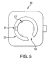
- FIGS. 5 and 6 are top and side views, respectively, of a mounting base 60 on which portable single handle device 20 (such as shown in FIGS. 3A and 4 ) is mounted, in accordance with an embodiment.
- mounting base 60 includes a cradle 50 for connecting to adaptor 36 .
- Cradle 50 includes a keyway 51 for mating with alignment key 41 , and ball plungers 57 for mating with ball detents 37 .
- cradle 50 has an opening 58 for the cable.
- Portable device 20 thus may be quickly attached to or detached from mounting base 60 . It will be appreciated that device portability removes the analogy for certain mechanical gating features such as cross-gate or speed shift gate.
- the adaptor 36 provides the user flexibility to switch between a portable device and a device fixed to base 60 , according to the user's preference.
- FIG. 6 shows additional details of mounting base 60 .
- Cradle 50 connects to the lower portion of the mounting base via a flexible bellows or collar 62 .
- mounting base 60 includes SSM 12 and HIM 61 , and interface connectors 67 , 68 for connecting to the host system and the PSM respectively.
- Mounting base 60 is configured for attachment to platform 14 .
- SSM 12 measures the motions of the vehicle and thus provides a frame of reference for the motions of the control handle.
- FIGS. 7 and 8 A dual-handle controller 70 , according to another embodiment of the disclosure, is shown in FIGS. 7 and 8 .
- Controller 70 has two ergonomic grip handles 751 , 752 ; the user may activate “Enable” switch 74 using either hand.
- PSM 11 is mounted in the central portion of the controller.
- Control panel 77 has space for various thumb-operated switches, including particularly “Mode” switch 32 and “Reset” switch 73 .
- Connectors 78 , 79 permit attachment of interface cables if required.
- FIG. 8 is a side view of controller 70 , showing the right-hand grip handle 752 .
- PSM 11 is mounted to mounting plate 85 in the interior of the controller.
- “Enable” switch 74 protrudes from the exterior surface of handle 752 , convenient to the user's palm. In normal operation, the control panel 77 is convenient to the user's thumb, while a trigger-type switch 87 is located on the opposite side of the handle, convenient to the user's forefinger.
- controller 90 is a two-axis controller, measuring azimuth rotation (yaw) 95 and elevation rotation (pitch) 105 .
- Controller 90 has two ergonomic grip handles 931 , 932 , each having an area 97 with space for thumb-operated switches.
- PSM 11 is mounted on mounting bracket 92 in the central portion 94 of the controller.
- Mounting bracket 92 is connected to elevation shaft 91 running between the grip handles.
- FIG. 10 is a side view of controller 90 , showing the right-hand grip handle 932 . In the embodiment shown in FIG.
- mounting base 108 includes SSM 12 , and has an attaching portion 102 for attachment to platform 14 .
- SSM 12 measures the motions of the vehicle and thus provides a frame of reference for the motions of the controller handles.
- PSM 11 in controller 90 measures both azimuth rotation about azimuth shaft 106 , and elevation rotation about elevation shaft 91 (see also FIG. 2 ). Separate sensors for the azimuth rotation and elevation rotation are not required as in conventional arrangements. This serves to illustrate the simplicity of controllers using MEMS sensing technology.
- controllers embodying the disclosure may have a variety of sizes, shapes, and configurations, and that the examples described herein of single-handed and dual-handed controllers are not limiting.
- a Human Machine Interface (HMI) 115 which serves as an interface between a user 100 and a host system 135 , is shown schematically in FIG. 11 .
- the HMI includes a controlling device 111 with PSM 11 , a platform or mobile reference 14 with SSM 12 , and a Host Interface Module (HIM) 131 which contains electronic hardware and software.
- the hardware includes a digital signal processor, a microprocessor as CPU, non-volatile memory, and a digital interface for communication with the host system.
- the controlling device, platform, HIM and host system are interconnected using cables 110 . (In general, cables are used only when wireless communication between components is not preferred.)
- the HIM 131 may be mounted on the platform 14 or at another convenient location. In particular, the HIM 131 and SSM 12 may be combined into one module for ease of portability.
- the PSM is user-wearable; that is, mounted onto the user 100 (e.g. secured to the user's arm, hand or finger), or attached to or built into the user's clothing.
- a soldier may control the weapon by movement of his arm, hand or finger.
- FIG. 11 The relationship among PSM, SSM and HIM is shown in FIG. 11 for a simple HMI system which contains a single PSM/SSM pair.
- a more complex HMI system 125 serving as an interface between user 100 and host system 135 , is shown schematically in FIG. 12A .
- HMI system 125 includes a controlling device 121 with multiple PSMs 11 - 1 , 11 - 2 , . . . , 11 -N and a platform 14 with a single SSM 12 used as a common reference.
- the PSM/SSM configuration shown in FIG. 12A can be re-arranged so that multiple PSM/SSM pairs are formed by using a given PSM as its neighbor's SSM at the same time, thereby creating a powerful sensing network in order to match the DOFs of a complex system.
- multiple PSMs may be linked together to form a network 151 , as shown schematically in FIG. 12B .
- the PSMs 1511 - 1 , . . . , 1511 - 4 are linked to each other in network 151 , as well as being linked to SSM 1512 on moving platform 1514 .
- One or more SSMs, or combined SSM/HIM modules may also be mounted on the user (e.g. secured to the user's hand, arm or finger, or attached to or built into the user's clothing) and connected in a network to detect and cancel unintended user motion relative to the displacement controller.
- the host system may be configured to monitor the environment for adverse operating conditions (e.g. magnetic disturbances) causing loss of performance, and provide an indication thereof to the user. The user may then compensate for the loss of performance by using alternate motions or gestures, or instead using conventional devices to operate the DUC.
- HIM 131 includes a CPU 133 ; a non-volatile memory 134 ; and a digital interface 136 for communicating with host computer 137 .
- Software resident in HIM 131 includes software 132 for digital signal processing and command handling. Inputs to the HIM 131 include power 5 , PSM signals 7 , and SSM signals 8 .
- the host computer 137 or HIM 131 may have stored therein information relating to a plurality of users.
- a stored user identifier is associated with that user's control motions and gestures, and is also associated with a security status of the user.
- the security status of a user is sometimes referred to as a permission level for that user, indicating whether a user has permission to access certain features of the system.
- the controlling effect of a user motion or gesture may be altered in accordance with the user's security status.
- FIG. 14 shows the software scheme 140 for HIM 131 , schematically illustrating software executed by CPU 133 .
- a real-time signal acquisition procedure 141 accepts inputs 1401 , 1402 from the PSM and SSM.
- Positional data including pitch, roll and yaw orientations are initially predicted using a navigation algorithm 1410 , by integrating the angular rotation rates over time.
- This integration algorithm is similar to a strapdown algorithm commonly used for an inertial navigation system.
- the orientation data are then re-predicted by using accelerations. Since accelerations cannot distinguish between inertial and gravitational forces, drift errors with respect a given axis are resolved by using magnetometers.
- the user needs to calibrate the device (using the “Mode” button; see FIG. 3B ) at its first use or when there is a change in the control device's surroundings that may affect the magnetic field. Predicted results are subject to noise errors and thus further corrected by a Kalman filter 1403 , which works well for normally distributed noise.
- the PSM and SSM each measure accelerations and angular rotation rates in their respective body coordinate systems.
- Software component 1404 transforms the PSM positional data to the SSM body coordinate system, thereby relating the user's hand motions to the frame of reference of the device (e.g. vehicle) being controlled.
- Software components 1405 , 1406 , 1407 process inputs from the “Enable”, “Mode” and “Reset” switches respectively, and initiate the corresponding operations (e.g. process inputs from the PSM while an “Enable” input is also present, and ignore inputs from the PSM otherwise).
- Additional software components 1430 , 1408 input and process commands from the host system 135 . (For example, in response to a command from the host 135 , the CPU 133 might prepare an updated control instruction from the user, based on the PSM and SSM data.) The result of the processing by software 1408 is transferred to software 1409 for outputting to the host.
- Embodiments of the present disclosure may thus be used in portable or fixed controls; single- or dual-use controls; and single axis, two-axis, or three-axis controls.
- Control devices constructed according to the disclosure may be used in a variety of applications, including control of cameras and forward-looking infrared (FLIR) imaging systems; flight control, including control of unmanned aerial vehicles; payload control; control of remote weapons, unmanned ground vehicles, unmanned surface water vehicles, and unmanned subsurface water vehicles; control of medical devices and robotic arms; and control of construction equipment and earth moving equipment.
- FLIR forward-looking infrared
Abstract
Description
Claims (50)
Priority Applications (6)
| Application Number | Priority Date | Filing Date | Title |
|---|---|---|---|
| US13/034,079 US8258917B2 (en) | 2010-03-03 | 2011-02-24 | Intuitive multiple degrees of freedom portable control device |
| PCT/US2011/026152 WO2011109229A1 (en) | 2010-03-03 | 2011-02-25 | Intuitive multiple degrees of freedom portable control device |
| CA2790977A CA2790977A1 (en) | 2010-03-03 | 2011-02-25 | Intuitive multiple degrees of freedom portable control device |
| JP2012556113A JP2013521571A (en) | 2010-03-03 | 2011-02-25 | Intuitive multi-DOF portable control device |
| AU2011223942A AU2011223942B2 (en) | 2010-03-03 | 2011-02-25 | Intuitive multiple degrees of freedom portable control device |
| EP11751102.2A EP2542859A4 (en) | 2010-03-03 | 2011-02-25 | Intuitive multiple degrees of freedom portable control device |
Applications Claiming Priority (2)
| Application Number | Priority Date | Filing Date | Title |
|---|---|---|---|
| US30988610P | 2010-03-03 | 2010-03-03 | |
| US13/034,079 US8258917B2 (en) | 2010-03-03 | 2011-02-24 | Intuitive multiple degrees of freedom portable control device |
Publications (2)
| Publication Number | Publication Date |
|---|---|
| US20110234369A1 US20110234369A1 (en) | 2011-09-29 |
| US8258917B2 true US8258917B2 (en) | 2012-09-04 |
Family
ID=44542505
Family Applications (1)
| Application Number | Title | Priority Date | Filing Date |
|---|---|---|---|
| US13/034,079 Active 2031-03-21 US8258917B2 (en) | 2010-03-03 | 2011-02-24 | Intuitive multiple degrees of freedom portable control device |
Country Status (6)
| Country | Link |
|---|---|
| US (1) | US8258917B2 (en) |
| EP (1) | EP2542859A4 (en) |
| JP (1) | JP2013521571A (en) |
| AU (1) | AU2011223942B2 (en) |
| CA (1) | CA2790977A1 (en) |
| WO (1) | WO2011109229A1 (en) |
Cited By (37)
| Publication number | Priority date | Publication date | Assignee | Title |
|---|---|---|---|---|
| US20120016534A1 (en) * | 2010-07-14 | 2012-01-19 | Hon Hai Precision Industry Co., Ltd. | Electronic device and method for controlling unmanned aerial vehicle using the same |
| US20120168241A1 (en) * | 2011-01-05 | 2012-07-05 | Bernstein Ian H | Self-propelled device for interpreting input from a controller device |
| US20120279296A1 (en) * | 2011-05-06 | 2012-11-08 | Brandon Thomas Taylor | Method and apparatus for motion sensing with independent grip direction |
| US20130293362A1 (en) * | 2012-05-03 | 2013-11-07 | The Methodist Hospital Research Institute | Multi-degrees-of-freedom hand controller |
| US20140379098A1 (en) * | 2013-06-19 | 2014-12-25 | Billy R. Masten | Wireless Network Machine Control or a Hydraulic System |
| US9090214B2 (en) | 2011-01-05 | 2015-07-28 | Orbotix, Inc. | Magnetically coupled accessory for a self-propelled device |
| US20150245874A1 (en) * | 2013-03-05 | 2015-09-03 | Olympus Corporation | Operation input device and master-slave system |
| US9218316B2 (en) | 2011-01-05 | 2015-12-22 | Sphero, Inc. | Remotely controlling a self-propelled device in a virtualized environment |
| US9280717B2 (en) | 2012-05-14 | 2016-03-08 | Sphero, Inc. | Operating a computing device by detecting rounded objects in an image |
| US9292758B2 (en) | 2012-05-14 | 2016-03-22 | Sphero, Inc. | Augmentation of elements in data content |
| US9429940B2 (en) | 2011-01-05 | 2016-08-30 | Sphero, Inc. | Self propelled device with magnetic coupling |
| US9545542B2 (en) | 2011-03-25 | 2017-01-17 | May Patents Ltd. | System and method for a motion sensing device which provides a visual or audible indication |
| US9625884B1 (en) * | 2013-06-10 | 2017-04-18 | Timothy Harris Ousley | Apparatus for extending control and methods thereof |
| US9829882B2 (en) | 2013-12-20 | 2017-11-28 | Sphero, Inc. | Self-propelled device with center of mass drive system |
| US9827487B2 (en) | 2012-05-14 | 2017-11-28 | Sphero, Inc. | Interactive augmented reality using a self-propelled device |
| US20180164799A1 (en) * | 2016-02-24 | 2018-06-14 | YooJung Hong | Object controller |
| US10056791B2 (en) | 2012-07-13 | 2018-08-21 | Sphero, Inc. | Self-optimizing power transfer |
| US10146317B2 (en) | 2014-12-12 | 2018-12-04 | Ford Global Technologies, Llc | Vehicle accessory operation based on motion tracking |
| US10144504B1 (en) | 2017-09-01 | 2018-12-04 | Kitty Hawk Corporation | Decoupled hand controls for aircraft with vertical takeoff and landing and forward flight capabilities |
| US10152052B1 (en) * | 2015-10-28 | 2018-12-11 | Ning Lu | Portable single-handed remote control system for unmanned aerial vehicle |
| US10168701B2 (en) | 2011-01-05 | 2019-01-01 | Sphero, Inc. | Multi-purposed self-propelled device |
| US10198086B2 (en) | 2016-10-27 | 2019-02-05 | Fluidity Technologies, Inc. | Dynamically balanced, multi-degrees-of-freedom hand controller |
| US20190041891A1 (en) * | 2016-10-27 | 2019-02-07 | Fluidity Technologies, Inc. | Dynamically Balanced Multi-Degrees-of-Freedom Hand Controller |
| US10214933B2 (en) | 2017-05-11 | 2019-02-26 | Hayward Industries, Inc. | Pool cleaner power supply |
| US10324487B2 (en) | 2016-10-27 | 2019-06-18 | Fluidity Technologies, Inc. | Multi-axis gimbal mounting for controller providing tactile feedback for the null command |
| US10331232B2 (en) | 2016-10-27 | 2019-06-25 | Fluidity Technologies, Inc. | Controller with situational awareness display |
| US10331233B2 (en) | 2016-10-27 | 2019-06-25 | Fluidity Technologies, Inc. | Camera and sensor controls for remotely operated vehicles and virtual environments |
| US10664002B2 (en) | 2016-10-27 | 2020-05-26 | Fluidity Technologies Inc. | Multi-degrees-of-freedom hand held controller |
| US10883596B2 (en) | 2018-11-02 | 2021-01-05 | Ford Global Technologies, Llc | Remote vehicle control |
| US11009866B2 (en) | 2015-09-04 | 2021-05-18 | This Is Engineering Inc. | Drone controller |
| US11194407B2 (en) | 2017-10-27 | 2021-12-07 | Fluidity Technologies Inc. | Controller with situational awareness display |
| US11194358B2 (en) | 2017-10-27 | 2021-12-07 | Fluidity Technologies Inc. | Multi-axis gimbal mounting for controller providing tactile feedback for the null command |
| US11199914B2 (en) | 2017-10-27 | 2021-12-14 | Fluidity Technologies Inc. | Camera and sensor controls for remotely operated vehicles and virtual environments |
| US11334148B2 (en) * | 2016-09-21 | 2022-05-17 | Apple Inc. | Relative inertial measurement system |
| US11599107B2 (en) | 2019-12-09 | 2023-03-07 | Fluidity Technologies Inc. | Apparatus, methods and systems for remote or onboard control of flights |
| US11662835B1 (en) | 2022-04-26 | 2023-05-30 | Fluidity Technologies Inc. | System and methods for controlling motion of a target object and providing discrete, directional tactile feedback |
| US11696633B1 (en) | 2022-04-26 | 2023-07-11 | Fluidity Technologies Inc. | System and methods for controlling motion of a target object and providing discrete, directional tactile feedback |
Families Citing this family (55)
| Publication number | Priority date | Publication date | Assignee | Title |
|---|---|---|---|---|
| US8223121B2 (en) | 2008-10-20 | 2012-07-17 | Sensor Platforms, Inc. | Host system and method for determining an attitude of a device undergoing dynamic acceleration |
| US20130220211A1 (en) * | 2012-02-29 | 2013-08-29 | Indrajit Dutta | Crystal to crystal oxygen extraction |
| EP2747675B1 (en) * | 2011-08-25 | 2016-10-05 | Endocontrol | Surgical instrument with disengageable handle |
| US9713500B2 (en) | 2011-10-25 | 2017-07-25 | Snu R&Db Foundation | Surgical robot control apparatus |
| KR101267914B1 (en) * | 2011-10-25 | 2013-05-27 | 서울대학교산학협력단 | Contol Apparatus for surgical robot |
| WO2013074866A1 (en) | 2011-11-16 | 2013-05-23 | Flextronics Ap, Llc | Feature recognition for configuring a vehicle console and associated devices |
| US9459276B2 (en) | 2012-01-06 | 2016-10-04 | Sensor Platforms, Inc. | System and method for device self-calibration |
| WO2013104006A2 (en) * | 2012-01-08 | 2013-07-11 | Sensor Platforms, Inc. | System and method for calibrating sensors for different operating environments |
| US9098367B2 (en) | 2012-03-14 | 2015-08-04 | Flextronics Ap, Llc | Self-configuring vehicle console application store |
| US9228842B2 (en) | 2012-03-25 | 2016-01-05 | Sensor Platforms, Inc. | System and method for determining a uniform external magnetic field |
| US9849376B2 (en) * | 2012-05-02 | 2017-12-26 | Microsoft Technology Licensing, Llc | Wireless controller |
| JP2015526271A (en) | 2012-06-05 | 2015-09-10 | ダウ コーニング コーポレーションDow Corning Corporation | Fluid capture of nanoparticles |
| US9726498B2 (en) | 2012-11-29 | 2017-08-08 | Sensor Platforms, Inc. | Combining monitoring sensor measurements and system signals to determine device context |
| KR20140117184A (en) * | 2013-03-26 | 2014-10-07 | 삼성전자주식회사 | Display apparatus and remote controlling apparatus for controlling the display apparatus |
| TW201512252A (en) | 2013-05-15 | 2015-04-01 | Dow Corning | Method of recovering nanoparticles from a silicone material |
| JP6411773B2 (en) * | 2013-09-30 | 2018-10-24 | 双葉電子工業株式会社 | Radio control transmitter |
| US9320977B2 (en) * | 2013-10-02 | 2016-04-26 | Horizon Hobby, LLC | Dynamic stabilization system and methods for a RC vehicle |
| WO2015148843A1 (en) | 2014-03-27 | 2015-10-01 | Dow Corning Corporation | Electromagnetic radiation emitting device |
| US20160059120A1 (en) * | 2014-08-28 | 2016-03-03 | Aquimo, Llc | Method of using motion states of a control device for control of a system |
| JP6208114B2 (en) * | 2014-11-21 | 2017-10-04 | 株式会社神戸製鋼所 | Teaching device used for operation of industrial robots |
| US20160179062A1 (en) * | 2014-12-17 | 2016-06-23 | Caterpillar Inc. | Machine data management system using removable controller |
| US10692126B2 (en) | 2015-11-17 | 2020-06-23 | Nio Usa, Inc. | Network-based system for selling and servicing cars |
| US20180012197A1 (en) | 2016-07-07 | 2018-01-11 | NextEv USA, Inc. | Battery exchange licensing program based on state of charge of battery pack |
| KR101885960B1 (en) * | 2016-07-13 | 2018-08-06 | 전북대학교산학협력단 | Rc controller |
| US9928734B2 (en) | 2016-08-02 | 2018-03-27 | Nio Usa, Inc. | Vehicle-to-pedestrian communication systems |
| US10031523B2 (en) | 2016-11-07 | 2018-07-24 | Nio Usa, Inc. | Method and system for behavioral sharing in autonomous vehicles |
| US10410064B2 (en) | 2016-11-11 | 2019-09-10 | Nio Usa, Inc. | System for tracking and identifying vehicles and pedestrians |
| US10694357B2 (en) | 2016-11-11 | 2020-06-23 | Nio Usa, Inc. | Using vehicle sensor data to monitor pedestrian health |
| US10708547B2 (en) | 2016-11-11 | 2020-07-07 | Nio Usa, Inc. | Using vehicle sensor data to monitor environmental and geologic conditions |
| US10515390B2 (en) | 2016-11-21 | 2019-12-24 | Nio Usa, Inc. | Method and system for data optimization |
| US10249104B2 (en) | 2016-12-06 | 2019-04-02 | Nio Usa, Inc. | Lease observation and event recording |
| US10074223B2 (en) | 2017-01-13 | 2018-09-11 | Nio Usa, Inc. | Secured vehicle for user use only |
| US10471829B2 (en) | 2017-01-16 | 2019-11-12 | Nio Usa, Inc. | Self-destruct zone and autonomous vehicle navigation |
| US10031521B1 (en) | 2017-01-16 | 2018-07-24 | Nio Usa, Inc. | Method and system for using weather information in operation of autonomous vehicles |
| US9984572B1 (en) | 2017-01-16 | 2018-05-29 | Nio Usa, Inc. | Method and system for sharing parking space availability among autonomous vehicles |
| US10286915B2 (en) | 2017-01-17 | 2019-05-14 | Nio Usa, Inc. | Machine learning for personalized driving |
| US10464530B2 (en) | 2017-01-17 | 2019-11-05 | Nio Usa, Inc. | Voice biometric pre-purchase enrollment for autonomous vehicles |
| US10897469B2 (en) | 2017-02-02 | 2021-01-19 | Nio Usa, Inc. | System and method for firewalls between vehicle networks |
| US10234302B2 (en) | 2017-06-27 | 2019-03-19 | Nio Usa, Inc. | Adaptive route and motion planning based on learned external and internal vehicle environment |
| US10369974B2 (en) | 2017-07-14 | 2019-08-06 | Nio Usa, Inc. | Control and coordination of driverless fuel replenishment for autonomous vehicles |
| US10710633B2 (en) | 2017-07-14 | 2020-07-14 | Nio Usa, Inc. | Control of complex parking maneuvers and autonomous fuel replenishment of driverless vehicles |
| US10837790B2 (en) | 2017-08-01 | 2020-11-17 | Nio Usa, Inc. | Productive and accident-free driving modes for a vehicle |
| CN107728629B (en) * | 2017-09-19 | 2021-06-29 | 富平县韦加无人机科技有限公司 | Unmanned aerial vehicle magnetic anomaly detection system and method |
| US10635109B2 (en) | 2017-10-17 | 2020-04-28 | Nio Usa, Inc. | Vehicle path-planner monitor and controller |
| US10935978B2 (en) | 2017-10-30 | 2021-03-02 | Nio Usa, Inc. | Vehicle self-localization using particle filters and visual odometry |
| US10606274B2 (en) | 2017-10-30 | 2020-03-31 | Nio Usa, Inc. | Visual place recognition based self-localization for autonomous vehicles |
| US10717412B2 (en) | 2017-11-13 | 2020-07-21 | Nio Usa, Inc. | System and method for controlling a vehicle using secondary access methods |
| US10369966B1 (en) | 2018-05-23 | 2019-08-06 | Nio Usa, Inc. | Controlling access to a vehicle using wireless access devices |
| WO2020142280A1 (en) | 2018-12-31 | 2020-07-09 | Dow Silicones Corporation | Bioconjugated molecule, method of preparing same, and diagnostic method |
| WO2020142282A2 (en) | 2018-12-31 | 2020-07-09 | Dow Silicones Corporation | Composition for personal care, method of preparing the composition, and treatment method involving the composition |
| WO2020205722A1 (en) | 2019-03-30 | 2020-10-08 | Dow Silicones Corporation | Method of producing nanoparticles |
| WO2020205850A1 (en) | 2019-03-31 | 2020-10-08 | Dow Silicones Corporation | Method of preparing nanoparticles |
| CN113631513A (en) | 2019-03-31 | 2021-11-09 | 美国陶氏有机硅公司 | Method for producing nanoparticles |
| CN112429006A (en) * | 2019-08-22 | 2021-03-02 | 联合汽车电子有限公司 | Vehicle-mounted road surface gradient measuring system and measuring method |
| JP7287257B2 (en) | 2019-12-06 | 2023-06-06 | トヨタ自動車株式会社 | Image processing device, display system, program and image processing method |
Citations (4)
| Publication number | Priority date | Publication date | Assignee | Title |
|---|---|---|---|---|
| US20040257021A1 (en) | 2003-06-20 | 2004-12-23 | Chang Tien L. | Multiple robot arm tracking and mirror jog |
| US20050099177A1 (en) | 2003-11-06 | 2005-05-12 | Greelish Stephen J. | Dynamic magnetic anomaly compensation |
| US20050194194A1 (en) | 2004-02-27 | 2005-09-08 | The Regents Of The University Of California | Dynamic legged robot |
| US20050200325A1 (en) * | 2004-03-12 | 2005-09-15 | Samsung Electronics Co., Ltd. | Remote robot control method using three-dimensional pointing procedure and robot control system using the remote robot control method |
Family Cites Families (13)
| Publication number | Priority date | Publication date | Assignee | Title |
|---|---|---|---|---|
| US6895305B2 (en) * | 2001-02-27 | 2005-05-17 | Anthrotronix, Inc. | Robotic apparatus and wireless communication system |
| JP2002296028A (en) * | 2001-04-02 | 2002-10-09 | Japan Aviation Electronics Industry Ltd | Head tracking device for movable body |
| JP2003202922A (en) * | 2002-01-08 | 2003-07-18 | Yamaha Corp | Radio control system and radio control method |
| JP2003271302A (en) * | 2002-03-19 | 2003-09-26 | Sony Corp | Movement information detection device, operation information transmission system, and operation information transmission method, and computer program |
| EP1514257A4 (en) * | 2002-04-12 | 2015-12-30 | Henry K Obermeyer | Multi-axis joystick and transducer means therefore |
| JP2004309383A (en) * | 2003-04-09 | 2004-11-04 | Ngk Insulators Ltd | Equipment controller |
| US20060125806A1 (en) * | 2004-09-27 | 2006-06-15 | The Regents Of The University Of Minnesota | Human-activated displacement control appliance for use with computerized device/mechanism |
| US20060178775A1 (en) * | 2005-02-04 | 2006-08-10 | George Zhang | Accelerometer to monitor movement of a tool assembly attached to a robot end effector |
| US7219033B2 (en) * | 2005-02-15 | 2007-05-15 | Magneto Inertial Sensing Technology, Inc. | Single/multiple axes six degrees of freedom (6 DOF) inertial motion capture system with initial orientation determination capability |
| US7275008B2 (en) * | 2005-09-02 | 2007-09-25 | Nokia Corporation | Calibration of 3D field sensors |
| KR100792290B1 (en) * | 2006-06-08 | 2008-01-07 | 삼성전자주식회사 | Input device comprising Geomagnetic sensor and acceleration sensor, display device for displaying cursor corresponding to the motion of the input device, and, cursor display method thereof |
| US20080225000A1 (en) * | 2007-03-16 | 2008-09-18 | Thomas Alexander Bellwood | Cancellation of Environmental Motion In Handheld Devices |
| KR100871874B1 (en) * | 2007-07-06 | 2008-12-05 | 건국대학교 산학협력단 | System for controlling the force rebalance using automatic gain controlling loop |
-
2011
- 2011-02-24 US US13/034,079 patent/US8258917B2/en active Active
- 2011-02-25 CA CA2790977A patent/CA2790977A1/en not_active Abandoned
- 2011-02-25 AU AU2011223942A patent/AU2011223942B2/en not_active Expired - Fee Related
- 2011-02-25 EP EP11751102.2A patent/EP2542859A4/en not_active Withdrawn
- 2011-02-25 JP JP2012556113A patent/JP2013521571A/en not_active Ceased
- 2011-02-25 WO PCT/US2011/026152 patent/WO2011109229A1/en active Application Filing
Patent Citations (4)
| Publication number | Priority date | Publication date | Assignee | Title |
|---|---|---|---|---|
| US20040257021A1 (en) | 2003-06-20 | 2004-12-23 | Chang Tien L. | Multiple robot arm tracking and mirror jog |
| US20050099177A1 (en) | 2003-11-06 | 2005-05-12 | Greelish Stephen J. | Dynamic magnetic anomaly compensation |
| US20050194194A1 (en) | 2004-02-27 | 2005-09-08 | The Regents Of The University Of California | Dynamic legged robot |
| US20050200325A1 (en) * | 2004-03-12 | 2005-09-15 | Samsung Electronics Co., Ltd. | Remote robot control method using three-dimensional pointing procedure and robot control system using the remote robot control method |
Cited By (108)
| Publication number | Priority date | Publication date | Assignee | Title |
|---|---|---|---|---|
| US8761961B2 (en) * | 2010-07-14 | 2014-06-24 | Hon Hai Precision Industry Co., Ltd. | Electronic device and method for controlling unmanned aerial vehicle using the same |
| US20120016534A1 (en) * | 2010-07-14 | 2012-01-19 | Hon Hai Precision Industry Co., Ltd. | Electronic device and method for controlling unmanned aerial vehicle using the same |
| US9290220B2 (en) | 2011-01-05 | 2016-03-22 | Sphero, Inc. | Orienting a user interface of a controller for operating a self-propelled device |
| US9836046B2 (en) | 2011-01-05 | 2017-12-05 | Adam Wilson | System and method for controlling a self-propelled device using a dynamically configurable instruction library |
| US9766620B2 (en) | 2011-01-05 | 2017-09-19 | Sphero, Inc. | Self-propelled device with actively engaged drive system |
| US11630457B2 (en) | 2011-01-05 | 2023-04-18 | Sphero, Inc. | Multi-purposed self-propelled device |
| US20220244723A1 (en) * | 2011-01-05 | 2022-08-04 | Sphero, Inc. | Self propelled device with magnetic coupling |
| US9090214B2 (en) | 2011-01-05 | 2015-07-28 | Orbotix, Inc. | Magnetically coupled accessory for a self-propelled device |
| US9114838B2 (en) * | 2011-01-05 | 2015-08-25 | Sphero, Inc. | Self-propelled device for interpreting input from a controller device |
| US11249472B2 (en) * | 2011-01-05 | 2022-02-15 | Sphero, Inc. | Self propelled device with magnetic coupling |
| US9150263B2 (en) | 2011-01-05 | 2015-10-06 | Sphero, Inc. | Self-propelled device implementing three-dimensional control |
| US9193404B2 (en) | 2011-01-05 | 2015-11-24 | Sphero, Inc. | Self-propelled device with actively engaged drive system |
| US9211920B1 (en) | 2011-01-05 | 2015-12-15 | Sphero, Inc. | Magnetically coupled accessory for a self-propelled device |
| US9218316B2 (en) | 2011-01-05 | 2015-12-22 | Sphero, Inc. | Remotely controlling a self-propelled device in a virtualized environment |
| US20120168241A1 (en) * | 2011-01-05 | 2012-07-05 | Bernstein Ian H | Self-propelled device for interpreting input from a controller device |
| US10678235B2 (en) | 2011-01-05 | 2020-06-09 | Sphero, Inc. | Self-propelled device with actively engaged drive system |
| US8751063B2 (en) | 2011-01-05 | 2014-06-10 | Orbotix, Inc. | Orienting a user interface of a controller for operating a self-propelled device |
| US10281915B2 (en) | 2011-01-05 | 2019-05-07 | Sphero, Inc. | Multi-purposed self-propelled device |
| US11460837B2 (en) | 2011-01-05 | 2022-10-04 | Sphero, Inc. | Self-propelled device with actively engaged drive system |
| US9389612B2 (en) | 2011-01-05 | 2016-07-12 | Sphero, Inc. | Self-propelled device implementing three-dimensional control |
| US9394016B2 (en) | 2011-01-05 | 2016-07-19 | Sphero, Inc. | Self-propelled device for interpreting input from a controller device |
| US9395725B2 (en) | 2011-01-05 | 2016-07-19 | Sphero, Inc. | Self-propelled device implementing three-dimensional control |
| US9429940B2 (en) | 2011-01-05 | 2016-08-30 | Sphero, Inc. | Self propelled device with magnetic coupling |
| US9457730B2 (en) | 2011-01-05 | 2016-10-04 | Sphero, Inc. | Self propelled device with magnetic coupling |
| US9481410B2 (en) | 2011-01-05 | 2016-11-01 | Sphero, Inc. | Magnetically coupled accessory for a self-propelled device |
| US10248118B2 (en) | 2011-01-05 | 2019-04-02 | Sphero, Inc. | Remotely controlling a self-propelled device in a virtualized environment |
| US10168701B2 (en) | 2011-01-05 | 2019-01-01 | Sphero, Inc. | Multi-purposed self-propelled device |
| US10022643B2 (en) | 2011-01-05 | 2018-07-17 | Sphero, Inc. | Magnetically coupled accessory for a self-propelled device |
| US10012985B2 (en) | 2011-01-05 | 2018-07-03 | Sphero, Inc. | Self-propelled device for interpreting input from a controller device |
| US9952590B2 (en) | 2011-01-05 | 2018-04-24 | Sphero, Inc. | Self-propelled device implementing three-dimensional control |
| US9886032B2 (en) | 2011-01-05 | 2018-02-06 | Sphero, Inc. | Self propelled device with magnetic coupling |
| US9841758B2 (en) | 2011-01-05 | 2017-12-12 | Sphero, Inc. | Orienting a user interface of a controller for operating a self-propelled device |
| US10423155B2 (en) * | 2011-01-05 | 2019-09-24 | Sphero, Inc. | Self propelled device with magnetic coupling |
| US11173353B2 (en) | 2011-03-25 | 2021-11-16 | May Patents Ltd. | Device for displaying in response to a sensed motion |
| US11298593B2 (en) | 2011-03-25 | 2022-04-12 | May Patents Ltd. | Device for displaying in response to a sensed motion |
| US9764201B2 (en) | 2011-03-25 | 2017-09-19 | May Patents Ltd. | Motion sensing device with an accelerometer and a digital display |
| US9782637B2 (en) | 2011-03-25 | 2017-10-10 | May Patents Ltd. | Motion sensing device which provides a signal in response to the sensed motion |
| US9808678B2 (en) | 2011-03-25 | 2017-11-07 | May Patents Ltd. | Device for displaying in respose to a sensed motion |
| US11949241B2 (en) | 2011-03-25 | 2024-04-02 | May Patents Ltd. | Device for displaying in response to a sensed motion |
| US10926140B2 (en) | 2011-03-25 | 2021-02-23 | May Patents Ltd. | Device for displaying in response to a sensed motion |
| US9630062B2 (en) | 2011-03-25 | 2017-04-25 | May Patents Ltd. | System and method for a motion sensing device which provides a visual or audible indication |
| US11141629B2 (en) | 2011-03-25 | 2021-10-12 | May Patents Ltd. | Device for displaying in response to a sensed motion |
| US9868034B2 (en) | 2011-03-25 | 2018-01-16 | May Patents Ltd. | System and method for a motion sensing device which provides a visual or audible indication |
| US9878228B2 (en) | 2011-03-25 | 2018-01-30 | May Patents Ltd. | System and method for a motion sensing device which provides a visual or audible indication |
| US9878214B2 (en) | 2011-03-25 | 2018-01-30 | May Patents Ltd. | System and method for a motion sensing device which provides a visual or audible indication |
| US11192002B2 (en) | 2011-03-25 | 2021-12-07 | May Patents Ltd. | Device for displaying in response to a sensed motion |
| US9592428B2 (en) | 2011-03-25 | 2017-03-14 | May Patents Ltd. | System and method for a motion sensing device which provides a visual or audible indication |
| US11916401B2 (en) | 2011-03-25 | 2024-02-27 | May Patents Ltd. | Device for displaying in response to a sensed motion |
| US9555292B2 (en) | 2011-03-25 | 2017-01-31 | May Patents Ltd. | System and method for a motion sensing device which provides a visual or audible indication |
| US9545542B2 (en) | 2011-03-25 | 2017-01-17 | May Patents Ltd. | System and method for a motion sensing device which provides a visual or audible indication |
| US9757624B2 (en) | 2011-03-25 | 2017-09-12 | May Patents Ltd. | Motion sensing device which provides a visual indication with a wireless signal |
| US11689055B2 (en) | 2011-03-25 | 2023-06-27 | May Patents Ltd. | System and method for a motion sensing device |
| US10525312B2 (en) | 2011-03-25 | 2020-01-07 | May Patents Ltd. | Device for displaying in response to a sensed motion |
| US11631996B2 (en) | 2011-03-25 | 2023-04-18 | May Patents Ltd. | Device for displaying in response to a sensed motion |
| US11260273B2 (en) | 2011-03-25 | 2022-03-01 | May Patents Ltd. | Device for displaying in response to a sensed motion |
| US10953290B2 (en) | 2011-03-25 | 2021-03-23 | May Patents Ltd. | Device for displaying in response to a sensed motion |
| US11631994B2 (en) | 2011-03-25 | 2023-04-18 | May Patents Ltd. | Device for displaying in response to a sensed motion |
| US11605977B2 (en) | 2011-03-25 | 2023-03-14 | May Patents Ltd. | Device for displaying in response to a sensed motion |
| US11305160B2 (en) | 2011-03-25 | 2022-04-19 | May Patents Ltd. | Device for displaying in response to a sensed motion |
| US20120279296A1 (en) * | 2011-05-06 | 2012-11-08 | Brandon Thomas Taylor | Method and apparatus for motion sensing with independent grip direction |
| US10481704B2 (en) * | 2012-05-03 | 2019-11-19 | Fluidity Technologies, Inc. | Multi-degrees-of-freedom hand controller |
| US10324540B1 (en) * | 2012-05-03 | 2019-06-18 | Fluidity Technologies, Inc. | Multi-degrees-of-freedom hand controller |
| US9547380B2 (en) * | 2012-05-03 | 2017-01-17 | Fluidity Technologies, Inc. | Multi-degrees-of-freedom hand controller |
| US20130293362A1 (en) * | 2012-05-03 | 2013-11-07 | The Methodist Hospital Research Institute | Multi-degrees-of-freedom hand controller |
| US20160195939A1 (en) * | 2012-05-03 | 2016-07-07 | Fluidity Technologies, Inc. | Multi-Degrees-of-Freedom Hand Controller |
| US11281308B2 (en) * | 2012-05-03 | 2022-03-22 | Fluidity Technologies Inc. | Multi-degrees-of-freedom hand controller |
| US10192310B2 (en) | 2012-05-14 | 2019-01-29 | Sphero, Inc. | Operating a computing device by detecting rounded objects in an image |
| US9483876B2 (en) | 2012-05-14 | 2016-11-01 | Sphero, Inc. | Augmentation of elements in a data content |
| US9292758B2 (en) | 2012-05-14 | 2016-03-22 | Sphero, Inc. | Augmentation of elements in data content |
| US9280717B2 (en) | 2012-05-14 | 2016-03-08 | Sphero, Inc. | Operating a computing device by detecting rounded objects in an image |
| US9827487B2 (en) | 2012-05-14 | 2017-11-28 | Sphero, Inc. | Interactive augmented reality using a self-propelled device |
| US10056791B2 (en) | 2012-07-13 | 2018-08-21 | Sphero, Inc. | Self-optimizing power transfer |
| US20150245874A1 (en) * | 2013-03-05 | 2015-09-03 | Olympus Corporation | Operation input device and master-slave system |
| US9629683B2 (en) * | 2013-03-05 | 2017-04-25 | Olympus Corporation | Operation input device and master-slave system |
| US9625884B1 (en) * | 2013-06-10 | 2017-04-18 | Timothy Harris Ousley | Apparatus for extending control and methods thereof |
| US9360852B2 (en) * | 2013-06-19 | 2016-06-07 | Billy R. Masten | Wireless network machine control or a hydraulic system |
| US20140379098A1 (en) * | 2013-06-19 | 2014-12-25 | Billy R. Masten | Wireless Network Machine Control or a Hydraulic System |
| US10620622B2 (en) | 2013-12-20 | 2020-04-14 | Sphero, Inc. | Self-propelled device with center of mass drive system |
| US9829882B2 (en) | 2013-12-20 | 2017-11-28 | Sphero, Inc. | Self-propelled device with center of mass drive system |
| US11454963B2 (en) | 2013-12-20 | 2022-09-27 | Sphero, Inc. | Self-propelled device with center of mass drive system |
| US10146317B2 (en) | 2014-12-12 | 2018-12-04 | Ford Global Technologies, Llc | Vehicle accessory operation based on motion tracking |
| US11009866B2 (en) | 2015-09-04 | 2021-05-18 | This Is Engineering Inc. | Drone controller |
| US10152052B1 (en) * | 2015-10-28 | 2018-12-11 | Ning Lu | Portable single-handed remote control system for unmanned aerial vehicle |
| US10915098B2 (en) * | 2016-02-24 | 2021-02-09 | YooJung Hong | Object controller |
| US20180164799A1 (en) * | 2016-02-24 | 2018-06-14 | YooJung Hong | Object controller |
| US11334148B2 (en) * | 2016-09-21 | 2022-05-17 | Apple Inc. | Relative inertial measurement system |
| US10664002B2 (en) | 2016-10-27 | 2020-05-26 | Fluidity Technologies Inc. | Multi-degrees-of-freedom hand held controller |
| US10520973B2 (en) * | 2016-10-27 | 2019-12-31 | Fluidity Technologies, Inc. | Dynamically balanced multi-degrees-of-freedom hand controller |
| US10331233B2 (en) | 2016-10-27 | 2019-06-25 | Fluidity Technologies, Inc. | Camera and sensor controls for remotely operated vehicles and virtual environments |
| US10331232B2 (en) | 2016-10-27 | 2019-06-25 | Fluidity Technologies, Inc. | Controller with situational awareness display |
| US10324487B2 (en) | 2016-10-27 | 2019-06-18 | Fluidity Technologies, Inc. | Multi-axis gimbal mounting for controller providing tactile feedback for the null command |
| US20190041891A1 (en) * | 2016-10-27 | 2019-02-07 | Fluidity Technologies, Inc. | Dynamically Balanced Multi-Degrees-of-Freedom Hand Controller |
| US10198086B2 (en) | 2016-10-27 | 2019-02-05 | Fluidity Technologies, Inc. | Dynamically balanced, multi-degrees-of-freedom hand controller |
| US10921904B2 (en) | 2016-10-27 | 2021-02-16 | Fluidity Technologies Inc. | Dynamically balanced multi-degrees-of-freedom hand controller |
| US11500475B2 (en) | 2016-10-27 | 2022-11-15 | Fluidity Technologies Inc. | Dynamically balanced, multi-degrees-of-freedom hand controller |
| US10214933B2 (en) | 2017-05-11 | 2019-02-26 | Hayward Industries, Inc. | Pool cleaner power supply |
| WO2019045864A1 (en) * | 2017-09-01 | 2019-03-07 | Kitty Hawk Corporation | Decoupled hand controls for aircraft with vertical takeoff and landing and forward flight capabilities |
| US10144504B1 (en) | 2017-09-01 | 2018-12-04 | Kitty Hawk Corporation | Decoupled hand controls for aircraft with vertical takeoff and landing and forward flight capabilities |
| US11919621B2 (en) | 2017-09-01 | 2024-03-05 | Kitty Hawk Corporation | Decoupled hand controls for aircraft with vertical takeoff and landing and forward flight capabilities |
| US11104419B2 (en) | 2017-09-01 | 2021-08-31 | Kitty Hawk Corporation | Decoupled hand controls for aircraft with vertical takeoff and landing and forward flight capabilities |
| US11199914B2 (en) | 2017-10-27 | 2021-12-14 | Fluidity Technologies Inc. | Camera and sensor controls for remotely operated vehicles and virtual environments |
| US11194358B2 (en) | 2017-10-27 | 2021-12-07 | Fluidity Technologies Inc. | Multi-axis gimbal mounting for controller providing tactile feedback for the null command |
| US11644859B2 (en) | 2017-10-27 | 2023-05-09 | Fluidity Technologies Inc. | Multi-axis gimbal mounting for controller providing tactile feedback for the null command |
| US11194407B2 (en) | 2017-10-27 | 2021-12-07 | Fluidity Technologies Inc. | Controller with situational awareness display |
| US10883596B2 (en) | 2018-11-02 | 2021-01-05 | Ford Global Technologies, Llc | Remote vehicle control |
| US11599107B2 (en) | 2019-12-09 | 2023-03-07 | Fluidity Technologies Inc. | Apparatus, methods and systems for remote or onboard control of flights |
| US11662835B1 (en) | 2022-04-26 | 2023-05-30 | Fluidity Technologies Inc. | System and methods for controlling motion of a target object and providing discrete, directional tactile feedback |
| US11696633B1 (en) | 2022-04-26 | 2023-07-11 | Fluidity Technologies Inc. | System and methods for controlling motion of a target object and providing discrete, directional tactile feedback |
Also Published As
| Publication number | Publication date |
|---|---|
| JP2013521571A (en) | 2013-06-10 |
| AU2011223942A1 (en) | 2012-09-13 |
| WO2011109229A1 (en) | 2011-09-09 |
| US20110234369A1 (en) | 2011-09-29 |
| EP2542859A4 (en) | 2014-06-11 |
| AU2011223942B2 (en) | 2015-06-04 |
| EP2542859A1 (en) | 2013-01-09 |
| CA2790977A1 (en) | 2011-09-09 |
Similar Documents
| Publication | Publication Date | Title |
|---|---|---|
| US8258917B2 (en) | Intuitive multiple degrees of freedom portable control device | |
| US10921904B2 (en) | Dynamically balanced multi-degrees-of-freedom hand controller | |
| US10520973B2 (en) | Dynamically balanced multi-degrees-of-freedom hand controller | |
| US10324487B2 (en) | Multi-axis gimbal mounting for controller providing tactile feedback for the null command | |
| US10331233B2 (en) | Camera and sensor controls for remotely operated vehicles and virtual environments | |
| US10664002B2 (en) | Multi-degrees-of-freedom hand held controller | |
| US10331232B2 (en) | Controller with situational awareness display | |
| US11644859B2 (en) | Multi-axis gimbal mounting for controller providing tactile feedback for the null command | |
| US11199914B2 (en) | Camera and sensor controls for remotely operated vehicles and virtual environments | |
| US20200387238A1 (en) | Controller with situational awareness display | |
| EP3701359A1 (en) | Dynamically balanced, multi-degrees-of-freedom hand held controller | |
| JP5561092B2 (en) | INPUT DEVICE, INPUT CONTROL SYSTEM, INFORMATION PROCESSING METHOD, AND PROGRAM |
Legal Events
| Date | Code | Title | Description |
|---|---|---|---|
| AS | Assignment |
Owner name: MEASUREMENT SYSTEMS, INC., CONNECTICUT Free format text: ASSIGNMENT OF ASSIGNORS INTEREST;ASSIGNORS:CAI, STEVEN;LEBLANC, PAUL J.;ECSEDY, THOMAS R.;AND OTHERS;SIGNING DATES FROM 20110311 TO 20110610;REEL/FRAME:026441/0472 |
|
| STCF | Information on status: patent grant |
Free format text: PATENTED CASE |
|
| FPAY | Fee payment |
Year of fee payment: 4 |
|
| MAFP | Maintenance fee payment |
Free format text: PAYMENT OF MAINTENANCE FEE, 8TH YEAR, LARGE ENTITY (ORIGINAL EVENT CODE: M1552); ENTITY STATUS OF PATENT OWNER: LARGE ENTITY Year of fee payment: 8 |
|
| FEPP | Fee payment procedure |
Free format text: 11.5 YR SURCHARGE- LATE PMT W/IN 6 MO, LARGE ENTITY (ORIGINAL EVENT CODE: M1556); ENTITY STATUS OF PATENT OWNER: LARGE ENTITY |
|
| MAFP | Maintenance fee payment |
Free format text: PAYMENT OF MAINTENANCE FEE, 12TH YEAR, LARGE ENTITY (ORIGINAL EVENT CODE: M1553); ENTITY STATUS OF PATENT OWNER: LARGE ENTITY Year of fee payment: 12 |