US8281210B1 - Optimized correction factor for low-power min-sum low density parity check decoder (LDPC) - Google Patents
Optimized correction factor for low-power min-sum low density parity check decoder (LDPC) Download PDFInfo
- Publication number
- US8281210B1 US8281210B1 US12/118,650 US11865008A US8281210B1 US 8281210 B1 US8281210 B1 US 8281210B1 US 11865008 A US11865008 A US 11865008A US 8281210 B1 US8281210 B1 US 8281210B1
- Authority
- US
- United States
- Prior art keywords
- decoder
- parity check
- correction factor
- inputs
- check node
- Prior art date
- Legal status (The legal status is an assumption and is not a legal conclusion. Google has not performed a legal analysis and makes no representation as to the accuracy of the status listed.)
- Active, expires
Links
- 238000012937 correction Methods 0.000 title claims abstract description 66
- 238000000034 method Methods 0.000 claims description 17
- 230000006870 function Effects 0.000 description 9
- 239000011159 matrix material Substances 0.000 description 9
- 238000004891 communication Methods 0.000 description 7
- 238000004364 calculation method Methods 0.000 description 5
- 238000010586 diagram Methods 0.000 description 4
- 230000008901 benefit Effects 0.000 description 3
- 238000012986 modification Methods 0.000 description 3
- 230000004048 modification Effects 0.000 description 3
- 230000002457 bidirectional effect Effects 0.000 description 2
- 230000015556 catabolic process Effects 0.000 description 1
- 230000001413 cellular effect Effects 0.000 description 1
- 238000006243 chemical reaction Methods 0.000 description 1
- 238000007796 conventional method Methods 0.000 description 1
- 238000006731 degradation reaction Methods 0.000 description 1
- 238000002474 experimental method Methods 0.000 description 1
- 238000012886 linear function Methods 0.000 description 1
- 230000008569 process Effects 0.000 description 1
- 230000009467 reduction Effects 0.000 description 1
Images
Classifications
-
- H—ELECTRICITY
- H03—ELECTRONIC CIRCUITRY
- H03M—CODING; DECODING; CODE CONVERSION IN GENERAL
- H03M13/00—Coding, decoding or code conversion, for error detection or error correction; Coding theory basic assumptions; Coding bounds; Error probability evaluation methods; Channel models; Simulation or testing of codes
- H03M13/65—Purpose and implementation aspects
- H03M13/6577—Representation or format of variables, register sizes or word-lengths and quantization
- H03M13/6583—Normalization other than scaling, e.g. by subtraction
-
- H—ELECTRICITY
- H03—ELECTRONIC CIRCUITRY
- H03M—CODING; DECODING; CODE CONVERSION IN GENERAL
- H03M13/00—Coding, decoding or code conversion, for error detection or error correction; Coding theory basic assumptions; Coding bounds; Error probability evaluation methods; Channel models; Simulation or testing of codes
- H03M13/03—Error detection or forward error correction by redundancy in data representation, i.e. code words containing more digits than the source words
- H03M13/05—Error detection or forward error correction by redundancy in data representation, i.e. code words containing more digits than the source words using block codes, i.e. a predetermined number of check bits joined to a predetermined number of information bits
- H03M13/11—Error detection or forward error correction by redundancy in data representation, i.e. code words containing more digits than the source words using block codes, i.e. a predetermined number of check bits joined to a predetermined number of information bits using multiple parity bits
- H03M13/1102—Codes on graphs and decoding on graphs, e.g. low-density parity check [LDPC] codes
- H03M13/1105—Decoding
- H03M13/1111—Soft-decision decoding, e.g. by means of message passing or belief propagation algorithms
- H03M13/1117—Soft-decision decoding, e.g. by means of message passing or belief propagation algorithms using approximations for check node processing, e.g. an outgoing message is depending on the signs and the minimum over the magnitudes of all incoming messages according to the min-sum rule
- H03M13/112—Soft-decision decoding, e.g. by means of message passing or belief propagation algorithms using approximations for check node processing, e.g. an outgoing message is depending on the signs and the minimum over the magnitudes of all incoming messages according to the min-sum rule with correction functions for the min-sum rule, e.g. using an offset or a scaling factor
-
- H—ELECTRICITY
- H03—ELECTRONIC CIRCUITRY
- H03M—CODING; DECODING; CODE CONVERSION IN GENERAL
- H03M13/00—Coding, decoding or code conversion, for error detection or error correction; Coding theory basic assumptions; Coding bounds; Error probability evaluation methods; Channel models; Simulation or testing of codes
- H03M13/65—Purpose and implementation aspects
- H03M13/6577—Representation or format of variables, register sizes or word-lengths and quantization
-
- H—ELECTRICITY
- H03—ELECTRONIC CIRCUITRY
- H03M—CODING; DECODING; CODE CONVERSION IN GENERAL
- H03M13/00—Coding, decoding or code conversion, for error detection or error correction; Coding theory basic assumptions; Coding bounds; Error probability evaluation methods; Channel models; Simulation or testing of codes
- H03M13/03—Error detection or forward error correction by redundancy in data representation, i.e. code words containing more digits than the source words
- H03M13/05—Error detection or forward error correction by redundancy in data representation, i.e. code words containing more digits than the source words using block codes, i.e. a predetermined number of check bits joined to a predetermined number of information bits
- H03M13/11—Error detection or forward error correction by redundancy in data representation, i.e. code words containing more digits than the source words using block codes, i.e. a predetermined number of check bits joined to a predetermined number of information bits using multiple parity bits
- H03M13/1102—Codes on graphs and decoding on graphs, e.g. low-density parity check [LDPC] codes
- H03M13/1148—Structural properties of the code parity-check or generator matrix
- H03M13/116—Quasi-cyclic LDPC [QC-LDPC] codes, i.e. the parity-check matrix being composed of permutation or circulant sub-matrices
- H03M13/1165—QC-LDPC codes as defined for the digital video broadcasting [DVB] specifications, e.g. DVB-Satellite [DVB-S2]
-
- H—ELECTRICITY
- H03—ELECTRONIC CIRCUITRY
- H03M—CODING; DECODING; CODE CONVERSION IN GENERAL
- H03M13/00—Coding, decoding or code conversion, for error detection or error correction; Coding theory basic assumptions; Coding bounds; Error probability evaluation methods; Channel models; Simulation or testing of codes
- H03M13/03—Error detection or forward error correction by redundancy in data representation, i.e. code words containing more digits than the source words
- H03M13/05—Error detection or forward error correction by redundancy in data representation, i.e. code words containing more digits than the source words using block codes, i.e. a predetermined number of check bits joined to a predetermined number of information bits
- H03M13/11—Error detection or forward error correction by redundancy in data representation, i.e. code words containing more digits than the source words using block codes, i.e. a predetermined number of check bits joined to a predetermined number of information bits using multiple parity bits
- H03M13/1102—Codes on graphs and decoding on graphs, e.g. low-density parity check [LDPC] codes
- H03M13/1191—Codes on graphs other than LDPC codes
Definitions
- the present invention relates generally to data communications, and more particularly to error correction in data communications.
- An error correcting decoder is typically implemented, e.g., in a network system, to reduce communication errors.
- One type of an error correcting decoder is an iterative error correcting decoder. Iterative error correcting decoders typically use a large-scale parallel network of nodes performing soft probability calculation. These nodes exchange probability information of a received data block among one another. After a certain number of iterations within an iterative decoder structure, individual noisy information in a data block (or word) is transformed into an estimate of the word as a whole. Examples of iterative decoders are the low density parity check (LDPC) decoders, Hamming decoders, Turbo decoders, and the like.
- LDPC low density parity check
- a factor graph consists of nodes and edges, where the edges represent wire connections between the nodes, and a node represents a function of its inputs.
- LDPC low density parity check
- the proposed LDPC decoder consists of (2048) equality constraint nodes and (384) parity check nodes.
- Each equality constraint node has (6) bidirectional connections to corresponding parity constraint nodes and each parity check node has a total of (32) bidirectional connections to corresponding equality constraint nodes. This results in a factor graph with network matrix of (12,228) connections. The probabilities associated with received bit values iterate between these two node functions to finally resolve the most probable value of each data bit.
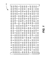
- LDPC code is specified by a parity check matrix (which is commonly referred to as an H matrix) having a very few number of “ones” per row.
- An example H matrix 100 is shown in FIG. 1 .
- the length of each codeword is equal to the number of columns in the H matrix 100 .
- each codeword is created such that the parity of each set of bits corresponding to the “ones” in a row is even.
- the number of rows corresponds to the number of parity checks that the codeword must satisfy. Therefore, if all errors in a received codeword are corrected by the decoder, all parity checks must be satisfied for the output codeword.
- Each received data bit from a channel has a probability value (e.g., a continuous analog value or a multi-bit resolution value after an analog-to-digital conversion) associated with the data bit.
- the associated data value identifies the probability of the bit being “1” or “0”.
- LDPC decoding is based on soft decoding of probabilities—i.e., probability values of bits are received in a pre-coded codeword, which codeword goes through multiple iterations of calculations based on the H matrix to arrive at enhanced probabilities. After a last iteration, a slicer determines if the original bit value was a “1” or a “0” based on a final enhanced probability associated with the bit.
- the two node functions in LDPC decoding equality constraint nodes and parity check nodes—perform probability calculations as described below.
- a given equality constraint node receives an initial intrinsic probability of each bit of a codeword together with a probability correction value from N parity check nodes (where N is the number of 1's in each column of the H matrix).
- the equality constraint node multiplies all the probabilities together and at each of the N connections, a new output probability value is determined, in which the new probability value is the product of all of the probabilities divided by the probability of that connection.
- the probability ratios of a bit e.g., P1/P0
- LLR log likelihood ratios
- a parity check node receives the output of M equality constraint nodes (where M is the number of 1's in each row of the H matrix), and performs a probability sum-product function. For example, if a parity check node connects to three equality constraint nodes A, B, C, then the output at connection A is given by: P B0 P C1 +P B1 P C0 eq. (1) and the output at connection B is given by: P A0 P C1 +P A1 P C0 eq. (2) and so on.
- conventional techniques include use of a hyperbolic tangent that directly operates on LLR values. Another technique for performing a parity check is through use of the min-sum function.
- the min-sum function is significantly less implementation intensive compared to the sum-product function, the min-sum function generally suffers from lower decoding gain.
- a modification to the min-sum algorithm i.e., the “min-sum with correction” algorithm—that results in a decoder having a similar decoding gain to an implementation of the sum-product function.
- the “min-sum with correction” algorithm is described in an article entitled “Reduced complexity decoding of LDPC codes,” by J. Cheng, et al., IEEE Transactions on Communication, vol. 53, no. 8, pp. 1288-1299, August 2005, which is incorporated by reference herein.
- An important feature of one implementation of an iterative decoder is the number of iterations that the iterative decoder can perform on an input codeword in a given amount of time as it relates to the bit error rate (BER) of the iterative decoder.
- BER bit error rate
- a higher number of iterations results in a better BER performance of an iterative decoder. Therefore, to maximize the performance of a single iterative decoder, it is generally preferred to have a given iterative decoder perform a higher number of iterations in a certain time interval—i.e., to go through a certain number of equality constraint and parity check nodes per unit time (which determines the BER performance of the iterative decoder).
- Another factor that affects the performance of a digital decoder is the resolution of probability messages at the inputs and between equality constraint nodes and parity check nodes. A higher resolution can potentially result in better performance of the decoder as probability calculations are performed more accurately and with a smaller error.
- an iterative decoder can perform in a time interval of each data codeword versus the power and complexity of the iterative decoder.
- a digital iterative decoder one can increase the clock frequency, increase the gate sizes, add more flip-flops between logic stages, adopt different implementation architectures, and/or run at higher supply voltage in order to get more iterations per codeword at cost of more power.
- this specification describes a technique to reduce the resolution of messages and, therefore, the logic complexity in a digital implementation of a “min-sum with correction” algorithm without any compromise in performance.
- an iterative decoder configured to implement a min-sum with correction algorithm is disclosed.
- the iterative decoder includes N parity check nodes coupled to M equality constraint nodes.
- the iterative decoder further includes a first parity check node configured to send an output to a first equality constraint node.
- the parity check node Responsive to a minimum magnitude of other M ⁇ 1 inputs to the first parity check node being lower than a pre-determined threshold, the parity check node sends the output having a same magnitude as that of the minimum magnitude of the other M ⁇ 1 inputs to the first parity check node. Responsive to the minimum magnitude of the other M ⁇ 1 inputs to the first parity check node being greater than the pre-determined threshold, the parity check node subtracts a correction factor in the form of p ⁇ 2 q from the minimum magnitude.
- Implementations can include one or more of the following features.
- the correction factor can be identified empirically.
- the output can have a resolution of 8 bits, and the correction factor can be 19.
- the correction factor in one example implementation of a decoder, can be in the form of one of the following: 9 ⁇ 2 1 , 2 4 , 5 ⁇ 2 2 , 11 ⁇ 2 1 , or 3 ⁇ 2 3 .
- the iterative decoder can be one of a low density parity check (LDPC) decoder, a Hamming decoder, or a Turbo decoder.
- LDPC low density parity check
- the iterative decoder can be compliant with IEEE 10G-BaseT standards, or other IEEE standards.
- FIG. 1 is a diagram of an H matrix.
- FIG. 2 illustrates one implementation of a method for selecting a correction factor for use in a decoder that implements a min-sum with correction algorithm.
- FIG. 3 is a block diagram of a decoding architecture for a decoder according to one implementation.
- FIG. 4 is a block diagram an iterative decoder including a first set of nodes and a second set of nodes according to one implementation.
- the present invention relates generally to data communications, and more particularly to error correction in data communications.
- the present invention is not intended to be limited to the implementations shown but is to be accorded the widest scope consistent with the principles and features described herein.
- a parity check node outputs the minimum magnitude of other M ⁇ 1 inputs (instead of performing a sum of products of all other M ⁇ 1 inputs). If the magnitude (of other M ⁇ 1 inputs) is lower than a pre-determined threshold, the parity check node outputs the same magnitude.
- a correction factor a fixed offset value (e.g., smaller than the threshold value)—is subtracted from the magnitude value (e.g., through the parity check node or other logic) before the magnitude value is sent from the parity check node.
- the sign of the parity output is the product of all other M ⁇ 1 inputs and not only the sign of the minimum input.
- the complexity of the decoder is mainly defined by resolution of internal messages—i.e., messages communicated between equality constraint nodes and parity check nodes.
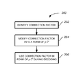
- FIG. 2 illustrates one implementation of a method 200 for selecting a correction factor for use in a decoder that implements a min-sum with correction algorithm.
- a correction factor is identified (step 202 ).
- a correction factor is identified for a decoder in a pre-determined signal-to-noise ratio (SNR) condition.
- the correction factor is determined empirically—e.g., from observation or experiment.
- a correction factor can be identified through other suitable techniques.
- the correction factor is modified into the form of p ⁇ 2 q that is closest to the ideal correction factor.
- p is an odd number and is as small as possible
- q is an integer and is as large as possible.
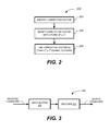
- FIG. 3 illustrates one example of a decoding architecture 300 suitable for implementing techniques described herein.
- the decoding architecture 300 can be a decoding architecture as described in U.S. patent application Ser. No. 11/676,946, entitled “Low Power Iterative Decoder Using Input Data Pipelining and Voltage Scaling”, filed on Feb. 20, 2007, the entire contents of which are incorporated by reference herein.
- the decoding architecture 300 includes an input buffer 302 , and a decoder 304 .
- the input buffer 302 is a memory that stores one or more codewords to be processed by the decoder 304 .
- the input buffer is a FIFO (First-In, First-Out) buffer.
- the decoder 304 is an iterative decoder.
- the decoder 304 can be a low density parity check (LDPC) decoder, a Hamming decoder, or a Turbo decoder.
- LDPC low density parity check
- the decoder 304 can be any other type of error correcting decoder that processes codewords in an iterative manner.
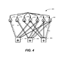
- FIG. 4 illustrates a block diagram of an iterative decoder 400 having a reduced complexity in accordance with one implementation.
- the iterative decoder 400 can be a low density parity check (LDPC) decoder, Hamming decoder, Turbo decoder, or the like.
- the iterative decoder 400 includes a first set of nodes 402 having N bits of resolution, and a second set of nodes 404 also having N bits of resolution.
- the first set of nodes 402 can be equality constraint nodes and the second set of nodes 404 can be parity check nodes.
- an LDPC decoder using a min-sum with correction algorithm can have few correction factors that result in an optimum performance for the decoder.
- the higher the value of q the smaller the decoder would be at the price of possible less decoding gain.
- Such a tradeoff can be directly used to implement LDPC decoders for short versus long reach channels where different SNR gains are required.
- the original 8 bits messaging can be reduced to 6 bits, if a correction factor of 16, 20 or 24 is used.
- the correction factors for new 6 bit messaging can be 4, 5 or 6.
- the resolution of the internal messages can be further reduced to 5 bits for correction factors of 16 (2 4 ) and 24 (3 ⁇ 2 3 ), while it would be limited to 6 bits if correction factor of 20 (5 ⁇ 2 2 ) is chosen.
Abstract
Description
PB0PC1+PB1PC0 eq. (1)
and the output at connection B is given by:
PA0PC1+PA1PC0 eq. (2)
and so on. Again, to avoid the use of complex multipliers, conventional techniques include use of a hyperbolic tangent that directly operates on LLR values. Another technique for performing a parity check is through use of the min-sum function. Although the min-sum function is significantly less implementation intensive compared to the sum-product function, the min-sum function generally suffers from lower decoding gain. However, a modification to the min-sum algorithm has been proposed—i.e., the “min-sum with correction” algorithm—that results in a decoder having a similar decoding gain to an implementation of the sum-product function. The “min-sum with correction” algorithm is described in an article entitled “Reduced complexity decoding of LDPC codes,” by J. Cheng, et al., IEEE Transactions on Communication, vol. 53, no. 8, pp. 1288-1299, August 2005, which is incorporated by reference herein.
Claims (12)
Priority Applications (1)
| Application Number | Priority Date | Filing Date | Title |
|---|---|---|---|
| US12/118,650 US8281210B1 (en) | 2006-07-07 | 2008-05-09 | Optimized correction factor for low-power min-sum low density parity check decoder (LDPC) |
Applications Claiming Priority (3)
| Application Number | Priority Date | Filing Date | Title |
|---|---|---|---|
| US81905606P | 2006-07-07 | 2006-07-07 | |
| US77517907A | 2007-07-10 | 2007-07-10 | |
| US12/118,650 US8281210B1 (en) | 2006-07-07 | 2008-05-09 | Optimized correction factor for low-power min-sum low density parity check decoder (LDPC) |
Related Parent Applications (1)
| Application Number | Title | Priority Date | Filing Date |
|---|---|---|---|
| US77517907A Continuation | 2006-07-07 | 2007-07-10 |
Publications (1)
| Publication Number | Publication Date |
|---|---|
| US8281210B1 true US8281210B1 (en) | 2012-10-02 |
Family
ID=46924885
Family Applications (1)
| Application Number | Title | Priority Date | Filing Date |
|---|---|---|---|
| US12/118,650 Active 2030-04-25 US8281210B1 (en) | 2006-07-07 | 2008-05-09 | Optimized correction factor for low-power min-sum low density parity check decoder (LDPC) |
Country Status (1)
| Country | Link |
|---|---|
| US (1) | US8281210B1 (en) |
Cited By (9)
| Publication number | Priority date | Publication date | Assignee | Title |
|---|---|---|---|---|
| US20170026055A1 (en) * | 2015-07-24 | 2017-01-26 | Tidal Systems, Inc. | Adaptive desaturation in min-sum decoding of ldpc codes |
| US20180159555A1 (en) * | 2016-12-01 | 2018-06-07 | Western Digital Technologies, Inc. | Configurable ecc decoder |
| US10141950B2 (en) | 2007-05-01 | 2018-11-27 | The Texas A&M University System | Low density parity check decoder |
| US10218384B2 (en) | 2016-12-01 | 2019-02-26 | Sandisk Technologies Llc | ECC decoder with multiple decoding modes |
| US20190312594A1 (en) * | 2019-06-21 | 2019-10-10 | Intel Corporation | Non-uniform iteration-dependent min-sum scaling factors for improved performance of spatially-coupled ldpc codes |
| US10565040B2 (en) | 2016-12-01 | 2020-02-18 | Western Digital Technologies, Inc. | ECC decoder with selective component disabling based on decoding message resolution |
| US10574274B2 (en) * | 2017-09-29 | 2020-02-25 | Nyquist Semiconductor Limited | Systems and methods for decoding error correcting codes |
| US11108407B1 (en) * | 2020-03-09 | 2021-08-31 | SK Hynix Inc. | Performance of a bit flipping (BF) decoder of an error correction system |
| US11251810B2 (en) * | 2020-01-30 | 2022-02-15 | Beijing Tenafe Electronic Technology Co., Ltd. | Low-density parity-check decoding with desaturation |
Citations (11)
| Publication number | Priority date | Publication date | Assignee | Title |
|---|---|---|---|---|
| US4295218A (en) * | 1979-06-25 | 1981-10-13 | Regents Of The University Of California | Error-correcting coding system |
| US5481614A (en) * | 1992-03-02 | 1996-01-02 | At&T Corp. | Method and apparatus for coding audio signals based on perceptual model |
| US5819212A (en) * | 1995-10-26 | 1998-10-06 | Sony Corporation | Voice encoding method and apparatus using modified discrete cosine transform |
| US6614858B1 (en) * | 2000-02-17 | 2003-09-02 | Agere Systems Inc. | Limiting range of extrinsic information for iterative decoding |
| US20070011586A1 (en) * | 2004-03-31 | 2007-01-11 | Belogolovy Andrey V | Multi-threshold reliability decoding of low-density parity check codes |
| US20080086670A1 (en) * | 2004-12-29 | 2008-04-10 | Krouk Evguenii A | Channel Estimation and Fixed Thresholds for Multi-Threshold Decoding of Low-Density Parity Check Codes |
| US20090222711A1 (en) * | 2004-03-31 | 2009-09-03 | Andrey Vladimirovich Belogolovy | Generalized Multi-Threshold Decoder for Low-Density Parity Check Codes |
| US20090222710A1 (en) * | 2008-02-29 | 2009-09-03 | Ara Patapoutian | Selectively applied hybrid min-sum approximation for constraint node updates of ldpc decoders |
| US20100174965A1 (en) * | 2009-01-07 | 2010-07-08 | Intel Corporation | Ldpc codes with small amount of wiring |
| US20110126078A1 (en) * | 2009-11-23 | 2011-05-26 | Yeong-Luh Ueng | Decoder and decoding method for low-density parity check codes constructed based on reed-solomon codes |
| US20110214039A1 (en) * | 2010-02-28 | 2011-09-01 | Steiner Avi | System and method for multi-dimensional decoding |
-
2008
- 2008-05-09 US US12/118,650 patent/US8281210B1/en active Active
Patent Citations (12)
| Publication number | Priority date | Publication date | Assignee | Title |
|---|---|---|---|---|
| US4295218A (en) * | 1979-06-25 | 1981-10-13 | Regents Of The University Of California | Error-correcting coding system |
| US5481614A (en) * | 1992-03-02 | 1996-01-02 | At&T Corp. | Method and apparatus for coding audio signals based on perceptual model |
| US5819212A (en) * | 1995-10-26 | 1998-10-06 | Sony Corporation | Voice encoding method and apparatus using modified discrete cosine transform |
| US6614858B1 (en) * | 2000-02-17 | 2003-09-02 | Agere Systems Inc. | Limiting range of extrinsic information for iterative decoding |
| US20070011586A1 (en) * | 2004-03-31 | 2007-01-11 | Belogolovy Andrey V | Multi-threshold reliability decoding of low-density parity check codes |
| US20090222711A1 (en) * | 2004-03-31 | 2009-09-03 | Andrey Vladimirovich Belogolovy | Generalized Multi-Threshold Decoder for Low-Density Parity Check Codes |
| US7716561B2 (en) * | 2004-03-31 | 2010-05-11 | Intel Corporation | Multi-threshold reliability decoding of low-density parity check codes |
| US20080086670A1 (en) * | 2004-12-29 | 2008-04-10 | Krouk Evguenii A | Channel Estimation and Fixed Thresholds for Multi-Threshold Decoding of Low-Density Parity Check Codes |
| US20090222710A1 (en) * | 2008-02-29 | 2009-09-03 | Ara Patapoutian | Selectively applied hybrid min-sum approximation for constraint node updates of ldpc decoders |
| US20100174965A1 (en) * | 2009-01-07 | 2010-07-08 | Intel Corporation | Ldpc codes with small amount of wiring |
| US20110126078A1 (en) * | 2009-11-23 | 2011-05-26 | Yeong-Luh Ueng | Decoder and decoding method for low-density parity check codes constructed based on reed-solomon codes |
| US20110214039A1 (en) * | 2010-02-28 | 2011-09-01 | Steiner Avi | System and method for multi-dimensional decoding |
Non-Patent Citations (1)
| Title |
|---|
| Chen, J., et al., "Reduced-Complexity Decoding of LDPC Codes," (2005) IEEE Transactions on Communications, 53(8):1288-1299. |
Cited By (17)
| Publication number | Priority date | Publication date | Assignee | Title |
|---|---|---|---|---|
| US11728828B2 (en) | 2007-05-01 | 2023-08-15 | The Texas A&M University System | Low density parity check decoder |
| US10141950B2 (en) | 2007-05-01 | 2018-11-27 | The Texas A&M University System | Low density parity check decoder |
| US11368168B2 (en) | 2007-05-01 | 2022-06-21 | The Texas A&M University System | Low density parity check decoder |
| US10951235B2 (en) | 2007-05-01 | 2021-03-16 | The Texas A&M University System | Low density parity check decoder |
| US10615823B2 (en) | 2007-05-01 | 2020-04-07 | The Texas A&M University System | Low density parity check decoder |
| US20170026055A1 (en) * | 2015-07-24 | 2017-01-26 | Tidal Systems, Inc. | Adaptive desaturation in min-sum decoding of ldpc codes |
| US9755666B2 (en) * | 2015-07-24 | 2017-09-05 | Tidal Systems, Inc. | Adaptive desaturation in min-sum decoding of LDPC codes |
| US10177786B2 (en) | 2015-07-24 | 2019-01-08 | Tidal Systems, Inc. | Adaptive desaturation in min-sum decoding of LDPD codes |
| US10565040B2 (en) | 2016-12-01 | 2020-02-18 | Western Digital Technologies, Inc. | ECC decoder with selective component disabling based on decoding message resolution |
| US10530393B2 (en) * | 2016-12-01 | 2020-01-07 | Western Digital Technologies, Inc. | Configurable ECC decoder |
| US10218384B2 (en) | 2016-12-01 | 2019-02-26 | Sandisk Technologies Llc | ECC decoder with multiple decoding modes |
| US20180159555A1 (en) * | 2016-12-01 | 2018-06-07 | Western Digital Technologies, Inc. | Configurable ecc decoder |
| US10574274B2 (en) * | 2017-09-29 | 2020-02-25 | Nyquist Semiconductor Limited | Systems and methods for decoding error correcting codes |
| US20190312594A1 (en) * | 2019-06-21 | 2019-10-10 | Intel Corporation | Non-uniform iteration-dependent min-sum scaling factors for improved performance of spatially-coupled ldpc codes |
| US11159175B2 (en) * | 2019-06-21 | 2021-10-26 | Intel Corporation | Non-uniform iteration-dependent min-sum scaling factors for improved performance of spatially-coupled LDPC codes |
| US11251810B2 (en) * | 2020-01-30 | 2022-02-15 | Beijing Tenafe Electronic Technology Co., Ltd. | Low-density parity-check decoding with desaturation |
| US11108407B1 (en) * | 2020-03-09 | 2021-08-31 | SK Hynix Inc. | Performance of a bit flipping (BF) decoder of an error correction system |
Similar Documents
| Publication | Publication Date | Title |
|---|---|---|
| US8281210B1 (en) | Optimized correction factor for low-power min-sum low density parity check decoder (LDPC) | |
| JP4595650B2 (en) | Decoding device and decoding method | |
| US7577891B2 (en) | Method and apparatus for extending decoding time in an iterative decoder using input codeword pipelining | |
| US7395487B2 (en) | Common circuitry supporting both bit node and check node processing in LDPC (Low Density Parity Check) decoder | |
| EP1442527B1 (en) | Node processors for use in parity check decoders | |
| US7539920B2 (en) | LDPC decoding apparatus and method with low computational complexity algorithm | |
| US7219288B2 (en) | Running minimum message passing LDPC decoding | |
| US20080294970A1 (en) | Method for implementing stochastic equality nodes | |
| US7853854B2 (en) | Iterative decoding of a frame of data encoded using a block coding algorithm | |
| US20050262421A1 (en) | Efficient front end memory arrangement to support parallel bit node and check node processing in LDPC (Low Density Parity Check) decoders | |
| US20060085720A1 (en) | Message passing memory and barrel shifter arrangement in LDPC (Low Density Parity Check) decoder supporting multiple LDPC codes | |
| US20050262424A1 (en) | Efficient design to implement LDPC (Low Density Parity Check) decoder | |
| JP4293172B2 (en) | Decoding device and decoding method | |
| JP4622654B2 (en) | Decoding device and decoding method | |
| US20060107193A1 (en) | Method and apparatus for efficiently decoding low density parity check code | |
| US20090106620A1 (en) | Decoding apparatus, decoding method and program | |
| US20040153942A1 (en) | Soft input soft output decoder for turbo codes | |
| WO2008034254A1 (en) | Stochastic decoding of ldpc codes | |
| CN101154948A (en) | Methods and apparatus for low-density parity check decoding using hardware-sharing and serial sum-product architecture | |
| US8234536B1 (en) | Iterative decoder using input data pipelining and time-interleaved processing | |
| US20050246618A1 (en) | Efficient design to implement min**/min**- or max**/max**- functions in LDPC (low density parity check) decoders | |
| CN113300719B (en) | Multi-system irregular repeat accumulate code parallel coding device and method | |
| JP4729964B2 (en) | Decoding device and decoding method | |
| US7640482B2 (en) | Block processing in a block decoding device | |
| Mahdy et al. | Design and implementation of parallel branches for concatenated BCH and LDPC coding on FPGA |
Legal Events
| Date | Code | Title | Description |
|---|---|---|---|
| AS | Assignment |
Owner name: AQUANTIA CORPORATION, CALIFORNIA Free format text: ASSIGNMENT OF ASSIGNORS INTEREST;ASSIGNORS:SHIRANI, RAMIN;FARJADRAD, RAMIN;REEL/FRAME:020943/0018 Effective date: 20070927 |
|
| STCF | Information on status: patent grant |
Free format text: PATENTED CASE |
|
| FPAY | Fee payment |
Year of fee payment: 4 |
|
| AS | Assignment |
Owner name: CAVIUM INTERNATIONAL, CAYMAN ISLANDS Free format text: ASSIGNMENT OF ASSIGNORS INTEREST;ASSIGNOR:AQUANTIA CORPORATION;REEL/FRAME:051945/0520 Effective date: 20191231 |
|
| FEPP | Fee payment procedure |
Free format text: ENTITY STATUS SET TO UNDISCOUNTED (ORIGINAL EVENT CODE: BIG.); ENTITY STATUS OF PATENT OWNER: LARGE ENTITY |
|
| MAFP | Maintenance fee payment |
Free format text: PAYMENT OF MAINTENANCE FEE, 8TH YEAR, LARGE ENTITY (ORIGINAL EVENT CODE: M1552); ENTITY STATUS OF PATENT OWNER: LARGE ENTITY Year of fee payment: 8 |
|
| AS | Assignment |
Owner name: MARVELL ASIA PTE, LTD., SINGAPORE Free format text: ASSIGNMENT OF ASSIGNORS INTEREST;ASSIGNOR:CAVIUM INTERNATIONAL;REEL/FRAME:053179/0320 Effective date: 20191231 |
|
| MAFP | Maintenance fee payment |
Free format text: PAYMENT OF MAINTENANCE FEE, 12TH YEAR, LARGE ENTITY (ORIGINAL EVENT CODE: M1553); ENTITY STATUS OF PATENT OWNER: LARGE ENTITY Year of fee payment: 12 |