US8331436B2 - Expert system and method for elastic encoding of video according to regions of interest - Google Patents

Expert system and method for elastic encoding of video according to regions of interest Download PDF

Info

Publication number
US8331436B2
US8331436B2 US12/226,957 US22695707A US8331436B2 US 8331436 B2 US8331436 B2 US 8331436B2 US 22695707 A US22695707 A US 22695707A US 8331436 B2 US8331436 B2 US 8331436B2
Authority
US
United States
Prior art keywords
region
interest
video feed
bits
quality
Prior art date
Legal status (The legal status is an assumption and is not a legal conclusion. Google has not performed a legal analysis and makes no representation as to the accuracy of the status listed.)
Expired - Fee Related, expires
Application number
US12/226,957
Other versions
US20090232203A1 (en
Inventor
Nuggehally Sampath Jayant
Sira P. Rao
Current Assignee (The listed assignees may be inaccurate. Google has not performed a legal analysis and makes no representation or warranty as to the accuracy of the list.)
Omet SRL
Georgia Tech Research Corp
Original Assignee
Georgia Tech Research Corp
Priority date (The priority date is an assumption and is not a legal conclusion. Google has not performed a legal analysis and makes no representation as to the accuracy of the date listed.)
Filing date
Publication date
Application filed by Georgia Tech Research Corp filed Critical Georgia Tech Research Corp
Priority to US12/226,957 priority Critical patent/US8331436B2/en
Assigned to OMET S.R.I. reassignment OMET S.R.I. ASSIGNMENT OF ASSIGNORS INTEREST (SEE DOCUMENT FOR DETAILS). Assignors: BARTESAGHI, ANGELO
Assigned to GEORGIA TECH RESEARCH CORPORATION reassignment GEORGIA TECH RESEARCH CORPORATION ASSIGNMENT OF ASSIGNORS INTEREST (SEE DOCUMENT FOR DETAILS). Assignors: JAYANT, NUGGENHALLY SAMPATH, RAO, SIRA P.
Publication of US20090232203A1 publication Critical patent/US20090232203A1/en
Application granted granted Critical
Publication of US8331436B2 publication Critical patent/US8331436B2/en
Expired - Fee Related legal-status Critical Current
Adjusted expiration legal-status Critical

Links

Images

Classifications

    • HELECTRICITY
    • H04ELECTRIC COMMUNICATION TECHNIQUE
    • H04NPICTORIAL COMMUNICATION, e.g. TELEVISION
    • H04N19/00Methods or arrangements for coding, decoding, compressing or decompressing digital video signals
    • H04N19/10Methods or arrangements for coding, decoding, compressing or decompressing digital video signals using adaptive coding
    • H04N19/102Methods or arrangements for coding, decoding, compressing or decompressing digital video signals using adaptive coding characterised by the element, parameter or selection affected or controlled by the adaptive coding
    • H04N19/115Selection of the code volume for a coding unit prior to coding
    • HELECTRICITY
    • H04ELECTRIC COMMUNICATION TECHNIQUE
    • H04NPICTORIAL COMMUNICATION, e.g. TELEVISION
    • H04N19/00Methods or arrangements for coding, decoding, compressing or decompressing digital video signals
    • H04N19/10Methods or arrangements for coding, decoding, compressing or decompressing digital video signals using adaptive coding
    • H04N19/134Methods or arrangements for coding, decoding, compressing or decompressing digital video signals using adaptive coding characterised by the element, parameter or criterion affecting or controlling the adaptive coding
    • H04N19/164Feedback from the receiver or from the transmission channel
    • HELECTRICITY
    • H04ELECTRIC COMMUNICATION TECHNIQUE
    • H04NPICTORIAL COMMUNICATION, e.g. TELEVISION
    • H04N19/00Methods or arrangements for coding, decoding, compressing or decompressing digital video signals
    • H04N19/10Methods or arrangements for coding, decoding, compressing or decompressing digital video signals using adaptive coding
    • H04N19/169Methods or arrangements for coding, decoding, compressing or decompressing digital video signals using adaptive coding characterised by the coding unit, i.e. the structural portion or semantic portion of the video signal being the object or the subject of the adaptive coding
    • H04N19/17Methods or arrangements for coding, decoding, compressing or decompressing digital video signals using adaptive coding characterised by the coding unit, i.e. the structural portion or semantic portion of the video signal being the object or the subject of the adaptive coding the unit being an image region, e.g. an object

Definitions

  • the present invention relates to encoding video at subjectively acceptable quality over limited and variable bit-rate networks using a region-of-interest framework. More generally described, the present invention provides an elastic expert system and method for assigning bit-rates to regions of encoded video based on domain and application specific awareness.
  • Remote assessment of distressed patients using telemedicine systems is likely to be a critical and pervasive component of future healthcare systems. Depending upon geography and economics, remote assessment is likely to occur over both wired and wireless networks and, thus, over a broad spectrum of transmission bandwidths ranging from very low to very high. Available transmission bandwidth can place a significant constraint on the overall compression ratio of the video, but for diagnostic purposes—i.e., for clinical or functional acceptability—it is essential that the compression process causes no tangible loss of detail and introduces no noticeable artifacts which could lead to misinterpretation. Accordingly, tele-medicine or tele-health systems that have the potential to deal with such bandwidth limitations while providing visually acceptable video will provide specialists with significantly more information for assessment, diagnosis, and management than will systems without that capability.
  • Region-of-interest (ROI) based video processing is useful for achieving optimal balance in the quality-bandwidth trade-off.
  • Conventional ROI coding typically divides compressed video into two regions—the ROI and background (BKGRND) and assigns varying compression to each region.
  • ROI video coding provides higher quality in the ROI, but poorer quality in the BKGRND, for a given total bit-rate (TBR).
  • TBR total bit-rate
  • the BKGRND is dropped altogether.
  • An extension of the ROI concept is the extended region-of-interest (EROI), which consists of an intermediate region between the ROI and BKGRND.
  • the EROI enhances the elasticity of an ROI based video coding scheme by allowing for a more perceptually pleasing degradation in quality from the ROI.
  • ML mathematical losslessness
  • PL video coding incorporates human visual system (HVS) factors into a distortion measure to determine the optimum value of a parameter that satisfies a given threshold. When this threshold equals the just-noticeable-difference (JND), the result is PL encoded video (when compared with the original). Because of the many solutions for PL video coding, most commercial video coders incorporate different levels of empirical perceptual tuning.
  • HVS human visual system
  • the definition of PL must be different from the HVS based definition of PL.
  • the latter is based on masking properties of the HVS, which may not be consistent with the details a medical expert wants to see in a video. That is, a HVS definition of PL applied to a video will add distortion to regions that the HVS considers as unimportant, but these might be critical diagnostic regions for the medical expert.
  • the definition of PL referred to herein is considered to be a level of video that is visually perfect i.e., free of any artifacts.
  • the elastic expert system can be used to allocate bits efficiently according to application domain requirements and network resources.
  • the network can be any type of transmission medium, including, but not limited to, a wired network, wireless network, and mobile network. Regardless of the type of network, the elastic expert system is capable of observing the bits available for the network (i.e., bandwidth) and, based on this evaluation, can allocate a portion of the total bits available to a region-of-interest by examining the application domain requirements.
  • the application domain requirements may comprise bit-rate values representing perceptual losslessness (PL), functional (or diagnostic) losslessness (FL or PL), and best effort (BE). These values can be gathered using a functional hierarchy assessment.
  • the functional hierarchy assessment may comprise playing videos to an identified group of subjects to evaluate functional or diagnostic quality of video. The results of the functional hierarchy assessment can then be used to determine values for PL, FL, and BE.
  • the elastic expert system may formulate states to efficiently allocate bit-rates between a region-of-interest and background in an encoded video.
  • states To enter a state, the total bits available for an encoded video are compared to the bits required for the background and region-of-interest for that state. If the state can be entered, then the elastic expert system will set the bits for the background and the region-of-interest according to that state. If the state cannot be entered, the elastic expert system will evaluate the next state.
  • the states are numbered sequentially (e.g., 1 to 10) according to decreasing priority. This is based on the premise that the ROI quality should be at least the same as or better than the BKGRND quality.
  • FIG. 1 illustrates a representative operating environment for the elastic expert system, according to an exemplary embodiment.
  • FIG. 2 illustrates a method for implementing the elastic expert system, according to an exemplary embodiment.
  • FIGS. 3A , 3 B, and 3 C illustrate methods for encoding video feed, according to several exemplary embodiments.
  • FIG. 4 illustrates a method for implementing a functional hierarchy assessment, according to an exemplary embodiment.
  • FIG. 5 illustrates a method for determining states in the elastic expert system, according to an exemplary embodiment.
  • FIG. 6 illustrates a method for converting allocated bits to quantization parameters, according to an exemplary embodiment.
  • FIG. 7 illustrates a method for implementing the elastic expert system, according to another exemplary embodiment.
  • FIG. 8 illustrates a method for implementing the elastic expert system, according to an exemplary embodiment.
  • the inventive elastic expert system can be used to deliver diagnostically acceptable video quality over limited and variable bit-rate networks using a region-of-interest framework.
  • the design of the system consists of quantification of video quality through tests on training videos with a representative audience, typically subject-matter experts, such as medical experts for tele-medicine videos, incorporation of the above information into the video encoder through the use of encoder states, and fine tuning of these states based on built-in quality criteria.
  • the elastic expert system may be used in any situation where it is desirable to encode a region-of-interest for functional assessment including, but not limited to tele-health and surveillance applications.
  • FIG. 1 illustrates an exemplary operating environment 100 for the elastic expert system 110 .
  • the elastic expert system 110 is preferably situated between a video feed 105 and network 120 .
  • the elastic expert system 110 communicates video to the network 120 through communication link 115 , whereby the network 120 sends the video to a decoder 130 and display device 135 through communication link 125 .
  • the network 120 , and communication links 115 , 125 may comprise any type of transmission medium, including, but not limited to, wired local networks, such as local area networks; wireless networks, such as the Internet; and mobile or cellular networks.
  • the elastic expert system 110 considers the network resources available for the network 120 and communication links 115 , 125 (collectively, the network resources), but is unconcerned with the type of network that the resources are associated with.
  • FIG. 2 illustrates a method for implementing the elastic expert system 110 , according to an exemplary embodiment.
  • the elastic expert system can be implemented in software, as is understood by one of ordinary skill in the art. Further, many modifications can be made to the elastic expert system 110 without departing from the scope and spirit of the invention.
  • the elastic expert system 110 has elasticity in terms of three attributes (as will be discussed in detail hereinbelow): (1) domain application requirements; (2) network resources; and (3) the window geometry of the region-of-interest.
  • the elastic expert system 110 receives uncompressed video input from a video source, such as a camera focused on a patient.
  • the expert system receives application domain requirements for the video. These application domain requirements may be static (off-line) or dynamic (on-line). In an exemplary embodiment, the elastic expert system 110 receives static domain requirements.
  • the domain requirements relate to four levels of quality: mathematical losslessness (ML) (i.e., there is no loss of any digital information); perceptual losslessness (PL) (i.e., there is no visual distinguish-ability with the original video); diagnostic or functional losslessness (DL or FL) (i.e., there may be visually perceivable artifacts, but they do not compromise visual diagnostic or functional assessment); and best effort (BE) (i.e., where the video quality is not distracting or annoying).
  • ML mathematical losslessness
  • PL perceptual losslessness
  • DL or FL diagnostic or functional losslessness
  • BE best effort
  • the elastic expert system 110 observes the network resources available on the network 120 and communication links 115 , 125 . That is, in a preferred, yet exemplary embodiment, the elastic expert system 110 observes the bandwidth (i.e., total bits available for transmission) available on the network 120 (including communication links 115 , 125 ) at step 215 .
  • the available network resources may be dynamic (on-line) or static (off-line).
  • the network resources are dynamic and therefore may change over time. Accordingly, the elastic expert system continuously or periodically re-observes the network resources available.
  • the elastic expert system 110 determines a state for encoding the ROI and BKGRND (and EROI, if utilized) at step 220 (as discussed further with reference to FIG. 5 ). Then, at step 225 , the various regions, such as the ROI and BKGRND, are encoded according to the state determined at step 220 (as discussed further with reference to FIG. 8 ).
  • FIGS. 3A , 3 B, and 3 C illustrate several ways to encode a video feed using ROIs, according to an exemplary embodiment of the elastic expert system 110 .
  • Conventional methods for implementing ROIs comprise automatic and semi-automatic ROIs. Automatic methods perform the task of determination and tracking of the ROI, whereas semi-automatic methods leave the determination as a periodic task for the user to perform, and track a complex ROI contour representing the ROI boundary between these intervals. These methods are characterized by their complexity, but they lack a commensurate performance improvement. Hence, there is a motivation to perform tracking in a more simple but logical manner.
  • a video image 300 is encoded by utilizing conventional ROI 305 , EROI 310 , and BKGRND 315 .
  • EROI 310 By utilizing an EROI 310 , between the ROI 305 and BKGRND 315 , the bit rate allocation between each region is less dramatic because the bit rate allocation is gradually stepped down in each region.
  • the video image 300 is encoded using an ROI 305 and BKGRND 315 only.
  • this ROI 305 may be a preset size and placed in the middle of the image 300 .
  • additional elasticity is added to the expert system by allowing the size of the ROI to be assigned variable sizes, such as 1 ⁇ 4, 1/9, and 1/16 of the video image size, and may be adjustable between each size. It is proposed to have simple templates for the ROI, with the size and shape of this template coming from among a small set of acceptable choices (e.g. elliptical ROI, 1 ⁇ 4 the size of the image). The user may specify the template, and its center location.
  • the tracking algorithm determines the center location of the ROI template from frame to frame through a simple methodology based on color and motion information. For example, a new center location may be determined based on the estimated average horizontal and vertical displacements to the ROI template, which can be obtained using motion vectors.
  • FIG. 3C illustrates a method for encoding the video image 300 , where the ROI 305 rotates around the video image 300 at a preset sampling frequency.
  • This particular exemplary embodiment may be particularly applicable for the monitoring of surveillance video.
  • the ROI is depicted as rotating in a clockwise fashion, starting with the right hand corner at ROI 305 A.
  • the BKGRND fills the other areas of the video image 300 .
  • the ROI 305 A-D rotates around the screen in a clockwise fashion, covering BKGRND at respective portions. In this way, if the ROI 305 is rotated fast enough, each block of the screen will change from BKGRND to ROI quickly enough so that the actual region of interest in the video scene, even if not known apriori, will be captured with an adequate sampling frequency.
  • the elastic expert system 110 encodes the video feed 105 according to four levels of quality: mathematical losslessness (ML) (i.e., there is no loss of any digital information); perceptual losslessness (PL) (i.e., there is no visual distinguish-ability with the original video); functional losslessness (FL) (i.e., there may be visually perceivable artifacts, but they do not compromise functional assessment); and best effort (BE) (i.e., where the video quality is not distracting or annoying).
  • ML mathematical losslessness
  • PL perceptual losslessness
  • FL functional losslessness
  • BE best effort
  • ML is not required to be determined from the functional hierarchy assessment, because mathematical losslessness (ML) is a mathematically deterministic video quality level (unlike PL, FL, and BE), obtained when no quantization based compression is applied).
  • ML is a mathematically deterministic video quality level (unlike PL, FL, and BE), obtained when no quantization based compression is applied).
  • the application domain requirements for the elastic expert system 110 can be set.
  • FIG. 4 illustrates a method for implementing a functional hierarchy assessment, according to an exemplary embodiment.
  • subjects are identified for the functional hierarchy assessment. If the purpose of the elastic expert system 110 is to be utilized in a tele-health or tele-medicine environment, then physician experts would be identified and selected as the test subjects.
  • a video with uniform spatial quality is played for the subjects at step 410 .
  • the subjects are asked to give a functional assessment of the features and perceptual losslessness of the video.
  • the subjects may be asked to: (at step 415 A) identify identifiable features in the video; (at step 415 B) quantify the video quality based on whether a diagnostic or functional assessment could be made from the video; (at step 415 C) qualify whether the video appears to be perceptually perfect; and (at step 415 D) make a note of any artifacts they see in the video.
  • the compression rate of the video is randomly adjusted and the functional assessment at steps 410 and 415 is repeated. This cycle continues until a significant number of compression rates have been analyzed.
  • the average of the results can be taken at step 425 to determine PL, FL, and BE. Specifically, If TBR_FLi represents the TBR required for FL for feature i averaged over several experts and TBR_PL and TBR_BE represents the TBR required for PL and BE, respectively, also averaged over several experts, then the corresponding bits per pixel (bpp) required for each losslessness can be expressed as:
  • bpp_FLi TBR_FLi FR_RATE ⁇ FR_SIZE
  • bpp_PL TBR_PL FR_RATE ⁇ FR_SIZE
  • bpp_BE TBR_BE FR_RATE ⁇ FR_SIZE
  • FR_RATE the frame rate (in frames per second)
  • FR_SIZE the spatial resolution of the training videos (assuming one fixed value).
  • doctors could be used as subjects for the functional hierarchy assessment.
  • a set of training videos are played for the doctors at a variety of total bit rates (TBR) and uniform spatial quality.
  • TBR total bit rates
  • the doctors are then asked to identify maximum levels of compression that can be applied while retaining certain levels of quality.
  • the compressed training videos are presented in random order to the doctors and they complete an evaluation whose format is shown in Table 1, which in this example is specific to pediatric respiratory distress.
  • each doctor evaluates each of the videos according to the evaluation template shown, where the feature sets identified in this example stand for a rib retraction (RR), oral cyanosis (OC), and work of breathing (WB).
  • Each sample number represents a video at a particular total bit rate (TBR).
  • the physician expert lists whichever features he/she can identify in the video at that particular bit-rate.
  • the remaining three columns represent the quantification of the video quality information.
  • the four options relate to the quality of the video for clinical (i.e., functional) assessment of each feature set: 1—No, 2—Maybe Not, 3—Likely, 4 —Yes.
  • the lowest TBR at which the evaluation is 4 represents the threshold FL for the particular feature.
  • the lowest TBR at which “PL?” is ‘Yes’ represents the PL threshold for the particular video.
  • the expert identifies any annoying or distracting artifacts in the video. This information can be used to obtain the threshold for BE for the particular video. It should be noted that the above table represents one video evaluated by one particular expert, whereas the complete test set consists of several videos evaluated by several physician experts.
  • the elastic expert system 110 is made adaptive to network conditions through the notion of an encoder state.
  • An encoder state is defined by a pair of levels, one corresponding to the ROI, and the other corresponding to the BKGRND.
  • the notion of an encoder state also helps the encoder use the information on application domain requirements and map them to the ROI and BKGRND regions in the video.
  • the complete state table for the encoder is shown in Table 2.
  • the states are numbered 1 to 10 according to decreasing priority, based on the premise that the ROI quality should be at least the same as or better than the BKGRND quality.
  • state 2 represents ML quality ROI and PL quality BKGRND
  • state 8 represents FL quality ROI and FL quality BKGRND.
  • ROI quality will not be of a functional-lossless level
  • TBR the entire frame quality can be of a mathematical-lossless level.
  • the design is expected to have high value because of elastic associations between different levels of losslessness and different regions in the scene. For example, in narrowband environments, the design can achieve FL ROI quality, whereas in broadband environments, the design can achieve ML ROI and PL BKGRND qualities.
  • a group of pictures (GOP)-level bit allocation algorithm is utilized, based on nominal bpp values for PL, FL, and BE quality levels. State determination is done at the GOP level in order to average over I, P, and B frames.
  • ROI_SIZE is the average size of the ROI for the current GOP, and may be a window of standard shape and size around the feature(s).
  • N_GOP denotes the number of frames in GOP. Similar expressions hold for the nominal number of bits required for other quality levels for the ROI and BKGRND.
  • FIG. 5 illustrates a method for determining states in the elastic expert system 110 , according to an exemplary embodiment.
  • the encoder tries to occupy the highest priority state given the current TBR.
  • the elastic expert system 110 determines if enough bits are present for it to enter state 1. Specifically, if R denotes the target number of bits in a GOP, the encoder checks if it can occupy state 1, governed by the condition: R>R_ROI_ML+R_BKGRND_ML (i.e., are the total bits available greater than those necessary to have a mathematically lossless region-of-interest and background)? If so, the elastic expert system 110 occupies state 1 at step 510 A.
  • state 2 is governed by the condition: R>R_ROI_ML+R_BKGRND_PL (i.e., are the total bits available greater than those necessary to have a mathematically lossless region-of-interest and perceptually lossless background)? If yes, then state 2 is entered. If no, then the elastic expert system 110 continues until it occupies one of the ten possible exemplary states, as summarized in Table 2 and FIG. 5 .
  • R_ROI and R_BKGRND denote the target number of bits in a GOP for the ROI and BKGRND, respectively. If the encoder determines that state 9 is the current GOP state, the BKGRND gets assigned R_BKGRND_BE bits, and the ROI gets assigned at least R_BKGRND_FL bits. The only exception is state 10, where all the bits are allocated to the ROI.
  • the encoder occupies a particular state, which is the highest priority under the given conditions.
  • VBR variable bit rate
  • the encoder will likely transition to a new state at the beginning of a new GOP.
  • the encoder may move to a higher priority state or a lower priority state.
  • the elastic system achieves its two intended goals: (a) user-specified quality through incorporation of user inputs at the beginning of the design process itself, and (b) robustness to variability and limitations in channel TBR.
  • the states of the elastic expert system 110 may be periodically changed or shifted to increase the visual perception of the ROI.
  • the average bpp value over the features is chosen as the nominal value. Accordingly, the ROI may not be of FL quality even if its current state indicates that it should be so.
  • PL and BE are subjective notions of quality, these functional assessments may vary from viewer to viewer. Therefore, a quality level for the ROI as indicated by a particular state might not indeed be achieved as far as the current viewer of the video is concerned.
  • the elastic expert system 110 allocates more bits to the ROI whenever such a condition is detected. This allocation is done by a state transition from the current state to the next lower priority state in the same row. For example, suppose the encoder transitions from state 6 to state 7:
  • R_BKGRND ⁇ R_BKGRND ⁇ _FL
  • R_ROI ⁇ R - R_BKGRND STATE ⁇ ⁇ 7 :
  • R_BKGRND ⁇ R_BKGRND ⁇ _BE
  • R_ROI ⁇ R - R_BKGRND
  • R_ROI is higher in state 7 than in state 6. Transitions are not allowed to states in lower rows because the ROI quality level changes across rows. Instead, in states 4, 7, and 9, where the encoder is at the far end of a row (i.e., with BE quality BKGRND), R_ROI is increased by a parameter update i.e., by simply reducing R_BKGRND to a new, lower value R_BKGRND_BE_MIN, compared to R_BKGRND_BE.
  • a manual trigger may be used to indicate that video quality within the ROI is unsatisfactory. That is, a remote viewer may send an indication through the network that the state of the elastic expert system 110 needs to be shifted. This option is straightforward, yet cumbersome. Thus, an automatic trigger is preferred.
  • An automatic trigger may be used to indicate that video quality within the ROI is unsatisfactory.
  • Various quality metrics including a PSNR-difference approach between the ROI and BKGRND, a constant ROI PSNR approach, are options to automatically trigger a state transition or parameter update.
  • the bits can be related to the quantization parameter (Q) to perform encoding of the video. Accordingly, as illustrated at step 610 of FIG. 6 , Lagrangian optimization leads to the following expression for the ROI Q in one exemplary embodiment:
  • the subscript i represents the macroblock (MB) number
  • the superscript f represents the frame number
  • B T,ROI f is the target number of bits for the ROI
  • ⁇ T,ROI f is the variance of the i th MB of the ROI
  • ⁇ T,ROI f is the distortion weight for the ROI MB
  • A is the number of pixels in a MB
  • N ROI is the number of MBs in the ROI
  • C is the overhead rate
  • K is a constant.
  • B f T,ROI provides an additional degree of freedom over distortion weights to control ROI quality. Note that this is only dependent on the bits allocated to the ROI (B f T,ROI ) at step 610 , and the distortion weights for the ROI.
  • Similar processes are performed at steps 605 and 615 to determine the quantization parameters for the EROI and BKGRND regions of the frame.
  • a temporal approach may be used wherein the BKGRND is encoded less often than the ROI.
  • the ROI may need to be transmitted at the highest frame rate e.g. 30 frames per second (fps).
  • the BKGRND may not be needed that often, and hence may be transmitted at a sub-sampled rate (e.g., 5 fps). Utilizing this approach therefore offers significant savings in bits.
  • FIG. 7 illustrates another exemplary embodiment of the elastic expert system 110 .
  • the network resources 710 are evaluated to determine a target number of bits available for the entire frame (B T f ), where the superscript f represents the frame number.
  • the elastic expert system 110 determines the regional bit allocation by incorporating size 720 A and motion features 720 B as follows:
  • the S parameters are the normalized region size parameters
  • the M parameters are the normalized region activity descriptors—obtained from the motion vectors (MV) of each region.
  • S ROI represents the normalized size of the ROI in the video frame, and is calculated as the ratio of the number of ROI macroblocks in the video frame (N ROI ) to the total number of macroblocks in the video frame (N).
  • M ROI represents the normalized motion activity in the ROI, and is calculated as the ratio of the sum of all motion vectors corresponding to ROI macroblocks to the sum of all motion vectors of all macroblocks in the video frame.
  • perceptual features 720 C may also be used. These perceptual weights are used in this exemplary embodiment to achieve bit transfer between regions as,
  • FIG. 8 illustrates yet another exemplary method for implementing the elastic expert system 110 (according to any exemplary embodiment).
  • video input V in is fed to an encoder at step 805 .
  • This encoder performs uniform encoding of the entire frame at a bit rate of bpp BKGRND bpp (according to the bits allocated to the BKGRND), and this results in the base bitstream (B 1 ) at step 820 .
  • This base bitstream is then decoded to produce V base at step 810 , which is then subtracted from V in to result in the “error” video input, V diff .
  • V diff is then encoded using a ROI only encoder which encodes only the ROI of the input at a bit rate of bpp ROI ⁇ bpp BKGRND (according to the bits allocated to the ROI and BKGRND), resulting in the enhanced ROI bitstream (B 2 ) at step 825 .
  • a ROI only encoder which encodes only the ROI of the input at a bit rate of bpp ROI ⁇ bpp BKGRND (according to the bits allocated to the ROI and BKGRND), resulting in the enhanced ROI bitstream (B 2 ) at step 825 .

Abstract

An elastic expert system for allocating bits according to application domain requirements and network resources. The elastic expert system observes the network resources and determines a state for allocating bits, the state relating to the application domain requirements. The elastic expert system can then allocate bits to a region-of-interest based on the determined state. The elastic expert system also can allocate bits to a background region and an extended region of interest.

Description

RELATED PRIORITY APPLICATION
This application is a National Stage patent application filed under 35 §317 of International Patent Application No. PCT/US2007/010579, filed May 1, 2007, which designated the United States of America, and which claims priority to U.S. Provisional Patent Application No. 60/769,480, filed May 1, 2006. The disclosure of each of the above-identified related applications is hereby fully incorporated herein by reference.
FIELD OF THE INVENTION
The present invention relates to encoding video at subjectively acceptable quality over limited and variable bit-rate networks using a region-of-interest framework. More generally described, the present invention provides an elastic expert system and method for assigning bit-rates to regions of encoded video based on domain and application specific awareness.
BACKGROUND OF THE INVENTION
Remote assessment of distressed patients using telemedicine systems is likely to be a critical and pervasive component of future healthcare systems. Depending upon geography and economics, remote assessment is likely to occur over both wired and wireless networks and, thus, over a broad spectrum of transmission bandwidths ranging from very low to very high. Available transmission bandwidth can place a significant constraint on the overall compression ratio of the video, but for diagnostic purposes—i.e., for clinical or functional acceptability—it is essential that the compression process causes no tangible loss of detail and introduces no noticeable artifacts which could lead to misinterpretation. Accordingly, tele-medicine or tele-health systems that have the potential to deal with such bandwidth limitations while providing visually acceptable video will provide specialists with significantly more information for assessment, diagnosis, and management than will systems without that capability.
Region-of-interest (ROI) based video processing is useful for achieving optimal balance in the quality-bandwidth trade-off. Conventional ROI coding typically divides compressed video into two regions—the ROI and background (BKGRND) and assigns varying compression to each region. Thus, ROI video coding provides higher quality in the ROI, but poorer quality in the BKGRND, for a given total bit-rate (TBR). Further, in some systems, the BKGRND is dropped altogether. An extension of the ROI concept is the extended region-of-interest (EROI), which consists of an intermediate region between the ROI and BKGRND. The EROI enhances the elasticity of an ROI based video coding scheme by allowing for a more perceptually pleasing degradation in quality from the ROI.
When the total bit-rate (TBR) permits, the ROI can be coded with no loss in quality compared to the original. This is called mathematical losslessness (ML). A step down from ML is perceptual losslessness (PL). PL video coding incorporates human visual system (HVS) factors into a distortion measure to determine the optimum value of a parameter that satisfies a given threshold. When this threshold equals the just-noticeable-difference (JND), the result is PL encoded video (when compared with the original). Because of the many solutions for PL video coding, most commercial video coders incorporate different levels of empirical perceptual tuning.
However, in a medical application, the definition of PL must be different from the HVS based definition of PL. The latter is based on masking properties of the HVS, which may not be consistent with the details a medical expert wants to see in a video. That is, a HVS definition of PL applied to a video will add distortion to regions that the HVS considers as unimportant, but these might be critical diagnostic regions for the medical expert. Hence, the definition of PL referred to herein is considered to be a level of video that is visually perfect i.e., free of any artifacts.
Beyond the PL criterion for video coding is D-losslessness or F-losslessness. In medical or other visual applications, if an expert feels confident making an assessment with the coded video, the coding is said to be diagnostically lossless (DL) or functionally lossless (FL). Therefore, a determination of whether video is DL or FL also involves HVS factors, but in a domain context. Beyond DL or FL quality, a quality level that may contain artifacts but is not distracting or annoying is termed Best Effort (BE). The ML, PL, DL (in general, FL), and BE hierarchy explained above is general. However, depending on the application, PL may fall anywhere in the hierarchy. In other words, with PL video coding, the system may be under-designed or over-designed with respect to DL or FL.
In general, conventional ROI systems employ arbitrary choices for ROI and BKGRND compression ratios and thus are not human-centric. Hence, there is no guarantee of video quality, even within the ROI, and there is no opportunity for user interaction or input. Accordingly, based on the above, there presently exists a need in the art for a rate control method where, unlike conventional methods, bit allocation is shifted from the frame level to individual regions within the frame, with application domain requirements and network requirement being utilized to determine regional bit allocation.
SUMMARY OF INVENTION
The elastic expert system can be used to allocate bits efficiently according to application domain requirements and network resources. The network can be any type of transmission medium, including, but not limited to, a wired network, wireless network, and mobile network. Regardless of the type of network, the elastic expert system is capable of observing the bits available for the network (i.e., bandwidth) and, based on this evaluation, can allocate a portion of the total bits available to a region-of-interest by examining the application domain requirements.
The application domain requirements may comprise bit-rate values representing perceptual losslessness (PL), functional (or diagnostic) losslessness (FL or PL), and best effort (BE). These values can be gathered using a functional hierarchy assessment. The functional hierarchy assessment may comprise playing videos to an identified group of subjects to evaluate functional or diagnostic quality of video. The results of the functional hierarchy assessment can then be used to determine values for PL, FL, and BE.
Based on the application domain requirements, the elastic expert system may formulate states to efficiently allocate bit-rates between a region-of-interest and background in an encoded video. To enter a state, the total bits available for an encoded video are compared to the bits required for the background and region-of-interest for that state. If the state can be entered, then the elastic expert system will set the bits for the background and the region-of-interest according to that state. If the state cannot be entered, the elastic expert system will evaluate the next state. For one aspect of the elastic expert system, the states are numbered sequentially (e.g., 1 to 10) according to decreasing priority. This is based on the premise that the ROI quality should be at least the same as or better than the BKGRND quality.
BRIEF DESCRIPTION OF THE DRAWINGS
The advantages and aspects of the present invention will be more fully understood in conjunction with the detailed description which follows, and the accompanying figures, wherein:
FIG. 1 illustrates a representative operating environment for the elastic expert system, according to an exemplary embodiment.
FIG. 2 illustrates a method for implementing the elastic expert system, according to an exemplary embodiment.
FIGS. 3A, 3B, and 3C illustrate methods for encoding video feed, according to several exemplary embodiments.
FIG. 4 illustrates a method for implementing a functional hierarchy assessment, according to an exemplary embodiment.
FIG. 5 illustrates a method for determining states in the elastic expert system, according to an exemplary embodiment.
FIG. 6 illustrates a method for converting allocated bits to quantization parameters, according to an exemplary embodiment.
FIG. 7 illustrates a method for implementing the elastic expert system, according to another exemplary embodiment.
FIG. 8 illustrates a method for implementing the elastic expert system, according to an exemplary embodiment.
DETAILED DESCRIPTION
The inventive elastic expert system can be used to deliver diagnostically acceptable video quality over limited and variable bit-rate networks using a region-of-interest framework. The design of the system consists of quantification of video quality through tests on training videos with a representative audience, typically subject-matter experts, such as medical experts for tele-medicine videos, incorporation of the above information into the video encoder through the use of encoder states, and fine tuning of these states based on built-in quality criteria. The elastic expert system may be used in any situation where it is desirable to encode a region-of-interest for functional assessment including, but not limited to tele-health and surveillance applications.
FIG. 1 illustrates an exemplary operating environment 100 for the elastic expert system 110. As illustrated, the elastic expert system 110 is preferably situated between a video feed 105 and network 120. The elastic expert system 110 communicates video to the network 120 through communication link 115, whereby the network 120 sends the video to a decoder 130 and display device 135 through communication link 125. The network 120, and communication links 115, 125 may comprise any type of transmission medium, including, but not limited to, wired local networks, such as local area networks; wireless networks, such as the Internet; and mobile or cellular networks. In any event, as described below, the elastic expert system 110 considers the network resources available for the network 120 and communication links 115, 125 (collectively, the network resources), but is unconcerned with the type of network that the resources are associated with.
FIG. 2 illustrates a method for implementing the elastic expert system 110, according to an exemplary embodiment. It should be noted that the elastic expert system can be implemented in software, as is understood by one of ordinary skill in the art. Further, many modifications can be made to the elastic expert system 110 without departing from the scope and spirit of the invention.
According to an exemplary embodiment, the elastic expert system 110 has elasticity in terms of three attributes (as will be discussed in detail hereinbelow): (1) domain application requirements; (2) network resources; and (3) the window geometry of the region-of-interest. According to this embodiment, at step 205, the elastic expert system 110 receives uncompressed video input from a video source, such as a camera focused on a patient. At step 210, the expert system receives application domain requirements for the video. These application domain requirements may be static (off-line) or dynamic (on-line). In an exemplary embodiment, the elastic expert system 110 receives static domain requirements. The domain requirements, according to an exemplary embodiment of the elastic expert system 110, relate to four levels of quality: mathematical losslessness (ML) (i.e., there is no loss of any digital information); perceptual losslessness (PL) (i.e., there is no visual distinguish-ability with the original video); diagnostic or functional losslessness (DL or FL) (i.e., there may be visually perceivable artifacts, but they do not compromise visual diagnostic or functional assessment); and best effort (BE) (i.e., where the video quality is not distracting or annoying). Thus, these application domain requirements reflect values for PL, FL, and BE (as discussed further with reference to FIG. 4).
At step 215, the elastic expert system 110 observes the network resources available on the network 120 and communication links 115, 125. That is, in a preferred, yet exemplary embodiment, the elastic expert system 110 observes the bandwidth (i.e., total bits available for transmission) available on the network 120 (including communication links 115, 125) at step 215. As with the application domain requirements, the available network resources may be dynamic (on-line) or static (off-line). According to an exemplary embodiment of the elastic expert system 110, the network resources are dynamic and therefore may change over time. Accordingly, the elastic expert system continuously or periodically re-observes the network resources available.
Utilizing the application domain requirements collected from step 210 and the bandwidth observed from step 215, the elastic expert system 110 determines a state for encoding the ROI and BKGRND (and EROI, if utilized) at step 220 (as discussed further with reference to FIG. 5). Then, at step 225, the various regions, such as the ROI and BKGRND, are encoded according to the state determined at step 220 (as discussed further with reference to FIG. 8).
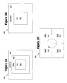
FIGS. 3A, 3B, and 3C illustrate several ways to encode a video feed using ROIs, according to an exemplary embodiment of the elastic expert system 110. Conventional methods for implementing ROIs comprise automatic and semi-automatic ROIs. Automatic methods perform the task of determination and tracking of the ROI, whereas semi-automatic methods leave the determination as a periodic task for the user to perform, and track a complex ROI contour representing the ROI boundary between these intervals. These methods are characterized by their complexity, but they lack a commensurate performance improvement. Hence, there is a motivation to perform tracking in a more simple but logical manner.
In FIG. 3A, a video image 300 is encoded by utilizing conventional ROI 305, EROI 310, and BKGRND 315. By utilizing an EROI 310, between the ROI 305 and BKGRND 315, the bit rate allocation between each region is less dramatic because the bit rate allocation is gradually stepped down in each region.
In FIG. 3B, the video image 300 is encoded using an ROI 305 and BKGRND 315 only. To aid in visual perception and reliability, this ROI 305 may be a preset size and placed in the middle of the image 300. According to an exemplary embodiment of the elastic expert system 110, additional elasticity is added to the expert system by allowing the size of the ROI to be assigned variable sizes, such as ¼, 1/9, and 1/16 of the video image size, and may be adjustable between each size. It is proposed to have simple templates for the ROI, with the size and shape of this template coming from among a small set of acceptable choices (e.g. elliptical ROI, ¼ the size of the image). The user may specify the template, and its center location. Once selected, all that changes until the user resets the ROI is the center location of the ROI template. The tracking algorithm determines the center location of the ROI template from frame to frame through a simple methodology based on color and motion information. For example, a new center location may be determined based on the estimated average horizontal and vertical displacements to the ROI template, which can be obtained using motion vectors.
FIG. 3C illustrates a method for encoding the video image 300, where the ROI 305 rotates around the video image 300 at a preset sampling frequency. This particular exemplary embodiment may be particularly applicable for the monitoring of surveillance video. In FIG. 3C, the ROI is depicted as rotating in a clockwise fashion, starting with the right hand corner at ROI 305A. At this ROI 305A, the BKGRND fills the other areas of the video image 300. At a preset frequency, the ROI 305A-D rotates around the screen in a clockwise fashion, covering BKGRND at respective portions. In this way, if the ROI 305 is rotated fast enough, each block of the screen will change from BKGRND to ROI quickly enough so that the actual region of interest in the video scene, even if not known apriori, will be captured with an adequate sampling frequency.
As discussed with reference to FIG. 2, the elastic expert system 110 encodes the video feed 105 according to four levels of quality: mathematical losslessness (ML) (i.e., there is no loss of any digital information); perceptual losslessness (PL) (i.e., there is no visual distinguish-ability with the original video); functional losslessness (FL) (i.e., there may be visually perceivable artifacts, but they do not compromise functional assessment); and best effort (BE) (i.e., where the video quality is not distracting or annoying). To quantify these levels of video quality, a functional hierarchy assessment is performed (although it is noted that ML is not required to be determined from the functional hierarchy assessment, because mathematical losslessness (ML) is a mathematically deterministic video quality level (unlike PL, FL, and BE), obtained when no quantization based compression is applied). Based on the functional hierarchy assessment (and determination of a value for ML), the application domain requirements for the elastic expert system 110 can be set.
FIG. 4 illustrates a method for implementing a functional hierarchy assessment, according to an exemplary embodiment. At step 405, subjects are identified for the functional hierarchy assessment. If the purpose of the elastic expert system 110 is to be utilized in a tele-health or tele-medicine environment, then physician experts would be identified and selected as the test subjects.
Once the subjects are identified, a video with uniform spatial quality is played for the subjects at step 410. As the video is played, the subjects are asked to give a functional assessment of the features and perceptual losslessness of the video. In an exemplary embodiment, the subjects may be asked to: (at step 415A) identify identifiable features in the video; (at step 415B) quantify the video quality based on whether a diagnostic or functional assessment could be made from the video; (at step 415C) qualify whether the video appears to be perceptually perfect; and (at step 415D) make a note of any artifacts they see in the video. Once the video has been shown at one compression bit rate, at step 420, the compression rate of the video is randomly adjusted and the functional assessment at steps 410 and 415 is repeated. This cycle continues until a significant number of compression rates have been analyzed.
Using the results from the functional assessments gathered for each bit rate shown to the subjects, the average of the results can be taken at step 425 to determine PL, FL, and BE. Specifically, If TBR_FLi represents the TBR required for FL for feature i averaged over several experts and TBR_PL and TBR_BE represents the TBR required for PL and BE, respectively, also averaged over several experts, then the corresponding bits per pixel (bpp) required for each losslessness can be expressed as:
bpp_FLi = TBR_FLi FR_RATE × FR_SIZE bpp_PL = TBR_PL FR_RATE × FR_SIZE bpp_BE = TBR_BE FR_RATE × FR_SIZE
where FR_RATE represents the frame rate (in frames per second) and FR_SIZE represents the spatial resolution of the training videos (assuming one fixed value). To obtain one value bpp_FL encompassing all features i, there are two possibilities—the mean, or the maximum value. This step achieves the quantification of video quality.
As a practical example of the above, doctors could be used as subjects for the functional hierarchy assessment. A set of training videos are played for the doctors at a variety of total bit rates (TBR) and uniform spatial quality. The doctors are then asked to identify maximum levels of compression that can be applied while retaining certain levels of quality. The compressed training videos are presented in random order to the doctors and they complete an evaluation whose format is shown in Table 1, which in this example is specific to pediatric respiratory distress.
TABLE 1
Random
Video Feature FL? PL?
Sample Sets (1-4) (Yes/No) Comments
1-n RR
OC
WB
. . .
As illustrated in the evaluate illustrated in Table 1, each doctor evaluates each of the videos according to the evaluation template shown, where the feature sets identified in this example stand for a rib retraction (RR), oral cyanosis (OC), and work of breathing (WB). Each sample number represents a video at a particular total bit rate (TBR). The physician expert lists whichever features he/she can identify in the video at that particular bit-rate. The remaining three columns represent the quantification of the video quality information. In the “FL?” column, the four options relate to the quality of the video for clinical (i.e., functional) assessment of each feature set: 1—No, 2—Maybe Not, 3—Likely, 4 —Yes. The lowest TBR at which the evaluation is 4 represents the threshold FL for the particular feature. Similarly, the lowest TBR at which “PL?” is ‘Yes’ represents the PL threshold for the particular video. In the ‘Comments’ column, the expert identifies any annoying or distracting artifacts in the video. This information can be used to obtain the threshold for BE for the particular video. It should be noted that the above table represents one video evaluated by one particular expert, whereas the complete test set consists of several videos evaluated by several physician experts.
After completing the functional hierarchy assessment, the elastic expert system 110 is made adaptive to network conditions through the notion of an encoder state. An encoder state is defined by a pair of levels, one corresponding to the ROI, and the other corresponding to the BKGRND. The notion of an encoder state also helps the encoder use the information on application domain requirements and map them to the ROI and BKGRND regions in the video. The complete state table for the encoder is shown in Table 2.
TABLE 2
BG
ROI ML PL FL BE
ML
1 2 3 4
PL n/a 5 6 7
FL n/a n/a 8 9
BE n/a n/a n/a 10
The states are numbered 1 to 10 according to decreasing priority, based on the premise that the ROI quality should be at least the same as or better than the BKGRND quality. For example, state 2 represents ML quality ROI and PL quality BKGRND, and state 8 represents FL quality ROI and FL quality BKGRND. Based on this design, at very low TBR, ROI quality will not be of a functional-lossless level, and at very high TBR, the entire frame quality can be of a mathematical-lossless level. In between these TBR, the design is expected to have high value because of elastic associations between different levels of losslessness and different regions in the scene. For example, in narrowband environments, the design can achieve FL ROI quality, whereas in broadband environments, the design can achieve ML ROI and PL BKGRND qualities.
To determine which state the elastic expert system 110 is in, a group of pictures (GOP)-level bit allocation algorithm is utilized, based on nominal bpp values for PL, FL, and BE quality levels. State determination is done at the GOP level in order to average over I, P, and B frames. For the video currently being encoded, the nominal number of bits required per GOP for DL in the ROI denoted by R_ROI_FL, for example, is:
R_ROI_FL=bpp_FL×ROI_SIZE×N_GOP
ROI_SIZE is the average size of the ROI for the current GOP, and may be a window of standard shape and size around the feature(s). N_GOP denotes the number of frames in GOP. Similar expressions hold for the nominal number of bits required for other quality levels for the ROI and BKGRND.
FIG. 5 illustrates a method for determining states in the elastic expert system 110, according to an exemplary embodiment. At the beginning of a new GOP, the encoder tries to occupy the highest priority state given the current TBR. At step 505A, the elastic expert system 110 determines if enough bits are present for it to enter state 1. Specifically, if R denotes the target number of bits in a GOP, the encoder checks if it can occupy state 1, governed by the condition: R>R_ROI_ML+R_BKGRND_ML (i.e., are the total bits available greater than those necessary to have a mathematically lossless region-of-interest and background)? If so, the elastic expert system 110 occupies state 1 at step 510A. Otherwise the system 110 checks if it can occupy state 2 at step 505B. According to the exemplary embodiment in Table 2, state 2 is governed by the condition: R>R_ROI_ML+R_BKGRND_PL (i.e., are the total bits available greater than those necessary to have a mathematically lossless region-of-interest and perceptually lossless background)? If yes, then state 2 is entered. If no, then the elastic expert system 110 continues until it occupies one of the ten possible exemplary states, as summarized in Table 2 and FIG. 5.
In each state, the BKGRND is allocated bits first, and then the remaining bits are allocated to the ROI. This is done to ensure that the ROI gets bits in excess of the nominal value. For example, in state 9, where the ROI has FL quality, and BKGRND has BE quality, the allocation is done as follows:
R_BKGRND=R_BKGRND_BE
R_ROI=R−R_BKGRND
R_ROI and R_BKGRND denote the target number of bits in a GOP for the ROI and BKGRND, respectively. If the encoder determines that state 9 is the current GOP state, the BKGRND gets assigned R_BKGRND_BE bits, and the ROI gets assigned at least R_BKGRND_FL bits. The only exception is state 10, where all the bits are allocated to the ROI.
At a given TBR, the encoder occupies a particular state, which is the highest priority under the given conditions. When the TBR changes, as in a variable bit rate (VBR) channel, the encoder will likely transition to a new state at the beginning of a new GOP. Depending on the change in TBR, the encoder may move to a higher priority state or a lower priority state. In this way, the elastic system achieves its two intended goals: (a) user-specified quality through incorporation of user inputs at the beginning of the design process itself, and (b) robustness to variability and limitations in channel TBR.
In a further exemplary embodiment, the states of the elastic expert system 110 may be periodically changed or shifted to increase the visual perception of the ROI. For example, for FL, the average bpp value over the features is chosen as the nominal value. Accordingly, the ROI may not be of FL quality even if its current state indicates that it should be so. Similarly, because PL and BE are subjective notions of quality, these functional assessments may vary from viewer to viewer. Therefore, a quality level for the ROI as indicated by a particular state might not indeed be achieved as far as the current viewer of the video is concerned. To alleviate this problem, the elastic expert system 110, according to an exemplary embodiment, allocates more bits to the ROI whenever such a condition is detected. This allocation is done by a state transition from the current state to the next lower priority state in the same row. For example, suppose the encoder transitions from state 6 to state 7:
STATE 6 : R_BKGRND = R_BKGRND _FL R_ROI = R - R_BKGRND STATE 7 : R_BKGRND = R_BKGRND _BE R_ROI = R - R_BKGRND
Clearly, at a given TBR, R_ROI is higher in state 7 than in state 6. Transitions are not allowed to states in lower rows because the ROI quality level changes across rows. Instead, in states 4, 7, and 9, where the encoder is at the far end of a row (i.e., with BE quality BKGRND), R_ROI is increased by a parameter update i.e., by simply reducing R_BKGRND to a new, lower value R_BKGRND_BE_MIN, compared to R_BKGRND_BE.
There are two ways to detect when ROI quality is insufficient. First, a manual trigger may be used to indicate that video quality within the ROI is unsatisfactory. That is, a remote viewer may send an indication through the network that the state of the elastic expert system 110 needs to be shifted. This option is straightforward, yet cumbersome. Thus, an automatic trigger is preferred.
An automatic trigger may be used to indicate that video quality within the ROI is unsatisfactory. Various quality metrics, including a PSNR-difference approach between the ROI and BKGRND, a constant ROI PSNR approach, are options to automatically trigger a state transition or parameter update.
Once bits have been allocated to each region (according to any exemplary embodiment), the bits can be related to the quantization parameter (Q) to perform encoding of the video. Accordingly, as illustrated at step 610 of FIG. 6, Lagrangian optimization leads to the following expression for the ROI Q in one exemplary embodiment:
Q l , ROI f = AK σ i , ROI f i = 1 N σ i , ROI f ω i , ROI f ( B T , ROI f - AN ROI C ) ω i , ROI f
The subscript i represents the macroblock (MB) number, the superscript f represents the frame number, BT,ROI f is the target number of bits for the ROI, σT,ROI f is the variance of the ith MB of the ROI, ωT,ROI f is the distortion weight for the ROI MB, A is the number of pixels in a MB, NROI is the number of MBs in the ROI, C is the overhead rate, and K is a constant. Bf T,ROI provides an additional degree of freedom over distortion weights to control ROI quality. Note that this is only dependent on the bits allocated to the ROI (Bf T,ROI) at step 610, and the distortion weights for the ROI. Thus similar processes are performed at steps 605 and 615 to determine the quantization parameters for the EROI and BKGRND regions of the frame.
In addition to the exemplary embodiments discussed above, which allocate bits differently between different spatial regions such as the ROI and BKGNRD, in an alternative exemplary embodiment, or in addition to the exemplary embodiment discussed above, a temporal approach may be used wherein the BKGRND is encoded less often than the ROI. For example, in a remote assessment application, the ROI may need to be transmitted at the highest frame rate e.g. 30 frames per second (fps). On the other hand, the BKGRND may not be needed that often, and hence may be transmitted at a sub-sampled rate (e.g., 5 fps). Utilizing this approach therefore offers significant savings in bits.
FIG. 7 illustrates another exemplary embodiment of the elastic expert system 110. By distributing the target bits for the frame between each region—ROI, EROI, and BKGRND, bit allocation is shifted from the frame level to individual regions. Therefore, when a frame arrives at step 705, the network resources 710 are evaluated to determine a target number of bits available for the entire frame (BT f), where the superscript f represents the frame number. Subject to the constraint that the total bit rate available is equal to the bit rate from the ROI (BT,ROI f), EROI (BT,EROI f), and BKGRND (BT,BKGRND f), expressed as,
B T,ROI f +B T,EROI f +B T,BKGRND f =B T f
selecting the parameters for the three regions is a major step towards achieving the envisioned elastic system 110. As illustrated at step 715, the elastic expert system 110 determines the regional bit allocation by incorporating size 720A and motion features 720B as follows:
B T , ROI = ( α SIZE S ROI + α MOTION M ROI ) B T f B T , EROI = ( α SIZE S EROI + α MOTION M EROI ) B T f B T , BKGRND = ( α SIZE S BKGRND + α MOTION M BKGRND ) B T f where , S ROI = N ROI N , S EROI = N EROI N , S BKGRND = N BKGRND N M ROI = ROI MV FRAME MV , M EROI = EROI MV FRAME MV , M BKGRND = BKGRND MV FRAME MV
The S parameters are the normalized region size parameters, and the M parameters are the normalized region activity descriptors—obtained from the motion vectors (MV) of each region. For example, SROI, represents the normalized size of the ROI in the video frame, and is calculated as the ratio of the number of ROI macroblocks in the video frame (NROI) to the total number of macroblocks in the video frame (N). Similarly, MROI represents the normalized motion activity in the ROI, and is calculated as the ratio of the sum of all motion vectors corresponding to ROI macroblocks to the sum of all motion vectors of all macroblocks in the video frame. The α parameters are the weights for the size and (motion parameters, with αSIZEMOTION=1. Thus, for a region, the larger its size or greater its motion, the higher the number of bits allocated.
Along with size and motion factors, perceptual features 720C may also be used. These perceptual weights are used in this exemplary embodiment to achieve bit transfer between regions as,
B T , ROI f = B T , ROI + I ROI , EROI B T , EROI + I ROI , BKGRND B T , BKGRND B T , EROI f = B T , EROI - I ROI , EROI B T , EROI + I EROI , BKGRND B T , BKGRND B T , BKGRND f = B T , BKGRND - I ROI , BKGRND B T , BKGRND - I EROI , BKGRND B T , BKGRND I x , y = i w i , x / S x j w j , y / S y · γ
where the numerator and denominator terms in the equation computing the I parameters are the normalized perceptual weights of regions x and y respectively, and γis a network-based parameter introduced to control the amount of bit transfer. Once the bits for each region have been assigned according to this embodiment, the bits can then be related to the quantization parameter (Q) to perform encoding of the video, as discussed above with reference to FIG. 6.
FIG. 8 illustrates yet another exemplary method for implementing the elastic expert system 110 (according to any exemplary embodiment). Once the bpp of the BKGRND is determined using the elastic expert system 110, video input Vin is fed to an encoder at step 805. This encoder performs uniform encoding of the entire frame at a bit rate of bppBKGRND bpp (according to the bits allocated to the BKGRND), and this results in the base bitstream (B1) at step 820. This base bitstream is then decoded to produce Vbase at step 810, which is then subtracted from Vin to result in the “error” video input, Vdiff. Vdiff is then encoded using a ROI only encoder which encodes only the ROI of the input at a bit rate of bppROI−bppBKGRND (according to the bits allocated to the ROI and BKGRND), resulting in the enhanced ROI bitstream (B2) at step 825. These two bitstreams together represent the output of the elastic expert system 110 according to this exemplary embodiment.
Although the elastic expert system 110 has been illustrated in exemplary embodiments, it is to be understood by one of ordinary skill in the art that the present disclosure has been made only by way of example, and that numerous modifications may be made without departing from the spirit and scope of the methods and systems hereinafter claimed.

Claims (20)

1. A method for allocating bits for a region-of-interest within a video feed, comprising the steps of:
determining application domain requirements for the video feed;
observing network resources available for transmitting the video feed over a network;
allocating bits for the region-of-interest within the video feed based on the application domain requirements and the network resources available; and
allocating bits for encoding a background region within the video feed based on the application domain requirements and the network resources available, where
the allocated bits are to be used to support encoding of the region-of-interest and the background region within the video feed.
2. A method for allocating bits for a region-of-interest within a video feed, comprising the steps of:
determining application domain requirements for a video feed;
observing network resources available for transmitting the video feed over a network; and
allocating bits for the region-of-interest within the video feed based on the application domain requirements and the network resources available, wherein
the allocated bits are to be used to support encoding of the region-of-interest within the video feed, and
the application domain requirements comprise values relating to one of: mathematical losslessness (ML), perceptual losslessness (PL), functional losslessness (FL), and best effort (BE).
3. The method of claim 1, further comprising the step of encoding the region-of-interest within the video feed according to the bits allocated to the region-of-interest.
4. The method of claim 1, wherein the step of allocating bits for the region-of-interest within the video feed comprises the steps of:
determining whether there are sufficient bits available on the network to occupy a state of quality according to the application domain requirements; and
if there are sufficient bits available to occupy the state of quality, allocating bits to the region-of-interest pursuant to the state of quality.
5. The method of claim 4, further comprising the steps of:
automatically identifying a new state of quality to increase visual perception in the region-of-interest; and
assigning bits to the region-of-interest based on the new state of quality.
6. The method of claim 4, further comprising the steps of:
allowing a viewer of the video feed to identify a new state of quality to increase visual perception in the region-of-interest; and
allocating bits to the region-of-interest based on the new state of quality.
7. The method of claim 4, wherein the state of quality determination is performed based on a group of pictures (GOP).
8. The method of claim 1, wherein the step of observing resources available for transmitting the video feed comprises periodically checking the network resources to observe the total bits available for transmitting the video over the network.
9. The method of claim 1, wherein the application domain requirements are static.
10. The method of claim 1, wherein the application domain requirements are dynamic.
11. The method of claim 1, wherein the region-of-interest comprises a set of pre-sized and pre-shaped templates for use within the video feed.
12. The method of claim 11, further comprising the step of enabling a viewer of the video feed to specify a size and shape of one or more of the templates and a center location for each specified template.
13. The method of claim 1, wherein the region-of-interest periodically changes locations within pre-defined areas of the video feed.
14. The method of claim 13, wherein the pre-defined areas of the video feed comprise four equally sized quadrants.
15. The method of claim 1, wherein determining the application domain requirements comprises, for each of the region of interest and the background region, determining application domain requirements for the video feed.
16. The method of claim 1, further comprising the step of encoding the background region within the video feed according to the bits allocated to the background region.
17. The method of claim 2, wherein the step of allocating bits for the region-of-interest within the video feed comprises the steps of:
determining whether there are sufficient bits available on the network to occupy a state of quality according to the application domain requirements; and
if there are sufficient bits available to occupy the state of quality, allocating bits to the region-of-interest pursuant to the state of quality.
18. The method of claim 17, further comprising the steps of:
automatically identifying a new state of quality to increase visual perception in the region-of-interest; and
assigning bits to the region-of-interest based on the new state of quality.
19. A method for allocating bits for a region-of-interest within a video feed, comprising the steps of:
determining application domain requirements for a video feed;
observing network resources available for transmitting the video feed over a network;
allocating bits for the region-of-interest within the video feed based on the application domain requirements and the network resources available; and
allocating bits for encoding an extended region-of-interest within the video feed based on the application domain requirements and the network resources available, wherein
the allocated bits are to be used to support encoding of the region-of-interest within the video feed.
20. The method of claim 19, wherein the step of allocating bits for the region-of-interest within the video feed comprises the steps of:
determining whether there are sufficient bits available on the network to occupy a state of quality according to the application domain requirements; and
if there are sufficient bits available to occupy the state of quality, allocating bits to the region-of-interest pursuant to the state of quality.
US12/226,957 2006-05-01 2007-05-01 Expert system and method for elastic encoding of video according to regions of interest Expired - Fee Related US8331436B2 (en)

Priority Applications (1)

Application Number Priority Date Filing Date Title
US12/226,957 US8331436B2 (en) 2006-05-01 2007-05-01 Expert system and method for elastic encoding of video according to regions of interest

Applications Claiming Priority (3)

Application Number Priority Date Filing Date Title
US79648006P 2006-05-01 2006-05-01
PCT/US2007/010579 WO2007130425A2 (en) 2006-05-01 2007-05-01 Expert system and method for elastic encoding of video according to regions of interest
US12/226,957 US8331436B2 (en) 2006-05-01 2007-05-01 Expert system and method for elastic encoding of video according to regions of interest

Publications (2)

Publication Number Publication Date
US20090232203A1 US20090232203A1 (en) 2009-09-17
US8331436B2 true US8331436B2 (en) 2012-12-11

Family

ID=38668264

Family Applications (1)

Application Number Title Priority Date Filing Date
US12/226,957 Expired - Fee Related US8331436B2 (en) 2006-05-01 2007-05-01 Expert system and method for elastic encoding of video according to regions of interest

Country Status (2)

Country Link
US (1) US8331436B2 (en)
WO (1) WO2007130425A2 (en)

Families Citing this family (11)

* Cited by examiner, † Cited by third party
Publication number Priority date Publication date Assignee Title
US6503231B1 (en) 1998-06-10 2003-01-07 Georgia Tech Research Corporation Microneedle device for transport of molecules across tissue
US6743211B1 (en) * 1999-11-23 2004-06-01 Georgia Tech Research Corporation Devices and methods for enhanced microneedle penetration of biological barriers
US6611707B1 (en) 1999-06-04 2003-08-26 Georgia Tech Research Corporation Microneedle drug delivery device
EP1345646A2 (en) * 2000-12-14 2003-09-24 Georgia Tech Research Corporation Microneedle devices and production thereof
WO2007014216A2 (en) 2005-07-22 2007-02-01 Cernium Corporation Directed attention digital video recordation
BRPI0906767A2 (en) * 2008-01-18 2015-07-14 Thomson Licensing Method for Perceptual Quality Assessment
US9215467B2 (en) * 2008-11-17 2015-12-15 Checkvideo Llc Analytics-modulated coding of surveillance video
US8363720B2 (en) * 2009-01-26 2013-01-29 Panasonic Corporation Moving image processing device, moving image processing method and imaging apparatus
WO2010144566A1 (en) * 2009-06-09 2010-12-16 Wayne State University Automated video surveillance systems
CN103428523B (en) * 2012-05-22 2015-07-08 华为技术有限公司 Method and device for estimating video quality
US10958955B1 (en) * 2018-09-13 2021-03-23 Amazon Technologies, Inc. System for generating modified video output

Citations (15)

* Cited by examiner, † Cited by third party
Publication number Priority date Publication date Assignee Title
US5717464A (en) * 1995-12-18 1998-02-10 Divicom, Inc. Rate control for a video encoder
US5734843A (en) * 1995-06-07 1998-03-31 Advanced Micro Devices Inc. Reverse data channel as a bandwidth modulator
US5799111A (en) 1991-06-14 1998-08-25 D.V.P. Technologies, Ltd. Apparatus and methods for smoothing images
US6178204B1 (en) 1998-03-30 2001-01-23 Intel Corporation Adaptive control of video encoder's bit allocation based on user-selected region-of-interest indication feedback from video decoder
US6195394B1 (en) 1998-11-30 2001-02-27 North Shore Laboratories, Inc. Processing apparatus for use in reducing visible artifacts in the display of statistically compressed and then decompressed digital motion pictures
US6256423B1 (en) 1998-09-18 2001-07-03 Sarnoff Corporation Intra-frame quantizer selection for video compression
US6437821B1 (en) 1999-12-22 2002-08-20 Tektronix, Inc. Harmonic measurement of blockiness in video signals
US20030051843A1 (en) 2001-09-14 2003-03-20 The Research Foundation Of State University Of New York Method and system for characterizing streak defects in web structures
US20030138163A1 (en) 2001-04-09 2003-07-24 Xiangrong Chen Image blur detection methods and arrangements
US20040013315A1 (en) 2002-07-18 2004-01-22 Bei Li Measurement of blurring in video sequences
US20040054758A1 (en) * 2002-09-16 2004-03-18 Chang David Fu-Tien Software application domain and storage domain constraining process and method
US20040156559A1 (en) 2002-11-25 2004-08-12 Sarnoff Corporation Method and apparatus for measuring quality of compressed video sequences without references
US20060072673A1 (en) 2004-10-06 2006-04-06 Microsoft Corporation Decoding variable coded resolution video with native range/resolution post-processing operation
US20060268980A1 (en) 2005-03-25 2006-11-30 Le Dinh Chon T Apparatus and method for objective assessment of DCT-coded video quality with or without an original video sequence
US20070053575A1 (en) 2005-09-02 2007-03-08 International Business Machines Corporation System and method for detecting a streak in a compressed gray scale image

Patent Citations (15)

* Cited by examiner, † Cited by third party
Publication number Priority date Publication date Assignee Title
US5799111A (en) 1991-06-14 1998-08-25 D.V.P. Technologies, Ltd. Apparatus and methods for smoothing images
US5734843A (en) * 1995-06-07 1998-03-31 Advanced Micro Devices Inc. Reverse data channel as a bandwidth modulator
US5717464A (en) * 1995-12-18 1998-02-10 Divicom, Inc. Rate control for a video encoder
US6178204B1 (en) 1998-03-30 2001-01-23 Intel Corporation Adaptive control of video encoder's bit allocation based on user-selected region-of-interest indication feedback from video decoder
US6256423B1 (en) 1998-09-18 2001-07-03 Sarnoff Corporation Intra-frame quantizer selection for video compression
US6195394B1 (en) 1998-11-30 2001-02-27 North Shore Laboratories, Inc. Processing apparatus for use in reducing visible artifacts in the display of statistically compressed and then decompressed digital motion pictures
US6437821B1 (en) 1999-12-22 2002-08-20 Tektronix, Inc. Harmonic measurement of blockiness in video signals
US20030138163A1 (en) 2001-04-09 2003-07-24 Xiangrong Chen Image blur detection methods and arrangements
US20030051843A1 (en) 2001-09-14 2003-03-20 The Research Foundation Of State University Of New York Method and system for characterizing streak defects in web structures
US20040013315A1 (en) 2002-07-18 2004-01-22 Bei Li Measurement of blurring in video sequences
US20040054758A1 (en) * 2002-09-16 2004-03-18 Chang David Fu-Tien Software application domain and storage domain constraining process and method
US20040156559A1 (en) 2002-11-25 2004-08-12 Sarnoff Corporation Method and apparatus for measuring quality of compressed video sequences without references
US20060072673A1 (en) 2004-10-06 2006-04-06 Microsoft Corporation Decoding variable coded resolution video with native range/resolution post-processing operation
US20060268980A1 (en) 2005-03-25 2006-11-30 Le Dinh Chon T Apparatus and method for objective assessment of DCT-coded video quality with or without an original video sequence
US20070053575A1 (en) 2005-09-02 2007-03-08 International Business Machines Corporation System and method for detecting a streak in a compressed gray scale image

Non-Patent Citations (1)

* Cited by examiner, † Cited by third party
Title
International Search Report, PCT/US2007/010579, Jul. 3, 2008, United States Patent and Trademark Office.

Also Published As

Publication number Publication date
US20090232203A1 (en) 2009-09-17
WO2007130425A2 (en) 2007-11-15
WO2007130425A3 (en) 2008-08-28

Similar Documents

Publication Publication Date Title
US8331436B2 (en) Expert system and method for elastic encoding of video according to regions of interest
US6826308B2 (en) Method and apparatus for image encoding and decoding using a shape and position map
JP3365730B2 (en) Apparatus and method for adjusting bit generation amount for video encoding
EP2309747A2 (en) Region-of-interest coding using RHO domain bit allocation
KR101439484B1 (en) Method and apparatus for decording video considering noise
EP1601203A2 (en) Mosquito noise detection and reduction
JPH11177983A (en) Image compression processor
KR20150054554A (en) Apparatus and method for processing image
US20150256822A1 (en) Method and Apparatus for Assessing Video Freeze Distortion Degree
Rao et al. Delivering diagnostic quality video over mobile wireless networks for telemedicine
Wang et al. Toward optimal rate control: a study of the impact of spatial resolution, frame rate, and quantization on subjective video quality and bit rate
KR20040062732A (en) Bit rate control system based on object
Razaak et al. Rate-distortion and rate-quality performance analysis of HEVC compression of medical ultrasound videos
CN108737826B (en) Video coding method and device
Dumić et al. Subjective quality assessment of H. 265 versus H. 264 video coding for high-definition video systems
US11153606B2 (en) Face region detection based light field video compression
Moretti et al. Content/context-aware multiple camera selection and video adaptation for the support of m-health services
US20070031050A1 (en) Method and apparatus for bit rate control for image encoding
Daly et al. Visual eccentricity models in face-based video compression
Stachura et al. Region of interest video compression: delivering diagnostic quality video over limited throughput mobile telemedicine networks
US20090207916A1 (en) System and method for allocating bitstream of scalable video coding
Klink et al. An Impact of the Encoding Bitrate on the Quality of Streamed Video Presented on Screens of Different Resolutions
Agrafiotis et al. A video coding system for sign language communication at low bit rates
Hewage et al. Quality evaluation of asymmetric compression for 3d surgery video
Vincent et al. Modeling of the coding gain of joint coding for multi-program video transmission

Legal Events

Date Code Title Description
AS Assignment

Owner name: OMET S.R.I., ITALY

Free format text: ASSIGNMENT OF ASSIGNORS INTEREST;ASSIGNOR:BARTESAGHI, ANGELO;REEL/FRAME:021799/0982

Effective date: 20081021

AS Assignment

Owner name: GEORGIA TECH RESEARCH CORPORATION, GEORGIA

Free format text: ASSIGNMENT OF ASSIGNORS INTEREST;ASSIGNORS:JAYANT, NUGGENHALLY SAMPATH;RAO, SIRA P.;REEL/FRAME:021798/0437;SIGNING DATES FROM 20080926 TO 20080930

Owner name: GEORGIA TECH RESEARCH CORPORATION, GEORGIA

Free format text: ASSIGNMENT OF ASSIGNORS INTEREST;ASSIGNORS:JAYANT, NUGGENHALLY SAMPATH;RAO, SIRA P.;SIGNING DATES FROM 20080926 TO 20080930;REEL/FRAME:021798/0437

REMI Maintenance fee reminder mailed
LAPS Lapse for failure to pay maintenance fees
STCH Information on status: patent discontinuation

Free format text: PATENT EXPIRED DUE TO NONPAYMENT OF MAINTENANCE FEES UNDER 37 CFR 1.362

FP Lapsed due to failure to pay maintenance fee

Effective date: 20161211