US8336546B2 - Positive airway pressure system with head control - Google Patents
Positive airway pressure system with head control Download PDFInfo
- Publication number
- US8336546B2 US8336546B2 US13/244,891 US201113244891A US8336546B2 US 8336546 B2 US8336546 B2 US 8336546B2 US 201113244891 A US201113244891 A US 201113244891A US 8336546 B2 US8336546 B2 US 8336546B2
- Authority
- US
- United States
- Prior art keywords
- pressure
- patient
- head
- housing
- supine
- Prior art date
- Legal status (The legal status is an assumption and is not a legal conclusion. Google has not performed a legal analysis and makes no representation as to the accuracy of the status listed.)
- Active
Links
Images


Classifications
-
- A—HUMAN NECESSITIES
- A61—MEDICAL OR VETERINARY SCIENCE; HYGIENE
- A61M—DEVICES FOR INTRODUCING MEDIA INTO, OR ONTO, THE BODY; DEVICES FOR TRANSDUCING BODY MEDIA OR FOR TAKING MEDIA FROM THE BODY; DEVICES FOR PRODUCING OR ENDING SLEEP OR STUPOR
- A61M16/00—Devices for influencing the respiratory system of patients by gas treatment, e.g. mouth-to-mouth respiration; Tracheal tubes
- A61M16/0003—Accessories therefor, e.g. sensors, vibrators, negative pressure
-
- A—HUMAN NECESSITIES
- A61—MEDICAL OR VETERINARY SCIENCE; HYGIENE
- A61M—DEVICES FOR INTRODUCING MEDIA INTO, OR ONTO, THE BODY; DEVICES FOR TRANSDUCING BODY MEDIA OR FOR TAKING MEDIA FROM THE BODY; DEVICES FOR PRODUCING OR ENDING SLEEP OR STUPOR
- A61M16/00—Devices for influencing the respiratory system of patients by gas treatment, e.g. mouth-to-mouth respiration; Tracheal tubes
- A61M16/0051—Devices for influencing the respiratory system of patients by gas treatment, e.g. mouth-to-mouth respiration; Tracheal tubes with alarm devices
-
- A—HUMAN NECESSITIES
- A61—MEDICAL OR VETERINARY SCIENCE; HYGIENE
- A61M—DEVICES FOR INTRODUCING MEDIA INTO, OR ONTO, THE BODY; DEVICES FOR TRANSDUCING BODY MEDIA OR FOR TAKING MEDIA FROM THE BODY; DEVICES FOR PRODUCING OR ENDING SLEEP OR STUPOR
- A61M16/00—Devices for influencing the respiratory system of patients by gas treatment, e.g. mouth-to-mouth respiration; Tracheal tubes
- A61M16/0057—Pumps therefor
- A61M16/0066—Blowers or centrifugal pumps
- A61M16/0069—Blowers or centrifugal pumps the speed thereof being controlled by respiratory parameters, e.g. by inhalation
-
- A—HUMAN NECESSITIES
- A61—MEDICAL OR VETERINARY SCIENCE; HYGIENE
- A61M—DEVICES FOR INTRODUCING MEDIA INTO, OR ONTO, THE BODY; DEVICES FOR TRANSDUCING BODY MEDIA OR FOR TAKING MEDIA FROM THE BODY; DEVICES FOR PRODUCING OR ENDING SLEEP OR STUPOR
- A61M16/00—Devices for influencing the respiratory system of patients by gas treatment, e.g. mouth-to-mouth respiration; Tracheal tubes
- A61M16/021—Devices for influencing the respiratory system of patients by gas treatment, e.g. mouth-to-mouth respiration; Tracheal tubes operated by electrical means
- A61M16/022—Control means therefor
- A61M16/024—Control means therefor including calculation means, e.g. using a processor
-
- A—HUMAN NECESSITIES
- A61—MEDICAL OR VETERINARY SCIENCE; HYGIENE
- A61M—DEVICES FOR INTRODUCING MEDIA INTO, OR ONTO, THE BODY; DEVICES FOR TRANSDUCING BODY MEDIA OR FOR TAKING MEDIA FROM THE BODY; DEVICES FOR PRODUCING OR ENDING SLEEP OR STUPOR
- A61M16/00—Devices for influencing the respiratory system of patients by gas treatment, e.g. mouth-to-mouth respiration; Tracheal tubes
- A61M16/06—Respiratory or anaesthetic masks
- A61M16/0605—Means for improving the adaptation of the mask to the patient
- A61M16/0616—Means for improving the adaptation of the mask to the patient with face sealing means comprising a flap or membrane projecting inwards, such that sealing increases with increasing inhalation gas pressure
-
- A—HUMAN NECESSITIES
- A61—MEDICAL OR VETERINARY SCIENCE; HYGIENE
- A61M—DEVICES FOR INTRODUCING MEDIA INTO, OR ONTO, THE BODY; DEVICES FOR TRANSDUCING BODY MEDIA OR FOR TAKING MEDIA FROM THE BODY; DEVICES FOR PRODUCING OR ENDING SLEEP OR STUPOR
- A61M16/00—Devices for influencing the respiratory system of patients by gas treatment, e.g. mouth-to-mouth respiration; Tracheal tubes
- A61M16/06—Respiratory or anaesthetic masks
- A61M16/0683—Holding devices therefor
-
- A—HUMAN NECESSITIES
- A61—MEDICAL OR VETERINARY SCIENCE; HYGIENE
- A61M—DEVICES FOR INTRODUCING MEDIA INTO, OR ONTO, THE BODY; DEVICES FOR TRANSDUCING BODY MEDIA OR FOR TAKING MEDIA FROM THE BODY; DEVICES FOR PRODUCING OR ENDING SLEEP OR STUPOR
- A61M16/00—Devices for influencing the respiratory system of patients by gas treatment, e.g. mouth-to-mouth respiration; Tracheal tubes
- A61M16/08—Bellows; Connecting tubes ; Water traps; Patient circuits
- A61M16/0875—Connecting tubes
-
- A—HUMAN NECESSITIES
- A61—MEDICAL OR VETERINARY SCIENCE; HYGIENE
- A61M—DEVICES FOR INTRODUCING MEDIA INTO, OR ONTO, THE BODY; DEVICES FOR TRANSDUCING BODY MEDIA OR FOR TAKING MEDIA FROM THE BODY; DEVICES FOR PRODUCING OR ENDING SLEEP OR STUPOR
- A61M16/00—Devices for influencing the respiratory system of patients by gas treatment, e.g. mouth-to-mouth respiration; Tracheal tubes
- A61M16/20—Valves specially adapted to medical respiratory devices
- A61M16/201—Controlled valves
- A61M16/202—Controlled valves electrically actuated
- A61M16/203—Proportional
- A61M16/204—Proportional used for inhalation control
-
- A—HUMAN NECESSITIES
- A61—MEDICAL OR VETERINARY SCIENCE; HYGIENE
- A61M—DEVICES FOR INTRODUCING MEDIA INTO, OR ONTO, THE BODY; DEVICES FOR TRANSDUCING BODY MEDIA OR FOR TAKING MEDIA FROM THE BODY; DEVICES FOR PRODUCING OR ENDING SLEEP OR STUPOR
- A61M16/00—Devices for influencing the respiratory system of patients by gas treatment, e.g. mouth-to-mouth respiration; Tracheal tubes
- A61M16/0003—Accessories therefor, e.g. sensors, vibrators, negative pressure
- A61M2016/0027—Accessories therefor, e.g. sensors, vibrators, negative pressure pressure meter
-
- A—HUMAN NECESSITIES
- A61—MEDICAL OR VETERINARY SCIENCE; HYGIENE
- A61M—DEVICES FOR INTRODUCING MEDIA INTO, OR ONTO, THE BODY; DEVICES FOR TRANSDUCING BODY MEDIA OR FOR TAKING MEDIA FROM THE BODY; DEVICES FOR PRODUCING OR ENDING SLEEP OR STUPOR
- A61M2205/00—General characteristics of the apparatus
- A61M2205/33—Controlling, regulating or measuring
- A61M2205/3303—Using a biosensor
-
- A—HUMAN NECESSITIES
- A61—MEDICAL OR VETERINARY SCIENCE; HYGIENE
- A61M—DEVICES FOR INTRODUCING MEDIA INTO, OR ONTO, THE BODY; DEVICES FOR TRANSDUCING BODY MEDIA OR FOR TAKING MEDIA FROM THE BODY; DEVICES FOR PRODUCING OR ENDING SLEEP OR STUPOR
- A61M2205/00—General characteristics of the apparatus
- A61M2205/33—Controlling, regulating or measuring
- A61M2205/332—Force measuring means
-
- A—HUMAN NECESSITIES
- A61—MEDICAL OR VETERINARY SCIENCE; HYGIENE
- A61M—DEVICES FOR INTRODUCING MEDIA INTO, OR ONTO, THE BODY; DEVICES FOR TRANSDUCING BODY MEDIA OR FOR TAKING MEDIA FROM THE BODY; DEVICES FOR PRODUCING OR ENDING SLEEP OR STUPOR
- A61M2205/00—General characteristics of the apparatus
- A61M2205/33—Controlling, regulating or measuring
- A61M2205/3331—Pressure; Flow
- A61M2205/3355—Controlling downstream pump pressure
-
- A—HUMAN NECESSITIES
- A61—MEDICAL OR VETERINARY SCIENCE; HYGIENE
- A61M—DEVICES FOR INTRODUCING MEDIA INTO, OR ONTO, THE BODY; DEVICES FOR TRANSDUCING BODY MEDIA OR FOR TAKING MEDIA FROM THE BODY; DEVICES FOR PRODUCING OR ENDING SLEEP OR STUPOR
- A61M2205/00—General characteristics of the apparatus
- A61M2205/42—Reducing noise
-
- A—HUMAN NECESSITIES
- A61—MEDICAL OR VETERINARY SCIENCE; HYGIENE
- A61M—DEVICES FOR INTRODUCING MEDIA INTO, OR ONTO, THE BODY; DEVICES FOR TRANSDUCING BODY MEDIA OR FOR TAKING MEDIA FROM THE BODY; DEVICES FOR PRODUCING OR ENDING SLEEP OR STUPOR
- A61M2205/00—General characteristics of the apparatus
- A61M2205/50—General characteristics of the apparatus with microprocessors or computers
- A61M2205/52—General characteristics of the apparatus with microprocessors or computers with memories providing a history of measured variating parameters of apparatus or patient
-
- A—HUMAN NECESSITIES
- A61—MEDICAL OR VETERINARY SCIENCE; HYGIENE
- A61M—DEVICES FOR INTRODUCING MEDIA INTO, OR ONTO, THE BODY; DEVICES FOR TRANSDUCING BODY MEDIA OR FOR TAKING MEDIA FROM THE BODY; DEVICES FOR PRODUCING OR ENDING SLEEP OR STUPOR
- A61M2205/00—General characteristics of the apparatus
- A61M2205/70—General characteristics of the apparatus with testing or calibration facilities
-
- A—HUMAN NECESSITIES
- A61—MEDICAL OR VETERINARY SCIENCE; HYGIENE
- A61M—DEVICES FOR INTRODUCING MEDIA INTO, OR ONTO, THE BODY; DEVICES FOR TRANSDUCING BODY MEDIA OR FOR TAKING MEDIA FROM THE BODY; DEVICES FOR PRODUCING OR ENDING SLEEP OR STUPOR
- A61M2205/00—General characteristics of the apparatus
- A61M2205/82—Internal energy supply devices
- A61M2205/8206—Internal energy supply devices battery-operated
-
- A—HUMAN NECESSITIES
- A61—MEDICAL OR VETERINARY SCIENCE; HYGIENE
- A61M—DEVICES FOR INTRODUCING MEDIA INTO, OR ONTO, THE BODY; DEVICES FOR TRANSDUCING BODY MEDIA OR FOR TAKING MEDIA FROM THE BODY; DEVICES FOR PRODUCING OR ENDING SLEEP OR STUPOR
- A61M2205/00—General characteristics of the apparatus
- A61M2205/82—Internal energy supply devices
- A61M2205/8218—Gas operated
-
- A—HUMAN NECESSITIES
- A61—MEDICAL OR VETERINARY SCIENCE; HYGIENE
- A61M—DEVICES FOR INTRODUCING MEDIA INTO, OR ONTO, THE BODY; DEVICES FOR TRANSDUCING BODY MEDIA OR FOR TAKING MEDIA FROM THE BODY; DEVICES FOR PRODUCING OR ENDING SLEEP OR STUPOR
- A61M2205/00—General characteristics of the apparatus
- A61M2205/82—Internal energy supply devices
- A61M2205/8262—Internal energy supply devices connectable to external power source, e.g. connecting to automobile battery through the cigarette lighter
-
- A—HUMAN NECESSITIES
- A61—MEDICAL OR VETERINARY SCIENCE; HYGIENE
- A61M—DEVICES FOR INTRODUCING MEDIA INTO, OR ONTO, THE BODY; DEVICES FOR TRANSDUCING BODY MEDIA OR FOR TAKING MEDIA FROM THE BODY; DEVICES FOR PRODUCING OR ENDING SLEEP OR STUPOR
- A61M2209/00—Ancillary equipment
- A61M2209/08—Supports for equipment
- A61M2209/088—Supports for equipment on the body
-
- A—HUMAN NECESSITIES
- A61—MEDICAL OR VETERINARY SCIENCE; HYGIENE
- A61M—DEVICES FOR INTRODUCING MEDIA INTO, OR ONTO, THE BODY; DEVICES FOR TRANSDUCING BODY MEDIA OR FOR TAKING MEDIA FROM THE BODY; DEVICES FOR PRODUCING OR ENDING SLEEP OR STUPOR
- A61M2210/00—Anatomical parts of the body
- A61M2210/06—Head
-
- A—HUMAN NECESSITIES
- A61—MEDICAL OR VETERINARY SCIENCE; HYGIENE
- A61M—DEVICES FOR INTRODUCING MEDIA INTO, OR ONTO, THE BODY; DEVICES FOR TRANSDUCING BODY MEDIA OR FOR TAKING MEDIA FROM THE BODY; DEVICES FOR PRODUCING OR ENDING SLEEP OR STUPOR
- A61M2230/00—Measuring parameters of the user
- A61M2230/005—Parameter used as control input for the apparatus
-
- A—HUMAN NECESSITIES
- A61—MEDICAL OR VETERINARY SCIENCE; HYGIENE
- A61M—DEVICES FOR INTRODUCING MEDIA INTO, OR ONTO, THE BODY; DEVICES FOR TRANSDUCING BODY MEDIA OR FOR TAKING MEDIA FROM THE BODY; DEVICES FOR PRODUCING OR ENDING SLEEP OR STUPOR
- A61M2230/00—Measuring parameters of the user
- A61M2230/62—Posture
-
- A—HUMAN NECESSITIES
- A61—MEDICAL OR VETERINARY SCIENCE; HYGIENE
- A61M—DEVICES FOR INTRODUCING MEDIA INTO, OR ONTO, THE BODY; DEVICES FOR TRANSDUCING BODY MEDIA OR FOR TAKING MEDIA FROM THE BODY; DEVICES FOR PRODUCING OR ENDING SLEEP OR STUPOR
- A61M2230/00—Measuring parameters of the user
- A61M2230/63—Motion, e.g. physical activity
Definitions
- the invention is generally directed to a system and method for controlling the treatment a patient receives and particularly to controlling a Positive Airway Pressure (PAP) device.
- PAP Positive Airway Pressure
- Obstructive Sleep Apnea occurs when tissue blocks the upper airway during sleep. This will cause a drop in blood oxygen and a rise in blood carbon dioxide. The brain will sense these changes, and awaken the person enough to restore muscle tone to the structures of the upper airway, and the airway will reopen.
- the severity of OSA is determined by the number of blockages per hour of sleep, also called the apnea-hypopnea index (AHI). These include complete blockages (apneas) and partial blockages (hypopneas).
- AHI apnea-hypopnea index
- the severity of OSA, as determined by a sleep study, is classified as follows:
- OSA disrupts restorative sleep. Chronic fatigue has long been recognized as the hallmark of OSA. But more recently, large clinical studies have shown a strong link between OSA and stroke and death. This link is independent of other risk factors for cardiovascular disease such as hypertension, obesity, high cholesterol, smoking and diabetes.
- the blockage is caused by a combination of these anatomical structures.
- UPPP uvulopalatopharygoplasty
- a Repose stitch is used to tie the tongue to the mandible to prevent its posterior movement.
- Oral appliances move the mandible forward (very slightly) to create more space in the airway.
- a CPAP system such as a continuous positive airway pressure (CPAP) system.
- a CPAP system usually consists of three parts: a mask forming a largely airtight seal over the nose or nose and mouth, an air pressurizing housing or console and an elongated tube connecting the two.
- the mask contains one or more holes, usually at the junction with the tube.
- a CPAP system works by pressurizing the upper airway throughout the breathing cycle, essentially inflating the airway to keep it open.
- a CPAP system thus maintains a pneumatic splint throughout the respiratory cycle.
- a CPAP system addresses all potential blockage sites.
- the success rate in patients exceeds 80%, and its cure rate (decreasing AHI below 5) is close to 50%.
- the drawback to a CPAP system is poor patient compliance, i.e. continuous use by the patient. In one large study, only 46% of patients were compliant with a CPAP system, even though compliance was defined as using the CPAP system at least 4 hours per night at least 5 nights per week.
- Critical pressure is the airway pressure a given patient requires to maintain an open airway during sleep.
- Critical pressure is measured in cm of water, and will typically be between 6 and 14 cm of water for a patient requiring CPAP.
- the efficacy of a CPAP system goes up as pressure is increased. But, as higher pressure makes the CPAP system more uncomfortable to the patient, patient compliance drops.
- the goal of the healthcare professional in setting up a CPAP system for a patient is to achieve critical pressure without exceeding it. This will make the CPAP system both effective and tolerable.
- the pressure supplied by the CPAP system necessary to achieve critical pressure varies through the breathing cycle.
- the patient When a patient is exhaling, the patient is supplying some air pressure to the airway, and thus requires limited pressure from the CPAP system to maintain critical pressure. But when the patient is inhaling, he is decreasing pressure in the airway. During inhalation, more pressure is required by the CPAP system to maintain critical pressure in the airway.
- CPAP systems that monitor the respiratory cycle, and provide less pressure during the portions of the respiratory cycle when less external pressure is required to maintain critical pressure in the airway.
- Such adaptive systems which include systems commercially known as BiPAP and C-Flex, make CPAP systems more comfortable, improving the compliance of many patients. So, during the respiratory cycle, critical pressure does not change. But the pressure contributed by the CPAP system to maintain critical pressure changes during the respiratory cycle.
- Critical pressure can change based on sleeping position in many patients.
- Critical pressure will usually be higher when a patient is in a supine position (i.e. on his back) than when a patient is in a lateral position (on his side). This is because many of the structures that can block the airway, such as the tongue and uvula, are anterior to the airway.
- gravity pulls these structures toward the airway, and a greater pressure (critical pressure) is required to keep the airway open.
- critical pressure critical pressure
- gravity is not pulling these structures directly into the airway, and thus less pressure is required to maintain an open airway. This was demonstrated in a study published in 2001 (Penzel T. et al. 2001.
- This invention is directed to a positive airway pressure (PAP) system and method for treating of a patient with OSA or other breathing problems wherein the system has a head position sensor that is mounted onto the top of the patient's head and a pressure source that has an output pressure controlled by a head position signal from the head position sensor.
- the PAP system includes at least one housing having an interior configured to receive a system component and being configured to be secured to the top of the patient's head, preferably in a median position.
- One system component is a gas pressure source, such as a compressor, with a controllable output pressure which is disposed within the interior of the housing and preferably has a controllable motor drive.
- the gas pressure source has an outlet opening which is configured to be connected to a tubular member that preferably leads to a mask which is configured to sealingly fit over the patient's nose and/or mouth.
- the PAP system has a harness assembly which is configured to secure at least part of the system to the top a the patient's head.
- a PAP system embodying features of the invention has a head position sensor, such as an accelerometer, that is secured within or to a system housing or on or to the harness assembly that is configured to secure at least part of the PAP system to the user's head.
- the head position sensor is configured to sense the position of the patient's head with respect to a reference plane (e.g. a horizontal plane) and to generate a signal representing the sensed position of the patient's head.
- a suitable accelerometer is a Freescale 3-Axis MEMS Accelerometer (MMA845XQ), particularly the MMA8453Q model, which generates a signal series representing a three axis orientation with respect to gravity.
- controller preferably a microprocessor such as Atmel AVR Model # ATMMega328, that is provided to control the PAP system so as to adjust the output of the gas pressure source according to the sensed position of the patient's head to provide a critical pressure to the patient's airway passage to maintain patency.
- the controller is preferably secured within the system's housing and is configured to receive the head position signals transmitted from the head position sensor.
- the controller is configured to receive the head position signals and to determine a suitable pressure source output pressure for the particular sensed head position from the received head position signal.
- the controller preferably has a stored relationship between sensed head position and suitable pressure source output pressure and is configured to generate a control signal for the pressure source representing the determined suitable gas pressure.
- the control signal generated by the controller is transmitted to the pressure source, e.g. the driving motor of a compressor, to control the output of the pressure source so as to provide the determined suitable gas pressure for the sensed position of the patient's head.
- a pressure sensor senses the actual gas pressure directed to or received by the user and the controller compares the directed or received sensed pressure with the desired or determined suitable pressure and adjusts the control signal to the pressure source so as to provide the pressure source output that provides the critical pressure that maintains patency in the patient's airway passage.
- the pressure source may be operated at a constant pressure level and a control valve disposed between the pressure source and the patient's mask receives the control signal to control the output pressure.
- the control valve may be provided in the compressor outlet, in a gas flow line to the patient's mask or in the patient's mask, to provide the determined suitable gas pressure to the patient that maintains patency in the patient's airway passage.
- the accelerometer and the controller are described herein as two separate devices, they may be combined into a single device.
- the controller is configured to determine suitable compressor output pressures from the head position signal-pressure source output pressure relationship for at least two patient head positions, one head position may be a supine position and another second patient position might be a lateral position, preferably at least 20° from the supine position.
- the controller may be provided with a readable library listing a plurality of head position signals with corresponding suitable pressure source output pressures.
- the controller has a preprogrammed algorithm representing a relationship between head position signal and corresponding suitable pressure source output pressure.
- the microprocessor is configured to use the received head position signals to calculate from the algorithm suitable pressure source output pressures and generate suitable control signals for the pressure source.
- the relationship between the head position signal and suitable pressure source output pressure may be a stepped function, e.g. two or more positions with suitable pressure source output pressure or a continuous function. There may be a gradual change in pressure between stepped functions.
- the continuous function preferably has a greater rate of change in the pressure source output pressure with respect to head position with head positions between about 30° and 60° from the supine position (0°).
- the set point for a suitable pressure source output pressure for one of the head positions may be set by a health professional based upon the patient's sleep study.
- the set point for other position may also be set by the health professional.
- the supine position may be defined as within 30° of vertical, with vertical being the sleeping position where the nose is pointed directly upward, orthogonal to the sleeping plane which is horizontal.
- the pressure source is preferably a rotary blower such as the Nidec Copal TF037C, which has a turbine and a controllable drive motor.
- An alternative pressure source may be a bellows system which maintains a pressurized storage tank that provides pressurized breathing gas to the patient's mask. Other gas pressure sources may be utilized.
- the electrical power source for the pressure source drive motor is preferably a portable power source component such as one or more batteries which may be provided within the system housing.
- the electrical power source may be an electrical power cord for connection to an electrical source (e.g. a wall outlet or a separate battery pack) and may be provided to directly supply electrical power to the pressure source and/or to recharge one or more batteries.
- the electrical power source is connected to and powers the drive motor that controls the output pressure of the pressure source such as a rotary compressor.
- the system housing may be one or more separate housings, and is mounted on top of a patient's head, preferably in a medial position, by a one or more straps of the harness assembly that are secured to the housing. Other means to secure the system housing to the patient's head may be used.
- a health professional may set the output pressure of the compressor for one or more of the patient's head positions that have been based upon a sleep study performed on the patient.
- the second head position should be at least 20° away from the first head position.
- the health professional may also set the set point for the output pressure of the system when the patient's head is at other positions.
- the controller is programmed to select a suitable compressor output pressure from a preset table or library for at least one head position or determine a suitable pressure from a preprogrammed algorithm that is based upon the sensed position of the patient's head.
- the algorithm defines the relationship between the head position signal and the suitable compressor output pressure.
- the head position sensor is first calibrated, preferably when the patient's head is in a supine position.
- the calibrated head position sensor senses the patient's head position and generates a sensed head position signal which is transmitted to the controller.
- the controller determines a suitable pressure source output pressure for the sensed head position signal and generates a control signal for the pressure source to provide the suitable pressure output pressure.
- the controller compares the determined suitable pressure source output pressure with the current pressure output of the pressure source and if they differ by a specified amount, the controller generates a new control signal for the pressure source. If they do not differ by the specified amount the system loops back and continues to monitor the patient's head position.
- the pressure source output pressure requirements can vary between a low point at exhalation to a high point at inhalation for each position of the patient's head which forms an output pressure envelope for the patient.
- the position of the patient's head can be the most important determinant of critical pressure for the patient since the anatomical structures that might block the airway (such as the tongue, the soft palate, the uvula and the tonsils) are in the head.
- the position sensor that determines the position of the head can be valuable in effectively controlling the pressure output of a PAP system.
- the PAP system provides a first (higher) gas pressure from the compressor when the patient's head is in a supine position and a second (lower) pressure when the patient's head is in a lateral position.
- the gas pressure supplied to the patient when the patient's head is in a lateral position would likely be 1-8 cm of water less than the pressure supplied when the patient's head is in the supine position.
- the PAP system can vary pressure more continuously based on several patient sleeping positions. With such a system, higher pressure would be supplied to the patient by the pressure source the closer a person's head is to a completely supine position with the patient's nose lying in a vertical plane.
- Slightly lower pressure could be supplied, for example, if a person's head was 20° off from the supine position and other positions further away from the supine position.
- the lowest gas pressure would usually be when the patient's head is in a lateral position 90° or more from the supine position.
- the patient's head positions are described herein primarily in terms of the supine position, a lateral position and positions between these two positions about a longitudinal axis passing through the patient's head.
- the head position sensor may also sense when the patient's head is tilted toward or away from the patient's chest, or rotated further than a lateral position 90° away from the supine position.
- a patient whose head is tilted far forward during sleep i.e. the chin is close to the chest
- the PAP system which modulates its output pressure based on a patient's head position while sleeping could also be used to determine whether a given patient's sleep apnea event frequency and severity are affected by sleeping position, and PAP system output could be modulated accordingly.
- the PAP system pressure may be lowered from about 11 cm (of water) to about 9 cm as the patient moved from a supine to a lateral sleeping position.
- the system could also further modulate pressure output based upon whether the number of airway blockages increased or decreased (e.g. as measured by pressure sensors in the PAP mask or within the gaseous flow from the compressor to the PAP mask) and the corresponding patient position.
- the controller of the PAP system may be used to provide different pressure source output pressures within the pressure envelope at different points in the respiratory cycle at any given patient head positions. For example, higher pressure source output pressures may be provided during inhalation and lower pressure source output pressures during exhalation to maintain the critical pressure within the patient's airway passage.
- the features of this invention would allow a PAP system to provide different suitable gas pressures depending on the head position of the patient. This would improve patient comfort while providing the critical pressure at different positions to maintain an open airway. Additionally, since patients prefer lower PAP pressures, such a system might also cause patients to prefer to sleep in positions (such as a lateral position) that cause the system to provide a lower gas pressure to the patient. The lower output pressure would also spur the patient to sleep in a position that leads to fewer airway blockages. The lower output pressure would tend to disturb a person's sleep much less because of comfort of lower pressure and less noise due to the slower operation of the compressor drive motor.
- a wearable PAP system embodying features of the invention preferably has one or more housings which insulate the patient's head from heat, sound and vibration from the from the PAP system.
- a pad may be positioned at the bottom of the housing(s) or the bottom of the housing may be spaced from the patient's head to minimize such heat, noise and vibrations.
- the drive motor for the compressor may have additional vibration and noise dampers to produce a less disturbing operation. Materials such as foams, gels, plastic members, rubber-like members or contained fluids may be used to isolate and/or reduce the noise and vibrations which emanate from the pressure source.
- a PAP system embodying features of the invention may be spaced from the top of the patient head and be supported by pod extensions or feet which are secured to the harness assembly.
- the bottoms of the pod extensions or feet are preferably padded to minimize patient discomfort. Because a substantial portion of the bottom surface of the housing is spaced away from the patient's head, trapped heat underneath the bottom of the housing is minimized.
- the open space between the patient's head and the bottom of the housing(s), in addition to providing ventilation also reduces noise and vibration from the system housing to the patient.
- a self-contained PAP system embodying features of the present invention does not have a gas delivery tube connecting the patient's face mask to a remote pressure generating unit, there are fewer restrictions on a patient's movement during sleep. There is little or no likelihood of pulling the mask away from its operative position on the patient's face, and there is no remote pressure generating unit which might be pulled off an adjacent night stand.
- FIG. 1 shows a perspective view of a PAP system embodying features of the invention.
- FIG. 2 is a perspective view of a PAP system shown in FIG. 1 with a mask mounted over the patient's nose and the housing mounted on the patient's head.
- FIG. 3 is a rear view of the PAP system shown in FIG. 2 .
- FIG. 4 is a side elevational view of the system shown in FIG. 1 with portions of the system housing removed to illustrate the various components within the system housing.
- FIG. 5 is a top view of the system with portions of the system housing removed to illustrate the various components within the system housing.
- FIG. 6 is a block diagram illustrating the system shown in FIG. 1 .
- FIG. 7 is a flow diagram illustrating position calibration of the system processing.
- FIG. 8 is a flow diagram illustrating processing for a PAP system embodying features of the invention.
- FIG. 9 is a flow diagram illustrating system processing using scalar measurement.
- FIG. 10 is a top view of the PAP system shown in FIG. 2 with the patient's head in the supine position and the patient's nose pointed directly up, orthogonal to the sleeping plane.
- FIG. 11 is a top view of the PAP system with the patient's head less than 20° from the supine position.
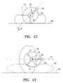
- FIG. 12 is a top view of the PAP system with the patient's head about 30°-60° from the supine position.
- FIG. 13 is a top view of the PAP system with the patient's head in the lateral position 90° from the supine position.
- FIG. 14 is a top view of the PAP system with the patient's torso in a lateral position and the patient's head in a position position greater than 60° and less than 90° from the supine position.
- FIG. 15 is a top view of the PAP system with the patient's torso in a lateral position and the patient's head in a position greater than 90° from the supine position.
- FIG. 16 shows a side view of a user with the head tilted down, bringing the chin closer to the user's chest.
- FIG. 17 shows a side view of a user with the head tilted up, moving the chin further away from the user's chest.
- FIG. 18 illustrates how different algorithms can relate head position input signals (i.e. representing degrees from a supine position) and suitable pressure source output pressures.
- FIG. 19 is a graph schematically illustrating output pressure variations within a pressure envelope for a supine and a lateral head positions.
- FIG. 20 is an exploded perspective view of a housing for a PAP system showing how the components are fit into the interior of the housing.
- FIG. 21 illustrates how the housing shown in FIG. 19 interfaces with a replaceable strap structure or harness assembly for securing the PAP system to the head of a patient or user.
- the shaded contact interface securely attaches the PAP system to the strap structure.
- FIG. 22 is a perspective view which depicts a PAP system which has multiple housings to contain the various components of the system.
- FIG. 23 is a perspective view showing a PAP system with multiple housings that are interconnected by a fabric or mesh that is integral with the harness assembly.
- FIG. 24 is a perspective view that illustrates a PAP system having multiple housings interconnected by hinged, semi-rigid elements.
- FIGS. 1-3 are perspective views of a PAP system 10 embodying features of the invention.
- the system 10 basically includes a system housing 11 and a harness assembly 12 secured to the bottom of the housing.
- the harness assembly 12 has a plurality of straps 13 and 14 and cross strap 15 to secure the housing 11 to a patient's head 16 as shown in FIG. 2 .
- the free ends of straps 13 and 14 have push in type connectors 17 and 18 , as shown in FIG. 1 , for securing the free ends to mask 20 as shown in FIG. 2 .
- the straps 13 - 15 hold the mask 20 , as shown in FIG. 2 , in a sealed engagement with the patient's nose 21 .
- the interior 22 of system housing 11 contains a compressor 23 , a controller 24 , a position sensor 25 and batteries 26 and 27 to supply electrical power to the compressor 23 .
- a gas delivery tube 28 is secured to the discharge 29 of the compressor 23 and extends to the mask 20 for the delivery of a breathable gas to the patient's nose 21 as shown in FIG. 2 .
- a system activation/calibration button 30 may be provided on the front of the housing 11 .
- An electrical power chord 31 (shown in phantom) may be provided for powering the compressor 23 directly from a separate electrical source such as an electrical outlet or battery pack (not shown) or for recharging one or more of batteries 26 and 27 .
- a vibration and sound deadening layer 32 may be provided on the bottom 33 of the system housing 11 and between the compressor 23 and supporting structure (not shown) therefore.
- FIG. 6 is a block diagram of the system 10 illustrating the interconnection of the various components of the system.
- a position signal 34 from the head position sensor 25 is transmitted to the controller 24 which in turn generates a control signal 35 for the compressor 23 based upon the received head position signal 34 .
- the controller 24 may have an input module 36 that allows for the manual input of compressor output pressure set point(s) that provides one or more suitable compressor output pressures for the compressor for one or more received head position signals 34 .
- the gas delivery tube 28 which delivers pressurized gas from the compressor 23 to the mask 20 may have a pressure sensor 37 which generates a pressure signal 38 that is fed back to the controller 24 to ensure that the desired gas pressure for the sensed patient position is delivered to the patient.
- the pressure sensor 37 may be alternatively located in the patient's mask 20 or the compressor discharge 29 .
- FIG. 7 is a flow diagram illustrating the calibration of the head position sensor 25 .
- the patient reclines into a calibration position, such as the supine position, and pushes the activation button 30 on the front of the housing 11 .
- the preferred head position for calibrating the sensor 25 is the supine position with the patient's nose is orthogonal to the sleeping plane 40 .
- the system takes a measurement from the head position sensor 25 , an accelerometer, and compares this measurement to the Gravitational constant (G). Once the measurement is within 10% of G, the value is recorded to a nonvolatile memory in the controller 24 .
- the system 10 may be calibrated by the patient or by a health professional.
- FIG. 8 is a flow diagram illustrating an operation of the calibrated PAP system 10 embodying features of the invention.
- the calibrated head position sensor 25 senses the patient's head position and generates a head position signal 34 representing then sensed head position.
- This signal 34 is transmitted (by a wire or wirelessly) to controller 24 , compares the received head position signal 34 with a stored relationship between head position signal and compressor output pressure and determines a suitable compressor output pressure for the sensed head position.
- the controller 24 compares this determined pressure output to the current pressure source output pressure, and, if the determined pressure output differs from the current pressure output by more than a specified amount, then the controller will generate a new control signal for the pressure source or compressor.
- This new control signal will control the pressure source to deliver a suitable output pressure that is delivered to the patient or user through a mask 20 so as to maintain a critical pressure within the patient's airway passage. If the determined pressure output does not differ from the current pressure output of the pressure source by more than a specified amount, the control signal will not be changed. The system 10 will continue to sense the head position of the patient and restart the loop.
- the input module 36 may be used by a health professional to input a set-point for a suitable compressor output pressure for the calibrated sensor head position that has been determined by the patient's sleep test.
- the controller 24 may continuously or periodically compare the sensed head position signal 34 from the position sensor 25 with the calibrated head position signal. If the comparison indicates that the patient's sensed head position deviates from the calibrated head position less than a certain amount, e.g. 20°, then the system will loop (providing the same control signal 34 to the compressor to provide a suitable compressor output pressure) until the controller detects a head position signal which represents a sensed head position that deviates more than the certain amount.
- a certain amount e.g. 20°
- the controller 24 determines that the sensed head position deviates more that the certain amount, such as the lateral position, the controller compares the head position signal 34 with a stored relationship between head position signal and suitable compressor output pressure to determine the suitable compressor output pressure for the new sensed head position such as the lateral head position where the patient's nose lies in a plane 41 parallel to the sleeping plane 40 when the patient's head 16 is resting on pillow 42 .
- the controller 24 then generates a new control signal 35 for the compressor to enable the compressor to provide the suitable output pressure for the sensed new lateral head position.
- the system 10 will loop providing the same output pressure until a new head position signal 34 indicates that the patient's head is in a new position which is more than 20° away from the lateral position.
- FIG. 9 A flow chart is shown in FIG. 9 illustrating a way to scale the pressure calculation as the head is moved from the calibrated position.
- the position sensor 25 an accelerometer, takes a measurement which is compared with gravity to determine if the accelerometer is stabilized. If the measurement is within 10% of G, the vector measurement of the accelerometer is converted to a scalar measurement by performing a Dot product, using the vector in the direction of the calibration position gravity. Next, a minimum pressure is added to the scalar reading and then a pressure envelop is created to control the output pressure of the pressure source.
- FIG. 10 shows the top view of a patient wearing a PAP system 10 embodying features of the invention while lying in the supine position with the head 16 and nose pointed directly up, orthogonal to the sleeping plane 40 . This is the preferred calibration position.
- a patient sleeping in the supine position will generally require a pressure that is higher than what is required in more lateral sleeping positions.
- FIG. 11 shows a top view of a patient wearing a PAP system 10 embodying features of the invention while lying with his or her torso in the supine position and the head 16 rotated slightly laterally,
- angle theta represents the deviation of the head from a true supine position, here shown to be less than 20°.
- FIG. 12 shows the top view of a patient wearing a PAP system 10 embodying features of the invention while lying with the patient's torso in the supine position and the patient's head 16 rotated more laterally.
- angle theta represents the deviation of the head from a true supine position, here shown to be between 30° and 60°.
- FIG. 13 shows a top view of a patient wearing a PAP system 10 embodying features of the invention while lying with the patient's torso in the lateral position and the head 16 of the patient in a neutral lateral position on pillow 42 with the nose pointed in a plane 41 parallel to the sleeping plane 40 .
- FIG. 14 shows a top view of a patient wearing a PAP system 10 embodying features of the invention while lying with the torso in the lateral position and the head 16 rotated toward the supine direction relative to the lateral sleeping position which is parallel to the sleeping plane 40 .
- Angle alpha represents the rotation of the patient's head from true supine position, here shown to be less than 90°.
- FIG. 15 shows the top view of a patient wearing a PAP system 10 embodying features of the invention while lying with the patient's torso in a lateral position and the patient's head 16 rotated beyond 90° from the supine position
- FIG. 16 shows a side view of a patient wearing a PAP system 10 embodying features of the invention while lying with the patient's torso and head 16 in the supine position with the head tilted forward such that the patient's chin is closer to the patient's chest.
- FIG. 17 shows a side view of a patient wearing a PAP system 10 embodying features of the invention while lying with the patient's torso and head 16 in the supine position with the head tilted backward such that the patient's chin is further from the patient's chest.
- the controller may be programmed to provide a suitable compressor output pressure for positions such as when the patient's head is rotated more than 90° from the supine position as shown in FIG. 15 and for position such as when the patient's head is tilted forward or backward as shown in FIGS. 16 and 17 .
- the stored relationship between the sensed head position signal 34 and suitable compressor output pressure may be a list of sensed head position signals with corresponding suitable compressor output pressures in a readable library in the controller 24 .
- the stored relationship may be an algorithm which defines a curve of head position verses compressor output pressure.
- Line A depicts a step function in which, at some point between supine position and a position 90° from the supine position, the pressure output drops.
- Such a step function could also have multiple steps between the supine position and 90° from the supine position, as depicted in line B.
- head position and output pressure may follow an inclined straight line, as depicted by line C.
- line C Another possibility is shown in line D which depicts a relationship in which there is a continuous pressure drop moving from a supine position to 90° from supine, but the rate of pressure drop is greatest between 30° and 60° from the supine position.
- line E Yet another relationship is shown in line E wherein there is an inclined linear portion between the supine pressure and lateral pressure between 30° and 60°.
- the pressure could continue to drop at positions greater than 90° from the supine position. Additionally, the relationship between pressure and sensed head position may have a more elaborate, advanced curve shape to provide more appropriate pressures at each position. Other relationships may be employed.
- FIG. 19 graphically illustrates a respiratory cycle through two different head positions, supine and lateral.
- the delivered pressure is higher and the respiratory cycle causes the pressure to fluctuate within a range about the clinical target pressure between inhalation and exhalation.
- the delivered pressure is lower and fluctuates between inhalation and exhalation similar to the fluctuations in the supine position.
- FIG. 20 An alternative PAP system 50 embodying features of the invention is shown in FIG. 20 in an exploded view.
- the compressor 51 , controller 52 , position sensor 53 and battery 54 are secured to the top inner lining of the housing 55 .
- the lower margins of housing 55 are secured to the shaded areas 56 of base 57 which is secured to the replaceable harness assembly 58 as shown in FIG. 21 .
- the housing 55 along with the secured components 51 - 54 could be reusable, whereas the harness assembly 57 and 58 which has direct contact with the patient can be easily replaced as needed.
- the shaded contact areas 56 of the base 57 may be recessed so as to provide a better fit for the lower margins of the housing 55 .
- FIG. 22 Another alternative embodiment is shown in FIG. 22 wherein a PAP system 60 embodying features of the invention has multiple housings, housing 61 which holds the compressor and housing 62 which holds the controller and battery. Housings 61 and 62 are secured to the harness assembly 63 which holds the system 60 against the patient's head. The position sensor is secured to the interior of one of the housings, preferably to the controller that is secured to the housing 62 .
- the weight of the PAP system can be more evenly distributed over the top of the patient's head.
- a smaller area of the patient's head is covered with the housing which improves the comfort and heat regulation and reduces potential irritation of the patient's scalp.
- the harness assembly 63 may have a flexible base 64 and the multiple housings 61 and 62 secured to the flexible base can better conform to the shape of the patient's head and facilitate easier replacement of the various components of the system. Other advantages are apparent.
- FIG. 23 illustrates yet another alternative PAP system 70 having multiple housings which contain system components.
- housing 71 contains the pressure source and motor drive (not shown) and housing 72 contains the controller (not shown).
- the electrical power source is a plurality of battery cells 73 which are secured to the harness assembly 74 , preferably to a flexible base 75 which is part of the harness assembly.
- the harness assembly 74 secures the multiple housings 71 and 72 and battery cells 73 to the patient's head.
- Conductor wire(s) (not shown) interconnect the battery cells 73 and the motor drive for the compressor and the controller and the motor drive for the compressor.
- FIG. 24 illustrates yet another alternative PAP system 80 having multiple housings which contain system components.
- housing 81 contains the pressure source and motor drive (not shown) and housing 82 contains the controller (not shown).
- Housing 83 contains the electrical power source such as one or more batteries (not shown).
- the plurality of housings 81 - 83 are secured to a harness assembly 85 .
- the individual housings 81 - 83 are interconnected by flexible connections or joints 86 and 87 .
- the harness assembly 85 secures the multiple housings 81 , 82 and 83 to the patient's head.
- Conductor wire(s) interconnect the electrical power source and the motor drive for the compressor and conductor wires (not shown) connect the the controller and the motor drive for the pressure source.
Abstract
Description
| SEVERITY | BLOCKAGES PER HOUR | ||
| Mild | 5-15 | ||
| Moderate | 15-30 | ||
| Severe | 30+ | ||
Claims (15)
Priority Applications (1)
| Application Number | Priority Date | Filing Date | Title |
|---|---|---|---|
| US13/244,891 US8336546B2 (en) | 2011-02-08 | 2011-09-26 | Positive airway pressure system with head control |
Applications Claiming Priority (2)
| Application Number | Priority Date | Filing Date | Title |
|---|---|---|---|
| US201161440685P | 2011-02-08 | 2011-02-08 | |
| US13/244,891 US8336546B2 (en) | 2011-02-08 | 2011-09-26 | Positive airway pressure system with head control |
Publications (2)
| Publication Number | Publication Date |
|---|---|
| US20120199125A1 US20120199125A1 (en) | 2012-08-09 |
| US8336546B2 true US8336546B2 (en) | 2012-12-25 |
Family
ID=46599810
Family Applications (5)
| Application Number | Title | Priority Date | Filing Date |
|---|---|---|---|
| US13/244,834 Active US8327846B2 (en) | 2011-02-08 | 2011-09-26 | Positive airway pressure system with head position control |
| US13/244,891 Active US8336546B2 (en) | 2011-02-08 | 2011-09-26 | Positive airway pressure system with head control |
| US13/667,795 Expired - Fee Related US8925546B2 (en) | 2011-02-08 | 2012-11-02 | Positive airway pressure system with head position control |
| US14/089,643 Active US8919344B2 (en) | 2011-02-08 | 2013-11-25 | Positive airway pressure system with head position control |
| US14/571,148 Active US9180267B2 (en) | 2011-02-08 | 2014-12-15 | Positive airway pressure system with head position control |
Family Applications Before (1)
| Application Number | Title | Priority Date | Filing Date |
|---|---|---|---|
| US13/244,834 Active US8327846B2 (en) | 2011-02-08 | 2011-09-26 | Positive airway pressure system with head position control |
Family Applications After (3)
| Application Number | Title | Priority Date | Filing Date |
|---|---|---|---|
| US13/667,795 Expired - Fee Related US8925546B2 (en) | 2011-02-08 | 2012-11-02 | Positive airway pressure system with head position control |
| US14/089,643 Active US8919344B2 (en) | 2011-02-08 | 2013-11-25 | Positive airway pressure system with head position control |
| US14/571,148 Active US9180267B2 (en) | 2011-02-08 | 2014-12-15 | Positive airway pressure system with head position control |
Country Status (2)
| Country | Link |
|---|---|
| US (5) | US8327846B2 (en) |
| AU (1) | AU2012358926B2 (en) |
Cited By (9)
| Publication number | Priority date | Publication date | Assignee | Title |
|---|---|---|---|---|
| US20120167879A1 (en) * | 2011-01-03 | 2012-07-05 | Bowman Bruce R | Positive airway pressure therapy apparatus and methods |
| US8631791B2 (en) | 2006-04-10 | 2014-01-21 | Somnetics Global Pte. Ltd. | Apparatus and methods for administration of positive airway pressure therapies |
| US8919344B2 (en) | 2011-02-08 | 2014-12-30 | Hancock Medical, Inc. | Positive airway pressure system with head position control |
| USD776802S1 (en) | 2015-03-06 | 2017-01-17 | Hancock Medical, Inc. | Positive airway pressure system console |
| US10112025B2 (en) | 2009-01-08 | 2018-10-30 | Hancock Medical, Inc. | Self-contained, intermittent positive airway pressure systems and methods for treating sleep apnea, snoring, and other respiratory disorders |
| US10314989B2 (en) | 2013-01-28 | 2019-06-11 | Hancock Medical, Inc. | Position control devices and methods for use with positive airway pressure systems |
| US10632009B2 (en) | 2016-05-19 | 2020-04-28 | Hancock Medical, Inc. | Positional obstructive sleep apnea detection system |
| US10881829B2 (en) | 2014-08-18 | 2021-01-05 | Resmed Inc. | Portable pap device with humidification |
| US10905836B2 (en) | 2015-04-02 | 2021-02-02 | Hill-Rom Services Pte. Ltd. | Manifold for respiratory device |
Families Citing this family (24)
| Publication number | Priority date | Publication date | Assignee | Title |
|---|---|---|---|---|
| US9381106B2 (en) * | 2010-04-23 | 2016-07-05 | Invictus Medical, Inc. | Cranial position orientation detection method and apparatus for pediatric patients |
| US9352110B2 (en) | 2012-06-29 | 2016-05-31 | Carefusion 207, Inc. | Ventilator suction management |
| US9821129B2 (en) | 2011-11-02 | 2017-11-21 | Vyaire Medical Capital Llc | Ventilation management system |
| US9737676B2 (en) | 2011-11-02 | 2017-08-22 | Vyaire Medical Capital Llc | Ventilation system |
| US9177109B2 (en) | 2011-11-02 | 2015-11-03 | Carefusion 207, Inc. | Healthcare facility ventilation management |
| US9058741B2 (en) | 2012-06-29 | 2015-06-16 | Carefusion 207, Inc. | Remotely accessing a ventilator |
| US9687618B2 (en) | 2011-11-02 | 2017-06-27 | Carefusion 207, Inc. | Ventilation harm index |
| US9072849B2 (en) * | 2012-06-29 | 2015-07-07 | Carefusion 207, Inc. | Modifying ventilator operation based on patient orientation |
| EP2822624B1 (en) * | 2012-03-09 | 2017-04-19 | Hancock Medical, Inc. | Positive airway pressure system with head position control |
| JP6250571B2 (en) | 2012-03-12 | 2017-12-20 | スミス アンド ネフュー ピーエルシーSmith & Nephew Public Limited Company | Pressure reducing apparatus and method |
| US9327090B2 (en) | 2012-06-29 | 2016-05-03 | Carefusion 303, Inc. | Respiratory knowledge portal |
| US20160045161A1 (en) * | 2013-01-14 | 2016-02-18 | University Health Network | Mask and method for breathing disorder identification, characterization and/or diagnosis |
| WO2014150744A1 (en) * | 2013-03-15 | 2014-09-25 | Hancock Medical, Inc. | Positive airway pressure systems |
| WO2015128173A1 (en) * | 2014-02-26 | 2015-09-03 | Koninklijke Philips N.V. | Patient interface with automatic position adjustment |
| US11679287B2 (en) | 2014-12-04 | 2023-06-20 | ResMed Pty Ltd | Wearable device for delivering air |
| ES2585851B1 (en) * | 2015-04-07 | 2017-06-14 | Tecnicas Biomedicas Para La Salud, S.L. | AIR DRIVING DEVICE FOR PROVIDING ASSISTED VENTILATION DURING SPONTANEOUS BREATHING |
| IT201700086905A1 (en) * | 2017-07-28 | 2019-01-28 | Amiko S R L | Accessory for inhaler, inhaler and method for detecting a drug administration process |
| JP7100697B2 (en) * | 2017-09-29 | 2022-07-13 | コーニンクレッカ フィリップス エヌ ヴェ | Pressure support devices and methods that provide warnings for ineffective pressure compensation regimens |
| WO2020058146A1 (en) * | 2018-09-21 | 2020-03-26 | Koninklijke Philips N.V. | Radio frequency powered airway pressure support device |
| CN117694838A (en) | 2019-03-28 | 2024-03-15 | 旭日有限公司 | System for identifying sleep disorders comprising a sensing unit and a data processing device |
| KR102639644B1 (en) | 2020-10-01 | 2024-02-23 | 선라이즈 에스에이 | Wearable device for reducing breathing difficulties in sleeping subjects |
| CN113877033B (en) * | 2021-12-09 | 2022-02-18 | 南京舒普思达医疗设备有限公司 | Breathing machine regulation and control method and system based on sleep characteristics |
| EP4197576A1 (en) * | 2021-12-20 | 2023-06-21 | Koninklijke Philips N.V. | Controlling a respiratory support system |
| US20240100274A1 (en) * | 2022-09-22 | 2024-03-28 | Jack Joseph Trama | Device for monitoring wearing of a mask |
Citations (36)
| Publication number | Priority date | Publication date | Assignee | Title |
|---|---|---|---|---|
| US4549542A (en) * | 1983-07-25 | 1985-10-29 | Chien Chao Huei | Multiple-effect respirator |
| US5104430A (en) | 1991-06-11 | 1992-04-14 | Her Mou Lin | Mask with an air filtering device |
| US5485851A (en) | 1994-09-21 | 1996-01-23 | Medtronic, Inc. | Method and apparatus for arousal detection |
| US5533500A (en) | 1992-03-04 | 1996-07-09 | Her-Mou; Lin | Helmet with an air filtering device |
| US5961447A (en) | 1994-04-21 | 1999-10-05 | Snap Laboratories, Llc | Method of analyzing sleep disorders |
| US6397845B1 (en) | 1995-10-31 | 2002-06-04 | Compumedics, Ltd. | Apparatus for gas delivery |
| US6431171B1 (en) | 1997-05-07 | 2002-08-13 | Compumedics, Ltd | Controlliing gas or drug delivery to patient |
| US20040163648A1 (en) | 1999-12-16 | 2004-08-26 | David Burton | Bio-mask with integral sensors |
| US6881192B1 (en) | 2002-06-12 | 2005-04-19 | Pacesetter, Inc. | Measurement of sleep apnea duration and evaluation of response therapies using duration metrics |
| US6889691B2 (en) | 2000-10-02 | 2005-05-10 | Breas Medical Ab | Auto CPAP |
| US6920877B2 (en) | 1991-11-14 | 2005-07-26 | University Technologies International, Inc. | Auto CPAP system profile information |
| US20060096596A1 (en) | 2004-11-05 | 2006-05-11 | Occhialini James M | Wearable system for positive airway pressure therapy |
| US7128069B2 (en) | 2003-06-20 | 2006-10-31 | Resmed Limited | Method and apparatus for improving the comfort of CPAP |
| US20060272641A1 (en) * | 2000-06-30 | 2006-12-07 | Map Medizin-Technologie Gmbh | Method and apparatus for detecting the respiratory activity of a person |
| US7195014B2 (en) | 2005-03-22 | 2007-03-27 | Hoffman Laboratories, Llc | Portable continuous positive airway pressure system |
| US20070251527A1 (en) | 2006-04-21 | 2007-11-01 | Tiara Medical Systems, Inc. | Self-contained respiratory therapy apparatus for enhanced patient compliance and therapeutic efficacy |
| US20080185002A1 (en) * | 2000-03-03 | 2008-08-07 | Michael Berthon-Jones | Adjustment of ventilator pressure-time profile to balance comfort and effectiveness |
| US7471280B2 (en) | 2002-06-19 | 2008-12-30 | Koninklijke Philips Electronics N.V. | Tactile device |
| US7471290B2 (en) | 2005-11-18 | 2008-12-30 | Cardiac Pacemakers, Inc. | Posture detection system |
| US20090194101A1 (en) | 2008-01-31 | 2009-08-06 | Resmed Limited | Respiratory apparatus |
| US7575005B2 (en) | 2004-05-18 | 2009-08-18 | Excel-Tech Ltd. | Mask assembly with integrated sensors |
| US7664546B2 (en) | 2003-09-18 | 2010-02-16 | Cardiac Pacemakers, Inc. | Posture detection system and method |
| US20100108070A1 (en) | 2003-09-25 | 2010-05-06 | Resmed Limited | Ventilator mask and system |
| US20100170513A1 (en) | 2009-01-08 | 2010-07-08 | Bowditch Nathaniel L | Self-contained, intermittent positive airway pressure systems and methods for treating sleep apnea, snoring, and other respiratory disorders |
| US20100180895A1 (en) | 2005-06-14 | 2010-07-22 | Resmed Limited | Methods and Apparatus for Controlling Mask Leak in CPAP Treatment |
| US20100191076A1 (en) | 2007-06-15 | 2010-07-29 | Aaron Lewicke | Daytime/nighttime respiration rate monitoring |
| US7766841B2 (en) | 2005-05-18 | 2010-08-03 | Panasonic Electric Works Co., Ltd. | Sleep diagnosis device |
| US20100240982A1 (en) | 2009-03-17 | 2010-09-23 | Advanced Brain Monitoring, Inc. | System for the Assessment of Sleep Quality in Adults and Children |
| US7810496B2 (en) | 1994-06-03 | 2010-10-12 | Ric Investments, Llc | Method and apparatus for providing positive airway pressure to a patient |
| US7901361B2 (en) | 1992-05-07 | 2011-03-08 | New York University | Method and apparatus for optimizing the continuous positive airway pressure for treating obstructive sleep apnea |
| US20110056489A1 (en) | 2009-09-04 | 2011-03-10 | Bradley Frank Slaker | Respiratory treatment delivery system |
| US20110100366A1 (en) | 2008-07-03 | 2011-05-05 | Chang-An Chou | Extendable air delivery system and air delivery method |
| US20110105915A1 (en) | 2009-11-05 | 2011-05-05 | Inovise Medical, Inc. | Detection and differentiation of sleep disordered breathing |
| US7942824B1 (en) | 2005-11-04 | 2011-05-17 | Cleveland Medical Devices Inc. | Integrated sleep diagnostic and therapeutic system and method |
| US20110192400A9 (en) | 2002-10-09 | 2011-08-11 | David Burton | Method and apparatus for maintaining and monitoring sleep quality during therapeutic treatments |
| US8020557B2 (en) | 2006-04-10 | 2011-09-20 | Somnetics Global Pte. Ltd. | Apparatus and methods for administration of positive airway pressure therapies |
Family Cites Families (157)
| Publication number | Priority date | Publication date | Assignee | Title |
|---|---|---|---|---|
| US3649964A (en) | 1970-06-04 | 1972-03-21 | Willy A E Schoelz | Ventilated welders face mask |
| US3721233A (en) | 1970-10-30 | 1973-03-20 | W Montgomery | T-shaped tracheal stent |
| US3736927A (en) | 1971-05-17 | 1973-06-05 | F Misaqi | Self-contained air purifier and conditioner unit |
| US3822698A (en) | 1973-01-22 | 1974-07-09 | R Guy | Powered air-purifying respirator helmet |
| US3881198A (en) | 1973-08-13 | 1975-05-06 | William A Waters | Detachable air conditioning unit for headwear |
| US3998213A (en) | 1975-04-08 | 1976-12-21 | Bio-Volt Corporation | Self-adjustable holder for automatically positioning electroencephalographic electrodes |
| US4019508A (en) | 1976-05-21 | 1977-04-26 | Research Development Systems, Inc. | Wearable, self-contained fully mobile personal breathing apparatus for surgeons and operating room personnel |
| US4233972A (en) | 1978-05-08 | 1980-11-18 | Wolfgang Hauff | Portable air filtering and breathing assist device |
| EP0009543B1 (en) | 1978-07-12 | 1982-12-08 | Richard R. Dr. Jackson | Nested hollow fiber humidifier |
| US4297999A (en) | 1979-07-19 | 1981-11-03 | Kitrell John V | Portable resuscitation apparatus |
| DE3276924D1 (en) | 1981-04-24 | 1987-09-17 | Somed Pty Ltd | Device for treating snoring sickness |
| US4430995A (en) | 1981-05-29 | 1984-02-14 | Hilton Joseph R | Power assisted air-purifying respirators |
| GB2118442A (en) | 1982-04-15 | 1983-11-02 | James Gordon Whitwam | Improvements in or relating to respirators |
| DE3471008D1 (en) | 1983-06-07 | 1988-06-16 | Racal Safety Ltd | Improvements in and relating to breathing apparatus |
| US4765316A (en) | 1987-04-20 | 1988-08-23 | Marshall Walter D | Scalp stimulator |
| US4836219A (en) | 1987-07-08 | 1989-06-06 | President & Fellows Of Harvard College | Electronic sleep monitor headgear |
| US4782832A (en) | 1987-07-30 | 1988-11-08 | Puritan-Bennett Corporation | Nasal puff with adjustable sealing means |
| US4802485A (en) | 1987-09-02 | 1989-02-07 | Sentel Technologies, Inc. | Sleep apnea monitor |
| US5065756A (en) | 1987-12-22 | 1991-11-19 | New York University | Method and apparatus for the treatment of obstructive sleep apnea |
| US4829998A (en) | 1988-02-25 | 1989-05-16 | Jackson Richard R | Delivering breathable gas |
| GB8815179D0 (en) | 1988-06-25 | 1988-08-03 | Racal Safety Ltd | Differential pressure sensor |
| US5046492A (en) | 1988-07-15 | 1991-09-10 | Stackhouse Wyman H | Clean room helmet system |
| US5113853A (en) | 1988-11-07 | 1992-05-19 | Dickey Jonathan B | Helmet with filtered air supply |
| DE4017336C1 (en) | 1990-05-30 | 1991-06-13 | Draegerwerk Ag, 2400 Luebeck, De | |
| US5054480A (en) | 1990-06-14 | 1991-10-08 | Bio Medical Devices, Inc. | Personal air filtration and control system |
| NZ238544A (en) | 1990-06-18 | 1994-10-26 | Ponnet Gilman En Anthony | Respirator with hygroscopic material adjacent outlet to patient |
| US5054484A (en) | 1990-11-21 | 1991-10-08 | Hebeler Jr Robert F | Tracheostomy device |
| FR2680467B1 (en) | 1991-08-21 | 1997-04-04 | Intertechnique Sa | RESPIRATORY PROTECTION EQUIPMENT AGAINST POLLUTANTS. |
| DE4133235A1 (en) | 1991-10-07 | 1993-04-08 | Draegerwerk Ag | FAN-SUPPORTED BREATHING DEVICE WITH AN ADD-ON CONTROL UNIT |
| US5372130A (en) | 1992-02-26 | 1994-12-13 | Djs&T Limited Partnership | Face mask assembly and method having a fan and replaceable filter |
| US5353788A (en) | 1992-09-21 | 1994-10-11 | Miles Laughton E | Cardio-respiratory control and monitoring system for determining CPAP pressure for apnea treatment |
| US5349946A (en) | 1992-10-07 | 1994-09-27 | Mccomb R Carter | Microprocessor controlled flow regulated molecular humidifier |
| GB9307733D0 (en) | 1993-04-14 | 1993-06-02 | Msa Britain Ltd | Respiratory protective device |
| IL105930A (en) | 1993-06-07 | 1997-03-18 | Natan Oren | Therapeutic respiration device |
| US5394870A (en) | 1993-09-03 | 1995-03-07 | Minnesota Mining And Manufacturing Company | Respirator blower unit housing with pommel-like strap support member comprising lower exterior support surface |
| US5517986A (en) | 1993-09-28 | 1996-05-21 | Respironics, Inc. | Two-point/four-point adjustable headgear for gas delivery mask |
| US5461934A (en) | 1994-12-20 | 1995-10-31 | Budd; Alexander G. | Ambient air collection device for use with a self-contained breathing apparatus |
| GB9503012D0 (en) | 1995-02-16 | 1995-04-05 | Smiths Industries Plc | Humidifier systems |
| AUPN191095A0 (en) | 1995-03-23 | 1995-04-27 | Safety Equipment Australia Pty Ltd | Positive air-purifying respirator management system |
| US5564124A (en) | 1995-04-20 | 1996-10-15 | Bio-Medical Devices, Inc | Personal body ventilation system |
| US5937855A (en) | 1995-04-21 | 1999-08-17 | Respironics, Inc. | Flow regulating valve in a breathing gas delivery system |
| AUPN616795A0 (en) | 1995-10-23 | 1995-11-16 | Rescare Limited | Ipap duration in bilevel cpap or assisted respiration treatment |
| US5657752A (en) | 1996-03-28 | 1997-08-19 | Airways Associates | Nasal positive airway pressure mask and method |
| US6513526B2 (en) | 1996-07-26 | 2003-02-04 | Resmed Limited | Full-face mask and mask cushion therefor |
| US6561191B1 (en) | 1997-02-10 | 2003-05-13 | Resmed Limited | Mask and a vent assembly therefor |
| AUPO504597A0 (en) | 1997-02-10 | 1997-03-06 | Resmed Limited | A mask and a vent assembly therefor |
| US5928189A (en) | 1997-04-22 | 1999-07-27 | Phillips; Robert E. | Activity responsive therapeutic delivery system |
| FR2766377B1 (en) | 1997-07-22 | 1999-09-17 | Giat Ind Sa | OVERPRESSURE VENTILATION DEVICE FOR GAS MASK |
| US6135106A (en) | 1997-08-22 | 2000-10-24 | Nellcor Puritan-Bennett, Inc. | CPAP pressure and flow transducer |
| WO1999013931A1 (en) | 1997-09-18 | 1999-03-25 | Caradyne (R & D) Limited | Portable respirator |
| US5954050A (en) | 1997-10-20 | 1999-09-21 | Christopher; Kent L. | System for monitoring and treating sleep disorders using a transtracheal catheter |
| SE9703913D0 (en) | 1997-10-27 | 1997-10-27 | Astra Ab | Face mask |
| AUPP026997A0 (en) | 1997-11-07 | 1997-12-04 | Resmed Limited | Administration of cpap treatment pressure in presence of apnea |
| AU754290B2 (en) | 1998-01-16 | 2002-11-14 | Depuy Orthopaedics, Inc. | Head gear apparatus |
| US20030062045A1 (en) | 1998-09-18 | 2003-04-03 | Respironics, Inc. | Medical ventilator |
| US8701664B2 (en) | 1998-11-06 | 2014-04-22 | Caradyne (R&D) Limited | Apparatus and method for relieving dyspnoea |
| ATE456388T1 (en) | 1998-11-06 | 2010-02-15 | Caradyne R & D Ltd | PORTABLE VENTILATOR |
| AUPP949999A0 (en) | 1999-03-29 | 1999-04-22 | Resmed Limited | Forehead support for facial mask II |
| US6122773A (en) | 1999-04-15 | 2000-09-26 | Katz; Marc | Ventilated hardhat |
| US6435180B1 (en) | 1999-07-01 | 2002-08-20 | J&M Distributors Limited | Method and apparatus for delivering humidified air to a face mask |
| US6615831B1 (en) | 1999-07-02 | 2003-09-09 | Respironics, Inc. | Pressure support system and method and a pressure control valve for use in such system and method |
| ATE342084T1 (en) | 1999-08-05 | 2006-11-15 | Map Medizin Technologie Gmbh | DEVICE FOR SUPPLYING A BREATHING GAS AND HUMIDIFIER DEVICE |
| US6179586B1 (en) | 1999-09-15 | 2001-01-30 | Honeywell International Inc. | Dual diaphragm, single chamber mesopump |
| SE9904382D0 (en) | 1999-12-02 | 1999-12-02 | Siemens Elema Ab | High Frequency Oscillation Patient Fan System |
| GB9929745D0 (en) | 1999-12-17 | 2000-02-09 | Secr Defence | Determining the efficiency of respirators and protective clothing and other improvements |
| EP1286604B1 (en) | 2000-01-18 | 2008-04-30 | Stryker Corporation | Air filtration system including a helmet assembly with at least two air outlets to distribute air about a head of a user |
| US6371112B1 (en) | 2000-05-22 | 2002-04-16 | Noam Bibi | Device, system and method for preventing collapse of the upper airway |
| US20020104541A1 (en) | 2000-05-22 | 2002-08-08 | Dr. Haim Bibi Medical Services Ltd. | Devices, systems and methods for preventing collapse of the upper airway and sensors for use therein |
| US6772762B2 (en) | 2000-05-24 | 2004-08-10 | Gregory Hubert Piesinger | Personal powered air filtration, sterilization, and conditioning system |
| US6986352B2 (en) | 2000-06-22 | 2006-01-17 | Resmed Limited | Mask with gusset |
| US6349724B1 (en) | 2000-07-05 | 2002-02-26 | Compumedics Sleep Pty. Ltd. | Dual-pressure blower for positive air pressure device |
| US6532960B1 (en) | 2000-07-10 | 2003-03-18 | Respironics, Inc. | Automatic rise time adjustment for bi-level pressure support system |
| US6435184B1 (en) | 2000-09-01 | 2002-08-20 | Tien Lu Ho | Gas mask structure |
| EP1322367A4 (en) | 2000-09-28 | 2009-08-26 | Invacare Corp | Carbon dioxide-based bi-level cpap control |
| US20020078958A1 (en) | 2000-12-21 | 2002-06-27 | Sensormedics Corporation | Infant CPAP system with airway pressure control |
| EP1353594B1 (en) | 2000-12-29 | 2008-10-29 | Ares Medical, Inc. | Sleep apnea risk evaluation |
| DE10103810A1 (en) | 2001-01-29 | 2002-08-01 | Map Gmbh | Device for supplying a breathing gas |
| JP2004530474A (en) | 2001-04-24 | 2004-10-07 | メディ−フィジックス・インコーポレイテッド | Method and apparatus for humidifying hyperpolarized noble gases and related humidified pharmaceutical grade inhalable hyperpolarized gas products |
| SE0103182D0 (en) | 2001-09-25 | 2001-09-25 | Siemens Elema Ab | Procedure for lung mechanical examination and respiratory system |
| JP4264619B2 (en) | 2001-10-12 | 2009-05-20 | 山本光学株式会社 | Respiratory protection |
| US6679265B2 (en) | 2001-10-25 | 2004-01-20 | Worldwide Medical Technologies | Nasal cannula |
| US6752146B1 (en) | 2001-12-10 | 2004-06-22 | Boris Altshuler | Civilian anti-terrorist attack gas mask |
| JP2003210585A (en) | 2002-01-21 | 2003-07-29 | Hiroaki Nomori | Tracheotomic tube |
| US20070240716A1 (en) | 2002-02-15 | 2007-10-18 | Marx Alvin J | Personal air filtering and isolation device |
| US6634864B1 (en) | 2002-02-19 | 2003-10-21 | Vapore, Inc. | High fluid flow and pressure in a capillary pump for vaporization of liquid |
| DE10210878B4 (en) | 2002-03-12 | 2018-01-04 | Drägerwerk AG & Co. KGaA | Apparatus for breathing support |
| AU2003281188B2 (en) | 2002-07-12 | 2006-12-14 | Fisher & Paykel Healthcare Limited | Breathing assistance apparatus |
| US7814911B2 (en) | 2004-10-15 | 2010-10-19 | Aeiomed, Inc. | Nares seal |
| WO2004018014A2 (en) | 2002-08-20 | 2004-03-04 | Aeiomed, Inc. | Face mask support |
| US7845353B2 (en) | 2002-08-20 | 2010-12-07 | Aeiomed, Inc. | Face mask support |
| US7089941B2 (en) | 2002-08-20 | 2006-08-15 | Bordewick Steven S | Face mask support |
| US7069932B2 (en) | 2002-09-06 | 2006-07-04 | Ric Investments, Llc. | Patient interface with forehead support system |
| US20040226562A1 (en) | 2002-12-06 | 2004-11-18 | Bordewick Steven S. | Blower assembly for CPAP |
| DE10307580B3 (en) | 2003-02-22 | 2004-06-03 | Rheinmetall Defence Electronics Gmbh | Magnetic field sensor position detection and tracking method for controlling image simulation for pilot night-vision device |
| AU2003901042A0 (en) | 2003-03-07 | 2003-03-20 | Resmed Limited | Back-up rate for a ventilator |
| AT413364B (en) | 2003-03-10 | 2006-02-15 | Schuh Rainer Karl | Clamping frame for a plane |
| EP1606758B1 (en) | 2003-03-21 | 2015-11-18 | Welch Allyn, Inc. | Personal status physiologic monitor system |
| FR2853838A1 (en) | 2003-04-18 | 2004-10-22 | Taema | Nasal respiratory assembly for treatment of sleep apnea, has nasal respiratory mask associated to turbine that comprising soundproof cowling and vaned-rotor arranged in cowling |
| US7717112B2 (en) | 2003-06-04 | 2010-05-18 | Jianguo Sun | Positive airway pressure therapy management module |
| DE10337138A1 (en) | 2003-08-11 | 2005-03-17 | Freitag, Lutz, Dr. | Method and arrangement for the respiratory assistance of a patient as well as tracheal prosthesis and catheter |
| US7588033B2 (en) | 2003-06-18 | 2009-09-15 | Breathe Technologies, Inc. | Methods, systems and devices for improving ventilation in a lung area |
| FR2856930B1 (en) | 2003-07-04 | 2007-09-07 | Saime Sarl | MODULAR TURBINE BREATHING AIDING DEVICE. |
| US6990691B2 (en) | 2003-07-18 | 2006-01-31 | Depuy Products, Inc. | Head gear apparatus |
| DE10332899B3 (en) | 2003-07-19 | 2004-09-30 | Dräger Safety AG & Co. KGaA | Respiratory equipment comprises an inner wall running along a visor to form an air channel, an air-conveying device connected to the air channel, gas outlet openings in the inner wall, and an air outlet opening |
| WO2005007056A2 (en) | 2003-07-22 | 2005-01-27 | Zinder, Oren | A respiratory aid system and method |
| US7191781B2 (en) | 2003-08-05 | 2007-03-20 | Innomed Technologies, Inc. | Nasal ventilation interface and system |
| US20050131288A1 (en) | 2003-08-15 | 2005-06-16 | Turner Christopher T. | Flexible, patient-worn, integrated, self-contained sensor systems for the acquisition and monitoring of physiologic data |
| US7357136B2 (en) | 2003-08-18 | 2008-04-15 | Ric Investments, Llc | Patient interface assembly and system using same |
| US6961186B2 (en) | 2003-09-26 | 2005-11-01 | Takumi Technology Corp. | Contact printing using a magnified mask image |
| US20070113854A1 (en) | 2003-12-12 | 2007-05-24 | Resmed Limited | Injection control for non-invented mask |
| US7178525B2 (en) | 2004-02-06 | 2007-02-20 | Ric Investments, Llc | Patient interface assembly supported under the mandible |
| US7118608B2 (en) | 2004-04-12 | 2006-10-10 | Lovell William S | Self-powered, wearable personal air purifier |
| US20070208269A1 (en) * | 2004-05-18 | 2007-09-06 | Mumford John R | Mask assembly, system and method for determining the occurrence of respiratory events using frontal electrode array |
| US7525663B2 (en) | 2004-08-20 | 2009-04-28 | Resmed Limited | Method and apparatus for humidification of breathable gas by condensation and/or dehumidification |
| US7887492B1 (en) | 2004-09-28 | 2011-02-15 | Impact Sports Technologies, Inc. | Monitoring device, method and system |
| ZA200705402B (en) | 2004-12-08 | 2009-02-25 | Ventus Medical Inc | Respiratory devices and methods of use |
| US20060231097A1 (en) | 2005-04-02 | 2006-10-19 | Dougherty Timothy R | Apparatus for CPAP therapy |
| US20070000493A1 (en) | 2005-06-01 | 2007-01-04 | Cox Kingsley J | Apparatus for maintaining airway patency |
| WO2007012140A1 (en) | 2005-07-29 | 2007-02-01 | Resmed Limited | Method and apparatus for managing moisture buildup in pressurised breathing systems |
| WO2007019624A1 (en) | 2005-08-15 | 2007-02-22 | Resmed Ltd | Cpap systems |
| US7499739B2 (en) | 2005-10-27 | 2009-03-03 | Smiths Medical Pm, Inc. | Single use pulse oximeter |
| US8172766B1 (en) | 2005-11-04 | 2012-05-08 | Cleveland Medical Devices Inc. | Integrated sleep diagnosis and treatment device and method |
| WO2007068044A1 (en) | 2005-12-16 | 2007-06-21 | Resmed Ltd | Bladder cushion, forehead cushion, headgear straps, headgear cap and/or chinstrap |
| JP2009533147A (en) | 2006-04-10 | 2009-09-17 | エイオーメッド,インク. | Apparatus and method for providing humidity in respiratory therapy |
| US7516743B2 (en) | 2006-04-20 | 2009-04-14 | Viasys Sleep Systems, Llc | Continuous positive airway pressure device and configuration for employing same |
| US8427020B2 (en) | 2006-04-20 | 2013-04-23 | Carefusion 212, Llc | Blower assembly with integral injection molded suspension mount |
| WO2007149446A2 (en) | 2006-06-16 | 2007-12-27 | Aeiomed, Inc. | Modular positive airway pressure therapy apparatus and methods |
| US20080006275A1 (en) | 2006-07-07 | 2008-01-10 | Steven Nickelson | Composite masks and methods for positive airway pressure therapies |
| EP2063945B1 (en) | 2006-09-07 | 2019-07-03 | ResMed Ltd. | Mask and flow generator system |
| US20080091090A1 (en) | 2006-10-12 | 2008-04-17 | Kenneth Shane Guillory | Self-contained surface physiological monitor with adhesive attachment |
| US8028695B2 (en) | 2006-11-30 | 2011-10-04 | The General Electric Company | Apparatus and system for reducing mechanical ventilator noise |
| US20080178879A1 (en) | 2007-01-29 | 2008-07-31 | Braebon Medical Corporation | Impeller for a wearable positive airway pressure device |
| US20080216831A1 (en) | 2007-03-08 | 2008-09-11 | Mcginnis William J | Standalone cpap device and method of using |
| AU2008202487B2 (en) | 2007-06-05 | 2013-07-04 | Resmed Motor Technologies Inc. | Blower with Bearing Tube |
| US20090065005A1 (en) | 2007-09-06 | 2009-03-12 | Ades Abraham J | Nose mask assembly to be worn during sleep having a suspension support bracket and a retractable line |
| US8011362B2 (en) | 2007-09-17 | 2011-09-06 | Adams Phillip M | Compact continuous positive airway pressure apparatus and method |
| US20090078258A1 (en) | 2007-09-21 | 2009-03-26 | Bowman Bruce R | Pressure regulation methods for positive pressure respiratory therapy |
| US20090078255A1 (en) | 2007-09-21 | 2009-03-26 | Bowman Bruce R | Methods for pressure regulation in positive pressure respiratory therapy |
| US8453640B2 (en) | 2008-11-12 | 2013-06-04 | Resmed Limited | Positive airway pressure device |
| US20140144445A1 (en) | 2009-01-08 | 2014-05-29 | Hancock Medical | Substantially Constant Positive Airway Pressure Systems and Methods for Treating Sleep Apnea, Snoring, and Other Respiratory Disorders |
| WO2010107913A2 (en) | 2009-03-17 | 2010-09-23 | Corventis, Inc. | Adherent device with oximeter and physiological sensors |
| US8738118B2 (en) | 2009-05-20 | 2014-05-27 | Sotera Wireless, Inc. | Cable system for generating signals for detecting motion and measuring vital signs |
| US8437970B2 (en) | 2009-06-05 | 2013-05-07 | Apple Inc. | Restoring and storing magnetometer calibration data |
| EP2470246B1 (en) | 2009-08-28 | 2018-06-06 | ResMed Limited | Pap system |
| US20130104883A1 (en) | 2009-10-20 | 2013-05-02 | Deshum Medical, Llc | Continuous positive airway pressure (cpap) apparauts with orientation sensor |
| US9155857B2 (en) | 2009-10-20 | 2015-10-13 | Human Design Medical, Inc. | CPAP system with heat moisture exchange (HME) and multiple channel hose |
| MX2012004719A (en) | 2009-10-20 | 2012-06-28 | Deshum Medical Llc | Integrated positive airway pressure apparatus. |
| US20120298099A1 (en) | 2009-10-20 | 2012-11-29 | Deshum Medical, Llc | Docking system for a cpap machine |
| CN102811657A (en) | 2009-12-23 | 2012-12-05 | 德尔塔丹麦光电声学公司 | A Monitoring Device |
| EP2519296A4 (en) | 2009-12-31 | 2015-03-11 | Eric N Doelling | Devices, systems, and methods for monitoring, analyzing, and/or adjusting sleep conditions |
| US20110253145A1 (en) | 2010-04-08 | 2011-10-20 | Anthony Calderoni | Pressurized tracheal cuff control arrangement |
| EP2608836B1 (en) | 2010-08-27 | 2018-03-28 | Koninklijke Philips N.V. | Portable humidification system and adaptor therefore |
| US8688187B2 (en) | 2010-10-20 | 2014-04-01 | Welch Allyn, Inc. | Pulse oximeter |
| USD643929S1 (en) | 2010-10-20 | 2011-08-23 | Blue Highway, LLC | Pulse oximeter |
| US8887718B2 (en) | 2010-12-16 | 2014-11-18 | Shikani Medical, Llc | Low profile heat and moisture exchanger device for tracheotomy and speaking valve |
| US8327846B2 (en) | 2011-02-08 | 2012-12-11 | Hancock Medical, Inc. | Positive airway pressure system with head position control |
| US20150040908A1 (en) | 2013-08-09 | 2015-02-12 | Thomas G. Goff | Devices for portable airway pressure systems |
-
2011
- 2011-09-26 US US13/244,834 patent/US8327846B2/en active Active
- 2011-09-26 US US13/244,891 patent/US8336546B2/en active Active
-
2012
- 2012-03-09 AU AU2012358926A patent/AU2012358926B2/en active Active
- 2012-11-02 US US13/667,795 patent/US8925546B2/en not_active Expired - Fee Related
-
2013
- 2013-11-25 US US14/089,643 patent/US8919344B2/en active Active
-
2014
- 2014-12-15 US US14/571,148 patent/US9180267B2/en active Active
Patent Citations (41)
| Publication number | Priority date | Publication date | Assignee | Title |
|---|---|---|---|---|
| US4549542A (en) * | 1983-07-25 | 1985-10-29 | Chien Chao Huei | Multiple-effect respirator |
| US5104430A (en) | 1991-06-11 | 1992-04-14 | Her Mou Lin | Mask with an air filtering device |
| US6920877B2 (en) | 1991-11-14 | 2005-07-26 | University Technologies International, Inc. | Auto CPAP system profile information |
| US5533500A (en) | 1992-03-04 | 1996-07-09 | Her-Mou; Lin | Helmet with an air filtering device |
| US7901361B2 (en) | 1992-05-07 | 2011-03-08 | New York University | Method and apparatus for optimizing the continuous positive airway pressure for treating obstructive sleep apnea |
| US5961447A (en) | 1994-04-21 | 1999-10-05 | Snap Laboratories, Llc | Method of analyzing sleep disorders |
| US7810496B2 (en) | 1994-06-03 | 2010-10-12 | Ric Investments, Llc | Method and apparatus for providing positive airway pressure to a patient |
| US5485851A (en) | 1994-09-21 | 1996-01-23 | Medtronic, Inc. | Method and apparatus for arousal detection |
| US6397845B1 (en) | 1995-10-31 | 2002-06-04 | Compumedics, Ltd. | Apparatus for gas delivery |
| US6431171B1 (en) | 1997-05-07 | 2002-08-13 | Compumedics, Ltd | Controlliing gas or drug delivery to patient |
| US7204250B1 (en) | 1999-12-16 | 2007-04-17 | Compumedics Limited | Bio-mask |
| US20040163648A1 (en) | 1999-12-16 | 2004-08-26 | David Burton | Bio-mask with integral sensors |
| US20080185002A1 (en) * | 2000-03-03 | 2008-08-07 | Michael Berthon-Jones | Adjustment of ventilator pressure-time profile to balance comfort and effectiveness |
| US7934500B2 (en) | 2000-06-30 | 2011-05-03 | Map Medizin-Technologie Gmbh | Method and apparatus for detecting the respiratory activity of a person |
| US20060272641A1 (en) * | 2000-06-30 | 2006-12-07 | Map Medizin-Technologie Gmbh | Method and apparatus for detecting the respiratory activity of a person |
| US6889691B2 (en) | 2000-10-02 | 2005-05-10 | Breas Medical Ab | Auto CPAP |
| US6881192B1 (en) | 2002-06-12 | 2005-04-19 | Pacesetter, Inc. | Measurement of sleep apnea duration and evaluation of response therapies using duration metrics |
| US7471280B2 (en) | 2002-06-19 | 2008-12-30 | Koninklijke Philips Electronics N.V. | Tactile device |
| US8069852B2 (en) | 2002-10-09 | 2011-12-06 | Compumedics Limited | Method and apparatus for maintaining and monitoring sleep quality during therapeutic treatments |
| US20110192400A9 (en) | 2002-10-09 | 2011-08-11 | David Burton | Method and apparatus for maintaining and monitoring sleep quality during therapeutic treatments |
| US7128069B2 (en) | 2003-06-20 | 2006-10-31 | Resmed Limited | Method and apparatus for improving the comfort of CPAP |
| US7664546B2 (en) | 2003-09-18 | 2010-02-16 | Cardiac Pacemakers, Inc. | Posture detection system and method |
| US20100108070A1 (en) | 2003-09-25 | 2010-05-06 | Resmed Limited | Ventilator mask and system |
| US7913692B2 (en) | 2003-09-25 | 2011-03-29 | Resmed Limited | CPAP mask and system |
| US7575005B2 (en) | 2004-05-18 | 2009-08-18 | Excel-Tech Ltd. | Mask assembly with integrated sensors |
| US20060096596A1 (en) | 2004-11-05 | 2006-05-11 | Occhialini James M | Wearable system for positive airway pressure therapy |
| US20070089743A1 (en) | 2005-03-22 | 2007-04-26 | Leslie Hoffman | Portable continuous positive airway pressure system |
| US7195014B2 (en) | 2005-03-22 | 2007-03-27 | Hoffman Laboratories, Llc | Portable continuous positive airway pressure system |
| US7766841B2 (en) | 2005-05-18 | 2010-08-03 | Panasonic Electric Works Co., Ltd. | Sleep diagnosis device |
| US20100180895A1 (en) | 2005-06-14 | 2010-07-22 | Resmed Limited | Methods and Apparatus for Controlling Mask Leak in CPAP Treatment |
| US7942824B1 (en) | 2005-11-04 | 2011-05-17 | Cleveland Medical Devices Inc. | Integrated sleep diagnostic and therapeutic system and method |
| US7471290B2 (en) | 2005-11-18 | 2008-12-30 | Cardiac Pacemakers, Inc. | Posture detection system |
| US8020557B2 (en) | 2006-04-10 | 2011-09-20 | Somnetics Global Pte. Ltd. | Apparatus and methods for administration of positive airway pressure therapies |
| US20070251527A1 (en) | 2006-04-21 | 2007-11-01 | Tiara Medical Systems, Inc. | Self-contained respiratory therapy apparatus for enhanced patient compliance and therapeutic efficacy |
| US20100191076A1 (en) | 2007-06-15 | 2010-07-29 | Aaron Lewicke | Daytime/nighttime respiration rate monitoring |
| US20090194101A1 (en) | 2008-01-31 | 2009-08-06 | Resmed Limited | Respiratory apparatus |
| US20110100366A1 (en) | 2008-07-03 | 2011-05-05 | Chang-An Chou | Extendable air delivery system and air delivery method |
| US20100170513A1 (en) | 2009-01-08 | 2010-07-08 | Bowditch Nathaniel L | Self-contained, intermittent positive airway pressure systems and methods for treating sleep apnea, snoring, and other respiratory disorders |
| US20100240982A1 (en) | 2009-03-17 | 2010-09-23 | Advanced Brain Monitoring, Inc. | System for the Assessment of Sleep Quality in Adults and Children |
| US20110056489A1 (en) | 2009-09-04 | 2011-03-10 | Bradley Frank Slaker | Respiratory treatment delivery system |
| US20110105915A1 (en) | 2009-11-05 | 2011-05-05 | Inovise Medical, Inc. | Detection and differentiation of sleep disordered breathing |
Non-Patent Citations (2)
| Title |
|---|
| "Monitoring and Therapy of sleep related breathing disorders", Hofsoy et al. Jun. 2009, IEEE : Wearable Micro and Nano Technologies for Personalized Health (pHealth), 2009 6th International Workshop 41-44. * |
| Penzel,Thomas et al.; Effect of Sleep Position and Sleep Stage on the Collapsibility of the Upper Airways in Patients with Sleep Apnea; Sleep, vol. 24, No. 1, 2001. |
Cited By (15)
| Publication number | Priority date | Publication date | Assignee | Title |
|---|---|---|---|---|
| US9694153B2 (en) | 2006-04-10 | 2017-07-04 | Somnetics Global Pte. Ltd. | Apparatus and methods for administration of positive airway pressure therapies |
| US8631791B2 (en) | 2006-04-10 | 2014-01-21 | Somnetics Global Pte. Ltd. | Apparatus and methods for administration of positive airway pressure therapies |
| US10112025B2 (en) | 2009-01-08 | 2018-10-30 | Hancock Medical, Inc. | Self-contained, intermittent positive airway pressure systems and methods for treating sleep apnea, snoring, and other respiratory disorders |
| US20120167879A1 (en) * | 2011-01-03 | 2012-07-05 | Bowman Bruce R | Positive airway pressure therapy apparatus and methods |
| US8925546B2 (en) | 2011-02-08 | 2015-01-06 | Hancock Medical, Inc. | Positive airway pressure system with head position control |
| US9180267B2 (en) | 2011-02-08 | 2015-11-10 | Hancock Medical, Inc. | Positive airway pressure system with head position control |
| US8919344B2 (en) | 2011-02-08 | 2014-12-30 | Hancock Medical, Inc. | Positive airway pressure system with head position control |
| US10314989B2 (en) | 2013-01-28 | 2019-06-11 | Hancock Medical, Inc. | Position control devices and methods for use with positive airway pressure systems |
| US10881829B2 (en) | 2014-08-18 | 2021-01-05 | Resmed Inc. | Portable pap device with humidification |
| US11813385B2 (en) | 2014-08-18 | 2023-11-14 | Resmed Inc. | Portable pap device with humidification |
| USD776802S1 (en) | 2015-03-06 | 2017-01-17 | Hancock Medical, Inc. | Positive airway pressure system console |
| US10905836B2 (en) | 2015-04-02 | 2021-02-02 | Hill-Rom Services Pte. Ltd. | Manifold for respiratory device |
| US10905837B2 (en) | 2015-04-02 | 2021-02-02 | Hill-Rom Services Pte. Ltd. | Respiratory therapy cycle control and feedback |
| US10632009B2 (en) | 2016-05-19 | 2020-04-28 | Hancock Medical, Inc. | Positional obstructive sleep apnea detection system |
| US11660228B2 (en) | 2016-05-19 | 2023-05-30 | Oura Health Oy | Positional obstructive sleep apnea detection system |
Also Published As
| Publication number | Publication date |
|---|---|
| AU2012358926B2 (en) | 2016-08-04 |
| AU2012358926A1 (en) | 2013-09-26 |
| US20130056004A1 (en) | 2013-03-07 |
| US8925546B2 (en) | 2015-01-06 |
| US20140076319A1 (en) | 2014-03-20 |
| US20120199125A1 (en) | 2012-08-09 |
| US8327846B2 (en) | 2012-12-11 |
| US20150096565A1 (en) | 2015-04-09 |
| US20120199124A1 (en) | 2012-08-09 |
| US9180267B2 (en) | 2015-11-10 |
| US8919344B2 (en) | 2014-12-30 |
Similar Documents
| Publication | Publication Date | Title |
|---|---|---|
| US9180267B2 (en) | Positive airway pressure system with head position control | |
| EP2822624B1 (en) | Positive airway pressure system with head position control | |
| JP7071571B2 (en) | Adjustable headgear tubing for patient interface | |
| JP7179801B2 (en) | Patient interface for seal formation with blowout protection | |
| CN110732067B (en) | Patient interface | |
| US20160015916A1 (en) | Positive airway pressure systems | |
| JP7015963B2 (en) | Headgear for patient interface | |
| US20070251527A1 (en) | Self-contained respiratory therapy apparatus for enhanced patient compliance and therapeutic efficacy | |
| JP2021519158A (en) | Patient interface | |
| US20140144445A1 (en) | Substantially Constant Positive Airway Pressure Systems and Methods for Treating Sleep Apnea, Snoring, and Other Respiratory Disorders | |
| US20130133646A1 (en) | Helmet-type of patient interface device and method use | |
| JP2018519083A (en) | Barometric pressure sensor for variable resistance positive airway pressure device circuit compensation | |
| CN112041013A (en) | Patient interface | |
| JP2022547225A (en) | Oronasal patient interface | |
| CN115485005A (en) | Connector for positioning and stabilizing structures | |
| EP3645095B1 (en) | Systems for concurrent airway stabilization and pulmonary stretch receptor activation | |
| CN114423480B (en) | Patient interface | |
| NZ613860B2 (en) | Positive airway pressure system with head position control | |
| JP2018519084A (en) | Crushable humidifier | |
| JP2023536391A (en) | patient interface |
Legal Events
| Date | Code | Title | Description |
|---|---|---|---|
| AS | Assignment |
Owner name: HANCOCK MEDICAL, INC., CALIFORNIA Free format text: ASSIGNMENT OF ASSIGNORS INTEREST;ASSIGNORS:BOWDITCH, NATHANIEL L.;GOFF, THOMAS G.;CASEBOLT, TARMIGAN;REEL/FRAME:028751/0901 Effective date: 20110925 |
|
| FEPP | Fee payment procedure |
Free format text: PAYOR NUMBER ASSIGNED (ORIGINAL EVENT CODE: ASPN); ENTITY STATUS OF PATENT OWNER: SMALL ENTITY |
|
| STCF | Information on status: patent grant |
Free format text: PATENTED CASE |
|
| FPAY | Fee payment |
Year of fee payment: 4 |
|
| AS | Assignment |
Owner name: RESMED INC., CALIFORNIA Free format text: ASSIGNMENT OF ASSIGNORS INTEREST;ASSIGNOR:HANCOCK MEDICAL, INC. DBA BEDDR;REEL/FRAME:052726/0209 Effective date: 20200329 |
|
| MAFP | Maintenance fee payment |
Free format text: PAYMENT OF MAINTENANCE FEE, 8TH YR, SMALL ENTITY (ORIGINAL EVENT CODE: M2552); ENTITY STATUS OF PATENT OWNER: SMALL ENTITY Year of fee payment: 8 |