US8473801B2 - Method for increasing efficiency of transferring packet of isochronous transfer type and device thereof - Google Patents
Method for increasing efficiency of transferring packet of isochronous transfer type and device thereof Download PDFInfo
- Publication number
- US8473801B2 US8473801B2 US12/750,666 US75066610A US8473801B2 US 8473801 B2 US8473801 B2 US 8473801B2 US 75066610 A US75066610 A US 75066610A US 8473801 B2 US8473801 B2 US 8473801B2
- Authority
- US
- United States
- Prior art keywords
- packet
- transfer type
- header
- isochronous transfer
- transmitting end
- Prior art date
- Legal status (The legal status is an assumption and is not a legal conclusion. Google has not performed a legal analysis and makes no representation as to the accuracy of the status listed.)
- Active, expires
Links
Images


Classifications
-
- H—ELECTRICITY
- H04—ELECTRIC COMMUNICATION TECHNIQUE
- H04L—TRANSMISSION OF DIGITAL INFORMATION, e.g. TELEGRAPHIC COMMUNICATION
- H04L1/00—Arrangements for detecting or preventing errors in the information received
- H04L1/12—Arrangements for detecting or preventing errors in the information received by using return channel
- H04L1/16—Arrangements for detecting or preventing errors in the information received by using return channel in which the return channel carries supervisory signals, e.g. repetition request signals
- H04L1/18—Automatic repetition systems, e.g. Van Duuren systems
- H04L1/1829—Arrangements specially adapted for the receiver end
- H04L1/1854—Scheduling and prioritising arrangements
-
- H—ELECTRICITY
- H03—ELECTRONIC CIRCUITRY
- H03M—CODING; DECODING; CODE CONVERSION IN GENERAL
- H03M13/00—Coding, decoding or code conversion, for error detection or error correction; Coding theory basic assumptions; Coding bounds; Error probability evaluation methods; Channel models; Simulation or testing of codes
- H03M13/63—Joint error correction and other techniques
- H03M13/6306—Error control coding in combination with Automatic Repeat reQuest [ARQ] and diversity transmission, e.g. coding schemes for the multiple transmission of the same information or the transmission of incremental redundancy
-
- H—ELECTRICITY
- H04—ELECTRIC COMMUNICATION TECHNIQUE
- H04L—TRANSMISSION OF DIGITAL INFORMATION, e.g. TELEGRAPHIC COMMUNICATION
- H04L1/00—Arrangements for detecting or preventing errors in the information received
- H04L1/12—Arrangements for detecting or preventing errors in the information received by using return channel
- H04L1/16—Arrangements for detecting or preventing errors in the information received by using return channel in which the return channel carries supervisory signals, e.g. repetition request signals
- H04L1/1607—Details of the supervisory signal
-
- H—ELECTRICITY
- H04—ELECTRIC COMMUNICATION TECHNIQUE
- H04L—TRANSMISSION OF DIGITAL INFORMATION, e.g. TELEGRAPHIC COMMUNICATION
- H04L1/00—Arrangements for detecting or preventing errors in the information received
- H04L1/12—Arrangements for detecting or preventing errors in the information received by using return channel
- H04L1/16—Arrangements for detecting or preventing errors in the information received by using return channel in which the return channel carries supervisory signals, e.g. repetition request signals
- H04L1/18—Automatic repetition systems, e.g. Van Duuren systems
- H04L1/1806—Go-back-N protocols
-
- H—ELECTRICITY
- H03—ELECTRONIC CIRCUITRY
- H03M—CODING; DECODING; CODE CONVERSION IN GENERAL
- H03M13/00—Coding, decoding or code conversion, for error detection or error correction; Coding theory basic assumptions; Coding bounds; Error probability evaluation methods; Channel models; Simulation or testing of codes
- H03M13/03—Error detection or forward error correction by redundancy in data representation, i.e. code words containing more digits than the source words
- H03M13/05—Error detection or forward error correction by redundancy in data representation, i.e. code words containing more digits than the source words using block codes, i.e. a predetermined number of check bits joined to a predetermined number of information bits
- H03M13/09—Error detection only, e.g. using cyclic redundancy check [CRC] codes or single parity bit
-
- H—ELECTRICITY
- H04—ELECTRIC COMMUNICATION TECHNIQUE
- H04L—TRANSMISSION OF DIGITAL INFORMATION, e.g. TELEGRAPHIC COMMUNICATION
- H04L1/00—Arrangements for detecting or preventing errors in the information received
- H04L1/004—Arrangements for detecting or preventing errors in the information received by using forward error control
- H04L1/0072—Error control for data other than payload data, e.g. control data
Definitions
- the present invention relates to a method for data transferring, and more particularly, to a method for increasing efficiency of transferring packet of isochronous transfer type.
- USB Universal Serial Bus
- control transfer type interrupt transfer type
- bulk transfer type bulk transfer type
- isochronous transfer type is applied in audio and video transmissions.
- the audio and the video transmission have to be real-time transferring, when packets of the isochronous transfer type are transferred, the transmission speed has to be stable without interruption, so as to prevent the audio or the video signals at the receiving end from discontinuous condition, or un-synchronization to the transmitting end.
- FIG. 1 is a diagram illustrating the packet format of a USB 3.0 packet DP.
- USB 3.0 is taken as an example as shown in FIG. 1 .
- the packet DP comprises a header H, and a data payload P.
- the header H comprises a type information TP, an end point information EP, a link command word LW, and a header error check code CRC H .
- the data payload P comprises a data session D, and a data error check code CRC D .
- the type information TP is utilized for determining the packet type of the packet DP.
- the packet type for example, may be handshake, data . . . etc.
- the end point information EP is utilized for determining the transfer type of the packet DP, such as isochronous transfer type.
- the link command word LW is utilized for indicating the condition of the data connection, and the link command word LW further comprises a link command word error check code CRC L and a header sequence number HSEQ.
- the link command word error check code CRC L is utilized for determining if errors exist in the link command word LW.
- the head sequence number HSEQ is utilized for determining if the packet sequence of the packet DP is incorrect.
- the header error check code CRC H is utilized for determining if errors exist in the header H.
- the data session D provides the actual transmitted data, such as audio data, video data . . . etc.
- the data error check code CRC D is utilized for determining if errors exist in the data session D.
- the data session D may comprise N data SD 1 ⁇ SD N .
- FIG. 2 is a diagram illustrating the packet of the isochronous transfer type being transferred by the prior art.
- the transmitting end T may be a host or a device
- the receiving end may be a device or a host correspondingly.
- the data process of the transmitting end T and the receiving end R can be divided into the physical layer PH, the data link layer DL, and the protocol layer PR from the bottom. As shown in FIG.
- the data link layer DL of the receiving end DL determines if the header H 1 of the packet DP 1 is correct directly according to the link command word error check code CRC L1 and the header error check code CRC H1 .
- the receiving end R executes the following process according to the header H 1 of the packet DP 1 , and the following process may be uploading the packet DP 1 to the protocol layer PR of the receiving end R so as to determine if the data payload P 1 is correct according to the data error check code CRC D1 of the data payload P 1 of the packet DP 1 , and after the data payload P 1 of the packet DP 1 is determined to be correct, generating corresponding actions, e.g. outputting the audio or video data according to the protocol and the content of the data session D 1 , according to the events defined by the protocol and the content of the data session D 1 (data SD 11 ⁇ SD 1N ).
- the data link layer DL of the receiving end R determines the header H 1 of the packet DP 1 to be incorrect, the data link layer DL of the receiving end R directly sends a retry signal S RETRY to the transmitting end T for requiring the transmitting end T to transmit the packet DP 1 again.
- the receiving end R still sends a retry signal S RETRY to the transmitting end T if the header of the packet DP 1 is incorrect.
- the transmitting end T has to transmit the packet DP 1 of the isochronous transfer type again. Therefore, when the audio or the video data are transmitted, unnecessary delay arises, which deteriorates the discontinuous condition or the un-synchronization, causing inconvenience.
- the present invention provides a method for increasing efficiency of transferring packet of isochronous transfer type.
- the method comprises receiving a first packet of isochronous transfer type from a transmitting end; executing error code check on a header of the first packet of isochronous transfer type for obtaining a check result; and ignoring the first packet of isochronous transfer type when the check result represents incorrect.
- the present invention further provides a method for increasing efficiency of transferring packet of isochronous transfer type.
- the method comprises when a transmitting end receives a retry signal corresponding to a first packet of isochronous transfer type from a receiving end, the transmitting end setting value of a second header sequence number of a second packet of isochronous transfer type according to value of a first header sequence number of the first packet of isochronous transfer type; and the transmitting end transmitting the second packet of isochronous transfer type with set second header sequence number to the receiving end.
- the present invention further provides an apparatus for sending data on an isochronous communication protocol.
- the apparatus comprises a data link layer device selectively sending a cheating packet based on a detecting signal.
- FIG. 1 is a diagram illustrating the packet format of a USB 3.0 packet DP.
- FIG. 2 is a diagram illustrating the packet of the isochronous transfer type being transferred by the prior art.
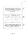
- FIG. 3 is a flowchart illustrating a method for increasing the efficiency of transferring packet of isochronous transfer type in USB 3.0.
- FIG. 4 is a diagram illustrating the transmitting end not being required to re-transmit a packet of isochronous transfer type when the header of the packet is incorrect according to the present invention.
- FIG. 5 is a flowchart illustrating a method for increasing efficiency of transferring packet of isochronous transfer type in USB 3.0 according to a second embodiment of the present invention.
- FIG. 6 is a diagram illustrating the transmitting end not re-transmitting the packet previously transmitted under the condition that the receiving end requires the transmitting end to re-transmit the packet of isochronous transfer type previously transmitted by the transmitting end.
- FIG. 7 is a diagram illustrating an apparatus for sending data on an isochronous communication protocol according to the present invention.
- the present invention provides a novel transmitting method for improving the discontinuous condition and the un-synchronization for the isochronous transfer and further increasing the efficiency of transferring packet of isochronous transfer type.
- FIG. 3 is a flowchart illustrating a method 300 for increasing the efficiency of transferring packet of isochronous transfer type in USB 3.0.
- the transmitting end T is about to transmit two packets DP 1 and DP 2 of isochronous transfer type, and the transferring sequence for the packets is that the transmitting end T transmits the packet DP 1 to the receiving end R first, and then transmits the packet DP 2 to the receiving end R.
- the steps are described as follows:
- Step 301 The receiving end R receives the packet DP 1 of isochronous transfer type transmitted from the transmitting end T;
- Step 302 The receiving end R executes error code checking on the header H 1 of the packet DP 1 of isochronous transfer type according to the link command word error check code CRC L1 and the header error check code CRC H1 of the packet DP 1 of isochronous transfer type for obtaining a link command word check result E L1 and a header check result E H1 respectively;
- Step 303 The receiving end R determines if the header H 1 of the packet DP 1 is correct according to the link command word check result E L1 and the header check result E H1 ; if so, go to step 304 ; if not, go to step 305 ;
- Step 304 The receiving end R accepts the packet DP 1 of isochronous transfer type for executing the following process
- Step 305 The receiving end R ignores the packet DP 1 of isochronous transfer type and does not require the transmitting end T to transmit the packet DP 1 of isochronous transfer type again so as to allow the transmitting end T to transmit the next packet DP 2 of isochronous transfer type.
- steps 301 ⁇ 305 above-mentioned can be executed in the data link layer DL of the receiving end R.
- the packet DP 1 when the packet DP 1 is received from the transmitting end T, the packet DP 1 can be determined to be isochronous transfer type according to the type information TP 1 and the end point information EP 1 of the packet DP 1 .
- the error check code CRC H1 of the header H 1 of the packet DP 1 may be Cyclic Redundancy Check 16 (CRC-16), and the error check code CRC L1 may be CRC- 5 .
- the way to determine if the header H 1 of the packet DP 1 is correct can be executing CRC respectively on the header H 1 and the link command word LW 1 of the packet DP 1 .
- the overall CRC of the header H 1 is to divide the header H 1 (including the error check code CRC H1 ) of the packet DP 1 by a predetermined divisor CRC DH for obtaining a corresponding remainder CRC RH1 .
- the header check result E H1 is obtained according to the remainder CRC RH1 , and the link command word check result E L1 can be obtained similarly.
- the header check result E H1 represents the header H 1 of the packet DP 1 is correct; when the remainder CRC RH1 does not equal the predetermined value X, the header check result E H1 represents the header H 1 of the packet DP 1 is incorrect.
- the predetermined value X is 0; when the remainder CRCR H1 equals 0, the header check result E H1 represents the header H 1 of the packet DP 1 is correct; when the remainder CRCR H1 does not equal 0, the header check result E H1 represents the header H 1 of the packet DP 1 is incorrect.
- the link command word check result E L1 can be obtained similarly.
- the header H 1 when both the header check result E H1 and the link command word check result E L1 represent correct, the header H 1 is determined to be correct; when one of the header check result E H1 and the link command word check result E L1 represents incorrect, the header H 1 is determined to be incorrect.
- the packet DP 1 is uploaded to the protocol layer PR for the following process and the following process in the protocol layer PR is similar to the description above and will not be repeated again for brevity.
- the receiving end R is informed that the packet DP 1 is incorrect by the header check result E H1 and the link command word check result E L1 , and accordingly ignores the packet DP 1 .
- the receiving end R does not require the transmitting end T to transmit the packet DP 1 again, which means the data link layer DL of the receiving end R does not send the retry signal S RETRY , requiring the transmitting end T to transmit the packet DP 1 again, to the transmitting end T.
- the transmitting end T will transmit the packet DP 1 for the second time, which delays the moment that the next packet DP 2 is sent, and consequently the discontinuous condition or the un-synchronization arises.
- the transmitting end T since in the step 305 of the present invention, the transmitting end T is not required to transmit the packet DP 1 again, the next packet DP 2 can be instantly transmitted to the receiving end R, instead of being delayed by the re-transmission for the packet DP 1 , so as to increase the transferring efficiency and improve the discontinuous condition or the un-synchronization for the audio data or the video data.
- FIG. 4 is a diagram illustrating the transmitting end T not being required to re-transmit a packet of isochronous transfer type (step 305 ) when the header of the packet is incorrect according to the present invention.
- the top half of FIG. 4 illustrates the transmitting end T being required to re-transmit a packet of isochronous transfer type when the header of the packet is incorrect (prior art); the bottom half of FIG. 4 illustrates the transmitting end T not being required to re-transmit a packet of isochronous transfer type (step 305 ) when the header of the packet is incorrect according to the present invention.
- the method provided by the present invention can certainly increase the efficiency of transferring packets of isochronous transfer type.
- the transmitting end T is to transmit the packets DP 1 , DP 2 , DP 3 , DP 4 , and DP 5 of isochronous transfer type sequentially.
- the receiving end R receives a packet, in the process of the data link layer, the header of the received packet is executed with error check and accordingly a corresponding acknowledge signal ACK is transmitted to the transmitting end T for informing the transmitting end T that the transmitted packet has been correctly received.
- acknowledge signal ACK represents “LGOOD”, it means the packet transmitted by the transmitting end T is correctly received so the transmitting end T does not have to re-transmit the packet;
- acknowledge signal ACK represents “LBAD”, it means the packet transmitted by the transmitting end T is not correctly received and the transmitting end T has to re-transmit the packet. That is, when the acknowledge signal represents “LBAD”, the receiving end R sends out a retry signal S RETRY for requiring the transmitting end T to re-transmit the packet. It can be seen from the bottom half of FIG. 4 that the packet DP 1 is determined to be incorrect by the process of the data link layer DL of the receiving end R.
- the acknowledge signal ACK 1 corresponding to the packet DP 1 still represents “LGOOD”, so for the transmitting end T, it seems that the transmission of the packet DP 1 is successful and thus a next packet DP 2 is to be transmitted by the transmitting end T consecutively. Furthermore, the receiving end R is informed by the error check that the packet DP 1 is incorrect so that actually the receiving end R does not execute the following process for the packet DP 1 . Instead, the packet DP 1 is ignored. On the other hand, from the top half of FIG. 4 , it can be seen that the packet DP 1 is determined to be incorrect by the process of the data link layer DL of the receiving end R.
- the acknowledge signal ACK 1 corresponding to the packet DP 1 represents “LBAD” to inform the transmitting end T that a re-transmission of the packet DP 1 is required.
- the packet DP 1 from the transmission for the second time is still determined to be incorrect by the process of the data link layer DL of the receiving end R, and the acknowledge signal ACK 2 corresponding to the packet DP 1 , from the transmission for the second time still represents “LBAD” to inform the transmitting end T that the re-transmission for the packet DP 1 is still required.
- the receiving end R receives a correct packet DP 1 till the transmitting end T transmits the packet DP 1 for the third time and accordingly responds an acknowledge signal ACK 3 to the transmitting end T so that the transmitting end T can transmit the next packet DP 2 .
- five packets DP 1 ⁇ DP 3 shown in the bottom half of FIG. 4 are completely transmitted, but only three packet DP 1 ⁇ DP 3 are transmitted shown in the top half of FIG. 4 .
- the packet DP 1 is received incorrectly by the receiving end R in the bottom half of FIG. 4 , it is allowable for the audio or video transmissions and consequently the transmission efficiency is increased.
- the packets received are all correct in the top half of FIG. 4 , however, the transmission efficiency is decreased because of the re-transmission, which possibly causes un-synchronization between the transmitting end T and the receiving end R, causing great inconvenience.
- the transmitting end T comprises a packet transmitting counter C T for counting the number N T of transmitted packets so as to write a correct value in the header sequence number HSEQ;
- the receiving end R comprises a packet receiving counter CR for counting the number N R of received packets so as to determine if the header sequence number of the received packet DP is correct.
- the transmitting end T synchronizes the number N T of the transmitted packets of the transmitting end T and the number N R of the received packets of the receiving end R.
- the transmitting end T resets the number N T of the transmitted packets to be a predetermined value N 1 and sends out a synchronous sequence signal S SEQ to the receiving end R so as to reset the number N R of the received packets of the receiving end R to be the predetermined value N 1 .
- the receiving end R is informed that each time the receiving end R receives a packet correctly, the number N R of the received packets is increased with a step number N STEP .
- the transmitting end T receives an acknowledge signal ACK representing “LGOOD” (meaning the receiving end R has correctly received the packet)
- the number N T of the transmitted packets is increased with the step number N STEP as well.
- the transmitting end T when the transmitting end T is to transmit a first packet DP 0 , the transmitting end T sets the header sequence number HSEQ 0 to be N 1 according to the value of the number N T of the transmitted packets.
- the receiving end R compares the value (N 1 ) of the header sequence number H SEQ0 with the value (N 1 ) of the number N R of the received packets. If the value of the header sequence number HSEQ 0 equals the value of the number N R of the received packets (N 1 ), the receiving end R determines the packet sequence of the packet DP 0 to be correct; if not, the receiving end R determines the packet sequence of the packet DP 0 to be incorrect.
- the receiving end R After the receiving end R correctly receives the packet DP 0 , the receiving end R increases the number N R of the received packets with the step number N STEP , which means the value of the number N R of the received packets becomes (N 1 +N STEP ), and then the receiving end R sends out an acknowledge signal ACK representing “LGOOD” to the transmitting end T for the transmitting end T increasing the value of the number N T of the transmitted packets with the step number N STEP .
- the transmitting end T when the transmitting end T is to transmit the following packet DP 1 , of the packet DP 0 , the transmitting end T sets the header sequence number HSEQ 1 of the packet DP 1 to be (N 1 +N STEP ) according to the value of the number NT of the transmitted packets.
- the receiving end R compares the value of the number N R of the received packets with the value of the header sequence number HSEQ 1 for determining if the packet sequence of the packet DP 1 , is correct.
- FIG. 5 is a flowchart illustrating a method for increasing efficiency of transferring packet of isochronous transfer type in USB 3.0 according to a second embodiment of the present invention.
- the transmitting end T is to transmit two packets DP 0 and DP 1 of isochronous transfer type. That is, the buffer of the transmitting end T stores the packets DP 0 and DP 1 waiting to be transmitted, and the sequence for transmission of the packets DP 0 and DP 1 , is that the packet DP 0 is transmitted to the receiving end R first, and then the packet DP 1 is transmitted to the receiving end R.
- the receiving end R when the receiving end R receives the packet DP 0 , the receiving end R determines if the link command word LW 0 or the header H 0 of the received packet DP 0 is incorrect according to the link command word error check code CRC L0 and the header error check code CRC H0 of the packet DP 0 of isochronous transfer type, and accordingly sends out a retry signal S RETRY to the transmitting end T for requiring re-transmission for the packet DP 0 of isochronous transfer type.
- the steps are explained as follows:
- Step 501 The transmitting end T receives a retry signal S RETRY requiring re-transmission for the packet DP 0 of isochronous transfer type from the receiving end R;
- Step 502 The transmitting end T sets the value of the header sequence number HSEQ 1 of the packet DP 1 of isochronous transfer type according to the value of the header sequence number HSEQ 0 of the packet DP 0 ;
- Step 503 The transmitting end T transmits the packet DP 1 of isochronous transfer type and does not transmit the packet DP 0 .
- steps 501 ⁇ 503 are executed in the data link layer DL of the transmitting end T.
- the transmitting end T can be informed by the retry signal S RETRY that the receiving end R does not successfully receive the packet (the packet DP 0 ) previously transmitted by the transmitting end T, and the transmitting end T can be informed by the type information TP 0 and the end point information EP 0 of the packet DP 0 stored in the buffer of the transmitting end T that the packet DP 0 is of isochronous transfer type.
- the transmitting end T since the transmitting end T does not receive the acknowledge signal ACK representing “LGOOD”, the number N T of the transmitted packets of the transmitting end T is not increased with the step number N STEP . More particularly, the value of the number N T of the transmitted packets of the transmitting end T equals the value of the header sequence number HSEQ 0 of the packet DP 0 .
- the transmitting end T sets the value of the header sequence number HSEQ 1 of the packet DP 1 according to the value of the number N T of the transmitted packets (equals the value of the header sequence number HSEQ 0 ). For example, if the value of the header sequence number HSEQ 0 is 0, then the transmitting end T sets the value of the header sequence number HSEQ 1 of the packet DP 1 to be 0.
- the transmitting end T directly transmits the packet DP 1 . Since the value of the header sequence number HSEQ 1 is set to be equal to the value of the header sequence number HSEQ 0 of the packet DP 0 , the value of the number N R of the received packets of the receiving end R still remains to be equal to the value of the header sequence number HSEQ 0 .
- the receiving end R determines the packet sequence of the packet DP 1 to be correct.
- FIG. 6 is a diagram illustrating the transmitting end T not re-transmitting the packet previously transmitted (step 503 ) under the condition that the receiving end R requires the transmitting end T to re-transmit the packet of isochronous transfer type previously transmitted by the transmitting end T.
- the transmitting end T has sent the sequence signal S SEQ to the receiving end R.
- the transmitting end T resets the number N T of the transmitted packets to be the predetermined value N 1 (in FIG. 6 , the predetermined value is 0).
- the receiving end R resets the number N R of the received packets to be the predetermined value N 1 (0) as well.
- the step number N STEP is set to be 1.
- FIG. 6 illustrates the transmitting end T re-transmitting the packet previously transmitted under the condition that the receiving end R requires the transmitting end T to re-transmit the packet of isochronous transfer type previously transmitted by the transmitting end T (prior art); the bottom half of FIG. 6 illustrates the transmitting end T not re-transmitting the packet previously transmitted (step 503 according to the present invention) under the condition that the receiving end R requires the transmitting end T to re-transmit the packet of isochronous transfer type previously transmitted by the transmitting end T.
- the present invention can certainly increase the efficiency of transferring packet of isochronous transfer type in USB 3.0.
- the transmitting end T is to transmit the packets DP 0 , DP 1 , DP 2 , DP 3 , and DP 4 sequentially, and the packet DP 1 is determined to be incorrect during the process of the data link layer DL of the receiving end R.
- the number N R of the received packets of the receiving end R still remains to be 1, and the receiving end R sends out an acknowledge signal ACK 1 (corresponding to the packet DP 1 ) representing “LBAD” for requiring the transmitting end T to re-transmit. Consequently, the number N T of the transmitted packets of the transmitting end T still remains to be 1 as well.
- ACK 1 acknowledge signal
- the transmitting end T re-transmits the packet DP 1 ; however, in the bottom half of FIG. 6 , the transmitting end T does not re-transmit the packet DP 1 . Instead, the transmitting end T sets the value of the header sequence number HSEQ 2 of the packet DP 2 according to the current value of the number N T of the transmitted packets (equals to the value of the header sequence number HSEQ 1 ) and transmits the packet DP 2 to the receiving end R.
- the receiving end R determines the packet sequence of the packet DP 2 to be correct according to the value of the number N R of the received packets (equals 1) and the value of the value of the header sequence number HSEQ 2 (equals 1). If the value of the header sequence number HSEQ 2 of the packet DP 2 is not set to be 1, the receiving end R determines that during the transmission a packet with the value of the header sequence number equaling 1 is lost, according to the value of the number N R of the received packets (equals 1) and the value of the header sequence number HSEQ 2 (does not equals 1).
- the receiving end R determines un-synchronous to the transmitting end T and consequently sends out a synchronous request signal S SYN to the transmitting end T for requesting synchronization.
- the receiving end R correctly receives the packet DP 2 , and increases the value of the number N R of the received packets (equals 1) with the step number N STEP so that the value of the number N R of the received packets becomes 2.
- the receiving end R sends out an acknowledge signal ACK 2 (corresponding to the packet DP 2 ) representing “LGOOD”.
- the transmitting end T increases the value of the number N T of the transmitted packets with the step number N STEP so that the value of the number N T of the transmitted packets becomes 2.
- the transmitting end T sets the header sequence number HSEQ 3 with the correct value, which allows the receiving end R to determine the packet sequence to be correct and not to send out the synchronous request signal S SYN .
- five packets DP 0 ⁇ DP 4 are completely transmitted as shown in the bottom half of FIG.
- FIG. 7 is a diagram illustrating an apparatus 700 for sending data on an isochronous communication protocol according to the present invention.
- the apparatus 700 is utilized to transmit data.
- the apparatus 700 comprises a first data link layer device 711 , a second data link layer device 712 , a first protocol layer device 721 , and a second protocol layer device 722 .
- the apparatus 700 comprises physical layer devices corresponding to the first and the second data link layer device 711 and 712 (not shown).
- the apparatus 700 is derived from the first and the second embodiments of the present invention. As shown in FIG.
- the first data link layer device 711 and the second data link layer device 712 are both capable of detecting the data transmitted between the two data link layer device 711 and 712 and accordingly generating detecting signals S D1 and S D2 .
- the first data link layer device 711 and the first protocol layer device 721 are in the receiving end, and the second data link layer device 712 and the second protocol layer device 722 are in the transmitting end; when the first data link layer device 711 detects a CRC error in the transmitted packet, the detecting signal S D1 indicates the CRC error and the first data link layer device 711 accordingly transmits a cheating packet data DP CRC to the second data link layer device 712 , wherein the cheating packet data DP CRC comprises the erroneous packet data corresponding to the CRC error.
- the second data link layer device 712 processes the received cheating packet data DP CRC and then transmits to the second protocol layer device 722 .
- the detecting signal S D2 represents that re-transmitting a first packet is required, and the second data link layer device 712 accordingly transmits a cheating packet data DP RETRY to the first data link layer device 711 , wherein the cheating packet data DP RETRY comprises a second packet data which is different from the first packet.
- the first data link layer device 711 processes the received cheating packet data DP RETRY and then transmits to the first protocol layer device 721 .
- the second packet may be a packet following the first packet.
- the receiving end does not send out the retry signal to the transmitting end when a packet of isochronous transfer type with errors exists in the data link layer.
- the present invention provides another method for transmitting, which allows the transmitting end to directly transmit the current packet of isochronous transfer type instead of transmitting the previous packet of isochronous transfer type when the transmitting end receives a retry signal representing that the re-transmission of the previous packet of isochronous transfer type is required, so as for the transmitting end transmitting the successive packets of isochronous transfer type more quickly. In this way, the problem of discontinuous condition or the un-synchronization for isochronous transfer type can be solved, which provides great convenience.
Abstract
Description
Claims (27)
Applications Claiming Priority (3)
| Application Number | Priority Date | Filing Date | Title |
|---|---|---|---|
| TW098116150A TWI423037B (en) | 2009-05-15 | 2009-05-15 | Method for increasing efficiency of transferring packet of isochronous transfer type and device thereof |
| TW98116150A | 2009-05-15 | ||
| TW098116150 | 2009-05-15 |
Publications (2)
| Publication Number | Publication Date |
|---|---|
| US20100293435A1 US20100293435A1 (en) | 2010-11-18 |
| US8473801B2 true US8473801B2 (en) | 2013-06-25 |
Family
ID=43069494
Family Applications (1)
| Application Number | Title | Priority Date | Filing Date |
|---|---|---|---|
| US12/750,666 Active 2032-03-12 US8473801B2 (en) | 2009-05-15 | 2010-03-30 | Method for increasing efficiency of transferring packet of isochronous transfer type and device thereof |
Country Status (2)
| Country | Link |
|---|---|
| US (1) | US8473801B2 (en) |
| TW (1) | TWI423037B (en) |
Families Citing this family (3)
| Publication number | Priority date | Publication date | Assignee | Title |
|---|---|---|---|---|
| US9606955B2 (en) * | 2014-02-10 | 2017-03-28 | Intel Corporation | Embedded universal serial bus solutions |
| JP6232604B2 (en) * | 2014-02-10 | 2017-11-22 | サイレックス・テクノロジー株式会社 | Device server and its control method |
| US10841621B2 (en) * | 2017-03-01 | 2020-11-17 | Wyse Technology L.L.C. | Fault recovery of video bitstream in remote sessions |
Citations (14)
| Publication number | Priority date | Publication date | Assignee | Title |
|---|---|---|---|---|
| US4827339A (en) * | 1986-02-20 | 1989-05-02 | Kokusai Denshin Denwa Co., Ltd. | Moving picture signal transmission system |
| US5774483A (en) * | 1993-05-31 | 1998-06-30 | Samsung Electronics Co., Ltd. | Method and apparatus for recovering an image in a video telephone system |
| US20010025239A1 (en) | 2000-03-02 | 2001-09-27 | Rolf Hakenberg | Data transmission in non-reliable networks |
| US6593937B2 (en) * | 1998-06-18 | 2003-07-15 | Sony Corporation | Method of and apparatus for handling high bandwidth on-screen-display graphics data over a distributed IEEE 1394 network utilizing an isochronous data transmission format |
| US20030169687A1 (en) | 2002-03-05 | 2003-09-11 | Sony Corporation And Sony Electronics, Inc. | Method of flow control for data transported using isochronous packets over an IEEE 1394-2000 serial bus network |
| US6717947B1 (en) * | 1998-12-03 | 2004-04-06 | Lsi Logic Corporation | Method and apparatus for isochronous data transfer with retry capability |
| US7085233B2 (en) * | 2000-10-11 | 2006-08-01 | Matsushita Electric Industrial Co., Ltd. | Communications control method |
| US20060224936A1 (en) | 2005-03-31 | 2006-10-05 | Fujitsu Limited | Data transfer apparatus |
| US20070239900A1 (en) | 2005-12-06 | 2007-10-11 | Avocent Corporation | Universal serial bus (USB) extension |
| CN101094206A (en) | 2007-08-02 | 2007-12-26 | 中兴通讯股份有限公司 | Data transmission device |
| US20100198999A1 (en) * | 2009-02-05 | 2010-08-05 | Qualcomm Incorporated | Method and system for wireless usb transfer of isochronous data using bulk data transfer type |
| US20100287456A1 (en) | 2009-05-07 | 2010-11-11 | Tso-Hsuan Chang | Data transfer method capable of saving memory for storing packet in usb protocol and apparatus thereof |
| CN101887403A (en) | 2010-06-25 | 2010-11-17 | 钰创科技股份有限公司 | Data transmission method and device for saving space of memory used for accessing packet in universal serial bus protocol |
| US8041856B2 (en) * | 2008-09-30 | 2011-10-18 | Lsi Corporation | Skip based control logic for first in first out buffer |
Family Cites Families (2)
| Publication number | Priority date | Publication date | Assignee | Title |
|---|---|---|---|---|
| CN1310163C (en) * | 2002-03-13 | 2007-04-11 | 先进微装置公司 | USB host controller |
| EP2242231A1 (en) * | 2003-11-12 | 2010-10-20 | Qualcomm Incorporated | High data rate interface with improved link control |
-
2009
- 2009-05-15 TW TW098116150A patent/TWI423037B/en active
-
2010
- 2010-03-30 US US12/750,666 patent/US8473801B2/en active Active
Patent Citations (15)
| Publication number | Priority date | Publication date | Assignee | Title |
|---|---|---|---|---|
| US4827339A (en) * | 1986-02-20 | 1989-05-02 | Kokusai Denshin Denwa Co., Ltd. | Moving picture signal transmission system |
| US5774483A (en) * | 1993-05-31 | 1998-06-30 | Samsung Electronics Co., Ltd. | Method and apparatus for recovering an image in a video telephone system |
| US6593937B2 (en) * | 1998-06-18 | 2003-07-15 | Sony Corporation | Method of and apparatus for handling high bandwidth on-screen-display graphics data over a distributed IEEE 1394 network utilizing an isochronous data transmission format |
| US6717947B1 (en) * | 1998-12-03 | 2004-04-06 | Lsi Logic Corporation | Method and apparatus for isochronous data transfer with retry capability |
| US20010025239A1 (en) | 2000-03-02 | 2001-09-27 | Rolf Hakenberg | Data transmission in non-reliable networks |
| US7085233B2 (en) * | 2000-10-11 | 2006-08-01 | Matsushita Electric Industrial Co., Ltd. | Communications control method |
| US20030169687A1 (en) | 2002-03-05 | 2003-09-11 | Sony Corporation And Sony Electronics, Inc. | Method of flow control for data transported using isochronous packets over an IEEE 1394-2000 serial bus network |
| US7929447B2 (en) * | 2002-03-05 | 2011-04-19 | Sony Corporation | Method of flow control for data transported using isochronous packets over an IEEE 1394-2000 serial bus network |
| US20060224936A1 (en) | 2005-03-31 | 2006-10-05 | Fujitsu Limited | Data transfer apparatus |
| US20070239900A1 (en) | 2005-12-06 | 2007-10-11 | Avocent Corporation | Universal serial bus (USB) extension |
| CN101094206A (en) | 2007-08-02 | 2007-12-26 | 中兴通讯股份有限公司 | Data transmission device |
| US8041856B2 (en) * | 2008-09-30 | 2011-10-18 | Lsi Corporation | Skip based control logic for first in first out buffer |
| US20100198999A1 (en) * | 2009-02-05 | 2010-08-05 | Qualcomm Incorporated | Method and system for wireless usb transfer of isochronous data using bulk data transfer type |
| US20100287456A1 (en) | 2009-05-07 | 2010-11-11 | Tso-Hsuan Chang | Data transfer method capable of saving memory for storing packet in usb protocol and apparatus thereof |
| CN101887403A (en) | 2010-06-25 | 2010-11-17 | 钰创科技股份有限公司 | Data transmission method and device for saving space of memory used for accessing packet in universal serial bus protocol |
Also Published As
| Publication number | Publication date |
|---|---|
| US20100293435A1 (en) | 2010-11-18 |
| TWI423037B (en) | 2014-01-11 |
| TW201040739A (en) | 2010-11-16 |
Similar Documents
| Publication | Publication Date | Title |
|---|---|---|
| US20210136126A1 (en) | Transmitting common mode control data over audio return channel | |
| WO2021008248A1 (en) | Data frame reception method and device and communication method and system | |
| US8281189B2 (en) | SATA primitive prediction and correction | |
| TWI442733B (en) | Communication apparatus and system | |
| US20230379085A1 (en) | Method for controlling retransmission in physical layer | |
| US8473801B2 (en) | Method for increasing efficiency of transferring packet of isochronous transfer type and device thereof | |
| JP2017208710A (en) | Communication device, communication method, program, and communication system | |
| JP6787318B2 (en) | Data transmission equipment and data transmission methods, receivers and reception methods, programs, and data transmission systems | |
| US8880972B2 (en) | Serial transmission apparatus, information processing apparatus, and serial transmission method | |
| CN111327393A (en) | Image detector parameter transmission method based on serial communication interface | |
| US8438445B2 (en) | Methods and systems for error detection of data transmission | |
| US20230199306A1 (en) | Communication device and communication system | |
| US20070116066A1 (en) | Method and apparatus for packet error detection | |
| US8780934B2 (en) | Method for performing serial transport communication, and associated device | |
| KR20190008196A (en) | COMMUNICATION DEVICE, COMMUNICATION METHOD, PROGRAM, AND COMMUNICATION SYSTEM | |
| EP1353468B1 (en) | ARQ method with isochronous and asynchronous transmission | |
| US8806291B2 (en) | Data transfer device and control method of data transfer device | |
| CN103001733B (en) | A kind of method promoting the efficiency of transmission packet | |
| CN117527151B (en) | UCIE-based data retransmission method | |
| WO2022193065A1 (en) | Data transmission method and apparatus | |
| CN104660374A (en) | Device for transmitting data in isochronous communication protocol | |
| JPH0973373A (en) | Parallel interface | |
| JPH09326782A (en) | Serial communication method | |
| JP2016096493A (en) | Communication system and image forming device | |
| JP2022182021A (en) | Serial communication device and serial communication method |
Legal Events
| Date | Code | Title | Description |
|---|---|---|---|
| AS | Assignment |
Owner name: ETRON TECHNOLOGY, INC., TAIWAN Free format text: ASSIGNMENT OF ASSIGNORS INTEREST;ASSIGNORS:CHANG, TSO-HSUAN;HSU, MING-HSU;HSIEH, TENG-CHUAN;REEL/FRAME:024163/0861 Effective date: 20100323 |
|
| STCF | Information on status: patent grant |
Free format text: PATENTED CASE |
|
| AS | Assignment |
Owner name: EEVER TECHNOLOGY, INC., TAIWAN Free format text: ASSIGNMENT OF ASSIGNORS INTEREST;ASSIGNOR:ETRON TECHNOLOGY, INC.;REEL/FRAME:037771/0774 Effective date: 20160111 |
|
| FPAY | Fee payment |
Year of fee payment: 4 |
|
| FEPP | Fee payment procedure |
Free format text: PAT HOLDER NO LONGER CLAIMS SMALL ENTITY STATUS, ENTITY STATUS SET TO UNDISCOUNTED (ORIGINAL EVENT CODE: STOL) |
|
| FEPP | Fee payment procedure |
Free format text: ENTITY STATUS SET TO SMALL (ORIGINAL EVENT CODE: SMAL); ENTITY STATUS OF PATENT OWNER: SMALL ENTITY |
|
| MAFP | Maintenance fee payment |
Free format text: PAYMENT OF MAINTENANCE FEE, 8TH YR, SMALL ENTITY (ORIGINAL EVENT CODE: M2552); ENTITY STATUS OF PATENT OWNER: SMALL ENTITY Year of fee payment: 8 |