US8514547B2 - Volumetrically efficient wet electrolytic capacitor - Google Patents
Volumetrically efficient wet electrolytic capacitor Download PDFInfo
- Publication number
- US8514547B2 US8514547B2 US12/916,788 US91678810A US8514547B2 US 8514547 B2 US8514547 B2 US 8514547B2 US 91678810 A US91678810 A US 91678810A US 8514547 B2 US8514547 B2 US 8514547B2
- Authority
- US
- United States
- Prior art keywords
- anode
- electrolytic capacitor
- acid
- wet electrolytic
- interior space
- Prior art date
- Legal status (The legal status is an assumption and is not a legal conclusion. Google has not performed a legal analysis and makes no representation as to the accuracy of the status listed.)
- Active, expires
Links
Images


Classifications
-
- H—ELECTRICITY
- H01—ELECTRIC ELEMENTS
- H01G—CAPACITORS; CAPACITORS, RECTIFIERS, DETECTORS, SWITCHING DEVICES OR LIGHT-SENSITIVE DEVICES, OF THE ELECTROLYTIC TYPE
- H01G9/00—Electrolytic capacitors, rectifiers, detectors, switching devices, light-sensitive or temperature-sensitive devices; Processes of their manufacture
- H01G9/145—Liquid electrolytic capacitors
-
- H—ELECTRICITY
- H01—ELECTRIC ELEMENTS
- H01G—CAPACITORS; CAPACITORS, RECTIFIERS, DETECTORS, SWITCHING DEVICES OR LIGHT-SENSITIVE DEVICES, OF THE ELECTROLYTIC TYPE
- H01G9/00—Electrolytic capacitors, rectifiers, detectors, switching devices, light-sensitive or temperature-sensitive devices; Processes of their manufacture
- H01G9/004—Details
- H01G9/04—Electrodes or formation of dielectric layers thereon
- H01G9/06—Mounting in containers
-
- H—ELECTRICITY
- H01—ELECTRIC ELEMENTS
- H01G—CAPACITORS; CAPACITORS, RECTIFIERS, DETECTORS, SWITCHING DEVICES OR LIGHT-SENSITIVE DEVICES, OF THE ELECTROLYTIC TYPE
- H01G9/00—Electrolytic capacitors, rectifiers, detectors, switching devices, light-sensitive or temperature-sensitive devices; Processes of their manufacture
- H01G9/004—Details
- H01G9/04—Electrodes or formation of dielectric layers thereon
- H01G9/042—Electrodes or formation of dielectric layers thereon characterised by the material
- H01G9/0425—Electrodes or formation of dielectric layers thereon characterised by the material specially adapted for cathode
-
- H—ELECTRICITY
- H01—ELECTRIC ELEMENTS
- H01G—CAPACITORS; CAPACITORS, RECTIFIERS, DETECTORS, SWITCHING DEVICES OR LIGHT-SENSITIVE DEVICES, OF THE ELECTROLYTIC TYPE
- H01G9/00—Electrolytic capacitors, rectifiers, detectors, switching devices, light-sensitive or temperature-sensitive devices; Processes of their manufacture
- H01G9/004—Details
- H01G9/04—Electrodes or formation of dielectric layers thereon
- H01G9/048—Electrodes or formation of dielectric layers thereon characterised by their structure
- H01G9/052—Sintered electrodes
-
- Y—GENERAL TAGGING OF NEW TECHNOLOGICAL DEVELOPMENTS; GENERAL TAGGING OF CROSS-SECTIONAL TECHNOLOGIES SPANNING OVER SEVERAL SECTIONS OF THE IPC; TECHNICAL SUBJECTS COVERED BY FORMER USPC CROSS-REFERENCE ART COLLECTIONS [XRACs] AND DIGESTS
- Y10—TECHNICAL SUBJECTS COVERED BY FORMER USPC
- Y10T—TECHNICAL SUBJECTS COVERED BY FORMER US CLASSIFICATION
- Y10T29/00—Metal working
- Y10T29/43—Electric condenser making
Definitions
- Electrolytic capacitors are increasingly being used in the design of circuits due to their volumetric efficiency, reliability, and process compatibility. Typically, electrolytic capacitors have a larger capacitance per unit volume than certain other types of capacitors, making electrolytic capacitors valuable in relatively high-current and low-frequency electrical circuits.
- One type of capacitor that has been developed is a wet electrolytic capacitor that includes an anode, a cathode, and a liquid or “wet” working electrolyte.
- Wet electrolytic capacitors tend to offer a good combination of high capacitance with low leakage current.
- wet electrolytic capacitors may exhibit advantages over solid electrolytic capacitors. For example, wet electrolytic capacitors may, in certain situations, operate at a higher working voltage than solid electrolytic capacitors. Additionally, by way of example, wet electrolytic capacitors may be much larger in size than solid electrolytic capacitors, leading to larger capacitances for such large wet electrolytic capacitors.
- the anode may be a metal foil (e.g., aluminum foil). Because the electrostatic capacitance of the capacitor is proportional to its electrode area, the surface of the metallic foil may be, prior to the formation of the dielectric film, roughened or subjected to a chemical conversion to increase its effective area. This step of roughening the surface of the metallic foil is called etching. Etching is normally carried out either by the method (chemical etching) of conducting immersion into a solution of hydrochloric acid or by the method (electrochemical etching) of carrying out electrolysis in an aqueous solution of hydrochloric acid.
- etching is normally carried out either by the method (chemical etching) of conducting immersion into a solution of hydrochloric acid or by the method (electrochemical etching) of carrying out electrolysis in an aqueous solution of hydrochloric acid.
- the capacitance of the electrolytic capacitor is determined by the extent of roughing (the surface area) of the anode foil and the thickness and the dielectric constant of the oxide film. Due to the limited surface area that may be provided by etching metallic foils, attempts have also been made to employ porous sintered bodies, also called “slugs”, in wet electrolytic capacitors.
- a tantalum slug may be formed by mixing powdered tantalum particles with a suitable binder/lubricant to ensure that the particles will adhere to each other when pressed to form the anode. The powdered tantalum is compressed under high pressure around a tantalum wire and is sintered at high temperature under vacuum to form a sponge-like structure, which is highly porous and provides a large internal surface area.
- a wet electrolytic capacitor comprising a metal casing that contains a first edge portion and an opposing second edge portion extending in a longitudinal direction from an end portion to define an interior space.
- An electrochemically active cathode material is disposed on at least a portion of an interior surface of the metal casing.
- the capacitor further comprises an anode formed from an anodically oxidized, sintered porous body.
- the anode contains an upper end portion and a lower end portion, wherein a first edge portion and an opposing second edge portion extend in the longitudinal direction between the upper end portion and the lower end portion to define a length of the anode.
- the anode further has a width defined between the first edge portion and the second edge portion of the anode.
- the ratio of the width of the anode to the width of the interior space is from about 0.80 to 1.00.
- the anode is positioned within and occupies about 70 vol. % or more of the interior space defined by the metal casing.
- the capacitor also comprises a liquid electrolyte that is in electrical contact with the anode and the electrochemically active material.
- a method for forming a wet electrolytic capacitor comprises compacting a powder that includes tantalum, niobium, or an electrically conductive oxide thereof to form a porous body, wherein an anode lead extends from the porous body.
- the porous body is sintered within a heat treatment device without physically contacting a surface of the porous body with an external surface.
- the sintered, porous body is anodically oxidized to form an anode having a length of from about 1 to about 60 millimeters and a width of from about 1 to about 40 millimeters.
- the anode is inserted into an interior space of a metal casing, wherein at least a portion of an interior surface of the metal casing is coated with an electrochemically active material.
- the anode and the electrochemically active material are contacted with a liquid electrolyte.
- FIG. 1 is a cross-sectional view of an anode surrounded by a separator for use in one embodiment of the wet electrolytic capacitor of the present invention
- FIG. 2 is a cross-sectional view of one embodiment of a casing coated with an electrochemically active cathode material that may be used in the present invention
- FIG. 3 shows the anode of FIG. 1 positioned within the casing of FIG. 2 ;
- FIG. 4 is a cross-sectional view of the anode/casing assembly of FIG. 3 in combination with a liquid seal;
- FIG. 5 is a cross-sectional view of one embodiment of a sealed lid assembly that may be used in the present invention.
- FIG. 6 shows the lid assembly of FIG. 5 positioned over the casing of FIG. 4 ;
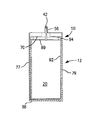
- FIG. 7 is a cross-sectional view of one embodiment of a wet electrolytic capacitor of the present invention.
- FIG. 8 is a cross-sectional view of a sintered anode body that may be employed in one embodiment of the present invention.
- FIGS. 9-10 schematically illustrate one embodiment of a sintering method that may be employed in the present invention.
- the present invention is directed to a wet electrolytic capacitor that contains an anode positioned with an interior space of a metal casing.
- the anode and metal casing are of a size such that the anode occupies a substantial portion of the volume of the interior space. More particularly, the anode occupies about 70 vol. % or more, in some embodiments about 75 vol. % or more, in some embodiments from about 80 vol. % to about 98 vol. %, and in some embodiments, from about 85 vol. % to 97 vol. % of the interior space.
- the use of an anode that occupies such a large portion of the interior space enhances the volumetric efficiency (capacitance*voltage per volume) of the resulting capacitor.
- the volumetric efficiency may, for example, range from about 10,000 ⁇ F*V/cm 3 to about 150,000 ⁇ F/cm 3 , in some embodiments from about 15,000 ⁇ F*V/cm 3 to about 100,000 ⁇ F*V/cm 3 , and in some embodiments, from about 20,000 p F *V/cm 3 to about 95,000 ⁇ F*V/cm 3 .
- Volumetric efficiency is determined by multiplying the rated voltage of a part by its capacitance, and then dividing by the product by the volume of the part. For example, a rating may be 50 volts for a part having a capacitance of 1800 ⁇ F, which results in a product of 90,000 ⁇ F*V. If the part occupies a volume of about 2 cm 3 , this results in a volumetric efficiency of about 45,000 ⁇ F*V/cm 3 .
- an anode that has a size large enough to occupy a substantial portion of the interior of a metal casing is facilitated by optimizing the dimensional stability of the anode. More specifically, the present inventors have discovered that selective control over the materials and method from which the anode is made can allow it to remain dimensionally stable even after sintering.
- the anode contains a porous body formed from a valve metal powder.
- the specific charge of the powder may vary, such as from about 2,000 ⁇ F*V/g to about 80,000 ⁇ F*V/g, in some embodiments from about 5,000 ⁇ F*V/g to about 40,000 ⁇ F*V/g or more, and in some embodiments, from about 10,000 to about 20,000 ⁇ F*V/g.
- the valve metal powder contains a valve metal (i.e., metal that is capable of oxidation) or valve metal-based compound, such as tantalum, niobium, aluminum, hafnium, titanium, alloys thereof, oxides thereof, nitrides thereof, and so forth.
- the valve metal composition may contain an electrically conductive oxide of niobium, such as niobium oxide having an atomic ratio of niobium to oxygen of 1:1.0 ⁇ 1.0, in some embodiments 1:1.0 ⁇ 0.3, in some embodiments 1:1.0 ⁇ 0.1, and in some embodiments, 1:1.0 ⁇ 0.05.
- the niobium oxide may be NbO 0.7 , NbO 1.0 , NbO 1.1 , and NbO 2 . Examples of such valve metal oxides are described in U.S. Pat. No. 6,322,912 to Fife; U.S. Pat. No. 6,391,275 to Fife et al.; U.S. Pat. No.
- the particles of the powder may be flaked, angular, nodular, and mixtures or variations thereof.
- the particles also typically have a screen size distribution of at least about 60 mesh, in some embodiments from about 60 to about 325 mesh, and in some embodiments, from about 100 to about 200 mesh.
- the specific surface area is from about 0.1 to about 10.0 m 2 /g, in some embodiments from about 0.5 to about 5.0 m 2 /g, and in some embodiments, from about 1.0 to about 2.0 m 2 /g.
- the term “specific surface area” refers to the surface area determined by the physical gas adsorption (B.E.T.) method of Bruanauer, Emmet, and Teller, Journal of American Chemical Society, Vol. 60, 1938, p.
- the bulk (or Scott) density is typically from about 0.1 to about 5.0 g/cm 3 , in some embodiments from about 0.2 to about 4.0 g/cm 3 , and in some embodiments, from about 0.5 to about 3.0 g/cm 3 .
- a binder and/or lubricant may be employed to ensure that the particles adequately adhere to each other when pressed to form the anode body.
- Suitable binders may include camphor, stearic and other soapy fatty acids, Carbowax (Union Carbide), Glyptal (General Electric), polyvinyl alcohols, naphthalene, vegetable wax, and microwaxes (purified paraffins).
- the binder may be dissolved and dispersed in a solvent. Exemplary solvents may include water, alcohols, and so forth.
- the percentage of binders and/or lubricants may vary from about 0.1% to about 8% by weight of the total mass. It should be understood, however, that binders and lubricants are not required in the present invention.
- the resulting powder may be compacted using any conventional powder press mold.
- the press mold may be a single station compaction press using a die and one or multiple punches.
- anvil-type compaction press molds may be used that use only a die and single lower punch.
- Single station compaction press molds are available in several basic types, such as cam, toggle/knuckle and eccentric/crank presses with varying capabilities, such as single action, double action, floating die, movable platen, opposed ram, screw, impact, hot pressing, coining or sizing.
- the resulting anode body may then be diced into any desired shape, such as square, rectangle, circle, oval, triangle, hexagon, octagon, heptagon, pentagon, etc.
- the anode body may also have a “fluted” shape in that it contains one or more furrows, grooves, depressions, or indentations to increase the surface to volume ratio to minimize ESR and extend the frequency response of the capacitance.
- the anode body may then be subjected to a heating step in which most, if not all, of any binder/lubricant are removed.
- the anode body is typically heated by an oven that operates at a temperature of from about 150° C. to about 500° C.
- the binder/lubricant may also be removed by contacting the pellet with an aqueous solution, such as described in U.S. Pat. No. 6,197,252 to Bishop, et al.
- the anode body is then sintered.
- the temperature, atmosphere, and time of the sintering may depend on a variety of factors, such as the type of anode, the size of the anode, etc.
- sintering occurs at a temperature of from about from about 800° C. to about 1900° C., in some embodiments from about 1000° C. to about 1500° C., and in some embodiments, from about 1100° C. to about 1400° C., for a time of from about 5 minutes to about 100 minutes, and in some embodiments, from about 30 minutes to about 60 minutes.
- sintering may occur in an atmosphere that limits the transfer of oxygen atoms to the anode.
- sintering may occur in a reducing atmosphere, such as in a vacuum, inert gas, hydrogen, etc.
- the reducing atmosphere may be at a pressure of from about 10 Torr to about 2000 Torr, in some embodiments from about 100 Torr to about 1000 Torr, and in some embodiments, from about 100 Torr to about 930 Torr.
- Mixtures of hydrogen and other gases e.g., argon or nitrogen may also be employed.
- This shrinkage differential can, in turn, cause the anode body to bend and form a curved shape (e.g., crescent shape).
- a curved shape e.g., crescent shape
- the present inventors have discovered that sintering may be performed in such a manner that the surfaces of the anode body are not in physical contact with an external surface (e.g., surface of a sintering tray).
- FIGS. 9-10 for example, one embodiment of such a sintering technique is shown in which one or more anodes 20 are connected to a stringer 200 via an anode lead 42 .
- Any known method may be employed to attach the anode lead 42 to the stringer 200 , such as welding, swaging, etc.
- the anodes 20 are able to “hang” from the stringer 200 without physically contacting an external surface.
- the resulting anode assembly 201 may thus be positioned on a surface 221 that passes through a heat treatment device or furnace 220 ( FIG. 10 ). As the anodes 20 are heated in the furnace 220 , they are allowed to shrink freely without physical constraint.
- a hanging anode may be vertically displaced into a furnace and then lifted out of the device upon completion of the sintering process.
- anode 20 may thus remain dimensionally stable in that it possesses only a small degree of curvature, if any.
- the dimensional stability may be characterized by the orientation of the anode relative to a longitudinal medial plane that extends through an end of the anode.
- FIG. 8 for example, one embodiment of an anode 20 is shown that extends in the direction of a longitudinal axis 3 .
- the anode 20 has an upper end portion 17 and lower end portion 19 between which extends a first edge portion 7 and an opposing second edge portion 9 .
- a medial longitudinal plane 13 extends through the upper end portion 17 in a direction parallel to the longitudinal axis 3 .
- the anode 20 Due to its dimensional stability, the anode 20 possesses only a small surface variance, if any, between the medial plane 13 and respective edge portions 7 and 9 . That is, the difference “W” between the distance “a” (between the medial plane 13 and the edge portion 7 ) and the distance “b” (between the medial plane 13 and the edge portion 9 ), also known as “warp”, is generally small along the length of the anode 20 .
- the difference W may be about 0.25 millimeters or less, in some embodiments about 0.20 millimeters or less, in some embodiments about 0.15 millimeters or less, and in some embodiments, from 0 to about 0.10 millimeters, along the length of the anode 20 , such as at the center of the anode as shown in FIG. 8 .
- the radius of curvature which is inversely proportional to the degree of curvature, may also be used to define the dimensionally stable anode 20 .
- the radius of curvature in the direction of the medial transverse plane 14 may be about 25 centimeters or greater, in some embodiments about 50 centimeters or greater, and in some embodiments, about 100 centimeters or greater.
- the anode is also coated with a dielectric.
- the dielectric may be formed by anodically oxidizing (“anodizing”) the sintered anode so that a dielectric layer is formed over and/or within the anode.
- anodizing anodically oxidizing
- a tantalum (Ta) anode may be anodized to tantalum pentoxide (Ta 2 O 5 ).
- anodization is performed by initially applying a solution to the anode, such as by dipping anode into the electrolyte.
- a solvent is generally employed, such as water (e.g., deionized water).
- a compound may be employed that is capable of dissociating in the solvent to form ions.
- an acid e.g., phosphoric acid
- an acid may constitute from about 0.01 wt. % to about 5 wt. %, in some embodiments from about 0.05 wt. % to about 0.8 wt. %, and in some embodiments, from about 0.1 wt. % to about 0.5 wt. % of the anodizing solution.
- blends of acids may also be employed.
- a current is passed through the anodizing solution to form the dielectric layer.
- the value of the formation voltage manages the thickness of the dielectric layer.
- the power supply may be initially set up at a galvanostatic mode until the required voltage is reached. Thereafter, the power supply may be switched to a potentiostatic mode to ensure that the desired dielectric thickness is formed over the entire surface of the anode.
- a potentiostatic mode to ensure that the desired dielectric thickness is formed over the entire surface of the anode.
- other known methods may also be employed, such as pulse or step potentiostatic methods.
- the voltage at which anodic oxidation occurs typically ranges from about 4 to about 250 V, and in some embodiments, from about 9 to about 200 V, and in some embodiments, from about 20 to about 150 V.
- the anodizing solution can be kept at an elevated temperature, such as about 30° C. or more, in some embodiments from about 40° C. to about 200° C., and in some embodiments, from about 50° C. to about 100° C.
- Anodic oxidation can also be done at ambient temperature or lower.
- the resulting dielectric layer may be formed on a surface of the anode and within its pores.
- FIGS. 1-6 illustrate one particular embodiment of a method for forming a capacitor 10 in accordance with the present invention.
- an anode 20 that may be employed in the present invention is shown.
- the anode 20 is formed from a sintered, porous body that is coated with a dielectric (not shown).
- the anode 20 may have any desired shape, such as cylindrical, D-shaped, rectangular, triangular, prismatic, etc.
- An anode lead 42 (e.g., wire, sheet, etc.) is electrically connected to the anode 20 . Electrical contact with the anode 20 may be accomplished by in a variety of ways, such as by coupling the lead 42 using resistance or laser welding.
- the lead 42 may be embedded into the anode body during its formation (e.g., prior to sintering).
- the lead 42 is typically formed from any electrically conductive material, such as tantalum, niobium, nickel, aluminum, hafnium, titanium, etc., as well as oxides and/or nitrides of thereof.
- the anode 20 may initially be impregnated with an electrolyte (not shown) before being positioned within the casing.
- the electrolyte may also be added to the capacitor at a later stage of production.
- the electrolyte is the material that provides the connecting path between the anode and cathode.
- Various suitable electrolytes are described in U.S. Pat. Nos. 5,369,547 and 6,594,140 to Evans, et al., which are incorporated herein their entirety by reference thereto for all purposes.
- the electrolyte is ionically conductive in that has an ionic conductivity of from about 0.5 to about 100 milliSiemens per centimeter (“mS/cm”), in some embodiments from about 1 to about 80 mS/cm, in some embodiments from about 5 mS/cm to about 60 mS/cm, and in some embodiments, from about 10 to about 40 mS/cm, determined at a temperature of 25° C. using any known electric conductivity meter (e.g., Oakton Con Series 11). Within the ranges noted above, it is believed that the ionic conductivity of the electrolyte allows the electric field to extend into the electrolyte to a length (Debye length) sufficient to result in significant charge separation.
- mS/cm milliSiemens per centimeter
- the capacitor may be charged to a voltage that exceeds the formation voltage of the dielectric.
- the ratio of the voltage to which the capacitor can be charged to the formation voltage may, for instance, be from about 1.0 to 2.0, in some embodiments from about 1.1 to about 1.8, and in some embodiments, from about 1.2 to about 1.6.
- the voltage to which the capacitor is charged may be from about 200 to about 350 V, in some embodiments from about 220 to about 320 V, and in some embodiments, from about 250 to about 300V.
- the electrolyte is generally in the form of a liquid, such as a solution (e.g., aqueous or non-aqueous), dispersion, gel, etc.
- the electrolyte may be an aqueous solution of an acid (e.g., sulfuric acid, phosphoric acid, or nitric acid), base (e.g., potassium hydroxide), or salt (e.g., ammonium salt, such as a nitrate), as well any other suitable electrolyte known in the art, such as a salt dissolved in an organic solvent (e.g., ammonium salt dissolved in a glycol-based solution).
- an organic solvent e.g., ammonium salt dissolved in a glycol-based solution.
- the desired ionic conductivity may be achieved by selecting ionic compound(s) (e.g., acids, bases, salts, and so forth) within certain concentration ranges.
- ionic compound(s) e.g., acids, bases, salts, and so forth
- salts of weak organic acids may be effective in achieving the desired conductivity of the electrolyte.
- the cation of the salt may include monatomic cations, such as alkali metals (e.g., Li + , Na + , K + , Rb + , or Cs + ), alkaline earth metals (e.g., Be 2+ , Mg 2+ , Ca 2+ , Sr 2+ or Ba 2+ ), transition metals (e.g., Ag + , Fe 2+ , Fe 3+ , etc.), as well as polyatomic cations, such as NH 4 + .
- alkali metals e.g., Li + , Na + , K + , Rb + , or Cs +
- alkaline earth metals e.g., Be 2+ , Mg 2+ , Ca 2+ , Sr 2+ or Ba 2+
- transition metals e.g., Ag + , Fe 2+ , Fe 3+ , etc.
- polyatomic cations such as NH 4 + .
- the organic acid used to form the anion of the salt is “weak” in the sense that it typically has a first acid dissociation constant (pK a1 ) of about 0 to about 11, in some embodiments about 1 to about 10, and in some embodiments, from about 2 to about 10, determined at 25° C.
- pK a1 first acid dissociation constant
- Any suitable weak organic acids may be used in the present invention, such as carboxylic acids, such as acrylic acid, methacrylic acid, malonic acid, succinic acid, salicylic acid, sulfosalicylic acid, adipic acid, maleic acid, malic acid, oleic acid, gallic acid, tartaric acid (e.g., dextotartaric acid, mesotartaric acid, etc.), citric acid, formic acid, acetic acid, glycolic acid, oxalic acid, propionic acid, phthalic acid, isophthalic acid, glutaric acid, gluconic acid, lactic acid, aspartic acid, glutaminic acid, itaconic acid, trifluoroacetic acid, barbituric acid, cinnamic acid, benzoic acid, 4-hydroxybenzoic acid, aminobenzoic acid, etc.; blends thereof, and so forth.
- carboxylic acids such as acrylic acid, methacrylic acid, malonic acid, succin
- Polyprotic acids are particularly desirable for use in forming the salt, such as adipic acid (pK a1 of 4.43 and pK a2 of 5.41), ⁇ -tartaric acid (pK a1 of 2.98 and pK a2 of 4.34), meso-tartaric acid (pK a1 of 3.22 and pK a2 of 4.82), oxalic acid (pK a1 of 1.23 and pK a2 of 4.19), lactic acid (pK a1 of 3.13, pK a2 of 4.76, and pK a3 of 6.40), etc.
- adipic acid pK a1 of 4.43 and pK a2 of 5.41
- ⁇ -tartaric acid pK a1 of 2.98 and pK a2 of 4.34
- meso-tartaric acid pK a1 of 3.22 and pK a2 of 4.82
- oxalic acid pK
- such weak organic acid salts are typically present in the electrolyte in an amount of from about 0.1 to about 25 wt. %, in some embodiments from about 0.2 to about 20 wt. %, in some embodiments from about 0.3 to about 15 wt. %, and in some embodiments, from about 0.5 to about 5 wt. %.
- the electrolyte is typically aqueous in that it contains an aqueous solvent, such as water (e.g., deionized water).
- water e.g., deionized water
- water may constitute from about 20 wt. % to about 95 wt. %, in some embodiments from about 30 wt. % to about 90 wt. %, and in some embodiments, from about 40 wt. % to about 85 wt. % of the electrolyte.
- a secondary solvent may also be employed to form a solvent mixture.
- Suitable secondary solvents may include, for instance, glycols (e.g., ethylene glycol, propylene glycol, butylene glycol, triethylene glycol, hexylene glycol, polyethylene glycols, ethoxydiglycol, dipropyleneglycol, etc.); glycol ethers (e.g., methyl glycol ether, ethyl glycol ether, isopropyl glycol ether, etc.); alcohols (e.g., methanol, ethanol, n-propanol, iso-propanol, and butanol); ketones (e.g., acetone, methyl ethyl ketone, and methyl isobutyl ketone); esters (e.g., ethyl acetate, butyl acetate, diethylene glycol ether acetate, methoxypropyl acetate, ethylene carbonate, propylene carbonate, etc.); amides (e.g.
- Such solvent mixtures typically contain water in an amount from about 40 wt. % to about 80 wt. %, in some embodiments from about 50 wt. % to about 75 wt. %, and in some embodiments, from about 55 wt. % to about 70 wt. % and secondary solvent(s) in an amount from about 20 wt. % to about 60 wt. %, in some embodiments from about 25 wt. % to about 50 wt. %, and in some embodiments, from about 30 wt. % to about 45 wt. %.
- the secondary solvent(s) may, for example, constitute from about 5 wt. % to about 45 wt. %, in some embodiments from about 10 wt. % to about 40 wt. %, and in some embodiments, from about 15 wt. % to about 35 wt. % of the electrolyte.
- the electrolyte may be relatively neutral and have a pH of from about 4.5 to about 7.0, in some embodiments from about 5.0 to about 6.5, and in some embodiments, from about 5.5 to about 6.0.
- One or more pH adjusters e.g., acids, bases, etc.
- an acid is employed to lower the pH to the desired range.
- Suitable acids include, for instance, inorganic acids, such as hydrochloric acid, nitric acid, sulfuric acid, phosphoric acid, polyphosphoric acid, boric acid, boronic acid, etc.; organic acids, including carboxylic acids, such as acrylic acid, methacrylic acid, malonic acid, succinic acid, salicylic acid, sulfosalicylic acid, adipic acid, maleic acid, malic acid, oleic acid, gallic acid, tartaric acid, citric acid, formic acid, acetic acid, glycolic acid, oxalic acid, propionic acid, phthalic acid, isophthalic acid, glutaric acid, gluconic acid, lactic acid, aspartic acid, glutaminic acid, itaconic acid, trifluoroacetic acid, barbituric acid, cinnamic acid, benzoic acid, 4-hydroxybenzoic acid, aminobenzoic acid, etc.; sulfonic acids, such as methanes
- the total concentration of pH adjusters may vary, they are typically present in an amount of from about 0.01 wt. % to about 10 wt. %, in some embodiments from about 0.05 wt. % to about 5 wt. %, and in some embodiments, from about 0.1 wt. % to about 2 wt. % of the electrolyte.
- the electrolyte may also contain other components that help improve the electrical performance of the capacitor.
- a depolarizer may be employed in the electrolyte to help inhibit the evolution of hydrogen gas at the cathode of the electrolytic capacitor, which could otherwise cause the capacitor to bulge and eventually fail.
- the depolarizer normally constitutes from about 1 to about 500 parts per million (“ppm”), in some embodiments from about 10 to about 200 ppm, and in some embodiments, from about 20 to about 150 ppm of the electrolyte.
- Suitable depolarizers may include nitroaromatic compounds, such as 2-nitrophenol, 3-nitrophenol, 4-nitrophenol, 2-nitrobenzonic acid, 3-nitrobenzonic acid, 4-nitrobenzonic acid, 2-nitroacetophenone, 3-nitroacetophenone, 4-nitroacetophenone, 2-nitroanisole, 3-nitroanisole, 4-nitroanisole, 2-nitrobenzaldehyde, 3-nitrobenzaldehyde, 4-nitrobenzaldehyde, 2-nitrobenzyl alcohol, 3-nitrobenzyl alcohol, 4-nitrobenzyl alcohol, 2-nitrophthalic acid, 3-nitrophthalic acid, 4-nitrophthalic acid, and so forth.
- nitroaromatic compounds such as 2-nitrophenol, 3-nitrophenol, 4-nitrophenol, 2-nitrobenzonic acid, 3-nitrobenzonic acid, 4-nitrobenzonic acid, 2-nitroacetophenone, 3-nitroacetophenone, 4-nitroacetophenone, 2-nitroanisole, 3-nitroanisole, 4-nitroanisole, 2-nitrobenzaldehyde, 3-nitrobenzaldehyde, 4-nitrobenzaldehy
- nitroaromatic depolarizers for use in the present invention are nitrobenzoic acids, anhydrides or salts thereof, substituted with one or more alkyl groups (e.g., methyl, ethyl, propyl, butyl, etc).
- alkyl groups e.g., methyl, ethyl, propyl, butyl, etc.
- alkyl-substituted nitrobenzoic compounds include, for instance, 2-methyl-3-nitrobenzoic acid; 2-methyl-6-nitrobenzoic acid; 3-methyl-2-nitrobenzoic acid; 3-methyl-4-nitrobenzoic acid; 3-methyl-6-nitrobenzoic acid; 4-methyl-3-nitrobenzoic acid; anhydrides or salts thereof; and so forth.
- a separator 92 may also be positioned adjacent to the anode 20 to inhibit direct contact between the anode and cathode, yet permit ionic current flow of the electrolyte to the electrodes.
- suitable materials for this purpose include, for instance, porous polymer materials (e.g., polypropylene, polyethylene, polycarbonate, etc.), porous inorganic materials (e.g., fiberglass mats, porous glass paper, etc.), ion exchange resin materials, etc.
- Particular examples include ionic perfluoronated sulfonic acid polymer membranes (e.g., NafionTM from the E.I.
- the separator 92 has a relatively small thickness.
- the thickness of the separator 92 when employed, typically ranges from about 5 to about 250 micrometers, in some embodiments from about 10 to about 150 micrometers, and in some embodiments, from about 15 to about 100 micrometers.
- the anode 20 and optional separator 92 may be positioned within an interior space 11 of a metal casing 12 .
- the metal casing 12 is generally formed from a metal, such as tantalum, niobium, aluminum, nickel, hafnium, titanium, copper, silver, steel (e.g., stainless), alloys thereof (e.g., electrically conductive oxides), composites thereof (e.g., metal coated with electrically conductive oxide), and so forth.
- the metal casing 12 may have any desired shape, such as cylindrical, D-shaped, rectangular, triangular, prismatic, etc. In one embodiment, for example, the metal casing 12 may contain a generally cylindrical sidewall. Multiple sidewalls may also be used if desired.
- the casing 12 and anode 20 have the same or similar shape so that the anode 20 can be readily accommodated within the interior space 11 . In the illustrated embodiment, for example, both the anode 20 and metal casing 12 have a generally cylindrical shape.
- the difference between the anode width (e.g., diameter) and the width (e.g., diameter) of the interior space 11 defined by the metal casing 12 may be relatively small.
- the anode 20 has a width that is defined between first and edge portions 7 and 9 and the interior space 11 has a width that is defined between interior surfaces of first and second edge portions 77 and 79 , respectively.
- the ratio of the width of the anode to the width of the interior space ranges from about 0.80 to 1.00, in some embodiments from about 0.85 to about 0.99, in some embodiments from about 0.90 to about 0.99, and in some embodiments, from about 0.94 to about 0.98.
- the width of the anode 20 may, for example, range from about 0.5 to about 50 millimeters, in some embodiments from about 1 to about 40 millimeters, and in some embodiments, from about 4 to about 30 millimeters.
- the width of the interior space 11 may range from about 0.5 to about 60 millimeters, in some embodiments from about 1 to about 50 millimeters, and in some embodiments, from about 4 to about 35 millimeters.
- the total diameter of the metal casing 12 may also vary, such as from about 1 to about 70 millimeters, in some embodiments from 2 to about 60 millimeters, and in some embodiments, from about 5 to about 50 millimeters.
- the length ratio is often slightly lower than the width ratio so that the metal casing can accommodate one or more optional liquid seals, which are discussed in more detail below.
- the anode 20 has a length that is defined between opposing end portions 17 and 19 and the interior space 11 has a length that is defined between a lower end portion 88 and an upper edge 87 of the edge portions 77 and 79 .
- the ratio of the length of the anode to the length of the interior space ranges from about 0.5 to 1.00, in some embodiments from about 0.6 to about 0.98, and in some embodiments, from about 0.65 to about 0.95.
- the length of the anode 20 may, for example, range from about 0.5 to about 100 millimeters, in some embodiments from about 1 to about 60 millimeters, and in some embodiments, from about 5 to about 30 millimeters.
- the length of the interior space 11 may range from about 1 to about 200 millimeters, in some embodiments from about 5 to about 100 millimeters, and in some embodiments, from about 10 to about 50 millimeters.
- an interior surface (e.g., sidewall and/or end) of the metal casing may be optionally roughened to increase surface area.
- Various techniques may be employed to accomplish such surface roughening, such as mechanical techniques (e.g., sandpaper, sandblasting, etc.); chemical etching; spark anodization, such as described in U.S. application Ser. No. 12/330,943 to Dreissig, et al. and Ser. No. 12/209,588 to Ning, et al.; and so forth.
- an electrochemically-active cathode material (not shown) is also applied to at least a portion of an interior surface of the casing 12 to increase the effective surface area.
- the cathode material may be disposed on an interior surface of the metal casing 12 .
- One suitable cathode material is a conductive polymer, such as those that are ⁇ -conjugated and have electrical conductivity after oxidation or reduction (e.g., electrical conductivity of at least about 1 ⁇ S cm ⁇ 1 after oxidation).
- Examples of such ⁇ -conjugated conductive polymers include, for instance, polyheterocycles (e.g., polypyrroles, polythiophenes, polyanilines, etc.), polyacetylenes, poly-p-phenylenes, polyphenolates, and so forth.
- Suitable polythiophenes may include, for instance, polythiophene and derivatives thereof, such as poly(3,4-ethylenedioxythiophene) (“PEDT”).
- PEDT poly(3,4-ethylenedioxythiophene)
- a polythiophene derivative is employed with recurring units of general formula (I) or formula (II) or recurring units of general formulae (I) and (II):
- A is an optionally substituted C 1 to C 5 alkylene radical (e.g., methylene, ethylene, n-propylene, n-butylene, n-pentylene, etc.);
- R is a linear or branched, optionally substituted C 1 to C 18 alkyl radical (e.g., methyl, ethyl, n- or iso-propyl, n-, iso-, sec- or tert-butyl, n-pentyl, 1-methylbutyl, 2-methylbutyl, 3-methylbutyl, 1-ethylpropyl, 1,1-dimethylpropyl, 1,2-dimethylpropyl, 2,2-dimethylpropyl, n-hexyl, n-heptyl, n-octyl, 2-ethylhexyl, n-nonyl, n-decyl, n-undecyl, n-dodecyl, n-tridecyl, n-tetradecyl, n-hexadecyl, n-octadecyl, etc.); optionally substituted C 5 to C
- x is an integer from 0 to 8, in some embodiments, from 0 to 2, and in some embodiments, x is 0.
- substituents for the radicals “A” or “R” include, for instance, alkyl, cycloalkyl, aryl, aralkyl, alkoxy, halogen, ether, thioether, disulphide, sulfoxide, sulfone, suffonate, amino, aldehyde, keto, carboxylic acid ester, carboxylic acid, carbonate, carboxylate, cyano, alkylsilane and alkoxysilane groups, carboxylamide groups, and so forth.
- the total number of recurring units of general formula (I) or formula (II) or of general formulae (I) and (II) is typically from 2 to 2,000, and in some embodiments, from 2 to 100.
- polythiophene derivatives are those in which “A” is an optionally substituted C 2 to C 3 alkylene radical and x is 0 or 1.
- the polythiophene derivative is PEDT and has recurring units of formula (II), wherein “A” is CH 2 —CH 2 and “x” is 0.
- Methods for forming such polythiophene derivatives are well known in the art and described, for instance, in U.S. Pat. No. 6,987,663 to Merker, et al., which is incorporated herein in its entirety by reference thereto for all purposes.
- the polythiophene derivatives may be formed from a monomeric precursor, such as optionally substituted thiophenes.
- Particularly suitable monomeric precursors are substituted 3,4-alkylenedioxythiophenes having the general formula (III), (IV) or a mixture of thiophene of general formulae (III) and (IV):
- Such monomeric precursors include, for instance, optionally substituted 3,4-ethylenedioxythiophenes.
- Derivatives of these monomeric precursors may also be employed that are, for example, dimers or trimers of the above monomeric precursors.
- Higher molecular derivatives, i.e., tetramers, pentamers, etc. of the monomeric precursors are suitable for use in the present invention.
- the derivatives may be made up of identical or different monomer units and used in pure form and in a mixture with one another and/or with the monomeric precursors. Oxidized or reduced forms of these precursors may also be employed.
- oxidizing agent may be a transition metal salt, such as a salt of an inorganic or organic acid that contain iron(III), copper(II), chromium(VI), cerium(IV), manganese(IV), manganese(VII), or ruthenium(III) cations.
- transition metal salts include iron(III) cations, such as iron(III) halides (e.g., FeCl 3 ) or iron(III) salts of other inorganic acids, such as Fe(ClO 4 ) 3 or Fe 2 (SO 4 ) 3 and the iron(III) salts of organic acids and inorganic acids comprising organic radicals.
- iron (III) salts of inorganic acids with organic radicals include, for instance, iron(III) salts of sulfuric acid monoesters of C 1 to C 20 alkanols (e.g., iron(III) salt of lauryl sulfate).
- iron(III) salts of organic acids include, for instance, iron(III) salts of C 1 to C 20 alkane sulfonic acids (e.g., methane, ethane, propane, butane, or dodecane sulfonic acid); iron (III) salts of aliphatic perfluorosulfonic acids (e.g., trifluoromethane sulfonic acid, perfluorobutane sulfonic acid, or perfluorooctane sulfonic acid); iron (III) salts of aliphatic C 1 to C 20 carboxylic acids (e.g., 2-ethylhexylcarboxylic acid); iron (III) salts of aliphatic perfluorocarboxylic acids (e.g., trifluoroacetic acid or perfluorooctane acid); iron (III) salts of aromatic sulfonic acids optionally substituted by C 1 to C 20 alkyl
- Iron(III)-p-toluene sultanate, iron(III)-o-toluene sulfonate, and mixtures thereof, are particularly suitable for use in the present invention.
- the conductive polymer material may be in the form of a dispersion of particles having a relatively small size, such as an average diameter of from about 1 to about 500 nanometers, in some embodiments from about 5 to about 400 nanometers, and in some embodiments, from about 10 to about 300 nanometers.
- the D 90 value of the particles (particles having a diameter of less than or equal to the D 90 value constitute 90% of the total volume of all of the solid particles) may be about 15 micrometers or less, in some embodiments about 10 micrometers or less, and in some embodiments, from about 1 nanometer to about 8 micrometers.
- the diameter of the particles may be determined using known techniques, such as by ultracentrifuge, laser diffraction, etc.
- the formation of the conductive polymers into a particulate form is typically enhanced by using a separate counterion to counteract a charged conductive polymer (e.g., polythiophene). That is, the conductive polymer (e.g., polythiophene or derivative thereof) used in the coating typically has a charge on the main polymer chain that is neutral or positive (cationic). Polythiophene derivatives, for instance, typically carry a positive charge in the main polymer chain. In some cases, the polymer may possess positive and negative charges in the structural unit, with the positive charge being located on the main chain and the negative charge optionally on the substituents of the radical “R”, such as sulfonate or carboxylate groups.
- a separate counterion to counteract a charged conductive polymer (e.g., polythiophene). That is, the conductive polymer (e.g., polythiophene or derivative thereof) used in the coating typically has a charge on the main polymer chain that is neutral or positive (cationic
- the positive charges of the main chain may be partially or wholly saturated with the optionally present anionic groups on the radicals “R.”
- the polythiophenes may, in these cases, be cationic, neutral or even anionic. Nevertheless, they are all regarded as cationic polythiophenes as the polythiophene main chain has a positive charge.
- the counterion may be a monomeric or polymeric anion.
- Polymeric anions can, for example, be anions of polymeric carboxylic acids (e.g., polyacrylic acids, polymethacrylic acid, polymaleic acids, etc.); polymeric sulfonic acids (e.g., polystyrene sulfonic acids (“PSS”), polyvinyl sulfonic acids, etc.); and so forth.
- the acids may also be copolymers, such as copolymers of vinyl carboxylic and vinyl sulfonic acids with other polymerizable monomers, such as acrylic acid esters and styrene.
- suitable monomeric anions include, for example, anions of C 1 to C 20 alkane sulfonic acids (e.g., dodecane sulfonic acid); aliphatic perfluorosulfonic acids (e.g., trifluoromethane sulfonic acid, perfluorobutane sulfonic acid or perfluorooctane sulfonic acid); aliphatic C 1 to C 20 carboxylic acids (e.g., 2-ethyl-hexylcarboxylic acid); aliphatic perfluorocarboxylic acids (e.g., trifluoroacetic acid or perfluorooctanoic acid); aromatic sulfonic acids optionally substituted by C 1 to C 20 alkyl groups (e.g., benzene sulfonic acid, o-toluene sulfonic acid, p-toluene sulfonic acid or dodecyl
- Particularly suitable counteranions are polymeric anions, such as a polymeric carboxylic or sulfonic acid (e.g., polystyrene sulfonic acid (“PSS”)).
- PSS polystyrene sulfonic acid
- the molecular weight of such polymeric anions typically ranges from about 1,000 to about 2,000,000, and in some embodiments, from about 2,000 to about 500,000.
- the weight ratio of such counterions to conductive polymers in a given layer of the coating is typically from about 0.5:1 to about 50:1, in some embodiments from about 1:1 to about 30:1, and in some embodiments, from about 2:1 to about 20:1.
- the weight of the electrically conductive polymers referred to above may refer to the weighed-in portion of the monomers used, assuming that a complete conversion occurs during polymerization.
- metals such as metal particles formed from ruthenium, iridium, nickel, rhodium, rhenium, cobalt, tungsten, manganese, tantalum, niobium, molybdenum, lead, titanium, platinum, palladium, and osmium, as well as combinations of these metals, may also be employed as the electrochemically active cathode material.
- the electrochemically-active material includes palladium particles.
- Non-insulating oxide particles may also be employed in the present invention.
- Suitable oxides may include a metal selected from the group consisting of ruthenium, iridium, nickel, rhodium, rhenium, cobalt, tungsten, manganese, tantalum, niobium, molybdenum, lead, titanium, platinum, palladium, and osmium, as well as combinations of these metals.
- Particularly suitable metal oxides include ruthenium dioxide, niobium oxide, niobium dioxide, iridium oxide, and manganese dioxide.
- Carbonaceous particles may also be employed that have the desired level of conductivity, such as activated carbon, carbon black, graphite, etc.
- the cathode material may be applied to the casing 12 using a variety of known techniques, such as by dipping, spin coating, impregnation, pouring, dropwise application, injection, spraying, doctor blading, brushing or printing (e.g., ink-jet, screen, or pad printing).
- the viscosity of the cathode material is typically from about 0.1 to about 100,000 mPas (measured at a shear rate of 100 s ⁇ 1 ), in some embodiments from about 1 to about 10,000 mPas, in some embodiments from about 10 to about 1,500 mPas, and in some embodiments, from about 100 to about 1000 mPas.
- the layer may be dried and washed. Drying may be performed at temperatures of from about ⁇ 10° C. to about 250° C., and in some embodiments, from about 0° C. to about 200° C.
- the resulting dried coating may have a thickness of from about 0.2 micrometers (“ ⁇ m”) to about 100 ⁇ m, in some embodiments from about 1 ⁇ m to about 40 ⁇ m, and in some embodiments, from about 3 ⁇ m to about 10 ⁇ m. It should be understood that the thickness of the coating is not necessarily the same at all locations on the casing 12 .
- a lid assembly is generally employed that is connected to the metal casing, such as by welding.
- the lid assembly may contain one or more hermetic seals, liquid seals, etc.
- FIG. 5 for example, one embodiment of a hermetically sealed lid assembly 50 is shown that contains a lid 52 having an upper planar surface 60 spaced from a lower planar surface 62 .
- the lid 52 is typically formed from a metal, such as tantalum, niobium, aluminum, nickel, hafnium, titanium, copper, silver, steel (e.g., stainless), alloys thereof (e.g., electrically conductive oxides), composites thereof (e.g., metal coated with electrically conductive oxide), and so forth.
- the casing 12 and the lid 52 are formed from the same materials, such as titanium metals or alloys thereof.
- the lid 52 has a generally cylindrical cross-sectional shape. It should be understood, however, that any geometric configuration may be employed in the present invention, such as D-shaped, rectangular, triangular, prismatic, etc. Between the planar surfaces 60 and 62 , the lid 52 has an outer diameter 68 forming a step 69 that leads to an inner diameter portion 69 .
- the lid 52 defines an internal orifice 59 , which may be cylindrical and of a generally constant inside diameter.
- the orifice 59 is defined by a cylindrical sidewall 57 spaced inwardly from the inner diameter portion 69 .
- the sidewall 57 may be formed integral with the lid 52 or from a separate ferrule portion connected to the lid 52 .
- a conductive tube 56 that is generally hollow and of a size and shape sufficient to accommodate an anode lead.
- the conductive tube 56 is typically formed from a metal, such as tantalum, niobium, aluminum, nickel, hafnium, titanium, copper, silver, steel (e.g., stainless), alloys thereof (e.g., electrically conductive oxides), composites thereof (e.g., metal coated with electrically conductive oxide), and so forth.
- An insulative material e.g., glass is also provided within the orifice 59 to form a hermetic seal 54 (e.g., glass-to-metal seal) between the conductive tube 56 and the sidewall 57 .
- the lid assembly 50 may also include a liquid seal 70 that is formed from a generally insulative sealant material.
- the sealant material typically has an electrical resistance of about 1 ⁇ 10 2 ohms-m or more, in some embodiments about 1 ⁇ 10 5 Ohm ⁇ m or more, and in some embodiments, from about 1 ⁇ 10 15 to about 1 ⁇ 10 25 Ohm ⁇ m, determined at a temperature of 20° C.
- the liquid seal 70 covers at least a portion of the lower surface 62 of the lid 52 to limit its contact with any electrolyte that may leak from the casing. This removes the lid 52 from the circuit and helps improve leakage current.
- the liquid seal 70 may sometimes cover a substantial portion of the lower surface 62 of the lid 52 and the lower surface of the hermetic seal 54 .
- substantially portion it is generally meant that the seal covers about 80% or more of the surface, in some embodiments about 90% or more of the surface, and in some embodiments, about 100% of the surface.
- the liquid seal 70 also typically covers at least a portion of the conductive tube 56 , such as a sidewall 53 .
- the sealant material is flowable so that it can be heated during production of the capacitor and flow into small crevices.
- the temperature at which the material flows is generally above the operating temperature for which the part is rated so that the seal remains intact during operation.
- the capacitor may sometimes be rated for operation at temperatures up to about 250° C.
- the sealant material may become flowable at a temperature greater than about 250° C., in some embodiments from about 275° C. to about 350° C., and in some embodiments, from about 285° C. to about 325° C.
- flowable it is generally understood that the material will have a viscosity of from about 10 ⁇ 10 5 to about 10 ⁇ 10 7 centipoise.
- Such flowable materials may be crystalline or semi-crystalline materials that melt or soften at the desired temperature (e.g., polymeric materials), or they may simply be amorphous materials that have a glass transition temperature low enough that the material can flow at the desired temperature.
- glass materials may be employed, such as glass compositions containing CaO, Al 2 O 3 , B 2 O 3 , SrO, BaO, LA 2 O 3 , SiO 2 , TiO 2 , Na 2 O, combinations thereof, etc.
- Barium lanthanboroate glass compositions which contain boron oxide (B 2 O 3 ), barium oxide (BaO), lanthanum oxide (LA 2 O 3 ) and optionally at least one other oxide, are particularly suitable.
- Such compositions may be described in more detail in U.S. Pat. Nos. 5,648,302 and 5,104,738, which are incorporated herein in their entirety by reference thereto for all purposes.
- fluoropolymer means a hydrocarbon backbone polymer in which some or all of the hydrogen atoms are substituted with fluorine atoms.
- the backbone polymer is usually polyolefinic and formed from fluorine-substituted, unsaturated olefin monomers.
- the fluoropolymer can be a homopolymer of such fluorine-substituted monomers or a copolymer of fluorine-substituted monomers or mixtures of fluorine-substituted monomers and non-fluorine-substituted monomers.
- fluoropolymer can also be substituted with other halogen atoms, such as chlorine and bromine atoms.
- Representative monomers suitable for forming fluoropolymers for use in this invention are tetrafluoroethylene (“TFE”), vinylidene fluoride (“VF2”), hexafluoropropylene (“HFP”), chlorotrifluoroethylene (“CTFE”), perfluoroethylvinyl ether (“PEVE”), perfluoromethylvinyl ether (“PMVE”), perfluoropropylvinyl ether (“PPVE”), etc., as well as mixtures thereof.
- TFE tetrafluoroethylene
- VF2 vinylidene fluoride
- HFP hexafluoropropylene
- CTFE chlorotrifluoroethylene
- PEVE perfluoroethylvinyl ether
- PMVE perfluoromethylvinyl ether
- PPVE perfluoropropy
- fluoropolymers include polytetrafluoroethylene (“PTFE”), perfluoroalkylvinyl ether (“PVE”), poly(tetrafluoroethylene-co-perfluoroalkyvinyl ether) (“PFA”), fluorinated ethylene-propylene copolymer (“FEP”), ethylene-tetrafluoroethylene copolymer (“ETFE”), polyvinylidene fluoride (“PVDF”), polychlorotrifluoroethylene (“PCTFE”), and TFE copolymers with VF2 and/or HFP, etc., as well as mixtures thereof.
- PTFE polytetrafluoroethylene
- PVE perfluoroalkylvinyl ether
- PFA poly(tetrafluoroethylene-co-perfluoroalkyvinyl ether)
- FEP fluorinated ethylene-propylene copolymer
- ETFE ethylene-tetrafluoroethylene copolymer
- the liquid seal 70 may be in the form of a laminate that contains layers of different flow properties.
- the liquid seal 70 may contain a sealant layer that becomes readily flowable at the temperatures indicated above and a generally rigid layer that is not flowable or is flowable only at temperatures higher than the sealant layer.
- the generally rigid layer may, for instance, become flowable at a temperature that is 5° C. or more, in some embodiments, about 10° C. or more, and in some embodiments, about 20° C. or more than the temperature at which the sealant layer becomes flowable.
- the sealant layer is formed from poly(tetrafluoroethylene-co-perfluoroalkyvinyl ether) (“PFA”), which generally has a melting point of about 305° C.
- the generally rigid layer is formed from poly(tetrafluoroethylene) (“PTFE”), which generally has a melting point of about 327° C.
- the generally rigid layer can reduce the likelihood that the sealant layer will flow into undesired areas of the capacitor when heated will flow into undesired areas of the capacitor when heated, and maintain the surface coverage of the lid's inner surface.
- the sealant material 70 may be a laminate containing two layers (e.g., sealant layer/rigid layer) in which the sealant layer is positioned directly adjacent to the lid 52 . In this manner, the sealant layer is able readily flow and coat the lower surfaces of the lid and the hermetic seal, but the rigid layer can limit its ability to pass into the casing.
- the sealant material 70 may be a laminate containing three layers (e.g., sealant layer/rigid layer/sealant layer) in which sealant layers are positioned adjacent to the lid 52 and the anode. Among other things, this allows the sealant material 70 to be readily applied to the lid 52 and/or the anode during manufacture of the capacitor.
- the capacitor of the present invention may also contain one or more secondary liquid seals.
- a gasket 89 is shown that is located adjacent to an upper end portion 17 of the anode 20 .
- the gasket 89 generally has a cylindrical shape and contains a bore coaxially located therein through which the anode lead 42 can extend.
- the gasket 89 may be formed from any of a variety of insulative materials, such as described above (e.g., PTFE).
- Elastomeric rings 94 may also be employed as an additional liquid seal. If desired, the rings 94 may be positioned adjacent to the edge portions 77 and 79 of the casing 12 and thereby and help inhibit leakage of the electrolyte therethrough.
- the elastomeric rings 94 may be formed from an elastomer that is resistant to corrosion by the electrolyte and has sufficient dielectric strength to withstand the maximum voltage generated by the capacitor.
- the elastomer can perform over a temperature range of about ⁇ 55° C. to about 200° C. without degradation or loss of elasticity.
- elastomers examples include butyl rubber, chlorobutyl rubber, ethylene propylene rubber (EPR), ethylene propylene diene rubber (EPDM), fluoroelastomers, such as VITONTM, polytetrafluoroethylene, polychloroprene rubber, butadiene rubber, nitrile rubber, isoprene rubber, silicone rubber and styrene butadiene rubber.
- EPR ethylene propylene rubber
- EPDM ethylene propylene diene rubber
- fluoroelastomers such as VITONTM, polytetrafluoroethylene, polychloroprene rubber, butadiene rubber, nitrile rubber, isoprene rubber, silicone rubber and styrene butadiene rubber.
- FIG. 6 One embodiment for attaching the lid assembly 50 to the casing 12 is shown in FIG. 6 .
- the lid assembly 50 is positioned such that the liquid seal 70 is adjacent to the elastomeric rings 94 .
- pressure may be applied to the assembly 50 to compress the elastomeric rings 94 and create a secondary liquid seal.
- the elastomeric rings may be compressed to about 30% to about 85% of their original thickness.
- the lid 52 is welded to the casing 12 .
- the anode lead 42 extends through the conductive tube 56 and is sealed thereto at the outer end by a weld joint 104 .
- An external positive lead 100 preferably of nickel, may likewise be welded at the weld joint 104 .
- an external negative lead 102 may be welded to the bottom of the casing 12 .
- the resulting capacitor of the present invention may exhibit excellent electrical properties.
- the capacitor may exhibit a high energy density that enables it suitable for use in high pulse applications.
- the capacitance may, for instance, be measured using a capacitance meter (e.g., Keithley 3330 Precision LCZ meter with Kelvin Leads, 2 volts bias and 1 volt signal) at operating frequencies of from 10 to 120 Hz and a temperature of 25° C.
- a capacitance meter e.g., Keithley 3330 Precision LCZ meter with Kelvin Leads, 2 volts bias and 1 volt signal
- the capacitor may exhibit an energy density of about 2.0 joules per cubic centimeter (J/cm 3 ) or more, in some embodiments about 3.0 J/cm 3 , in some embodiments from about 4.0 J/cm 3 to about 10.0 J/cm 3 , and in some embodiments, from about 4.5 to about 8.0 J/cm 3 .
- the capacitance may likewise be about 1 milliFarad per square centimeter (“mF/cm 2 ”) or more, in some embodiments about 2 mF/cm 2 or more, in some embodiments from about 5 to about 50 mF/cm 2 , and in some embodiments, from about 8 to about 20 mF/cm 2 .
- the leakage current which generally refers to the current flowing from one conductor to an adjacent conductor through an insulator, can be maintained at relatively low levels.
- the numerical value of the normalized leakage current of a capacitor of the present invention is, in some embodiments, less than about 1 ⁇ A/ ⁇ F*V, in some embodiments less than about 0.5 ⁇ A/ ⁇ F*V, and in some embodiments, less than about 0.1 ⁇ A/ ⁇ F*V, where ⁇ A is microamps and ⁇ F*V is the product of the capacitance and the rated voltage.
- Leakage current may be measured using a leakage test meter (e.g., MC 190 Leakage test, Mantracourt Electronics LTD, UK) at a temperature of 25° C. and at a certain rated voltage after a charging time of from about 60 to about 300 seconds.
- Such ESR and normalized leakage current values may even be maintained after aging for a substantial amount of time at high temperatures.
- the values may be maintained for about 100 hours or more, in some embodiments from about 300 hours to about 2500 hours, and in some embodiments, from about 400 hours to about 1500 hours (e.g., 500 hours, 600 hours, 700 hours, 800 hours, 900 hours, 1000 hours, 1100 hours, or 1200 hours) at temperatures ranging from about 100° C. to about 250° C., and, in some embodiments from about 100° C. to about 200° C. (e.g., 100° C., 125° C., 150° C., 175° C., or 200° C.).
- the electrolytic capacitor of the present invention may be used in various applications, including but not limited to medical devices, such as implantable defibrillators, pacemakers, cardioverters, neural stimulators, drug administering devices, etc.; automotive applications; military applications, such as RADAR systems; consumer electronics, such as radios, televisions, etc.; and so forth.
- the capacitor may be employed in an implantable medical device configured to provide a therapeutic high voltage (e.g., between approximately 500 Volts and approximately 850 Volts, or, desirably, between approximately 600 Volts and approximately 900 Volts) treatment for a patient.
- the device may contain a container or housing that is hermetically sealed and biologically inert.
- One or more leads are electrically coupled between the device and the patient's heart via a vein, Cardiac electrodes are provided to sense cardiac activity and/or provide a voltage to the heart. At least a portion of the leads (e.g., an end portion of the leads) may be provided adjacent or in contact with one or more of a ventricle and an atrium of the heart.
- the device also contains a capacitor bank that typically contains two or more capacitors connected in series and coupled to a battery that is internal or external to the device and supplies energy to the capacitor bank, Due in part to high conductivity, the capacitor of the present invention can achieve excellent electrical properties and thus be suitable for use in the capacitor bank of the implantable medical device.
Abstract
Description

wherein,

Claims (17)
Priority Applications (6)
| Application Number | Priority Date | Filing Date | Title |
|---|---|---|---|
| US12/916,788 US8514547B2 (en) | 2010-11-01 | 2010-11-01 | Volumetrically efficient wet electrolytic capacitor |
| FR1103023A FR2966969B1 (en) | 2010-11-01 | 2011-10-05 | LIQUID ELECTROLYTE CAPACITOR WITH OPTIMIZED VOLUMETRIC EFFICIENCY. |
| GB1117852.2A GB2485034B (en) | 2010-11-01 | 2011-10-17 | Volumetrically efficient wet electrolytic capacitor |
| CN201110331287.2A CN102568863B (en) | 2010-11-01 | 2011-10-27 | The wet electrolytic capacitor of volume efficient |
| DE102011117190A DE102011117190A1 (en) | 2010-11-01 | 2011-10-28 | Volumetrically efficient liquid electrolytic capacitor |
| HK12109920.2A HK1169512A1 (en) | 2010-11-01 | 2012-10-09 | Volumetrically efficient wet electrolytic capacitor |
Applications Claiming Priority (1)
| Application Number | Priority Date | Filing Date | Title |
|---|---|---|---|
| US12/916,788 US8514547B2 (en) | 2010-11-01 | 2010-11-01 | Volumetrically efficient wet electrolytic capacitor |
Publications (2)
| Publication Number | Publication Date |
|---|---|
| US20120106029A1 US20120106029A1 (en) | 2012-05-03 |
| US8514547B2 true US8514547B2 (en) | 2013-08-20 |
Family
ID=45219790
Family Applications (1)
| Application Number | Title | Priority Date | Filing Date |
|---|---|---|---|
| US12/916,788 Active 2031-07-03 US8514547B2 (en) | 2010-11-01 | 2010-11-01 | Volumetrically efficient wet electrolytic capacitor |
Country Status (6)
| Country | Link |
|---|---|
| US (1) | US8514547B2 (en) |
| CN (1) | CN102568863B (en) |
| DE (1) | DE102011117190A1 (en) |
| FR (1) | FR2966969B1 (en) |
| GB (1) | GB2485034B (en) |
| HK (1) | HK1169512A1 (en) |
Cited By (28)
| Publication number | Priority date | Publication date | Assignee | Title |
|---|---|---|---|---|
| US20090258767A1 (en) * | 2008-04-11 | 2009-10-15 | Andre Foucault | Leg rehabilitation apparatus |
| US20130329342A1 (en) * | 2006-12-29 | 2013-12-12 | American Radionic Company, Inc. | Electrolytic Capacitor |
| US9165718B2 (en) | 2013-09-16 | 2015-10-20 | Avx Corporation | Wet electrolytic capacitor containing a hydrogen protection layer |
| US9183991B2 (en) | 2013-09-16 | 2015-11-10 | Avx Corporation | Electro-polymerized coating for a wet electrolytic capacitor |
| US9318261B2 (en) | 2013-05-21 | 2016-04-19 | American Radionic Company, Inc. | Power factor correction capacitors |
| US9324501B2 (en) | 2009-11-13 | 2016-04-26 | American Radionic Company, Inc. | Hard start kit for multiple replacement applications |
| US9343238B2 (en) | 2005-04-07 | 2016-05-17 | American Radionic Company, Inc. | Capacitor for multiple replacement applications |
| US9378893B2 (en) | 2005-04-07 | 2016-06-28 | American Radionic Company, Inc. | Capacitor with multiple elements for multiple replacement applications |
| US9384901B2 (en) | 2013-03-15 | 2016-07-05 | Avx Corporation | Wet electrolytic capacitor for use at high temperatures |
| US9412521B2 (en) | 2005-04-07 | 2016-08-09 | American Radionic Company, Inc. | Capacitor with multiple elements for multiple replacement applications |
| US9786440B2 (en) | 2014-12-17 | 2017-10-10 | Avx Corporation | Anode for use in a high voltage electrolytic capacitor |
| US9859060B1 (en) | 2017-02-07 | 2018-01-02 | American Radionic Company, Inc. | Capacitor with multiple elements for multiple replacement applications |
| US9870869B1 (en) | 2016-06-28 | 2018-01-16 | Avx Corporation | Wet electrolytic capacitor |
| US9870868B1 (en) | 2016-06-28 | 2018-01-16 | Avx Corporation | Wet electrolytic capacitor for use in a subcutaneous implantable cardioverter-defibrillator |
| US9972442B2 (en) | 2013-03-15 | 2018-05-15 | Avx Corporation | Wet electrolytic capacitor |
| USD818437S1 (en) | 2005-12-23 | 2018-05-22 | American Radionic Company, Inc. | Capacitor |
| US10147550B1 (en) | 2018-04-27 | 2018-12-04 | American Radionic Company, Inc. | Capacitor with multiple elements for multiple replacement applications |
| US10290430B2 (en) | 2014-11-24 | 2019-05-14 | Avx Corporation | Wet Electrolytic Capacitor for an Implantable Medical Device |
| US10403444B2 (en) | 2013-09-16 | 2019-09-03 | Avx Corporation | Wet electrolytic capacitor containing a composite coating |
| US10497518B1 (en) | 2017-12-13 | 2019-12-03 | American Radionic Company, Inc. | Hard start kit for multiple replacement applications |
| US10586655B1 (en) | 2018-12-28 | 2020-03-10 | American Radionic Company, Inc. | Capacitor with multiple elements for multiple replacement applications |
| USD906247S1 (en) | 2019-07-11 | 2020-12-29 | American Radionic Company, Inc. | Capacitor |
| US11183337B1 (en) | 2005-04-07 | 2021-11-23 | Amrad Manufacturing, Llc | Capacitor with multiple elements for multiple replacement applications |
| US11183336B2 (en) | 2005-04-07 | 2021-11-23 | Amrad Manufacturing, Llc | Capacitor with multiple elements for multiple replacement applications |
| US11183338B2 (en) | 2005-04-07 | 2021-11-23 | Amrad Manufacturing, Llc | Capacitor with multiple elements for multiple replacement applications |
| US11195663B2 (en) | 2017-05-12 | 2021-12-07 | Amrad Manufacturing, Llc | Capacitor with multiple elements for multiple replacement applications |
| US11424077B1 (en) | 2017-12-13 | 2022-08-23 | Amrad Manufacturing, Llc | Hard start kit for multiple replacement applications |
| US11575298B2 (en) | 2021-04-30 | 2023-02-07 | Amrad Manufacturing, Llc | Hard start kit for multiple replacement applications |
Families Citing this family (4)
| Publication number | Priority date | Publication date | Assignee | Title |
|---|---|---|---|---|
| US9947479B2 (en) | 2015-11-16 | 2018-04-17 | Vishay Sprague, Inc. | Volumetric efficiency wet electrolyte capacitor having a fill port and terminations for surface mounting |
| US11189431B2 (en) | 2018-07-16 | 2021-11-30 | Vishay Sprague, Inc. | Low profile wet electrolytic tantalum capacitor |
| US11024464B2 (en) | 2018-08-28 | 2021-06-01 | Vishay Israel Ltd. | Hermetically sealed surface mount polymer capacitor |
| US11742149B2 (en) | 2021-11-17 | 2023-08-29 | Vishay Israel Ltd. | Hermetically sealed high energy electrolytic capacitor and capacitor assemblies with improved shock and vibration performance |
Citations (216)
| Publication number | Priority date | Publication date | Assignee | Title |
|---|---|---|---|---|
| US3476557A (en) | 1964-12-31 | 1969-11-04 | Nat Res Corp | Electrical device |
| US3809552A (en) | 1971-11-08 | 1974-05-07 | Mallory & Co Inc P R | Method for making an anode |
| US3956819A (en) | 1974-12-02 | 1976-05-18 | Augeri Stephen L | Method of assembling a tantelum capacitor |
| US4002473A (en) | 1971-11-08 | 1977-01-11 | P. R. Mallory & Co., Inc. | Method of making an anode |
| US4025827A (en) | 1976-04-07 | 1977-05-24 | Sprague Electric Company | Electrolytic capacitor having a highly strained elastomeric sealing element |
| US4044218A (en) | 1974-10-11 | 1977-08-23 | Diamond Shamrock Corporation | Dimensionally stable anode and method and apparatus for forming the same |
| US4065636A (en) | 1974-03-25 | 1977-12-27 | Corning Glass Works | Hermetic enclosure for electronic component |
| US4168351A (en) | 1978-02-10 | 1979-09-18 | P. R. Mallory & Co., Inc. | Stabilized glass-to-metal seals in lithium cell environments |
| US4296458A (en) | 1977-11-24 | 1981-10-20 | Plessey Handel Und Investments A.G. | Electrolyte capacitors with improved anode-to-lead connection |
| US4479168A (en) | 1983-12-19 | 1984-10-23 | Sprague Electric Company | Electrolytic capacitor with a hermetic seal |
| US4538212A (en) | 1984-07-30 | 1985-08-27 | Sprague Electric Company | Electrolytic capacitor |
| US4537641A (en) | 1983-03-18 | 1985-08-27 | Hermann C. Starck Berlin | Process for producing valve-metal anodes for electrolytic capacitors |
| US4634631A (en) | 1985-07-15 | 1987-01-06 | Rogers Corporation | Flexible circuit laminate and method of making the same |
| US4761714A (en) | 1986-08-05 | 1988-08-02 | Sprague Electric Company | Anode and capacitor and method therefor |
| US4780797A (en) | 1987-12-16 | 1988-10-25 | Tansitor Electronic, Inc. | Capacitor tantalum surface for use as a counterelectrode device and method |
| US4987519A (en) | 1990-03-26 | 1991-01-22 | Sprague Electric Company | Hermetically sealed aluminum electrolytic capacitor |
| US4992910A (en) | 1989-11-06 | 1991-02-12 | The Evans Findings Company, Inc. | Electrical component package |
| US5075940A (en) | 1990-04-06 | 1991-12-31 | Rohm Co., Ltd. | Process for producing solid electrolytic capacitors |
| US5098485A (en) | 1990-09-19 | 1992-03-24 | Evans Findings Company | Method of making electrically insulating metallic oxides electrically conductive |
| US5104738A (en) | 1988-06-01 | 1992-04-14 | The United States Of America As Represented By The United States Department Of Energy | Sealing glasses for titanium and titanium alloys |
| US5136474A (en) | 1990-04-03 | 1992-08-04 | Giner, Inc. | Proton exchange membrane electrochemical capacitors |
| US5236627A (en) | 1989-08-14 | 1993-08-17 | Solvay & Cie (Societe Anonyme) | Compositions of electrically conductive polymers derived from substituted or unsubstituted pyrrole and process for obtaining them |
| US5284723A (en) | 1989-07-14 | 1994-02-08 | Solvay & Cie (Societe Anonyme) | Electrochemical energy storage devices comprising electricaly conductive polymer and their uses |
| US5369547A (en) | 1993-03-22 | 1994-11-29 | The Evans Findings Co., Ltd. | Capacitor |
| US5400211A (en) | 1992-10-01 | 1995-03-21 | The Evans Findings Company, Inc. | Packaged electrical component |
| US5435874A (en) | 1993-11-01 | 1995-07-25 | Wilson Greatbatch Ltd. | Process for making cathode components for use in electrochemical cells |
| US5456878A (en) | 1990-11-30 | 1995-10-10 | Nec Corporation | Method of producing sintered porous anode body for solid electrolytic capacitor and sintering apparatus thereof |
| US5457862A (en) | 1993-11-10 | 1995-10-17 | Nec Corporation | Method of manufacturing solid electrolytic capacitor |
| US5469325A (en) | 1993-03-22 | 1995-11-21 | Evans Findings Co. | Capacitor |
| US5473503A (en) | 1993-07-27 | 1995-12-05 | Nec Corporation | Solid electrolytic capacitor and method for manufacturing the same |
| US5543249A (en) | 1995-03-01 | 1996-08-06 | Wilson Greatbatch Ltd. | Aqueous blended electrode material for use in electrochemical cells and method of manufacture |
| US5648302A (en) | 1996-09-13 | 1997-07-15 | Sandia Corporation | Sealing glasses for titanium and titanium alloys |
| US5716511A (en) | 1996-08-07 | 1998-02-10 | Kemet Electronics Corporation | Anodizing electrolyte and its use |
| US5726118A (en) | 1995-08-08 | 1998-03-10 | Norit Americas, Inc. | Activated carbon for separation of fluids by adsorption and method for its preparation |
| US5729428A (en) | 1995-04-25 | 1998-03-17 | Nec Corporation | Solid electrolytic capacitor with conductive polymer as solid electrolyte and method for fabricating the same |
| US5754394A (en) | 1993-03-22 | 1998-05-19 | Evans Capacitor Company Incorporated | Capacitor including a cathode having a nitride coating |
| US5776632A (en) | 1996-10-03 | 1998-07-07 | Wilson Greatbatch Ltd. | Hermetic seal for an electrochemical cell |
| US5786980A (en) | 1996-02-02 | 1998-07-28 | Evans Capacitor Company, Incorporated | Electrical component package and packaged electrical component |
| US5808857A (en) | 1995-05-17 | 1998-09-15 | Pacesetter, Inc. | Capacitor foil with enhanced surface area |
| US5812367A (en) | 1996-04-04 | 1998-09-22 | Matsushita Electric Industrial Co., Ltd. | Solid electrolytic capacitors comprising a conductive layer made of a polymer of pyrrole or its derivative |
| US5849031A (en) | 1997-12-16 | 1998-12-15 | Medtronic, Inc. | Method and apparatus for termination of tachyarrhythmias |
| US5858911A (en) | 1996-05-06 | 1999-01-12 | Agritec, Inc. | Method of producing activated carbon |
| US5894403A (en) | 1997-05-01 | 1999-04-13 | Wilson Greatbatch Ltd. | Ultrasonically coated substrate for use in a capacitor |
| US5916659A (en) | 1994-01-24 | 1999-06-29 | Chemfab Corporation | Composites of fluoropolymers with thermally non-adherent non-fluoropolymers and methods for producing the same |
| US5920455A (en) | 1997-05-01 | 1999-07-06 | Wilson Greatbatch Ltd. | One step ultrasonically coated substrate for use in a capacitor |
| US5922215A (en) | 1996-10-15 | 1999-07-13 | Pacesetter, Inc. | Method for making anode foil for layered electrolytic capacitor and capacitor made therewith |
| US5926362A (en) | 1997-05-01 | 1999-07-20 | Wilson Greatbatch Ltd. | Hermetically sealed capacitor |
| US5930109A (en) | 1997-11-07 | 1999-07-27 | Pacesetter, Inc. | Electrolytic capacitor with multiple independent anodes |
| US5968210A (en) | 1997-11-12 | 1999-10-19 | Pacesetter, Inc. | Electrolytic capacitor and method of manufacture |
| US5973913A (en) | 1997-08-12 | 1999-10-26 | Covalent Associates, Inc. | Nonaqueous electrical storage device |
| US5982609A (en) | 1993-03-22 | 1999-11-09 | Evans Capacitor Co., Inc. | Capacitor |
| US5983472A (en) | 1997-11-12 | 1999-11-16 | Pacesetter, Inc. | Capacitor for an implantable cardiac defibrillator |
| US6006133A (en) | 1998-04-03 | 1999-12-21 | Medtronic, Inc. | Implantable medical device having flat electrolytic capacitor with consolidated electrode assembly |
| US6009348A (en) | 1998-04-03 | 1999-12-28 | Medtronic, Inc. | Implantable medical device having flat electrolytic capacitor with registered electrode layers |
| US6008980A (en) | 1997-11-13 | 1999-12-28 | Maxwell Energy Products, Inc. | Hermetically sealed EMI feedthrough filter capacitor for human implant and other applications |
| US6024914A (en) | 1997-09-01 | 2000-02-15 | Nec Corporation | Process for production of anode for solid electrolytic capacitor |
| US6037077A (en) | 1998-07-08 | 2000-03-14 | Wilson Greatbatch Ltd. | Electrode assembly for high energy devices |
| US6042624A (en) | 1998-04-03 | 2000-03-28 | Medtronic, Inc. | Method of making an implantable medical device having a flat electrolytic capacitor |
| US6094339A (en) | 1998-12-04 | 2000-07-25 | Evans Capacitor Company Incorporated | Capacitor with spiral anode and planar cathode |
| US6096391A (en) | 1998-10-16 | 2000-08-01 | Wilson Greatbatch Ltd. | Method for improving electrical conductivity of metals, metal alloys and metal oxides |
| US6099600A (en) | 1998-04-03 | 2000-08-08 | Medtronic, Inc. | Method of making a vacuum-treated liquid electrolyte-filled flat electrolytic capacitor |
| US6110622A (en) | 1998-07-22 | 2000-08-29 | Wilson Greatbatch Ltd. | Chemically machined current collector design |
| US6118652A (en) | 1998-04-03 | 2000-09-12 | Medtronic, Inc. | Implantable medical device having flat electrolytic capacitor with laser welded cover |
| US6157531A (en) | 1998-04-03 | 2000-12-05 | Medtronic, Inc. | Implantable medical device having flat electrolytic capacitor with liquid electrolyte fill tube |
| US6162345A (en) | 1998-08-28 | 2000-12-19 | Kemet Electronics Corporation | Method of anodizing a metal anode prepared from very fine metal powder |
| US6197252B1 (en) | 1997-01-13 | 2001-03-06 | Avx Limited | Binder removal |
| US6208502B1 (en) | 1998-07-06 | 2001-03-27 | Aerovox, Inc. | Non-symmetric capacitor |
| US6219222B1 (en) | 1998-08-28 | 2001-04-17 | Wilson Greatbatch Ltd. | Electrolyte for use in a capacitor |
| JP2001110685A (en) | 1996-04-26 | 2001-04-20 | Nippon Chemicon Corp | Solid electrolytic capacitor |
| US6231993B1 (en) | 1998-10-01 | 2001-05-15 | Wilson Greatbatch Ltd. | Anodized tantalum pellet for an electrolytic capacitor |
| US6238810B1 (en) | 1999-04-07 | 2001-05-29 | Pacesetter, Inc. | Process for using surface active agents to produce high etch gains for electrolytic capacitor manufacturing |
| US6249423B1 (en) | 1998-04-21 | 2001-06-19 | Cardiac Pacemakers, Inc. | Electrolytic capacitor and multi-anodic attachment |
| US6261434B1 (en) | 1999-10-19 | 2001-07-17 | Kemet Electronics Corporation | Differential anodization process for electrolytic capacitor anode bodies |
| US6267861B1 (en) | 2000-10-02 | 2001-07-31 | Kemet Electronics Corporation | Method of anodizing valve metals |
| US6322912B1 (en) | 1998-09-16 | 2001-11-27 | Cabot Corporation | Electrolytic capacitor anode of valve metal oxide |
| US6332900B1 (en) | 1999-02-08 | 2001-12-25 | Wilson Greatbatch Ltd. | Physical vapor deposited electrode component and method of manufacture |
| US6346185B1 (en) | 2000-10-23 | 2002-02-12 | Kemet Electronics Corporation | Method and electrolyte for anodizing valve metals to high voltage |
| US6377442B1 (en) | 2000-09-21 | 2002-04-23 | Pacesetter, Inc. | Floating anode DC electrolytic capacitor |
| US6388866B1 (en) | 1998-04-03 | 2002-05-14 | Medtronic, Inc. | Implantable medical device having flat electrolytic capacitor with tailored anode layers |
| US6391275B1 (en) | 1998-09-16 | 2002-05-21 | Cabot Corporation | Methods to partially reduce a niobium metal oxide and oxygen reduced niobium oxides |
| US6402793B1 (en) | 1998-04-03 | 2002-06-11 | Medtronic, Inc. | Implantable medical device having flat electrolytic capacitor with cathode/case electrical connections |
| US6416730B1 (en) | 1998-09-16 | 2002-07-09 | Cabot Corporation | Methods to partially reduce a niobium metal oxide oxygen reduced niobium oxides |
| US6421226B1 (en) | 1998-10-02 | 2002-07-16 | Cardiac Pacemakes, Inc. | High-energy capacitors for implantable defibrillators |
| US6426864B1 (en) | 2000-06-29 | 2002-07-30 | Cardiac Pacemakers, Inc. | High energy capacitors for implantable defibrillators |
| US6455108B1 (en) | 1998-02-09 | 2002-09-24 | Wilson Greatbatch Ltd. | Method for preparation of a thermal spray coated substrate for use in an electrical energy storage device |
| US6459566B1 (en) | 1998-06-24 | 2002-10-01 | Medtronic, Inc. | Implantable medical device having flat electrolytic capacitor with laser welded cover |
| US6461759B1 (en) | 2000-06-09 | 2002-10-08 | Wilson Greatbatch, Ltd. | Cathode assembly with bare current collector regions to facilitate winding |
| US6477037B1 (en) | 1998-04-03 | 2002-11-05 | Medtronic, Inc. | Implantable medical device having flat electrolytic capacitor with miniaturized epoxy connector droplet |
| US6493212B1 (en) | 1998-04-03 | 2002-12-10 | Medtronic, Inc. | Implantable medical device having flat electrolytic capacitor with porous gas vent within electrolyte fill tube |
| US6535374B2 (en) | 1998-10-02 | 2003-03-18 | Cardiac Pacemakers, Inc. | Smaller electrolytic capacitors for implantable defibrillators |
| US6576099B2 (en) | 2000-03-23 | 2003-06-10 | Cabot Corporation | Oxygen reduced niobium oxides |
| US6576524B1 (en) | 2001-07-20 | 2003-06-10 | Evans Capacitor Company Incorporated | Method of making a prismatic capacitor |
| US6594140B1 (en) | 1993-03-22 | 2003-07-15 | Evans Capacitor Company Incorporated | Capacitor |
| US6599580B2 (en) | 1997-05-01 | 2003-07-29 | Wilson Greatbatch Ltd. | Method for improving electrical conductivity of a metal oxide layer on a substrate utilizing high energy beam mixing |
| US6613474B2 (en) | 2000-04-06 | 2003-09-02 | Wilson Greatbatch Ltd. | Electrochemical cell having a casing of mating portions |
| US6639787B2 (en) | 2000-11-06 | 2003-10-28 | Cabot Corporation | Modified oxygen reduced valve metal oxides |
| US6652729B2 (en) | 2001-12-10 | 2003-11-25 | Kemet Electronics Corporation | Electrolyte for very high voltage electrolytic capacitors |
| US6659283B1 (en) | 2001-05-17 | 2003-12-09 | Wilson Greatbatch Ltd. | Capacitor grade powders |
| US6687117B2 (en) | 2002-01-31 | 2004-02-03 | Wilson Greatbatch Technologies, Inc. | Electrolytes for capacitors |
| US6687118B1 (en) | 2000-11-03 | 2004-02-03 | Cardiac Pacemakers, Inc. | Flat capacitor having staked foils and edge-connected connection members |
| US6721170B1 (en) | 2003-06-11 | 2004-04-13 | Evans Capacitor Company, Inc. | Packaged hybrid capacitor |
| US6721169B2 (en) | 2002-06-19 | 2004-04-13 | Kemet Electronics Corporation | Electrolytic capacitor and separator papers therefor |
| US6727022B2 (en) | 2001-11-19 | 2004-04-27 | Wilson Greatbatch Ltd. | Powder process for double current collector screen cathode preparation |
| US6737490B2 (en) | 2000-05-30 | 2004-05-18 | Asahi Glass Company, Limited | Tetrafluoroethylene/perfluoro (alkyl vinyl ether) copolymer and method for its production |
| US6743547B2 (en) | 2000-11-17 | 2004-06-01 | Wilson Greatbatch Ltd. | Pellet process for double current collector screen cathode preparation |
| US6788523B1 (en) | 2003-05-30 | 2004-09-07 | Kemet Electronics | Electrolyte for electrolytic capacitor |
| US6790561B2 (en) | 2001-03-15 | 2004-09-14 | Wilson Greatbatch Ltd. | Process for fabricating continuously coated electrodes on a porous current collector and cell designs incorporating said electrodes |
| US6795729B1 (en) | 1999-03-23 | 2004-09-21 | Medtronic, Inc. | Implantable medical device having flat electrolytic capacitor with differing sized anode and cathode layers |
| US6801424B1 (en) | 2003-05-30 | 2004-10-05 | Medtronic, Inc. | Electrolytic capacitor for use in an implantable medical device |
| US6802954B1 (en) | 2002-07-18 | 2004-10-12 | Pacesetter, Inc. | Creation of porous anode foil by means of an electrochemical drilling process |
| US6802951B2 (en) | 2002-01-28 | 2004-10-12 | Medtronic, Inc. | Methods of anodizing valve metal anodes |
| US6805777B1 (en) | 2003-04-02 | 2004-10-19 | Alcoa Inc. | Mechanical attachment of electrical current conductor to inert anodes |
| US6807048B1 (en) | 2003-05-30 | 2004-10-19 | Medtronic, Inc. | Electrolytic capacitor for use in an implantable medical device |
| US6819544B1 (en) | 2003-05-30 | 2004-11-16 | Medtronic, Inc. | Dual-anode electrolytic capacitor for use in an implantable medical device |
| US20040240152A1 (en) | 2003-05-30 | 2004-12-02 | Schott Joachim Hossick | Capacitor and method for producing a capacitor |
| US20040243183A1 (en) | 2003-05-30 | 2004-12-02 | Norton John D. | Wet tantalum capacitor usable without reformation and medical devices for use therewith |
| US6827879B2 (en) | 2000-06-27 | 2004-12-07 | Jfe Chemical Corporation | Activated carbon material, process for producing the same and electric double layer capacitor employing the same |
| US6842328B2 (en) | 2003-05-30 | 2005-01-11 | Joachim Hossick Schott | Capacitor and method for producing a capacitor |
| US6850405B1 (en) | 2002-12-16 | 2005-02-01 | Wilson Greatbatch Technologies, Inc. | Dual anode capacitor interconnect design |
| US6859354B2 (en) | 2003-05-30 | 2005-02-22 | Kemet Electronic Corporation | Low freezing electrolyte for an electrolytic capacitor |
| US6858126B1 (en) | 2002-11-06 | 2005-02-22 | Pacesetter, Inc. | High capacitance anode and system and method for making same |
| US20050089711A1 (en) | 2003-10-23 | 2005-04-28 | Joachim Hossick-Schott | Methods of producing carbon layers on titanium metal |
| US6888717B2 (en) | 2003-06-13 | 2005-05-03 | Kemet Electronics Corporation | Working electrolyte for electrolytic capacitors |
| US6893777B2 (en) | 2001-02-15 | 2005-05-17 | Wilson Greatbatch Ltd. | Current collector having non-symmetric grid pattern converging at a common focal point |
| US20050131509A1 (en) | 2003-12-16 | 2005-06-16 | Liliana Atanassoska | Coatings for implantable electrodes |
| US6922330B2 (en) | 2002-04-18 | 2005-07-26 | Medtronic, Inc. | Implantable medical device having flat electrolytic capacitor fabricated with laser welded anode sheets |
| US6946220B2 (en) | 2001-10-19 | 2005-09-20 | Wilson Greatbatch Technologies, Inc. | Electrochemical cell having a multiplate electrode assembly housed in an irregularly shaped casing |
| US6951576B1 (en) | 1997-10-21 | 2005-10-04 | Wilson Greatbatch Ltd. | Wound element electrode assembly design for use in prismatic case electrochemical cells |
| US6952339B1 (en) | 2004-05-13 | 2005-10-04 | Todd Knowles | Tantalum capacitor case with increased volumetric efficiency |
| US6965509B2 (en) | 2002-12-02 | 2005-11-15 | The United States Of America As Represented By The Secretary Of The Navy | Poly (3,4-alkylenedioxythiophene)-based capacitors using ionic liquids as supporting electrolytes |
| US6965510B1 (en) | 2003-12-11 | 2005-11-15 | Wilson Greatbatch Technologies, Inc. | Sintered valve metal powders for implantable capacitors |
| US6967828B2 (en) | 2003-05-30 | 2005-11-22 | Medtronic, Inc. | Capacitors including metalized separators |
| US6985352B2 (en) | 2003-05-30 | 2006-01-10 | Medtronic, Inc. | Capacitors including track-etched separator materials |
| US6987663B2 (en) | 2003-10-17 | 2006-01-17 | H.C. Starck Gmbh | Electrolytic capacitors with a polymeric outer layer |
| US6995971B2 (en) | 2003-05-30 | 2006-02-07 | Medtronic, Inc. | Capacitors including interacting separators and surfactants |
| US7002790B2 (en) | 2002-09-30 | 2006-02-21 | Medtronic, Inc. | Capacitor in an implantable medical device |
| US7000297B2 (en) | 2001-11-28 | 2006-02-21 | Wilson Greatbatch Technologies, Inc. | Electrochemical cell current collector having openings of progressively larger sizes converging at a tab |
| US7012799B2 (en) | 2004-04-19 | 2006-03-14 | Wilson Greatbatch Technologies, Inc. | Flat back case for an electrolytic capacitor |
| US7038901B2 (en) | 2004-02-13 | 2006-05-02 | Wilson Greatbatch Technologies, Inc. | Silicate additives for capacitor working electrolytes |
| US20060091020A1 (en) | 2004-10-29 | 2006-05-04 | Medtronic, Inc. | Processes and systems for formation of high voltage, anodic oxide on a valve metal anode |
| US7072171B1 (en) | 2006-02-13 | 2006-07-04 | Wilson Greatbatch Technologies, Inc. | Electrolytic capacitor capable of insertion into the vasculature of a patient |
| US7079377B2 (en) | 2002-09-30 | 2006-07-18 | Joachim Hossick Schott | Capacitor and method for producing a capacitor |
| US7085126B2 (en) | 2004-03-01 | 2006-08-01 | Wilson Greatbatch Technologies, Inc. | Molded polymeric cradle for containing an anode in an electrolytic capacitor from high shock and vibration conditions |
| US7090762B2 (en) | 2003-08-05 | 2006-08-15 | Kemet Electronics Corp. | Method of passing electric current through highly resistive anodic oxide films |
| US7092242B1 (en) | 2005-09-08 | 2006-08-15 | Greatbatch, Inc. | Polymeric restraints for containing an anode in an electrolytic capacitor from high shock and vibration conditions |
| US7099143B1 (en) | 2005-05-24 | 2006-08-29 | Avx Corporation | Wet electrolytic capacitors |
| US20060191796A1 (en) | 2004-12-06 | 2006-08-31 | Greatbatch, Inc. | Anodizing Valve Metals By Controlled Power |
| US7110240B2 (en) | 2000-03-20 | 2006-09-19 | Medtronic, Inc. | Implantable medical device having flat electrolytic capacitor with differing sized anode and cathode layers |
| US7116547B2 (en) | 2003-08-18 | 2006-10-03 | Wilson Greatbatch Technologies, Inc. | Use of pad printing in the manufacture of capacitors |
| US7150767B1 (en) | 2003-11-03 | 2006-12-19 | Pacesetter, Inc. | Method for producing an electrode for a capacitor from foil |
| US7168142B2 (en) | 2003-09-15 | 2007-01-30 | Greatbatch-Globe Tool, Inc. | Method of manufacturing a shaped titanium article |
| US20070025063A1 (en) | 2004-04-27 | 2007-02-01 | Viste Mark E | Capacitor Electrolyte |
| US7196899B1 (en) | 2005-01-07 | 2007-03-27 | Pacesetter, Inc. | Capacitor anode assembly |
| US7206186B1 (en) | 2006-05-31 | 2007-04-17 | Cornell Dubilier Marketing, Inc. | Hermetically sealed electrolytic capacitor |
| US7224576B2 (en) | 2003-10-23 | 2007-05-29 | Medtronic, Inc. | High capacitance electrode and methods of producing same |
| US7242572B2 (en) | 2003-05-30 | 2007-07-10 | Medtronic, Inc. | Methods of applying separator members to an electrode of a capacitor |
| US7248462B2 (en) | 2003-06-17 | 2007-07-24 | Kemet Electronics Corporation | Method of anodizing valve metal derived anode bodies and electrolyte therefore |
| US7256982B2 (en) | 2003-05-30 | 2007-08-14 | Philip Michael Lessner | Electrolytic capacitor |
| US20070201186A1 (en) | 2006-02-28 | 2007-08-30 | Norton John D | Separator systems for electrochemical cells |
| US7271994B2 (en) | 2005-06-08 | 2007-09-18 | Greatbatch Ltd. | Energy dense electrolytic capacitor |
| US7274551B1 (en) | 2006-10-26 | 2007-09-25 | Cornell-Dubilier Marketing, Inc. | Hermetically sealed electrolytic capacitor |
| US20070221507A1 (en) | 2006-02-23 | 2007-09-27 | Greatbatch Ltd. | Anodizing Electrolytes Using A Dual Acid System For High Voltage Electrolytic Capacitor Anodes |
| US7286336B2 (en) | 2004-05-14 | 2007-10-23 | Greatbatch Ltd. | Plasma treatment of anodic oxides for electrolytic capacitors |
| US7301754B1 (en) | 2006-04-27 | 2007-11-27 | Tantalum Pellet Company | Capacitor |
| US7314685B2 (en) | 2001-07-30 | 2008-01-01 | Greatbatch Ltd. | Oxidized titanium as a cathodic current collector |
| US20080007894A1 (en) | 2003-08-18 | 2008-01-10 | Greatbatch Ltd. | Poly (Alkylene) Carbonates As Binders In The Manufacture Of Valve Metal Anodes For Electrolytic Capacitors |
| US20080013257A1 (en) | 2004-08-18 | 2008-01-17 | Greatbatch Ltd. | Poly(Alkylene) Carbonates As Binders In The Manufacture Of Valve Metal Anodes For Electrolytic Capacitors |
| US7324329B2 (en) | 2005-12-22 | 2008-01-29 | Giner, Inc. | Electrochemical-electrolytic capacitor and method of making the same |
| US7330347B2 (en) | 2001-06-28 | 2008-02-12 | Kemet Electronics Corporation | Capacitor |
| US7341705B2 (en) | 2003-07-22 | 2008-03-11 | H.C. Starck Gmbh | Process for producing niobium suboxide |
| US7342774B2 (en) | 2002-11-25 | 2008-03-11 | Medtronic, Inc. | Advanced valve metal anodes with complex interior and surface features and methods for processing same |
| US20080085451A1 (en) | 2006-10-06 | 2008-04-10 | Greatbatch Ltd. | Highly Compact Electrochemical Cell |
| US7375949B2 (en) | 2004-07-16 | 2008-05-20 | Cardiac Pacemakers, Inc. | Method and apparatus for openings in a capacitor case |
| US7381396B2 (en) | 2003-07-15 | 2008-06-03 | H.C. Starck Gmbh | Niobium suboxide powder |
| US7385802B1 (en) | 2005-10-05 | 2008-06-10 | Pacesetter Inc. | Electrolytic capacitor |
| US7402183B1 (en) | 2006-07-19 | 2008-07-22 | Pacesetter, Inc. | High capacitance cathode foil produced by abrasion process using titanium nitride powder |
| US7419926B2 (en) | 2003-10-14 | 2008-09-02 | H.C. Starck Gmbh | Sintered bodies based on niobium suboxide |
| US7420797B2 (en) | 2004-07-16 | 2008-09-02 | Cardiac Pacemakers, Inc. | Plug for sealing a capacitor fill port |
| US7445646B1 (en) | 2004-08-06 | 2008-11-04 | Pacesetter, Inc. | Method of producing an anode for an electrolytic capacitor |
| US7474521B2 (en) | 2006-02-28 | 2009-01-06 | Medtronic, Inc. | High energy density capacitors and method of manufacturing |
| US7480130B2 (en) | 2006-03-09 | 2009-01-20 | Avx Corporation | Wet electrolytic capacitor |
| US7483260B2 (en) | 2006-12-22 | 2009-01-27 | Greatbatch Ltd. | Dual anode capacitor with internally connected anodes |
| US20090035652A1 (en) | 2007-07-31 | 2009-02-05 | Greatbatch Ltd. | Non-prismatic electrochemical cell |
| US20090081552A1 (en) | 2007-09-24 | 2009-03-26 | Greatbatch Ltd. | Electrochemical cell with tightly held electrode assembly |
| US7511943B2 (en) | 2006-03-09 | 2009-03-31 | Avx Corporation | Wet electrolytic capacitor containing a cathode coating |
| US7515396B2 (en) | 2007-03-21 | 2009-04-07 | Avx Corporation | Solid electrolytic capacitor containing a conductive polymer |
| US20090117457A1 (en) | 2007-11-02 | 2009-05-07 | Greatbatch Ltd. | Electrochemical Cells And Method Of Manufacturing Same |
| US7531010B1 (en) | 2005-01-07 | 2009-05-12 | Pacesetter, Inc. | Design for capacitor anode assembly |
| US20090125089A1 (en) | 2005-11-07 | 2009-05-14 | Bischoff Thomas C | Implantable Electrophysiology Lead Body |
| US7555339B2 (en) | 2004-02-06 | 2009-06-30 | Medtronic, Inc. | Capacitor designs for medical devices |
| US20090193637A1 (en) | 2005-09-02 | 2009-08-06 | Mccracken Colin | Method of forming anode bodies for solid state capacitors |
| CN201319325Y (en) | 2008-08-08 | 2009-09-30 | 株洲宏达电子有限公司 | Non-solid electrolyte full-tantalum capacitor |
| US20090273885A1 (en) | 2004-07-29 | 2009-11-05 | Pacesetter, Inc. | Process for producing high etch gains for electrolytic capacitor manufacturing |
| US20090279232A1 (en) | 2008-05-06 | 2009-11-12 | Greatbatch Ltd. | Electrolytic capacitors with multiple anodes and anode lead configurations thereof |
| US7645538B1 (en) | 2005-08-22 | 2010-01-12 | Greatbatch Ltd. | Fill plug for electrochemical cell |
| US20100065629A1 (en) | 2008-08-07 | 2010-03-18 | David Wentker | Transaction secured in an untrusted environment |
| US20100067174A1 (en) | 2008-09-12 | 2010-03-18 | Avx Corporation | Substrate for Use in Wet Capacitors |
| US7684171B2 (en) | 2003-10-23 | 2010-03-23 | Medtronic, Inc. | Capacitors based on valve metal alloys for use in medical devices |
| US7687102B2 (en) | 2003-10-23 | 2010-03-30 | Medtronic, Inc. | Methods and apparatus for producing carbon cathodes |
| US7710713B2 (en) | 2006-09-20 | 2010-05-04 | Greatbatch Ltd. | Flat sealing of anode/separator assembly for use in capacitors |
| US7715174B1 (en) | 2004-05-17 | 2010-05-11 | Pacesetter, Inc. | Electrolytic capacitors with alternate cathode materials for use in pulse discharge applications |
| US7722683B2 (en) | 2005-05-09 | 2010-05-25 | Cardiac Pacemakers, Inc. | Method and apparatus for a capacitor shell including two mateable cupped components |
| US7727372B2 (en) | 2004-12-06 | 2010-06-01 | Greatbatch Ltd. | Anodizing valve metals by self-adjusted current and power |
| US7731893B2 (en) | 2006-12-18 | 2010-06-08 | Kemet Electronics Corporation | Method for making anodes for electrolytic capacitor with high volumetric efficiency |
| US20100142124A1 (en) | 2008-12-09 | 2010-06-10 | Avx Coporation | Cathode for Use in a Wet Capacitor |
| US20100155645A1 (en) | 2004-04-01 | 2010-06-24 | Greatbatch Ltd. | Anodizing electrolytes for high voltage capacitor anodes |
| US20100238608A1 (en) | 2009-03-23 | 2010-09-23 | Avx Corporation | Electrolytic Capacitor Containing a Liquid Electrolyte |
| GB2468942A (en) | 2009-03-23 | 2010-09-29 | Avx Corp | Electrolyte for a capacitor |
| US7813107B1 (en) | 2007-03-15 | 2010-10-12 | Greatbatch Ltd. | Wet tantalum capacitor with multiple anode connections |
| US20100268292A1 (en) | 2009-04-16 | 2010-10-21 | Vishay Sprague, Inc. | Hermetically sealed wet electrolytic capacitor |
| US20100284124A1 (en) | 2009-05-06 | 2010-11-11 | Medtronic, Inc. | Capacitor assembly and associated method |
| US7837743B2 (en) | 2007-09-24 | 2010-11-23 | Medtronic, Inc. | Tantalum anodes for high voltage capacitors employed by implantable medical devices and fabrication thereof |
| US20100302709A1 (en) | 2009-06-01 | 2010-12-02 | Avx Corporation | High Voltage Electrolytic Capacitors |
| US20100318140A1 (en) | 2009-06-16 | 2010-12-16 | Medtronic, Inc. | Volumetric energy density electrodes |
| US7867290B2 (en) | 2009-01-12 | 2011-01-11 | Medtronic, Inc. | Separator filled with electrolyte |
| US7879217B2 (en) | 2005-12-02 | 2011-02-01 | Greatbatch Ltd. | Method of forming valve metal anode pellets for capacitors using forced convection of liquid electrolyte during anodization |
Family Cites Families (4)
| Publication number | Priority date | Publication date | Assignee | Title |
|---|---|---|---|---|
| DE19525143A1 (en) * | 1995-07-11 | 1997-01-16 | Biotronik Mess & Therapieg | Electrolytic capacitor, in particular tantalum electrolytic capacitor |
| JP5035814B2 (en) * | 1998-09-10 | 2012-09-26 | エイチ・シー・スタルク・ゲゼルシヤフト・ミツト・ベシュレンクテル・ハフツング | Paste for producing sintered refractory metal layers, especially earth-acid metal electrolytic capacitors or anodes |
| US7554792B2 (en) * | 2007-03-20 | 2009-06-30 | Avx Corporation | Cathode coating for a wet electrolytic capacitor |
| US8094434B2 (en) * | 2008-04-01 | 2012-01-10 | Avx Corporation | Hermetically sealed capacitor assembly |
-
2010
- 2010-11-01 US US12/916,788 patent/US8514547B2/en active Active
-
2011
- 2011-10-05 FR FR1103023A patent/FR2966969B1/en not_active Expired - Fee Related
- 2011-10-17 GB GB1117852.2A patent/GB2485034B/en not_active Expired - Fee Related
- 2011-10-27 CN CN201110331287.2A patent/CN102568863B/en active Active
- 2011-10-28 DE DE102011117190A patent/DE102011117190A1/en not_active Withdrawn
-
2012
- 2012-10-09 HK HK12109920.2A patent/HK1169512A1/en unknown
Patent Citations (255)
| Publication number | Priority date | Publication date | Assignee | Title |
|---|---|---|---|---|
| US3476557A (en) | 1964-12-31 | 1969-11-04 | Nat Res Corp | Electrical device |
| US3809552A (en) | 1971-11-08 | 1974-05-07 | Mallory & Co Inc P R | Method for making an anode |
| US4002473A (en) | 1971-11-08 | 1977-01-11 | P. R. Mallory & Co., Inc. | Method of making an anode |
| US4065636A (en) | 1974-03-25 | 1977-12-27 | Corning Glass Works | Hermetic enclosure for electronic component |
| US4044218A (en) | 1974-10-11 | 1977-08-23 | Diamond Shamrock Corporation | Dimensionally stable anode and method and apparatus for forming the same |
| US3956819A (en) | 1974-12-02 | 1976-05-18 | Augeri Stephen L | Method of assembling a tantelum capacitor |
| US4025827A (en) | 1976-04-07 | 1977-05-24 | Sprague Electric Company | Electrolytic capacitor having a highly strained elastomeric sealing element |
| US4296458A (en) | 1977-11-24 | 1981-10-20 | Plessey Handel Und Investments A.G. | Electrolyte capacitors with improved anode-to-lead connection |
| US4168351A (en) | 1978-02-10 | 1979-09-18 | P. R. Mallory & Co., Inc. | Stabilized glass-to-metal seals in lithium cell environments |
| US4537641A (en) | 1983-03-18 | 1985-08-27 | Hermann C. Starck Berlin | Process for producing valve-metal anodes for electrolytic capacitors |
| US4479168A (en) | 1983-12-19 | 1984-10-23 | Sprague Electric Company | Electrolytic capacitor with a hermetic seal |
| US4538212A (en) | 1984-07-30 | 1985-08-27 | Sprague Electric Company | Electrolytic capacitor |
| US4634631A (en) | 1985-07-15 | 1987-01-06 | Rogers Corporation | Flexible circuit laminate and method of making the same |
| US4761714A (en) | 1986-08-05 | 1988-08-02 | Sprague Electric Company | Anode and capacitor and method therefor |
| US4780797A (en) | 1987-12-16 | 1988-10-25 | Tansitor Electronic, Inc. | Capacitor tantalum surface for use as a counterelectrode device and method |
| US5104738A (en) | 1988-06-01 | 1992-04-14 | The United States Of America As Represented By The United States Department Of Energy | Sealing glasses for titanium and titanium alloys |
| US5284723A (en) | 1989-07-14 | 1994-02-08 | Solvay & Cie (Societe Anonyme) | Electrochemical energy storage devices comprising electricaly conductive polymer and their uses |
| US5236627A (en) | 1989-08-14 | 1993-08-17 | Solvay & Cie (Societe Anonyme) | Compositions of electrically conductive polymers derived from substituted or unsubstituted pyrrole and process for obtaining them |
| US4992910A (en) | 1989-11-06 | 1991-02-12 | The Evans Findings Company, Inc. | Electrical component package |
| US4987519A (en) | 1990-03-26 | 1991-01-22 | Sprague Electric Company | Hermetically sealed aluminum electrolytic capacitor |
| US5136474A (en) | 1990-04-03 | 1992-08-04 | Giner, Inc. | Proton exchange membrane electrochemical capacitors |
| US5075940A (en) | 1990-04-06 | 1991-12-31 | Rohm Co., Ltd. | Process for producing solid electrolytic capacitors |
| US5098485A (en) | 1990-09-19 | 1992-03-24 | Evans Findings Company | Method of making electrically insulating metallic oxides electrically conductive |
| US5456878A (en) | 1990-11-30 | 1995-10-10 | Nec Corporation | Method of producing sintered porous anode body for solid electrolytic capacitor and sintering apparatus thereof |
| US5400211A (en) | 1992-10-01 | 1995-03-21 | The Evans Findings Company, Inc. | Packaged electrical component |
| US5559667A (en) | 1993-03-22 | 1996-09-24 | Evans Findings Company | Capacitor including serially connected capacitor cells employing a solid electrolyte |
| US5754394A (en) | 1993-03-22 | 1998-05-19 | Evans Capacitor Company Incorporated | Capacitor including a cathode having a nitride coating |
| US5982609A (en) | 1993-03-22 | 1999-11-09 | Evans Capacitor Co., Inc. | Capacitor |
| US5469325A (en) | 1993-03-22 | 1995-11-21 | Evans Findings Co. | Capacitor |
| US5737181A (en) | 1993-03-22 | 1998-04-07 | Evans Capacitor Company, Incorporated | Capacitor |
| US6594140B1 (en) | 1993-03-22 | 2003-07-15 | Evans Capacitor Company Incorporated | Capacitor |
| US5369547A (en) | 1993-03-22 | 1994-11-29 | The Evans Findings Co., Ltd. | Capacitor |
| US5473503A (en) | 1993-07-27 | 1995-12-05 | Nec Corporation | Solid electrolytic capacitor and method for manufacturing the same |
| US5571640A (en) | 1993-11-01 | 1996-11-05 | Wilson Greatbatch Ltd. | Cathode component for use in electrochemical cells |
| US5435874A (en) | 1993-11-01 | 1995-07-25 | Wilson Greatbatch Ltd. | Process for making cathode components for use in electrochemical cells |
| US5457862A (en) | 1993-11-10 | 1995-10-17 | Nec Corporation | Method of manufacturing solid electrolytic capacitor |
| US5916659A (en) | 1994-01-24 | 1999-06-29 | Chemfab Corporation | Composites of fluoropolymers with thermally non-adherent non-fluoropolymers and methods for producing the same |
| US5543249A (en) | 1995-03-01 | 1996-08-06 | Wilson Greatbatch Ltd. | Aqueous blended electrode material for use in electrochemical cells and method of manufacture |
| US5729428A (en) | 1995-04-25 | 1998-03-17 | Nec Corporation | Solid electrolytic capacitor with conductive polymer as solid electrolyte and method for fabricating the same |
| US5808857A (en) | 1995-05-17 | 1998-09-15 | Pacesetter, Inc. | Capacitor foil with enhanced surface area |
| US5726118A (en) | 1995-08-08 | 1998-03-10 | Norit Americas, Inc. | Activated carbon for separation of fluids by adsorption and method for its preparation |
| US5786980A (en) | 1996-02-02 | 1998-07-28 | Evans Capacitor Company, Incorporated | Electrical component package and packaged electrical component |
| US5812367A (en) | 1996-04-04 | 1998-09-22 | Matsushita Electric Industrial Co., Ltd. | Solid electrolytic capacitors comprising a conductive layer made of a polymer of pyrrole or its derivative |
| JP2001110685A (en) | 1996-04-26 | 2001-04-20 | Nippon Chemicon Corp | Solid electrolytic capacitor |
| US5858911A (en) | 1996-05-06 | 1999-01-12 | Agritec, Inc. | Method of producing activated carbon |
| US5716511A (en) | 1996-08-07 | 1998-02-10 | Kemet Electronics Corporation | Anodizing electrolyte and its use |
| US5648302A (en) | 1996-09-13 | 1997-07-15 | Sandia Corporation | Sealing glasses for titanium and titanium alloys |
| US5776632A (en) | 1996-10-03 | 1998-07-07 | Wilson Greatbatch Ltd. | Hermetic seal for an electrochemical cell |
| US6117195A (en) | 1996-10-03 | 2000-09-12 | Wilson Greatbatch Ltd. | Method for hermetically sealing an electrochemical cell |
| US5922215A (en) | 1996-10-15 | 1999-07-13 | Pacesetter, Inc. | Method for making anode foil for layered electrolytic capacitor and capacitor made therewith |
| US6197252B1 (en) | 1997-01-13 | 2001-03-06 | Avx Limited | Binder removal |
| US6740420B2 (en) | 1997-05-01 | 2004-05-25 | Wilson Greatbatch Technologies, Inc. | Substrate having a modified native oxide layer for improved electrical conductivity |
| US6599580B2 (en) | 1997-05-01 | 2003-07-29 | Wilson Greatbatch Ltd. | Method for improving electrical conductivity of a metal oxide layer on a substrate utilizing high energy beam mixing |
| US5920455A (en) | 1997-05-01 | 1999-07-06 | Wilson Greatbatch Ltd. | One step ultrasonically coated substrate for use in a capacitor |
| US6224985B1 (en) | 1997-05-01 | 2001-05-01 | Wilson Greatbatch Ltd. | One step ultrasonically coated substrate for use in a capacitor |
| US5926362A (en) | 1997-05-01 | 1999-07-20 | Wilson Greatbatch Ltd. | Hermetically sealed capacitor |
| US5894403A (en) | 1997-05-01 | 1999-04-13 | Wilson Greatbatch Ltd. | Ultrasonically coated substrate for use in a capacitor |
| US6334879B1 (en) | 1997-05-01 | 2002-01-01 | Wilson Greatbatch Ltd. | Method for providing a hermetically sealed capacitor |
| US6468605B2 (en) | 1997-05-01 | 2002-10-22 | Wilson Greatbatch Ltd. | Method for providing a one step ultrasonically coated substrate |
| US5973913A (en) | 1997-08-12 | 1999-10-26 | Covalent Associates, Inc. | Nonaqueous electrical storage device |
| US6024914A (en) | 1997-09-01 | 2000-02-15 | Nec Corporation | Process for production of anode for solid electrolytic capacitor |
| US6951576B1 (en) | 1997-10-21 | 2005-10-04 | Wilson Greatbatch Ltd. | Wound element electrode assembly design for use in prismatic case electrochemical cells |
| US5930109A (en) | 1997-11-07 | 1999-07-27 | Pacesetter, Inc. | Electrolytic capacitor with multiple independent anodes |
| US5968210A (en) | 1997-11-12 | 1999-10-19 | Pacesetter, Inc. | Electrolytic capacitor and method of manufacture |
| US6246569B1 (en) | 1997-11-12 | 2001-06-12 | Pacesetter, Inc. | Electrolytic capacitor and method of manufacturing |
| US5983472A (en) | 1997-11-12 | 1999-11-16 | Pacesetter, Inc. | Capacitor for an implantable cardiac defibrillator |
| US6008980A (en) | 1997-11-13 | 1999-12-28 | Maxwell Energy Products, Inc. | Hermetically sealed EMI feedthrough filter capacitor for human implant and other applications |
| US5849031A (en) | 1997-12-16 | 1998-12-15 | Medtronic, Inc. | Method and apparatus for termination of tachyarrhythmias |
| US6455108B1 (en) | 1998-02-09 | 2002-09-24 | Wilson Greatbatch Ltd. | Method for preparation of a thermal spray coated substrate for use in an electrical energy storage device |
| US6099600A (en) | 1998-04-03 | 2000-08-08 | Medtronic, Inc. | Method of making a vacuum-treated liquid electrolyte-filled flat electrolytic capacitor |
| US6009348A (en) | 1998-04-03 | 1999-12-28 | Medtronic, Inc. | Implantable medical device having flat electrolytic capacitor with registered electrode layers |
| US6648928B2 (en) | 1998-04-03 | 2003-11-18 | Medtronic, Inc. | Method of making an implantable medical device having a flat electrolytic capacitor with miniaturized epoxy connector droplet |
| US6212063B1 (en) | 1998-04-03 | 2001-04-03 | Medtronic, Inc. | Implantable medical device having flat electrolytic capacitor with connector block and sealed feedthroughs |
| US6042624A (en) | 1998-04-03 | 2000-03-28 | Medtronic, Inc. | Method of making an implantable medical device having a flat electrolytic capacitor |
| US6402793B1 (en) | 1998-04-03 | 2002-06-11 | Medtronic, Inc. | Implantable medical device having flat electrolytic capacitor with cathode/case electrical connections |
| US6157531A (en) | 1998-04-03 | 2000-12-05 | Medtronic, Inc. | Implantable medical device having flat electrolytic capacitor with liquid electrolyte fill tube |
| US6560089B2 (en) | 1998-04-03 | 2003-05-06 | Medtronic, Inc. | Implantable medical device having flat electrolytic capacitor with cathode/case electrical connections |
| US6006133A (en) | 1998-04-03 | 1999-12-21 | Medtronic, Inc. | Implantable medical device having flat electrolytic capacitor with consolidated electrode assembly |
| US6118652A (en) | 1998-04-03 | 2000-09-12 | Medtronic, Inc. | Implantable medical device having flat electrolytic capacitor with laser welded cover |
| US6388866B1 (en) | 1998-04-03 | 2002-05-14 | Medtronic, Inc. | Implantable medical device having flat electrolytic capacitor with tailored anode layers |
| US6603654B2 (en) | 1998-04-03 | 2003-08-05 | Medtronic, Inc. | Implantable medical device having flat electrolytic capacitor with tailored anode layers |
| US7177140B2 (en) | 1998-04-03 | 2007-02-13 | Medtronic, Inc. | Implantable medical device having flat electrolytic capacitor with porous gas vent within electrolyte fill tube |
| US6493212B1 (en) | 1998-04-03 | 2002-12-10 | Medtronic, Inc. | Implantable medical device having flat electrolytic capacitor with porous gas vent within electrolyte fill tube |
| US6184160B1 (en) | 1998-04-03 | 2001-02-06 | Medtronic, Inc. | Method of making an hermetically sealed implantable medical device having a vacuum-treated liquid electrolyte-filled flat electrolytic capacitor |
| US6477037B1 (en) | 1998-04-03 | 2002-11-05 | Medtronic, Inc. | Implantable medical device having flat electrolytic capacitor with miniaturized epoxy connector droplet |
| US6249423B1 (en) | 1998-04-21 | 2001-06-19 | Cardiac Pacemakers, Inc. | Electrolytic capacitor and multi-anodic attachment |
| US6459566B1 (en) | 1998-06-24 | 2002-10-01 | Medtronic, Inc. | Implantable medical device having flat electrolytic capacitor with laser welded cover |
| US6208502B1 (en) | 1998-07-06 | 2001-03-27 | Aerovox, Inc. | Non-symmetric capacitor |
| US6037077A (en) | 1998-07-08 | 2000-03-14 | Wilson Greatbatch Ltd. | Electrode assembly for high energy devices |
| US6110622A (en) | 1998-07-22 | 2000-08-29 | Wilson Greatbatch Ltd. | Chemically machined current collector design |
| US6461771B1 (en) | 1998-07-22 | 2002-10-08 | Wilson Greatbatch Ltd. | Method for providing a chemically machined current collector |
| US6162345A (en) | 1998-08-28 | 2000-12-19 | Kemet Electronics Corporation | Method of anodizing a metal anode prepared from very fine metal powder |
| US6219222B1 (en) | 1998-08-28 | 2001-04-17 | Wilson Greatbatch Ltd. | Electrolyte for use in a capacitor |
| US6391275B1 (en) | 1998-09-16 | 2002-05-21 | Cabot Corporation | Methods to partially reduce a niobium metal oxide and oxygen reduced niobium oxides |
| US6416730B1 (en) | 1998-09-16 | 2002-07-09 | Cabot Corporation | Methods to partially reduce a niobium metal oxide oxygen reduced niobium oxides |
| US6592740B2 (en) | 1998-09-16 | 2003-07-15 | Cabot Corporation | Methods to make capacitors containing a partially reduced niobium metal oxide |
| US6322912B1 (en) | 1998-09-16 | 2001-11-27 | Cabot Corporation | Electrolytic capacitor anode of valve metal oxide |
| US6527937B2 (en) | 1998-09-16 | 2003-03-04 | Cabot Corporation | Method of making a capacitor anode of a pellet of niobium oxide |
| US6231993B1 (en) | 1998-10-01 | 2001-05-15 | Wilson Greatbatch Ltd. | Anodized tantalum pellet for an electrolytic capacitor |
| US6421226B1 (en) | 1998-10-02 | 2002-07-16 | Cardiac Pacemakes, Inc. | High-energy capacitors for implantable defibrillators |
| US7043300B2 (en) | 1998-10-02 | 2006-05-09 | Cardiac Pacemakers, Inc. | High-energy electrolytic capacitors for implantable defibrillators |
| US6535374B2 (en) | 1998-10-02 | 2003-03-18 | Cardiac Pacemakers, Inc. | Smaller electrolytic capacitors for implantable defibrillators |
| US6556863B1 (en) | 1998-10-02 | 2003-04-29 | Cardiac Pacemakers, Inc. | High-energy capacitors for implantable defibrillators |
| US7558051B2 (en) | 1998-10-02 | 2009-07-07 | Cardiac Pacemakers, Inc. | High-energy capacitors for implantable defibrillators |
| US6096391A (en) | 1998-10-16 | 2000-08-01 | Wilson Greatbatch Ltd. | Method for improving electrical conductivity of metals, metal alloys and metal oxides |
| US6094339A (en) | 1998-12-04 | 2000-07-25 | Evans Capacitor Company Incorporated | Capacitor with spiral anode and planar cathode |
| US6332900B1 (en) | 1999-02-08 | 2001-12-25 | Wilson Greatbatch Ltd. | Physical vapor deposited electrode component and method of manufacture |
| US6594139B2 (en) | 1999-02-08 | 2003-07-15 | Wilson Greatbatch Ltd. | Physical vapor deposited electrode and method of manufacture |
| US6795729B1 (en) | 1999-03-23 | 2004-09-21 | Medtronic, Inc. | Implantable medical device having flat electrolytic capacitor with differing sized anode and cathode layers |
| US6963482B2 (en) | 1999-03-23 | 2005-11-08 | Medtronic, Inc. | Implantable medical device having flat electrolytic capacitor with differing sized anode and cathode layers |
| US6238810B1 (en) | 1999-04-07 | 2001-05-29 | Pacesetter, Inc. | Process for using surface active agents to produce high etch gains for electrolytic capacitor manufacturing |
| US6261434B1 (en) | 1999-10-19 | 2001-07-17 | Kemet Electronics Corporation | Differential anodization process for electrolytic capacitor anode bodies |
| US7110240B2 (en) | 2000-03-20 | 2006-09-19 | Medtronic, Inc. | Implantable medical device having flat electrolytic capacitor with differing sized anode and cathode layers |
| US6576099B2 (en) | 2000-03-23 | 2003-06-10 | Cabot Corporation | Oxygen reduced niobium oxides |
| US6613474B2 (en) | 2000-04-06 | 2003-09-02 | Wilson Greatbatch Ltd. | Electrochemical cell having a casing of mating portions |
| US6737490B2 (en) | 2000-05-30 | 2004-05-18 | Asahi Glass Company, Limited | Tetrafluoroethylene/perfluoro (alkyl vinyl ether) copolymer and method for its production |
| US6828059B2 (en) | 2000-06-09 | 2004-12-07 | Wilson Greatbatch Technologies, Inc. | Method for providing a current collector with bare regions to facilitate winding |
| US6461759B1 (en) | 2000-06-09 | 2002-10-08 | Wilson Greatbatch, Ltd. | Cathode assembly with bare current collector regions to facilitate winding |
| US6827879B2 (en) | 2000-06-27 | 2004-12-07 | Jfe Chemical Corporation | Activated carbon material, process for producing the same and electric double layer capacitor employing the same |
| US6426864B1 (en) | 2000-06-29 | 2002-07-30 | Cardiac Pacemakers, Inc. | High energy capacitors for implantable defibrillators |
| US6377442B1 (en) | 2000-09-21 | 2002-04-23 | Pacesetter, Inc. | Floating anode DC electrolytic capacitor |
| US6815306B1 (en) | 2000-09-21 | 2004-11-09 | Pacesetter, Inc. | Floating anode DC electrolytic capacitor |
| US6267861B1 (en) | 2000-10-02 | 2001-07-31 | Kemet Electronics Corporation | Method of anodizing valve metals |
| US6346185B1 (en) | 2000-10-23 | 2002-02-12 | Kemet Electronics Corporation | Method and electrolyte for anodizing valve metals to high voltage |
| US6687118B1 (en) | 2000-11-03 | 2004-02-03 | Cardiac Pacemakers, Inc. | Flat capacitor having staked foils and edge-connected connection members |
| US7220397B2 (en) | 2000-11-06 | 2007-05-22 | Cabot Corporation | Modified oxygen reduced valve metal oxides |
| US6639787B2 (en) | 2000-11-06 | 2003-10-28 | Cabot Corporation | Modified oxygen reduced valve metal oxides |
| US6743547B2 (en) | 2000-11-17 | 2004-06-01 | Wilson Greatbatch Ltd. | Pellet process for double current collector screen cathode preparation |
| US6893777B2 (en) | 2001-02-15 | 2005-05-17 | Wilson Greatbatch Ltd. | Current collector having non-symmetric grid pattern converging at a common focal point |
| US6790561B2 (en) | 2001-03-15 | 2004-09-14 | Wilson Greatbatch Ltd. | Process for fabricating continuously coated electrodes on a porous current collector and cell designs incorporating said electrodes |
| US6659283B1 (en) | 2001-05-17 | 2003-12-09 | Wilson Greatbatch Ltd. | Capacitor grade powders |
| US7330347B2 (en) | 2001-06-28 | 2008-02-12 | Kemet Electronics Corporation | Capacitor |
| US6576524B1 (en) | 2001-07-20 | 2003-06-10 | Evans Capacitor Company Incorporated | Method of making a prismatic capacitor |
| US6707660B1 (en) | 2001-07-20 | 2004-03-16 | David A. Evans | Prismatic capacitor |
| US7314685B2 (en) | 2001-07-30 | 2008-01-01 | Greatbatch Ltd. | Oxidized titanium as a cathodic current collector |
| US6946220B2 (en) | 2001-10-19 | 2005-09-20 | Wilson Greatbatch Technologies, Inc. | Electrochemical cell having a multiplate electrode assembly housed in an irregularly shaped casing |
| US6727022B2 (en) | 2001-11-19 | 2004-04-27 | Wilson Greatbatch Ltd. | Powder process for double current collector screen cathode preparation |
| US7000297B2 (en) | 2001-11-28 | 2006-02-21 | Wilson Greatbatch Technologies, Inc. | Electrochemical cell current collector having openings of progressively larger sizes converging at a tab |
| US6652729B2 (en) | 2001-12-10 | 2003-11-25 | Kemet Electronics Corporation | Electrolyte for very high voltage electrolytic capacitors |
| US6802951B2 (en) | 2002-01-28 | 2004-10-12 | Medtronic, Inc. | Methods of anodizing valve metal anodes |
| US6687117B2 (en) | 2002-01-31 | 2004-02-03 | Wilson Greatbatch Technologies, Inc. | Electrolytes for capacitors |
| US6922330B2 (en) | 2002-04-18 | 2005-07-26 | Medtronic, Inc. | Implantable medical device having flat electrolytic capacitor fabricated with laser welded anode sheets |
| US6721169B2 (en) | 2002-06-19 | 2004-04-13 | Kemet Electronics Corporation | Electrolytic capacitor and separator papers therefor |
| US6802954B1 (en) | 2002-07-18 | 2004-10-12 | Pacesetter, Inc. | Creation of porous anode foil by means of an electrochemical drilling process |
| US7079377B2 (en) | 2002-09-30 | 2006-07-18 | Joachim Hossick Schott | Capacitor and method for producing a capacitor |
| US20080229565A1 (en) | 2002-09-30 | 2008-09-25 | Medtronic, Inc. | Method of producing a capacitor |
| US7499260B2 (en) | 2002-09-30 | 2009-03-03 | Medtronic, Inc. | Capacitor and method for producing a capacitor |
| US7002790B2 (en) | 2002-09-30 | 2006-02-21 | Medtronic, Inc. | Capacitor in an implantable medical device |
| US6858126B1 (en) | 2002-11-06 | 2005-02-22 | Pacesetter, Inc. | High capacitance anode and system and method for making same |
| US7342774B2 (en) | 2002-11-25 | 2008-03-11 | Medtronic, Inc. | Advanced valve metal anodes with complex interior and surface features and methods for processing same |
| US6965509B2 (en) | 2002-12-02 | 2005-11-15 | The United States Of America As Represented By The Secretary Of The Navy | Poly (3,4-alkylenedioxythiophene)-based capacitors using ionic liquids as supporting electrolytes |
| US6850405B1 (en) | 2002-12-16 | 2005-02-01 | Wilson Greatbatch Technologies, Inc. | Dual anode capacitor interconnect design |
| US6805777B1 (en) | 2003-04-02 | 2004-10-19 | Alcoa Inc. | Mechanical attachment of electrical current conductor to inert anodes |
| US6995971B2 (en) | 2003-05-30 | 2006-02-07 | Medtronic, Inc. | Capacitors including interacting separators and surfactants |
| US6788523B1 (en) | 2003-05-30 | 2004-09-07 | Kemet Electronics | Electrolyte for electrolytic capacitor |
| US20040240152A1 (en) | 2003-05-30 | 2004-12-02 | Schott Joachim Hossick | Capacitor and method for producing a capacitor |
| US6967828B2 (en) | 2003-05-30 | 2005-11-22 | Medtronic, Inc. | Capacitors including metalized separators |
| US6985352B2 (en) | 2003-05-30 | 2006-01-10 | Medtronic, Inc. | Capacitors including track-etched separator materials |
| US6807048B1 (en) | 2003-05-30 | 2004-10-19 | Medtronic, Inc. | Electrolytic capacitor for use in an implantable medical device |
| US20040243183A1 (en) | 2003-05-30 | 2004-12-02 | Norton John D. | Wet tantalum capacitor usable without reformation and medical devices for use therewith |
| US20060028786A1 (en) | 2003-05-30 | 2006-02-09 | Medtronic, Inc. | Capacitors including interacting separators and surfactants |
| US6939774B2 (en) | 2003-05-30 | 2005-09-06 | Kemet Electronics | Low freezing electrolyte for an electrolytic capacitor |
| US6819544B1 (en) | 2003-05-30 | 2004-11-16 | Medtronic, Inc. | Dual-anode electrolytic capacitor for use in an implantable medical device |
| US7256982B2 (en) | 2003-05-30 | 2007-08-14 | Philip Michael Lessner | Electrolytic capacitor |
| US6801424B1 (en) | 2003-05-30 | 2004-10-05 | Medtronic, Inc. | Electrolytic capacitor for use in an implantable medical device |
| US7667954B2 (en) | 2003-05-30 | 2010-02-23 | Medtronic, Inc. | Capacitor |
| US7242572B2 (en) | 2003-05-30 | 2007-07-10 | Medtronic, Inc. | Methods of applying separator members to an electrode of a capacitor |
| US7589956B2 (en) | 2003-05-30 | 2009-09-15 | Medtronic, Inc. | Methods of applying separator members to an electrode of a capacitor |
| US20050002147A1 (en) | 2003-05-30 | 2005-01-06 | Nielsen Christian S. | Electrolytic capacitor for use in an implantable medical device |
| US7081141B2 (en) | 2003-05-30 | 2006-07-25 | Medtronic, Inc. | Electrolyte for electrolytic capacitor |
| US6859354B2 (en) | 2003-05-30 | 2005-02-22 | Kemet Electronic Corporation | Low freezing electrolyte for an electrolytic capacitor |
| US7544218B2 (en) | 2003-05-30 | 2009-06-09 | Kemet Electronics Corporation | Method for fabricating a medical device that includes a capacitor that does not require oxide reformation |
| US6842328B2 (en) | 2003-05-30 | 2005-01-11 | Joachim Hossick Schott | Capacitor and method for producing a capacitor |
| US6721170B1 (en) | 2003-06-11 | 2004-04-13 | Evans Capacitor Company, Inc. | Packaged hybrid capacitor |
| US6888717B2 (en) | 2003-06-13 | 2005-05-03 | Kemet Electronics Corporation | Working electrolyte for electrolytic capacitors |
| US7248462B2 (en) | 2003-06-17 | 2007-07-24 | Kemet Electronics Corporation | Method of anodizing valve metal derived anode bodies and electrolyte therefore |
| US7678259B2 (en) | 2003-06-17 | 2010-03-16 | Kemet Electronics Corporation | Method of anodizing valve metal derived anode bodies and electrolyte therefore |
| US7381396B2 (en) | 2003-07-15 | 2008-06-03 | H.C. Starck Gmbh | Niobium suboxide powder |
| US7341705B2 (en) | 2003-07-22 | 2008-03-11 | H.C. Starck Gmbh | Process for producing niobium suboxide |
| US7090762B2 (en) | 2003-08-05 | 2006-08-15 | Kemet Electronics Corp. | Method of passing electric current through highly resistive anodic oxide films |
| US7116547B2 (en) | 2003-08-18 | 2006-10-03 | Wilson Greatbatch Technologies, Inc. | Use of pad printing in the manufacture of capacitors |
| US7244279B2 (en) | 2003-08-18 | 2007-07-17 | Greatbatch Ltd. | Use of poly(alkylene) carbonates in the manufacture of valve metal anodes for electrolytic capacitors |
| US20080007894A1 (en) | 2003-08-18 | 2008-01-10 | Greatbatch Ltd. | Poly (Alkylene) Carbonates As Binders In The Manufacture Of Valve Metal Anodes For Electrolytic Capacitors |
| US7168142B2 (en) | 2003-09-15 | 2007-01-30 | Greatbatch-Globe Tool, Inc. | Method of manufacturing a shaped titanium article |
| US7419926B2 (en) | 2003-10-14 | 2008-09-02 | H.C. Starck Gmbh | Sintered bodies based on niobium suboxide |
| US6987663B2 (en) | 2003-10-17 | 2006-01-17 | H.C. Starck Gmbh | Electrolytic capacitors with a polymeric outer layer |
| US7224576B2 (en) | 2003-10-23 | 2007-05-29 | Medtronic, Inc. | High capacitance electrode and methods of producing same |
| US20050089711A1 (en) | 2003-10-23 | 2005-04-28 | Joachim Hossick-Schott | Methods of producing carbon layers on titanium metal |
| US7684171B2 (en) | 2003-10-23 | 2010-03-23 | Medtronic, Inc. | Capacitors based on valve metal alloys for use in medical devices |
| US7687102B2 (en) | 2003-10-23 | 2010-03-30 | Medtronic, Inc. | Methods and apparatus for producing carbon cathodes |
| US7150767B1 (en) | 2003-11-03 | 2006-12-19 | Pacesetter, Inc. | Method for producing an electrode for a capacitor from foil |
| US6965510B1 (en) | 2003-12-11 | 2005-11-15 | Wilson Greatbatch Technologies, Inc. | Sintered valve metal powders for implantable capacitors |
| US20050131509A1 (en) | 2003-12-16 | 2005-06-16 | Liliana Atanassoska | Coatings for implantable electrodes |
| US7555339B2 (en) | 2004-02-06 | 2009-06-30 | Medtronic, Inc. | Capacitor designs for medical devices |
| US7038901B2 (en) | 2004-02-13 | 2006-05-02 | Wilson Greatbatch Technologies, Inc. | Silicate additives for capacitor working electrolytes |
| US7085126B2 (en) | 2004-03-01 | 2006-08-01 | Wilson Greatbatch Technologies, Inc. | Molded polymeric cradle for containing an anode in an electrolytic capacitor from high shock and vibration conditions |
| US20100155645A1 (en) | 2004-04-01 | 2010-06-24 | Greatbatch Ltd. | Anodizing electrolytes for high voltage capacitor anodes |
| US7012799B2 (en) | 2004-04-19 | 2006-03-14 | Wilson Greatbatch Technologies, Inc. | Flat back case for an electrolytic capacitor |
| US20070025063A1 (en) | 2004-04-27 | 2007-02-01 | Viste Mark E | Capacitor Electrolyte |
| US6952339B1 (en) | 2004-05-13 | 2005-10-04 | Todd Knowles | Tantalum capacitor case with increased volumetric efficiency |
| US7286336B2 (en) | 2004-05-14 | 2007-10-23 | Greatbatch Ltd. | Plasma treatment of anodic oxides for electrolytic capacitors |
| US7715174B1 (en) | 2004-05-17 | 2010-05-11 | Pacesetter, Inc. | Electrolytic capacitors with alternate cathode materials for use in pulse discharge applications |
| US7420797B2 (en) | 2004-07-16 | 2008-09-02 | Cardiac Pacemakers, Inc. | Plug for sealing a capacitor fill port |
| US7375949B2 (en) | 2004-07-16 | 2008-05-20 | Cardiac Pacemakers, Inc. | Method and apparatus for openings in a capacitor case |
| US20090273885A1 (en) | 2004-07-29 | 2009-11-05 | Pacesetter, Inc. | Process for producing high etch gains for electrolytic capacitor manufacturing |
| US7445646B1 (en) | 2004-08-06 | 2008-11-04 | Pacesetter, Inc. | Method of producing an anode for an electrolytic capacitor |
| US20080013257A1 (en) | 2004-08-18 | 2008-01-17 | Greatbatch Ltd. | Poly(Alkylene) Carbonates As Binders In The Manufacture Of Valve Metal Anodes For Electrolytic Capacitors |
| US20060091020A1 (en) | 2004-10-29 | 2006-05-04 | Medtronic, Inc. | Processes and systems for formation of high voltage, anodic oxide on a valve metal anode |
| US7727372B2 (en) | 2004-12-06 | 2010-06-01 | Greatbatch Ltd. | Anodizing valve metals by self-adjusted current and power |
| US20060191796A1 (en) | 2004-12-06 | 2006-08-31 | Greatbatch, Inc. | Anodizing Valve Metals By Controlled Power |
| US7196899B1 (en) | 2005-01-07 | 2007-03-27 | Pacesetter, Inc. | Capacitor anode assembly |
| US7531010B1 (en) | 2005-01-07 | 2009-05-12 | Pacesetter, Inc. | Design for capacitor anode assembly |
| US7722683B2 (en) | 2005-05-09 | 2010-05-25 | Cardiac Pacemakers, Inc. | Method and apparatus for a capacitor shell including two mateable cupped components |
| US7456073B2 (en) | 2005-05-24 | 2008-11-25 | Avx Corporation | Wet electrolytic capacitors |
| US7099143B1 (en) | 2005-05-24 | 2006-08-29 | Avx Corporation | Wet electrolytic capacitors |
| US7271994B2 (en) | 2005-06-08 | 2007-09-18 | Greatbatch Ltd. | Energy dense electrolytic capacitor |
| US7645538B1 (en) | 2005-08-22 | 2010-01-12 | Greatbatch Ltd. | Fill plug for electrochemical cell |
| US20090193637A1 (en) | 2005-09-02 | 2009-08-06 | Mccracken Colin | Method of forming anode bodies for solid state capacitors |
| US7092242B1 (en) | 2005-09-08 | 2006-08-15 | Greatbatch, Inc. | Polymeric restraints for containing an anode in an electrolytic capacitor from high shock and vibration conditions |
| US7385802B1 (en) | 2005-10-05 | 2008-06-10 | Pacesetter Inc. | Electrolytic capacitor |
| US20090125089A1 (en) | 2005-11-07 | 2009-05-14 | Bischoff Thomas C | Implantable Electrophysiology Lead Body |
| US7879217B2 (en) | 2005-12-02 | 2011-02-01 | Greatbatch Ltd. | Method of forming valve metal anode pellets for capacitors using forced convection of liquid electrolyte during anodization |
| US7324329B2 (en) | 2005-12-22 | 2008-01-29 | Giner, Inc. | Electrochemical-electrolytic capacitor and method of making the same |
| US7072171B1 (en) | 2006-02-13 | 2006-07-04 | Wilson Greatbatch Technologies, Inc. | Electrolytic capacitor capable of insertion into the vasculature of a patient |
| US20070221507A1 (en) | 2006-02-23 | 2007-09-27 | Greatbatch Ltd. | Anodizing Electrolytes Using A Dual Acid System For High Voltage Electrolytic Capacitor Anodes |
| US20070201186A1 (en) | 2006-02-28 | 2007-08-30 | Norton John D | Separator systems for electrochemical cells |
| US7474521B2 (en) | 2006-02-28 | 2009-01-06 | Medtronic, Inc. | High energy density capacitors and method of manufacturing |
| US7480130B2 (en) | 2006-03-09 | 2009-01-20 | Avx Corporation | Wet electrolytic capacitor |
| US7511943B2 (en) | 2006-03-09 | 2009-03-31 | Avx Corporation | Wet electrolytic capacitor containing a cathode coating |
| US7301754B1 (en) | 2006-04-27 | 2007-11-27 | Tantalum Pellet Company | Capacitor |
| US7206186B1 (en) | 2006-05-31 | 2007-04-17 | Cornell Dubilier Marketing, Inc. | Hermetically sealed electrolytic capacitor |
| US7402183B1 (en) | 2006-07-19 | 2008-07-22 | Pacesetter, Inc. | High capacitance cathode foil produced by abrasion process using titanium nitride powder |
| US7710713B2 (en) | 2006-09-20 | 2010-05-04 | Greatbatch Ltd. | Flat sealing of anode/separator assembly for use in capacitors |
| US20080085451A1 (en) | 2006-10-06 | 2008-04-10 | Greatbatch Ltd. | Highly Compact Electrochemical Cell |
| US7274551B1 (en) | 2006-10-26 | 2007-09-25 | Cornell-Dubilier Marketing, Inc. | Hermetically sealed electrolytic capacitor |
| US7731893B2 (en) | 2006-12-18 | 2010-06-08 | Kemet Electronics Corporation | Method for making anodes for electrolytic capacitor with high volumetric efficiency |
| US7483260B2 (en) | 2006-12-22 | 2009-01-27 | Greatbatch Ltd. | Dual anode capacitor with internally connected anodes |
| US7813107B1 (en) | 2007-03-15 | 2010-10-12 | Greatbatch Ltd. | Wet tantalum capacitor with multiple anode connections |
| US7515396B2 (en) | 2007-03-21 | 2009-04-07 | Avx Corporation | Solid electrolytic capacitor containing a conductive polymer |
| US20090035652A1 (en) | 2007-07-31 | 2009-02-05 | Greatbatch Ltd. | Non-prismatic electrochemical cell |
| US7837743B2 (en) | 2007-09-24 | 2010-11-23 | Medtronic, Inc. | Tantalum anodes for high voltage capacitors employed by implantable medical devices and fabrication thereof |
| US20090081552A1 (en) | 2007-09-24 | 2009-03-26 | Greatbatch Ltd. | Electrochemical cell with tightly held electrode assembly |
| US20090117457A1 (en) | 2007-11-02 | 2009-05-07 | Greatbatch Ltd. | Electrochemical Cells And Method Of Manufacturing Same |
| US20090279232A1 (en) | 2008-05-06 | 2009-11-12 | Greatbatch Ltd. | Electrolytic capacitors with multiple anodes and anode lead configurations thereof |
| US20100065629A1 (en) | 2008-08-07 | 2010-03-18 | David Wentker | Transaction secured in an untrusted environment |
| CN201319325Y (en) | 2008-08-08 | 2009-09-30 | 株洲宏达电子有限公司 | Non-solid electrolyte full-tantalum capacitor |
| US20100067174A1 (en) | 2008-09-12 | 2010-03-18 | Avx Corporation | Substrate for Use in Wet Capacitors |
| US20100142124A1 (en) | 2008-12-09 | 2010-06-10 | Avx Coporation | Cathode for Use in a Wet Capacitor |
| US7867290B2 (en) | 2009-01-12 | 2011-01-11 | Medtronic, Inc. | Separator filled with electrolyte |
| GB2468942A (en) | 2009-03-23 | 2010-09-29 | Avx Corp | Electrolyte for a capacitor |
| US20100238608A1 (en) | 2009-03-23 | 2010-09-23 | Avx Corporation | Electrolytic Capacitor Containing a Liquid Electrolyte |
| US20100268292A1 (en) | 2009-04-16 | 2010-10-21 | Vishay Sprague, Inc. | Hermetically sealed wet electrolytic capacitor |
| US20100284124A1 (en) | 2009-05-06 | 2010-11-11 | Medtronic, Inc. | Capacitor assembly and associated method |
| US20100302709A1 (en) | 2009-06-01 | 2010-12-02 | Avx Corporation | High Voltage Electrolytic Capacitors |
| US20100318140A1 (en) | 2009-06-16 | 2010-12-16 | Medtronic, Inc. | Volumetric energy density electrodes |
Non-Patent Citations (40)
| Title |
|---|
| Abstract of Article-Carlberg, et al., "Poly(3,4-ethylenedioxythiophene) as Electrode Material in Electrochemical Capacitors," Journal of the Electrochemical Society, vol. 144, Issue 4, 1997, pp. L61-L64. |
| Abstract of Article—Carlberg, et al., "Poly(3,4-ethylenedioxythiophene) as Electrode Material in Electrochemical Capacitors," Journal of the Electrochemical Society, vol. 144, Issue 4, 1997, pp. L61-L64. |
| Article-Groenendaal et al., "Poly(3,4-ethylenedioxythiophene) and Its Derivatives: Past, Present and Future," Advanced Materials, Dec. 27, 1999, 14 pages. |
| Article—Groenendaal et al., "Poly(3,4-ethylenedioxythiophene) and Its Derivatives: Past, Present and Future," Advanced Materials, Dec. 27, 1999, 14 pages. |
| Article-Naoi et al., "Advanced Polymers as Active Materials and Electrolytes for Electrochemical Capacitors and Hybrid Capacity Systems," The Electrochemical Society Interface, Spring 2008, 5 pages. |
| Article—Naoi et al., "Advanced Polymers as Active Materials and Electrolytes for Electrochemical Capacitors and Hybrid Capacity Systems," The Electrochemical Society Interface, Spring 2008, 5 pages. |
| GB Search Report for GB1117852.2 dated Feb. 17, 2012, 4 pages. |
| Paper -Merker et al., "Tuning Conducting Polymer Dispersions for High-CV Tantalum Capacitors," CARTS Europe Oct. 29-.Nov. 1, 2007, Barcelona, Spain, 6 pages. |
| Paper —Merker et al., "Tuning Conducting Polymer Dispersions for High-CV Tantalum Capacitors," CARTS Europe Oct. 29-.Nov. 1, 2007, Barcelona, Spain, 6 pages. |
| Paper -reeman et al., "Reliability and Critical Applications of Tantalum Capacitors," 2007 Electronics Components, Assemblies, and Materials Association, Arlington, VA, USA, Proceedings CARTS Europe 2007 Symposium, Oct.-Nov. 2007, Barcelona, Spain, pp. 193-204. |
| Paper —reeman et al., "Reliability and Critical Applications of Tantalum Capacitors," 2007 Electronics Components, Assemblies, and Materials Association, Arlington, VA, USA, Proceedings CARTS Europe 2007 Symposium, Oct.-Nov. 2007, Barcelona, Spain, pp. 193-204. |
| Paper-{hacek over (C)}espiva et al., "Tantalum Hybrid® Capacitors-The Capacitors with the Highest Available Power Density in Medium Voltage Range," Dec. 2009, 15 pages. |
| Paper—{hacek over (C)}espiva et al., "Tantalum Hybrid® Capacitors—The Capacitors with the Highest Available Power Density in Medium Voltage Range," Dec. 2009, 15 pages. |
| Paper-Aldissi et al., "Conducting Polymers in Ultracapacitor Applications," Presented at Conference Proceedings at ANTEC '98, Atlanta, Georgia, Apr. 26-Apr. 30, 1998, 6 pages. |
| Paper—Aldissi et al., "Conducting Polymers in Ultracapacitor Applications," Presented at Conference Proceedings at ANTEC '98, Atlanta, Georgia, Apr. 26-Apr. 30, 1998, 6 pages. |
| Paper-Edson et al., "Electrical Properties of a Novel High CV Wet Tantalum Capacitor System," CARTS USA Mar. 30-Apr. 2, 2009, Jacksonville, Florida, 11 pages. |
| Paper—Edson et al., "Electrical Properties of a Novel High CV Wet Tantalum Capacitor System," CARTS USA Mar. 30-Apr. 2, 2009, Jacksonville, Florida, 11 pages. |
| Paper-Ennis et al., "Recent Advances in High Voltage, High Energy Capacitor Technology," General Atomics Energy Products Engineering Bulletin, 16th IEEE International Pulsed Power Conference, Jun. 2007, Albuquerque, New Mexico. |
| Paper—Ennis et al., "Recent Advances in High Voltage, High Energy Capacitor Technology," General Atomics Energy Products Engineering Bulletin, 16th IEEE International Pulsed Power Conference, Jun. 2007, Albuquerque, New Mexico. |
| Paper-Evans et al., "Performance of Mil-Type Hybrid Tantalum Capacitors," Presented at the 15th Capacitor and Resistor Technology Symposium (CARTS), Mar. 13-16, 1996, 9 pages. |
| Paper—Evans et al., "Performance of Mil-Type Hybrid Tantalum Capacitors," Presented at the 15th Capacitor and Resistor Technology Symposium (CARTS), Mar. 13-16, 1996, 9 pages. |
| Paper-Evans, "High Energy Density Electrolytic-Electrochemical Hybrid Capacitor," Presented to the 14th Capacitor and Resistor Technology Symposium, Mar. 22, 1994, and published in CARTS '94 Proceedings, 6 pages. |
| Paper—Evans, "High Energy Density Electrolytic-Electrochemical Hybrid Capacitor," Presented to the 14th Capacitor and Resistor Technology Symposium, Mar. 22, 1994, and published in CARTS '94 Proceedings, 6 pages. |
| Paper-Guide to prepare In-Situ-PEDT-Layers from H.C. Starck, 2008, 2 pages. |
| Paper—Guide to prepare In-Situ-PEDT-Layers from H.C. Starck, 2008, 2 pages. |
| Paper-Merker et al., "New Conducting Polymer Dispersions for Solid Electrolytic Capacitors," CARTS Europe 2005, Oct. 17-20, 2005, Prague, CZ Republic, 6 pages. |
| Paper—Merker et al., "New Conducting Polymer Dispersions for Solid Electrolytic Capacitors," CARTS Europe 2005, Oct. 17-20, 2005, Prague, CZ Republic, 6 pages. |
| Paper-Rudge et al., "Conducting Polymers as Active Materials in Electrochemical Capacitors," Dec. 1993, 38 pages. |
| Paper—Rudge et al., "Conducting Polymers as Active Materials in Electrochemical Capacitors," Dec. 1993, 38 pages. |
| Paper-Rudge et al., "Scheme for the Use of Conducting Polymers as Active Materials in Electrochemical Supercapacitors," 1993, 12 pages. |
| Paper—Rudge et al., "Scheme for the Use of Conducting Polymers as Active Materials in Electrochemical Supercapacitors," 1993, 12 pages. |
| Paper-Sautter, Baytron® and Ampertron®: Conductive and Semiconductive Materials for OLED and Organic Electronics Applications, Dec. 17, 2007, 33 pages. |
| Paper—Sautter, Baytron® and Ampertron®: Conductive and Semiconductive Materials for OLED and Organic Electronics Applications, Dec. 17, 2007, 33 pages. |
| Paper-Wet Electrolyte Tantalum Capacitors from Vishay, Sep. 1, 2003, 4 pages, www.vishay.com. |
| Paper—Wet Electrolyte Tantalum Capacitors from Vishay, Sep. 1, 2003, 4 pages, www.vishay.com. |
| Paper-Wet Tantalum Capacitors Sintered Anode TANTALEX® Capacitors for Operation to + 125 ° C, Elastomer-Sealed from Vishay, Jun. 19, 2007, 5 pages, www.vishay.com. |
| Paper—Wet Tantalum Capacitors Sintered Anode TANTALEX® Capacitors for Operation to + 125 ° C, Elastomer-Sealed from Vishay, Jun. 19, 2007, 5 pages, www.vishay.com. |
| Product Information from H.C. Starck on BAYTRON® P-Conductive Polymer Products, Baytronics, 2006, 3 pages. |
| Product Information from H.C. Starck on BAYTRON® P—Conductive Polymer Products, Baytronics, 2006, 3 pages. |
| Product Information from SinoDevices for Tantalum Products, 2009, 4 pages, www.sinodevices.com. |
Cited By (52)
| Publication number | Priority date | Publication date | Assignee | Title |
|---|---|---|---|---|
| US9536670B2 (en) | 2005-04-07 | 2017-01-03 | American Radionic Company, Inc. | Capacitor with multiple elements for multiple replacement applications |
| US11183337B1 (en) | 2005-04-07 | 2021-11-23 | Amrad Manufacturing, Llc | Capacitor with multiple elements for multiple replacement applications |
| US10249439B2 (en) | 2005-04-07 | 2019-04-02 | American Radionic Company, Inc. | Capacitor for multiple replacement applications |
| US10134528B2 (en) | 2005-04-07 | 2018-11-20 | American Radionic Company, Inc. | Capacitor for multiple replacement applications |
| US10056194B2 (en) | 2005-04-07 | 2018-08-21 | American Radionic Company, Inc. | Capacitor with multiple elements for multiple replacement applications |
| US11189426B1 (en) | 2005-04-07 | 2021-11-30 | Amrad Manufacturing, Llc | Capacitor with multiple elements for multiple replacement applications |
| US9343238B2 (en) | 2005-04-07 | 2016-05-17 | American Radionic Company, Inc. | Capacitor for multiple replacement applications |
| US11177074B1 (en) | 2005-04-07 | 2021-11-16 | Amrad Manufacturing, Llc | Capacitor for multiple replacement applications |
| US11183338B2 (en) | 2005-04-07 | 2021-11-23 | Amrad Manufacturing, Llc | Capacitor with multiple elements for multiple replacement applications |
| US9412521B2 (en) | 2005-04-07 | 2016-08-09 | American Radionic Company, Inc. | Capacitor with multiple elements for multiple replacement applications |
| US10475588B2 (en) | 2005-04-07 | 2019-11-12 | American Radionic Company, Inc. | Capacitor with multiple elements for multiple replacement applications |
| US11183336B2 (en) | 2005-04-07 | 2021-11-23 | Amrad Manufacturing, Llc | Capacitor with multiple elements for multiple replacement applications |
| US11651903B1 (en) | 2005-04-07 | 2023-05-16 | Amrad Manufacturing, Llc | Capacitor for multiple replacement applications |
| US10497520B1 (en) | 2005-04-07 | 2019-12-03 | American Radionic Company, Inc. | Capacitor for multiple replacement applications |
| US9378893B2 (en) | 2005-04-07 | 2016-06-28 | American Radionic Company, Inc. | Capacitor with multiple elements for multiple replacement applications |
| USD938912S1 (en) | 2005-12-23 | 2021-12-21 | Amrad Manufacturing, Llc | Capacitor |
| USD818437S1 (en) | 2005-12-23 | 2018-05-22 | American Radionic Company, Inc. | Capacitor |
| USD818959S1 (en) | 2005-12-23 | 2018-05-29 | American Radionic Company, Inc. | Capacitor |
| USD829173S1 (en) | 2005-12-23 | 2018-09-25 | American Radionic Company, Inc. | Capacitor |
| US20130329342A1 (en) * | 2006-12-29 | 2013-12-12 | American Radionic Company, Inc. | Electrolytic Capacitor |
| US9424995B2 (en) * | 2006-12-29 | 2016-08-23 | American Radionic Company, Inc. | Electrolytic capacitor |
| US10056195B2 (en) | 2006-12-29 | 2018-08-21 | American Radionic Company, Inc. | Electrolytic Capacitor |
| US11183341B1 (en) | 2006-12-29 | 2021-11-23 | Amrad Manufacturing, Llc | Electrolytic capacitive device |
| US11631550B2 (en) | 2006-12-29 | 2023-04-18 | Amrad Manufacturing, Llc | Electrolytic capacitor with multiple sections |
| US20090258767A1 (en) * | 2008-04-11 | 2009-10-15 | Andre Foucault | Leg rehabilitation apparatus |
| US10163571B2 (en) | 2009-11-13 | 2018-12-25 | American Radionic Co., Inc. | Hard start kit for multiple replacement applications |
| US9324501B2 (en) | 2009-11-13 | 2016-04-26 | American Radionic Company, Inc. | Hard start kit for multiple replacement applications |
| US9384901B2 (en) | 2013-03-15 | 2016-07-05 | Avx Corporation | Wet electrolytic capacitor for use at high temperatures |
| US9972442B2 (en) | 2013-03-15 | 2018-05-15 | Avx Corporation | Wet electrolytic capacitor |
| US11189425B1 (en) | 2013-05-21 | 2021-11-30 | Amrad Manufacturing, Llc | Power factor correction capacitors |
| US10147549B2 (en) | 2013-05-21 | 2018-12-04 | American Radionic Company, Inc. | Power factor correction capacitors |
| US11183335B2 (en) | 2013-05-21 | 2021-11-23 | Amrad Manufacturing, Llc | Power factor correction capacitors |
| US9496086B2 (en) | 2013-05-21 | 2016-11-15 | American Radionic Company, Inc. | Power factor correction capacitors |
| US9318261B2 (en) | 2013-05-21 | 2016-04-19 | American Radionic Company, Inc. | Power factor correction capacitors |
| US9183991B2 (en) | 2013-09-16 | 2015-11-10 | Avx Corporation | Electro-polymerized coating for a wet electrolytic capacitor |
| US10403444B2 (en) | 2013-09-16 | 2019-09-03 | Avx Corporation | Wet electrolytic capacitor containing a composite coating |
| US9165718B2 (en) | 2013-09-16 | 2015-10-20 | Avx Corporation | Wet electrolytic capacitor containing a hydrogen protection layer |
| US11282652B2 (en) | 2014-11-24 | 2022-03-22 | KYOCERA AVX Components Corporation | Wet electrolytic capacitor for an implantable medical device |
| US10290430B2 (en) | 2014-11-24 | 2019-05-14 | Avx Corporation | Wet Electrolytic Capacitor for an Implantable Medical Device |
| US9786440B2 (en) | 2014-12-17 | 2017-10-10 | Avx Corporation | Anode for use in a high voltage electrolytic capacitor |
| US9870869B1 (en) | 2016-06-28 | 2018-01-16 | Avx Corporation | Wet electrolytic capacitor |
| US9870868B1 (en) | 2016-06-28 | 2018-01-16 | Avx Corporation | Wet electrolytic capacitor for use in a subcutaneous implantable cardioverter-defibrillator |
| US9859060B1 (en) | 2017-02-07 | 2018-01-02 | American Radionic Company, Inc. | Capacitor with multiple elements for multiple replacement applications |
| US10366840B1 (en) | 2017-02-07 | 2019-07-30 | American Radionic Company, Inc. | Capacitor with multiple elements for multiple replacement applications |
| US11195663B2 (en) | 2017-05-12 | 2021-12-07 | Amrad Manufacturing, Llc | Capacitor with multiple elements for multiple replacement applications |
| US10497518B1 (en) | 2017-12-13 | 2019-12-03 | American Radionic Company, Inc. | Hard start kit for multiple replacement applications |
| US11424077B1 (en) | 2017-12-13 | 2022-08-23 | Amrad Manufacturing, Llc | Hard start kit for multiple replacement applications |
| US10147550B1 (en) | 2018-04-27 | 2018-12-04 | American Radionic Company, Inc. | Capacitor with multiple elements for multiple replacement applications |
| US11183330B2 (en) | 2018-12-28 | 2021-11-23 | Amrad Manufacturing, Llc | Capacitor with multiple elements for multiple replacement applications |
| US10586655B1 (en) | 2018-12-28 | 2020-03-10 | American Radionic Company, Inc. | Capacitor with multiple elements for multiple replacement applications |
| USD906247S1 (en) | 2019-07-11 | 2020-12-29 | American Radionic Company, Inc. | Capacitor |
| US11575298B2 (en) | 2021-04-30 | 2023-02-07 | Amrad Manufacturing, Llc | Hard start kit for multiple replacement applications |
Also Published As
| Publication number | Publication date |
|---|---|
| US20120106029A1 (en) | 2012-05-03 |
| DE102011117190A1 (en) | 2012-05-03 |
| GB2485034A (en) | 2012-05-02 |
| GB2485034B (en) | 2015-07-08 |
| FR2966969A1 (en) | 2012-05-04 |
| FR2966969B1 (en) | 2016-02-05 |
| CN102568863A (en) | 2012-07-11 |
| GB201117852D0 (en) | 2011-11-30 |
| CN102568863B (en) | 2016-01-20 |
| HK1169512A1 (en) | 2013-01-25 |
Similar Documents
| Publication | Publication Date | Title |
|---|---|---|
| US8514547B2 (en) | Volumetrically efficient wet electrolytic capacitor | |
| US8259435B2 (en) | Hermetically sealed wet electrolytic capacitor | |
| US9218913B2 (en) | Wet capacitor cathode containing an alkyl-substituted poly(3,4-ethylenedioxythiophene) | |
| US8971020B2 (en) | Wet capacitor cathode containing a conductive copolymer | |
| US8451586B2 (en) | Sealing assembly for a wet electrolytic capacitor | |
| US9275799B2 (en) | Wet electrolytic capacitor containing an improved anode | |
| US8605411B2 (en) | Abrasive blasted conductive polymer cathode for use in a wet electrolytic capacitor | |
| US9384901B2 (en) | Wet electrolytic capacitor for use at high temperatures | |
| US8477479B2 (en) | Leadwire configuration for a planar anode of a wet electrolytic capacitor | |
| US9620293B2 (en) | Hermetically sealed capacitor for an implantable medical device | |
| US10832871B2 (en) | Wet electrolytic capacitor for an implantable medical device | |
| EP3475962B1 (en) | Wet electrolytic capacitor | |
| EP3475961B1 (en) | Wet electrolytic capacitor for use in a subcutaneous implantable cardioverter-defibrillator | |
| US9165718B2 (en) | Wet electrolytic capacitor containing a hydrogen protection layer | |
| US9972442B2 (en) | Wet electrolytic capacitor |
Legal Events
| Date | Code | Title | Description |
|---|---|---|---|
| AS | Assignment |
Owner name: AVX CORPORATION, SOUTH CAROLINA Free format text: ASSIGNMENT OF ASSIGNORS INTEREST;ASSIGNORS:GALVAGNI, JOHN;KARNIK, TOMAS;BATES, JAMES S.;AND OTHERS;SIGNING DATES FROM 20101122 TO 20101130;REEL/FRAME:025542/0834 |
|
| STCF | Information on status: patent grant |
Free format text: PATENTED CASE |
|
| FPAY | Fee payment |
Year of fee payment: 4 |
|
| MAFP | Maintenance fee payment |
Free format text: PAYMENT OF MAINTENANCE FEE, 8TH YEAR, LARGE ENTITY (ORIGINAL EVENT CODE: M1552); ENTITY STATUS OF PATENT OWNER: LARGE ENTITY Year of fee payment: 8 |
|
| AS | Assignment |
Owner name: KYOCERA AVX COMPONENTS CORPORATION, SOUTH CAROLINA Free format text: CHANGE OF NAME;ASSIGNOR:AVX CORPORATION;REEL/FRAME:058563/0762 Effective date: 20210913 |