US8538535B2 - Enhancing perfusion by contraction - Google Patents
Enhancing perfusion by contraction Download PDFInfo
- Publication number
- US8538535B2 US8538535B2 US12/851,214 US85121410A US8538535B2 US 8538535 B2 US8538535 B2 US 8538535B2 US 85121410 A US85121410 A US 85121410A US 8538535 B2 US8538535 B2 US 8538535B2
- Authority
- US
- United States
- Prior art keywords
- electrodes
- vein
- blood
- applications
- subject
- Prior art date
- Legal status (The legal status is an assumption and is not a legal conclusion. Google has not performed a legal analysis and makes no representation as to the accuracy of the status listed.)
- Expired - Fee Related, expires
Links
Images


Classifications
-
- A—HUMAN NECESSITIES
- A61—MEDICAL OR VETERINARY SCIENCE; HYGIENE
- A61N—ELECTROTHERAPY; MAGNETOTHERAPY; RADIATION THERAPY; ULTRASOUND THERAPY
- A61N1/00—Electrotherapy; Circuits therefor
- A61N1/02—Details
- A61N1/04—Electrodes
- A61N1/05—Electrodes for implantation or insertion into the body, e.g. heart electrode
- A61N1/0507—Electrodes for the digestive system
- A61N1/0514—Electrodes for the urinary tract
-
- A—HUMAN NECESSITIES
- A61—MEDICAL OR VETERINARY SCIENCE; HYGIENE
- A61N—ELECTROTHERAPY; MAGNETOTHERAPY; RADIATION THERAPY; ULTRASOUND THERAPY
- A61N1/00—Electrotherapy; Circuits therefor
- A61N1/02—Details
- A61N1/04—Electrodes
- A61N1/05—Electrodes for implantation or insertion into the body, e.g. heart electrode
- A61N1/0521—Genital electrodes
-
- A—HUMAN NECESSITIES
- A61—MEDICAL OR VETERINARY SCIENCE; HYGIENE
- A61N—ELECTROTHERAPY; MAGNETOTHERAPY; RADIATION THERAPY; ULTRASOUND THERAPY
- A61N1/00—Electrotherapy; Circuits therefor
- A61N1/02—Details
- A61N1/04—Electrodes
- A61N1/05—Electrodes for implantation or insertion into the body, e.g. heart electrode
- A61N1/056—Transvascular endocardial electrode systems
-
- A—HUMAN NECESSITIES
- A61—MEDICAL OR VETERINARY SCIENCE; HYGIENE
- A61F—FILTERS IMPLANTABLE INTO BLOOD VESSELS; PROSTHESES; DEVICES PROVIDING PATENCY TO, OR PREVENTING COLLAPSING OF, TUBULAR STRUCTURES OF THE BODY, e.g. STENTS; ORTHOPAEDIC, NURSING OR CONTRACEPTIVE DEVICES; FOMENTATION; TREATMENT OR PROTECTION OF EYES OR EARS; BANDAGES, DRESSINGS OR ABSORBENT PADS; FIRST-AID KITS
- A61F2/00—Filters implantable into blood vessels; Prostheses, i.e. artificial substitutes or replacements for parts of the body; Appliances for connecting them with the body; Devices providing patency to, or preventing collapsing of, tubular structures of the body, e.g. stents
- A61F2/82—Devices providing patency to, or preventing collapsing of, tubular structures of the body, e.g. stents
-
- A—HUMAN NECESSITIES
- A61—MEDICAL OR VETERINARY SCIENCE; HYGIENE
- A61N—ELECTROTHERAPY; MAGNETOTHERAPY; RADIATION THERAPY; ULTRASOUND THERAPY
- A61N1/00—Electrotherapy; Circuits therefor
- A61N1/18—Applying electric currents by contact electrodes
- A61N1/32—Applying electric currents by contact electrodes alternating or intermittent currents
- A61N1/36—Applying electric currents by contact electrodes alternating or intermittent currents for stimulation
- A61N1/362—Heart stimulators
- A61N1/365—Heart stimulators controlled by a physiological parameter, e.g. heart potential
- A61N1/36514—Heart stimulators controlled by a physiological parameter, e.g. heart potential controlled by a physiological quantity other than heart potential, e.g. blood pressure
- A61N1/36564—Heart stimulators controlled by a physiological parameter, e.g. heart potential controlled by a physiological quantity other than heart potential, e.g. blood pressure controlled by blood pressure
Definitions
- Some applications of the present invention generally relate to medical apparatus. Specifically, some applications of the present invention relate to an electrode device for enhancing perfusion to blood vessels.
- Renal artery stenosis is the narrowing of the renal artery, often caused by atherosclerosis or fibromuscular dysplasia. This narrowing of the renal artery can impede blood flow to the kidneys, resulting in poor perfusion of the kidneys, reduced kidney function, and possible renal failure.
- a stroke is the clinical designation for a rapidly developing loss of brain function due to a disturbance in the blood vessels supplying blood to the brain. This phenomenon can be due to ischemia (lack of blood supply) caused by thrombosis or embolism, or due to a hemorrhage, highlighting the desirability for increasing the cerebral perfusion of a patient.
- US 2009/0198308 to Gross describes apparatus including a sensing electrode configured to be implanted at a non-cardiac site in a vicinity of an aorta of a subject and to detect an electrical parameter of the aorta, and a control unit configured to receive the detected parameter and to generate an output in response to the detected parameter. Additional embodiments are also described.
- US 2009/0198097 to Gross describes apparatus for treating erectile dysfunction of a subject.
- the apparatus includes one or more electrodes configured to be coupled to a vicinity of a blood vessel that carries blood into or out of a penis of the subject, and a control unit configured to facilitate erection of the penis by peristaltically pumping blood in the blood vessel by stimulating nitric oxide (NO) production in the vicinity, by driving the electrodes to drive a current into the vicinity. Additional embodiments are also described.
- NO nitric oxide
- PCT Publication WO 07/013065 to Gross describes a bifurcation stent comprising one or more electrodes, the stent configured to be placed in a primary passage and a secondary passage of a blood vessel, and a control unit, configured to drive the electrodes to apply a signal to a wall of the blood vessel, and to configure the signal to increase nitric oxide (NO) secretion by the wall.
- a bifurcation stent comprising one or more electrodes, the stent configured to be placed in a primary passage and a secondary passage of a blood vessel, and a control unit, configured to drive the electrodes to apply a signal to a wall of the blood vessel, and to configure the signal to increase nitric oxide (NO) secretion by the wall.
- NO nitric oxide
- US Patent Application Publication 2004/0054384 to Nachum et al. describes a treatment method and device for promoting a localized increase in the flow of blood through a blood vessel in an area of the body, the method including the steps of: (a) providing a system including: (i) at least a first electrode operatively contacting a first portion of body tissue; (ii) at least a second electrode operatively contacting a second portion of body tissue; and (iii) a signal generator, operatively connected to the first electrode and the second electrode, for providing a plurality of electrical impulses to the electrodes; (b) applying the electrical impulses so as to subject the muscular tissue to at least one voltage differential, thereby inducing repeated, contracting, directional movement of muscular tissue associated within the blood vessel, so as to produce a localized increase in the flow of blood through the blood vessel.
- a set of one or more electrodes are placed in a vicinity of a first blood vessel (e.g., an artery or a vein) of a subject.
- a control unit drives a current via the set of electrodes into the wall of the blood vessel, in the vicinity of a bifurcation with a second blood vessel (for example, an artery or a vein).
- the current is configured to stimulate a contraction in the wall of the first blood vessel, diverting blood flowing through the first blood vessel into the second blood vessel.
- the first and second blood vessels are veins, and the diversion of blood from the first (upstream) vein into the second (downstream) vein enhances downstream blood flow in the first vein.
- the first and second blood vessels are arteries, and the diversion of blood from the first artery to the second artery enhances perfusion of the second artery, thereby enhancing perfusion of an organ that is supplied by the second artery.
- the set of one or more electrodes comprises a plurality of electrodes disposed at respective locations along the length of the first blood vessel in the vicinity of the bifurcation.
- the control unit drives the set of electrodes to stimulate peristaltic contractions in the direction of the bifurcation, in order to enhance downstream blood flow in the first blood vessel, and/or enhance perfusion of the second blood vessel.
- the set of electrodes are placed in the vicinity of the aorta at a site downstream of a bifurcation with one of the carotid arteries.
- the control unit is typically configured to drive a current configured to cause a peristaltic wave of contraction in the wall of the aorta, and this wave of contraction diverts, into the carotid artery, blood that would otherwise have flowed further downstream through the aorta.
- the set of electrodes are placed in the vicinity of the aorta at a site downstream of a bifurcation with a renal artery.
- the control unit drives a current that causes a peristaltic wave of contraction in the wall of the aorta, and this wave of contraction diverts blood flowing through the aorta into the renal artery of the subject.
- first and second sets of one or more electrodes are placed in the vicinity of a first blood vessel of the subject, in the vicinity of a bifurcation with a second blood vessel.
- the first set of electrodes is placed in the vicinity of a site downstream of the bifurcation with the second blood vessel
- the second set of electrodes is placed in the vicinity of a site upstream of the bifurcation with the second blood vessel.
- driving a current into the two sets of electrodes causes contractions to occur on either side of the bifurcation, e.g., waves of peristaltic contractions on either side of the bifurcation, directed toward the bifurcation. These waves of contractions divert blood flowing through the first blood vessel into the second blood vessel of the subject.
- a set of one or more electrodes described hereinabove is coupled to an outer surface of a catheter.
- the catheter is advanced in the first blood vessel to a site downstream of a bifurcation with the second blood vessel.
- the control unit drives a current via the set of electrodes into the wall of the blood vessel, at the site that is downstream of the bifurcation.
- the current is configured to cause contraction, e.g., a wave of peristaltic contraction in the wall of the blood vessel, diverting blood flowing through the first blood vessel into the second blood vessel.
- two sets of one or more electrodes are coupled to the outer surface of the catheter.
- the two sets of electrodes are disposed on the catheter such that the first set of electrodes is disposed downstream of, and the second set of electrodes upstream of, the bifurcation with the second blood vessel.
- the control unit drives a current into the two sets of electrodes, and the current is configured to cause contraction, e.g., waves of peristaltic contraction toward the bifurcation. Due to the positioning of the two sets of electrodes, waves of peristaltic contraction occur on either side of the bifurcation, providing force with which to divert blood flowing through the first blood vessel into the second blood vessel of the subject.
- Electrodes are placed in a first artery (e.g., the common iliac artery, the internal iliac artery, or the internal pudendal artery), near the bifurcation with a second artery (e.g., the internal iliac artery, the internal pudendal artery, or the dorsal artery of the penis, respectively).
- a first artery e.g., the common iliac artery, the internal iliac artery, or the internal pudendal artery
- a second artery e.g., the internal iliac artery, the internal pudendal artery, or the dorsal artery of the penis, respectively.
- Current is applied using techniques described herein in order to enhance blood flow into the second artery.
- the techniques described herein are used to reduce pressure in a subject's kidney by increasing the diameter of a renal vein.
- such techniques may be applied to subject's suffering from heart failure, renal failure, and/or hypertension.
- pressure in the subject's kidney is reduced via neural pathways.
- a current may be driven into nerve endings of the subject such that sympathetic activity of the subject is inhibited, and/or such that parasympathetic activity increases.
- apparatus including:
- a mechanical support element configured to be placed inside a first vein of a subject
- At least one electrode disposed on the mechanical support element and configured to be placed inside the first vein, in a vicinity of a site upstream of a bifurcation with a second vein of the subject;
- control unit configured to enhance downstream blood flow from the first vein by driving the at least one electrode to divert blood downstream into the second vein by constricting the first vein at the upstream site, by driving the at least one electrode to apply a current to the vicinity of the site,
- the mechanical support element being configured to prevent the first vein from collapsing by providing mechanical support to the vein.
- the mechanical support element includes a shape-memory material, and, subsequent to the control unit constricting the blood vessel, the mechanical support element is configured to dilate the blood vessel by expanding.
- the mechanical support element includes an elastic material, and, subsequent to the control unit constricting the blood vessel, the mechanical support element is configured to dilate the blood vessel by expanding.
- the electrode includes two electrodes that are disposed on the mechanical support element such that the electrodes are placed in vicinities of contralateral sides of the first vein by the mechanical support element being placed inside the vein, and the control unit is configured to constrict the vein by driving the current via the electrodes that are disposed on the contralateral sides of the first vein.
- control unit is configured to drive the electrode to apply the current irrespective of a phase of a cardiac cycle of the subject.
- control unit is configured to drive the electrode to apply the current in pulses, each of the pulse having a duration of 0.5 ms to 10 ms.
- control unit is configured to drive the electrode to apply the current in pulses, each of the pulse having a duration of 0.3 ms to 2 ms.
- control unit is configured to configure the current to divert blood into the second vein by generating a peristaltic wave of constriction in a downstream direction, along the wall of the first vein.
- control unit is configured to drive the electrode to apply the current to the vicinity of the upstream site during systole of the subject.
- control unit is configured to withhold driving the current during diastole.
- control unit is configured to drive the electrode to apply the current to the vicinity of the upstream site, during diastole of the subject.
- control unit is configured to withhold driving the current during systole.
- the apparatus further includes a sensor configured to sense a level of blood pressure in a vicinity of the bifurcation and to generate a signal in response thereto, and the control unit is configured to receive the signal and to regulate the current in response to the signal.
- control unit is configured to identify when the level of the blood pressure is lower than a designated threshold blood pressure level, and to regulate the current in response thereto.
- control unit is configured to initiate application of the current or raise a level of the current in response to the sensed level of blood pressure being lower than the threshold level of blood pressure.
- control unit is configured to store the threshold, the threshold having a value between 80 and 120 mmHg.
- the at least one electrode is configured to be implanted, for at least 24 hours, in the first vein of the subject.
- the at least one electrode is configured to be chronically implanted in the first vein of the subject.
- the at least one electrode is configured to be implanted in the first vein of the subject for a period of time less than 4 weeks.
- the at least one electrode is configured to be implanted, for at least 24 hours, in the first vein.
- control unit is configured to configure the current to have an amplitude that is between 1 mA and 20 mA.
- control unit is configured to configure the current to have an amplitude that is between 3 mA and 10 mA.
- control unit is configured to configure the current to have a frequency that is between 10 Hz and 250 Hz.
- control unit is configured to configure the current to have a frequency that is between 6 Hz and 20 Hz.
- apparatus including:
- an electrode configured to be placed in an artery of a subject
- control unit configured to drive the electrode to perform a function with respect to the artery, the function selected from the group consisting of: driving a current into the artery, and sensing an electrical parameter of the artery;
- a transmitter configured to be placed in a vein of the subject that is in a vicinity of the artery, the transmitter being wiredly connected to the control unit, and the control unit being configured to drive the electrode by wirelessly transmitting a signal via the transmitter.
- the transmitter is configured to be placed in the vein such that the transmitter is at a distance of less than 20 mm from the electrode.
- the transmitter is configured to be placed in a pulmonary vein of the subject
- the electrode is configured to be placed in an aorta of the subject.
- control unit driving the electrode to perform a function with respect to the artery, the function selected from the group consisting of: driving a current into the artery, and sensing an electrical parameter of the artery,
- the driving being performed by the control unit wirelessly transmitting a signal via the transmitter.
- apparatus including:
- a mechanical support element having a proximal portion and a distal portion, both portions configured to be placed inside a blood vessel of a subject
- a first set of electrodes disposed in series along the proximal portion of the support element, each electrode disposed at a distance from an adjacent one of the electrodes that is less than 30 mm;
- each electrode in the second set of electrodes disposed at a distance, from an adjacent electrode in the second set of electrodes, that is less than 30 mm,
- a distal-most electrode in the first set of electrodes and a proximal-most electrode in the second set of electrodes being disposed along the support element at a distance from one another of more than 1 cm.
- a diameter of the support element is less than 35 mm.
- the support element includes a catheter.
- the support element includes a wire frame.
- apparatus including:
- At least one electrode configured to be placed in a vicinity of a site of a first artery of a subject that is downstream of a bifurcation of the first artery with a second artery of the subject;
- control unit configured to drive the at least one electrode to divert blood in an upstream direction, into the second artery, by constricting the first artery at the downstream site, by driving the at least one electrode to apply a current to the vicinity of the site.
- the apparatus further includes a housing, the electrode includes two electrodes that are coupled to the housing, the housing is configured to be coupled to the artery such that the electrodes are placed in vicinities of contralateral sides of the first artery, and the control unit is configured to constrict the blood vessel by driving the current via the electrodes that are disposed on the contralateral sides of the first artery.
- the electrode is configured to be placed inside the first artery.
- the electrode is configured to be placed outside the first artery.
- the electrode is configured to be placed in a wall of the first artery.
- control unit is configured to drive the electrode to drive the electrode to apply the current irrespective of a phase of a cardiac cycle of the subject.
- the first artery includes an artery of the subject selected from the group consisting of: a common iliac artery, an internal iliac artery, an internal pudendal artery, and a femoral artery, and the electrode is configured to be placed in a vicinity of the selected artery.
- the second artery includes an artery of the subject selected from the group consisting of: a common iliac artery, an internal iliac artery, an internal pudendal artery, and a femoral artery, and the control unit is configured to drive the electrode to divert the blood into the selected artery.
- control unit is configured to drive the electrode to apply the current in pulses, each of the pulse having a duration of 0.5 ms to 10 ms.
- control unit is configured to drive the electrode to apply the current in pulses, each of the pulse having a duration of 0.3 ms to 2 ms.
- control unit is configured to drive the electrode to apply the current to the vicinity of the downstream site during systole of the subject.
- control unit is configured to withhold driving the current during diastole.
- the electrode is configured to be implanted in a vicinity of an aorta of the subject, downstream of a right carotid artery of the subject, and the control unit is configured to drive the at least one electrode to apply the current to a vicinity of a site of the aorta of the subject that is downstream of the right carotid artery, to divert the blood into the right carotid artery.
- control unit is configured to drive the electrode to apply the current to the vicinity of the downstream site, during diastole of the subject.
- control unit is configured to withhold driving the current during systole.
- the electrode is configured to be implanted in a vicinity of an ascending aorta of the subject
- the control unit is configured to drive the at least one electrode to apply the current to a vicinity of the ascending aorta to divert the blood into a coronary artery of the subject.
- the apparatus further includes a sensor configured to sense a level of blood pressure in a vicinity of the bifurcation and to generate a signal in response thereto, and the control unit is configured to receive the signal and to regulate the current in response to the signal.
- control unit is configured to identify when the level of the blood pressure is lower than a designated threshold blood pressure level, and to regulate the current in response thereto.
- control unit is configured to initiate application of the current or raise a level of the current in response to the sensed level of blood pressure being lower than the threshold level of blood pressure.
- control unit is configured to store the threshold, the threshold having a value between 80 and 120 mmHg.
- the at least one electrode is configured to be implanted, for at least 24 hours, in the vicinity of the first artery of the subject.
- the at least one electrode is configured to be chronically implanted in the vicinity of the first artery of the subject.
- the at least one electrode is configured to be implanted in the vicinity of the first artery of the subject for a period of time less than 4 weeks.
- the at least one electrode is configured to be implanted, for at least 24 hours, in contact with the first artery of the subject.
- the apparatus further includes a wire frame, the at least one electrode is coupled to the wire frame, and the wire frame is configured to be implanted in the first artery of the subject.
- the wire frame is configured to be implanted in an ascending aorta of the subject.
- the wire frame is configured to be implanted in an aorta of the subject downstream of a right carotid artery of the subject.
- the at least one electrode includes a first set of electrodes
- the apparatus further includes a second set of electrodes configured to be implanted in a vicinity of a site of the first artery that is upstream of the bifurcation, and the control unit is configured to drive the first and second sets of electrodes to apply respective first and second currents to the vicinities of, respectively, the downstream and upstream sites.
- control unit is configured to drive the two sets of electrodes to apply the first current and the second current at the same time.
- the apparatus further includes a first and a second wire frame,
- the first set of electrodes is coupled to the first wire frame
- the second set of electrodes is coupled to the second wire frame
- the first wire frame is configured to be implanted at the site downstream of the bifurcation
- the second wire frame is configured to be implanted at the site upstream of the bifurcation.
- control unit is configured to drive the first set of electrodes and the second set of electrodes to apply the first and second currents to the vicinities of the respective sites of the first artery during diastole of the subject.
- control unit is configured to configure the current to have an amplitude that is between 1 mA and 20 mA.
- control unit is configured to configure the current to have an amplitude that is between 3 mA and 10 mA.
- control unit is configured to configure the current to have a frequency that is between 10 Hz and 250 Hz.
- control unit is configured to configure the current to have a frequency that is between 6 Hz and 20 Hz.
- the apparatus further includes a catheter, and the electrode is coupled to the catheter.
- the at least one electrode includes a first set of electrodes, the apparatus further including a second set of electrodes, the first and second sets of electrodes being coupled to the catheter.
- the first artery includes an aorta of the subject, and the catheter is configured to be advanced within the aorta.
- the catheter is configured to be advanced within the first artery to the downstream site, and the electrode is configured to be at the downstream site when the control unit drives the electrode to apply the current.
- control unit is configured to configure the current to divert blood into the second artery by generating a peristaltic wave of constriction in an upstream direction, along the wall of the first artery.
- the at least one electrode includes a first set of electrodes configured to be placed downstream of the bifurcation
- the apparatus further includes a second set of electrodes configured to be placed upstream of the bifurcation, and
- control unit is configured to divert blood into the second artery by:
- the first artery includes an aorta of the subject, and the at least one electrode is configured to be placed in a vicinity of an aortic site that is downstream of a bifurcation of the aorta with a second artery of the subject.
- the second artery includes a carotid artery of the subject
- the control unit is configured to divert blood into the carotid artery of the subject by driving the electrode to apply the current to the vicinity of the aortic site.
- the second artery includes a renal artery of the subject
- the control unit is configured to divert blood into the renal artery of the subject by driving the electrode to apply the current to the vicinity of the aortic site.
- the second artery includes a coronary artery of the subject
- the control unit is configured to divert blood into the coronary artery of the subject by driving the electrode to apply the current to the vicinity of the aortic site.
- FIG. 1A is a schematic illustration of a blood diverting device, in accordance with some applications of the present invention.
- FIG. 1B is a schematic illustration of a blood diverting device, in accordance with another application of the present invention.
- FIG. 1C is a schematic illustration of a blood diverting device, in accordance with yet another application of the present invention.
- FIG. 2A is a schematic illustration of the blood diverting device of FIG. 1B implanted in the aorta in the vicinity of the coronary arteries, in accordance with some applications of the present invention
- FIG. 2B is a schematic illustration of the blood diverting device of FIG. 1B implanted in the aorta in the vicinity of the carotid arteries, in accordance with some applications of the present invention
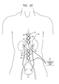
- FIG. 2C is a schematic illustration of the blood diverting device of FIG. 1C implanted in the aorta in the vicinity of the renal arteries, in accordance with some applications of the present invention
- FIG. 3A is a schematic illustration of a blood diverting device, in accordance with some applications of the present invention.
- FIG. 3B is a schematic illustration of a blood diverting device, in accordance with another application of the present invention.
- FIG. 4 is a schematic illustration of a blood diverting device implanted inside a vein, in accordance with some applications of the present invention
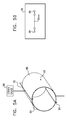
- FIGS. 5A-B are schematic illustrations of a set-up of an experiment that was conducted in accordance with an application of the present invention.
- FIGS. 6A-B are graphs showing the tension that was measured in an aortic ring before, during and after stimulation of the ring by, respectively, two ipsilaterally disposed electrodes ( FIG. 6A ), and two contralaterally disposed electrodes ( FIG. 6B );
- FIGS. 7A-C are graphs showing the tension that was measured in the aortic ring during stimulation of the ring with the ipsilaterally disposed electrodes using respective stimulation parameters.
- FIGS. 8A-D are graphs showing the tension measured in an aortic ring in response to electrical stimulation ( FIGS. 8A-B ), and in response to the administration of substance P neuropeptide ( FIGS. 8C-D ).
- FIG. 1A is a schematic illustration of a blood diverting device 10 , in accordance with some applications of the present invention.
- Blood diverting device 10 comprises an electrode 26 coupled to a wire frame 28 .
- a control unit 30 coupled to wire frame 28 , is configured to drive electrode 26 to apply an electric current to a local portion of the wall of a first blood vessel 22 , causing contraction of this portion of the wall of first blood vessel 22 .
- Contraction of the wall of first blood vessel 22 diverts blood away from first blood vessel 22 into a second blood vessel 24 of the subject, enhancing the perfusion of second blood vessel 24 .
- blood diverting device 10 is designated for implantation into first blood vessel 22 of the subject.
- blood diverting device 10 is typically implanted within first blood vessel 22 at a site that is downstream with respect to the bifurcation with second blood vessel 24 of the subject.
- the words “upstream” and “downstream” are to be understood as being with respect to the natural direction of blood flow.
- blood diverting device 10 is designated for implantation for a relatively short period, e.g., up to about one month (for example, two weeks).
- blood diverting device 10 is designated for chronic implantation, i.e., for a period of greater than one month.
- control unit 30 stimulates contraction of a portion of the wall of first blood vessel 22 by driving an electric current with an amplitude of more than 1 mA, and/or less than 20 mA (e.g., 1-20 mA) into a portion of the wall of first blood vessel 22 .
- the electric current has a frequency of more than 10 Hz, and/or less than 250 Hz (e.g., 10-250 Hz).
- the electric current is typically driven in a series of pulses, each having a duration of more than 0.5 and/or less than 10 ms (e.g., 0.5-10 ms).
- the control unit drives a current having an amplitude of 3 mA to 10 mA, a frequency of 6 Hz to 20 Hz, and a pulse duration of 0.3 ms to 2 ms.
- the current may be driven in a biphasic, monophasic, symmetric and/or asymmetric pulse.
- the control unit causes the blood vessel to contract by stimulating a nerve, by driving the current into the first blood vessel.
- the control unit drives the current into a third blood vessel that is located in a vicinity of the first blood vessel in order to cause the first blood vessel to contract.
- control unit 30 detects the subject's cardiac cycle and drives the current in coordination with the subject's cardiac cycle.
- the control unit drives the current irrespective of the phase of the subject's cardiac cycle.
- the scope of the present invention includes the control unit driving the current during an alternative phase of the cardiac cycle, or not in coordination with the cardiac cycle.
- a blood pressure sensor 29 is coupled to blood diverting device 10 , and is configured to detect the blood pressure of the subject at a particular location within the body of the subject, for example, at or adjacent to the bifurcation of first blood vessel 22 and second blood vessel 24 .
- Blood pressure sensor 29 measures the blood pressure of the subject and sends a signal to control unit 30 .
- control unit 30 adjusts the amplitude of the current in accordance with the sensed blood pressure of the subject.
- control unit 30 on receiving a sensed blood pressure with a value below 80 mmHg, may increase the amplitude of the current by more than 10% and/or less than 50%, e.g., 10-50%, and sense the pressure at the bifurcation again after having increased the current amplitude.
- control unit 30 may decrease the amplitude of the current by more than 10% and/or less than 50%, e.g., 10-50%.
- the threshold value of 80 mmHg may be varied depending on the anatomical location sensed and the state of the patient. For some applications, the threshold value is more than 80 mmHg and/or less than 120 mmHg, e.g., 80-120 mmHg.
- parameters of the subject are detected via an impedance sensor, a pressure sensor (e.g., for sensing wedge pressure), a breathing sensor, and/or a fluid sensor, and blood diverting device 10 operates in a closed-loop cycle, responsively to the parameters detected by the sensor.
- a pressure sensor e.g., for sensing wedge pressure
- a breathing sensor e.g., for sensing wedge pressure
- a fluid sensor e.g., blood diverting device 10 operates in a closed-loop cycle, responsively to the parameters detected by the sensor.
- one or more of the aforementioned sensors sense parameters of the subject's left ventricle and/or left atrium.
- electrodes 26 are disposed on (e.g., wrapped around) wire frame 28 .
- wire frame 28 is made of nitinol, and/or the electrodes are made of platinum iridium.
- sensing electrodes are disposed on the wire frame. The sensing electrodes are typically separated from the stimulation electrodes, in order to prevent the stimulation signal from interfering with the signal that is detected by the sensing electrodes.
- control unit 30 drives electrodes 26 wirelessly.
- an antenna may be disposed on wire frame 28 and the control unit drives the electrodes wirelessly via the antenna that is disposed on the wire frame.
- the wire frame may include a piezoelectric element that is driven by an ultrasound transducer that is outside the subject's body.
- the control unit is not implanted inside the subject's body but is worn, or otherwise disposed, outside the subject's body.
- the control unit in addition to the electrodes, is implanted inside the subject's body.
- control unit 30 transmits a signal for driving the electrodes via a transmitter (e.g., a transmitting coil) that is placed inside a vein of the subject.
- a transmitter e.g., a transmitting coil
- the control unit may be implanted inside the subject's body, and/or outside the subject's body, and wiredly coupled to the transmitter.
- the transmitter may be placed in the subject's pulmonary vein (or another vein) and a signal may be driven via the transmitter to an antenna disposed on wire frame 28 , the wire frame being disposed in the subject's aorta.
- the scope of the present invention includes driving with a control unit any stimulating or sensing electrodes that are disposed in an artery of a subject, via a transmitter (e.g., a transmitting coil) that is wiredly connected to the control unit and that is placed inside a vein that is in the vicinity of the artery.
- a transmitter e.g., a transmitting coil
- the electrodes may be placed in the aorta, a carotid artery, a subclavian artery, and/or the pulmonary artery
- the transmitter may be placed in the pulmonary vein, innominate vein, vena cava, jugular vein, and/or subclavian vein.
- the transmitter is placed inside the vein such that it is at a distance from the intra-arterial electrodes of more than 5 mm and/or less than 20 mm, e.g., 5-20 mm.
- placement of the transmitter in the vein facilitates transmission of the signal from the control unit to the electrodes, due to the proximity of the vein to the artery in which the electrodes are placed.
- the dimensions of the vein are such that the vein is able to accommodate a transmitting coil, even in the absence of a rigid housing for housing the coil.
- FIG. 1B is a schematic illustration of a blood diverting device 20 , in accordance with some applications of the present invention.
- Blood diverting device 20 is generally similar to blood diverting device 10 as described hereinabove with reference to FIG. 1A , except for differences as described hereinbelow.
- Blood diverting device 20 comprises a plurality of electrodes 26 coupled to wire frame 28 .
- control unit 30 drives a current into the plurality of electrodes 26 .
- the current is configured to cause contraction of the wall of first blood vessel 22 .
- control unit may drive each one of electrodes 26 in sequence, from the most downstream electrode 26 toward the most upstream electrode 26 , in order to generate a wave of peristaltic contraction in the wall of first blood vessel 22 , thereby diverting blood into second blood vessel 24 of the subject.
- first and second electrodes 26 are placed within blood vessel 22 at a longitudinal distance from each other of between 10 mm and 30 mm and/or at a radial distance from each other of less than 10 degrees.
- the first and second electrodes 26 are placed within blood vessel 22 at a longitudinal distance from each other of between 2 mm and 10 mm.
- ten or more electrodes are implanted inside blood vessel 22 .
- the electrodes are oriented to have a surface area of between 3 mm2 and 15 mm2, e.g. between 5 mm2 and 12 mm2, in contact with tissue of blood vessel 22 .
- the electrodes are configured to induce contraction of blood vessel 22 by a current being driven via respective electrodes with a spacing in time of 10 ms to 50 ms.
- the electrodes are disposed longitudinally along the blood vessel with a longitudinal spacing therebetween of 150%-250% of the local diameter of the blood vessel, and/or of 1-5 cm.
- the spacing may be maintained, for example, by wire frame 28 (as shown), by a housing to which the electrodes are coupled (e.g., a flexible stent), or by sutures or adhesives which couple the electrodes to the aorta.
- the time for a peristaltic wave to be generated and to travel from the most downstream of the most upstream electrode (or in the opposite direction) typically ranges from 0.25 second to about 2 seconds.
- a current having the same parameters is driven via each of the electrodes.
- a current having a first set of parameters is driven via a first one of electrodes 26
- a current having a second set of parameters is driven via a second one of the electrodes.
- wire frame 28 is highly flexible and/or has a different configuration from the figure-of-eight configuration shown in the figures.
- electrodes 26 are not disposed on a wire frame.
- the electrodes may be implanted on the inside and/or the outside of blood vessel 22 , and/or within the wall of the blood vessel.
- the electrodes are not placed in direct contact with the blood vessel, but are implanted in the vicinity of the blood vessel, and/or in contact with, or in the vicinity of, a nerve that innervates the blood vessel.
- the electrodes may be driven to stimulate parasympathetic nerve endings in order to induce relaxation of the blood vessel, and/or sympathetic nerve endings in order to induce contraction of the blood vessel.
- monopolar electrodes are used to drive a current into the blood vessel.
- FIG. 1C is a schematic illustration of a blood diverting device 40 , in accordance with some applications of the present invention.
- Blood diverting device 40 is generally similar to blood diverting device 10 and blood diverting device 20 , as described hereinabove with reference to FIG. 1A and FIG. 1B , except for differences as described hereinbelow.
- Blood diverting device 40 comprises a first and a second set of one or more electrodes 26 , coupled to a first wire frame 28 and a second wire frame 28 respectively.
- the first wire frame 28 is implanted into first blood vessel 22 at a site downstream of the bifurcation with second blood vessel 24
- the second wire frame 28 is implanted into first blood vessel 22 at a site upstream of the bifurcation with second blood vessel 24 .
- each of the wire frames 28 comprises a single electrode.
- a single wire frame acts as a support element for the first and the second sets of the electrodes.
- the first and second sets of electrodes are disposed respectively on downstream (e.g., proximal) and upstream (e.g., distal) portions of the wire frame.
- Control unit 30 is configured to drive a first current via the first set of electrodes 26 and a second current via the second set of electrodes 26 .
- the first current and the second current are configured to cause contraction of the wall of first blood vessel 22 .
- control unit 30 may drive the first current sequentially into each one of electrodes 26 coupled to the first wire frame, from the most downstream electrode 26 toward the most upstream electrode 26 , in order to generate a wave of peristaltic contraction in the wall of first blood vessel 22 downstream of the bifurcation with second blood vessel 24 .
- control unit 30 may drive the second current sequentially into each one of electrodes 26 coupled to the second wire frame, from the most upstream electrode 26 toward the most downstream electrode 26 , in order to generate a wave of peristaltic contraction in the wall of first blood vessel 22 upstream of the bifurcation with second blood vessel 24 .
- These two waves of contraction generated at generally the same time on either side of the bifurcation with second blood vessel 24 , towards the bifurcation with second blood vessel 24 increase the pressure of the blood between first and second wire frames 28 , thereby diverting blood into second blood vessel 24 .
- control unit 30 is configured to drive the first current and the second current into the first and the second set of electrodes 26 at substantially the same time.
- control unit applies the first and second currents at slightly different times, but typically within one heartbeat of each other.
- FIG. 2A is a schematic illustration of blood diverting device 20 as described hereinabove with reference to FIG. 1B , implanted in aorta 23 of the subject in the vicinity of a coronary artery 25 of the subject, in accordance with some applications of the present invention.
- Blood diverting device 20 is designated for implantation within aorta 23 at a site downstream of the bifurcation with the right and left coronary arteries 25 .
- Control unit 30 drives a current into electrodes 26 during diastole configured to cause contraction of the wall of aorta 23 downstream of the bifurcation with the right and the left coronary arteries 25 .
- the control unit may drive each one of electrodes 26 in sequence, from the most downstream electrode 26 toward the most upstream electrode 26 , in order to generate a wave of peristaltic contraction in the wall of aorta 23 , thereby diverting blood into coronary arteries 25 of the subject.
- device 20 does not generate a wave of peristaltic contraction, but instead generally simultaneously constricts the portion of aorta 23 affected by the current, whereby some blood flows from the aorta into coronary arteries 25 .
- FIG. 2B is a schematic illustration of blood diverting device 20 as described hereinabove with reference to FIG. 1B , implanted in aorta 23 of the subject in the vicinity of right and left carotid artery 21 of the subject, in accordance with some applications of the present invention.
- Blood diverting device 20 is designated for implantation into aorta 23 of the subject at a site downstream of the bifurcation with left carotid artery 21 .
- Control unit 30 drives a current into electrodes 26 during systole, configured to generate contraction of the wall of aorta 23 downstream of the bifurcation with left carotid artery 21 , using techniques described hereinabove with respect to FIG. 1B .
- control unit 30 may drive each one of electrodes 26 in sequence, from the most downstream electrode 26 toward the most upstream electrode 26 , in order to generate a wave of peristaltic contraction in the wall of aorta 23 , thereby diverting blood into carotid arteries 21 of the subject.
- control unit 30 drives a current that does not induce a peristaltic wave of contraction, but instead generates a single contraction, typically during systole, in order to increase blood pressure upstream of wire frame 28 , and thereby enhance blood flow to carotid arteries 21 .
- wire frame 28 is typically placed near the top of the aortic arch, between the left and right carotid arteries.
- a second wire frame 28 (or a second set of electrodes 26 , which are not disposed on a wire frame) is designated for implantation within aorta at a site upstream of the bifurcation with right carotid artery 21 , as described hereinabove with respect to FIG. 1C .
- Control unit 30 drives a current into the plurality of electrodes 26 configured to cause contraction of the wall of aorta 23 upstream of the bifurcation with right carotid artery 21 of the subject, thereby diverting blood into carotid arteries 21 of the subject using techniques described hereinabove with respect to FIG. 1C .
- control unit may drive each one of electrodes 26 in sequence, from the most upstream electrode 26 toward the most downstream electrode 26 , in order to generate a wave of peristaltic contraction in the wall of aorta 23 .
- the waves of contraction generated by the two wire frames increase blood pressure at the top of the aortic arch, thereby diverting blood into the right and left carotid arteries 21 of the subject.
- the two peristaltic waves are typically generated during diastole.
- FIG. 2C is a schematic illustration of blood diverting device 40 as described hereinabove with reference to FIG. 1C , implanted within aorta 23 of the subject in the vicinity of a renal artery 74 of the subject, in accordance with some applications of the present invention.
- placement of device 40 in the vicinity of renal artery 74 is shown by way of illustration and not limitation, and the scope of the present invention includes placement of device 40 at any site downstream of the right carotid artery 21 (e.g., between the right and left carotid arteries, slightly downstream of the left carotid artery 21 , or in the vicinity of another artery, such as renal artery 74 ).
- Blood diverting device 40 comprises a first and a second set of one or more electrodes 26 , which are typically coupled to a first wire frame 28 and a second wire frame 28 respectively.
- first wire frame 28 or a set of electrodes 26 , which are not disposed on a wire frame
- second wire frame 28 or a second set of electrodes 26 , which are not disposed on a wire frame
- Control unit 30 is configured to drive a first current via the first set of electrodes 26 and a second current via the second set of electrodes 26 .
- the first and the second current are configured to cause contraction of the wall of aorta 23 upstream of the bifurcation and downstream of the bifurcation with renal arteries 74 , increasing blood pressure at the bifurcation, and thereby diverting blood into renal arteries 74 of the subject.
- control unit 30 drives a current into the plurality of electrodes 26 during systole or during diastole to generate contraction of the wall of aorta 23 downstream of the bifurcation with renal arteries 74 .
- control unit 30 may drive each one of electrodes 26 in sequence, from the most downstream electrode 26 toward the most upstream electrode 26 , in order to generate a wave of peristaltic contraction in the wall of aorta 23 , thereby diverting blood into renal arteries 74 of the subject.
- control unit 30 drives a current that does not induce a peristaltic wave of contraction, but instead generates a single contraction at the wire frame 28 that is downstream of the bifurcation, typically during systole, in order to increase blood pressure upstream of wire frame 28 , and thereby enhance blood flow to renal arteries 74 .
- FIG. 3A is a schematic illustration of a blood diverting device 50 , in accordance with some applications of the present invention.
- Blood diverting device 50 is generally similar to blood diverting device 20 , as described hereinabove with reference to FIG. 1A , except for differences as described hereinbelow.
- Blood diverting device 50 comprises one or more electrodes 26 coupled to a support element, e.g., catheter 52 .
- Catheter 52 is advanced within first blood vessel 22 of the subject.
- catheter 52 has a diameter of less than 35 mm.
- control unit 30 drives a current into electrodes 26 that is configured to cause contraction of the wall of first blood vessel 22 .
- control unit 30 may drive each one of electrodes 26 in sequence, from the most downstream electrode toward the most upstream electrode 26 , in order to generate a wave of peristaltic contraction in the wall of first blood vessel 22 , thereby increasing blood pressure at the bifurcation and diverting blood into second blood vessel 24 .
- first blood vessel 22 includes an aorta of the subject.
- second blood vessel 24 includes a carotid artery of the subject.
- second blood vessel 24 includes a renal artery of the subject.
- second blood vessel 24 includes a coronary artery of the subject.
- control unit 30 drives a current that does not induce a peristaltic wave of contraction, but instead generates a single contraction of first blood vessel 22 downstream of the bifurcation, typically during systole, in order to increase blood pressure at the bifurcation, and thereby enhance blood flow to second blood vessel 24 .
- FIG. 3B is a schematic illustration of a blood diverting device 60 , in accordance with some applications of the present invention.
- Blood diverting device 60 is generally similar to blood diverting device 40 , as described hereinabove with reference to FIG. 1C , except for differences as described hereinbelow.
- Blood diverting device 60 comprises a first and a second set of one or more electrodes 26 coupled to proximal and distal portions of a support element, e.g., catheter 52 .
- catheter 52 is advanced into first blood vessel 22 such that the proximal portion of the catheter and the first set of electrodes 26 are positioned downstream of the bifurcation with second blood vessel 24 (i.e., further from the heart, to the lower right in the figure), and the distal portion of the catheter and the second set of electrodes 26 are positioned upstream of the bifurcation with second blood vessel 24 , as shown.
- Control unit 30 is configured to drive a first current via the first set electrodes 26 and a second current via the second set of electrodes 26 .
- the first current and the second current are configured to cause contraction of the wall of first blood vessel 22 , downstream of the bifurcation with second blood vessel 24 and upstream of the bifurcation with second blood vessel 24 , respectively.
- control unit 30 may drive the first current sequentially into each one of electrodes 26 in the first set of electrodes 26 , from the most downstream electrode 26 toward the most upstream electrode 26 , in order to generate a wave of peristaltic contraction in the wall of first blood vessel 22 downstream of the bifurcation with second blood vessel 24 .
- Control unit 30 may also drive the second current sequentially into each one of electrodes 26 in the second set of electrodes 26 , from the most upstream electrode 26 to the most downstream electrode 26 , in order to generate a wave of peristaltic contraction in the wall of first blood vessel 22 upstream of the bifurcation with second blood vessel 24 .
- These two waves of contraction generated on either side of the bifurcation with second blood vessel 24 increase pressure at the bifurcation, and thereby divert blood into second blood vessel 24 .
- electrodes belonging to each of the sets of electrodes 26 are disposed longitudinally along catheter 52 with a longitudinal spacing d from an adjacent electrode of the set of electrodes of more than 10 mm and/or less than 30 mm, e.g., 10-30 mm.
- electrodes belonging to each of the sets of the electrodes 26 are disposed longitudinally along catheter 52 with a longitudinal spacing d from an adjacent electrode of the set of electrodes of more than 2 mm and/or less than 10 mm, e.g., 2-10 mm.
- a distal-most electrode in the first set of electrodes and a proximal-most electrode in the second set of electrodes are disposed at a longitudinal distance D from one another of more than 1 cm and/or less than 5 cm, e.g., 1-5 cm.
- the distal-most electrode in the first set of electrodes and the proximal-most electrode in the second set of electrodes are disposed at a longitudinal distance D from one another of more than 10 cm and/or less than 30 cm, e.g., 10-30 cm.
- FIG. 4 is a schematic illustration of blood diverting device 10 inside blood vessel 22 , the blood vessel being a vein, in accordance with some applications of the present invention.
- device 10 is shown in FIG. 4 , the scope of the present invention includes using, to apply a current to vein 22 , any of devices 20 , 40 , 50 , or 60 , and/or any other apparatus and techniques described herein.
- vein 22 is a jugular vein, subclavian vein, pulmonary vein, and/or the vena cava.
- Device 10 causes vein 22 to contract (typically, peristaltically), using the techniques described herein.
- the contraction of blood vessel 22 causes the blood flow in the downstream direction, i.e., into blood vessel 24 , be enhanced.
- this lowers the pressure inside vein 22 which causes more blood to flow from the organ into blood vessel 22 , in the direction of arrow 70 .
- this technique is used to enhance venous return from the legs.
- the scope of the present invention includes using any of the devices or techniques described hereinabove, to increase the blood flow from first vein 22 to second vein 24 .
- wire frame 28 is configured to prevent the vein from collapsing during the constriction of the vein, and/or to restore the shape of first vein 22 after the vein has been contracted.
- wire frame 28 may be made of a shape-memory alloy, such as nitinol, that is configured to assume an expanded shape, when not being constrained by the contraction of vein 22 .
- the expansion of the shape-memory alloy causes the vein to expand and assume its original shape, and facilitates refilling of the vein and perfusion of the organ upstream of the site of wire frame 28 .
- wire frame 28 may be made of an elastic material that is configured to assume an expanded shape, when not being constrained by the contraction of vein 22 .
- FIGS. 5A-B are schematic illustrations of apparatus that was used in an experiment that was conducted in accordance with an application of the present invention.
- a 15 mm ring 80 of an aorta was dissected from a pig, and was held in place using upper and lower support elements 82 and 84 .
- Upper support element 82 was connected to a strain gauge 86 , such that the strain gauge measured the tension in the aortic ring.
- Two unipolar epicardial electrodes (Medtronic CapSure Epi 4965) were placed on the adventitia of the aortic ring on one side of the aortic ring (i.e., ipsilaterally to each other, with respect to the aortic ring).
- the ipsilateral electrodes were coupled to one another by a custom made support 89 (shown in FIG. 5B ), at a longitudinal distance of 10 mm from one another.
- Another electrode 90 was placed on the adventitia of the aortic ring on the side of the aortic ring contralateral to the side on which electrodes 88 were placed.
- Aortic ring 80 was electrically stimulated during respective time periods by (a) driving a current into the aortic ring via the two ipsilateral electrodes 88 , and (b) driving a current into the aortic ring via one of electrodes 88 and contralateral electrode 90 .
- the current was driven at an amplitude of 15 mA, with a frequency of 50 Hz, and with a pulse width of 4 ms.
- the tension in the aortic ring before, during, and after stimulation of the aortic ring by the electrodes was measured.
- FIGS. 6A-B are graphs showing the tension that was measured in aortic ring 80 before, during and after stimulation of the ring by, respectively, the two ipsilateral electrodes ( FIG. 6A ), and contralateral electrodes ( FIG. 6B ).
- the beginning and end of the stimulation periods are denoted by the vertical dashed lines in the graphs.
- stimulation of the aortic ring with the ipsilateral electrodes resulted in a decrease in the tension of the aortic ring.
- the aortic ring recovered its pre-stimulation level of tension about 150 seconds after the stimulation period finished.
- Stimulation of the aortic via contralateral electrodes resulted in an increase in the tension of the ring.
- an artery is constricted by driving a current into the artery via electrodes that are disposed contralaterally to each other, with respect to the artery.
- an artery is dilated by driving a current into the artery via electrodes that are disposed ipsilaterally to each other, with respect to the artery.
- current is driven into the artery via electrodes that are disposed ipsilaterally to each other, with respect to the artery.
- FIGS. 7A-C are graphs showing the tension that was measured in aortic ring 80 during stimulation of the ring with ipsilateral electrodes 88 , using respective stimulation parameters.
- FIG. 7A is a graph showing the change in the tension measured in aortic ring 80 relative to the pre-stimulation tension in the ring, during stimulation of the ring with a current having a pulse width of 4 ms, and a frequency of 50 Hz, over a range of amplitudes. It may be observed that the greatest decrease in the tension in the ring was for currents having amplitudes of more than 15 mA, and/or less than 35 mA (e.g., 15 mA-35 mA), for example, more than 25 mA, and/or less than 33 mA (e.g., 25 mA-33 mA).
- FIG. 7B is a graph showing the change in the tension measured in aortic ring 80 relative to the pre-stimulation tension in the ring, during stimulation of the ring with a current having an amplitude of 15 mA, and a frequency of 50 Hz, for a range of pulse widths. It may be observed that the greatest decrease in the tension in the ring was for currents having pulse widths of more than 1 ms, and/or less than 5 ms (e.g., 1 ms-5 ms), for example, more than 2 ms, and/or less than 4 ms (e.g., 2 ms-4 ms).
- FIG. 7C is a graph showing the change in the tension measured in aortic ring 80 relative to the pre-stimulation tension in the ring, during stimulation of the ring with a current having a pulse width of 4 ms, and an amplitude of 15 mA, for a range of frequencies. It may be observed that the greatest decrease in the tension in the ring was for currents having a frequency of more than 20 Hz (e.g., more than 50 Hz), for example, 20 Hz-100 Hz.
- a subject is identified as suffering from a condition, which may be at least partially treated by causing blood vessels of the subject to dilate (e.g., by causing an artery of the subject to peristaltically dilate, as described in US 2009/0198308 to Gross and US 2009/0198097 to Gross, both of which applications are incorporated herein by reference).
- electrodes are placed in contact with the subject's blood vessel such that the electrodes are disposed ipsilaterally to each other, with respect to the blood vessel, in accordance with the results shown in FIG. 6A .
- the electrodes may be disposed on the same side of the inner surface of a ring that is placed around the blood vessel.
- the electrodes may be disposed on wire frame 28 ( FIG. 1A ), or on catheter 52 ( FIG. 3B ), such that the electrodes are placed in contact with the blood vessel ipsilaterally to each other, with respect to the blood vessel.
- a current having one or more of the following parameters is driven via the electrodes, in order to cause dilation of a blood vessel of the subject, in accordance with the results shown in FIGS. 7A-C :
- a subject is identified as suffering from a condition, which may be at least partially treated by causing blood vessels of the subject to constrict.
- electrodes are placed on the subject's blood vessel such that the electrodes are disposed contralaterally to each other, with respect to the blood vessel, in accordance with the results shown in FIG. 6B .
- the electrodes may be disposed on opposite sides of the inner surface of a ring that is placed around the blood vessel.
- the electrodes may be disposed on wire frame 28 ( FIG. 1A ), or on catheter 52 ( FIG. 3B ) such that the electrodes are placed in contact with the blood vessel, contralaterally with respect to one another.
- FIGS. 8A-D are graphs showing the tension measured in aortic ring 80 in response to electrical stimulation ( FIGS. 8A-B ), and in response to the administration of substance P neuropeptide ( FIGS. 8C-D ).
- FIG. 8A is a graph showing the tension measured in an aortic ring measured before, during, and after stimulation of the ring with ipsilateral electrodes using a current having an amplitude of 15 mA, a frequency of 50 Hz, and a pulse width of 4 ms.
- the beginning and end of the stimulation period is denoted by the vertical dashed lines on FIG. 8A .
- FIG. 8B shows the tension measured in an aortic ring before, during, and after stimulation of the ring with ipsilateral electrodes using a current having an amplitude of 15 mA, a frequency of 50 Hz, and a pulse width of 4 ms.
- FIG. 8C is a graph showing the tension measured in an aortic ring measured before, and after administration of substance P neuropeptide to the aortic ring.
- the time at which the substance P was administered is denoted by the downward-pointing arrow in FIG. 8C .
- FIG. 8D is a graph showing the tension measured in an aortic ring measured before, and after administration of substance P neuropeptide to the aortic ring.
- the time at which the substance P was administered is denoted by the downward-pointing arrow in FIG. 8D .
- the endothelial wall of the aortic ring was mechanically denuded.
- Substance P is a vasodilator.
- Substance-P-induced vasodilation has been shown to be dependent on the release of nitric oxide from the endothelium (c.f. “In vivo measurement of endothelium-dependent vasodilation with substance P in man,” Bossaller, Herz. 1992 October; 17(5):284-90). This explains the data shown in FIGS. 8C-D , namely, that substance P was effective at reducing tension in the aortic ring before the endothelial denuding, but not subsequent to the endothelial denuding.
- the data shown in FIGS. 8A-B indicate that the mechanism by which electrical stimulation of the aortic ring causes the aortic ring to dilate is at least partially due to the release of endothelium-derived nitric oxide NO. Thus, subsequent to endothelial denuding, electrical stimulation is not effective to dilate the aortic ring.
- peristaltic waves both upstream and downstream of a bifurcation
- other embodiments of the present invention include generating a peristaltic wave on one side of the bifurcation, and generating a non-peristaltic contraction on the other side of the bifurcation, in order to increase blood pressure at the bifurcation and divert blood to the adjacent blood vessel and/or enhance blood flow through the blood vessel undergoing the contraction.
- two non-peristaltic contractions may be created, on either side of the bifurcation, in order to increase blood pressure at the bifurcation and divert blood to the adjacent blood vessel.
- the scope of the present invention includes applying the method and apparatus described herein to any arteries or veins within a subject's body, e.g., the first or the second blood vessel may be the femoral artery, or the femoral vein.
- embodiments of the present invention which include inducing contraction of a blood vessel do not necessarily completely occlude the blood vessel, but may only cause a decrease in diameter of the blood vessel.
- transient occlusion of the blood vessel may be induced, typically in intermittent cardiac cycles or in every cardiac cycle for an appropriate time period.
Abstract
Description
- U.S. Pat. No. 4,809,676 to Freeman
- U.S. Pat. No. 5,324,323 to Bui
- U.S. Pat. No. 5,372,573 to Habib
- U.S. Pat. No. 5,612,314 to Stamler
- U.S. Pat. No. 5,669,924 to Shaknovich
- U.S. Pat. No. 5,782,774 to Shmulewitz
- U.S. Pat. No. 5,900,433 to Igo
- U.S. Pat. No. 5,904,712 to Axelgaard
- U.S. Pat. No. 5,906,641 to Thompson
- U.S. Pat. No. 5,913,876 to Taylor
- U.S. Pat. No. 5,935,077 to Ogle
- U.S. Pat. No. 6,038,485 to Axelgaard
- U.S. Pat. No. 6,058,331 to King
- U.S. Pat. No. 6,086,527 to Talpade
- U.S. Pat. No. 6,106,477 to Miesel
- U.S. Pat. No. 6,200,259 to March
- U.S. Pat. No. 6,245,103 to Stinson
- U.S. Pat. No. 6,280,377 to Talpade
- U.S. Pat. No. 6,347,247 to Dev
- U.S. Pat. No. 6,463,323 to Conrad-Vlasak
- U.S. Pat. No. 6,485,524 to Strecker
- U.S. Pat. No. 6,721,603 to Zabara
- U.S. Pat. No. 6,810,286 to Donovan
- U.S. Pat. No. 6,824,561 to Soykan
- U.S. Pat. No. 6,845,267 to Harrison
- U.S. Pat. No. 6,865,416 to Dev
- U.S. Pat. No. 6,871,092 to Piccone
- U.S. Pat. No. 6,939,345 to KenKnight
- U.S. Pat. No. 7,082,336 to Ransbury
- U.S. Pat. No. 7,090,648 to Sackner
- U.S. Pat. No. 7,167,751 to Whitehurst
- U.S. Pat. No. 7,206,637 to Salo
- U.S. Pat. No. 7,229,403 to Schock
- U.S. Pat. No. 7,269,457 to Shafer
- US 2002/0169413 to Keren
- US 2002/0103454 to Sackner
- US 2003/0036773 to Whitehurst
- US 2003/0204206 to Padua
- US 2004/0039417 to Soykan
- US 2004/0064090 to Keren
- US 2004/0106954 to Whitehurst
- US 2005/0154418 to Kieval
- US 2006/0229677 to Moffit
- US 2006/0217772 to Libbus
- US 2006/0276844 to Alon
- US 2007/0196428 to Glauser
- US 2007/015009 to Kveen
- US 2007/0248676 to Stamler
- US 2008/0058872 to Brockway
- US 2009/0062874 to Tracey
- US 2010/0010556 to Zhao
- PCT Publication WO 00/002501 to Benjamin
- PCT Publication WO 04/014456 to Allen
- PCT Publication WO 06/094273 to White
- PCT Publication WO 06/064503 to Belsky
- PCT Publication WO 06/123346 to Alon
- PCT Publication WO 07/064895 to Meyerhoff
- PCT Publication WO 07/106533 to Stern
- PCT Publication WO 07/113833 to Cahan
- PCT Publication WO 07/113818 to Cahan
- PCT Publication WO 08/100390 to Walker
- PCT Publication WO 09/095918 to Gross
- PCT Publication WO 09/095920 to Gross
- European Patent
Application Publication EP 0 109 935 A1 to Charmillot - “Vagus nerve stimulation as a method to temporarily slow or arrest the heart,” by Matheny, Ann Thorac Surg. 1997 June; 63(6 Suppl): S28-9
- “Vagus nerve stimulation decreases left ventricular contractility in vivo in the human and pig heart,” by Lewis, J. Physiol. 2001 Jul. 15; 534(Pt 2): 547-552
- “Sympathovagal balance is major determinant of short-term blood pressure variability in healthy subjects,” by Laitinen, Am J Physiol Heart Circ Physiol 276:1245-1252, 1999
- “Preparation and characterization of implantable sensors with nitric oxide release coatings,” by M C Frost, Microchemical Journal Vol: 74 Issue: 3, June, 2003 pp: 277-288
- “Optimal frequency ranges for extracting information on cardiovascular autonomic control from the blood pressure and pulse interval spectrograms in mice,” by Baudrie, Am J Physiol Regul Integr Comp Physiol 292: R904-R912, 2007
- “Neural influences on cardiovascular variability: possibilities and pitfalls,” by Malpas, Am J Physiol Heart Circ Physiol 282: H6-H20, 2002
- “Improving the thromboresistivity of chemical sensors via nitric oxide release: fabrication and in vivo evaluation of NO-releasing oxygen-sensing catheters,” by M H Schoenfisch, Anal. Chem., 72 (6), 1119-1126, 2000
- “Improving the biocompatibility of in vivo sensors via nitric oxide release,” by Jae Ho Shin, Analyst, 2006, 131, 609-615
- “Heart rate variability,” by Task Force of the European Society of Cardiology and the North American Society of Pacing and Electrophysiology, European Heart Journal (1996) 17, 354-381
- “Heart rate and vasomotor control during exercise,” by Vallais, Proceedings of the 29th Annual International Conference of the IEEE EMBS, Cité Internationale, Lyon, France, Aug. 23-26, 2007
- “Endogenous and exogenous nitric oxide protect against intracoronary thrombosis and reocclusion after thrombolysis,” by Sheng-Kun Yao, Circulation. 1995; 92:1005-1010
- “Effects of chronic baroreceptor stimulation on the autonomic cardiovascular regulation in patients with drug-resistant arterial hypertension,” by Wustmann, Hypertension 2009; 54; 530-536
-
- generating a peristaltic wave of constriction in an upstream direction, along the wall of the first artery, by driving the first set of electrodes to apply a first current to the wall of the first artery, and
- generating a peristaltic wave of constriction in a downstream direction, along the wall of the first artery, by driving the second set of electrodes to apply a second current to the wall of the first artery.
-
- an amplitude of more than 15 mA, and/or less than 35 mA (e.g., 15 mA-35 mA), for example, more than 25 mA, and/or less than 33 mA (e.g., 25 mA-33 mA);
- a pulse width of more than 1 ms, and/or less than 5 ms (e.g., 1 ms-5 ms), for example, more than 2 ms, and/or less than 4 ms (e.g., 2 ms-4 ms); and/or
- a frequency of more than 20 Hz (e.g., more than 50 Hz), for example, 20 Hz-100 Hz.
- US 2008/0215117 to Gross
- US 2009/0198097 to Gross
- US 2009/0198308 to Gross
Claims (9)
Priority Applications (8)
| Application Number | Priority Date | Filing Date | Title |
|---|---|---|---|
| US12/851,214 US8538535B2 (en) | 2010-08-05 | 2010-08-05 | Enhancing perfusion by contraction |
| US12/957,799 US8626299B2 (en) | 2008-01-31 | 2010-12-01 | Thoracic aorta and vagus nerve stimulation |
| EP11814203.3A EP2600935A4 (en) | 2010-08-05 | 2011-08-04 | Enhancing perfusion by contraction |
| PCT/IL2011/000636 WO2012017437A1 (en) | 2010-08-05 | 2011-08-04 | Enhancing perfusion by contraction |
| US13/210,778 US8626290B2 (en) | 2008-01-31 | 2011-08-16 | Acute myocardial infarction treatment by electrical stimulation of the thoracic aorta |
| US13/968,868 US9649487B2 (en) | 2010-08-05 | 2013-08-16 | Enhancing perfusion by contraction |
| US14/144,024 US20140114377A1 (en) | 2008-01-31 | 2013-12-30 | Vagus nerve stimulation |
| US14/617,088 US20150151121A1 (en) | 2008-01-31 | 2015-02-09 | Enhancing perfusion by contraction |
Applications Claiming Priority (1)
| Application Number | Priority Date | Filing Date | Title |
|---|---|---|---|
| US12/851,214 US8538535B2 (en) | 2010-08-05 | 2010-08-05 | Enhancing perfusion by contraction |
Related Child Applications (3)
| Application Number | Title | Priority Date | Filing Date |
|---|---|---|---|
| US12/023,896 Continuation-In-Part US9005106B2 (en) | 2008-01-31 | 2008-01-31 | Intra-aortic electrical counterpulsation |
| US12/957,799 Continuation-In-Part US8626299B2 (en) | 2008-01-31 | 2010-12-01 | Thoracic aorta and vagus nerve stimulation |
| US13/968,868 Continuation US9649487B2 (en) | 2008-01-31 | 2013-08-16 | Enhancing perfusion by contraction |
Publications (2)
| Publication Number | Publication Date |
|---|---|
| US20120035711A1 US20120035711A1 (en) | 2012-02-09 |
| US8538535B2 true US8538535B2 (en) | 2013-09-17 |
Family
ID=45556706
Family Applications (2)
| Application Number | Title | Priority Date | Filing Date |
|---|---|---|---|
| US12/851,214 Expired - Fee Related US8538535B2 (en) | 2008-01-31 | 2010-08-05 | Enhancing perfusion by contraction |
| US13/968,868 Active US9649487B2 (en) | 2008-01-31 | 2013-08-16 | Enhancing perfusion by contraction |
Family Applications After (1)
| Application Number | Title | Priority Date | Filing Date |
|---|---|---|---|
| US13/968,868 Active US9649487B2 (en) | 2008-01-31 | 2013-08-16 | Enhancing perfusion by contraction |
Country Status (3)
| Country | Link |
|---|---|
| US (2) | US8538535B2 (en) |
| EP (1) | EP2600935A4 (en) |
| WO (1) | WO2012017437A1 (en) |
Cited By (31)
| Publication number | Priority date | Publication date | Assignee | Title |
|---|---|---|---|---|
| US8855783B2 (en) | 2011-09-09 | 2014-10-07 | Enopace Biomedical Ltd. | Detector-based arterial stimulation |
| US8862243B2 (en) | 2005-07-25 | 2014-10-14 | Rainbow Medical Ltd. | Electrical stimulation of blood vessels |
| US9005106B2 (en) | 2008-01-31 | 2015-04-14 | Enopace Biomedical Ltd | Intra-aortic electrical counterpulsation |
| US20150151121A1 (en) * | 2008-01-31 | 2015-06-04 | Enopace Biomedical Ltd. | Enhancing perfusion by contraction |
| US9386991B2 (en) | 2012-02-02 | 2016-07-12 | Rainbow Medical Ltd. | Pressure-enhanced blood flow treatment |
| US9480790B2 (en) | 2005-09-12 | 2016-11-01 | The Cleveland Clinic Foundation | Methods and systems for treating acute heart failure by neuromodulation |
| US9486623B2 (en) | 2014-03-05 | 2016-11-08 | Rainbow Medical Ltd. | Electrical stimulation of a pancreas |
| US9526637B2 (en) | 2011-09-09 | 2016-12-27 | Enopace Biomedical Ltd. | Wireless endovascular stent-based electrodes |
| US9597205B2 (en) | 2012-06-06 | 2017-03-21 | Magenta Medical Ltd. | Prosthetic renal valve |
| US9649487B2 (en) | 2010-08-05 | 2017-05-16 | Enopace Biomedical Ltd. | Enhancing perfusion by contraction |
| US9764113B2 (en) | 2013-12-11 | 2017-09-19 | Magenta Medical Ltd | Curved catheter |
| US9913937B2 (en) | 2013-03-13 | 2018-03-13 | Magenta Medical Ltd. | Renal pump |
| US10172549B2 (en) | 2016-03-09 | 2019-01-08 | CARDIONOMIC, Inc. | Methods of facilitating positioning of electrodes |
| US10493278B2 (en) | 2015-01-05 | 2019-12-03 | CARDIONOMIC, Inc. | Cardiac modulation facilitation methods and systems |
| US10576273B2 (en) | 2014-05-22 | 2020-03-03 | CARDIONOMIC, Inc. | Catheter and catheter system for electrical neuromodulation |
| US10583231B2 (en) | 2013-03-13 | 2020-03-10 | Magenta Medical Ltd. | Blood pump |
| US10722716B2 (en) | 2014-09-08 | 2020-07-28 | Cardionomia Inc. | Methods for electrical neuromodulation of the heart |
| US10779965B2 (en) | 2013-11-06 | 2020-09-22 | Enopace Biomedical Ltd. | Posts with compliant junctions |
| US10881770B2 (en) | 2018-01-10 | 2021-01-05 | Magenta Medical Ltd. | Impeller for blood pump |
| US10894160B2 (en) | 2014-09-08 | 2021-01-19 | CARDIONOMIC, Inc. | Catheter and electrode systems for electrical neuromodulation |
| US10893927B2 (en) | 2018-03-29 | 2021-01-19 | Magenta Medical Ltd. | Inferior vena cava blood-flow implant |
| US11033727B2 (en) | 2016-11-23 | 2021-06-15 | Magenta Medical Ltd. | Blood pumps |
| US11039915B2 (en) | 2016-09-29 | 2021-06-22 | Magenta Medical Ltd. | Blood vessel tube |
| US11077298B2 (en) | 2018-08-13 | 2021-08-03 | CARDIONOMIC, Inc. | Partially woven expandable members |
| US11191944B2 (en) | 2019-01-24 | 2021-12-07 | Magenta Medical Ltd. | Distal tip element for a ventricular assist device |
| US11260212B2 (en) | 2016-10-25 | 2022-03-01 | Magenta Medical Ltd. | Ventricular assist device |
| US11291824B2 (en) | 2015-05-18 | 2022-04-05 | Magenta Medical Ltd. | Blood pump |
| US11291826B2 (en) | 2018-01-10 | 2022-04-05 | Magenta Medical Ltd. | Axially-elongatable frame and impeller |
| US11400299B1 (en) | 2021-09-14 | 2022-08-02 | Rainbow Medical Ltd. | Flexible antenna for stimulator |
| US11559687B2 (en) | 2017-09-13 | 2023-01-24 | CARDIONOMIC, Inc. | Methods for detecting catheter movement |
| US11607176B2 (en) | 2019-05-06 | 2023-03-21 | CARDIONOMIC, Inc. | Systems and methods for denoising physiological signals during electrical neuromodulation |
Families Citing this family (3)
| Publication number | Priority date | Publication date | Assignee | Title |
|---|---|---|---|---|
| US20100305392A1 (en) * | 2008-01-31 | 2010-12-02 | Enopace Biomedical Ltd. | Thoracic aorta and vagus nerve stimulation |
| US10238875B2 (en) | 2012-12-19 | 2019-03-26 | Adi Mashiach | Systems and methods for hypertension control |
| US11077299B2 (en) * | 2017-03-07 | 2021-08-03 | Cardiac Pacemakers, Inc. | Implantation of an active medical device |
Citations (181)
| Publication number | Priority date | Publication date | Assignee | Title |
|---|---|---|---|---|
| US3650277A (en) | 1969-02-24 | 1972-03-21 | Lkb Medical Ab | Apparatus for influencing the systemic blood pressure in a patient by carotid sinus nerve stimulation |
| US3661148A (en) | 1970-04-13 | 1972-05-09 | Univ California | Induction type artery gage |
| US4154227A (en) | 1977-10-11 | 1979-05-15 | Krause Horst E | Method and apparatus for pumping blood within a vessel |
| US4201219A (en) | 1977-03-03 | 1980-05-06 | Bozal Gonzalez Jose L | Cardiac pace-maker |
| US4474630A (en) | 1978-02-14 | 1984-10-02 | Intermedicat Gmbh | Method for the production of synthetic blood vessel prostheses |
| US4791931A (en) | 1987-08-13 | 1988-12-20 | Pacesetter Infusion, Ltd. | Demand pacemaker using an artificial baroreceptor reflex |
| EP0109935B1 (en) | 1982-11-15 | 1989-02-01 | Symtonic S.A. | Device for therapeutically treating living tissues through stimulation by means of electrical current pulses and/or electromagnetic waves |
| US4821723A (en) | 1987-02-27 | 1989-04-18 | Intermedics Inc. | Biphasic waveforms for defibrillation |
| US4938766A (en) | 1987-08-28 | 1990-07-03 | Jarvik Robert K | Prosthetic compliance devices |
| US5192271A (en) | 1991-11-25 | 1993-03-09 | Kalb Irvin M | Device and method for effecting an erection |
| US5265011A (en) | 1989-04-03 | 1993-11-23 | Eastern Medical Testing Services, Inc. | Method for ascertaining the pressure pulse and related parameters in the ascending aorta from the contour of the pressure pulse in the peripheral arteries |
| US5265601A (en) | 1992-05-01 | 1993-11-30 | Medtronic, Inc. | Dual chamber cardiac pacing from a single electrode |
| US5324323A (en) | 1992-09-09 | 1994-06-28 | Telectronics Pacing Systems, Inc. | Multiple channel cardiosynchronous myoplasty apparatus |
| US5330507A (en) | 1992-04-24 | 1994-07-19 | Medtronic, Inc. | Implantable electrical vagal stimulation for prevention or interruption of life threatening arrhythmias |
| US5372573A (en) | 1989-06-20 | 1994-12-13 | British Technology Group Limited | Blood flow |
| US5411031A (en) | 1993-11-24 | 1995-05-02 | Incontrol, Inc. | Implantable cardiac patient monitor |
| US5423871A (en) | 1993-01-29 | 1995-06-13 | Pacesetter Ab | Method and device for monitoring electrodes of electrical heart stimulators |
| US5458626A (en) | 1993-12-27 | 1995-10-17 | Krause; Horst E. | Method of electrical nerve stimulation for acceleration of tissue healing |
| US5487760A (en) | 1994-03-08 | 1996-01-30 | Ats Medical, Inc. | Heart valve prosthesis incorporating electronic sensing, monitoring and/or pacing circuitry |
| US5612314A (en) | 1995-04-21 | 1997-03-18 | Brigham & Women's Hospital | Nitrosylated neuropeptides |
| US5645839A (en) | 1995-06-07 | 1997-07-08 | Trustees Of Boston University | Combined use of angiotensin inhibitors and nitric oxide stimulators to treat fibrosis |
| US5649966A (en) | 1995-02-20 | 1997-07-22 | Pacesetter Ab | Method and apparatus for applying electrical signals to a heart for therapy or diagnosis |
| EP0791341A1 (en) | 1996-02-22 | 1997-08-27 | N.V. Bekaert S.A. | Wire stent |
| US5669924A (en) | 1995-10-26 | 1997-09-23 | Shaknovich; Alexander | Y-shuttle stent assembly for bifurcating vessels and method of using the same |
| US5707400A (en) | 1995-09-19 | 1998-01-13 | Cyberonics, Inc. | Treating refractory hypertension by nerve stimulation |
| US5762599A (en) | 1994-05-02 | 1998-06-09 | Influence Medical Technologies, Ltd. | Magnetically-coupled implantable medical devices |
| US5782774A (en) | 1996-04-17 | 1998-07-21 | Imagyn Medical Technologies California, Inc. | Apparatus and method of bioelectrical impedance analysis of blood flow |
| US5800464A (en) | 1996-10-03 | 1998-09-01 | Medtronic, Inc. | System for providing hyperpolarization of cardiac to enhance cardiac function |
| US5800502A (en) | 1995-01-05 | 1998-09-01 | Boutos; David | Apparatus for stimulating living tissue |
| US5900433A (en) | 1995-06-23 | 1999-05-04 | Cormedics Corp. | Vascular treatment method and apparatus |
| US5904712A (en) | 1997-06-12 | 1999-05-18 | Axelgaard Manufacturing Co., Ltd. | Current-controlling electrode |
| US5906641A (en) | 1997-05-27 | 1999-05-25 | Schneider (Usa) Inc | Bifurcated stent graft |
| US5913876A (en) | 1996-02-20 | 1999-06-22 | Cardiothoracic Systems, Inc. | Method and apparatus for using vagus nerve stimulation in surgery |
| US5935077A (en) | 1997-08-14 | 1999-08-10 | Ogle; John Seldon | Noninvasive blood flow sensor using magnetic field parallel to skin |
| US5994444A (en) | 1997-10-16 | 1999-11-30 | Medtronic, Inc. | Polymeric material that releases nitric oxide |
| US6023640A (en) | 1999-03-29 | 2000-02-08 | Ross; Jesse | Method contributing to obviating male impotency |
| US6053873A (en) | 1997-01-03 | 2000-04-25 | Biosense, Inc. | Pressure-sensing stent |
| US6058331A (en) | 1998-04-27 | 2000-05-02 | Medtronic, Inc. | Apparatus and method for treating peripheral vascular disease and organ ischemia by electrical stimulation with closed loop feedback control |
| US6086527A (en) | 1998-04-02 | 2000-07-11 | Scimed Life Systems, Inc. | System for treating congestive heart failure |
| US6106477A (en) | 1998-12-28 | 2000-08-22 | Medtronic, Inc. | Chronically implantable blood vessel cuff with sensor |
| US6120520A (en) | 1997-05-27 | 2000-09-19 | Angiotrax, Inc. | Apparatus and methods for stimulating revascularization and/or tissue growth |
| US6141587A (en) | 1996-08-19 | 2000-10-31 | Mower Family Chf Treatment Irrevocable Trust | Augmentation of muscle contractility by biphasic stimulation |
| US6200259B1 (en) | 1999-06-03 | 2001-03-13 | Keith L. March | Method of treating cardiovascular disease by angiogenesis |
| US6245103B1 (en) | 1997-08-01 | 2001-06-12 | Schneider (Usa) Inc | Bioabsorbable self-expanding stent |
| US6277078B1 (en) | 1999-11-19 | 2001-08-21 | Remon Medical Technologies, Ltd. | System and method for monitoring a parameter associated with the performance of a heart |
| US20010044434A1 (en) | 2000-01-12 | 2001-11-22 | Lee Andrew G. | Compositions and methods of treatment for conditions responsive to testosterone elevation |
| US20020016615A1 (en) | 1998-05-08 | 2002-02-07 | Dev Nagendu B. | Electrically induced vessel vasodilation |
| US20020026228A1 (en) | 1999-11-30 | 2002-02-28 | Patrick Schauerte | Electrode for intravascular stimulation, cardioversion and/or defibrillation |
| US20020032468A1 (en) | 1996-04-30 | 2002-03-14 | Hill Michael R.S. | Method and system for endotracheal/esophageal stimulation prior to and during a medical procedure |
| US20020077554A1 (en) | 2000-12-18 | 2002-06-20 | Yitzhack Schwartz | Intracardiac pressure monitoring method |
| US6411845B1 (en) | 1999-03-04 | 2002-06-25 | Mower Chf Treatment Irrevocable Trust | System for multiple site biphasic stimulation to revert ventricular arrhythmias |
| US20020103454A1 (en) | 2000-09-28 | 2002-08-01 | Non-Invasive Monitoring Systems, Inc. | External addition of pulses to fluid channels of body to release or suppress endothelial mediators and to determine effectiveness of such intervention |
| US6445953B1 (en) | 2001-01-16 | 2002-09-03 | Kenergy, Inc. | Wireless cardiac pacing system with vascular electrode-stents |
| US6463323B1 (en) | 1998-11-12 | 2002-10-08 | Em Vascular, Inc. | Electrically mediated angiogenesis |
| US20020169413A1 (en) | 1999-01-11 | 2002-11-14 | Libra Medical Systems, Inc. | Apparatus and methods for treating congestive heart disease |
| US6485524B2 (en) | 1997-01-31 | 2002-11-26 | Ernst-Peter Strecker | Stent for treating pathological body vessels |
| US6522926B1 (en) | 2000-09-27 | 2003-02-18 | Cvrx, Inc. | Devices and methods for cardiovascular reflex control |
| US20030036773A1 (en) | 2001-08-03 | 2003-02-20 | Whitehurst Todd K. | Systems and methods for treatment of coronary artery disease |
| US20030050683A1 (en) | 2001-09-10 | 2003-03-13 | David Boutos | Electrode apparatus for stimulating penile, urethral, and anal tissue |
| US20030060858A1 (en) | 2000-09-27 | 2003-03-27 | Kieval Robert S. | Stimulus regimens for cardiovascular reflex control |
| US6575994B1 (en) | 1994-02-10 | 2003-06-10 | Teramed, Inc. | Method and apparatus concerning bypass grafts |
| US20030130715A1 (en) | 2001-01-31 | 2003-07-10 | David Boutos | Electrode apparatus for stimulating penile tissue |
| US6616624B1 (en) | 2000-10-30 | 2003-09-09 | Cvrx, Inc. | Systems and method for controlling renovascular perfusion |
| US6616613B1 (en) | 2000-04-27 | 2003-09-09 | Vitalsines International, Inc. | Physiological signal monitoring system |
| US6622041B2 (en) | 2001-08-21 | 2003-09-16 | Cyberonics, Inc. | Treatment of congestive heart failure and autonomic cardiovascular drive disorders |
| US6632991B2 (en) | 2002-01-02 | 2003-10-14 | Wei-Chih Chen | Scale indicator for a keyboard instrument |
| US20030204206A1 (en) | 2000-12-21 | 2003-10-30 | Medtronic, Inc. | Electrically responsive promoter system |
| US6647287B1 (en) | 2000-04-14 | 2003-11-11 | Southwest Research Institute | Dynamic cardiovascular monitor |
| US20040010303A1 (en) | 2001-09-26 | 2004-01-15 | Cvrx, Inc. | Electrode structures and methods for their use in cardiovascular reflex control |
| US20040019364A1 (en) | 2000-09-27 | 2004-01-29 | Cvrx, Inc. | Devices and methods for cardiovascular reflex control via coupled electrodes |
| US20040039417A1 (en) | 2002-04-16 | 2004-02-26 | Medtronic, Inc. | Electrical stimulation and thrombolytic therapy |
| US20040044393A1 (en) | 2002-08-27 | 2004-03-04 | Remon Medical Technologies Ltd. | Implant system |
| US20040054384A1 (en) | 2001-01-17 | 2004-03-18 | Zvi Nachum | Method and device for improving blood flow by a series of electrically-induced muscular contractions |
| US6721603B2 (en) | 2002-01-25 | 2004-04-13 | Cyberonics, Inc. | Nerve stimulation as a treatment for pain |
| US20040106976A1 (en) | 1999-12-31 | 2004-06-03 | Bailey Steven R. | Endoluminal cardiac and venous valve prostheses and methods of manufacture and delivery thereof |
| US20040106954A1 (en) | 2002-11-15 | 2004-06-03 | Whitehurst Todd K. | Treatment of congestive heart failure |
| US20040133240A1 (en) | 2003-01-07 | 2004-07-08 | Cardiac Dimensions, Inc. | Electrotherapy system, device, and method for treatment of cardiac valve dysfunction |
| US20040162590A1 (en) | 2002-12-19 | 2004-08-19 | Whitehurst Todd K. | Fully implantable miniature neurostimulator for intercostal nerve stimulation as a therapy for angina pectoris |
| US20040193092A1 (en) | 2003-03-26 | 2004-09-30 | Scimed Life Systems, Inc. | Self-retaining stent |
| US6810286B2 (en) | 2000-03-06 | 2004-10-26 | Medtronic, Inc | Stimulation for delivery of molecular therapy |
| US6824561B2 (en) | 1998-04-30 | 2004-11-30 | Medtronic, Inc. | Implantable system with drug-eluting cells for on-demand local drug delivery |
| US20040254616A1 (en) | 2000-09-27 | 2004-12-16 | Cvrx, Inc. | Stimulus regimens for cardiovascular reflex control |
| US6845267B2 (en) | 2000-09-28 | 2005-01-18 | Advanced Bionics Corporation | Systems and methods for modulation of circulatory perfusion by electrical and/or drug stimulation |
| US6850801B2 (en) | 2001-09-26 | 2005-02-01 | Cvrx, Inc. | Mapping methods for cardiovascular reflex control devices |
| US20050027346A1 (en) | 2003-02-06 | 2005-02-03 | Mike Arkusz | Pulsating Stent Graft |
| US20050033407A1 (en) | 2003-08-07 | 2005-02-10 | Scimed Life Systems, Inc. | Stent designs which enable the visibility of the inside of the stent during MRI |
| US6871092B2 (en) | 2000-07-28 | 2005-03-22 | Lorenzo Piccone | Apparatus designed to modulate the neurovegetative system and integrate its action with that of the central nervous system; applications in the treatment of the vascular system and orthopaedic disorders |
| US6885895B1 (en) | 2001-04-26 | 2005-04-26 | Advanced Bionics Corporation | Methods and systems for electrical and/or drug stimulation as a therapy for erectile dysfunction |
| US20050090867A1 (en) | 1999-08-20 | 2005-04-28 | Coral Licensing International Ltd. | Method of treating a living organism to achieve a heart load reduction, and apparatus for carrying out the method |
| US20050096710A1 (en) | 2003-09-22 | 2005-05-05 | Cvrx, Inc. | Baroreceptor activation for epilepsy control |
| US20050143785A1 (en) | 2003-12-24 | 2005-06-30 | Imad Libbus | Baroreflex therapy for disordered breathing |
| US20050149132A1 (en) | 2003-12-24 | 2005-07-07 | Imad Libbus | Automatic baroreflex modulation based on cardiac activity |
| US20050149155A1 (en) | 2003-12-24 | 2005-07-07 | Avram Scheiner | Stimulation lead for stimulating the baroreceptors in the pulmonary artery |
| US20050154418A1 (en) | 2003-10-22 | 2005-07-14 | Kieval Robert S. | Baroreflex activation for pain control, sedation and sleep |
| WO2005065771A1 (en) | 2003-12-24 | 2005-07-21 | Cardiac Pacemakers, Inc. | Lead for stimulating the baroreceptors in the pulmonary artery |
| US6939345B2 (en) | 1999-04-19 | 2005-09-06 | Cardiac Pacemakers, Inc. | Method for reducing restenosis in the presence of an intravascular stent |
| US20050203610A1 (en) | 2004-03-09 | 2005-09-15 | Tzeng George T. | Expandable stent |
| US6947792B2 (en) | 1997-07-16 | 2005-09-20 | Impulse Dynamics N.V. | Smooth muscle controller |
| US20050233962A1 (en) | 2000-07-21 | 2005-10-20 | Lue Tom F | Methods and compositions for preventing and treating male erectile dysfunction and female sexual arousal disorder |
| US20050232965A1 (en) | 2004-04-15 | 2005-10-20 | Robert Falotico | Local administration of a combination of rapamycin and 17 beta-estradiol for the treatment of vulnerable plaque |
| US20050240229A1 (en) | 2001-04-26 | 2005-10-27 | Whitehurst Tood K | Methods and systems for stimulation as a therapy for erectile dysfunction |
| US20050251212A1 (en) | 2000-09-27 | 2005-11-10 | Cvrx, Inc. | Stimulus regimens for cardiovascular reflex control |
| US20060004420A1 (en) | 2004-06-30 | 2006-01-05 | Cvrx, Inc. | Lockout connector arrangement for implantable medical device |
| US20060004430A1 (en) | 2004-06-30 | 2006-01-05 | Cvrx, Inc. | Connection structures for extra-vascular electrode lead body |
| US20060004417A1 (en) | 2004-06-30 | 2006-01-05 | Cvrx, Inc. | Baroreflex activation for arrhythmia treatment |
| US20060074453A1 (en) | 2004-10-04 | 2006-04-06 | Cvrx, Inc. | Baroreflex activation and cardiac resychronization for heart failure treatment |
| US20060100668A1 (en) | 2001-08-31 | 2006-05-11 | Biocontrol Medical Ltd. | Selective nerve fiber stimulation |
| US7044981B2 (en) | 2003-01-22 | 2006-05-16 | Boston Scientific Scimed, Inc. | Ureteral stent configured for improved patient comfort and aftercare |
| US20060111626A1 (en) | 2003-03-27 | 2006-05-25 | Cvrx, Inc. | Electrode structures having anti-inflammatory properties and methods of use |
| US7062318B2 (en) | 1996-01-08 | 2006-06-13 | Impulse Dynamics (Israel) Ltd | Electrical muscle controller |
| US20060149345A1 (en) | 2003-09-12 | 2006-07-06 | Ndi Medical, Llc | Neuromodulation stimulation for the restoration of sexual function |
| US20060149124A1 (en) | 2003-01-31 | 2006-07-06 | Peter Forsell | Electrically operable impotence treatment apparatus |
| US7082336B2 (en) | 2003-06-04 | 2006-07-25 | Synecor, Llc | Implantable intravascular device for defibrillation and/or pacing |
| US20060167540A1 (en) | 2003-06-17 | 2006-07-27 | Masters David B | Encapsulated or coated stent systems |
| US20060217772A1 (en) | 2005-03-23 | 2006-09-28 | Cardiac Pacemakers, Inc. | System to provide myocardial and neural stimulation |
| US20060217588A1 (en) | 2003-02-24 | 2006-09-28 | Yossi Gross | Fully-implantable cardiac recovery system |
| US20060229677A1 (en) | 2005-04-11 | 2006-10-12 | Cardiac Pacemakers, Inc. | Transvascular neural stimulation device |
| US20060259085A1 (en) | 2005-05-10 | 2006-11-16 | Cardiac Pacemakers, Inc. | Neural stimulation system with pulmonary artery lead |
| US20060265038A1 (en) | 2005-05-19 | 2006-11-23 | Cvrx, Inc. | Implantable electrode assembly having reverse electrode configuration |
| US20060276844A1 (en) | 2005-05-19 | 2006-12-07 | Ruth Alon | Ingestible device for nitric oxide production in tissue |
| US20060293712A1 (en) | 2004-03-02 | 2006-12-28 | Cvrx, Inc. | External baroreflex activation |
| US7158832B2 (en) | 2000-09-27 | 2007-01-02 | Cvrx, Inc. | Electrode designs and methods of use for cardiovascular reflex control devices |
| US7167751B1 (en) | 2001-03-01 | 2007-01-23 | Advanced Bionics Corporation | Method of using a fully implantable miniature neurostimulator for vagus nerve stimulation |
| US20070021786A1 (en) | 2005-07-25 | 2007-01-25 | Cyberonics, Inc. | Selective nerve stimulation for the treatment of angina pectoris |
| US20070021673A1 (en) | 2004-01-27 | 2007-01-25 | Cardiometer Ltd. | Method and system for cardiovascular system diagnosis |
| US20070027496A1 (en) | 2005-07-28 | 2007-02-01 | Cyberonics, Inc. | Stimulating cranial nerve to treat pulmonary disorder |
| US20070038259A1 (en) | 2000-09-27 | 2007-02-15 | Cvrx, Inc. | Method and apparatus for stimulation of baroreceptors in pulmonary artery |
| US7206637B2 (en) | 2001-12-31 | 2007-04-17 | Cardiac Pacemakers, Inc. | Cardiac pacing using sensed coronary vein blood temperature and left ventricular flow rate |
| US7225019B2 (en) | 1996-04-30 | 2007-05-29 | Medtronic, Inc. | Method and system for nerve stimulation and cardiac sensing prior to and during a medical procedure |
| US7229403B2 (en) | 2000-12-12 | 2007-06-12 | Datascope Investment Corp. | Intra-aortic balloon catheter having a dual sensor pressure sensing system |
| US20070142879A1 (en) | 2005-12-20 | 2007-06-21 | The Cleveland Clinic Foundation | Apparatus and method for modulating the baroreflex system |
| US20070150009A1 (en) | 2005-12-22 | 2007-06-28 | Boston Scientific Scimed, Inc. | Electrode apparatus, systems and methods |
| US20070156179A1 (en) | 2003-03-06 | 2007-07-05 | S E Karashurov | Multi-channel and multi dimensional system and method |
| US20070156201A1 (en) | 2005-12-29 | 2007-07-05 | Cvrx, Inc. | Hypertension treatment device and method for mitigating rapid changes in blood pressure |
| US20070185542A1 (en) | 2002-03-27 | 2007-08-09 | Cvrx, Inc. | Baroreflex therapy for disordered breathing |
| US20070198064A1 (en) | 1999-08-20 | 2007-08-23 | Cardiola Ltd. | Counter pulsation electrotherapy apparatus for treating a person or a mammal |
| US20070196428A1 (en) | 2006-02-17 | 2007-08-23 | Thierry Glauser | Nitric oxide generating medical devices |
| US7269457B2 (en) | 1996-04-30 | 2007-09-11 | Medtronic, Inc. | Method and system for vagal nerve stimulation with multi-site cardiac pacing |
| US20070248676A1 (en) | 1993-09-17 | 2007-10-25 | Nitromed, Inc. | Use of nitric oxide adducts |
| US20070248850A1 (en) | 1998-06-17 | 2007-10-25 | Abbott Diabetes Care Inc. | Biological fuel cell and methods |
| US7292886B1 (en) | 2004-01-20 | 2007-11-06 | Pacesetter, Inc. | Bifocal cardiac stimulation device and methods |
| US7291113B2 (en) | 2003-04-16 | 2007-11-06 | Omron Healthcare Co., Ltd. | Pulse wave measuring apparatus that can calculate early systolic component and late systolic component properly from original waveform |
| US7299091B2 (en) | 1999-07-01 | 2007-11-20 | Cyberonics, Inc. | Treatment of obesity by bilateral vagus nerve stimulation |
| US20070276270A1 (en) | 2006-05-24 | 2007-11-29 | Bao Tran | Mesh network stroke monitoring appliance |
| US20070293927A1 (en) | 2004-02-17 | 2007-12-20 | The Children's Hospital Of Philadelphia | Gene and Cell Delivery Self Expanding Polymer Stents |
| US20080004673A1 (en) | 2006-04-03 | 2008-01-03 | Cvrx, Inc. | Implantable extravascular electrostimulation system having a resilient cuff |
| US20080009916A1 (en) | 2006-05-19 | 2008-01-10 | Cvrx, Inc. | Applications of heart rate variability analysis in electrotherapy affecting autonomic nervous system response |
| US20080021336A1 (en) | 2006-04-24 | 2008-01-24 | Dobak John D Iii | Devices and methods for accelerometer-based characterization of cardiac synchrony and dyssynchrony |
| US20080046016A1 (en) | 2003-05-23 | 2008-02-21 | Biocontrol Medical Ltd. | Intravascular parasympatheticstimulation for atrial cardioversion |
| US20080046054A1 (en) | 2006-06-23 | 2008-02-21 | Cvrx, Inc. | Implantable electrode assembly utilizing a belt mechanism for sutureless attachment |
| US20080051767A1 (en) | 2006-05-19 | 2008-02-28 | Cvrx, Inc. | Characterization and modulation of physiologic response using baroreflex activation in conjunction with drug therapy |
| US20080058872A1 (en) | 2006-08-29 | 2008-03-06 | Brockway Marina V | Controlled titration of neurostimulation therapy |
| US20080071363A1 (en) | 2006-09-19 | 2008-03-20 | Yosi Tuval | Valve prosthesis fixation techniques using sandwiching |
| US20080082137A1 (en) | 2006-09-28 | 2008-04-03 | Cvrx, Inc. | Electrode array structures and methods of use for cardiovascular reflex control |
| US20080119911A1 (en) | 2004-05-04 | 2008-05-22 | Spencer Rosero | Leadless Implantable Intravascular Electrophysiologic Device for Neurologic/Cardiovascular Sensing and Stimulation |
| US20080119898A1 (en) | 2005-09-22 | 2008-05-22 | Biocontrol Medical Ltd. | Nitric oxide synthase-affecting parasympathetic stimulation |
| US20080132972A1 (en) | 2006-12-05 | 2008-06-05 | Cardiac Pacemakers, Inc. | Method and device for cardiac vasoactive therapy |
| US20080161887A1 (en) | 2006-12-28 | 2008-07-03 | Cvrx, Inc. | Noble metal electrodes with nanostructures |
| US20080161865A1 (en) | 2006-12-28 | 2008-07-03 | Cvrx, Inc. | Implantable vessel stimulation device coating |
| US20080167699A1 (en) | 2000-09-27 | 2008-07-10 | Cvrx, Inc. | Method and Apparatus for Providing Complex Tissue Stimulation Parameters |
| US20080167696A1 (en) | 2006-12-28 | 2008-07-10 | Cvrx, Inc. | Stimulus waveforms for baroreflex activation |
| US20080167690A1 (en) | 2007-01-05 | 2008-07-10 | Cvrx, Inc. | Treatment of peripheral vascular disease by baroreflex activation |
| US20080195174A1 (en) | 2007-02-13 | 2008-08-14 | Cardiac Pacemakers, Inc. | Systems and methods for electrical stimulation of blood vessels |
| US20080215117A1 (en) | 2005-07-25 | 2008-09-04 | Yossi Gross | Electrical Stimulation of Blood Vessels |
| US7452334B2 (en) | 2002-12-16 | 2008-11-18 | The Regents Of The University Of Michigan | Antenna stent device for wireless, intraluminal monitoring |
| US7476200B2 (en) | 2003-02-19 | 2009-01-13 | Yair Tal | Device and method for regulating blood flow |
| US7486991B2 (en) | 2003-12-24 | 2009-02-03 | Cardiac Pacemakers, Inc. | Baroreflex modulation to gradually decrease blood pressure |
| US20090036975A1 (en) | 2005-12-12 | 2009-02-05 | Kevin Ward | Self-sensing stents, smart materials-based stents, drug delivery systems, other medical devices, and medical uses for piezo-electric materials |
| US20090062874A1 (en) | 2007-08-27 | 2009-03-05 | Tracey Kevin J | Devices and methods for inhibiting granulocyte activation by neural stimulation |
| US20090198308A1 (en) * | 2008-01-31 | 2009-08-06 | Enopace Biomedical Ltd. | Intra-aortic electrical counterpulsation |
| US20090198097A1 (en) | 2008-01-31 | 2009-08-06 | Ed Tech Medical Ltd. | Peristaltic pump for treatment of erectile dysfunction |
| US20090204170A1 (en) | 2008-02-07 | 2009-08-13 | Cardiac Pacemakers, Inc. | Wireless tissue electrostimulation |
| US20090228078A1 (en) | 2007-12-12 | 2009-09-10 | Yunlong Zhang | System for stimulating autonomic targets from pulmonary artery |
| US20100010556A1 (en) | 2008-07-08 | 2010-01-14 | Weiying Zhao | Systems and methods for delivering vagal nerve stimulation |
| US20100076247A1 (en) | 2007-05-03 | 2010-03-25 | Leviticus-Cardio Ltd. | Permanent ventricular assist device for treating heart failure |
| US20100094373A1 (en) * | 2008-10-09 | 2010-04-15 | Sharma Virender K | Method and apparatus for stimulating the vascular system |
| US7706886B2 (en) | 2002-01-23 | 2010-04-27 | Nidek Co., Ltd. | Ophthalmic treatment stimulation method for inhibiting death of retinal cells |
| US7747302B2 (en) | 2007-08-08 | 2010-06-29 | Lifescan, Inc. | Method for integrating facilitated blood flow and blood analyte monitoring |
| US20100211131A1 (en) | 2008-04-07 | 2010-08-19 | Williams Michael S | Intravascular system and method for blood pressure control |
| US7811221B2 (en) | 2004-02-10 | 2010-10-12 | Yossi Gross | Extracardiac blood flow amplification device |
| US20100305392A1 (en) | 2008-01-31 | 2010-12-02 | Enopace Biomedical Ltd. | Thoracic aorta and vagus nerve stimulation |
Family Cites Families (176)
| Publication number | Priority date | Publication date | Assignee | Title |
|---|---|---|---|---|
| US4809681A (en) | 1986-03-28 | 1989-03-07 | Aisin Seiki Kabushiki Kaisha | Electrocardiographic measurement method for controlling an intra-aortic balloon pump |
| US4692148A (en) | 1986-03-28 | 1987-09-08 | Aisin Seiki Kabushiki Kaisha | Intra-aortic balloon pump apparatus and method of using same |
| US4848352A (en) | 1987-02-13 | 1989-07-18 | Telectronics, N.V. | Method for cardiac pacing and sensing using combination of electrodes |
| US5224491A (en) | 1991-01-07 | 1993-07-06 | Medtronic, Inc. | Implantable electrode for location within a blood vessel |
| US5199428A (en) | 1991-03-22 | 1993-04-06 | Medtronic, Inc. | Implantable electrical nerve stimulator/pacemaker with ischemia for decreasing cardiac workload |
| EP0571797B2 (en) | 1992-05-25 | 2005-10-26 | St. Jude Medical AB | Heart stimulation apparatus |
| WO1995031945A1 (en) | 1994-05-19 | 1995-11-30 | Scimed Life Systems, Inc. | Improved tissue supporting devices |
| US5571150A (en) | 1994-12-19 | 1996-11-05 | Cyberonics, Inc. | Treatment of patients in coma by nerve stimulation |
| US5540730A (en) | 1995-06-06 | 1996-07-30 | Cyberonics, Inc. | Treatment of motility disorders by nerve stimulation |
| US5705570A (en) | 1995-06-07 | 1998-01-06 | International Business Machines Corporation | Ablatively photodecomposable compositions |
| US6073048A (en) | 1995-11-17 | 2000-06-06 | Medtronic, Inc. | Baroreflex modulation with carotid sinus nerve stimulation for the treatment of heart failure |
| US5904711A (en) | 1996-02-08 | 1999-05-18 | Heartport, Inc. | Expandable thoracoscopic defibrillation catheter system and method |
| US5651378A (en) | 1996-02-20 | 1997-07-29 | Cardiothoracic Systems, Inc. | Method of using vagal nerve stimulation in surgery |
| US5690681A (en) | 1996-03-29 | 1997-11-25 | Purdue Research Foundation | Method and apparatus using vagal stimulation for control of ventricular rate during atrial fibrillation |
| US6532388B1 (en) | 1996-04-30 | 2003-03-11 | Medtronic, Inc. | Method and system for endotracheal/esophageal stimulation prior to and during a medical procedure |
| AU3304997A (en) | 1996-05-31 | 1998-01-05 | Southern Illinois University | Methods of modulating aspects of brain neural plasticity by vagus nerve stimulation |
| US5807404A (en) | 1996-09-19 | 1998-09-15 | Medinol Ltd. | Stent with variable features to optimize support and method of making such stent |
| WO1998020810A1 (en) | 1996-11-12 | 1998-05-22 | Medtronic, Inc. | Flexible, radially expansible luminal prostheses |
| US5735887A (en) | 1996-12-10 | 1998-04-07 | Exonix Corporation | Closed-loop, RF-coupled implanted medical device |
| US5814089A (en) | 1996-12-18 | 1998-09-29 | Medtronic, Inc. | Leadless multisite implantable stimulus and diagnostic system |
| US5925061A (en) | 1997-01-13 | 1999-07-20 | Gore Enterprise Holdings, Inc. | Low profile vascular stent |
| US5873865A (en) | 1997-02-07 | 1999-02-23 | Eclipse Surgical Technologies, Inc. | Spiral catheter with multiple guide holes |
| US5836966A (en) | 1997-05-22 | 1998-11-17 | Scimed Life Systems, Inc. | Variable expansion force stent |
| US6479523B1 (en) | 1997-08-26 | 2002-11-12 | Emory University | Pharmacologic drug combination in vagal-induced asystole |
| US5967986A (en) | 1997-11-25 | 1999-10-19 | Vascusense, Inc. | Endoluminal implant with fluid flow sensing capability |
| US6231516B1 (en) | 1997-10-14 | 2001-05-15 | Vacusense, Inc. | Endoluminal implant with therapeutic and diagnostic capability |
| DE69838952T2 (en) | 1997-11-07 | 2009-01-02 | Salviac Ltd. | EMBOLISM PROTECTION DEVICE |
| US6014589A (en) | 1997-11-12 | 2000-01-11 | Vnus Medical Technologies, Inc. | Catheter having expandable electrodes and adjustable stent |
| US5938697A (en) | 1998-03-04 | 1999-08-17 | Scimed Life Systems, Inc. | Stent having variable properties |
| US6292695B1 (en) | 1998-06-19 | 2001-09-18 | Wilton W. Webster, Jr. | Method and apparatus for transvascular treatment of tachycardia and fibrillation |
| US6029091A (en) | 1998-07-09 | 2000-02-22 | Irvine Biomedical, Inc. | Catheter system having lattice electrodes |
| GB9815158D0 (en) | 1998-07-13 | 1998-09-09 | William Harvey Research Limite | Stents |
| GB9816011D0 (en) | 1998-07-22 | 1998-09-23 | Habib Nagy A | Monitoring treatment using implantable telemetric sensors |
| US6558320B1 (en) | 2000-01-20 | 2003-05-06 | Medtronic Minimed, Inc. | Handheld personal data assistant (PDA) with a medical device and method of using the same |
| US5997563A (en) | 1998-09-28 | 1999-12-07 | Medtronic, Inc. | Implantable stent having variable diameter |
| US5948006A (en) | 1998-10-14 | 1999-09-07 | Advanced Bionics Corporation | Transcutaneous transmission patch |
| US6269270B1 (en) | 1998-10-26 | 2001-07-31 | Birinder Bob Boveja | Apparatus and method for adjunct (add-on) therapy of Dementia and Alzheimer's disease utilizing an implantable lead and external stimulator |
| US6611715B1 (en) | 1998-10-26 | 2003-08-26 | Birinder R. Boveja | Apparatus and method for neuromodulation therapy for obesity and compulsive eating disorders using an implantable lead-receiver and an external stimulator |
| US7076307B2 (en) | 2002-05-09 | 2006-07-11 | Boveja Birinder R | Method and system for modulating the vagus nerve (10th cranial nerve) with electrical pulses using implanted and external components, to provide therapy neurological and neuropsychiatric disorders |
| US6668191B1 (en) | 1998-10-26 | 2003-12-23 | Birinder R. Boveja | Apparatus and method for electrical stimulation adjunct (add-on) therapy of atrial fibrillation, inappropriate sinus tachycardia, and refractory hypertension with an external stimulator |
| IL126905A0 (en) * | 1998-11-05 | 1999-09-22 | Impulse Dynamics Ltd | Multi-electrode catheter |
| AU772100B2 (en) | 1999-02-08 | 2004-04-08 | Cochlear Limited | Offset coils for radio frequency transcutaneous links |
| US6273910B1 (en) | 1999-03-11 | 2001-08-14 | Advanced Cardiovascular Systems, Inc. | Stent with varying strut geometry |
| US20010007070A1 (en) | 1999-04-05 | 2001-07-05 | Medtronic, Inc. | Ablation catheter assembly and method for isolating a pulmonary vein |
| US6178349B1 (en) | 1999-04-15 | 2001-01-23 | Medtronic, Inc. | Drug delivery neural stimulation device for treatment of cardiovascular disorders |
| US6201991B1 (en) | 1999-05-07 | 2001-03-13 | Heart Care Associates, Llc | Method of prevention and treatment of atherosclerosis and article of manufacture therefor |
| DE19930265A1 (en) | 1999-06-25 | 2000-12-28 | Biotronik Mess & Therapieg | Electrode arrangement |
| US6473644B1 (en) | 1999-10-13 | 2002-10-29 | Cyberonics, Inc. | Method to enhance cardiac capillary growth in heart failure patients |
| US6440059B1 (en) | 1999-10-14 | 2002-08-27 | Cimex Biotech Lc | Magnetohydrodynamic cardiac assist device |
| US6241710B1 (en) | 1999-12-20 | 2001-06-05 | Tricardia Llc | Hypodermic needle with weeping tip and method of use |
| US6631296B1 (en) | 2000-03-17 | 2003-10-07 | Advanced Bionics Corporation | Voltage converter for implantable microstimulator using RF-powering coil |
| AU2001210798A1 (en) | 2000-04-11 | 2001-10-23 | The Board Of Regents Of The University Of Texas System | Gastrointestinal electrical stimulation |
| US6496732B1 (en) | 2000-05-25 | 2002-12-17 | The Regents Of The University Of California | Internal cardiac output monitor |
| US6584362B1 (en) | 2000-08-30 | 2003-06-24 | Cardiac Pacemakers, Inc. | Leads for pacing and/or sensing the heart from within the coronary veins |
| US6591139B2 (en) | 2000-09-06 | 2003-07-08 | Advanced Bionics Corporation | Low-power, high-modulation-index amplifier for use in battery-powered device |
| US6480747B2 (en) | 2001-01-16 | 2002-11-12 | Quetzal Biomedical, Inc. | Cardiac electrode catheter and method of manufacturing same |
| US7519421B2 (en) | 2001-01-16 | 2009-04-14 | Kenergy, Inc. | Vagal nerve stimulation using vascular implanted devices for treatment of atrial fibrillation |
| US6837901B2 (en) | 2001-04-27 | 2005-01-04 | Intek Technology L.L.C. | Methods for delivering, repositioning and/or retrieving self-expanding stents |
| US8615294B2 (en) | 2008-08-13 | 2013-12-24 | Bio Control Medical (B.C.M.) Ltd. | Electrode devices for nerve stimulation and cardiac sensing |
| US8457743B2 (en) | 2001-10-01 | 2013-06-04 | Medtronic, Inc. | Method of vagal stimulation to treat patients suffering from congestive heart failure |
| US6934583B2 (en) | 2001-10-22 | 2005-08-23 | Pacesetter, Inc. | Implantable lead and method for stimulating the vagus nerve |
| US7163553B2 (en) | 2001-12-28 | 2007-01-16 | Advanced Cardiovascular Systems, Inc. | Intravascular stent and method of use |
| US6957107B2 (en) | 2002-03-13 | 2005-10-18 | Cardionet, Inc. | Method and apparatus for monitoring and communicating with an implanted medical device |
| WO2003076008A1 (en) | 2002-03-14 | 2003-09-18 | Brainsgate Ltd. | Technique for blood pressure regulation |
| AU2003220574A1 (en) | 2002-03-27 | 2003-10-13 | Cvrx, Inc. | Electrode structures and methods for their use in cardiovascular reflex control |
| US7191012B2 (en) | 2003-05-11 | 2007-03-13 | Boveja Birinder R | Method and system for providing pulsed electrical stimulation to a craniel nerve of a patient to provide therapy for neurological and neuropsychiatric disorders |
| US7321793B2 (en) | 2003-06-13 | 2008-01-22 | Biocontrol Medical Ltd. | Vagal stimulation for atrial fibrillation therapy |
| US20050065553A1 (en) | 2003-06-13 | 2005-03-24 | Omry Ben Ezra | Applications of vagal stimulation |
| US7277761B2 (en) | 2002-06-12 | 2007-10-02 | Pacesetter, Inc. | Vagal stimulation for improving cardiac function in heart failure or CHF patients |
| US7123961B1 (en) | 2002-06-13 | 2006-10-17 | Pacesetter, Inc. | Stimulation of autonomic nerves |
| US7822480B2 (en) | 2002-06-28 | 2010-10-26 | Boston Scientific Neuromodulation Corporation | Systems and methods for communicating with an implantable stimulator |
| US7613515B2 (en) | 2003-02-03 | 2009-11-03 | Enteromedics Inc. | High frequency vagal blockage therapy |
| US7167750B2 (en) | 2003-02-03 | 2007-01-23 | Enteromedics, Inc. | Obesity treatment with electrically induced vagal down regulation |
| US20040172084A1 (en) | 2003-02-03 | 2004-09-02 | Knudson Mark B. | Method and apparatus for treatment of gastro-esophageal reflux disease (GERD) |
| US7844338B2 (en) | 2003-02-03 | 2010-11-30 | Enteromedics Inc. | High frequency obesity treatment |
| US8078274B2 (en) * | 2003-02-21 | 2011-12-13 | Dtherapeutics, Llc | Device, system and method for measuring cross-sectional areas in luminal organs |
| US7430449B2 (en) | 2003-03-14 | 2008-09-30 | Endovx, Inc. | Methods and apparatus for testing disruption of a vagal nerve |
| US7228167B2 (en) | 2003-04-10 | 2007-06-05 | Mayo Foundation For Medical Education | Method and apparatus for detecting vagus nerve stimulation |
| US7155278B2 (en) | 2003-04-21 | 2006-12-26 | Medtronic, Inc. | Neurostimulation to treat effects of sleep apnea |
| AU2004251673B2 (en) | 2003-06-04 | 2010-01-28 | Synecor Llc | Intravascular electrophysiological system and methods |
| US7617007B2 (en) | 2003-06-04 | 2009-11-10 | Synecor Llc | Method and apparatus for retaining medical implants within body vessels |
| US7149574B2 (en) | 2003-06-09 | 2006-12-12 | Palo Alto Investors | Treatment of conditions through electrical modulation of the autonomic nervous system |
| US7263405B2 (en) | 2003-08-27 | 2007-08-28 | Neuro And Cardiac Technologies Llc | System and method for providing electrical pulses to the vagus nerve(s) to provide therapy for obesity, eating disorders, neurological and neuropsychiatric disorders with a stimulator, comprising bi-directional communication and network capabilities |
| US20050049680A1 (en) | 2003-09-03 | 2005-03-03 | Fischell Tim A. | Side branch stent with split proximal end |
| US7367970B2 (en) | 2003-11-11 | 2008-05-06 | Biosense Webster Inc. | Externally applied RF for pulmonary vein isolation |
| US7647114B2 (en) | 2003-12-24 | 2010-01-12 | Cardiac Pacemakers, Inc. | Baroreflex modulation based on monitored cardiovascular parameter |
| US7471986B2 (en) | 2004-02-20 | 2008-12-30 | Cardiac Pacemakers, Inc. | System and method for transmitting energy to and establishing a communications network with one or more implanted devices |
| EP1734941A2 (en) | 2004-03-25 | 2006-12-27 | The Feinstein Institute for Medical Research | Neural tourniquet |
| WO2005099817A1 (en) | 2004-04-07 | 2005-10-27 | Cardiac Pacemakers, Inc. | Rf wake-up of implantable medical device |
| US7869870B1 (en) | 2004-06-04 | 2011-01-11 | Pacesetter, Inc. | System and method of using vagal stimulation to assess autonomic tone and risk of sudden cardiac death in an implantable cardiac device |
| US7191007B2 (en) | 2004-06-24 | 2007-03-13 | Ethicon Endo-Surgery, Inc | Spatially decoupled twin secondary coils for optimizing transcutaneous energy transfer (TET) power transfer characteristics |
| US7201719B2 (en) | 2004-06-29 | 2007-04-10 | Hitachi Global Storage Technologies Netherlands, B.V. | Rechargeable hard disk drive medical monitor |
| GB2418362C (en) | 2004-09-22 | 2010-05-05 | Veryan Medical Ltd | Stent |
| US8175705B2 (en) | 2004-10-12 | 2012-05-08 | Cardiac Pacemakers, Inc. | System and method for sustained baroreflex stimulation |
| WO2006064502A2 (en) | 2004-12-14 | 2006-06-22 | E-Pill Pharma, Ltd. | Local delivery of drugs or substances using electronic permeability increase |
| US8600521B2 (en) | 2005-01-27 | 2013-12-03 | Cyberonics, Inc. | Implantable medical device having multiple electrode/sensor capability and stimulation based on sensed intrinsic activity |
| US7561918B2 (en) | 2005-01-28 | 2009-07-14 | Cyberonics, Inc. | Autocapture in a neurostimulator |
| WO2006090397A2 (en) | 2005-02-28 | 2006-08-31 | A.I. Medical Semiconductor | Adaptive cardiac resynchronization therapy and vagal stimulation |
| US8118749B2 (en) | 2005-03-03 | 2012-02-21 | Cardiomems, Inc. | Apparatus and method for sensor deployment and fixation |
| US7613511B2 (en) | 2005-03-09 | 2009-11-03 | Cardiac Pacemakers, Inc. | Implantable vagal stimulator for treating cardiac ischemia |
| US7587238B2 (en) | 2005-03-11 | 2009-09-08 | Cardiac Pacemakers, Inc. | Combined neural stimulation and cardiac resynchronization therapy |
| US7769446B2 (en) | 2005-03-11 | 2010-08-03 | Cardiac Pacemakers, Inc. | Neural stimulation system for cardiac fat pads |
| US7848820B2 (en) | 2005-04-07 | 2010-12-07 | St. Jude Medical Ab | System and method for radio communication between an implantable medical device and an external base unit |
| US7881782B2 (en) | 2005-04-20 | 2011-02-01 | Cardiac Pacemakers, Inc. | Neural stimulation system to prevent simultaneous energy discharges |
| US8700157B2 (en) | 2005-04-29 | 2014-04-15 | Medtronic, Inc. | Telemetry head programmer for implantable medical device and system and method |
| US7617003B2 (en) | 2005-05-16 | 2009-11-10 | Cardiac Pacemakers, Inc. | System for selective activation of a nerve trunk using a transvascular reshaping lead |
| US7595469B2 (en) | 2005-05-24 | 2009-09-29 | Boston Scientific Scimed, Inc. | Resonator for medical device |
| US20070016262A1 (en) | 2005-07-13 | 2007-01-18 | Betastim, Ltd. | Gi and pancreatic device for treating obesity and diabetes |
| US20110118773A1 (en) | 2005-07-25 | 2011-05-19 | Rainbow Medical Ltd. | Elliptical device for treating afterload |
| US7856273B2 (en) | 2005-07-28 | 2010-12-21 | Cyberonics, Inc. | Autonomic nerve stimulation to treat a gastrointestinal disorder |
| US7725194B2 (en) | 2005-08-30 | 2010-05-25 | Boston Scientific Neuromodulation Corporation | Telemetry-based wake up of an implantable medical device |
| US7881792B1 (en) | 2005-09-16 | 2011-02-01 | Pacesetter, Inc. | Methods and systems for detecting the presence of T-wave alternans |
| US7860566B2 (en) | 2005-10-06 | 2010-12-28 | The Cleveland Clinic Foundation | System and method for achieving regular slow ventricular rhythm in response to atrial fibrillation |
| US8712522B1 (en) | 2005-10-18 | 2014-04-29 | Cvrx, Inc. | System for setting programmable parameters for an implantable hypertension treatment device |
| US7555344B2 (en) | 2005-10-28 | 2009-06-30 | Cyberonics, Inc. | Selective neurostimulation for treating epilepsy |
| CA2632224A1 (en) | 2005-12-02 | 2007-06-07 | The Regents Of The University Of Michigan | Polymer compositions, coatings and devices, and methods of making and using the same |
| US7570999B2 (en) | 2005-12-20 | 2009-08-04 | Cardiac Pacemakers, Inc. | Implantable device for treating epilepsy and cardiac rhythm disorders |
| US7720547B2 (en) | 2006-01-04 | 2010-05-18 | Kenergy, Inc. | Extracorporeal power supply with a wireless feedback system for an implanted medical device |
| US7813805B1 (en) | 2006-01-11 | 2010-10-12 | Pacesetter, Inc. | Subcardiac threshold vagal nerve stimulation |
| AU2007212587B2 (en) | 2006-02-03 | 2012-07-12 | Synecor, Llc | Intravascular device for neuromodulation |
| US20070191904A1 (en) | 2006-02-14 | 2007-08-16 | Imad Libbus | Expandable stimulation electrode with integrated pressure sensor and methods related thereto |
| WO2007100277A1 (en) | 2006-03-02 | 2007-09-07 | St.Jude Medical Ab | A medical implantable lead and a method for manufacturing of the same |
| US20070270934A1 (en) | 2006-03-14 | 2007-11-22 | David Stern | Sensor, delivery system, and method of fixation |
| US8615309B2 (en) | 2006-03-29 | 2013-12-24 | Catholic Healthcare West | Microburst electrical stimulation of cranial nerves for the treatment of medical conditions |
| US8868194B2 (en) | 2006-03-31 | 2014-10-21 | Hadasit Medical Research Services And Development Ltd. | Aortic pacemaker |
| WO2007113833A2 (en) | 2006-04-04 | 2007-10-11 | Amos Cahan | Minimally invasive system for treating hollow organ dilatation |
| US20070288076A1 (en) | 2006-06-07 | 2007-12-13 | Cherik Bulkes | Biological tissue stimulator with flexible electrode carrier |
| US8121692B2 (en) | 2006-08-30 | 2012-02-21 | Cardiac Pacemakers, Inc. | Method and apparatus for neural stimulation with respiratory feedback |
| US7738961B2 (en) | 2006-10-09 | 2010-06-15 | Endostim, Inc. | Method and apparatus for treatment of the gastrointestinal tract |
| US7715915B1 (en) | 2006-12-22 | 2010-05-11 | Pacesetter, Inc. | Neurostimulation and neurosensing techniques to optimize atrial anti-tachycardia pacing for prevention of atrial tachyarrhythmias |
| US7826899B1 (en) | 2006-12-22 | 2010-11-02 | Pacesetter, Inc. | Neurostimulation and neurosensing techniques to optimize atrial anti-tachycardia pacing for termination of atrial tachyarrhythmias |
| US8010205B2 (en) | 2007-01-11 | 2011-08-30 | Boston Scientific Neuromodulation Corporation | Multiple telemetry and/or charging coil configurations for an implantable medical device system |
| US7706875B2 (en) | 2007-01-25 | 2010-04-27 | Cyberonics, Inc. | Modulation of drug effects by vagus nerve stimulation |
| US8244378B2 (en) | 2007-01-30 | 2012-08-14 | Cardiac Pacemakers, Inc. | Spiral configurations for intravascular lead stability |
| US7949409B2 (en) | 2007-01-30 | 2011-05-24 | Cardiac Pacemakers, Inc. | Dual spiral lead configurations |
| US8249705B1 (en) | 2007-03-20 | 2012-08-21 | Cvrx, Inc. | Devices, systems, and methods for improving left ventricular structure and function using baroreflex activation therapy |
| US7962214B2 (en) | 2007-04-26 | 2011-06-14 | Cyberonics, Inc. | Non-surgical device and methods for trans-esophageal vagus nerve stimulation |
| US7634315B2 (en) | 2007-05-31 | 2009-12-15 | Pacesetter, Inc. | Techniques to monitor and trend nerve damage and recovery |
| JP5116856B2 (en) | 2007-12-28 | 2013-01-09 | シーブイアールエックス,インコーポレイテッド | Measurement of patient physiological parameters |
| US8538535B2 (en) | 2010-08-05 | 2013-09-17 | Rainbow Medical Ltd. | Enhancing perfusion by contraction |
| US8626299B2 (en) * | 2008-01-31 | 2014-01-07 | Enopace Biomedical Ltd. | Thoracic aorta and vagus nerve stimulation |
| US8626290B2 (en) | 2008-01-31 | 2014-01-07 | Enopace Biomedical Ltd. | Acute myocardial infarction treatment by electrical stimulation of the thoracic aorta |
| US8457748B2 (en) | 2008-02-14 | 2013-06-04 | University Of Medicine And Dentistry Of New Jersey | Vagus nerve stimulation for the treatment of fibromyalgia |
| US8321024B2 (en) | 2008-06-16 | 2012-11-27 | Cvrx, Inc. | Devices and methods for treatment of heart failure and associated conditions |
| US8679106B2 (en) | 2008-07-01 | 2014-03-25 | Medwaves, Inc. | Angioplasty and tissue ablation apparatus and method |
| US8065019B2 (en) | 2008-11-18 | 2011-11-22 | Boston Scientific Neuromodulation Corporation | Methods and systems for improving the reliability of the time basis for data logged in an implantable medical device |
| US20100280568A1 (en) | 2009-04-30 | 2010-11-04 | Cherik Bulkes | Implantable High Efficiency Energy Transfer Module With Near-Field Inductive Coupling |
| US8634928B1 (en) | 2009-06-16 | 2014-01-21 | The Board Of Trustees Of The Leland Stanford Junior University | Wireless power transmission for implantable medical devices |
| US8386038B2 (en) | 2009-07-01 | 2013-02-26 | Stefano Bianchi | Vagal stimulation during atrial tachyarrhythmia to facilitate cardiac resynchronization therapy |
| JP5734555B2 (en) | 2009-10-15 | 2015-06-17 | オリンパス株式会社 | Nerve stimulator |
| WO2011053196A1 (en) | 2009-10-27 | 2011-05-05 | St. Jude Medical Ab | Implantable medical device power saving communication |
| EP2496189A4 (en) | 2009-11-04 | 2016-05-11 | Nitinol Devices And Components Inc | Alternating circumferential bridge stent design and methods for use thereof |
| US8463392B2 (en) | 2009-11-11 | 2013-06-11 | Boston Scientific Neuromodulation Corporation | External controller/charger system for an implantable medical device capable of automatically providing data telemetry through a charging coil during a charging session |
| EP2531257B1 (en) | 2010-02-03 | 2015-10-14 | Cardiac Pacemakers, Inc. | Sympathetic stimulation for improved myocardial relaxation |
| US8818508B2 (en) | 2010-03-12 | 2014-08-26 | Medtronic, Inc. | Dosing vagal nerve stimulation therapy in synchronization with transient effects |
| US8406868B2 (en) | 2010-04-29 | 2013-03-26 | Medtronic, Inc. | Therapy using perturbation and effect of physiological systems |
| US8639327B2 (en) | 2010-04-29 | 2014-01-28 | Medtronic, Inc. | Nerve signal differentiation in cardiac therapy |
| US8509919B2 (en) | 2010-06-03 | 2013-08-13 | Cardiac Pacemakers, Inc. | Spatially selective vagus nerve stimulation |
| US8473067B2 (en) | 2010-06-11 | 2013-06-25 | Boston Scientific Scimed, Inc. | Renal denervation and stimulation employing wireless vascular energy transfer arrangement |
| AU2011282294B9 (en) | 2010-07-19 | 2014-09-25 | Cardiac Pacemakers, Inc. | Minimally invasive lead system for vagus nerve stimulation |
| US8788028B2 (en) | 2010-07-28 | 2014-07-22 | Medtronic, Inc. | Parasympathetic stimulation to enhance tachyarrhythmia detection |
| EP3124074B1 (en) | 2010-10-29 | 2020-12-02 | CVRx, Inc. | Improved electrode design for minimally invasive procedure |
| US8649863B2 (en) | 2010-12-20 | 2014-02-11 | Rainbow Medical Ltd. | Pacemaker with no production |
| US9839540B2 (en) | 2011-01-14 | 2017-12-12 | W. L. Gore & Associates, Inc. | Stent |
| US8706223B2 (en) | 2011-01-19 | 2014-04-22 | Medtronic, Inc. | Preventative vagal stimulation |
| JP5849158B2 (en) | 2011-08-23 | 2016-01-27 | カーディアック ペースメイカーズ, インコーポレイテッド | System and method for detecting vagus nerve capture |
| US8855783B2 (en) | 2011-09-09 | 2014-10-07 | Enopace Biomedical Ltd. | Detector-based arterial stimulation |
| EP2872070B1 (en) | 2011-09-09 | 2018-02-07 | Enopace Biomedical Ltd. | Wireless endovascular stent-based electrodes |
| WO2013070384A1 (en) | 2011-10-13 | 2013-05-16 | Microtransponder, Inc. | Methods, systems, and devices for pairing vagus nerve stimulation with motor therapy in stroke patients |
| EP2776117A4 (en) | 2011-11-08 | 2015-05-13 | Enopace Biomedical Ltd | Acute myocardial infarction treatment by electrical stimulation of the thoracic aorta |
| US8577458B1 (en) | 2011-12-07 | 2013-11-05 | Cyberonics, Inc. | Implantable device for providing electrical stimulation of cervical vagus nerves for treatment of chronic cardiac dysfunction with leadless heart rate monitoring |
| US8630709B2 (en) | 2011-12-07 | 2014-01-14 | Cyberonics, Inc. | Computer-implemented system and method for selecting therapy profiles of electrical stimulation of cervical vagus nerves for treatment of chronic cardiac dysfunction |
| US8600505B2 (en) | 2011-12-07 | 2013-12-03 | Cyberonics, Inc. | Implantable device for facilitating control of electrical stimulation of cervical vagus nerves for treatment of chronic cardiac dysfunction |
| US8571654B2 (en) | 2012-01-17 | 2013-10-29 | Cyberonics, Inc. | Vagus nerve neurostimulator with multiple patient-selectable modes for treating chronic cardiac dysfunction |
| WO2013164829A1 (en) | 2012-05-02 | 2013-11-07 | Enopace Biomedical Ltd. | Wireless endovascular stent-based electrodes |
| US8504161B1 (en) | 2012-08-07 | 2013-08-06 | Medtronic, Inc. | Modulate vagal signals to reduce inflammation |
-
2010
- 2010-08-05 US US12/851,214 patent/US8538535B2/en not_active Expired - Fee Related
-
2011
- 2011-08-04 WO PCT/IL2011/000636 patent/WO2012017437A1/en active Application Filing
- 2011-08-04 EP EP11814203.3A patent/EP2600935A4/en not_active Withdrawn
-
2013
- 2013-08-16 US US13/968,868 patent/US9649487B2/en active Active
Patent Citations (226)
| Publication number | Priority date | Publication date | Assignee | Title |
|---|---|---|---|---|
| US3650277A (en) | 1969-02-24 | 1972-03-21 | Lkb Medical Ab | Apparatus for influencing the systemic blood pressure in a patient by carotid sinus nerve stimulation |
| US3661148A (en) | 1970-04-13 | 1972-05-09 | Univ California | Induction type artery gage |
| US4201219A (en) | 1977-03-03 | 1980-05-06 | Bozal Gonzalez Jose L | Cardiac pace-maker |
| US4154227A (en) | 1977-10-11 | 1979-05-15 | Krause Horst E | Method and apparatus for pumping blood within a vessel |
| US4474630A (en) | 1978-02-14 | 1984-10-02 | Intermedicat Gmbh | Method for the production of synthetic blood vessel prostheses |
| EP0109935B1 (en) | 1982-11-15 | 1989-02-01 | Symtonic S.A. | Device for therapeutically treating living tissues through stimulation by means of electrical current pulses and/or electromagnetic waves |
| US4821723A (en) | 1987-02-27 | 1989-04-18 | Intermedics Inc. | Biphasic waveforms for defibrillation |
| US4791931A (en) | 1987-08-13 | 1988-12-20 | Pacesetter Infusion, Ltd. | Demand pacemaker using an artificial baroreceptor reflex |
| US4938766A (en) | 1987-08-28 | 1990-07-03 | Jarvik Robert K | Prosthetic compliance devices |
| US5265011A (en) | 1989-04-03 | 1993-11-23 | Eastern Medical Testing Services, Inc. | Method for ascertaining the pressure pulse and related parameters in the ascending aorta from the contour of the pressure pulse in the peripheral arteries |
| US5372573A (en) | 1989-06-20 | 1994-12-13 | British Technology Group Limited | Blood flow |
| US5192271A (en) | 1991-11-25 | 1993-03-09 | Kalb Irvin M | Device and method for effecting an erection |
| US5330507A (en) | 1992-04-24 | 1994-07-19 | Medtronic, Inc. | Implantable electrical vagal stimulation for prevention or interruption of life threatening arrhythmias |
| US5265601A (en) | 1992-05-01 | 1993-11-30 | Medtronic, Inc. | Dual chamber cardiac pacing from a single electrode |
| US5324323A (en) | 1992-09-09 | 1994-06-28 | Telectronics Pacing Systems, Inc. | Multiple channel cardiosynchronous myoplasty apparatus |
| US5423871A (en) | 1993-01-29 | 1995-06-13 | Pacesetter Ab | Method and device for monitoring electrodes of electrical heart stimulators |
| US20070248676A1 (en) | 1993-09-17 | 2007-10-25 | Nitromed, Inc. | Use of nitric oxide adducts |
| US5411031A (en) | 1993-11-24 | 1995-05-02 | Incontrol, Inc. | Implantable cardiac patient monitor |
| US5458626A (en) | 1993-12-27 | 1995-10-17 | Krause; Horst E. | Method of electrical nerve stimulation for acceleration of tissue healing |
| US6575994B1 (en) | 1994-02-10 | 2003-06-10 | Teramed, Inc. | Method and apparatus concerning bypass grafts |
| US5487760A (en) | 1994-03-08 | 1996-01-30 | Ats Medical, Inc. | Heart valve prosthesis incorporating electronic sensing, monitoring and/or pacing circuitry |
| US5762599A (en) | 1994-05-02 | 1998-06-09 | Influence Medical Technologies, Ltd. | Magnetically-coupled implantable medical devices |
| US5800502A (en) | 1995-01-05 | 1998-09-01 | Boutos; David | Apparatus for stimulating living tissue |
| US5649966A (en) | 1995-02-20 | 1997-07-22 | Pacesetter Ab | Method and apparatus for applying electrical signals to a heart for therapy or diagnosis |
| US5612314A (en) | 1995-04-21 | 1997-03-18 | Brigham & Women's Hospital | Nitrosylated neuropeptides |
| US5645839A (en) | 1995-06-07 | 1997-07-08 | Trustees Of Boston University | Combined use of angiotensin inhibitors and nitric oxide stimulators to treat fibrosis |
| US5900433A (en) | 1995-06-23 | 1999-05-04 | Cormedics Corp. | Vascular treatment method and apparatus |
| US5707400A (en) | 1995-09-19 | 1998-01-13 | Cyberonics, Inc. | Treating refractory hypertension by nerve stimulation |
| US5669924A (en) | 1995-10-26 | 1997-09-23 | Shaknovich; Alexander | Y-shuttle stent assembly for bifurcating vessels and method of using the same |
| US7062318B2 (en) | 1996-01-08 | 2006-06-13 | Impulse Dynamics (Israel) Ltd | Electrical muscle controller |
| US5913876A (en) | 1996-02-20 | 1999-06-22 | Cardiothoracic Systems, Inc. | Method and apparatus for using vagus nerve stimulation in surgery |
| EP0791341A1 (en) | 1996-02-22 | 1997-08-27 | N.V. Bekaert S.A. | Wire stent |
| US5782774A (en) | 1996-04-17 | 1998-07-21 | Imagyn Medical Technologies California, Inc. | Apparatus and method of bioelectrical impedance analysis of blood flow |
| US7269457B2 (en) | 1996-04-30 | 2007-09-11 | Medtronic, Inc. | Method and system for vagal nerve stimulation with multi-site cardiac pacing |
| US7225019B2 (en) | 1996-04-30 | 2007-05-29 | Medtronic, Inc. | Method and system for nerve stimulation and cardiac sensing prior to and during a medical procedure |
| US20020032468A1 (en) | 1996-04-30 | 2002-03-14 | Hill Michael R.S. | Method and system for endotracheal/esophageal stimulation prior to and during a medical procedure |
| US6141587A (en) | 1996-08-19 | 2000-10-31 | Mower Family Chf Treatment Irrevocable Trust | Augmentation of muscle contractility by biphasic stimulation |
| US5800464A (en) | 1996-10-03 | 1998-09-01 | Medtronic, Inc. | System for providing hyperpolarization of cardiac to enhance cardiac function |
| US6053873A (en) | 1997-01-03 | 2000-04-25 | Biosense, Inc. | Pressure-sensing stent |
| US6485524B2 (en) | 1997-01-31 | 2002-11-26 | Ernst-Peter Strecker | Stent for treating pathological body vessels |
| US6120520A (en) | 1997-05-27 | 2000-09-19 | Angiotrax, Inc. | Apparatus and methods for stimulating revascularization and/or tissue growth |
| US5906641A (en) | 1997-05-27 | 1999-05-25 | Schneider (Usa) Inc | Bifurcated stent graft |
| US5904712A (en) | 1997-06-12 | 1999-05-18 | Axelgaard Manufacturing Co., Ltd. | Current-controlling electrode |
| US6947792B2 (en) | 1997-07-16 | 2005-09-20 | Impulse Dynamics N.V. | Smooth muscle controller |
| US6245103B1 (en) | 1997-08-01 | 2001-06-12 | Schneider (Usa) Inc | Bioabsorbable self-expanding stent |
| US5935077A (en) | 1997-08-14 | 1999-08-10 | Ogle; John Seldon | Noninvasive blood flow sensor using magnetic field parallel to skin |
| US5994444A (en) | 1997-10-16 | 1999-11-30 | Medtronic, Inc. | Polymeric material that releases nitric oxide |
| US6280377B1 (en) | 1998-04-02 | 2001-08-28 | Scimed Life Systems, Inc. | System for treating congestive heart failure |
| US6086527A (en) | 1998-04-02 | 2000-07-11 | Scimed Life Systems, Inc. | System for treating congestive heart failure |
| US6058331A (en) | 1998-04-27 | 2000-05-02 | Medtronic, Inc. | Apparatus and method for treating peripheral vascular disease and organ ischemia by electrical stimulation with closed loop feedback control |
| US6824561B2 (en) | 1998-04-30 | 2004-11-30 | Medtronic, Inc. | Implantable system with drug-eluting cells for on-demand local drug delivery |
| US6347247B1 (en) | 1998-05-08 | 2002-02-12 | Genetronics Inc. | Electrically induced vessel vasodilation |
| US6865416B2 (en) | 1998-05-08 | 2005-03-08 | Genetronics, Inc. | Electrically induced vessel vasodilation |
| US20020016615A1 (en) | 1998-05-08 | 2002-02-07 | Dev Nagendu B. | Electrically induced vessel vasodilation |
| US20070248850A1 (en) | 1998-06-17 | 2007-10-25 | Abbott Diabetes Care Inc. | Biological fuel cell and methods |
| US6463323B1 (en) | 1998-11-12 | 2002-10-08 | Em Vascular, Inc. | Electrically mediated angiogenesis |
| US6106477A (en) | 1998-12-28 | 2000-08-22 | Medtronic, Inc. | Chronically implantable blood vessel cuff with sensor |
| US20040064090A1 (en) | 1999-01-11 | 2004-04-01 | Gad Keren | Apparatus and methods for treating congestive heart disease |
| US20020169413A1 (en) | 1999-01-11 | 2002-11-14 | Libra Medical Systems, Inc. | Apparatus and methods for treating congestive heart disease |
| US6411845B1 (en) | 1999-03-04 | 2002-06-25 | Mower Chf Treatment Irrevocable Trust | System for multiple site biphasic stimulation to revert ventricular arrhythmias |
| US6023640A (en) | 1999-03-29 | 2000-02-08 | Ross; Jesse | Method contributing to obviating male impotency |
| US6939345B2 (en) | 1999-04-19 | 2005-09-06 | Cardiac Pacemakers, Inc. | Method for reducing restenosis in the presence of an intravascular stent |
| US6200259B1 (en) | 1999-06-03 | 2001-03-13 | Keith L. March | Method of treating cardiovascular disease by angiogenesis |
| US7299091B2 (en) | 1999-07-01 | 2007-11-20 | Cyberonics, Inc. | Treatment of obesity by bilateral vagus nerve stimulation |
| US20070198064A1 (en) | 1999-08-20 | 2007-08-23 | Cardiola Ltd. | Counter pulsation electrotherapy apparatus for treating a person or a mammal |
| US20050090867A1 (en) | 1999-08-20 | 2005-04-28 | Coral Licensing International Ltd. | Method of treating a living organism to achieve a heart load reduction, and apparatus for carrying out the method |
| US6277078B1 (en) | 1999-11-19 | 2001-08-21 | Remon Medical Technologies, Ltd. | System and method for monitoring a parameter associated with the performance of a heart |
| US20020026228A1 (en) | 1999-11-30 | 2002-02-28 | Patrick Schauerte | Electrode for intravascular stimulation, cardioversion and/or defibrillation |
| US20040106976A1 (en) | 1999-12-31 | 2004-06-03 | Bailey Steven R. | Endoluminal cardiac and venous valve prostheses and methods of manufacture and delivery thereof |
| US20010044434A1 (en) | 2000-01-12 | 2001-11-22 | Lee Andrew G. | Compositions and methods of treatment for conditions responsive to testosterone elevation |
| US6810286B2 (en) | 2000-03-06 | 2004-10-26 | Medtronic, Inc | Stimulation for delivery of molecular therapy |
| US6647287B1 (en) | 2000-04-14 | 2003-11-11 | Southwest Research Institute | Dynamic cardiovascular monitor |
| US6616613B1 (en) | 2000-04-27 | 2003-09-09 | Vitalsines International, Inc. | Physiological signal monitoring system |
| US20050233962A1 (en) | 2000-07-21 | 2005-10-20 | Lue Tom F | Methods and compositions for preventing and treating male erectile dysfunction and female sexual arousal disorder |
| US6871092B2 (en) | 2000-07-28 | 2005-03-22 | Lorenzo Piccone | Apparatus designed to modulate the neurovegetative system and integrate its action with that of the central nervous system; applications in the treatment of the vascular system and orthopaedic disorders |
| US20050251212A1 (en) | 2000-09-27 | 2005-11-10 | Cvrx, Inc. | Stimulus regimens for cardiovascular reflex control |
| US20070021798A1 (en) | 2000-09-27 | 2007-01-25 | Cvrx, Inc. | Baroreflex stimulation to treat acute myocardial infarction |
| US20070038260A1 (en) | 2000-09-27 | 2007-02-15 | Cvrx, Inc. | Stimulation lead for stimulating the baroreceptors in the pulmonary artery |
| US20070038259A1 (en) | 2000-09-27 | 2007-02-15 | Cvrx, Inc. | Method and apparatus for stimulation of baroreceptors in pulmonary artery |
| US20070038255A1 (en) | 2000-09-27 | 2007-02-15 | Cvrx, Inc. | Baroreflex stimulator with integrated pressure sensor |
| US20070038262A1 (en) | 2000-09-27 | 2007-02-15 | Cvrx, Inc. | Baroreflex stimulation system to reduce hypertension |
| US20070049989A1 (en) | 2000-09-27 | 2007-03-01 | Cvrx, Inc. | Stimulus regimens for cardiovascular reflex control |
| US20070021797A1 (en) | 2000-09-27 | 2007-01-25 | Cvrx, Inc. | Baroreflex stimulation synchronized to circadian rhythm |
| US20070021790A1 (en) | 2000-09-27 | 2007-01-25 | Cvrx, Inc. | Automatic baroreflex modulation responsive to adverse event |
| US20040019364A1 (en) | 2000-09-27 | 2004-01-29 | Cvrx, Inc. | Devices and methods for cardiovascular reflex control via coupled electrodes |
| US20040254616A1 (en) | 2000-09-27 | 2004-12-16 | Cvrx, Inc. | Stimulus regimens for cardiovascular reflex control |
| US6985774B2 (en) | 2000-09-27 | 2006-01-10 | Cvrx, Inc. | Stimulus regimens for cardiovascular reflex control |
| US20070021794A1 (en) | 2000-09-27 | 2007-01-25 | Cvrx, Inc. | Baroreflex Therapy for Disordered Breathing |
| US20070021796A1 (en) | 2000-09-27 | 2007-01-25 | Cvrx, Inc. | Baroreflex modulation to gradually decrease blood pressure |
| US20070021792A1 (en) | 2000-09-27 | 2007-01-25 | Cvrx, Inc. | Baroreflex Modulation Based On Monitored Cardiovascular Parameter |
| US20070060972A1 (en) | 2000-09-27 | 2007-03-15 | Cvrx, Inc. | Devices and methods for cardiovascular reflex treatments |
| US20070021799A1 (en) | 2000-09-27 | 2007-01-25 | Cvrx, Inc. | Automatic baroreflex modulation based on cardiac activity |
| US20030060858A1 (en) | 2000-09-27 | 2003-03-27 | Kieval Robert S. | Stimulus regimens for cardiovascular reflex control |
| US20070038261A1 (en) | 2000-09-27 | 2007-02-15 | Cvrx, Inc. | Lead for stimulating the baroreceptors in the pulmonary artery |
| US7623926B2 (en) | 2000-09-27 | 2009-11-24 | Cvrx, Inc. | Stimulus regimens for cardiovascular reflex control |
| US7158832B2 (en) | 2000-09-27 | 2007-01-02 | Cvrx, Inc. | Electrode designs and methods of use for cardiovascular reflex control devices |
| US6522926B1 (en) | 2000-09-27 | 2003-02-18 | Cvrx, Inc. | Devices and methods for cardiovascular reflex control |
| US20080177364A1 (en) | 2000-09-27 | 2008-07-24 | Cvrx, Inc. | Self-locking electrode assembly usable with an implantable medical device |
| US20080172101A1 (en) | 2000-09-27 | 2008-07-17 | Cvrx, Inc. | Non-linear electrode array |
| US20080171923A1 (en) | 2000-09-27 | 2008-07-17 | Cvrx, Inc. | Assessing autonomic activity using baroreflex analysis |
| US20080167694A1 (en) | 2000-09-27 | 2008-07-10 | Cvrx, Inc. | Automatic neural stimulation based on activity |
| US20070167984A1 (en) | 2000-09-27 | 2007-07-19 | Cvrx, Inc. | Method and apparatus for stimulation of baroreceptors |
| US20080167699A1 (en) | 2000-09-27 | 2008-07-10 | Cvrx, Inc. | Method and Apparatus for Providing Complex Tissue Stimulation Parameters |
| US20070185543A1 (en) | 2000-09-27 | 2007-08-09 | Cvrx, Inc. | System and method for sustained baroreflex stimulation |
| US7090648B2 (en) | 2000-09-28 | 2006-08-15 | Non-Invasive Monitoring Systems, Inc. | External addition of pulses to fluid channels of body to release or suppress endothelial mediators and to determine effectiveness of such intervention |
| US20020103454A1 (en) | 2000-09-28 | 2002-08-01 | Non-Invasive Monitoring Systems, Inc. | External addition of pulses to fluid channels of body to release or suppress endothelial mediators and to determine effectiveness of such intervention |
| US6845267B2 (en) | 2000-09-28 | 2005-01-18 | Advanced Bionics Corporation | Systems and methods for modulation of circulatory perfusion by electrical and/or drug stimulation |
| US6616624B1 (en) | 2000-10-30 | 2003-09-09 | Cvrx, Inc. | Systems and method for controlling renovascular perfusion |
| US20030199806A1 (en) | 2000-10-30 | 2003-10-23 | Cvrx, Inc. | Systems and methods for controlling renovascular perfusion |
| US7229403B2 (en) | 2000-12-12 | 2007-06-12 | Datascope Investment Corp. | Intra-aortic balloon catheter having a dual sensor pressure sensing system |
| US20020077554A1 (en) | 2000-12-18 | 2002-06-20 | Yitzhack Schwartz | Intracardiac pressure monitoring method |
| US20030204206A1 (en) | 2000-12-21 | 2003-10-30 | Medtronic, Inc. | Electrically responsive promoter system |
| US6445953B1 (en) | 2001-01-16 | 2002-09-03 | Kenergy, Inc. | Wireless cardiac pacing system with vascular electrode-stents |
| US20040054384A1 (en) | 2001-01-17 | 2004-03-18 | Zvi Nachum | Method and device for improving blood flow by a series of electrically-induced muscular contractions |
| US20030130715A1 (en) | 2001-01-31 | 2003-07-10 | David Boutos | Electrode apparatus for stimulating penile tissue |
| US7167751B1 (en) | 2001-03-01 | 2007-01-23 | Advanced Bionics Corporation | Method of using a fully implantable miniature neurostimulator for vagus nerve stimulation |
| US20050209652A1 (en) | 2001-04-26 | 2005-09-22 | Whitehurst Todd K | Methods and systems for electrical and/or drug stimulation as a therapy for erectile dysfunction |
| US6885895B1 (en) | 2001-04-26 | 2005-04-26 | Advanced Bionics Corporation | Methods and systems for electrical and/or drug stimulation as a therapy for erectile dysfunction |
| US20050240229A1 (en) | 2001-04-26 | 2005-10-27 | Whitehurst Tood K | Methods and systems for stimulation as a therapy for erectile dysfunction |
| US20030036773A1 (en) | 2001-08-03 | 2003-02-20 | Whitehurst Todd K. | Systems and methods for treatment of coronary artery disease |
| US6622041B2 (en) | 2001-08-21 | 2003-09-16 | Cyberonics, Inc. | Treatment of congestive heart failure and autonomic cardiovascular drive disorders |
| US20060100668A1 (en) | 2001-08-31 | 2006-05-11 | Biocontrol Medical Ltd. | Selective nerve fiber stimulation |
| US20030050683A1 (en) | 2001-09-10 | 2003-03-13 | David Boutos | Electrode apparatus for stimulating penile, urethral, and anal tissue |
| US20080097540A1 (en) | 2001-09-26 | 2008-04-24 | Cvrx, Inc. | Ecg input to implantable pulse generator using carotid sinus leads |
| US20040010303A1 (en) | 2001-09-26 | 2004-01-15 | Cvrx, Inc. | Electrode structures and methods for their use in cardiovascular reflex control |
| US20070106340A1 (en) | 2001-09-26 | 2007-05-10 | Cvrx, Inc. | Electrode structures and methods for their use in cardiovascular reflex control |
| US6850801B2 (en) | 2001-09-26 | 2005-02-01 | Cvrx, Inc. | Mapping methods for cardiovascular reflex control devices |
| US7206637B2 (en) | 2001-12-31 | 2007-04-17 | Cardiac Pacemakers, Inc. | Cardiac pacing using sensed coronary vein blood temperature and left ventricular flow rate |
| US6632991B2 (en) | 2002-01-02 | 2003-10-14 | Wei-Chih Chen | Scale indicator for a keyboard instrument |
| US7706886B2 (en) | 2002-01-23 | 2010-04-27 | Nidek Co., Ltd. | Ophthalmic treatment stimulation method for inhibiting death of retinal cells |
| US6721603B2 (en) | 2002-01-25 | 2004-04-13 | Cyberonics, Inc. | Nerve stimulation as a treatment for pain |
| US20070185542A1 (en) | 2002-03-27 | 2007-08-09 | Cvrx, Inc. | Baroreflex therapy for disordered breathing |
| US20040039417A1 (en) | 2002-04-16 | 2004-02-26 | Medtronic, Inc. | Electrical stimulation and thrombolytic therapy |
| US20040044393A1 (en) | 2002-08-27 | 2004-03-04 | Remon Medical Technologies Ltd. | Implant system |
| US20040106954A1 (en) | 2002-11-15 | 2004-06-03 | Whitehurst Todd K. | Treatment of congestive heart failure |
| US7452334B2 (en) | 2002-12-16 | 2008-11-18 | The Regents Of The University Of Michigan | Antenna stent device for wireless, intraluminal monitoring |
| US20040162590A1 (en) | 2002-12-19 | 2004-08-19 | Whitehurst Todd K. | Fully implantable miniature neurostimulator for intercostal nerve stimulation as a therapy for angina pectoris |
| US20040133240A1 (en) | 2003-01-07 | 2004-07-08 | Cardiac Dimensions, Inc. | Electrotherapy system, device, and method for treatment of cardiac valve dysfunction |
| US7044981B2 (en) | 2003-01-22 | 2006-05-16 | Boston Scientific Scimed, Inc. | Ureteral stent configured for improved patient comfort and aftercare |
| US20060149124A1 (en) | 2003-01-31 | 2006-07-06 | Peter Forsell | Electrically operable impotence treatment apparatus |
| US20050027346A1 (en) | 2003-02-06 | 2005-02-03 | Mike Arkusz | Pulsating Stent Graft |
| US7476200B2 (en) | 2003-02-19 | 2009-01-13 | Yair Tal | Device and method for regulating blood flow |
| US20060217588A1 (en) | 2003-02-24 | 2006-09-28 | Yossi Gross | Fully-implantable cardiac recovery system |
| US20070156179A1 (en) | 2003-03-06 | 2007-07-05 | S E Karashurov | Multi-channel and multi dimensional system and method |
| US20040193092A1 (en) | 2003-03-26 | 2004-09-30 | Scimed Life Systems, Inc. | Self-retaining stent |
| US20060111626A1 (en) | 2003-03-27 | 2006-05-25 | Cvrx, Inc. | Electrode structures having anti-inflammatory properties and methods of use |
| US7291113B2 (en) | 2003-04-16 | 2007-11-06 | Omron Healthcare Co., Ltd. | Pulse wave measuring apparatus that can calculate early systolic component and late systolic component properly from original waveform |
| US20080046016A1 (en) | 2003-05-23 | 2008-02-21 | Biocontrol Medical Ltd. | Intravascular parasympatheticstimulation for atrial cardioversion |
| US7082336B2 (en) | 2003-06-04 | 2006-07-25 | Synecor, Llc | Implantable intravascular device for defibrillation and/or pacing |
| US20060167540A1 (en) | 2003-06-17 | 2006-07-27 | Masters David B | Encapsulated or coated stent systems |
| US20050033407A1 (en) | 2003-08-07 | 2005-02-10 | Scimed Life Systems, Inc. | Stent designs which enable the visibility of the inside of the stent during MRI |
| US20060149345A1 (en) | 2003-09-12 | 2006-07-06 | Ndi Medical, Llc | Neuromodulation stimulation for the restoration of sexual function |
| US20050096710A1 (en) | 2003-09-22 | 2005-05-05 | Cvrx, Inc. | Baroreceptor activation for epilepsy control |
| US20080172104A1 (en) | 2003-10-22 | 2008-07-17 | Cvrx, Inc. | Methods and Apparatus for Pulsed Electrical Field Neuromodulation Via an Intra-to-Extravascular Approach |
| US20050154418A1 (en) | 2003-10-22 | 2005-07-14 | Kieval Robert S. | Baroreflex activation for pain control, sedation and sleep |
| US20050143785A1 (en) | 2003-12-24 | 2005-06-30 | Imad Libbus | Baroreflex therapy for disordered breathing |
| US20050149132A1 (en) | 2003-12-24 | 2005-07-07 | Imad Libbus | Automatic baroreflex modulation based on cardiac activity |
| US20050149130A1 (en) | 2003-12-24 | 2005-07-07 | Imad Libbus | Baroreflex stimulation synchronized to circadian rhythm |
| US20050149155A1 (en) | 2003-12-24 | 2005-07-07 | Avram Scheiner | Stimulation lead for stimulating the baroreceptors in the pulmonary artery |
| US7706884B2 (en) | 2003-12-24 | 2010-04-27 | Cardiac Pacemakers, Inc. | Baroreflex stimulation synchronized to circadian rhythm |
| US7486991B2 (en) | 2003-12-24 | 2009-02-03 | Cardiac Pacemakers, Inc. | Baroreflex modulation to gradually decrease blood pressure |
| WO2005065771A1 (en) | 2003-12-24 | 2005-07-21 | Cardiac Pacemakers, Inc. | Lead for stimulating the baroreceptors in the pulmonary artery |
| US7292886B1 (en) | 2004-01-20 | 2007-11-06 | Pacesetter, Inc. | Bifocal cardiac stimulation device and methods |
| US20070021673A1 (en) | 2004-01-27 | 2007-01-25 | Cardiometer Ltd. | Method and system for cardiovascular system diagnosis |
| US7811221B2 (en) | 2004-02-10 | 2010-10-12 | Yossi Gross | Extracardiac blood flow amplification device |
| US20070293927A1 (en) | 2004-02-17 | 2007-12-20 | The Children's Hospital Of Philadelphia | Gene and Cell Delivery Self Expanding Polymer Stents |
| US20060293712A1 (en) | 2004-03-02 | 2006-12-28 | Cvrx, Inc. | External baroreflex activation |
| US20050203610A1 (en) | 2004-03-09 | 2005-09-15 | Tzeng George T. | Expandable stent |
| US20050232965A1 (en) | 2004-04-15 | 2005-10-20 | Robert Falotico | Local administration of a combination of rapamycin and 17 beta-estradiol for the treatment of vulnerable plaque |
| US20080119911A1 (en) | 2004-05-04 | 2008-05-22 | Spencer Rosero | Leadless Implantable Intravascular Electrophysiologic Device for Neurologic/Cardiovascular Sensing and Stimulation |
| US20060173507A1 (en) | 2004-06-10 | 2006-08-03 | Ndi Medical, Llc | Systems for electrical stimulation of nerves in adipose tissue regions |
| US20060004417A1 (en) | 2004-06-30 | 2006-01-05 | Cvrx, Inc. | Baroreflex activation for arrhythmia treatment |
| US7389149B2 (en) | 2004-06-30 | 2008-06-17 | Cvrx, Inc. | Connection structures for extra-vascular electrode lead body |
| US20070282385A1 (en) | 2004-06-30 | 2007-12-06 | Cvrx, Inc. | Lockout connector arrangement for implantable medical device |
| US20070276459A1 (en) | 2004-06-30 | 2007-11-29 | Cvrx, Inc. | Connection structures for extra-vascular electrode lead body |
| US20070156198A1 (en) | 2004-06-30 | 2007-07-05 | Cvrx, Inc. | Coordinated therapy for disordered breathing including baroreflex modulation |
| US20060004420A1 (en) | 2004-06-30 | 2006-01-05 | Cvrx, Inc. | Lockout connector arrangement for implantable medical device |
| US20060004430A1 (en) | 2004-06-30 | 2006-01-05 | Cvrx, Inc. | Connection structures for extra-vascular electrode lead body |
| US20080154349A1 (en) | 2004-06-30 | 2008-06-26 | Cvrx, Inc. | Connection structures for extra-vascular electrode lead body |
| US20060074453A1 (en) | 2004-10-04 | 2006-04-06 | Cvrx, Inc. | Baroreflex activation and cardiac resychronization for heart failure treatment |
| US20080167693A1 (en) | 2004-10-04 | 2008-07-10 | Cvrx, Inc. | Method and apparatus for synchronizing neural stimulation to cardiac cycles |
| US20060217772A1 (en) | 2005-03-23 | 2006-09-28 | Cardiac Pacemakers, Inc. | System to provide myocardial and neural stimulation |
| US20060229677A1 (en) | 2005-04-11 | 2006-10-12 | Cardiac Pacemakers, Inc. | Transvascular neural stimulation device |
| US20060259085A1 (en) | 2005-05-10 | 2006-11-16 | Cardiac Pacemakers, Inc. | Neural stimulation system with pulmonary artery lead |
| US7765000B2 (en) | 2005-05-10 | 2010-07-27 | Cardiac Pacemakers, Inc. | Neural stimulation system with pulmonary artery lead |
| US20060276844A1 (en) | 2005-05-19 | 2006-12-07 | Ruth Alon | Ingestible device for nitric oxide production in tissue |
| US20060265038A1 (en) | 2005-05-19 | 2006-11-23 | Cvrx, Inc. | Implantable electrode assembly having reverse electrode configuration |
| US20070276442A1 (en) | 2005-05-19 | 2007-11-29 | Cvrx, Inc. | Implantable electrode assembly having reverse electrode configuration |
| US7395119B2 (en) | 2005-05-19 | 2008-07-01 | Cvrx, Inc. | Implantable electrode assembly having reverse electrode configuration |
| US20080140167A1 (en) | 2005-05-19 | 2008-06-12 | Cvrx, Inc. | Implantable electrode assembly having reverse electrode configuration |
| US20070021786A1 (en) | 2005-07-25 | 2007-01-25 | Cyberonics, Inc. | Selective nerve stimulation for the treatment of angina pectoris |
| US20080215117A1 (en) | 2005-07-25 | 2008-09-04 | Yossi Gross | Electrical Stimulation of Blood Vessels |
| US20070027496A1 (en) | 2005-07-28 | 2007-02-01 | Cyberonics, Inc. | Stimulating cranial nerve to treat pulmonary disorder |
| US20080119898A1 (en) | 2005-09-22 | 2008-05-22 | Biocontrol Medical Ltd. | Nitric oxide synthase-affecting parasympathetic stimulation |
| US20090036975A1 (en) | 2005-12-12 | 2009-02-05 | Kevin Ward | Self-sensing stents, smart materials-based stents, drug delivery systems, other medical devices, and medical uses for piezo-electric materials |
| US20070142879A1 (en) | 2005-12-20 | 2007-06-21 | The Cleveland Clinic Foundation | Apparatus and method for modulating the baroreflex system |
| US20070150009A1 (en) | 2005-12-22 | 2007-06-28 | Boston Scientific Scimed, Inc. | Electrode apparatus, systems and methods |
| US20070156201A1 (en) | 2005-12-29 | 2007-07-05 | Cvrx, Inc. | Hypertension treatment device and method for mitigating rapid changes in blood pressure |
| US20070196428A1 (en) | 2006-02-17 | 2007-08-23 | Thierry Glauser | Nitric oxide generating medical devices |
| US20080004673A1 (en) | 2006-04-03 | 2008-01-03 | Cvrx, Inc. | Implantable extravascular electrostimulation system having a resilient cuff |
| US20080021336A1 (en) | 2006-04-24 | 2008-01-24 | Dobak John D Iii | Devices and methods for accelerometer-based characterization of cardiac synchrony and dyssynchrony |
| US20080009917A1 (en) | 2006-05-19 | 2008-01-10 | Cvrx, Inc. | Applications of heart rate variability analysis in electrotherapy affecting autonomic nervous system response |
| US20080009916A1 (en) | 2006-05-19 | 2008-01-10 | Cvrx, Inc. | Applications of heart rate variability analysis in electrotherapy affecting autonomic nervous system response |
| US20080051767A1 (en) | 2006-05-19 | 2008-02-28 | Cvrx, Inc. | Characterization and modulation of physiologic response using baroreflex activation in conjunction with drug therapy |
| US20070276270A1 (en) | 2006-05-24 | 2007-11-29 | Bao Tran | Mesh network stroke monitoring appliance |
| US20080046054A1 (en) | 2006-06-23 | 2008-02-21 | Cvrx, Inc. | Implantable electrode assembly utilizing a belt mechanism for sutureless attachment |
| US20080058872A1 (en) | 2006-08-29 | 2008-03-06 | Brockway Marina V | Controlled titration of neurostimulation therapy |
| US20080071363A1 (en) | 2006-09-19 | 2008-03-20 | Yosi Tuval | Valve prosthesis fixation techniques using sandwiching |
| US20080082137A1 (en) | 2006-09-28 | 2008-04-03 | Cvrx, Inc. | Electrode array structures and methods of use for cardiovascular reflex control |
| US20080132972A1 (en) | 2006-12-05 | 2008-06-05 | Cardiac Pacemakers, Inc. | Method and device for cardiac vasoactive therapy |
| US20080167696A1 (en) | 2006-12-28 | 2008-07-10 | Cvrx, Inc. | Stimulus waveforms for baroreflex activation |
| US20080161887A1 (en) | 2006-12-28 | 2008-07-03 | Cvrx, Inc. | Noble metal electrodes with nanostructures |
| US20080161865A1 (en) | 2006-12-28 | 2008-07-03 | Cvrx, Inc. | Implantable vessel stimulation device coating |
| US20080167690A1 (en) | 2007-01-05 | 2008-07-10 | Cvrx, Inc. | Treatment of peripheral vascular disease by baroreflex activation |
| US20080195174A1 (en) | 2007-02-13 | 2008-08-14 | Cardiac Pacemakers, Inc. | Systems and methods for electrical stimulation of blood vessels |
| US20100076247A1 (en) | 2007-05-03 | 2010-03-25 | Leviticus-Cardio Ltd. | Permanent ventricular assist device for treating heart failure |
| US7747302B2 (en) | 2007-08-08 | 2010-06-29 | Lifescan, Inc. | Method for integrating facilitated blood flow and blood analyte monitoring |
| US20090062874A1 (en) | 2007-08-27 | 2009-03-05 | Tracey Kevin J | Devices and methods for inhibiting granulocyte activation by neural stimulation |
| US20090228078A1 (en) | 2007-12-12 | 2009-09-10 | Yunlong Zhang | System for stimulating autonomic targets from pulmonary artery |
| US20090198308A1 (en) * | 2008-01-31 | 2009-08-06 | Enopace Biomedical Ltd. | Intra-aortic electrical counterpulsation |
| US20090198097A1 (en) | 2008-01-31 | 2009-08-06 | Ed Tech Medical Ltd. | Peristaltic pump for treatment of erectile dysfunction |
| US20100305392A1 (en) | 2008-01-31 | 2010-12-02 | Enopace Biomedical Ltd. | Thoracic aorta and vagus nerve stimulation |
| US20090204170A1 (en) | 2008-02-07 | 2009-08-13 | Cardiac Pacemakers, Inc. | Wireless tissue electrostimulation |
| US20100211131A1 (en) | 2008-04-07 | 2010-08-19 | Williams Michael S | Intravascular system and method for blood pressure control |
| US20100010556A1 (en) | 2008-07-08 | 2010-01-14 | Weiying Zhao | Systems and methods for delivering vagal nerve stimulation |
| US20100094373A1 (en) * | 2008-10-09 | 2010-04-15 | Sharma Virender K | Method and apparatus for stimulating the vascular system |
Non-Patent Citations (42)
| Title |
|---|
| "Comparison of neurogenic contraction and relaxation in canine corpus cavernosum and penile artery and vein", Hayashida, et al. Jpn. J. Pharmacol. 72:231-240 (1996), p. 232 col. 2, para 1; p. 238, col. 2, para 2. |
| "Effects of chronic baroreceptor stimulation on the autonomic cardiovascular regulation in patients with drug-resistant arterial hypertension," by Wustmann, Hypertension 2009;54;530-536. |
| "Endogenous and Exogenous Nitric Oxide Protect Against Intracoronary Thrombosis and Reocclusion After Thrombolysis," by Sheng-Kun Yao et al., Circulation. 1995;92: 1005-1010. |
| "Heart rate and vasomotor control during exercise," by Vallais, Proceedings of the 29th Annual International Conference of the IEEE EMBS, Cité Internationale, Lyon, France, Aug. 23-26, 2007. |
| "Heart rate variability," by Task Force of the European Society of Cardiology and the North American Society of Pacing and Electrophysiology, European Heart Journal (1996) 17, 354-381. |
| "Improving the biocompatibility of in vivo sensors via nitric oxide release," by Jae Ho Shin et al., Analyst, 2006, 131, 609-615. |
| "Improving the Thromboresistivity of Chemical Sensors via Nitric Oxide Release: Fabrication and in Vivo Evaluation of NO-Releasing Oxygen-Sensing Catheters," by MH Schoenfisch et al., Anal. Chem., 72 (6), 1119-1126, 2000. |
| "Neural influences on cardiovascular variability: possibilities and pitfalls," by Malpas, Am J Physiol Heart Circ Physiol 282: H6-H20, 2002. |
| "Optimal frequency ranges for extracting information on cardiovascular autonomic control from the blood pressure and pulse interval spectrograms in mice," by Baudrie, Am J Physiol Regul Integr Comp Physiol 292: R904-R912, 2007. |
| "Sympathovagal balance is major determinant of short-term blood pressure variability in healthy subjects," by Laitinen, Am J Physiol Heart Circ Physiol 276:1245-1252, 1999. |
| "Vagus nerve stimulation as a method to temporarily slow or arrest the heart," by Matheny, Ann Thorac Surg. Jun. 1997;63(6 Suppl):S28-9-an abstract. |
| "Vagus nerve stimulation as a method to temporarily slow or arrest the heart," by Matheny, Ann Thorac Surg. Jun. 1997;63(6 Suppl):S28-9—an abstract. |
| "Vagus nerve stimulation decreases left ventricular contractility in vivo in the human and pig heart," by Lewis, J Physiol. Jul. 15, 2001; 534(Pt 2): 547-552. |
| A Supplementary European search Report dated Dec. 14, 2012, which issued during the prosecution of European Patent Application No. 06766171. |
| An English Translation of an Office Action dated Oct. 8, 2012, which issued during the prosecution of Chinese Patent Application No. 200980111617.8. |
| An International Preliminary Examination Report on Patentability dated Aug. 12, 2010, which issued during the prosecution of Applicant's PCT/IL09/00115. |
| An International Preliminary Examination Report on Patentability dated Aug. 12, 2010, which issued during the prosecution of Applicant's PCT/IL09/00117. |
| An International Search Report and a Written Opinion both dated Dec. 19, 2011, which issued during the prosecution of Applicant's PCT/IL11/00636. |
| An International Search Report and a Written Opinion both dated Jul. 13, 2009, which issued during the prosecution of Applicant's PCT/IL09/00117. |
| An International Search Report and a Written Opinion both dated Jul. 5, 2012, which issued during the prosecution of Applicant's PCT/IL11/00952. |
| An International Search Report and a Written Opinion both dated May 12, 2009, which issued during the prosecution of Applicant's PCT/IL09/00115. |
| An Office Action dated Aug. 1, 2012, which issued during the prosecution of U.S. Appl. No. 12/957,799. |
| An Office Action dated Aug. 29, 2012, which issued during the prosecution of U.S. Appl. No. 12/792,227. |
| An Office Action dated Aug. 9, 2011, which issued during the prosecution of U.S. Appl. No. 12/023,896. |
| An Office Action dated Jul. 18, 2012, which issued during the prosecution of U.S. Appl. No. 13/210,778. |
| An Office Action dated Jun. 19, 2012, which issued during the prosecution of U.S. Appl. No. 11/995,904. |
| An Office Action dated Mar. 13, 2012, which issued during the prosecution of U.S. Appl. No. 12/023,896. |
| An Office Action dated Mar. 15, 2012, which issued during the prosecution of U.S. Appl. No. 12/792,227. |
| An Office Action dated Nov. 18, 2009, which issued during the prosecution of Applicant's U.S. Appl. No. 12/023,900. |
| An Office Action dated Sep. 18, 2012, which issued during the prosecution of U.S. Appl. No. 12/023,896. |
| Biosense Webster, Inc. (CA, USA) manufactures the LASSO 2515 Variable Circular Mapping Catheter, May 14, 2013. |
| CardioMEMS, Inc., manufactures the EndoSure® Wireless AAA Pressure Measurement System, Nov. 11, 2005. |
| Cheetah Medical Inc. manufactures the Cheetah Reliant, Jan. 23, 2008. |
| Coronary vascular sympathetic beta-receptor innervation, by Hamiton, American Journal of Physiology, vol. 230, No. 6, Jun. 1976. |
| Gong Z, "Loss of nitric oxide production in the coronary circulation after the development of dilated cardiomyopathy: a specific defect in the neural regulation of coronary blood flow", Clinical and Experimental Pharmacology and Physiology 23(8): 715-721 (1996). |
| Kugiyama K, "Nitric oxide activity is deficient in spasm arteries of patients with coronary spastic angina", Circulation 94:266-272, 1996. |
| MC Frost, et al., "Preparation and characterization of implantable sensors with nitric oxide release coating", Microchemical Journal vol. 74 Issue: 3 Jun. 2003, pp. 277-288. |
| Paulus WJ, "Beneficial effects of nitric oxide on cardiac diastolic function: the flip side of the coin", Heart Failure Review 5(4): 337-344 (2000). |
| Sabbah H et al., "Global left ventricular remodeling with the Acorn Cardiac Support Device: Hemodynamic and angiographic findings in dogs with heart failure", Heart Failure 10(2): 109-115, 2005. (Only First Page). |
| Sherman AJ, "Blockade of nitric oxide synthesis reduces myocardial oxygen consumption in vivo", Circulation 95:1328-1334, 1997. |
| Sulzer IntraTherapeutics Inc. manufactures the IntraCoil® Self-Expanding Peripheral Stent (IntraCoil® Stent), Jun. 28, 2002. |
| The unequal influences of the left and right vagi on the control of the heart and pulmonary artery in the rattlesnake, Crotalus durissus, by Taylor, The Journal of Experimental Biology 212, 145-151 Aug. 2008. |
Cited By (77)
| Publication number | Priority date | Publication date | Assignee | Title |
|---|---|---|---|---|
| US8862243B2 (en) | 2005-07-25 | 2014-10-14 | Rainbow Medical Ltd. | Electrical stimulation of blood vessels |
| US11197992B2 (en) | 2005-07-25 | 2021-12-14 | Enopace Biomedical Ltd. | Electrical stimulation of blood vessels |
| US9480790B2 (en) | 2005-09-12 | 2016-11-01 | The Cleveland Clinic Foundation | Methods and systems for treating acute heart failure by neuromodulation |
| US9878150B2 (en) | 2005-09-12 | 2018-01-30 | The Cleveland Clinic Foundation | Methods and systems for increasing heart contractility by neuromodulation |
| US10905873B2 (en) | 2006-12-06 | 2021-02-02 | The Cleveland Clinic Foundation | Methods and systems for treating acute heart failure by neuromodulation |
| US9005106B2 (en) | 2008-01-31 | 2015-04-14 | Enopace Biomedical Ltd | Intra-aortic electrical counterpulsation |
| US20150151121A1 (en) * | 2008-01-31 | 2015-06-04 | Enopace Biomedical Ltd. | Enhancing perfusion by contraction |
| US9649487B2 (en) | 2010-08-05 | 2017-05-16 | Enopace Biomedical Ltd. | Enhancing perfusion by contraction |
| US8855783B2 (en) | 2011-09-09 | 2014-10-07 | Enopace Biomedical Ltd. | Detector-based arterial stimulation |
| US10828181B2 (en) | 2011-09-09 | 2020-11-10 | Enopace Biomedical Ltd. | Annular antenna |
| US9526637B2 (en) | 2011-09-09 | 2016-12-27 | Enopace Biomedical Ltd. | Wireless endovascular stent-based electrodes |
| US9386991B2 (en) | 2012-02-02 | 2016-07-12 | Rainbow Medical Ltd. | Pressure-enhanced blood flow treatment |
| US11839540B2 (en) | 2012-06-06 | 2023-12-12 | Magenta Medical Ltd | Vena-caval apparatus and methods |
| US10299918B2 (en) | 2012-06-06 | 2019-05-28 | Magenta Medical Ltd. | Vena-caval device |
| US9597205B2 (en) | 2012-06-06 | 2017-03-21 | Magenta Medical Ltd. | Prosthetic renal valve |
| US11160654B2 (en) | 2012-06-06 | 2021-11-02 | Magenta Medical Ltd. | Vena-caval device |
| US11648391B2 (en) | 2013-03-13 | 2023-05-16 | Magenta Medical Ltd. | Blood pump |
| US10039874B2 (en) | 2013-03-13 | 2018-08-07 | Magenta Medical Ltd. | Renal pump |
| US10363350B2 (en) | 2013-03-13 | 2019-07-30 | Magenta Medical Ltd. | Blood pump |
| US11298520B2 (en) | 2013-03-13 | 2022-04-12 | Magenta Medical Ltd. | Impeller for use with axial shaft |
| US11052238B2 (en) | 2013-03-13 | 2021-07-06 | Magenta Medical Ltd. | Vena-caval sleeve |
| US11850415B2 (en) | 2013-03-13 | 2023-12-26 | Magenta Medical Ltd. | Blood pump |
| US10583231B2 (en) | 2013-03-13 | 2020-03-10 | Magenta Medical Ltd. | Blood pump |
| US9913937B2 (en) | 2013-03-13 | 2018-03-13 | Magenta Medical Ltd. | Renal pump |
| US11298521B2 (en) | 2013-03-13 | 2022-04-12 | Magenta Medical Ltd. | Methods of manufacturing an impeller |
| US11484701B2 (en) | 2013-03-13 | 2022-11-01 | Magenta Medical Ltd. | Vena-caval occlusion element |
| US10864310B2 (en) | 2013-03-13 | 2020-12-15 | Magenta Medical Ltd. | Impeller for use in blood pump |
| US11883274B2 (en) | 2013-03-13 | 2024-01-30 | Magenta Medical Ltd. | Vena-caval blood pump |
| US10779965B2 (en) | 2013-11-06 | 2020-09-22 | Enopace Biomedical Ltd. | Posts with compliant junctions |
| US11432949B2 (en) | 2013-11-06 | 2022-09-06 | Enopace Biomedical Ltd. | Antenna posts |
| US10213580B2 (en) | 2013-12-11 | 2019-02-26 | Magenta Medical Ltd | Curved catheter |
| US9764113B2 (en) | 2013-12-11 | 2017-09-19 | Magenta Medical Ltd | Curved catheter |
| US9486623B2 (en) | 2014-03-05 | 2016-11-08 | Rainbow Medical Ltd. | Electrical stimulation of a pancreas |
| US10576273B2 (en) | 2014-05-22 | 2020-03-03 | CARDIONOMIC, Inc. | Catheter and catheter system for electrical neuromodulation |
| US10722716B2 (en) | 2014-09-08 | 2020-07-28 | Cardionomia Inc. | Methods for electrical neuromodulation of the heart |
| US10894160B2 (en) | 2014-09-08 | 2021-01-19 | CARDIONOMIC, Inc. | Catheter and electrode systems for electrical neuromodulation |
| US10493278B2 (en) | 2015-01-05 | 2019-12-03 | CARDIONOMIC, Inc. | Cardiac modulation facilitation methods and systems |
| US11648387B2 (en) | 2015-05-18 | 2023-05-16 | Magenta Medical Ltd. | Blood pump |
| US11291824B2 (en) | 2015-05-18 | 2022-04-05 | Magenta Medical Ltd. | Blood pump |
| US10448884B2 (en) | 2016-03-09 | 2019-10-22 | CARDIONOMIC, Inc. | Methods of reducing duty cycle during neurostimulation treatment |
| US11806159B2 (en) | 2016-03-09 | 2023-11-07 | CARDIONOMIC, Inc. | Differential on and off durations for neurostimulation devices and methods |
| US10188343B2 (en) | 2016-03-09 | 2019-01-29 | CARDIONOMIC, Inc. | Methods of monitoring effects of neurostimulation |
| US11229398B2 (en) | 2016-03-09 | 2022-01-25 | CARDIONOMIC, Inc. | Electrode assemblies for neurostimulation treatment |
| US10952665B2 (en) | 2016-03-09 | 2021-03-23 | CARDIONOMIC, Inc. | Methods of positioning neurostimulation devices |
| US10172549B2 (en) | 2016-03-09 | 2019-01-08 | CARDIONOMIC, Inc. | Methods of facilitating positioning of electrodes |
| US11039915B2 (en) | 2016-09-29 | 2021-06-22 | Magenta Medical Ltd. | Blood vessel tube |
| US11260212B2 (en) | 2016-10-25 | 2022-03-01 | Magenta Medical Ltd. | Ventricular assist device |
| US11291825B2 (en) | 2016-10-25 | 2022-04-05 | Magenta Medical Ltd. | Ventricular assist device |
| US11839754B2 (en) | 2016-10-25 | 2023-12-12 | Magenta Medical Ltd | Ventricular assist device |
| US11648392B2 (en) | 2016-11-23 | 2023-05-16 | Magenta Medical Ltd. | Blood pumps |
| US11033727B2 (en) | 2016-11-23 | 2021-06-15 | Magenta Medical Ltd. | Blood pumps |
| US11559687B2 (en) | 2017-09-13 | 2023-01-24 | CARDIONOMIC, Inc. | Methods for detecting catheter movement |
| US10905808B2 (en) | 2018-01-10 | 2021-02-02 | Magenta Medical Ltd. | Drive cable for use with a blood pump |
| US11291826B2 (en) | 2018-01-10 | 2022-04-05 | Magenta Medical Ltd. | Axially-elongatable frame and impeller |
| US11684275B2 (en) | 2018-01-10 | 2023-06-27 | Magenta Medical Ltd. | Distal tip element for blood pump |
| US11950889B2 (en) | 2018-01-10 | 2024-04-09 | Magenta Medical Ltd. | Ventricular assist device |
| US11690521B2 (en) | 2018-01-10 | 2023-07-04 | Magenta Medical Ltd. | Impeller for blood pump |
| US11944413B2 (en) | 2018-01-10 | 2024-04-02 | Magenta Medical Ltd. | Ventricular assist device |
| US10881770B2 (en) | 2018-01-10 | 2021-01-05 | Magenta Medical Ltd. | Impeller for blood pump |
| US11806116B2 (en) | 2018-01-10 | 2023-11-07 | Magenta Medical Ltd. | Sensor for blood pump |
| US11844592B2 (en) | 2018-01-10 | 2023-12-19 | Magenta Medical Ltd. | Impeller and frame for blood pump |
| US11185679B2 (en) | 2018-01-10 | 2021-11-30 | Magenta Medical Ltd. | Blood-pressure-measurement tube |
| US11185680B2 (en) | 2018-01-10 | 2021-11-30 | Magenta Medical Ltd. | Ventricular assist device |
| US10994120B2 (en) | 2018-01-10 | 2021-05-04 | Magenta Medical Ltd. | Ventricular assist device |
| US11806117B2 (en) | 2018-01-10 | 2023-11-07 | Magenta Medical Ltd. | Drive cable for blood pump |
| US10893927B2 (en) | 2018-03-29 | 2021-01-19 | Magenta Medical Ltd. | Inferior vena cava blood-flow implant |
| US11077298B2 (en) | 2018-08-13 | 2021-08-03 | CARDIONOMIC, Inc. | Partially woven expandable members |
| US11648395B2 (en) | 2018-08-13 | 2023-05-16 | CARDIONOMIC, Inc. | Electrode assemblies for neuromodulation |
| US11298523B2 (en) | 2019-01-24 | 2022-04-12 | Magenta Medical Ltd. | Impeller housing |
| US11191944B2 (en) | 2019-01-24 | 2021-12-07 | Magenta Medical Ltd. | Distal tip element for a ventricular assist device |
| US11471663B2 (en) | 2019-01-24 | 2022-10-18 | Magenta Medical Ltd. | Frame for blood pump |
| US11666747B2 (en) | 2019-01-24 | 2023-06-06 | Magenta Medical Ltd. | Manufacturing an impeller |
| US11285309B2 (en) | 2019-01-24 | 2022-03-29 | Magenta Medical Ltd. | Ventricular assist device with stabilized impeller |
| US11944800B2 (en) | 2019-01-24 | 2024-04-02 | Magenta Medical Ltd. | Atraumatic balloon for blood pump |
| US11484699B2 (en) | 2019-01-24 | 2022-11-01 | Magenta Medical Ltd. | Welding overtube |
| US11607176B2 (en) | 2019-05-06 | 2023-03-21 | CARDIONOMIC, Inc. | Systems and methods for denoising physiological signals during electrical neuromodulation |
| US11400299B1 (en) | 2021-09-14 | 2022-08-02 | Rainbow Medical Ltd. | Flexible antenna for stimulator |
Also Published As
| Publication number | Publication date |
|---|---|
| US20130338748A1 (en) | 2013-12-19 |
| US20120035711A1 (en) | 2012-02-09 |
| EP2600935A1 (en) | 2013-06-12 |
| WO2012017437A1 (en) | 2012-02-09 |
| US9649487B2 (en) | 2017-05-16 |
| EP2600935A4 (en) | 2013-12-11 |
Similar Documents
| Publication | Publication Date | Title |
|---|---|---|
| US9649487B2 (en) | Enhancing perfusion by contraction | |
| US20150151121A1 (en) | Enhancing perfusion by contraction | |
| JP5116856B2 (en) | Measurement of patient physiological parameters | |
| US8626290B2 (en) | Acute myocardial infarction treatment by electrical stimulation of the thoracic aorta | |
| US8626299B2 (en) | Thoracic aorta and vagus nerve stimulation | |
| US20080167696A1 (en) | Stimulus waveforms for baroreflex activation | |
| US8725247B2 (en) | Unidirectional neural stimulation systems, devices and methods | |
| EP1863564B1 (en) | Combined neural stimulation and cardiac resynchronization therapy | |
| JP5021807B2 (en) | Stimulation system for blood volume adjustment | |
| US8649863B2 (en) | Pacemaker with no production | |
| US20090318749A1 (en) | Method and apparatus for pacing and intermittent ischemia | |
| AU2020217387B2 (en) | Methods for electrical neuromodulation of the heart | |
| US11167141B2 (en) | Bioelectric blood pressure management | |
| EP1304135A2 (en) | Implantable lead and method for stimulating the vagus nerve | |
| US20140114377A1 (en) | Vagus nerve stimulation | |
| JP2007516796A (en) | Lead to stimulate baroreceptors in the pulmonary artery | |
| US20140180307A1 (en) | Electrostimulation in treating cerebrovascular conditions | |
| US20140324142A1 (en) | Acute myocardial infarction treatment by electrical stimulation of the thoracic aorta | |
| US20120330092A1 (en) | Device, system, and method for modulating cardiac function | |
| US10589084B2 (en) | Aortopulmonary electrical stimulator-pressure transducer | |
| AU2011250875B2 (en) | Unidirectional neural stimulation systems, devices and methods |
Legal Events
| Date | Code | Title | Description |
|---|---|---|---|
| FEPP | Fee payment procedure |
Free format text: PAT HOLDER NO LONGER CLAIMS SMALL ENTITY STATUS, ENTITY STATUS SET TO UNDISCOUNTED (ORIGINAL EVENT CODE: STOL); ENTITY STATUS OF PATENT OWNER: SMALL ENTITY |
|
| AS | Assignment |
Owner name: RAINBOW MEDICAL LTD., ISRAEL Free format text: ASSIGNMENT OF ASSIGNORS INTEREST;ASSIGNORS:GROSS, YOSSI;DAGAN, AMIR;REISNER, YOTAM;AND OTHERS;REEL/FRAME:031023/0092 Effective date: 20100816 |
|
| SULP | Surcharge for late payment | ||
| FEPP | Fee payment procedure |
Free format text: PAT HOLDER CLAIMS SMALL ENTITY STATUS, ENTITY STATUS SET TO SMALL (ORIGINAL EVENT CODE: LTOS); ENTITY STATUS OF PATENT OWNER: SMALL ENTITY |
|
| FEPP | Fee payment procedure |
Free format text: PAYOR NUMBER ASSIGNED (ORIGINAL EVENT CODE: ASPN); ENTITY STATUS OF PATENT OWNER: SMALL ENTITY |
|
| AS | Assignment |
Owner name: ENOPACE BIOMEDICAL LTD., ISRAEL Free format text: ASSIGNMENT OF ASSIGNORS INTEREST;ASSIGNOR:RAINBOW MEDICAL LTD.;REEL/FRAME:041853/0157 Effective date: 20170404 |
|
| REMI | Maintenance fee reminder mailed | ||
| LAPS | Lapse for failure to pay maintenance fees |
Free format text: PATENT EXPIRED FOR FAILURE TO PAY MAINTENANCE FEES (ORIGINAL EVENT CODE: EXP.) |
|
| STCH | Information on status: patent discontinuation |
Free format text: PATENT EXPIRED DUE TO NONPAYMENT OF MAINTENANCE FEES UNDER 37 CFR 1.362 |
|
| FP | Lapsed due to failure to pay maintenance fee |
Effective date: 20170917 |