US8568053B2 - Radial release device - Google Patents
Radial release device Download PDFInfo
- Publication number
- US8568053B2 US8568053B2 US12/082,818 US8281808A US8568053B2 US 8568053 B2 US8568053 B2 US 8568053B2 US 8281808 A US8281808 A US 8281808A US 8568053 B2 US8568053 B2 US 8568053B2
- Authority
- US
- United States
- Prior art keywords
- spool
- segments
- tape
- release
- spool segments
- Prior art date
- Legal status (The legal status is an assumption and is not a legal conclusion. Google has not performed a legal analysis and makes no representation as to the accuracy of the status listed.)
- Active, expires
Links
- 238000004804 winding Methods 0.000 claims abstract description 5
- 230000000452 restraining effect Effects 0.000 claims description 14
- 238000000926 separation method Methods 0.000 description 6
- 230000007246 mechanism Effects 0.000 description 2
- 230000035939 shock Effects 0.000 description 2
- 238000003491 array Methods 0.000 description 1
- 230000000694 effects Effects 0.000 description 1
- 239000012212 insulator Substances 0.000 description 1
- 239000000314 lubricant Substances 0.000 description 1
- 238000012986 modification Methods 0.000 description 1
- 230000004048 modification Effects 0.000 description 1
- CWQXQMHSOZUFJS-UHFFFAOYSA-N molybdenum disulfide Chemical compound S=[Mo]=S CWQXQMHSOZUFJS-UHFFFAOYSA-N 0.000 description 1
- 229910052982 molybdenum disulfide Inorganic materials 0.000 description 1
- 229910001220 stainless steel Inorganic materials 0.000 description 1
- 239000010935 stainless steel Substances 0.000 description 1
Images


Classifications
-
- B—PERFORMING OPERATIONS; TRANSPORTING
- B64—AIRCRAFT; AVIATION; COSMONAUTICS
- B64G—COSMONAUTICS; VEHICLES OR EQUIPMENT THEREFOR
- B64G1/00—Cosmonautic vehicles
- B64G1/22—Parts of, or equipment specially adapted for fitting in or to, cosmonautic vehicles
- B64G1/64—Systems for coupling or separating cosmonautic vehicles or parts thereof, e.g. docking arrangements
- B64G1/645—Separators
-
- B—PERFORMING OPERATIONS; TRANSPORTING
- B64—AIRCRAFT; AVIATION; COSMONAUTICS
- B64G—COSMONAUTICS; VEHICLES OR EQUIPMENT THEREFOR
- B64G1/00—Cosmonautic vehicles
- B64G1/22—Parts of, or equipment specially adapted for fitting in or to, cosmonautic vehicles
- B64G1/222—Parts of, or equipment specially adapted for fitting in or to, cosmonautic vehicles for deploying structures between a stowed and deployed state
-
- B—PERFORMING OPERATIONS; TRANSPORTING
- B64—AIRCRAFT; AVIATION; COSMONAUTICS
- B64G—COSMONAUTICS; VEHICLES OR EQUIPMENT THEREFOR
- B64G1/00—Cosmonautic vehicles
- B64G1/22—Parts of, or equipment specially adapted for fitting in or to, cosmonautic vehicles
- B64G1/42—Arrangements or adaptations of power supply systems
- B64G1/44—Arrangements or adaptations of power supply systems using radiation, e.g. deployable solar arrays
-
- B—PERFORMING OPERATIONS; TRANSPORTING
- B64—AIRCRAFT; AVIATION; COSMONAUTICS
- B64G—COSMONAUTICS; VEHICLES OR EQUIPMENT THEREFOR
- B64G1/00—Cosmonautic vehicles
- B64G1/22—Parts of, or equipment specially adapted for fitting in or to, cosmonautic vehicles
- B64G1/66—Arrangements or adaptations of apparatus or instruments, not otherwise provided for
-
- F—MECHANICAL ENGINEERING; LIGHTING; HEATING; WEAPONS; BLASTING
- F16—ENGINEERING ELEMENTS AND UNITS; GENERAL MEASURES FOR PRODUCING AND MAINTAINING EFFECTIVE FUNCTIONING OF MACHINES OR INSTALLATIONS; THERMAL INSULATION IN GENERAL
- F16B—DEVICES FOR FASTENING OR SECURING CONSTRUCTIONAL ELEMENTS OR MACHINE PARTS TOGETHER, e.g. NAILS, BOLTS, CIRCLIPS, CLAMPS, CLIPS OR WEDGES; JOINTS OR JOINTING
- F16B21/00—Means for preventing relative axial movement of a pin, spigot, shaft or the like and a member surrounding it; Stud-and-socket releasable fastenings
- F16B21/10—Means for preventing relative axial movement of a pin, spigot, shaft or the like and a member surrounding it; Stud-and-socket releasable fastenings by separate parts
- F16B21/16—Means for preventing relative axial movement of a pin, spigot, shaft or the like and a member surrounding it; Stud-and-socket releasable fastenings by separate parts with grooves or notches in the pin or shaft
-
- F—MECHANICAL ENGINEERING; LIGHTING; HEATING; WEAPONS; BLASTING
- F16—ENGINEERING ELEMENTS AND UNITS; GENERAL MEASURES FOR PRODUCING AND MAINTAINING EFFECTIVE FUNCTIONING OF MACHINES OR INSTALLATIONS; THERMAL INSULATION IN GENERAL
- F16B—DEVICES FOR FASTENING OR SECURING CONSTRUCTIONAL ELEMENTS OR MACHINE PARTS TOGETHER, e.g. NAILS, BOLTS, CIRCLIPS, CLAMPS, CLIPS OR WEDGES; JOINTS OR JOINTING
- F16B2200/00—Constructional details of connections not covered for in other groups of this subclass
- F16B2200/63—Frangible connections
-
- Y—GENERAL TAGGING OF NEW TECHNOLOGICAL DEVELOPMENTS; GENERAL TAGGING OF CROSS-SECTIONAL TECHNOLOGIES SPANNING OVER SEVERAL SECTIONS OF THE IPC; TECHNICAL SUBJECTS COVERED BY FORMER USPC CROSS-REFERENCE ART COLLECTIONS [XRACs] AND DIGESTS
- Y10—TECHNICAL SUBJECTS COVERED BY FORMER USPC
- Y10T—TECHNICAL SUBJECTS COVERED BY FORMER US CLASSIFICATION
- Y10T403/00—Joints and connections
- Y10T403/16—Joints and connections with adjunctive protector, broken parts retainer, repair, assembly or disassembly feature
-
- Y—GENERAL TAGGING OF NEW TECHNOLOGICAL DEVELOPMENTS; GENERAL TAGGING OF CROSS-SECTIONAL TECHNOLOGIES SPANNING OVER SEVERAL SECTIONS OF THE IPC; TECHNICAL SUBJECTS COVERED BY FORMER USPC CROSS-REFERENCE ART COLLECTIONS [XRACs] AND DIGESTS
- Y10—TECHNICAL SUBJECTS COVERED BY FORMER USPC
- Y10T—TECHNICAL SUBJECTS COVERED BY FORMER US CLASSIFICATION
- Y10T403/00—Joints and connections
- Y10T403/32—Articulated members
- Y10T403/32114—Articulated members including static joint
-
- Y—GENERAL TAGGING OF NEW TECHNOLOGICAL DEVELOPMENTS; GENERAL TAGGING OF CROSS-SECTIONAL TECHNOLOGIES SPANNING OVER SEVERAL SECTIONS OF THE IPC; TECHNICAL SUBJECTS COVERED BY FORMER USPC CROSS-REFERENCE ART COLLECTIONS [XRACs] AND DIGESTS
- Y10—TECHNICAL SUBJECTS COVERED BY FORMER USPC
- Y10T—TECHNICAL SUBJECTS COVERED BY FORMER US CLASSIFICATION
- Y10T403/00—Joints and connections
- Y10T403/44—Three or more members connected at single locus
- Y10T403/443—All encompassed
-
- Y—GENERAL TAGGING OF NEW TECHNOLOGICAL DEVELOPMENTS; GENERAL TAGGING OF CROSS-SECTIONAL TECHNOLOGIES SPANNING OVER SEVERAL SECTIONS OF THE IPC; TECHNICAL SUBJECTS COVERED BY FORMER USPC CROSS-REFERENCE ART COLLECTIONS [XRACs] AND DIGESTS
- Y10—TECHNICAL SUBJECTS COVERED BY FORMER USPC
- Y10T—TECHNICAL SUBJECTS COVERED BY FORMER US CLASSIFICATION
- Y10T74/00—Machine element or mechanism
- Y10T74/11—Tripping mechanism
Definitions
- the present invention relates to a release device which may to release such items as antennas, solar arrays, positioning mechanisms, and other devices.
- a release apparatus such as a separation spool device, is used to release a captured member which constrains the deployment of a spacecraft element, such as a solar array and/or reflectors, in the stowed position.
- a spacecraft element such as a solar array and/or reflectors
- the spacecraft element was restrained with a wire or a holddown rod system which was released using a pyrotechnic device.
- the pyrotechnic device would fire a blade against a base, with the wire or rod to be cut and released.
- these devices imparted high shock loads into the units which they were to release, as well as the spacecraft itself.
- a two segment spool has geometric limitations as far as load carrying capacity and a phenomenon referred to as “Friction lock up” condition, a failure to release condition due to friction between the spool-to-captured member interface, and the fact that spherical (ball) end of the captured member leaves the segments contacting the two extreme points of each segment. These two points are almost 180 degrees apart for a 2-segment spool. A ball end could easily be prevented from release with very little friction between the ball and the spool interface.
- a capture spool release device that overcomes the potentially unstable dynamics of wire wrapped spool and the drawbacks of a two segment separation device.
- a split spool that minimizes the travel required of a spool element in order to affect a release of the captured member.
- a release device having a multi-segment split spool with a central bore adapted to axially restrain a tensioned member.
- a tensioned tape is overlappingly wound around the spool segments thereby preventing radial movement of the spool segments.
- the overlapping winding allows for a low profile housing for the release device. Overlapping design of flat tape provides predictable unwinding dynamics upon release.
- multiple segments require less radial motion for release of the tensioned member. Further, multiple segments spool reduces the potential of “Friction lock up” due to smaller contact angle between each segment with the captured member (almost 90 for 4-segment, almost 60 for a 6-segment, and almost 45 for a 8-segment spool).
- FIG. 1A is a perspective view of portions of a release device according to some embodiments of the present invention.
- FIG. 1B is a cutaway side view of a release device according to some embodiments of the present invention.
- FIG. 2 is a perspective view of portions of a release device according to some embodiments of the present invention.
- FIGS. 3A-B are views of a two piece spool.
- FIGS. 4A-B are views of a six piece spool according to some embodiments of the present invention.
- FIG. 5A is a top view of portions of a release device according to some embodiments of the present invention.
- FIG. 5B is a cutaway view of portions of a release device according to some embodiments of the present invention.
- FIG. 6 is a top view of portions of a release device according to some embodiments of the present invention.
- FIGS. 7A-B are a partial top view layout and cross-section of a release device illustrating anti-rotation pins according to some embodiments of the present invention.
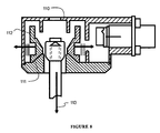
- FIG. 8 is a cutaway side view showing an inclined sliding surface according to some embodiments of the present invention.
- a release apparatus 10 for controlling the deployment of a desired device by releasing a captured member 15 utilizes a multi-piece split spool 11 adapted to restrain the captured member 15 .
- the multi-piece spool 11 consists of three or more segments 50 which define a central bore 51 adapted to restrain a captured member 15 .
- the spool 11 consists of six segments.
- the spool consists of eight segments. As seen in cross-section in FIG. 1B , the segments of the spool are adapted to fittingly receive and axially restrain an expanded portion 18 of the captured member 15 when the segments 50 are constrained together as a unit.
- the internal area of the spool 11 in the interface area of the spool 11 with the expanded portion 18 of the captured member 15 may be conical in some embodiments.
- the internal area of the spool 11 in this region may be a cone or a partial cylinder (or a curved surface other than a cone) with an angle of 30 degrees off of the vertical axis of bore.
- the external profile of the expanded portion 18 of the captured member 15 may also be conical.
- the interface area may have a curved profile.
- the internal area of the spool may be lubricated with a dry lubricant such as molybdenum disulfide.
- a tensioned tape 12 is wrapped around the external periphery of the spool 11 .
- the tape 12 is adapted to constrain the segment 50 of the spool 11 together.
- a first end of the tape 12 may be removably fastened to one of the segments 50 of the spool 11 .
- the fastening of the tape 12 to one of the segments provides tangential restraint such that the tape may be wound under tension around the outer periphery of the spool, and also will prevent the slipping of the tape around the spool once this tension has been placed in the tape.
- the tape 12 may be a spring tempered stainless steel which is 0.2 inches wide and 0.005 inches thick. Once wound under tension, the second end 13 of the tape 12 may be secured under tension by a fuse wire locking device 14 or other restraint and release system.
- Securing the second end 13 of the tape may be done to itself or to an external support, not shown in this embodiment.
- Segments 50 of spool 11 may be prevented from rotation by use of anti-rotation pins between each segment, or by other means.
- the tape 12 is wound with its successive layers over each other in plane. This allows for a much more compact overall design, in the direction of the axis of the spool, of the release device compared to previous designs. Thus, the height of the housing 16 may be kept to a minimum.
- FIG. 2 illustrates the release apparatus with the tape 12 in relaxed, unwound position. This position is reached after the release of the second end 13 of the tape 12 .
- the captured member 15 is under tension axially.
- the axial pull by the captured member forces the segments of the spool outward in a radial direction.
- the tape 12 has remained in plane and has released and unwound in an orderly fashion.
- the segments of the spool 11 are seen in a position further from the center axis of the constrained spool.
- the overlaying tape Another advantage of the overlaying tape is that the tape layers have friction between them, and thus the tension on the tape is reduced in the radially outward direction with each successive wrap.
- the tension, therefore, on the release mechanism may be significantly lower than the tension at the center of the tape.
- a release device such as a fuse, with a low load capability may be used to release the tape.
- FIGS. 3A-B and 4 A-B illustrate a contrast between a two segment spool system 30 and a multi-piece spool system 40 .
- the two segment system 30 consists of two segments 31 , 32 which define a central bore 39 .
- An interface surface 33 is adapted to interface with the expanded portion of a restrained member and to restrain its axial motion.
- the restrained member will typically be placed under tension.
- the tension along the axis of the bore of the spool will result in both axial and radial loading of the spool segments due to the conical profile of the interface surface 33 of the spool segments 31 , 32 .
- the radial loading of the spool segments will be initially be countered by the wound tape as described above.
- the spool segments must move a distance 37 sufficient to allow for the outer diameter 34 of the expanded portion of the restrained member to pass through the bore in the axial direction.
- the axial force which in turn drives the separation of the segments, becomes concentrated on the comers 36 of the segments.
- the force may be concentrated on just four points. With more force concentrated on each point, the possibility of galling and sticking at a single point, with a resulting failure to release the restrained member, is enhanced.
- the distance 37 that the segments must move is at a maximum.
- a six piece spool system 40 consists of six spool segments 41 , 42 , 43 , 44 , 45 , 46 .
- the interface surface 47 is broken into six separate pieces.
- the spool segments must move a distance 49 sufficient to allow for the outer diameter 34 of the expanded portion of the restrained member to pass through the bore in the axial direction.
- the axial force which in turn drives the separation of the segments, will be spread across the segments.
- the distance 49 that the segments 41 , 42 , 43 , 44 , 45 , 46 must travel in order to allow the passage of the expanded portion of the restrained member is significantly less than with a two segment spool.
- the differential offset 51 in between the depth of the segment bore and the diameter of the expanded portion of the restrained member in the multi-piece spool system is significantly smaller than the differential offset 52 in the two piece spool system. This gives the multi-piece spool the distinct advantage of requiring less radial travel distance for each segment in order to release the captured member.
- the use of a full circumferential spool reduces the contact forces in the interface area of the spool segments and the expanded portion of the restrained member.
- FIGS. 5A-B illustrate a release system according to some embodiments of the present invention.
- a release apparatus 60 may control the deployment of a selected device by releasing a captured member 70 .
- a multi-piece split spool 67 consists of six segments 74 which define a central bore 75 .
- the central bore 75 is sized such that the expanded portion 71 of the captured member 70 is constrained from downward axial motion by the interface portion of the segments 74 of the spool 67 .
- the segments 74 of the spool 67 are constrained from motion in the external radial direction by a wound restraining tape 63 .
- a first end 65 of the tape 63 may be constrained from motion along the exterior of the spool by attachment to one of the segments of the spool.
- a second end of the tape 66 may be constrained by a fuse wire release device 69 or other means.
- the housing 61 is low profile due to the use of an overlapping tape as the spool restraint.
- the housing 61 may include a wall 72 adapted to separate the spool and tape from the electrical interface portion 68 of the system.
- the housing 61 may have a circular inner profile 64 adapted to reduce the likelihood that the tape, as it unwinds and expands radially during the release cycle, will hang up on any inner surfaces.
- Vertical members 76 may be in place to further separate the inner compartment.
- the base 62 is of sufficient strength that it may withstand the axial force of the captured member.
- the base 62 may also provide the sliding surface upon which the spool segments move upon release of the tension in the tape.
- the base bore 73 is sized such that the expanded portion 71 of the captured member 70 may pass through the base bore upon release.
- the captured member 70 may be a rod with a threaded interface for connection into a larger system.
- the surface 77 upon which the spool segments slide in this embodiment is a flat surface, as are the bottoms of the spool segments.
- the sliding surface and the bottoms of the spool segments may have different geometries is other embodiments.
- the tape may be placed under tension by winding the tape around the spool with the bore in a horizontal position and the tape extended and under load.
- a feature may be added to prevent rotation of the spool segments while under the torsional load that may be placed upon them by the wound tape 107 .
- the spool 100 is seen made up of four segments 101 in this embodiment.
- Anti-rotational pins 102 are located between the segments 101 and are affixed to the base plate 106 of the apparatus. The pins 102 are adapted to prevent rotation of the segments 101 yet do not interfere with the outward motion of the segments upon their release.
- the tape may be anchored on a first end in a slot 103 in a spool segment 101 adapted to receive the tape 107 .
- the second end of the tape may anchored to a fuse link 105 , which may be attached to an insulator which is secured to the base plate of the housing in some embodiments.
- the geometry of the bottom of the spool segments, and of the surface upon which they slide during release, are altered in order to facilitate the release.
- the release apparatus 110 may have a spool whose segments 112 have an inclined bottom surface 111 .
- An advantage of this inclined surface is that the frictional component along the surface is lower than would be experienced with a perpendicular sliding surface, such as seen in FIG. 5B .
- the force 113 in the rod being released has a component along the incline, which facilitates the outward motion of the spool segments necessary for release.
- the release apparatus 120 uses a pivoting motion as opposed to a sliding motion.
- the spool segments 121 may have a rounded bottom 122 which is adapted to pivot within a slot 123 upon release of the tension device constraining the spool.
- the bottom of the spool segments may be circular as viewed from the top, in accord with the external periphery of the segments in the are where the tension device is wound.
- the bottom of the spool segments may be linear, such that the pivot lies in a linear slot.
- the spool segments may come to a rounded point.
Abstract
Description
Claims (6)
Priority Applications (2)
| Application Number | Priority Date | Filing Date | Title |
|---|---|---|---|
| US12/082,818 US8568053B2 (en) | 2008-04-14 | 2008-04-14 | Radial release device |
| US14/012,915 US9708082B2 (en) | 2008-04-14 | 2013-08-28 | Radial release device |
Applications Claiming Priority (1)
| Application Number | Priority Date | Filing Date | Title |
|---|---|---|---|
| US12/082,818 US8568053B2 (en) | 2008-04-14 | 2008-04-14 | Radial release device |
Related Child Applications (1)
| Application Number | Title | Priority Date | Filing Date |
|---|---|---|---|
| US14/012,915 Continuation US9708082B2 (en) | 2008-04-14 | 2013-08-28 | Radial release device |
Publications (2)
| Publication Number | Publication Date |
|---|---|
| US20100005913A1 US20100005913A1 (en) | 2010-01-14 |
| US8568053B2 true US8568053B2 (en) | 2013-10-29 |
Family
ID=41503926
Family Applications (2)
| Application Number | Title | Priority Date | Filing Date |
|---|---|---|---|
| US12/082,818 Active 2029-04-20 US8568053B2 (en) | 2008-04-14 | 2008-04-14 | Radial release device |
| US14/012,915 Active 2028-12-20 US9708082B2 (en) | 2008-04-14 | 2013-08-28 | Radial release device |
Family Applications After (1)
| Application Number | Title | Priority Date | Filing Date |
|---|---|---|---|
| US14/012,915 Active 2028-12-20 US9708082B2 (en) | 2008-04-14 | 2013-08-28 | Radial release device |
Country Status (1)
| Country | Link |
|---|---|
| US (2) | US8568053B2 (en) |
Cited By (12)
| Publication number | Priority date | Publication date | Assignee | Title |
|---|---|---|---|---|
| US20100089189A1 (en) * | 2004-08-02 | 2010-04-15 | Edward Rudoy | High load release device |
| US20140016992A1 (en) * | 2008-04-14 | 2014-01-16 | Space Systems/Loral, Llc | Radial release device |
| US9761401B1 (en) * | 2016-08-27 | 2017-09-12 | Glenair, Inc. | Hold-down release apparatus and methods incorporating a fuse wire |
| US20170349303A1 (en) * | 2014-12-26 | 2017-12-07 | Kawasaki Jukogyo Kabushiki Kaisha | Separation device |
| US10029809B1 (en) * | 2016-09-29 | 2018-07-24 | Glenair, Inc. | Retention sleeve with rolling bearings in a hold-down release apparatus |
| US10062537B1 (en) * | 2016-09-29 | 2018-08-28 | Glenair, Inc. | Redundant fuse wires in a hold-down release apparatus |
| RU2669246C1 (en) * | 2017-11-09 | 2018-10-09 | Российская Федерация, от имени которой выступает Государственная корпорация по космической деятельности "РОСКОСМОС" | Device for holding and releasing transformed mechanical systems of spacecraft |
| US10435182B1 (en) * | 2016-09-12 | 2019-10-08 | Space Systems/Loral, Llc | Articulation techniques for a spacecraft solar array |
| RU2716606C2 (en) * | 2017-12-11 | 2020-03-13 | Акционерное общество "Информационные спутниковые системы" имени академика М.Ф. Решетнёва" | Device for holding elements of power structure of spacecraft |
| CN111422382A (en) * | 2020-03-30 | 2020-07-17 | 哈尔滨工业大学 | Connection and separation device based on memory alloy wire drive |
| RU2741816C1 (en) * | 2020-07-17 | 2021-01-28 | Акционерное общество «Информационные спутниковые системы» имени академика М.Ф.Решетнёва» | Mechanical fixing device |
| AT523519B1 (en) * | 2020-05-14 | 2021-09-15 | Space Lock Gmbh | Device for holding back and for commanded release of an element to be released in the release direction |
Families Citing this family (8)
| Publication number | Priority date | Publication date | Assignee | Title |
|---|---|---|---|---|
| AT509988B1 (en) * | 2010-08-16 | 2012-01-15 | Ruag Space Gmbh | DEVICE FOR CONTACTING ELECTRICALLY AND MECHANICALLY HOLDING THE ENDS OF A TORQUE WIRE IN A RELEASE DEVICE FOR PRE-TIGHTENED BACKREST ELEMENTS IN SPACE VEHICLES |
| AT509989B1 (en) * | 2010-08-16 | 2012-01-15 | Ruag Space Gmbh | DEVICE FOR HOLDING AND COMMANDED RELEASING A RELEASE ELEMENT OF A SPACE VEHICLE |
| AT510026B1 (en) * | 2010-08-16 | 2012-01-15 | Ruag Space Gmbh | DEVICE FOR RELEASING PRE-LOADED RETENTION DEVICES IN SPACE VEHICLES |
| US9604738B2 (en) * | 2013-08-15 | 2017-03-28 | Cooper Technologies Company | Non-explosive tension release actuator |
| FR3061353B1 (en) * | 2016-12-22 | 2019-05-10 | Saft | SELF-ACTIVATION DEVICE FOR ELECTROMECHANICAL SWITCH |
| CN107972893A (en) * | 2017-11-24 | 2018-05-01 | 北京宇航系统工程研究所 | The expanding unit and method of a kind of space mechanism |
| RU2716605C2 (en) * | 2017-12-11 | 2020-03-13 | Акционерное общество "Информационные спутниковые системы" имени академика М.Ф. Решетнёва" | Trigger device |
| CN112918704B (en) * | 2021-01-22 | 2022-07-12 | 中国科学院沈阳自动化研究所 | Mechanism for optimizing spacecraft solar sailboard to overcome rocket launching mechanical environment |
Citations (14)
| Publication number | Priority date | Publication date | Assignee | Title |
|---|---|---|---|---|
| US1337642A (en) | 1918-12-04 | 1920-04-20 | Clark Charles Haskell | Shaft-coupling |
| US4638608A (en) | 1985-10-07 | 1987-01-27 | Precisionform, Inc. | Breakaway standard support assembly |
| US5282709A (en) | 1993-05-04 | 1994-02-01 | G & H Technology, Inc. | Separation nut with a restraining wire |
| US5471888A (en) * | 1994-04-12 | 1995-12-05 | G & H Technology, Inc. | Motion initiator |
| US5716157A (en) | 1994-12-14 | 1998-02-10 | Fokker Space & Systems B.V. | System for holding together and separating parts of a construction |
| US6073914A (en) * | 1996-11-30 | 2000-06-13 | Daimler-Benz Aerospace Ag | Release apparatus for a holddown device |
| US6133818A (en) * | 1999-08-11 | 2000-10-17 | Space Systems/Loral, Inc. | Redundant fuse wire release device |
| US6249063B1 (en) | 1998-03-17 | 2001-06-19 | Nea Electronics, Inc. | Battery cell bypass with frangible actuator |
| US6433990B1 (en) * | 2000-02-02 | 2002-08-13 | Nea Electronics, Inc. | Frangible actuator with redundant power supply |
| US6525920B2 (en) * | 2000-04-13 | 2003-02-25 | Nea Electronics, Inc. | Electrically and mechanically redundant release mechanism |
| US20030076215A1 (en) * | 2001-10-22 | 2003-04-24 | Baghdasarian Varouj G. | Inverted split-spool release devices |
| US6747541B1 (en) | 2002-12-06 | 2004-06-08 | G&H Technology, Inc. | Spool assembly with integrated link-wire and electrical terminals for non-explosive actuators used in electro-mechanical structural separation devices |
| US20100089189A1 (en) * | 2004-08-02 | 2010-04-15 | Edward Rudoy | High load release device |
| US8021069B2 (en) * | 2008-06-23 | 2011-09-20 | Space Systems/Loral, Inc. | Redundant radial release apparatus |
Family Cites Families (2)
| Publication number | Priority date | Publication date | Assignee | Title |
|---|---|---|---|---|
| JP4339167B2 (en) * | 2004-04-07 | 2009-10-07 | 本田技研工業株式会社 | Fastening device |
| US8568053B2 (en) * | 2008-04-14 | 2013-10-29 | Space Systems/Loral, Llc | Radial release device |
-
2008
- 2008-04-14 US US12/082,818 patent/US8568053B2/en active Active
-
2013
- 2013-08-28 US US14/012,915 patent/US9708082B2/en active Active
Patent Citations (14)
| Publication number | Priority date | Publication date | Assignee | Title |
|---|---|---|---|---|
| US1337642A (en) | 1918-12-04 | 1920-04-20 | Clark Charles Haskell | Shaft-coupling |
| US4638608A (en) | 1985-10-07 | 1987-01-27 | Precisionform, Inc. | Breakaway standard support assembly |
| US5282709A (en) | 1993-05-04 | 1994-02-01 | G & H Technology, Inc. | Separation nut with a restraining wire |
| US5471888A (en) * | 1994-04-12 | 1995-12-05 | G & H Technology, Inc. | Motion initiator |
| US5716157A (en) | 1994-12-14 | 1998-02-10 | Fokker Space & Systems B.V. | System for holding together and separating parts of a construction |
| US6073914A (en) * | 1996-11-30 | 2000-06-13 | Daimler-Benz Aerospace Ag | Release apparatus for a holddown device |
| US6249063B1 (en) | 1998-03-17 | 2001-06-19 | Nea Electronics, Inc. | Battery cell bypass with frangible actuator |
| US6133818A (en) * | 1999-08-11 | 2000-10-17 | Space Systems/Loral, Inc. | Redundant fuse wire release device |
| US6433990B1 (en) * | 2000-02-02 | 2002-08-13 | Nea Electronics, Inc. | Frangible actuator with redundant power supply |
| US6525920B2 (en) * | 2000-04-13 | 2003-02-25 | Nea Electronics, Inc. | Electrically and mechanically redundant release mechanism |
| US20030076215A1 (en) * | 2001-10-22 | 2003-04-24 | Baghdasarian Varouj G. | Inverted split-spool release devices |
| US6747541B1 (en) | 2002-12-06 | 2004-06-08 | G&H Technology, Inc. | Spool assembly with integrated link-wire and electrical terminals for non-explosive actuators used in electro-mechanical structural separation devices |
| US20100089189A1 (en) * | 2004-08-02 | 2010-04-15 | Edward Rudoy | High load release device |
| US8021069B2 (en) * | 2008-06-23 | 2011-09-20 | Space Systems/Loral, Inc. | Redundant radial release apparatus |
Non-Patent Citations (2)
| Title |
|---|
| U.S. Notice of Allowance dated May 18, 2011 issued in U.S. Appl. No. 12/215,041. |
| U.S. Notice of Allowance dated Oct. 19, 2010 issued in U.S. Appl. No. 12/215,041. |
Cited By (19)
| Publication number | Priority date | Publication date | Assignee | Title |
|---|---|---|---|---|
| US8904889B2 (en) * | 2004-08-02 | 2014-12-09 | Nea Electronics, Inc. | High load release device |
| US9870022B2 (en) | 2004-08-02 | 2018-01-16 | Ensign-Bickford Aerospace & Defense Company | High load release device |
| US20100089189A1 (en) * | 2004-08-02 | 2010-04-15 | Edward Rudoy | High load release device |
| US20140016992A1 (en) * | 2008-04-14 | 2014-01-16 | Space Systems/Loral, Llc | Radial release device |
| US9708082B2 (en) * | 2008-04-14 | 2017-07-18 | Space Systems/Loral, Llc | Radial release device |
| US20170349303A1 (en) * | 2014-12-26 | 2017-12-07 | Kawasaki Jukogyo Kabushiki Kaisha | Separation device |
| US10577134B2 (en) * | 2014-12-26 | 2020-03-03 | Kawasaki Jukogyo Kabushiki Kaisha | Separation device |
| US9761401B1 (en) * | 2016-08-27 | 2017-09-12 | Glenair, Inc. | Hold-down release apparatus and methods incorporating a fuse wire |
| US10435182B1 (en) * | 2016-09-12 | 2019-10-08 | Space Systems/Loral, Llc | Articulation techniques for a spacecraft solar array |
| US10062537B1 (en) * | 2016-09-29 | 2018-08-28 | Glenair, Inc. | Redundant fuse wires in a hold-down release apparatus |
| US10029809B1 (en) * | 2016-09-29 | 2018-07-24 | Glenair, Inc. | Retention sleeve with rolling bearings in a hold-down release apparatus |
| RU2669246C1 (en) * | 2017-11-09 | 2018-10-09 | Российская Федерация, от имени которой выступает Государственная корпорация по космической деятельности "РОСКОСМОС" | Device for holding and releasing transformed mechanical systems of spacecraft |
| RU2716606C2 (en) * | 2017-12-11 | 2020-03-13 | Акционерное общество "Информационные спутниковые системы" имени академика М.Ф. Решетнёва" | Device for holding elements of power structure of spacecraft |
| CN111422382A (en) * | 2020-03-30 | 2020-07-17 | 哈尔滨工业大学 | Connection and separation device based on memory alloy wire drive |
| CN111422382B (en) * | 2020-03-30 | 2021-07-20 | 哈尔滨工业大学 | Connection and separation device based on memory alloy wire drive |
| AT523519B1 (en) * | 2020-05-14 | 2021-09-15 | Space Lock Gmbh | Device for holding back and for commanded release of an element to be released in the release direction |
| AT523519A4 (en) * | 2020-05-14 | 2021-09-15 | Space Lock Gmbh | Device for holding back and for commanded release of an element to be released in the release direction |
| EP3909865A1 (en) | 2020-05-14 | 2021-11-17 | Space-Lock GmbH | Device for retaining and commanded release of an element to be released in the release direction |
| RU2741816C1 (en) * | 2020-07-17 | 2021-01-28 | Акционерное общество «Информационные спутниковые системы» имени академика М.Ф.Решетнёва» | Mechanical fixing device |
Also Published As
| Publication number | Publication date |
|---|---|
| US9708082B2 (en) | 2017-07-18 |
| US20140016992A1 (en) | 2014-01-16 |
| US20100005913A1 (en) | 2010-01-14 |
Similar Documents
| Publication | Publication Date | Title |
|---|---|---|
| US8568053B2 (en) | Radial release device | |
| US8021069B2 (en) | Redundant radial release apparatus | |
| JP6623004B2 (en) | Deployable mast with spontaneous autonomous deployment and satellite with at least one mast of this kind | |
| EP3480885A1 (en) | Deployable antenna reflector | |
| US9822544B2 (en) | Monopole tower reinforcement system | |
| CN107954006B (en) | Rigid belt releasing device | |
| US6761331B2 (en) | Missile having deployment mechanism for stowable fins | |
| US20110163487A1 (en) | Linear filament compression and torsion spring | |
| US8770522B1 (en) | Deployable space boom using bi-stable tape spring mechanism | |
| US8167247B2 (en) | Space-based occulter | |
| US3978490A (en) | Furlable antenna | |
| US9870022B2 (en) | High load release device | |
| US9180982B2 (en) | Preload releasing fastener and release system using same | |
| US7416158B2 (en) | Continuous disreefing apparatus for parachute | |
| CN101918082A (en) | Fall arrest system safety device | |
| US10544781B2 (en) | Elastic energy storage and deployment system | |
| US20180034254A1 (en) | Mounting device for an elongate flexible member | |
| EP3598576B1 (en) | Reflecting systems, such as reflector antenna systems, with tension-stabilized reflector positional apparatus | |
| US10017198B1 (en) | Trash bag caddy | |
| US20030076215A1 (en) | Inverted split-spool release devices | |
| EP3732096A1 (en) | Deployable submarine device | |
| US4330895A (en) | Stabilizer for reducing motion of an object disposed in a fluid | |
| CN113044248A (en) | Small-size space tether system unfolding brake mechanism adopting spinning shaft sleeve | |
| US9677602B1 (en) | Caging mechanism for a single- or multi-axis positioning mechanism | |
| CN109983298A (en) | Tape measure with the epicyclic gear driving device withdrawn for tape |
Legal Events
| Date | Code | Title | Description |
|---|---|---|---|
| AS | Assignment |
Owner name: SPACE SYSTEMS/LORAL, CALIFORNIA Free format text: ASSIGNMENT OF ASSIGNORS INTEREST;ASSIGNOR:BAGHDASARIAN, VAROUJ G.;REEL/FRAME:026385/0350 Effective date: 20110527 |
|
| AS | Assignment |
Owner name: SPACE SYSTEMS/LORAL, LLC, CALIFORNIA Free format text: CHANGE OF NAME;ASSIGNOR:SPACE SYSTEMS/LORAL, INC.;REEL/FRAME:030292/0183 Effective date: 20121102 |
|
| AS | Assignment |
Owner name: ROYAL BANK OF CANADA, CANADA Free format text: SECURITY AGREEMENT;ASSIGNOR:SPACE SYSTEMS/LORAL, LLC;REEL/FRAME:030312/0078 Effective date: 20121102 |
|
| AS | Assignment |
Owner name: SPACE SYSTEMS/LORAL, LLC, CALIFORNIA Free format text: ASSIGNMENT OF ASSIGNORS INTEREST;ASSIGNOR:BAGHDASARIAN, VAROUJ G.;REEL/FRAME:030664/0572 Effective date: 20130620 |
|
| STCF | Information on status: patent grant |
Free format text: PATENTED CASE |
|
| FPAY | Fee payment |
Year of fee payment: 4 |
|
| AS | Assignment |
Owner name: ROYAL BANK OF CANADA, AS THE COLLATERAL AGENT, CANADA Free format text: SECURITY INTEREST;ASSIGNORS:DIGITALGLOBE, INC.;MACDONALD, DETTWILER AND ASSOCIATES LTD.;MACDONALD, DETTWILER AND ASSOCIATES CORPORATION;AND OTHERS;REEL/FRAME:044167/0396 Effective date: 20171005 Owner name: ROYAL BANK OF CANADA, AS THE COLLATERAL AGENT, CAN Free format text: SECURITY INTEREST;ASSIGNORS:DIGITALGLOBE, INC.;MACDONALD, DETTWILER AND ASSOCIATES LTD.;MACDONALD, DETTWILER AND ASSOCIATES CORPORATION;AND OTHERS;REEL/FRAME:044167/0396 Effective date: 20171005 |
|
| AS | Assignment |
Owner name: ROYAL BANK OF CANADA, AS COLLATERAL AGENT, CANADA Free format text: AMENDED AND RESTATED U.S. PATENT AND TRADEMARK SECURITY AGREEMENT;ASSIGNOR:SPACE SYSTEMS/LORAL, LLC;REEL/FRAME:051258/0720 Effective date: 20191211 |
|
| AS | Assignment |
Owner name: WILMINGTON TRUST, NATIONAL ASSOCIATION, - AS NOTES Free format text: SECURITY AGREEMENT (NOTES);ASSIGNORS:DIGITALGLOBE, INC.;RADIANT GEOSPATIAL SOLUTIONS LLC;SPACE SYSTEMS/LORAL, LLC (F/K/A SPACE SYSTEMS/LORAL INC.);REEL/FRAME:051262/0824 Effective date: 20191211 Owner name: WILMINGTON TRUST, NATIONAL ASSOCIATION, - AS NOTES COLLATERAL AGENT, TEXAS Free format text: SECURITY AGREEMENT (NOTES);ASSIGNORS:DIGITALGLOBE, INC.;RADIANT GEOSPATIAL SOLUTIONS LLC;SPACE SYSTEMS/LORAL, LLC (F/K/A SPACE SYSTEMS/LORAL INC.);REEL/FRAME:051262/0824 Effective date: 20191211 |
|
| AS | Assignment |
Owner name: WILMINGTON TRUST, NATIONAL ASSOCIATION, AS NOTES COLLATERAL AGENT, CONNECTICUT Free format text: PATENT SECURITY AGREEMENT;ASSIGNOR:SPACE SYSTEMS/LORAL, LLC;REEL/FRAME:053866/0810 Effective date: 20200922 |
|
| MAFP | Maintenance fee payment |
Free format text: PAYMENT OF MAINTENANCE FEE, 8TH YEAR, LARGE ENTITY (ORIGINAL EVENT CODE: M1552); ENTITY STATUS OF PATENT OWNER: LARGE ENTITY Year of fee payment: 8 |
|
| AS | Assignment |
Owner name: ROYAL BANK OF CANADA, CANADA Free format text: SECURITY AGREEMENT;ASSIGNORS:MAXAR INTELLIGENCE INC.;MAXAR SPACE LLC;REEL/FRAME:060389/0720 Effective date: 20220614 |
|
| AS | Assignment |
Owner name: WILMINGTON TRUST, NATIONAL ASSOCIATION, TEXAS Free format text: SECURITY AGREEMENT;ASSIGNORS:MAXAR INTELLIGENCE INC.;MAXAR SPACE LLC;REEL/FRAME:060389/0782 Effective date: 20220614 |
|
| AS | Assignment |
Owner name: RADIANT GEOSPATIAL SOLUTIONS LLC, COLORADO Free format text: RELEASE BY SECURED PARTY;ASSIGNOR:WILMINGTON TRUST, NATIONAL ASSOCIATION;REEL/FRAME:060390/0282 Effective date: 20220614 Owner name: SPACE SYSTEMS/LORAL, LLC, CALIFORNIA Free format text: RELEASE BY SECURED PARTY;ASSIGNOR:WILMINGTON TRUST, NATIONAL ASSOCIATION;REEL/FRAME:060390/0282 Effective date: 20220614 Owner name: DIGITALGLOBE, INC., COLORADO Free format text: RELEASE BY SECURED PARTY;ASSIGNOR:WILMINGTON TRUST, NATIONAL ASSOCIATION;REEL/FRAME:060390/0282 Effective date: 20220614 |
|
| AS | Assignment |
Owner name: MAXAR SPACE LLC, CALIFORNIA Free format text: TERMINATION AND RELEASE OF SECURITY INTEREST IN PATENTS AND TRADEMARKS - RELEASE OF REEL/FRAME 044167/0396;ASSIGNOR:ROYAL BANK OF CANADA, AS AGENT;REEL/FRAME:063543/0001 Effective date: 20230503 Owner name: MAXAR INTELLIGENCE INC., COLORADO Free format text: TERMINATION AND RELEASE OF SECURITY INTEREST IN PATENTS AND TRADEMARKS - RELEASE OF REEL/FRAME 044167/0396;ASSIGNOR:ROYAL BANK OF CANADA, AS AGENT;REEL/FRAME:063543/0001 Effective date: 20230503 Owner name: MAXAR SPACE LLC, CALIFORNIA Free format text: TERMINATION AND RELEASE OF PATENT SECURITY AGREEMENT - RELEASE OF REEL/FRAME 060389/0782;ASSIGNOR:WILMINGTON TRUST, NATIONAL ASSOCIATION, AS COLLATERAL AGENT;REEL/FRAME:063544/0074 Effective date: 20230503 Owner name: MAXAR INTELLIGENCE INC., COLORADO Free format text: TERMINATION AND RELEASE OF PATENT SECURITY AGREEMENT - RELEASE OF REEL/FRAME 060389/0782;ASSIGNOR:WILMINGTON TRUST, NATIONAL ASSOCIATION, AS COLLATERAL AGENT;REEL/FRAME:063544/0074 Effective date: 20230503 Owner name: MAXAR SPACE LLC, CALIFORNIA Free format text: TERMINATION AND RELEASE OF SECURITY INTEREST IN PATENTS AND TRADEMARKS - RELEASE OF REEL/FRAME 051258/0720;ASSIGNOR:ROYAL BANK OF CANADA, AS AGENT;REEL/FRAME:063542/0543 Effective date: 20230503 Owner name: MAXAR INTELLIGENCE INC., COLORADO Free format text: TERMINATION AND RELEASE OF SECURITY INTEREST IN PATENTS AND TRADEMARKS - RELEASE OF REEL/FRAME 051258/0720;ASSIGNOR:ROYAL BANK OF CANADA, AS AGENT;REEL/FRAME:063542/0543 Effective date: 20230503 |
|
| AS | Assignment |
Owner name: SIXTH STREET LENDING PARTNERS, AS ADMINISTRATIVE AGENT, TEXAS Free format text: INTELLECTUAL PROPERTY SECURITY AGREEMENT;ASSIGNORS:MAXAR INTELLIGENCE INC. (F/K/A DIGITALGLOBE, INC.);AURORA INSIGHT INC.;MAXAR MISSION SOLUTIONS INC. ((F/K/A RADIANT MISSION SOLUTIONS INC. (F/K/A THE RADIANT GROUP, INC.));AND OTHERS;REEL/FRAME:063660/0138 Effective date: 20230503 |
|
| AS | Assignment |
Owner name: MAXAR INTELLIGENCE INC., COLORADO Free format text: RELEASE (REEL 060389/FRAME 0720);ASSIGNOR:ROYAL BANK OF CANADA;REEL/FRAME:063633/0431 Effective date: 20230503 Owner name: MAXAR SPACE LLC, CALIFORNIA Free format text: RELEASE (REEL 060389/FRAME 0720);ASSIGNOR:ROYAL BANK OF CANADA;REEL/FRAME:063633/0431 Effective date: 20230503 |
|
| AS | Assignment |
Owner name: MAXAR SPACE LLC, CALIFORNIA Free format text: CHANGE OF NAME;ASSIGNOR:SPACE SYSTEMS/LORAL, LLC;REEL/FRAME:063861/0016 Effective date: 20210101 |