US8606340B2 - Multi-display mobile device - Google Patents
Multi-display mobile device Download PDFInfo
- Publication number
- US8606340B2 US8606340B2 US12/951,615 US95161510A US8606340B2 US 8606340 B2 US8606340 B2 US 8606340B2 US 95161510 A US95161510 A US 95161510A US 8606340 B2 US8606340 B2 US 8606340B2
- Authority
- US
- United States
- Prior art keywords
- mobile device
- front surface
- display screen
- accept
- respect
- Prior art date
- Legal status (The legal status is an assumption and is not a legal conclusion. Google has not performed a legal analysis and makes no representation as to the accuracy of the status listed.)
- Active, expires
Links
Images


Classifications
-
- H—ELECTRICITY
- H04—ELECTRIC COMMUNICATION TECHNIQUE
- H04M—TELEPHONIC COMMUNICATION
- H04M1/00—Substation equipment, e.g. for use by subscribers
- H04M1/02—Constructional features of telephone sets
- H04M1/0202—Portable telephone sets, e.g. cordless phones, mobile phones or bar type handsets
- H04M1/0206—Portable telephones comprising a plurality of mechanically joined movable body parts, e.g. hinged housings
- H04M1/0247—Portable telephones comprising a plurality of mechanically joined movable body parts, e.g. hinged housings comprising more than two body parts
-
- G—PHYSICS
- G06—COMPUTING; CALCULATING OR COUNTING
- G06F—ELECTRIC DIGITAL DATA PROCESSING
- G06F1/00—Details not covered by groups G06F3/00 - G06F13/00 and G06F21/00
- G06F1/16—Constructional details or arrangements
- G06F1/1613—Constructional details or arrangements for portable computers
- G06F1/1615—Constructional details or arrangements for portable computers with several enclosures having relative motions, each enclosure supporting at least one I/O or computing function
- G06F1/1616—Constructional details or arrangements for portable computers with several enclosures having relative motions, each enclosure supporting at least one I/O or computing function with folding flat displays, e.g. laptop computers or notebooks having a clamshell configuration, with body parts pivoting to an open position around an axis parallel to the plane they define in closed position
-
- G—PHYSICS
- G06—COMPUTING; CALCULATING OR COUNTING
- G06F—ELECTRIC DIGITAL DATA PROCESSING
- G06F1/00—Details not covered by groups G06F3/00 - G06F13/00 and G06F21/00
- G06F1/16—Constructional details or arrangements
- G06F1/1613—Constructional details or arrangements for portable computers
- G06F1/1633—Constructional details or arrangements of portable computers not specific to the type of enclosures covered by groups G06F1/1615 - G06F1/1626
- G06F1/1637—Details related to the display arrangement, including those related to the mounting of the display in the housing
- G06F1/1641—Details related to the display arrangement, including those related to the mounting of the display in the housing the display being formed by a plurality of foldable display components
-
- G—PHYSICS
- G06—COMPUTING; CALCULATING OR COUNTING
- G06F—ELECTRIC DIGITAL DATA PROCESSING
- G06F1/00—Details not covered by groups G06F3/00 - G06F13/00 and G06F21/00
- G06F1/16—Constructional details or arrangements
- G06F1/1613—Constructional details or arrangements for portable computers
- G06F1/1633—Constructional details or arrangements of portable computers not specific to the type of enclosures covered by groups G06F1/1615 - G06F1/1626
- G06F1/1637—Details related to the display arrangement, including those related to the mounting of the display in the housing
- G06F1/1647—Details related to the display arrangement, including those related to the mounting of the display in the housing including at least an additional display
-
- H—ELECTRICITY
- H04—ELECTRIC COMMUNICATION TECHNIQUE
- H04M—TELEPHONIC COMMUNICATION
- H04M1/00—Substation equipment, e.g. for use by subscribers
- H04M1/02—Constructional features of telephone sets
- H04M1/0202—Portable telephone sets, e.g. cordless phones, mobile phones or bar type handsets
- H04M1/0206—Portable telephones comprising a plurality of mechanically joined movable body parts, e.g. hinged housings
- H04M1/0208—Portable telephones comprising a plurality of mechanically joined movable body parts, e.g. hinged housings characterized by the relative motions of the body parts
- H04M1/0214—Foldable telephones, i.e. with body parts pivoting to an open position around an axis parallel to the plane they define in closed position
-
- H—ELECTRICITY
- H04—ELECTRIC COMMUNICATION TECHNIQUE
- H04M—TELEPHONIC COMMUNICATION
- H04M2250/00—Details of telephonic subscriber devices
- H04M2250/16—Details of telephonic subscriber devices including more than one display unit
Definitions
- Embodiments disclosed herein relate generally to mobile devices, and more particularly to mobile devices comprising a plurality of displays.
- Some known mobile devices are provided with multiple displays.
- some flip-style mobile devices may provide an exterior display and an interior display.
- the interior display is typically hidden when the mobile device is flipped closed.
- FIG. 1 is a block diagram of a mobile device in one example implementation
- FIG. 2 is a block diagram of a communication subsystem component of the mobile device of FIG. 1 ;
- FIG. 3 is a block diagram of a node of a wireless network
- FIG. 4A is a perspective view of a mobile device according to one example embodiment, wherein a first portion is in a first position;
- FIG. 4B is a perspective view of a mobile device according to a variant embodiment, wherein a first portion is in a first position;
- FIG. 5A is a perspective view of the mobile device of FIG. 4A , wherein the first portion is in a second position;
- FIG. 5B is a perspective view of the mobile device of FIG. 4B , wherein the first portion is in a second position;
- FIG. 6A is a perspective view of the mobile device of FIGS. 4A and 5A according to one example embodiment, wherein parts of the first portion are folded;
- FIG. 6B is a perspective view of the mobile device of FIGS. 4B and 5B according to one example embodiment, wherein parts of the first portion are folded;
- FIG. 6C is a perspective view of the mobile device of FIGS. 4A and 5A according to another example embodiment, wherein parts of the first portion and the second portion are folded;
- FIGS. 6D to 6F illustrate views of the mobile device of FIGS. 4A and 5A according to another example embodiment
- FIG. 7 is a perspective view of a mobile device according to another example embodiment, wherein a first portion is in a second position;
- FIG. 8 is a perspective view of the mobile device of FIG. 7 , wherein parts of the first portion are folded;
- FIG. 9 is a perspective view of a mobile device according to another example embodiment, wherein a first portion is in a first position
- FIG. 10 is a perspective view of the mobile device of FIG. 9 wherein the first portion is in a second position;
- FIG. 11 is a perspective view of the mobile device of FIG. 10 wherein parts of the first portion and a second portion are folded;
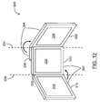
- FIG. 12 is a perspective view of a mobile device according to another example embodiment, wherein parts of a first and of a second portion are folded;
- FIG. 13 is a perspective view of a mobile device according to another example embodiment, wherein a first portion is in a second position;
- FIG. 14 is a perspective view of the mobile device of FIG. 13 wherein certain parts of the first portion and of a second portion are folded;
- FIG. 15 is a perspective view of the mobile device of FIG. 13 wherein certain parts of the first and second portions are folded;
- FIG. 16 is a perspective view of the mobile device of FIG. 13 wherein certain parts of the first and second portions are folded.
- FIG. 17 is a perspective view of the mobile device of FIG. 13 wherein certain parts of the first and second portions are folded.
- a mobile device may be a two-way communication device with advanced data communication capabilities having the capability to communicate with other computer systems.
- a mobile device may also include the capability for voice communications.
- it may be referred to as a data messaging device, a two-way pager, a cellular telephone with data messaging capabilities, a wireless Internet appliance, or a data communication device (with or without telephony capabilities), for example.
- a mobile device may communicate with other devices through a network of transceiver stations.
- FIGS. 1 through 3 To aid the reader in understanding the structure of a mobile device and how it communicates with other devices, reference is made to FIGS. 1 through 3 .
- Mobile device 100 comprises a number of components, the controlling component being microprocessor 102 .
- Microprocessor 102 controls the overall operation of mobile device 100 .
- Communication functions, including data and voice communications, may be performed through communication subsystem 104 .
- Communication subsystem 104 may be configured to receive messages from and send messages to a wireless network 200 .
- communication subsystem 104 may be configured in accordance with the Global System for Mobile Communication (GSM) and General Packet Radio Services (GPRS) standards.
- GSM Global System for Mobile Communication
- GPRS General Packet Radio Services
- the GSM/GPRS wireless network is used worldwide and it is expected that these standards may be supplemented or superseded eventually by Enhanced Data GSM Environment (EDGE) and Universal Mobile Telecommunications Service (UMTS), and Ultra Mobile Broadband (UMB), etc. New standards are still being defined, but it is believed that they will have similarities to the network behaviour described herein, and it will also be understood by persons skilled in the art that the embodiments of the present disclosure are intended to use any other suitable standards that are developed in the future.
- the wireless link connecting communication subsystem 104 with network 200 represents one or more different Radio Frequency (RF) channels, operating according to defined protocols specified for GSM/GPRS communications. With newer network protocols, these channels are capable of supporting both circuit switched voice communications and packet switched data communications.
- RF Radio Frequency
- wireless network associated with mobile device 100 is a GSM/GPRS wireless network in one example implementation of mobile device 100
- other wireless networks may also be associated with mobile device 100 in variant implementations.
- Different types of wireless networks that may be employed include, for example, data-centric wireless networks, voice-centric wireless networks, and dual-mode networks that can support both voice and data communications over the same physical base stations.
- Combined dual-mode networks include, but are not limited to, Code Division Multiple Access (CDMA) or CDMA2000 networks, GSM/GPRS networks (as mentioned above), and future third-generation (3G) networks like EDGE and UMTS.
- CDMA Code Division Multiple Access
- 3G Third-generation
- Some older examples of data-centric networks include the MobitexTM Radio Network and the DataTACTM Radio Network.
- Examples of older voice-centric data networks include Personal Communication Systems (PCS) networks like GSM and Time Division Multiple Access (TDMA) systems.
- PCS Personal Communication Systems
- TDMA Time Division Multiple Access
- Other network communication technologies that may be employed include, for example, Integrated Digital Enhanced Network (iDENTM), Evolution-Data Optimized (EV-DO), and High Speed Packet Access (HSPA), etc.
- iDENTM Integrated Digital Enhanced Network
- EV-DO Evolution-Data Optimized
- HSPA High Speed Packet Access
- Microprocessor 102 may also interact with additional subsystems such as a Random Access Memory (RAM) 106 , flash memory 108 , display 110 , auxiliary input/output (I/O) subsystem 112 , serial port 114 , keyboard 116 , speaker 118 , microphone 120 , short-range communications subsystem 122 and other device subsystems 124 .
- RAM Random Access Memory
- I/O auxiliary input/output subsystem 112
- serial port 114 serial port 114
- keyboard 116 keyboard 116
- speaker 118 microphone 120
- short-range communications subsystem 122 microphone
- Some of the subsystems of mobile device 100 perform communication-related functions, whereas other subsystems may provide “resident” or on-device functions.
- display 110 and keyboard 116 may be used for both communication-related functions, such as entering a text message for transmission over network 200 , as well as device-resident functions such as a calculator or task list.
- Operating system software used by microprocessor 102 is typically stored in a persistent store such as flash memory 108 , which may alternatively be a read-only memory (ROM) or similar storage element (not shown).
- ROM read-only memory
- Mobile device 100 may send and receive communication signals over network 200 after network registration or activation procedures have been completed. Network access may be associated with a subscriber or user of a mobile device 100 .
- mobile device 100 may provide for a Subscriber Identity Module (“SIM”) card 126 to be inserted in a SIM interface 128 in order to communicate with a network.
- SIM 126 may be one example type of a conventional “smart card” used to identify a subscriber of mobile device 100 and to personalize the mobile device 100 , among other things. Without SIM 126 , mobile device 100 may not be fully operational for communication with network 200 . By inserting SIM 126 into SIM interface 128 , a subscriber may access all subscribed services.
- SIM 126 may include a processor and memory for storing information. Once SIM 126 is inserted in SIM interface 128 , it may be coupled to microprocessor 102 . In order to identify the subscriber, SIM 126 may contain some user parameters such as an International Mobile Subscriber Identity (IMSI). By using SIM 126 , a subscriber may not necessarily be bound by any single physical mobile device. SIM 126 may store additional subscriber information for a mobile device as well, including datebook (or calendar) information and recent call information.
- IMSI International Mobile Subscriber Identity
- Mobile device 100 may be a battery-powered device and may comprise a battery interface 132 for receiving one or more rechargeable batteries 130 .
- Battery interface 132 may be coupled to a regulator (not shown), which assists battery 130 in providing power V+to mobile device 100 .
- a regulator not shown
- future technologies such as micro fuel cells may provide power to mobile device 100 .
- mobile device 100 may be solar-powered.
- Microprocessor 102 in addition to its operating system functions, enables execution of software applications on mobile device 100 .
- a set of applications that control basic device operations, including data and voice communication applications, may be installed on mobile device 100 during its manufacture.
- Another application that may be loaded onto mobile device 100 is a personal information manager (PIM).
- PIM has functionality to organize and manage data items of interest to a subscriber, such as, but not limited to, e-mail, calendar events, voice mails, appointments, and task items.
- a PIM application has the ability to send and receive data items via wireless network 200 .
- PIM data items may be seamlessly integrated, synchronized, and updated via wireless network 200 with the mobile device subscriber's corresponding data items stored and/or associated with a host computer system. This functionality may create a mirrored host computer on mobile device 100 with respect to such items. This can be particularly advantageous where the host computer system is the mobile device subscriber's office computer system.
- Additional applications may also be loaded onto mobile device 100 through network 200 , auxiliary I/O subsystem 112 , serial port 114 , short-range communications subsystem 122 , or any other suitable subsystem 124 .
- This flexibility in application installation increases the functionality of mobile device 100 and may provide enhanced on-device functions, communication-related functions, or both.
- secure communication applications may enable electronic commerce functions and other such financial transactions to be performed using mobile device 100 .
- Serial port 114 enables a subscriber to set preferences through an external device or software application and extends the capabilities of mobile device 100 by providing for information or software downloads to mobile device 100 other than through a wireless communication network.
- the alternate download path may, for example, be used to load an encryption key onto mobile device 100 through a direct and thus reliable and trusted connection to provide secure device communication.
- Short-range communications subsystem 122 provides for communication between mobile device 100 and different systems or devices, without the use of network 200 .
- subsystem 122 may include an infrared device and associated circuits and components for short-range communication.
- Examples of short range communication include standards developed by the Infrared Data Association (IrDA), Bluetooth®, and the 802.11 family of standards (Wi-Fi®) developed by IEEE.
- a received signal such as a text message, an e-mail message, or web page download is processed by communication subsystem 104 and input to microprocessor 102 .
- Microprocessor 102 then processes the received signal for output to display 110 or alternatively to auxiliary I/O subsystem 112 .
- a subscriber may also compose data items, such as e-mail messages, for example, using keyboard 116 in conjunction with display 110 and possibly auxiliary I/O subsystem 112 .
- Auxiliary subsystem 112 may include devices such as: a touch screen, mouse, track ball, optical trackpad infrared fingerprint detector, or a roller wheel with dynamic button pressing capability.
- Keyboard 116 may comprise an alphanumeric keyboard and/or telephone-type keypad, for example.
- a composed item may be transmitted over network 200 through communication subsystem 104 .
- mobile device 100 For voice communications, the overall operation of mobile device 100 may be substantially similar, except that the received signals may be processed and output to speaker 118 , and signals for transmission may be generated by microphone 120 .
- Alternative voice or audio I/O subsystems such as a voice message recording subsystem, may also be implemented on mobile device 100 .
- voice or audio signal output is accomplished primarily through speaker 118 , display 110 may also be used to provide additional information such as the identity of a calling party, duration of a voice call, or other voice call related information.
- Communication subsystem 104 may comprise a receiver 150 , a transmitter 152 , one or more embedded or internal antenna elements 154 , 156 , Local Oscillators (LOs) 158 , and a processing module such as a Digital Signal Processor (DSP) 160 .
- LOs Local Oscillators
- DSP Digital Signal Processor
- communication subsystem 104 The particular design of communication subsystem 104 is dependent upon the network 200 in which mobile device 100 is intended to operate; thus, it should be understood that the design illustrated in FIG. 2 serves only as one example.
- Signals received by antenna 154 through network 200 are input to receiver 150 , which may perform such common receiver functions as signal amplification, frequency down conversion, filtering, channel selection, and analog-to-digital (A/D) conversion. ND conversion of a received signal allows more complex communication functions such as demodulation and decoding to be performed in DSP 160 .
- signals to be transmitted are processed, including modulation and encoding, by DSP 160 .
- DSP-processed signals are input to transmitter 152 for digital-to-analog (D/A) conversion, frequency up conversion, filtering, amplification and transmission over network 200 via antenna 156 .
- DSP 160 not only processes communication signals, but also provides for receiver and transmitter control. For example, the gains applied to communication signals in receiver 150 and transmitter 152 may be adaptively controlled through automatic gain control algorithms implemented in DSP 160 .
- the wireless link between mobile device 100 and a network 200 may contain one or more different channels, typically different RF channels, and associated protocols used between mobile device 100 and network 200 .
- a RF channel is generally a limited resource, typically due to limits in overall bandwidth and limited battery power of mobile device 100 .
- transmitter 152 When mobile device 100 is fully operational, transmitter 152 may be typically keyed or turned on only when it is sending to network 200 and may otherwise be turned off to conserve resources. Similarly, receiver 150 may be periodically turned off to conserve power until it is needed to receive signals or information (if at all) during designated time periods.
- network 200 comprises one or more nodes 202 .
- Mobile device 100 communicates with a node 202 within wireless network 200 .
- node 202 is configured in accordance with GPRS and GSM technologies; however, in other embodiments, different standards may be implemented as discussed in more detail above.
- Node 202 includes a base station controller (BSC) 204 with an associated tower station 206 , a Packet Control Unit (PCU) 208 added for GPRS support in GSM, a Mobile Switching Center (MSC) 210 , a Home Location Register (HLR) 212 , a Visitor Location Registry (VLR) 214 , a Serving GPRS Support Node (SGSN) 216 , a Gateway GPRS Support Node (GGSN) 218 , and a Dynamic Host Configuration Protocol (DHCP) server 220 .
- BSC base station controller
- PCU Packet Control Unit
- MSC Mobile Switching Center
- HLR Home Location Register
- VLR Visitor Location Registry
- SGSN Serving GPRS Support Node
- GGSN Gateway GPRS Support Node
- DHCP Dynamic Host Configuration Protocol
- MSC 210 is coupled to BSC 204 and to a landline network, such as a Public Switched Telephone Network (PSTN) 222 to satisfy circuit switched requirements.
- PSTN Public Switched Telephone Network
- the connection through PCU 208 , SGSN 216 and GGSN 218 to the public or private network (Internet) 224 (also referred to herein generally as a shared network infrastructure) represents the data path for GPRS capable mobile devices.
- BSC 204 also contains a Packet Control Unit (PCU) 208 that connects to SGSN 216 to control segmentation, radio channel allocation and to satisfy packet switched requirements.
- PCU Packet Control Unit
- HLR 212 is shared between MSC 210 and SGSN 216 . Access to VLR 214 is controlled by MSC 210 .
- Station 206 may be a fixed transceiver station. Station 206 and BSC 204 together may form the fixed transceiver equipment.
- the fixed transceiver equipment provides wireless network coverage for a particular coverage area commonly referred to as a “cell”.
- the fixed transceiver equipment transmits communication signals to and receives communication signals from mobile devices within its cell via station 206 .
- the fixed transceiver equipment normally performs such functions as modulation and possibly encoding and/or encryption of signals to be transmitted to the mobile device in accordance with particular, usually predetermined, communication protocols and parameters, under control of its controller.
- the fixed transceiver equipment similarly demodulates and possibly decodes and decrypts, if necessary, any communication signals received from mobile device 100 within its cell. Communication protocols and parameters may vary between different nodes. For example, one node may employ a different modulation scheme and operate at different frequencies than other nodes.
- HLR 212 For all mobile devices 100 registered with a specific network, permanent configuration data such as a user profile may be stored in HLR 212 .
- HLR 212 may also contain location information for each registered mobile device and can be queried to determine the current location of a mobile device.
- MSC 210 is responsible for a group of location areas and stores the data of the mobile devices currently in its area of responsibility in VLR 214 .
- VLR 214 also contains information on mobile devices that are visiting other networks. The information in VLR 214 includes part of the permanent mobile device data transmitted from HLR 212 to VLR 214 for faster access. By moving additional information from a remote HLR 212 node to VLR 214 , the amount of traffic between these nodes can be reduced so that voice and data services can be provided with faster response times while requiring less use of computing resources.
- SGSN 216 and GGSN 218 are elements that may be added for GPRS support; namely packet switched data support, within GSM.
- SGSN 216 and MSC 210 have similar responsibilities within wireless network 200 by keeping track of the location of each mobile device 100 .
- SGSN 216 also performs security functions and access control for data traffic on network 200 .
- GGSN 218 provides internetworking connections with external packet switched networks and connects to one or more SGSNs 216 via an Internet Protocol (IP) backbone network operated within the network 200 .
- IP Internet Protocol
- a given mobile device 100 performs a “GPRS Attach” to acquire an IP address and to access data services.
- GPRS capable networks may use private, dynamically assigned IP addresses, thus requiring a DHCP server 220 connected to the GGSN 218 .
- RADIUS Remote Authentication Dial-In User Service
- a logical connection is established from a mobile device 100 , through PCU 208 , and SGSN 216 to an Access Point Node (APN) within GGSN 218 , for example.
- APN Access Point Node
- the APN represents a logical end of an IP tunnel that can either access direct Internet compatible services or private network connections.
- the APN also represents a security mechanism for network 200 , insofar as each mobile device 100 must be assigned to one or more APNs and mobile devices 100 cannot generally exchange data without first performing a GPRS Attach to an APN that it has been authorized to use.
- the APN may be considered to be similar to an Internet domain name such as “myconnection.wireless.com”.
- IPsec IP Security
- VPN Virtual Private Networks
- PDP Packet Data Protocol
- network 200 will run an idle timer for each PDP Context to determine if there is a lack of activity.
- the PDP Context can be deallocated and the IP address returned to the IP address pool managed by DHCP server 220 .
- a mobile device comprising a first portion slidably coupled to a second portion, wherein at least one part of the first potion is foldable with respect to at least one part of the second portion such that the mobile device resembles a picture frame comprising multiple digital displays.
- a mobile device comprising a first portion and a second portion.
- the first portion comprises a first part providing at least a first display screen, and a second part providing at least a second display screen.
- the first part is foldably coupled to the second part to allow the first part to fold with respect to the second part about a first folding axis.
- the second portion comprises a third part providing at least a third display screen.
- the first portion is slidably coupled to the second portion and at least one of the first portion and the second portion comprises one or more coupling elements configured so that the second part of the first portion is foldable with respect to the third part of the second portion about a second folding axis.
- At least two of (i) an edge of the first part, (ii) an edge of the second part, and (iii) an edge of the third part may lie in a same plane. At least one of the first folding axis and the second folding axis may be normal to the same plane. In some embodiments, all three of the edge of the first part, the edge of the second part and the edge of the third part may lie in the same plane.
- the first portion may comprise a hinge that foldably couples the first part to the second part.
- the one or more coupling elements may comprise a hinge that foldably couples the second part of the first portion to the third part of the second portion.
- the second part may provide a contact surface configured to abut the third part and to stop the second part from folding about the second folding axis with respect to the third part, after a predetermined fold angle between the second part and the third part is obtained.
- the second part may provide a beveled edge, and the beveled edge may comprise the contact surface.
- the second part may provide a contact surface configured to mate with an indent in the second portion and to stop the second part from folding about the second folding axis with respect to the third part, after a predetermined fold angle between the second part and the third part is obtained.
- the first portion may be configured to slide relative to the second portion between at least a first position and a second position.
- the third display screen When in the first position, the third display screen may be covered by the first portion, whereas in the second position, the third display screen may be at least partially exposed by the first portion.
- each of the first part, the second part, and the third part may comprise a respective front surface.
- the first display screen may be on the front surface of the first part
- the second display screen may be on the front surface of the second part
- the third display screen may be on the front surface of the third part.
- the first part may be configured to fold with respect to the second part about the first folding axis such that the front surface of the first part moves towards the front surface of the second part.
- the second part may be configured to fold with respect to the third part about a second folding axis in the second position such that the front surface of the second part moves towards the front surface of the third part.
- the respective front surfaces of the first, second and third parts may form a concave “U”-like shape, with the respective front surfaces of the first, second and third parts on the interior of the concave “U”-like shape.
- the first portion may be configured to slide with respect to the second portion in a slide direction which is perpendicular to at least one of the first folding axis and the second folding axis.
- the second portion may further comprise a fourth part, which provides at least a fourth display screen.
- the first portion may be configured to slide relative to the second portion between at least a first position and a second position; wherein in the first position, the third and fourth display screens are covered by the first portion; and wherein in the second position, at least one of the third and fourth display screens is at least partially exposed by the first portion.
- the third part of the second portion may be foldably coupled to the fourth part of the second portion to allow the third part to fold with respect to the fourth part about a third folding axis.
- the second portion may comprise a hinge that foldably couples the third part to the fourth part.
- each of the first part, the second part, the third part and the fourth part may comprise a respective front surface.
- the first display screen may be on the front surface of the first part
- the second display screen may be on the front surface of the second part
- the third display screen may be on the front surface of the third part
- the fourth display screen may be on the front surface of the fourth part.
- the first part may be configured to fold with respect to the second part about the first folding axis such that the front surface of the first part moves towards the front surface of the second part.
- the second part In the second position, the second part may be configured to fold with respect to the fourth part about a second folding axis.
- the third part may be configured to fold with respect to the fourth part about the third folding axis such that the front surface of the third part moves towards the front surface of the fourth part.
- the second part may be configured to fold with respect to the fourth part about the second folding axis in the second position such that the front surface of the second part moves away from the front surface of the fourth part, and such that the respective front surfaces of the first, second, third, and fourth parts form a “W”-like shape, with the respective front surfaces of the first, second, third and fourth parts on the interior of the “W”-like shape.
- the third display screen may provide a display area that is larger than a display area of each of the first display screen and the second display screen.
- each of the first portion and the second portion may comprise a respective front surface, wherein the front surface of the first portion and the front surface of the second portion are substantially equal in area.
- At least one of the first, second and third display screens may comprise a touch screen.
- At least one of the first, second and third display screens may be configured to accept touch screen input when the first portion is in one of the first and second positions, but to not accept touch screen input when the first portion is in one other of the first and second positions.
- the mobile device 300 may be the same kind of device as the mobile device 100 described above.
- the mobile device 300 comprises a first portion 302 and a second portion 304 , each having a respective front surface 306 , 308 .
- the first portion 302 comprises at least a first part 310 and a second part 312 .
- the first part 310 comprises a front surface 314 on which at least a first display screen 318 is provided.
- the second part 312 comprises a front surface 316 on which at least a second display screen 320 is provided.
- the second portion 304 comprises at least a third part 322 with a front surface 324 on which at least a third display screen 326 is provided.
- the first portion 302 and the second portion 304 may be of the same width and height as shown in FIG. 4A .
- the width and/or height of the first portion 302 may different from the width and/or height of the second portion 304 .
- FIGS. 4B , 5 B and 6 B illustrate a perspective view of the mobile device 300 in accordance with another example embodiment, in which the height of the second portion 304 is shortened relative to the first portion 302 .
- FIGS. 4A , 5 A and 6 A are described herein in greater detail, although persons skilled in the art will understand that the described features will also apply to the example embodiment of FIGS. 4B , 5 B, and 6 B.
- the thickness of the first portion 302 may or may not be different from the thickness of the second portion 304 .
- the thickness of a given portion may depend on the type of components housed by that portion (e.g. a battery).
- a battery compartment and/or SIM card compartment may be provided on the underside of the second portion 304 .
- the first portion 302 is in a first position.
- the user may interact with the display screens 318 and 320 .
- one display screen may be used to accept user input (e.g. a virtual keyboard may be provided on a touch screen), while the other display screen is used to view output of the mobile device 300 .
- both display screens may be configured to provide output to the user. Other configurations may be possible.
- the user may view a web page on one display screen while composing an e-mail message at the same time on a different display screen, or an initial message can be viewed in one display screen while a response is composed in another display screen
- the first portion 302 In the first position, the first portion 302 is positioned in front of the second portion 304 and completely covers the third display screen 326 ( FIG. 5A ).
- the first portion 302 is slidably coupled to the second portion 304 such that the first portion 302 can slide in a slide direction 328 to a second position (shown in FIG. 5A ) to at least partially expose the third display screen 326 .
- the third display screen 326 is fully exposed when the first portion 302 is in the second position. Slidably coupling the first portion 302 to the second portion 304 may permit the mobile device 300 to selectively take on a more compact form for transportation and storage.
- the user may interact with the three display screens 318 , 320 , 326 simultaneously, which may facilitate multitasking.
- one display screen may be used to accept user input (e.g. a virtual keyboard may be provided on a touch screen), while the other two display screens may be used to view output of the mobile device 300 .
- all three display screens may be configured to provide output to the user. Other configurations may be possible.
- the user may view a web page on one display screen while composing an e-mail message at the same time on a different display screen, or an initial message can be viewed in one display screen while a response is composed in another display screen.
- the user may interact with a different application on the third display screen.
- the coupling which permits the first portion 302 to slide with respect to the second portion 304 may be one that is known in the art.
- projections and tracks may be provided on each of the first and second portions 302 , 304 , with the projections on one portion 302 , 304 cooperating with tracks on the other portion 302 , 304 .
- the sliding mechanism may also be configured to limit the range in which first portion 302 is permitted to slide over second portion 304 .
- first portion 302 may only be permitted to slide a pre-determined distance after third display screen 326 is fully exposed (see e.g. FIG. 5A ).
- Other sliding mechanisms may be employed in variant implementations.
- the mobile device 300 is also configured to allow certain parts 310 , 312 , 322 to fold with respect to one another after the first portion 302 slides to the second position shown in FIG. 5A .
- FIG. 6A shows a perspective view of the mobile device 300 with the parts 310 , 312 , 322 folded inwardly.
- the first part 310 is foldably coupled to the second part 312 to allow the first part 310 to fold with respect to the second part 312 about a first folding axis 330 .
- At least one of the first portion 302 and the second portion 304 comprises one or more coupling elements configured so that the second part 312 is foldable with respect to the third part 322 about a second folding axis 334 .
- first part 310 and the second part 312 may be so coupled using one or more coupling elements as may be known in the art.
- a hinge 332 may couple the first part 310 and the second part 312 and permit them to fold with respect to one another.
- the first part 310 and the second part 312 may be joined by a flexible member (not shown), which is adapted to bend when the first and second parts 310 , 312 fold with respect to one another.
- the first part 310 and the second part 312 may be provided as a single liquid crystal display (LCD) or organic light emitting diode (OLED) display, which may cover a mechanical hinge coupling the first part 310 to the second part 312 . Accordingly, the first portion 302 may appear to provide one large screen that can flex so as to then appear to provide two separate screens.
- a hinge or other coupling element between the first part 310 and the second part 312 may be configured to allow the parts to fold relative to one another only up to a predetermined fold angle. Other coupling elements may be employed in variant embodiments.
- the second and third parts 312 , 322 of the first portion 302 may be foldably coupled by a second hinge 336 in some embodiments.
- the second portion may comprise a hinge which is not connected to the first portion 302 , and which enables the third part 322 to fold with respect to itself and the first part 312 .
- a hinge or other coupling element between the second part 312 and the third part 322 may be configured to allow the parts to fold relative to one another only up to a predetermined fold angle.
- the second and third parts 312 , 322 may not be hingedly coupled, and other coupling mechanisms may be employed.
- FIGS. 6D to 6F a top view, a right side view, and a perspective view of the mobile device 300 of which the parts 310 , 312 , 322 have been folded inwardly (e.g. as shown in FIG. 6A ), in accordance with another embodiment, are shown.
- These figures depict a mobile device 300 that provides coupling elements on the second portion 304 , comprising a sliding portion 360 and a retractable arm 362 .
- the sliding portion 360 may comprise a slot 364 for receiving the arm 362 prior to the folding of parts 310 , 312 , 322 (as in FIGS. 4A and 5A ).
- One or more magnets 364 may be provided on the sliding portion 360 to hold the first portion 302 substantially flat against the second portion 304 prior to folding.
- the arm 362 settles in the slot 364 of the sliding portion 360 and may further slide into a cavity (not shown) provided underneath the screen 326 within the third part 322 for storage.
- the sliding portion 360 is stored within the second portion 304 and does not yet extend beyond the top edge of the second portion 304 (see e.g. FIG. 4A ).
- the first portion 302 slides relative to the second portion 304 into a second position (see e.g. FIG.
- the arm 362 will move to occupy the end of the slot 364 towards the top end of the second portion 304 .
- the slot is dimensioned so as to permit the first portion 302 to slide relative to the second portion 304 in order to reveal the third screen 326 , but with the sliding portion 360 remaining stored within the second portion 304 such that it does not yet extend beyond the top edge of the second portion 304 (see e.g. FIG. 5A ).
- a further sliding of the first portion 302 may be performed, such that the sliding portion 360 extends from the top edge of the second portion 304 in order to release the arm 362 .
- the arm 362 is pivotally connected to the second portion 304 (or to the sliding portion 360 ), allowing the end of the second part 312 closest to the first part 310 to be elevated, and causing the end of the second part 312 closest to the third part 322 to rest on the second portion 304 (a beveled edge may be provided on the second part 312 that rests on the second portion 304 in certain embodiments), as shown in FIGS. 6E and 6F .
- the first part 310 may be folded with respect to the second part 312 to achieve a third position (see e.g. FIG. 6A ). Coupling elements may be employed and configured to hold each part in its place, in the first, second and/or third positions.
- the second part 312 and the third part 322 do not need to each comprise an edge directly aligned with a folding axis in order for them to fold with respect to one another about that folding axis.
- the second part 312 is folded with respect to the third part 322 about a third folding axis 337 even though the second part 312 does not comprises an edge which is directly in line with the third folding axis 337 .
- the parts 310 , 312 , 322 may be configured to limit the maximum amount by which they may be folded with respect to the other parts 310 , 312 , 322 .
- the second part 312 may provide a contact surface 340 configured to abut the third part 322 and to stop the second part 312 from folding about the second folding axis 334 with respect to the third part 322 .
- the size and shape of the contact surface 340 may be customized to stop the second part 312 from folding about the second folding axis 334 after a predetermined fold angle 342 between the second part 312 and the third part 322 is obtained. This may permit the second part 312 to be folded, with respect to the third part 322 , at a predetermined fold angle 342 quickly and accurately.
- the predetermined fold angle 342 may be selected to provide an optimal viewing angle for the display screens 318 , 320 , 326 , when the mobile device 300 is to be used as a picture frame, for example.
- a beveled edge on the second part 312 comprises the contact surface 340 .
- the shape and/or angle of the beveled edge may be designed to select a desired predetermined fold angle 342 .
- the second part 312 may provide a contact surface 340 configured to mate with an indent (not shown) in the second portion 304 and to stop the second part 312 from folding about the second folding axis 334 with respect to the third part 322 , after a predetermined fold angle 342 between the second part 312 and the third part 322 is obtained.
- the position and size of the indent and the contact surface 340 may be customized to selected a desired predetermined fold angle 342 .
- the parts 310 , 312 , 322 may be folded to form a concave “U”-like shape, with the respective front surfaces 314 , 316 , 324 of the first, second and third parts 310 , 312 , 322 on the interior of the concave “U”-like shape, as shown in FIG. 6A , for example.
- references herein to a concave “U”-like shape do not require adjacent parts to be at right angles to each other.
- a “U”-like shape may comprise a concave shape with each interior angle being between 0 and 90 degrees exclusively. Each angle may be the same or different from the other angle(s).
- the user may interact with the mobile device 300 using one or more of buttons (not shown), trackwheels (not shown), trackballs (not shown) or some other input device.
- one or more of the first, second and third display screens 318 , 320 , 326 may be touch screens adapted to receive touch screen input.
- all three display screens 318 , 320 , 326 may be touch screens.
- multiple applications may be executing on the mobile device 300 , and each display screen may be associated with a different application.
- a given touch screen may be configured to accept or to not accept touch screen inputs depending on the relative positions of the first and second portions 302 , 304 .
- the first and second display screens 318 , 320 may be configured to accept touch screen inputs and the third display screen 326 may be configured to not accept touch screen inputs.
- the first and second display screens 318 , 320 may be configured not to accept touch screen inputs and the third display screen 326 may be configured to accept touch screen inputs.
- the following table summarizes some of the possible ways the display screens 318 , 320 , 326 may be configured with respect to acceptance of touch screen inputs.
- the first portion 302 is configured to slide with respect to the second portion 304 in the slide direction 328 .
- the slide direction 328 may be perpendicular to one of the first folding axis 330 and the second folding axis 334 .
- the parts 310 , 312 , 322 of the first and second portion 302 , 304 may be folded, as shown in FIG. 6A , for example.
- the mobile device 300 may then be rested on its side as shown. When oriented in this configuration, the device 300 may operate as a picture frame comprising multiple digital displays, for example. This may permit the mobile device 300 to take on different functionalities.
- the mobile device 300 may be configured to operate as a mobile phone when the parts are not folded, and to operate as a picture frame (in a “digital picture frame mode”) when the parts are folded and/or when the mobile device 300 is rested on its side.
- a different digital picture may be displayed in each display, for example.
- a clock showing the time may also be displayed in a display, for example.
- digital picture frame mode may be operated automatically, when the mobile device 300 is in the state of charging.
- the mobile device 300 may be operated when the parts are folded, with the mobile device resting on the underside of the second portion 304 upon a resting surface.
- the second portion 304 may act as a base, with the third display screen 326 accessible to receive user input (e.g. via virtual keys provided on the display screen 326 ) and parallel to the resting surface (e.g. a table).
- Display screens 318 , 320 may then be folded towards the user, in a manner similar to the way a laptop might be used, except two screens are provided to display output to the user.
- the mobile device 300 may comprise sensors, configured to detect when the mobile device is turned on its side and/or folded, and the mobile device 300 may use these sensors to determine when the mobile device 300 is to operate as a picture frame in the digital picture frame mode.
- the mobile device 300 may be configured to enable or disable certain device functions when entering the digital picture frame mode. For example, when entering digital picture frame mode, the mobile device 300 may be configured to lock and disable phone functionality until the mobile device 300 is unlocked (e.g. upon a user entering a device password). This may permit a user to allow others to view the displayed pictures and to leave the mobile device 300 on their desk without risking that others will make unauthorized use of the mobile device 300 .
- the display screens 318 , 320 , 326 may be configured to accept touch screen inputs in digital picture frame mode.
- the display screens 318 , 320 , 326 may be configured to not accept touch screen inputs while the mobile device 300 is in digital picture frame mode. This may prevent a change of the photos being displayed without the authorization of the device owner or access to device functions, for example,
- At least two, of an edge 344 of the first part, an edge 346 of the second part and an edge 348 of the third part lie in the same plane 350 so that the mobile device 300 is stable and self-supporting when it is rested on a flat surface, for use as a picture frame, for example.
- all three edges 346 , 348 , 350 may lie in the same plane 350 .
- at least one of the first and second folding axes 330 , 334 may be normal to the plane 350 .
- legs or feet may be provided on one or more of the parts 310 , 312 , 322 to support the mobile device 300 when it is resting on its side.
- FIGS. 7 and 8 show perspective views of the mobile device 300 with unequally display areas, in a variant embodiment.
- FIGS. 7 and 8 show an embodiment where the third display screen 326 provides a larger display area than each of the first display screen 318 and the second display screen 320 .
- the fourth part 338 may comprise a front surface 352 on which a fourth display screen 354 is provided.
- Details provided above with respect to the three-part mobile device may be applicable by extension to a four-part mobile device, such as that illustrated in FIGS. 9 to 17 .
- details with respect to hinges, coupling elements, sliding mechanisms, digital picture frame modes, contact surfaces, touch screen inputs, alignment of edges, and sizing of parts and/or portions as previously described may be extended to the four-part mobile device embodiments described below. The reader is directed to earlier parts of the description for details.
- embodiments of the mobile device 300 having four parts may be configured to operate as a mobile device when the parts are not folded, and to operate as a picture frame (e.g. in “digital picture frame mode”) when at least some of the parts are folded relative to one another.
- the mobile device 300 may comprise sensors (not shown) configured to detect when the mobile device 300 is turned on its side and/or folded, and the mobile device 300 may use these sensors to determine when the mobile device 300 is to enter the digital picture frame mode.
- the first portion 302 is slidably coupled to the second portion 304 such that the first portion 302 can slide in a slide direction 328 to expose at least a part of the third display screen 326 ( FIG. 10 ) or to expose at least a part of both the third and fourth display screens 326 , 354 ( FIG. 13 ).
- the third display screen 326 is fully exposed and in the example shown in FIG. 13 , both the third and fourth display screens 326 , 354 are fully exposed.
- the first part 310 is foldably coupled to the second part 312 to allow the first part 310 to fold with respect to the second part 312 about the first folding axis 330 (see e.g. FIGS. 11 and 12 ). Further, at least one of the first portion 302 and the second portion 304 comprises one or more coupling elements configured so that the second part 312 is foldable with respect to the third part 322 about the second folding axis 334 (see e.g. FIGS. 11 and 12 ).
- FIG. 14 shows an embodiment where the first and second parts 310 , 312 are foldably coupled to allow the first part 310 to rotate with respect to the second part 312 about the first folding axis 330 .
- the third and fourth parts 322 , 338 of the second portion 304 may comprise one or more coupling elements, which may be configured to permit the third part 322 to fold with respect to the second and fourth parts 312 , 338 .
- the second part 312 and the fourth part 338 may not be folded with respect to each other.
- coupling elements between the second and fourth parts 312 , 338 may be configured to permit both the third and fourth parts 322 , 338 to fold with respect to the second part 312
- the coupling elements between the third and fourth parts 322 , 338 may be configured to permit the third part 322 to fold with respect to the second and fourth parts 312 , 338 , as shown in FIG. 15 .
- FIG. 16 shows an embodiment where the second and the fourth parts 312 , 338 are foldably coupled and may comprise the one or more coupling elements.
- the coupling elements may be configured to permit the third and fourth parts 322 , 338 to fold with respect to the second part 312 , even where the third part 322 is not folded with respect the fourth part 338 .
- the parts disclosed herein as being foldably coupled may be configured to fold with respect to one another by the rotation of at least one part about a folding axis.
- the rotation of the at least one part about a folding axis may be in one or both of a clockwise and a counterclockwise direction.
- the first part 310 may be configured to fold with respect to the second part 312 about the first folding axis 330 such that the front surface 314 of the first part 310 moves towards the front surface 316 of the second part 312 .
- the second part 312 may be configured to fold with respect to the fourth part 338 about a second folding axis 334 such that the front surface 316 of the second part 312 moves away from the front surface 352 of the fourth part 338 .
- the third part 322 may be configured to fold with respect to the fourth part 338 about the third folding axis 337 such that the front surface 324 of the third part 322 moves towards the front surface 352 of the fourth part 338 .
- the respective front surfaces 314 , 316 , 324 , 352 of the first, second, third and fourth parts 310 , 312 , 322 , 338 may form a “W”-like shape, with the respective front surfaces 314 , 316 , 324 , 352 on the interior of the “W”-like shape.
- first and second parts 310 , 312 of the first portion 302 may not be foldably coupled while other parts, such as the second and fourth parts 312 , 338 and/or the fourth and third parts 338 , 322 may be foldably coupled.
- the coupling elements may comprise one or more hinges 356 , 334 , for example.
- the first part 310 and the second part 312 may be joined by a flexible member (not shown), which is adapted to bend when the first and second parts 310 , 312 fold with respect to one another.
- the third part 322 and the fourth part 338 may be joined by a flexible member (not shown), which is adapted to bend when the third and fourth parts 322 , 338 fold with respect to one another.
- the first part 310 and the second part 312 may be provided as a single liquid crystal display (LCD) or organic light emitting diode (OLED) display, which may cover a mechanical hinge coupling the first part 310 to the second part 312 . Accordingly, the first portion 302 may appear to provide one large screen that can flex so as to then appear to provide two separate screens.
- a hinge or other coupling element between the first part 310 and the second part 312 may be configured to allow the parts to fold relative to one another only up to a predetermined fold angle.
- the third part 322 and the fourth part 338 may be provided as a single liquid crystal display (LCD) or organic light emitting diode (OLED) display, which may cover a mechanical hinge coupling the third part 322 to the fourth part 338 . Accordingly, the second portion 304 may appear to provide one large screen that can flex so as to then appear to provide two separate screens.
- a hinge or other coupling element between the third part 322 and the fourth part 312 may be configured to allow the parts to fold relative to one another only up to a predetermined fold angle.
- the various parts, front surfaces and display screens need not be equally sized.
- the fourth part 338 is smaller than each of the other parts 310 , 312 , 322 .
- the fourth display screen 354 and the front surface 352 of the fourth part 338 may be smaller than each of the other display screens 318 , 320 , 326 and front surfaces 314 , 316 , 324 respectively.
- one or more of the parts 310 , 312 , 322 , 338 may not comprise a display screen (not shown).
- the part may instead comprise a physical keyboard, a trackpad, or a slot for a physical picture to be inserted, for example.
- the mobile device 300 may comprise more than four parts, such as five parts or six parts. Details provided above with respect to the three-part and four-part mobile device embodiments may be applicable by extension to a mobile device with a greater number of parts.
- any portion 302 , 304 , or of any part 310 , 312 , 322 , 338 may not be square, and may be rounded and/or beveled, for example (see e.g. FIGS. 6D to 6F ).
- one or more sides of any portion 302 , 304 , or of any part 310 , 312 , 322 , 338 may be curved and/or notched, in some implementations.
- X and/or Y is intended to mean X or Y or both.
- X, Y, and/or Z is intended to mean X or Y or Z or any combination thereof.
Abstract
Description
| First Position | Second Position |
| First display | Second display | Third display | First display | Second display | Third display |
| screen (318) | screen (320) | screen (326) | screen (318) | screen (320) | screen (326) |
| Accept | Accept | Not accept | Not accept | Not accept | Not accept |
| Accept | Accept | Not accept | Not accept | Not accept | Accept |
| Accept | Accept | Not accept | Not accept | Accept | Not accept |
| Accept | Accept | Not accept | Accept | Not accept | Not accept |
| Accept | Accept | Not accept | Not accept | Accept | Accept |
| Accept | Accept | Not accept | Accept | Not accept | Accept |
| Accept | Accept | Not accept | Accept | Accept | Not accept |
| Accept | Accept | Not accept | Accept | Accept | Accept |
| Accept | Not accept | Not accept | Not accept | Not accept | Not accept |
| Accept | Not accept | Not accept | Not accept | Not accept | Accept |
| Accept | Not accept | Not accept | Not accept | Accept | Not accept |
| Accept | Not accept | Not accept | Accept | Accept | Accept |
| Accept | Not accept | Not accept | Not accept | Accept | Accept |
| Accept | Not accept | Not accept | Accept | Not accept | Accept |
| Accept | Not accept | Not accept | Accept | Accept | Not accept |
| Accept | Not accept | Not accept | Accept | Not accept | Not accept |
| Not accept | Accept | Not accept | Not accept | Not accept | Not accept |
| Not accept | Accept | Not accept | Not accept | Not accept | Accept |
| Not accept | Accept | Not accept | Accept | Accept | Accept |
| Not accept | Accept | Not accept | Accept | Not accept | Not accept |
| Not accept | Accept | Not accept | Not accept | Accept | Accept |
| Not accept | Accept | Not accept | Accept | Not accept | Accept |
| Not accept | Accept | Not accept | Accept | Accept | Not accept |
| Not accept | Accept | Not accept | Not accept | Accept | Not accept |
Claims (22)
Priority Applications (1)
| Application Number | Priority Date | Filing Date | Title |
|---|---|---|---|
| US12/951,615 US8606340B2 (en) | 2010-11-22 | 2010-11-22 | Multi-display mobile device |
Applications Claiming Priority (1)
| Application Number | Priority Date | Filing Date | Title |
|---|---|---|---|
| US12/951,615 US8606340B2 (en) | 2010-11-22 | 2010-11-22 | Multi-display mobile device |
Publications (2)
| Publication Number | Publication Date |
|---|---|
| US20120127061A1 US20120127061A1 (en) | 2012-05-24 |
| US8606340B2 true US8606340B2 (en) | 2013-12-10 |
Family
ID=46063883
Family Applications (1)
| Application Number | Title | Priority Date | Filing Date |
|---|---|---|---|
| US12/951,615 Active 2032-03-04 US8606340B2 (en) | 2010-11-22 | 2010-11-22 | Multi-display mobile device |
Country Status (1)
| Country | Link |
|---|---|
| US (1) | US8606340B2 (en) |
Cited By (16)
| Publication number | Priority date | Publication date | Assignee | Title |
|---|---|---|---|---|
| USD701862S1 (en) * | 2011-02-18 | 2014-04-01 | Lg Electronics Inc. | Cart barcode scanner |
| US9077792B1 (en) | 2014-10-28 | 2015-07-07 | Mohammad T. A. J. Alhaidar | Expandable mobile device |
| US20150241927A1 (en) * | 2008-11-24 | 2015-08-27 | Sang Kyu Ryu | Soft display device for portable terminal |
| US20150356338A1 (en) * | 2014-06-04 | 2015-12-10 | Lenovo (Singapore) Pte. Ltd. | Fingerprint reader on a portion of a device for changing the configuration of the device |
| USD757723S1 (en) * | 2013-11-25 | 2016-05-31 | Samsung Electronics Co., Ltd. | Electronic device |
| US9523964B2 (en) * | 2014-12-11 | 2016-12-20 | Shenzhen China Star Optoelectronics Technology Co., Ltd | Intelligent wristwatch |
| USD775601S1 (en) * | 2014-04-18 | 2017-01-03 | Lg Electronics Inc. | Cellular phone |
| USRE46259E1 (en) * | 2011-07-29 | 2017-01-03 | Samsung Electronics Co., Ltd. | Mobile phone monitor |
| USRE46267E1 (en) * | 2012-01-13 | 2017-01-10 | Samsung Electronics Co., Ltd. | Terminal for wireless communication |
| USD777132S1 (en) * | 2014-04-18 | 2017-01-24 | Lg Electronics Inc. | Cellular phone |
| USD777131S1 (en) * | 2014-04-18 | 2017-01-24 | Lg Electronics Inc. | Cellular phone |
| US20170208157A1 (en) * | 2016-01-18 | 2017-07-20 | Lg Electronics Inc. | Mobile terminal |
| US10909889B2 (en) * | 2019-05-07 | 2021-02-02 | Samsung Display Co., Ltd. | Display device |
| US10912205B2 (en) | 2013-09-03 | 2021-02-02 | Semiconductor Energy Laboratory Co., Ltd. | Light-emitting device |
| US11263932B2 (en) * | 2019-10-17 | 2022-03-01 | Samsung Display Co., Ltd. | Display device |
| US11481001B2 (en) * | 2020-08-27 | 2022-10-25 | Intel Corporation | System for dual displays |
Families Citing this family (13)
| Publication number | Priority date | Publication date | Assignee | Title |
|---|---|---|---|---|
| WO2013101030A1 (en) * | 2011-12-29 | 2013-07-04 | Intel Corporation | Mobile device to operate in tablet mode and phone mode |
| US9383775B2 (en) * | 2012-02-07 | 2016-07-05 | Lg Electronics Inc. | Icon display method for a pull-out display device |
| US20140132481A1 (en) * | 2012-11-09 | 2014-05-15 | Microsoft Corporation | Mobile devices with plural displays |
| US9880799B1 (en) * | 2014-08-26 | 2018-01-30 | Sprint Communications Company L.P. | Extendable display screens of electronic devices |
| KR102243657B1 (en) * | 2014-10-06 | 2021-04-23 | 엘지전자 주식회사 | The Apparatus and Method for Portable Device |
| KR20160138748A (en) * | 2015-05-26 | 2016-12-06 | 삼성전자주식회사 | Flexible device |
| CN106020336B (en) * | 2016-04-28 | 2020-05-08 | 蚌埠国显科技有限公司 | Multi-dimensional deformable display screen |
| KR102534580B1 (en) * | 2016-07-27 | 2023-05-19 | 삼성디스플레이 주식회사 | Display device |
| US10146267B2 (en) * | 2016-12-31 | 2018-12-04 | Lenovo (Singapore) Pte. Ltd. | Computing device with elastomeric hinge assembly |
| US20190101957A1 (en) * | 2017-10-04 | 2019-04-04 | Scott Alexander | Cell Tablet |
| KR20200122725A (en) * | 2019-04-18 | 2020-10-28 | 삼성전자주식회사 | Electronic device and method for displaying object forproviding split screen |
| CN110381213B (en) * | 2019-07-24 | 2021-09-21 | 北京小米移动软件有限公司 | Screen display method and device, mobile terminal and storage medium |
| CN113506480A (en) * | 2021-07-27 | 2021-10-15 | 安阳师范学院 | Multi-functional english specialty intelligence learning teaching assistance board |
Citations (124)
| Publication number | Priority date | Publication date | Assignee | Title |
|---|---|---|---|---|
| US5200913A (en) | 1990-05-04 | 1993-04-06 | Grid Systems, Inc. | Combination laptop and pad computer |
| US5857157A (en) | 1995-06-06 | 1999-01-05 | Sony Corporation | Portable communication terminal apparatus |
| GB2347577A (en) | 1999-03-02 | 2000-09-06 | Ericsson Telefon Ab L M | Telephone handset with pivotable portion |
| US6381128B1 (en) | 2000-07-17 | 2002-04-30 | Russel G. Kramer | Ergonomic portable computer |
| US6384811B1 (en) | 1999-06-08 | 2002-05-07 | Compal Electronics, Inc. | Portable computer having a display module moveable among closed, keyboard typing and image viewing positions |
| US20020077161A1 (en) | 2000-12-19 | 2002-06-20 | Marko Eromaki | Portable electronic devices |
| WO2003021408A2 (en) | 2001-08-29 | 2003-03-13 | Danger, Inc. | Sliding display apparatus |
| US6539208B1 (en) | 1999-11-16 | 2003-03-25 | Nec Corporation | Portable telephone apparatus |
| US6630925B1 (en) | 2000-10-31 | 2003-10-07 | Nokia Corporation | Double-sided keyboard having two keymats and one activation mat |
| US6636419B2 (en) | 2001-08-09 | 2003-10-21 | Danger, Inc. | Handheld display and keyboard |
| US6643124B1 (en) | 2000-08-09 | 2003-11-04 | Peter J. Wilk | Multiple display portable computing devices |
| WO2003103261A1 (en) | 2002-05-31 | 2003-12-11 | Lavaflow, Llp | Foldable cellular telephone |
| WO2004054210A1 (en) | 2002-12-09 | 2004-06-24 | Sony Ericsson Mobile Communications Ab | Radio terminal with two-way hinge |
| US20040157653A1 (en) | 2003-01-29 | 2004-08-12 | Hideo Kato | Slide mechanism and portable phonse using the same |
| US20040160511A1 (en) * | 1999-10-11 | 2004-08-19 | Boesen Peter V. | Personal communications device |
| US20040185921A1 (en) * | 2003-02-06 | 2004-09-23 | Barbara Tornaghi | Integrated cellular phone, digital camera, and PDA, with swivel mechanism providing access to the interface elements of each function |
| US20040185920A1 (en) * | 2003-01-30 | 2004-09-23 | Young Choi | Method and apparatus for detecting a position of a folder in a rotation touch phone having a camera |
| US6798649B1 (en) | 2002-02-25 | 2004-09-28 | Think Outside, Inc. | Mobile computer with foldable keyboard |
| US20040204126A1 (en) | 2002-05-24 | 2004-10-14 | Rene Reyes | Wireless mobile device |
| US20040224732A1 (en) * | 2003-05-06 | 2004-11-11 | Samsung Electronics Co., Ltd. | Portable communication apparatus having improved capability in inputting data |
| US20040224730A1 (en) * | 2003-04-10 | 2004-11-11 | Koji Sakai | Folding mechanism and electronic apparatus using the same |
| US6842627B2 (en) | 2001-05-18 | 2005-01-11 | Nokia Mobile Phones Limited | Portable electronic device multipart housing electrical connection |
| US20050009581A1 (en) | 2003-07-11 | 2005-01-13 | Lg Electronics Inc. | Slide type portable terminal |
| US20050026652A1 (en) * | 2003-07-29 | 2005-02-03 | Kenji Kawamura | Folding cellular telephone |
| US20050054395A1 (en) * | 2003-07-10 | 2005-03-10 | Nokia Corporation | Mobile station |
| US20050064919A1 (en) * | 2003-09-19 | 2005-03-24 | Ki-Chul An | Twist-type mobile terminal and hinge device thereof |
| US20050079900A1 (en) * | 2003-10-09 | 2005-04-14 | Han-Yu Li | Structure of a folder-style mobile phone |
| US20050085273A1 (en) * | 2003-10-20 | 2005-04-21 | Khalid Mohammad T. | Portable device having rotatable display |
| US20050090296A1 (en) * | 2003-10-24 | 2005-04-28 | Gordecki Ryszard J. | Cellular telephone with improved mechanical design |
| US20050096082A1 (en) * | 2003-11-03 | 2005-05-05 | Chin-Wei Chang | Duo-display mobile phone |
| US20050096106A1 (en) * | 2003-11-03 | 2005-05-05 | Bennetts David J. | Electronic apparatus |
| US6892082B2 (en) | 1999-05-10 | 2005-05-10 | Peter V. Boesen | Cellular telephone and personal digital assistance |
| EP1542435A1 (en) | 2003-12-09 | 2005-06-15 | Lg Electronics Inc. | Slide type portable communication terminal |
| US20050130702A1 (en) * | 1999-05-06 | 2005-06-16 | Kyocera Corporation | Visual telephone system using mobile communication terminal |
| US20050130718A1 (en) * | 2003-12-10 | 2005-06-16 | Curitel Communications, Inc. | Rotary folder-type mobile communication terminal |
| US20050136970A1 (en) * | 2003-12-22 | 2005-06-23 | Lg Electronics Inc. | Swivel-type mobile terminal and control method thereof |
| US20050136999A1 (en) * | 2001-06-21 | 2005-06-23 | Lg Electronics Inc. | Folder type mobile telephone and operating method thereof |
| EP1548544A2 (en) | 2003-11-18 | 2005-06-29 | Kabushiki Kaisha Toshiba | Electronic device with a rotating and translating display |
| US20050159189A1 (en) * | 2003-12-30 | 2005-07-21 | Motorola, Inc. | Method and apparatus for use in accessing and displaying data on a limited display |
| US20050176434A1 (en) | 2004-02-06 | 2005-08-11 | Sbc Knowledge Ventures, L.P. | A system for selectively answering a telephone from a remote location |
| US20050192066A1 (en) * | 2004-02-26 | 2005-09-01 | Samsung Electronics Co., Ltd. | Portable communication apparatus having triple-axis hinge folder and rotation locking device thereof |
| EP1585316A2 (en) | 2004-04-05 | 2005-10-12 | Casio Computer Co., Ltd. | Moving image capture device, moving image capture control method, and moving image capture control program |
| US20050227737A1 (en) * | 2004-04-07 | 2005-10-13 | Samsung Electronics Co. Ltd. | Portable communication terminal for displaying information |
| US20050266900A1 (en) * | 2004-05-28 | 2005-12-01 | Fih Co., Ltd | Foldable mobile telephone with movable hinge unit |
| US20050288072A1 (en) * | 2004-06-01 | 2005-12-29 | Nokia Corporation | Foldable device |
| US20060019714A1 (en) * | 2004-07-10 | 2006-01-26 | Samsung Electronics Co., Ltd. | Apparatus and method for controlling a function of a wireless terminal |
| US20060019728A1 (en) * | 2004-07-08 | 2006-01-26 | Sharp Kabushiki Kaisha | Portable device |
| US20060030380A1 (en) * | 2004-08-03 | 2006-02-09 | Pasi Pentinpuro | Mobile communication and gaming terminal |
| US7006015B2 (en) | 1998-12-21 | 2006-02-28 | Intel Corporation | Electronic device with hidden keyboard |
| US20060094482A1 (en) * | 2004-10-29 | 2006-05-04 | Fujitsu Limited | Bi-axial swivel mechanism in electronic apparatus |
| US20060135225A1 (en) * | 2004-12-22 | 2006-06-22 | Chi-Hsiung Lin | Handheld electronic data processing device |
| US20060183505A1 (en) | 2005-02-15 | 2006-08-17 | Willrich Scott Consulting Group, Inc. | Digital mobile planner |
| US20060229117A1 (en) * | 2005-04-07 | 2006-10-12 | Nokia Corporation | Mobile communication terminal |
| US20060252471A1 (en) | 2005-04-15 | 2006-11-09 | Benq Corporation | Tilting and sliding mobile device |
| US20070004475A1 (en) * | 2005-07-01 | 2007-01-04 | Wintek Corporation | Mobile communication device |
| WO2007012235A1 (en) | 2005-07-27 | 2007-02-01 | Shanghai Topret Industrial Design Co., Ltd. | Mobile telephone with slider and flip cover |
| US7199313B1 (en) * | 2006-03-23 | 2007-04-03 | Nokia Corporation | Electronic device having full function foldable keyboard |
| US20070091582A1 (en) | 2005-10-24 | 2007-04-26 | Asustek Computer Inc. | Cover-slidable mobile phone |
| US7225002B2 (en) | 2005-01-19 | 2007-05-29 | Samsung Electro-Mechanics Co., Ltd. | Inclined-type mobile communication terminal |
| US20070142101A1 (en) | 2005-08-23 | 2007-06-21 | Sudhir Seshagiri | Mobile electronic device having a rotatable keypad |
| US20070146977A1 (en) | 2005-12-23 | 2007-06-28 | Samsung Electronics Co., Ltd | Sliding and folding type portable terminal |
| US20070153465A1 (en) | 2005-12-30 | 2007-07-05 | High Tech Computer Corp. | Multi-Directional Sliding Module and Application Thereof |
| US20070191070A1 (en) | 1996-12-16 | 2007-08-16 | Rao Raman K | Reconfigurable mobile device interfaces supporting authenticated high-quality video, audio, TV and multimedia services |
| EP1881680A1 (en) | 2006-07-19 | 2008-01-23 | Research In Motion Limited | Handheld mobile communication device with slidable display/cover member |
| US20080032637A1 (en) | 2006-07-19 | 2008-02-07 | Research In Motion Limited | Handheld mobile communication device with moveable display/cover member |
| US20080058034A1 (en) | 2006-08-29 | 2008-03-06 | Asustek Computer Inc. | Handheld electronic device |
| US20080064452A1 (en) * | 2006-09-07 | 2008-03-13 | Samsung Electronics Co., Ltd. | Hinge device having a plurality of axes for a portable terminal and a connection member having the plurality of axes |
| US20080070644A1 (en) * | 2006-09-18 | 2008-03-20 | Samsung Electronics Co., Ltd. | Flip-up type mobile phone |
| US20080081505A1 (en) | 2006-10-03 | 2008-04-03 | High Tech Computer (Htc) Corporation | Electronic devices with sliding and tilting mechanisms, and associated methods |
| US7355843B2 (en) | 1995-09-26 | 2008-04-08 | Psion Digital Limited | Computer with a pen or touch sensitive display |
| US7375952B2 (en) | 2006-03-01 | 2008-05-20 | Asustek Computer Inc. | Electronic device with a sliding element |
| US7376449B2 (en) | 2001-10-03 | 2008-05-20 | Nec Corporation | Slide-type portable communication apparatus |
| US20080125198A1 (en) * | 2006-11-29 | 2008-05-29 | Samsung Electronics Co., Ltd. | Portable multimedia communication apparatus |
| US20080139261A1 (en) | 2006-12-07 | 2008-06-12 | Samsung Techwin Co., Ltd. | Magnetic levitation sliding structure |
| US7398114B2 (en) | 2004-11-19 | 2008-07-08 | Nokia Corporation | Mobile station body comprised of stacked elements |
| US20080174942A1 (en) | 2007-01-19 | 2008-07-24 | Asustek Computer Inc. | Handheld Electronic Device |
| US20080254843A1 (en) * | 2007-04-12 | 2008-10-16 | Nokia Corporation | Electronic device having different use positions |
| US20080261666A1 (en) | 2007-04-17 | 2008-10-23 | Casio Hitachi Mobile Communications Co., Ltd. | Electronic device |
| US7469156B2 (en) | 2003-09-09 | 2008-12-23 | Hitachi, Ltd. | Portable information terminal |
| US20090009949A1 (en) | 2007-07-04 | 2009-01-08 | Asustek Computer Inc. | Cover flip mechanism and electronic device using the same |
| US20090015996A1 (en) | 2007-07-12 | 2009-01-15 | Asustek Computer Inc. | Portable Electronic Device having Sliding Keyboard |
| WO2009013690A2 (en) | 2007-07-20 | 2009-01-29 | Enrico Moretto | Portable apparatus foldable along two perpendicular axes |
| US20090061956A1 (en) | 2007-08-31 | 2009-03-05 | Yoshimichi Matsuoka | Housing for mobile computing device having construction to slide and pivot into multiple positions |
| US7522945B2 (en) | 2005-06-28 | 2009-04-21 | Nokia Corporation | Portable electronic device |
| US20090104932A1 (en) * | 2007-10-17 | 2009-04-23 | Akina Chiang | Chain-shaped foldable cellphone |
| US20090117955A1 (en) * | 2007-11-07 | 2009-05-07 | Kuo-Jung Lo | Mobile phone capable of rapidly switching to have multiple-media function |
| US20090137274A1 (en) * | 2003-12-26 | 2009-05-28 | Eun-Mi Kim | Mobile communication device with enhanced image communication capability |
| US20090156263A1 (en) * | 2007-12-17 | 2009-06-18 | Samsung Electronics Co., Ltd. | Portable terminal having retractable speaker |
| US20090168339A1 (en) | 2004-03-08 | 2009-07-02 | Hitech Parts Co., Ltd. | Slider assembly having grooved rail |
| US20090239594A1 (en) | 2008-03-21 | 2009-09-24 | Hong Fu Jin Precision Industry (Shenzhen) Co., Ltd | Communication device |
| US7599487B2 (en) | 2005-11-11 | 2009-10-06 | Pantech Co., Ltd. | Sliding type hinge device and personal portable device using the same |
| US20090259969A1 (en) | 2003-07-14 | 2009-10-15 | Matt Pallakoff | Multimedia client interface devices and methods |
| US7616974B2 (en) | 2004-08-13 | 2009-11-10 | Nokia Corporation | Keypad with pivotable sections |
| US7620425B2 (en) | 2005-09-30 | 2009-11-17 | Lg Electronics Inc. | Mobile terminal having a plurality of displays |
| WO2009151651A1 (en) | 2008-06-13 | 2009-12-17 | Sony Ericsson Mobile Communications Ab | Controlling a mobile telephone responsive to an esd event |
| US20100004037A1 (en) * | 2006-07-20 | 2010-01-07 | Jiro Ozawa | Mobile terminal |
| US20100007576A1 (en) | 2008-07-14 | 2010-01-14 | Sony Ericsson Mobile Communications Ab | Handheld Electronic Devices with Moveable Displays and Dynamic Display Control |
| US20100016038A1 (en) * | 2008-07-15 | 2010-01-21 | Sony Ericsson Mobile Communications Ab | Portable communication device having an open channel hinge assembly |
| US20100035669A1 (en) | 2008-08-06 | 2010-02-11 | Lg Electroncics Inc. | Slide type mobile terminal with tiltable slide module |
| WO2010019293A1 (en) | 2008-08-15 | 2010-02-18 | Sony Ericsson Mobile Communications Ab | Slidable electronic device having optical data connection of housing parts |
| US20100041439A1 (en) * | 2008-08-13 | 2010-02-18 | Edward Bullister | Crossfold electronic device |
| US20100039350A1 (en) | 2008-08-15 | 2010-02-18 | Sony Ericsson Mobile Communications Ab | Methods, systems, and computer program products for operating handheld electronic devices including moveable displays and related devices |
| US20100064244A1 (en) | 2008-09-08 | 2010-03-11 | Qualcomm Incorporated | Multi-fold mobile device with configurable interface |
| US20100103054A1 (en) | 2008-10-29 | 2010-04-29 | Palm, Inc. | Sliding antenna apparatus |
| US20100120479A1 (en) | 2007-03-30 | 2010-05-13 | Toshinobu Ogatsu | Mobile device |
| US20100117629A1 (en) * | 2008-11-10 | 2010-05-13 | Motorola, Inc. | Detecting three different open ranges in a flip device |
| US20100124955A1 (en) | 2008-11-17 | 2010-05-20 | Chi Mei Communication Systems, Inc. | Sliding-type portable terminal |
| US20100184492A1 (en) | 2009-01-16 | 2010-07-22 | Samsung Electronics Co., Ltd. | Mobile phone having pop-up keypad |
| US20100222111A1 (en) * | 2007-07-10 | 2010-09-02 | Hiroyasu Suetake | Wireless communication device |
| US7831286B2 (en) | 2006-12-26 | 2010-11-09 | Samsung Techwin Co., Ltd. | Sliding structure for electronic device |
| US20100304793A1 (en) | 2009-05-29 | 2010-12-02 | Chong-Sok Kim | Mobile device having two touch screen display panels |
| US20110105189A1 (en) * | 2009-10-30 | 2011-05-05 | Prime View International Co., Ltd. | Electronic device |
| US20110104189A1 (en) * | 2008-05-06 | 2011-05-05 | Ocean Nutrition Canada Limited | Compositions obtained from chlorella extract having immunomodulating properties |
| US20110159934A1 (en) | 2009-12-31 | 2011-06-30 | Wen-Ping Yu | Handheld device |
| US20110177850A1 (en) * | 2010-01-15 | 2011-07-21 | Research In Motion Limited | Mobile communication device having overlapping first and second body members |
| US20110216485A1 (en) | 2010-03-05 | 2011-09-08 | Laio Kang | Module for expanding function of mobile device and mobile device having the same |
| US20110241998A1 (en) * | 2010-03-30 | 2011-10-06 | Mckinney Susan | Flexible portable communication device |
| US20110263304A1 (en) * | 2010-04-26 | 2011-10-27 | Nokia Corporation | Method And Apparatus For Flat And Tilt Slide Mechanism |
| US8098231B2 (en) | 2003-11-19 | 2012-01-17 | Qualcomm Incorporated | Portable device with versatile keyboard |
| CA2756483A1 (en) | 2010-11-22 | 2012-05-22 | Research In Motion Limited | Multi-display mobile device |
| US8223477B2 (en) | 2009-08-26 | 2012-07-17 | Shenzhen Futaihong Precision Industry Co., Ltd. | Slidable portable electronic device |
| US20120200990A1 (en) | 2011-02-04 | 2012-08-09 | Research In Motion Limited | Magnetic Slider Mechanism For Electronic Devices and Methods of Use |
| US8254116B2 (en) * | 2009-12-31 | 2012-08-28 | Fih (Hong Kong) Limited | Tilting portable electronic device |
| US8346322B2 (en) * | 2009-11-09 | 2013-01-01 | Pantech Co., Ltd. | Terminal and sliding apparatus of terminal |
-
2010
- 2010-11-22 US US12/951,615 patent/US8606340B2/en active Active
Patent Citations (141)
| Publication number | Priority date | Publication date | Assignee | Title |
|---|---|---|---|---|
| US5200913A (en) | 1990-05-04 | 1993-04-06 | Grid Systems, Inc. | Combination laptop and pad computer |
| US5857157A (en) | 1995-06-06 | 1999-01-05 | Sony Corporation | Portable communication terminal apparatus |
| US7355843B2 (en) | 1995-09-26 | 2008-04-08 | Psion Digital Limited | Computer with a pen or touch sensitive display |
| US20070191070A1 (en) | 1996-12-16 | 2007-08-16 | Rao Raman K | Reconfigurable mobile device interfaces supporting authenticated high-quality video, audio, TV and multimedia services |
| US7006015B2 (en) | 1998-12-21 | 2006-02-28 | Intel Corporation | Electronic device with hidden keyboard |
| GB2347577A (en) | 1999-03-02 | 2000-09-06 | Ericsson Telefon Ab L M | Telephone handset with pivotable portion |
| US20050130702A1 (en) * | 1999-05-06 | 2005-06-16 | Kyocera Corporation | Visual telephone system using mobile communication terminal |
| US6892082B2 (en) | 1999-05-10 | 2005-05-10 | Peter V. Boesen | Cellular telephone and personal digital assistance |
| US6384811B1 (en) | 1999-06-08 | 2002-05-07 | Compal Electronics, Inc. | Portable computer having a display module moveable among closed, keyboard typing and image viewing positions |
| US20040160511A1 (en) * | 1999-10-11 | 2004-08-19 | Boesen Peter V. | Personal communications device |
| US7508411B2 (en) | 1999-10-11 | 2009-03-24 | S.P. Technologies Llp | Personal communications device |
| US6539208B1 (en) | 1999-11-16 | 2003-03-25 | Nec Corporation | Portable telephone apparatus |
| US6381128B1 (en) | 2000-07-17 | 2002-04-30 | Russel G. Kramer | Ergonomic portable computer |
| US6643124B1 (en) | 2000-08-09 | 2003-11-04 | Peter J. Wilk | Multiple display portable computing devices |
| US6630925B1 (en) | 2000-10-31 | 2003-10-07 | Nokia Corporation | Double-sided keyboard having two keymats and one activation mat |
| EP1217501A2 (en) | 2000-12-19 | 2002-06-26 | Nokia Corporation | Portable electronic devices |
| US20020077161A1 (en) | 2000-12-19 | 2002-06-20 | Marko Eromaki | Portable electronic devices |
| US7158634B2 (en) | 2000-12-19 | 2007-01-02 | Nokia Corporation | Portable electronic devices |
| US6842627B2 (en) | 2001-05-18 | 2005-01-11 | Nokia Mobile Phones Limited | Portable electronic device multipart housing electrical connection |
| US20050136999A1 (en) * | 2001-06-21 | 2005-06-23 | Lg Electronics Inc. | Folder type mobile telephone and operating method thereof |
| US6636419B2 (en) | 2001-08-09 | 2003-10-21 | Danger, Inc. | Handheld display and keyboard |
| US6836404B2 (en) | 2001-08-09 | 2004-12-28 | Danger, Inc. | Handheld display and keyboard |
| US7107084B2 (en) | 2001-08-29 | 2006-09-12 | Danger, Inc. | Sliding display apparatus |
| WO2003021408A2 (en) | 2001-08-29 | 2003-03-13 | Danger, Inc. | Sliding display apparatus |
| US7376449B2 (en) | 2001-10-03 | 2008-05-20 | Nec Corporation | Slide-type portable communication apparatus |
| US6798649B1 (en) | 2002-02-25 | 2004-09-28 | Think Outside, Inc. | Mobile computer with foldable keyboard |
| US20040204126A1 (en) | 2002-05-24 | 2004-10-14 | Rene Reyes | Wireless mobile device |
| WO2003103261A1 (en) | 2002-05-31 | 2003-12-11 | Lavaflow, Llp | Foldable cellular telephone |
| WO2004054210A1 (en) | 2002-12-09 | 2004-06-24 | Sony Ericsson Mobile Communications Ab | Radio terminal with two-way hinge |
| US20040157653A1 (en) | 2003-01-29 | 2004-08-12 | Hideo Kato | Slide mechanism and portable phonse using the same |
| US20040185920A1 (en) * | 2003-01-30 | 2004-09-23 | Young Choi | Method and apparatus for detecting a position of a folder in a rotation touch phone having a camera |
| US20040185921A1 (en) * | 2003-02-06 | 2004-09-23 | Barbara Tornaghi | Integrated cellular phone, digital camera, and PDA, with swivel mechanism providing access to the interface elements of each function |
| US20040224730A1 (en) * | 2003-04-10 | 2004-11-11 | Koji Sakai | Folding mechanism and electronic apparatus using the same |
| US20040224732A1 (en) * | 2003-05-06 | 2004-11-11 | Samsung Electronics Co., Ltd. | Portable communication apparatus having improved capability in inputting data |
| US20050054395A1 (en) * | 2003-07-10 | 2005-03-10 | Nokia Corporation | Mobile station |
| US7363066B2 (en) | 2003-07-11 | 2008-04-22 | Lg Electronics Inc. | Slide type portable terminal |
| US20050009581A1 (en) | 2003-07-11 | 2005-01-13 | Lg Electronics Inc. | Slide type portable terminal |
| US20080117573A1 (en) | 2003-07-11 | 2008-05-22 | Sang-Hyuk Im | Slide type portable terminal |
| US20090259969A1 (en) | 2003-07-14 | 2009-10-15 | Matt Pallakoff | Multimedia client interface devices and methods |
| US20050026652A1 (en) * | 2003-07-29 | 2005-02-03 | Kenji Kawamura | Folding cellular telephone |
| US7469156B2 (en) | 2003-09-09 | 2008-12-23 | Hitachi, Ltd. | Portable information terminal |
| US20050064919A1 (en) * | 2003-09-19 | 2005-03-24 | Ki-Chul An | Twist-type mobile terminal and hinge device thereof |
| US20050079900A1 (en) * | 2003-10-09 | 2005-04-14 | Han-Yu Li | Structure of a folder-style mobile phone |
| US20050085273A1 (en) * | 2003-10-20 | 2005-04-21 | Khalid Mohammad T. | Portable device having rotatable display |
| US20050090296A1 (en) * | 2003-10-24 | 2005-04-28 | Gordecki Ryszard J. | Cellular telephone with improved mechanical design |
| US20050096082A1 (en) * | 2003-11-03 | 2005-05-05 | Chin-Wei Chang | Duo-display mobile phone |
| US20050096106A1 (en) * | 2003-11-03 | 2005-05-05 | Bennetts David J. | Electronic apparatus |
| EP1548544A2 (en) | 2003-11-18 | 2005-06-29 | Kabushiki Kaisha Toshiba | Electronic device with a rotating and translating display |
| US8098231B2 (en) | 2003-11-19 | 2012-01-17 | Qualcomm Incorporated | Portable device with versatile keyboard |
| EP1542435A1 (en) | 2003-12-09 | 2005-06-15 | Lg Electronics Inc. | Slide type portable communication terminal |
| US20050130718A1 (en) * | 2003-12-10 | 2005-06-16 | Curitel Communications, Inc. | Rotary folder-type mobile communication terminal |
| US20050136970A1 (en) * | 2003-12-22 | 2005-06-23 | Lg Electronics Inc. | Swivel-type mobile terminal and control method thereof |
| US20090137274A1 (en) * | 2003-12-26 | 2009-05-28 | Eun-Mi Kim | Mobile communication device with enhanced image communication capability |
| US20050159189A1 (en) * | 2003-12-30 | 2005-07-21 | Motorola, Inc. | Method and apparatus for use in accessing and displaying data on a limited display |
| US20050176434A1 (en) | 2004-02-06 | 2005-08-11 | Sbc Knowledge Ventures, L.P. | A system for selectively answering a telephone from a remote location |
| US20050192066A1 (en) * | 2004-02-26 | 2005-09-01 | Samsung Electronics Co., Ltd. | Portable communication apparatus having triple-axis hinge folder and rotation locking device thereof |
| US20090168339A1 (en) | 2004-03-08 | 2009-07-02 | Hitech Parts Co., Ltd. | Slider assembly having grooved rail |
| EP1585316A2 (en) | 2004-04-05 | 2005-10-12 | Casio Computer Co., Ltd. | Moving image capture device, moving image capture control method, and moving image capture control program |
| US20050227737A1 (en) * | 2004-04-07 | 2005-10-13 | Samsung Electronics Co. Ltd. | Portable communication terminal for displaying information |
| US20050266900A1 (en) * | 2004-05-28 | 2005-12-01 | Fih Co., Ltd | Foldable mobile telephone with movable hinge unit |
| US20050288072A1 (en) * | 2004-06-01 | 2005-12-29 | Nokia Corporation | Foldable device |
| US20060019728A1 (en) * | 2004-07-08 | 2006-01-26 | Sharp Kabushiki Kaisha | Portable device |
| US20060019714A1 (en) * | 2004-07-10 | 2006-01-26 | Samsung Electronics Co., Ltd. | Apparatus and method for controlling a function of a wireless terminal |
| US20060030380A1 (en) * | 2004-08-03 | 2006-02-09 | Pasi Pentinpuro | Mobile communication and gaming terminal |
| US7616974B2 (en) | 2004-08-13 | 2009-11-10 | Nokia Corporation | Keypad with pivotable sections |
| US20060094482A1 (en) * | 2004-10-29 | 2006-05-04 | Fujitsu Limited | Bi-axial swivel mechanism in electronic apparatus |
| US7398114B2 (en) | 2004-11-19 | 2008-07-08 | Nokia Corporation | Mobile station body comprised of stacked elements |
| US20060135225A1 (en) * | 2004-12-22 | 2006-06-22 | Chi-Hsiung Lin | Handheld electronic data processing device |
| US7225002B2 (en) | 2005-01-19 | 2007-05-29 | Samsung Electro-Mechanics Co., Ltd. | Inclined-type mobile communication terminal |
| WO2006088809A2 (en) | 2005-02-15 | 2006-08-24 | Candace Willrich | Digital mobile planner |
| US20060183505A1 (en) | 2005-02-15 | 2006-08-17 | Willrich Scott Consulting Group, Inc. | Digital mobile planner |
| US20060229117A1 (en) * | 2005-04-07 | 2006-10-12 | Nokia Corporation | Mobile communication terminal |
| US20060252471A1 (en) | 2005-04-15 | 2006-11-09 | Benq Corporation | Tilting and sliding mobile device |
| US7522945B2 (en) | 2005-06-28 | 2009-04-21 | Nokia Corporation | Portable electronic device |
| US20070004475A1 (en) * | 2005-07-01 | 2007-01-04 | Wintek Corporation | Mobile communication device |
| WO2007012235A1 (en) | 2005-07-27 | 2007-02-01 | Shanghai Topret Industrial Design Co., Ltd. | Mobile telephone with slider and flip cover |
| US20070142101A1 (en) | 2005-08-23 | 2007-06-21 | Sudhir Seshagiri | Mobile electronic device having a rotatable keypad |
| US7620425B2 (en) | 2005-09-30 | 2009-11-17 | Lg Electronics Inc. | Mobile terminal having a plurality of displays |
| US20070091582A1 (en) | 2005-10-24 | 2007-04-26 | Asustek Computer Inc. | Cover-slidable mobile phone |
| US7599487B2 (en) | 2005-11-11 | 2009-10-06 | Pantech Co., Ltd. | Sliding type hinge device and personal portable device using the same |
| US20070146977A1 (en) | 2005-12-23 | 2007-06-28 | Samsung Electronics Co., Ltd | Sliding and folding type portable terminal |
| US20070153465A1 (en) | 2005-12-30 | 2007-07-05 | High Tech Computer Corp. | Multi-Directional Sliding Module and Application Thereof |
| US7375952B2 (en) | 2006-03-01 | 2008-05-20 | Asustek Computer Inc. | Electronic device with a sliding element |
| US7199313B1 (en) * | 2006-03-23 | 2007-04-03 | Nokia Corporation | Electronic device having full function foldable keyboard |
| US8249676B2 (en) | 2006-07-19 | 2012-08-21 | Research In Motion Limited | Handheld mobile communication device with moveable display/cover member |
| US7690576B2 (en) | 2006-07-19 | 2010-04-06 | Research In Motion Limited | Handheld mobile communication device with moveable display/cover member |
| US20100160010A1 (en) | 2006-07-19 | 2010-06-24 | Ladouceur Norman M | Handheld mobile communication device with moveable display/cover member |
| EP1881680A1 (en) | 2006-07-19 | 2008-01-23 | Research In Motion Limited | Handheld mobile communication device with slidable display/cover member |
| US20080032637A1 (en) | 2006-07-19 | 2008-02-07 | Research In Motion Limited | Handheld mobile communication device with moveable display/cover member |
| US20120280914A1 (en) | 2006-07-19 | 2012-11-08 | Research In Motion Limited | Handheld mobile communication device with moveable display/cover member |
| US20100004037A1 (en) * | 2006-07-20 | 2010-01-07 | Jiro Ozawa | Mobile terminal |
| US20080058034A1 (en) | 2006-08-29 | 2008-03-06 | Asustek Computer Inc. | Handheld electronic device |
| US20080064452A1 (en) * | 2006-09-07 | 2008-03-13 | Samsung Electronics Co., Ltd. | Hinge device having a plurality of axes for a portable terminal and a connection member having the plurality of axes |
| US20080070644A1 (en) * | 2006-09-18 | 2008-03-20 | Samsung Electronics Co., Ltd. | Flip-up type mobile phone |
| US20080081505A1 (en) | 2006-10-03 | 2008-04-03 | High Tech Computer (Htc) Corporation | Electronic devices with sliding and tilting mechanisms, and associated methods |
| US20080125198A1 (en) * | 2006-11-29 | 2008-05-29 | Samsung Electronics Co., Ltd. | Portable multimedia communication apparatus |
| US20080139261A1 (en) | 2006-12-07 | 2008-06-12 | Samsung Techwin Co., Ltd. | Magnetic levitation sliding structure |
| US7831286B2 (en) | 2006-12-26 | 2010-11-09 | Samsung Techwin Co., Ltd. | Sliding structure for electronic device |
| US20080174942A1 (en) | 2007-01-19 | 2008-07-24 | Asustek Computer Inc. | Handheld Electronic Device |
| US20100120479A1 (en) | 2007-03-30 | 2010-05-13 | Toshinobu Ogatsu | Mobile device |
| US20080254843A1 (en) * | 2007-04-12 | 2008-10-16 | Nokia Corporation | Electronic device having different use positions |
| US20080261666A1 (en) | 2007-04-17 | 2008-10-23 | Casio Hitachi Mobile Communications Co., Ltd. | Electronic device |
| US7986985B2 (en) * | 2007-04-17 | 2011-07-26 | Casio Hitachi Mobile Communications Co., Ltd. | Portable electronic device with a sliding mechanism for a component thereof |
| US20090009949A1 (en) | 2007-07-04 | 2009-01-08 | Asustek Computer Inc. | Cover flip mechanism and electronic device using the same |
| US20100222111A1 (en) * | 2007-07-10 | 2010-09-02 | Hiroyasu Suetake | Wireless communication device |
| US20090015996A1 (en) | 2007-07-12 | 2009-01-15 | Asustek Computer Inc. | Portable Electronic Device having Sliding Keyboard |
| WO2009013690A2 (en) | 2007-07-20 | 2009-01-29 | Enrico Moretto | Portable apparatus foldable along two perpendicular axes |
| US20090061956A1 (en) | 2007-08-31 | 2009-03-05 | Yoshimichi Matsuoka | Housing for mobile computing device having construction to slide and pivot into multiple positions |
| US20090104932A1 (en) * | 2007-10-17 | 2009-04-23 | Akina Chiang | Chain-shaped foldable cellphone |
| US20090117955A1 (en) * | 2007-11-07 | 2009-05-07 | Kuo-Jung Lo | Mobile phone capable of rapidly switching to have multiple-media function |
| US20090156263A1 (en) * | 2007-12-17 | 2009-06-18 | Samsung Electronics Co., Ltd. | Portable terminal having retractable speaker |
| US20090239594A1 (en) | 2008-03-21 | 2009-09-24 | Hong Fu Jin Precision Industry (Shenzhen) Co., Ltd | Communication device |
| US20110104189A1 (en) * | 2008-05-06 | 2011-05-05 | Ocean Nutrition Canada Limited | Compositions obtained from chlorella extract having immunomodulating properties |
| WO2009151651A1 (en) | 2008-06-13 | 2009-12-17 | Sony Ericsson Mobile Communications Ab | Controlling a mobile telephone responsive to an esd event |
| US20100007576A1 (en) | 2008-07-14 | 2010-01-14 | Sony Ericsson Mobile Communications Ab | Handheld Electronic Devices with Moveable Displays and Dynamic Display Control |
| WO2010008417A1 (en) | 2008-07-14 | 2010-01-21 | Sony Ericsson Mobile Communications Ab | Handheld electronic devices with moveable displays and dynamic display control |
| US20100016038A1 (en) * | 2008-07-15 | 2010-01-21 | Sony Ericsson Mobile Communications Ab | Portable communication device having an open channel hinge assembly |
| US20100035669A1 (en) | 2008-08-06 | 2010-02-11 | Lg Electroncics Inc. | Slide type mobile terminal with tiltable slide module |
| US20100041439A1 (en) * | 2008-08-13 | 2010-02-18 | Edward Bullister | Crossfold electronic device |
| US20100039372A1 (en) | 2008-08-15 | 2010-02-18 | Sony Ericsson Mobile Communications Ab | Mobile device display implementation |
| WO2010019293A1 (en) | 2008-08-15 | 2010-02-18 | Sony Ericsson Mobile Communications Ab | Slidable electronic device having optical data connection of housing parts |
| US20100039350A1 (en) | 2008-08-15 | 2010-02-18 | Sony Ericsson Mobile Communications Ab | Methods, systems, and computer program products for operating handheld electronic devices including moveable displays and related devices |
| US20100064244A1 (en) | 2008-09-08 | 2010-03-11 | Qualcomm Incorporated | Multi-fold mobile device with configurable interface |
| US20100103054A1 (en) | 2008-10-29 | 2010-04-29 | Palm, Inc. | Sliding antenna apparatus |
| US20100117629A1 (en) * | 2008-11-10 | 2010-05-13 | Motorola, Inc. | Detecting three different open ranges in a flip device |
| US20100124955A1 (en) | 2008-11-17 | 2010-05-20 | Chi Mei Communication Systems, Inc. | Sliding-type portable terminal |
| US20100184492A1 (en) | 2009-01-16 | 2010-07-22 | Samsung Electronics Co., Ltd. | Mobile phone having pop-up keypad |
| US20100304793A1 (en) | 2009-05-29 | 2010-12-02 | Chong-Sok Kim | Mobile device having two touch screen display panels |
| US8223477B2 (en) | 2009-08-26 | 2012-07-17 | Shenzhen Futaihong Precision Industry Co., Ltd. | Slidable portable electronic device |
| US20110105189A1 (en) * | 2009-10-30 | 2011-05-05 | Prime View International Co., Ltd. | Electronic device |
| US8346322B2 (en) * | 2009-11-09 | 2013-01-01 | Pantech Co., Ltd. | Terminal and sliding apparatus of terminal |
| US20110159934A1 (en) | 2009-12-31 | 2011-06-30 | Wen-Ping Yu | Handheld device |
| US8254116B2 (en) * | 2009-12-31 | 2012-08-28 | Fih (Hong Kong) Limited | Tilting portable electronic device |
| US20110177850A1 (en) * | 2010-01-15 | 2011-07-21 | Research In Motion Limited | Mobile communication device having overlapping first and second body members |
| US20110216485A1 (en) | 2010-03-05 | 2011-09-08 | Laio Kang | Module for expanding function of mobile device and mobile device having the same |
| US20110241998A1 (en) * | 2010-03-30 | 2011-10-06 | Mckinney Susan | Flexible portable communication device |
| US20110263304A1 (en) * | 2010-04-26 | 2011-10-27 | Nokia Corporation | Method And Apparatus For Flat And Tilt Slide Mechanism |
| EP2469804A1 (en) | 2010-11-22 | 2012-06-27 | Research In Motion Limited | Multi-display mobile device |
| CA2756483A1 (en) | 2010-11-22 | 2012-05-22 | Research In Motion Limited | Multi-display mobile device |
| US20120200990A1 (en) | 2011-02-04 | 2012-08-09 | Research In Motion Limited | Magnetic Slider Mechanism For Electronic Devices and Methods of Use |
| US8503174B2 (en) | 2011-02-04 | 2013-08-06 | Research In Motion Limited | Magnetic slider mechanism for electronic devices and methods of use |
Non-Patent Citations (34)
| Title |
|---|
| "The Concept MID from Peter Cubika-winner of Intel" Retrieved from Internet [May 25, 2010]: http://www.phonemodels.net/?s=The +concept+MID+from+Peter+Cubika. |
| Amendment. U.S. Appl. No. 13/020,955. Dated: Jan. 18, 2013. |
| Amendment. U.S. Appl. No. 13/550,768. Dated: Nov. 1, 2012. |
| Communication under Rule 71(3) EPC. European Application No. 10192017.1. Dated: Apr. 16, 2012. |
| Communication under Rule 71(3) EPC. European Application No. 10192017.1. Dated: Oct. 10, 2011. |
| Co-pending U.S. Appl. No. 12/717,040, "Handheld Mobile Communication Device with Moveable Display/Cover Member", filed Mar. 3, 2010. |
| Co-pending U.S. Appl. No. 13/020,955. "Magnetic Slider Mechanism for Electronic Devices and Methods of Use", filed Feb. 4, 2011. |
| Davies, Chris, "Butterfly Concept Cellphone Design is Sign of Early Talent", Apr. 5, 2007. Retrieved from Internet [Nov. 22, 2010]: http://www.slashgear.com/butterfly-concept-cellphone-design-is-sign-of-early-talent-054654/. |
| Decision to grant a European patent pursuant to Article 97(1) EPC. European Application No. 10192017.1. Dated: Aug. 17, 2012. |
| European Patent Office Communication. European Application No. 10192017.1. Dated: Apr. 12, 2012. |
| Evans, Mike, "Japanese Triple-Screen Concept Phones", Aug. 1, 2007. Retrieved from Internet [Nov. 22, 2010]: http://mobilementalism.com/2007/08/01/japanese-triple-screen-concept-phones/. |
| Extended European Search Report. European Application No. 10192017.1. Dated: Jun. 6, 2011. |
| Final Office Action. U.S. Appl. No. 13/550,768. Dated: Dec. 3, 2012. |
| Geeksugar, "Balance Cell Phone: Smartphone + Luxury", May 22, 2007. Retrieved from Internet [Nov. 22, 2010]: http://www.geeksugar.com/Balance-Cell-Phone-Smartphone-Luxury-267056. |
| Ha, Peter, KDDI au Triple LCD Concept Phone Makes you Say Wha?!, Aug. 7, 2007. Retrieved from Internet [Nov. 19, 2010]: http://www.crunchgearcom/2007/08/07/kddi-au-triple-lcd-concept-phone-makes-you-say-wha/. |
| Kim Poh, Liaw, "Nalu Origami Mobile Communicator", Feb. 19, 2007. Retrieved from Internet [Nov. 22, 2010]: http://www.iphonebuzz.com/nalu-origami-mobile-communicator-19428.php. |
| Mobile, "Three Screen Concept Phone", Jan. 6, 2009. Retrieved from Internet [Nov. 22, 2010]: http://www.mobile-t-mobile.com/mobule-reviews/3-sensor-displays.html. |
| Motorola RIZR Z8, http://www.mobilestopic.com/reviews/motorola/rizr-z8.html, MobilesTopic, May 19, 2008. |
| Murph, Darren, "Japanese Concept Phone Sports Three Screens", Jul. 31, 2007. Retrieved from Internet [Nov. 22, 2010]: http://mobile.engadget.com/2007/07/31/japanese-concept-phone-sports-three-screens/. |
| Murtazin, Eldar, "Mobile Technologies and Communication", Jun. 2001. Retrieved from Internet [Nov. 22, 2010]: http://ixbtlabs.com/articles/digestmobile0106/. |
| Notice of Abandonment. U.S. Appl. No. 13/550,768. Dated: Jul. 25, 2013. |
| Notice of Allowance. U.S. Appl. No. 13/020,955. Dated: May 2, 2013. |
| Noting of Loss of Rights Pursuant to Rule 112(1) EPC. European Application No. 10192017.1. Dated: Mar. 28, 2012. |
| Office Action. U.S. Appl. No. 13/020,955. Dated: Nov. 23, 2012. |
| Office Action. U.S. Appl. No. 13/550,768. Dated: Aug. 28, 2012. |
| Preliminary Amendment. U.S. Appl. No. 13/550,768. Dated: Jul. 17, 2012. |
| Prosecution Documents for U.S. Appl. No. 11/458,453, issued to Patent No. 7,690,576 on Apr. 6, 2010. |
| Prosecution Documents for U.S. Appl. No. 12/717,040, issued to Patent No. 8,249,676 on Aug. 21, 2012. |
| Request for Decision. European Application No. 10192017.1. Dated: Mar. 29, 2012. |
| Response. European Application No. 10192017.1. Dated: Jun. 22, 2011. |
| Sorrel, Charlie, "KDDI Three Screen Concept Phone", Aug. 6, 2007. Retrieved from Internet [Nov. 22, 2010]: http://www.wired.com/gadgetlab/2007/08/kddi-three-scre/. |
| Tat, "The Astonishing Tribe Demonstrates Mobile Phone Multiple Screen Display on TI's OMAP(TM) 4 Platform at Mobile World Congress: Mobile phone Display Expands Far Beyond the Single Small Device Screen", Feb. 15, 2010. Retrieved from Internet [Nov. 19, 2010]: http://www.marketwire.com/mw/rel-us-print.jsp?id=1116874. |
| Tat, "The Astonishing Tribe Demonstrates Mobile Phone Multiple Screen Display on TI's OMAP™ 4 Platform at Mobile World Congress: Mobile phone Display Expands Far Beyond the Single Small Device Screen", Feb. 15, 2010. Retrieved from Internet [Nov. 19, 2010]: http://www.marketwire.com/mw/rel—us—print.jsp?id=1116874. |
| Tech E Blog, "Prime Laptop Has Three Displays", Dec. 29, 2008. Retrieved from Internet [Nov. 22, 2010]: http://www.techeblog.com/index.php/tech-gadget/prime-laptop-has-three-displays. |
Cited By (28)
| Publication number | Priority date | Publication date | Assignee | Title |
|---|---|---|---|---|
| US20150241927A1 (en) * | 2008-11-24 | 2015-08-27 | Sang Kyu Ryu | Soft display device for portable terminal |
| US10042393B2 (en) * | 2008-11-24 | 2018-08-07 | Sang Kyu Ryu | Soft display device for portable terminal |
| USD701862S1 (en) * | 2011-02-18 | 2014-04-01 | Lg Electronics Inc. | Cart barcode scanner |
| USRE46259E1 (en) * | 2011-07-29 | 2017-01-03 | Samsung Electronics Co., Ltd. | Mobile phone monitor |
| USRE46416E1 (en) * | 2011-07-29 | 2017-05-30 | Samsung Electronics Co., Ltd. | Mobile phone monitor |
| USRE47032E1 (en) * | 2012-01-13 | 2018-09-11 | Samsung Electronics Co., Ltd. | Terminal for wireless communication |
| USRE46267E1 (en) * | 2012-01-13 | 2017-01-10 | Samsung Electronics Co., Ltd. | Terminal for wireless communication |
| US11153980B2 (en) | 2013-09-03 | 2021-10-19 | Semiconductor Energy Laboratory Co., Ltd. | Light-emitting device |
| US10912205B2 (en) | 2013-09-03 | 2021-02-02 | Semiconductor Energy Laboratory Co., Ltd. | Light-emitting device |
| US11716820B2 (en) | 2013-09-03 | 2023-08-01 | Semiconductor Energy Laboratory Co., Ltd. | Light-emitting device |
| US11516927B2 (en) | 2013-09-03 | 2022-11-29 | Semiconductor Energy Laboratory Co., Ltd. | Light-emitting device |
| US11304318B2 (en) | 2013-09-03 | 2022-04-12 | Semiconductor Energy Laboratory Co., Ltd. | Light-emitting device |
| US10917978B2 (en) * | 2013-09-03 | 2021-02-09 | Semiconductor Energy Laboratory Co., Ltd. | Light-emitting device |
| USD757723S1 (en) * | 2013-11-25 | 2016-05-31 | Samsung Electronics Co., Ltd. | Electronic device |
| USD777132S1 (en) * | 2014-04-18 | 2017-01-24 | Lg Electronics Inc. | Cellular phone |
| USD777131S1 (en) * | 2014-04-18 | 2017-01-24 | Lg Electronics Inc. | Cellular phone |
| USD775601S1 (en) * | 2014-04-18 | 2017-01-03 | Lg Electronics Inc. | Cellular phone |
| US9811707B2 (en) * | 2014-06-04 | 2017-11-07 | Lenovo (Singapore) Pte. Ltd. | Fingerprint reader on a portion of a device for changing the configuration of the device |
| US10565418B2 (en) | 2014-06-04 | 2020-02-18 | Lenovo (Singapore) Pte. Ltd. | Fingerprint reader on a portion of a device for changing the configuration of the device |
| US20150356338A1 (en) * | 2014-06-04 | 2015-12-10 | Lenovo (Singapore) Pte. Ltd. | Fingerprint reader on a portion of a device for changing the configuration of the device |
| US9077792B1 (en) | 2014-10-28 | 2015-07-07 | Mohammad T. A. J. Alhaidar | Expandable mobile device |
| US9523964B2 (en) * | 2014-12-11 | 2016-12-20 | Shenzhen China Star Optoelectronics Technology Co., Ltd | Intelligent wristwatch |
| US9930152B2 (en) * | 2016-01-18 | 2018-03-27 | Lg Electronics Inc. | Mobile terminal |
| US20170208157A1 (en) * | 2016-01-18 | 2017-07-20 | Lg Electronics Inc. | Mobile terminal |
| US10909889B2 (en) * | 2019-05-07 | 2021-02-02 | Samsung Display Co., Ltd. | Display device |
| US11455916B2 (en) | 2019-05-07 | 2022-09-27 | Samsung Display Co., Ltd. | Display device |
| US11263932B2 (en) * | 2019-10-17 | 2022-03-01 | Samsung Display Co., Ltd. | Display device |
| US11481001B2 (en) * | 2020-08-27 | 2022-10-25 | Intel Corporation | System for dual displays |
Also Published As
| Publication number | Publication date |
|---|---|
| US20120127061A1 (en) | 2012-05-24 |
Similar Documents
| Publication | Publication Date | Title |
|---|---|---|
| US8606340B2 (en) | Multi-display mobile device | |
| US9349088B2 (en) | Systems, devices, and methods for displaying a barcode at a computing device | |
| US8630686B2 (en) | Mobile device slide system and method | |
| US20040233930A1 (en) | Apparatus and method for mobile personal computing and communications | |
| US7158634B2 (en) | Portable electronic devices | |
| JP4634443B2 (en) | Deformable communication device | |
| EP2387211B1 (en) | Handheld electronic communication device | |
| EP2506538B1 (en) | Pivotable display guide mechanism for an electronic mobile device | |
| CA2756483C (en) | Multi-display mobile device | |
| CA2586985C (en) | System and method for accessing an icon of a handheld electronic device | |
| CA2698799C (en) | Systems, devices, and methods for displaying a barcode at a computing device | |
| US8126521B2 (en) | Multi-mode user input system and method | |
| EP2329635B1 (en) | Device and method for providing a contiguous display area | |
| US8649825B2 (en) | Mobile wireless communications device with spatial diversity antenna and related methods | |
| US20060044747A1 (en) | Electrical device for adjusting the angle between a top module and a bottom module | |
| US20120092245A1 (en) | Mobile device with rotatable portion for input mechanism | |
| EP2224690B1 (en) | Multi-mode user input system and method | |
| EP2442536A1 (en) | Mobile device with rotatable portion for input mechanism | |
| EP2413572A1 (en) | Mobile Wireless Communications Device with Spatial Diversity Antenna and Related Methods | |
| KR100593545B1 (en) | Slide type mobile communication terminal | |
| CA2732994A1 (en) | Mobile device slide system and method |
Legal Events
| Date | Code | Title | Description |
|---|---|---|---|
| AS | Assignment |
Owner name: RESEARCH IN MOTION LIMITED, ONTARIO Free format text: ASSIGNMENT OF ASSIGNORS INTEREST;ASSIGNOR:PEGG, ALBERT MURRAY;REEL/FRAME:025423/0303 Effective date: 20101118 |
|
| AS | Assignment |
Owner name: BLACKBERRY LIMITED, ONTARIO Free format text: CHANGE OF NAME;ASSIGNOR:RESEARCH IN MOTION LIMITED;REEL/FRAME:031394/0414 Effective date: 20130709 |
|
| STCF | Information on status: patent grant |
Free format text: PATENTED CASE |
|
| FPAY | Fee payment |
Year of fee payment: 4 |
|
| MAFP | Maintenance fee payment |
Free format text: PAYMENT OF MAINTENANCE FEE, 8TH YEAR, LARGE ENTITY (ORIGINAL EVENT CODE: M1552); ENTITY STATUS OF PATENT OWNER: LARGE ENTITY Year of fee payment: 8 |
|
| AS | Assignment |
Owner name: MALIKIE INNOVATIONS LIMITED, IRELAND Free format text: ASSIGNMENT OF ASSIGNORS INTEREST;ASSIGNOR:BLACKBERRY LIMITED;REEL/FRAME:064104/0103 Effective date: 20230511 |
|
| AS | Assignment |
Owner name: MALIKIE INNOVATIONS LIMITED, IRELAND Free format text: NUNC PRO TUNC ASSIGNMENT;ASSIGNOR:BLACKBERRY LIMITED;REEL/FRAME:064270/0001 Effective date: 20230511 |