US8687933B2 - Field terminated fiber patch panel for rack and wall mounting - Google Patents
Field terminated fiber patch panel for rack and wall mounting Download PDFInfo
- Publication number
- US8687933B2 US8687933B2 US12/810,472 US81047210A US8687933B2 US 8687933 B2 US8687933 B2 US 8687933B2 US 81047210 A US81047210 A US 81047210A US 8687933 B2 US8687933 B2 US 8687933B2
- Authority
- US
- United States
- Prior art keywords
- sides
- mounting portion
- panels
- rack
- panel
- Prior art date
- Legal status (The legal status is an assumption and is not a legal conclusion. Google has not performed a legal analysis and makes no representation as to the accuracy of the status listed.)
- Active, expires
Links
- 239000000835 fiber Substances 0.000 title abstract description 12
- 230000004048 modification Effects 0.000 abstract description 6
- 238000012986 modification Methods 0.000 abstract description 6
- 230000008901 benefit Effects 0.000 description 2
- 238000003780 insertion Methods 0.000 description 2
- 230000037431 insertion Effects 0.000 description 2
- 230000003287 optical effect Effects 0.000 description 2
Images


Classifications
-
- G—PHYSICS
- G02—OPTICS
- G02B—OPTICAL ELEMENTS, SYSTEMS OR APPARATUS
- G02B6/00—Light guides; Structural details of arrangements comprising light guides and other optical elements, e.g. couplings
- G02B6/44—Mechanical structures for providing tensile strength and external protection for fibres, e.g. optical transmission cables
- G02B6/4439—Auxiliary devices
- G02B6/444—Systems or boxes with surplus lengths
- G02B6/4452—Distribution frames
-
- B—PERFORMING OPERATIONS; TRANSPORTING
- B60—VEHICLES IN GENERAL
- B60L—PROPULSION OF ELECTRICALLY-PROPELLED VEHICLES; SUPPLYING ELECTRIC POWER FOR AUXILIARY EQUIPMENT OF ELECTRICALLY-PROPELLED VEHICLES; ELECTRODYNAMIC BRAKE SYSTEMS FOR VEHICLES IN GENERAL; MAGNETIC SUSPENSION OR LEVITATION FOR VEHICLES; MONITORING OPERATING VARIABLES OF ELECTRICALLY-PROPELLED VEHICLES; ELECTRIC SAFETY DEVICES FOR ELECTRICALLY-PROPELLED VEHICLES
- B60L53/00—Methods of charging batteries, specially adapted for electric vehicles; Charging stations or on-board charging equipment therefor; Exchange of energy storage elements in electric vehicles
- B60L53/10—Methods of charging batteries, specially adapted for electric vehicles; Charging stations or on-board charging equipment therefor; Exchange of energy storage elements in electric vehicles characterised by the energy transfer between the charging station and the vehicle
- B60L53/12—Inductive energy transfer
- B60L53/124—Detection or removal of foreign bodies
-
- B—PERFORMING OPERATIONS; TRANSPORTING
- B60—VEHICLES IN GENERAL
- B60L—PROPULSION OF ELECTRICALLY-PROPELLED VEHICLES; SUPPLYING ELECTRIC POWER FOR AUXILIARY EQUIPMENT OF ELECTRICALLY-PROPELLED VEHICLES; ELECTRODYNAMIC BRAKE SYSTEMS FOR VEHICLES IN GENERAL; MAGNETIC SUSPENSION OR LEVITATION FOR VEHICLES; MONITORING OPERATING VARIABLES OF ELECTRICALLY-PROPELLED VEHICLES; ELECTRIC SAFETY DEVICES FOR ELECTRICALLY-PROPELLED VEHICLES
- B60L53/00—Methods of charging batteries, specially adapted for electric vehicles; Charging stations or on-board charging equipment therefor; Exchange of energy storage elements in electric vehicles
- B60L53/30—Constructional details of charging stations
- B60L53/35—Means for automatic or assisted adjustment of the relative position of charging devices and vehicles
- B60L53/36—Means for automatic or assisted adjustment of the relative position of charging devices and vehicles by positioning the vehicle
-
- B—PERFORMING OPERATIONS; TRANSPORTING
- B60—VEHICLES IN GENERAL
- B60L—PROPULSION OF ELECTRICALLY-PROPELLED VEHICLES; SUPPLYING ELECTRIC POWER FOR AUXILIARY EQUIPMENT OF ELECTRICALLY-PROPELLED VEHICLES; ELECTRODYNAMIC BRAKE SYSTEMS FOR VEHICLES IN GENERAL; MAGNETIC SUSPENSION OR LEVITATION FOR VEHICLES; MONITORING OPERATING VARIABLES OF ELECTRICALLY-PROPELLED VEHICLES; ELECTRIC SAFETY DEVICES FOR ELECTRICALLY-PROPELLED VEHICLES
- B60L53/00—Methods of charging batteries, specially adapted for electric vehicles; Charging stations or on-board charging equipment therefor; Exchange of energy storage elements in electric vehicles
- B60L53/30—Constructional details of charging stations
- B60L53/35—Means for automatic or assisted adjustment of the relative position of charging devices and vehicles
- B60L53/38—Means for automatic or assisted adjustment of the relative position of charging devices and vehicles specially adapted for charging by inductive energy transfer
-
- G—PHYSICS
- G02—OPTICS
- G02B—OPTICAL ELEMENTS, SYSTEMS OR APPARATUS
- G02B6/00—Light guides; Structural details of arrangements comprising light guides and other optical elements, e.g. couplings
- G02B6/44—Mechanical structures for providing tensile strength and external protection for fibres, e.g. optical transmission cables
- G02B6/4439—Auxiliary devices
- G02B6/444—Systems or boxes with surplus lengths
- G02B6/4452—Distribution frames
- G02B6/44526—Panels or rackmounts covering a whole width of the frame or rack
-
- Y—GENERAL TAGGING OF NEW TECHNOLOGICAL DEVELOPMENTS; GENERAL TAGGING OF CROSS-SECTIONAL TECHNOLOGIES SPANNING OVER SEVERAL SECTIONS OF THE IPC; TECHNICAL SUBJECTS COVERED BY FORMER USPC CROSS-REFERENCE ART COLLECTIONS [XRACs] AND DIGESTS
- Y02—TECHNOLOGIES OR APPLICATIONS FOR MITIGATION OR ADAPTATION AGAINST CLIMATE CHANGE
- Y02T—CLIMATE CHANGE MITIGATION TECHNOLOGIES RELATED TO TRANSPORTATION
- Y02T10/00—Road transport of goods or passengers
- Y02T10/60—Other road transportation technologies with climate change mitigation effect
- Y02T10/70—Energy storage systems for electromobility, e.g. batteries
-
- Y—GENERAL TAGGING OF NEW TECHNOLOGICAL DEVELOPMENTS; GENERAL TAGGING OF CROSS-SECTIONAL TECHNOLOGIES SPANNING OVER SEVERAL SECTIONS OF THE IPC; TECHNICAL SUBJECTS COVERED BY FORMER USPC CROSS-REFERENCE ART COLLECTIONS [XRACs] AND DIGESTS
- Y02—TECHNOLOGIES OR APPLICATIONS FOR MITIGATION OR ADAPTATION AGAINST CLIMATE CHANGE
- Y02T—CLIMATE CHANGE MITIGATION TECHNOLOGIES RELATED TO TRANSPORTATION
- Y02T10/00—Road transport of goods or passengers
- Y02T10/60—Other road transportation technologies with climate change mitigation effect
- Y02T10/7072—Electromobility specific charging systems or methods for batteries, ultracapacitors, supercapacitors or double-layer capacitors
-
- Y—GENERAL TAGGING OF NEW TECHNOLOGICAL DEVELOPMENTS; GENERAL TAGGING OF CROSS-SECTIONAL TECHNOLOGIES SPANNING OVER SEVERAL SECTIONS OF THE IPC; TECHNICAL SUBJECTS COVERED BY FORMER USPC CROSS-REFERENCE ART COLLECTIONS [XRACs] AND DIGESTS
- Y02—TECHNOLOGIES OR APPLICATIONS FOR MITIGATION OR ADAPTATION AGAINST CLIMATE CHANGE
- Y02T—CLIMATE CHANGE MITIGATION TECHNOLOGIES RELATED TO TRANSPORTATION
- Y02T90/00—Enabling technologies or technologies with a potential or indirect contribution to GHG emissions mitigation
- Y02T90/10—Technologies relating to charging of electric vehicles
- Y02T90/12—Electric charging stations
-
- Y—GENERAL TAGGING OF NEW TECHNOLOGICAL DEVELOPMENTS; GENERAL TAGGING OF CROSS-SECTIONAL TECHNOLOGIES SPANNING OVER SEVERAL SECTIONS OF THE IPC; TECHNICAL SUBJECTS COVERED BY FORMER USPC CROSS-REFERENCE ART COLLECTIONS [XRACs] AND DIGESTS
- Y02—TECHNOLOGIES OR APPLICATIONS FOR MITIGATION OR ADAPTATION AGAINST CLIMATE CHANGE
- Y02T—CLIMATE CHANGE MITIGATION TECHNOLOGIES RELATED TO TRANSPORTATION
- Y02T90/00—Enabling technologies or technologies with a potential or indirect contribution to GHG emissions mitigation
- Y02T90/10—Technologies relating to charging of electric vehicles
- Y02T90/14—Plug-in electric vehicles
Definitions
- the present invention relates to a fiber patch panel. More particularly, it relates to a fiber patch panel that is mountable on a rack and a wall.
- Fiber optic patch panels take fiber bundles and terminate them in a format that makes the individual fibers accessible, generally by terminating the fiber into a standardized connector which is then inserted into the appropriate adapter for the connection.
- patch panel products are application specific; that is, either the housing is designed to mount to a wall or a rack, but not both. This causes contractors to hold inventory of two types of patch panels.
- only custom solutions are available.
- One object of the exemplary embodiments of the present application is to provide a fiber optic patch panel that is mountable on a rack, a wall, or in many custom outdoor racks without requiring substantial modifications.
- Another object of the exemplary embodiments of the present application is to provide a fiber optic patch panel that is easily accessible even when mounted in a stacked arrangement with a plurality of additional patch panels.
- a patch panel including a housing comprising a base and a pair of first sides extending perpendicularly from the base, wherein the base includes at least one wall attachment portion and the first sides each include a rack mounting portion.
- a patch panel assembly including a pair of panels each including a base and a pair of first sides extending perpendicularly from the base; a wall attachment portion disposed on the base of each panel; and a mounting portion disposed on each of the first sides of each of the panels.
- a rack mounting bracket is attached to the mounting portion of one of the first sides of each of the panels, and a panel mounting bracket is attached to the mounting portion of an other of the first sides of each of the panels and attaching the panels to one another.
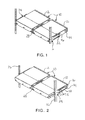
- FIG. 1 is a perspective view of an exemplary embodiment of a pair of patch panels of the present invention mounted on a rack illustrating both of the panels in a flush-mounted position;
- FIG. 2 is a perspective view of the exemplary embodiment of FIG. 1 illustrating both of the panels in an extended forward position;
- FIG. 3 is a perspective view of the exemplary embodiment of FIG. 1 illustrating one of the panels in an extended position and one of the panels in a flush-mounted position;
- FIG. 4 is a perspective view of an exemplary embodiment of the present invention illustrating the patch panel mounted to a wall.
- Exemplary embodiments of the present invention overcome the above disadvantages and other disadvantages not described above. Also, the present invention is not required to overcome the disadvantages described above, and an exemplary embodiment of the present invention may not overcome any of the problems described above.
- FIGS. 1-4 illustrate exemplary embodiments of the patch panel of the present invention.
- the patch panel can be used in wall mounting applications, rack mounting applications, and outside plant closure applications, without the need for modification, solving inventory problems.
- a fiber optics patch panel 10 includes a housing 12 that has a base 14 , and a pair of opposing first sides 16 extending perpendicularly from the base 14 .
- One or more bulkheads may be housed within the housing 12 for connecting bundles of optical wires (not shown), and the like.
- the panel 10 may also include a pair of opposing second sides 18 extending perpendicularly from the base 14 and perpendicular to the first sides 16 .
- the base 14 includes a plurality of wall mounting portions 20 for mounting the panel 10 to a wall, or the like.
- the embodiment of FIG. 4 illustrates an exemplary embodiment wherein the four wall mounting portions 20 are tear-drop shaped through holes that are flush with the base 14 and are in spaced arrangement relative to one another.
- the through holes in the base 14 of the panel 10 allow the panel 10 to be attached directly to a wall without the need for additional mounting brackets or any further modifications.
- the base 14 is located at an underside of each of the panels 10 and thus, the wall mounting portion 20 , although included, is not shown.
- the wall mounting portion 20 is not limited to the through holes illustrated in the exemplary embodiment of FIG. 4 .
- the wall mounting portion 20 may instead include one or more embossed or debossed portions (not shown) that each include a slot or through hole.
- an embossed portion i.e., a portion of the base that is raised in a direction away from the wall, may include a through hole at a top thereof for receiving a mount on a wall, or a debossed portion, i.e., a portion of the base that is indented in a direction toward the wall, may include a through hole at a bottom portion thereof for receiving the mount on the wall.
- Another alternative for the mounting portion 20 may be one or more snap connecting portions (not shown) that are configured to snap into and out of a plate disposed on the wall, or other such wall mount.
- Each of the first sides 16 includes a mounting portion 22 .
- the mounting portion 22 is a plurality of elongated through holes extending through each first side 16 .
- the panel 10 includes a rack attachment bracket 24 detachably attached to the mounting portion 22 of one of the first sides 16 of each panel 10 to mount the panel 10 to a rack 26 .
- a panel attachment 28 may be detachably attached to the mounting portion 22 of the other of the first sides 16 to mount the panel 10 to a second panel 10 . That is, the mounting portion 22 attaches the panel 10 either to another panel 10 or to a rack 26 .
- the panel attachment 28 may be one of many commonly-known fasteners.
- the panel attachment 28 is a plurality of bolts that extend through the holes on each side 16 , and corresponding nuts.
- those skilled in the art would understand many other arrangements for the mounting portion 22 and the panel attachment 28 that would detachably attach two panels 10 to one another, such as a screw, a clevis pin, etc.
- the rack attachment bracket 24 is a plate that includes at least one slot 30
- the mounting portion 22 on each first side may be a through hole in combination with a projection extending through the through hole that engages and slides within the slot 30 of the rack attachment bracket 24 .
- the rack attachment 24 may include a projection and the first side may include a slot as the mounting portion 22 .
- the mounting portion 22 may be a projection extending directly from a surface of the first side 16 .
- the width of the base 14 is one-half of the width of a standard rack mounting assembly in a 19 inch rack.
- Two panels 10 are attached to one another side by side through a panel attachment 28 whereby the two attached panels 10 fit into a single rack width.
- the exemplary embodiments of the panel 10 may be wall-mounted, as shown in FIG. 4 , in which case the base 14 of the panel 10 is positioned vertically, or instead can be rack-mounted, as shown in FIGS. 1-3 , in which case the base 14 is positioned horizontally.
- the panel 10 may also be mounted in many outdoor custom racks, which are typically half the width of an industry standard rack; that is, only a single panel 10 may be used to mount the panel 10 to a custom half-sized rack.
- the patch panel 10 When rack-mounted, the patch panel 10 is capable of transitioning from a “flush-mounted” position (shown in FIG. 1 ) to an extended position (shown in FIG. 3 ) by sliding relative to the rack 26 on which the panel 10 is mounted. Sliding the panel 10 to the extended position allows the bulkhead to be positioned within reach from a front of the rack 26 when another panel 10 is positioned directly above and in the flush-mounted position.
- the mounting portion 22 is one or more elongated through holes and the panel attachment 28 is a bolt and nut, or clevis pin, whereby the panel attachment 28 slides within the mounting portion 22 so that the panels 10 are slidable relative to one another.
- Each of the first sides 16 may include a wire insertion portion 32 for extending optical wires or bundles of wires therethrough.
- the wire insertion portion 32 is a U-shaped slot.
Abstract
Description
Claims (8)
Priority Applications (1)
| Application Number | Priority Date | Filing Date | Title |
|---|---|---|---|
| US12/810,472 US8687933B2 (en) | 2009-01-08 | 2010-01-05 | Field terminated fiber patch panel for rack and wall mounting |
Applications Claiming Priority (3)
| Application Number | Priority Date | Filing Date | Title |
|---|---|---|---|
| US14321409P | 2009-01-08 | 2009-01-08 | |
| US12/810,472 US8687933B2 (en) | 2009-01-08 | 2010-01-05 | Field terminated fiber patch panel for rack and wall mounting |
| PCT/US2010/020075 WO2010080745A1 (en) | 2009-01-08 | 2010-01-05 | Field terminated fiber patch panel for rack and wall mounting |
Publications (2)
| Publication Number | Publication Date |
|---|---|
| US20110044598A1 US20110044598A1 (en) | 2011-02-24 |
| US8687933B2 true US8687933B2 (en) | 2014-04-01 |
Family
ID=42316773
Family Applications (1)
| Application Number | Title | Priority Date | Filing Date |
|---|---|---|---|
| US12/810,472 Active 2030-02-14 US8687933B2 (en) | 2009-01-08 | 2010-01-05 | Field terminated fiber patch panel for rack and wall mounting |
Country Status (4)
| Country | Link |
|---|---|
| US (1) | US8687933B2 (en) |
| CA (1) | CA2743712C (en) |
| MX (1) | MX2011004760A (en) |
| WO (1) | WO2010080745A1 (en) |
Cited By (2)
| Publication number | Priority date | Publication date | Assignee | Title |
|---|---|---|---|---|
| US10261279B1 (en) * | 2017-10-12 | 2019-04-16 | Sumitomo Electric Lightwave Corp. | System and method for distributing high fiber count optical cable to network racks |
| US10345538B2 (en) | 2017-06-28 | 2019-07-09 | Sumitomo Electric Lightwave Corp. | System and method for joining and distributing a single optical fiber cable to multiple rack shelves |
Families Citing this family (30)
| Publication number | Priority date | Publication date | Assignee | Title |
|---|---|---|---|---|
| US8452148B2 (en) | 2008-08-29 | 2013-05-28 | Corning Cable Systems Llc | Independently translatable modules and fiber optic equipment trays in fiber optic equipment |
| US11294136B2 (en) | 2008-08-29 | 2022-04-05 | Corning Optical Communications LLC | High density and bandwidth fiber optic apparatuses and related equipment and methods |
| ATE534049T1 (en) | 2009-02-24 | 2011-12-15 | Ccs Technology Inc | CABLE HOLDING DEVICE OR ARRANGEMENT FOR USE WITH A CABLE |
| US8699838B2 (en) | 2009-05-14 | 2014-04-15 | Ccs Technology, Inc. | Fiber optic furcation module |
| US9075216B2 (en) | 2009-05-21 | 2015-07-07 | Corning Cable Systems Llc | Fiber optic housings configured to accommodate fiber optic modules/cassettes and fiber optic panels, and related components and methods |
| US8712206B2 (en) | 2009-06-19 | 2014-04-29 | Corning Cable Systems Llc | High-density fiber optic modules and module housings and related equipment |
| EP3693778A1 (en) | 2009-06-19 | 2020-08-12 | Corning Optical Communications LLC | High density and bandwidth fiber optic apparatuses and related equipment and methods |
| US8593828B2 (en) | 2010-02-04 | 2013-11-26 | Corning Cable Systems Llc | Communications equipment housings, assemblies, and related alignment features and methods |
| US8913866B2 (en) | 2010-03-26 | 2014-12-16 | Corning Cable Systems Llc | Movable adapter panel |
| CA2796221C (en) | 2010-04-16 | 2018-02-13 | Ccs Technology, Inc. | Sealing and strain relief device for data cables |
| US9720195B2 (en) | 2010-04-30 | 2017-08-01 | Corning Optical Communications LLC | Apparatuses and related components and methods for attachment and release of fiber optic housings to and from an equipment rack |
| US9075217B2 (en) | 2010-04-30 | 2015-07-07 | Corning Cable Systems Llc | Apparatuses and related components and methods for expanding capacity of fiber optic housings |
| US8879881B2 (en) | 2010-04-30 | 2014-11-04 | Corning Cable Systems Llc | Rotatable routing guide and assembly |
| US9519118B2 (en) | 2010-04-30 | 2016-12-13 | Corning Optical Communications LLC | Removable fiber management sections for fiber optic housings, and related components and methods |
| US9279951B2 (en) | 2010-10-27 | 2016-03-08 | Corning Cable Systems Llc | Fiber optic module for limited space applications having a partially sealed module sub-assembly |
| CN203759315U (en) | 2010-11-30 | 2014-08-06 | 康宁光缆系统有限责任公司 | Optical fiber device |
| EP2671109A2 (en) | 2011-02-02 | 2013-12-11 | Corning Cable Systems LLC | Dense fiber optic connector assemblies and related connectors and cables suitable for establishing optical connections for optical backplanes in equipment racks |
| US9008485B2 (en) | 2011-05-09 | 2015-04-14 | Corning Cable Systems Llc | Attachment mechanisms employed to attach a rear housing section to a fiber optic housing, and related assemblies and methods |
| US8391663B2 (en) | 2011-05-24 | 2013-03-05 | Methode Electronics, Inc. | Rack cabling system |
| CN103649805B (en) | 2011-06-30 | 2017-03-15 | 康宁光电通信有限责任公司 | Fiber plant assembly of shell using non-U-width size and associated method |
| US8953924B2 (en) | 2011-09-02 | 2015-02-10 | Corning Cable Systems Llc | Removable strain relief brackets for securing fiber optic cables and/or optical fibers to fiber optic equipment, and related assemblies and methods |
| US9038832B2 (en) | 2011-11-30 | 2015-05-26 | Corning Cable Systems Llc | Adapter panel support assembly |
| EP2627102A1 (en) | 2012-02-07 | 2013-08-14 | 3M Innovative Properties Company | Rack-mountable telecommunications patch panel |
| US9250409B2 (en) | 2012-07-02 | 2016-02-02 | Corning Cable Systems Llc | Fiber-optic-module trays and drawers for fiber-optic equipment |
| US9042702B2 (en) | 2012-09-18 | 2015-05-26 | Corning Cable Systems Llc | Platforms and systems for fiber optic cable attachment |
| ES2551077T3 (en) | 2012-10-26 | 2015-11-16 | Ccs Technology, Inc. | Fiber optic management unit and fiber optic distribution device |
| US8985862B2 (en) | 2013-02-28 | 2015-03-24 | Corning Cable Systems Llc | High-density multi-fiber adapter housings |
| CN104614822A (en) * | 2013-11-05 | 2015-05-13 | 深圳市华为安捷信电气有限公司 | Jumper fiber device, port panel and jumper fiber system |
| EP2998773A1 (en) * | 2014-09-19 | 2016-03-23 | CCS Technology, Inc. | Mounting bracket and fiber optic distribution device |
| US9720196B2 (en) * | 2015-02-10 | 2017-08-01 | Commscope, Inc. Of North Carolina | Bridging connector for adjacent sliding trays |
Citations (15)
| Publication number | Priority date | Publication date | Assignee | Title |
|---|---|---|---|---|
| US5142606A (en) * | 1990-01-22 | 1992-08-25 | Porta Systems Corp. | Optical fiber cable distribution frame and support |
| US5145197A (en) * | 1987-09-14 | 1992-09-08 | Contemporary Medical Equipment Corp. | Folding wheelchair with rigid seat |
| US5497444A (en) * | 1994-01-21 | 1996-03-05 | Adc Telecommunications, Inc. | High-density fiber distribution frame |
| US6301424B1 (en) * | 2000-04-13 | 2001-10-09 | Lucent Technologies Inc. | Distribution frame cable routing apparatus |
| US20030223723A1 (en) * | 2002-05-28 | 2003-12-04 | Massey Gaines N. | Reconfigurable fiber optic cable management enclosure |
| US6785459B2 (en) | 2001-06-26 | 2004-08-31 | Adc Telecommunications, Inc. | Cable management brackets and cabinet |
| US20060018622A1 (en) * | 2004-07-22 | 2006-01-26 | Caveney Jack E | Front access punch down patch panel |
| US20060025010A1 (en) | 2004-07-28 | 2006-02-02 | Spitaels James S | Multi-port cabling system and method |
| US7087840B2 (en) | 2004-12-03 | 2006-08-08 | Hubbell Incorporated | Cable management system with patch panel |
| US20070227992A1 (en) * | 2002-07-18 | 2007-10-04 | Innovation First, Inc., A Texas Corporation | Sliding Rack-Mountable Shelf for Rack-Mountable Components |
| US20080085094A1 (en) * | 2006-10-10 | 2008-04-10 | Dennis Krampotich | Cable management drawer with access panel |
| US20080247723A1 (en) * | 2005-08-02 | 2008-10-09 | Adc Telecommunications, Inc. | Cable management panel with rear entry |
| US20080311786A1 (en) * | 2005-01-21 | 2008-12-18 | Leviton Manufacturing Co., Inc. | Cable slack manager system and method |
| US20090067800A1 (en) * | 2007-09-07 | 2009-03-12 | Mariano Perez Vazquez | Fiber optic adapter module and tray |
| US8452148B2 (en) * | 2008-08-29 | 2013-05-28 | Corning Cable Systems Llc | Independently translatable modules and fiber optic equipment trays in fiber optic equipment |
-
2010
- 2010-01-05 MX MX2011004760A patent/MX2011004760A/en active IP Right Grant
- 2010-01-05 US US12/810,472 patent/US8687933B2/en active Active
- 2010-01-05 CA CA2743712A patent/CA2743712C/en not_active Expired - Fee Related
- 2010-01-05 WO PCT/US2010/020075 patent/WO2010080745A1/en active Application Filing
Patent Citations (15)
| Publication number | Priority date | Publication date | Assignee | Title |
|---|---|---|---|---|
| US5145197A (en) * | 1987-09-14 | 1992-09-08 | Contemporary Medical Equipment Corp. | Folding wheelchair with rigid seat |
| US5142606A (en) * | 1990-01-22 | 1992-08-25 | Porta Systems Corp. | Optical fiber cable distribution frame and support |
| US5497444A (en) * | 1994-01-21 | 1996-03-05 | Adc Telecommunications, Inc. | High-density fiber distribution frame |
| US6301424B1 (en) * | 2000-04-13 | 2001-10-09 | Lucent Technologies Inc. | Distribution frame cable routing apparatus |
| US6785459B2 (en) | 2001-06-26 | 2004-08-31 | Adc Telecommunications, Inc. | Cable management brackets and cabinet |
| US20030223723A1 (en) * | 2002-05-28 | 2003-12-04 | Massey Gaines N. | Reconfigurable fiber optic cable management enclosure |
| US20070227992A1 (en) * | 2002-07-18 | 2007-10-04 | Innovation First, Inc., A Texas Corporation | Sliding Rack-Mountable Shelf for Rack-Mountable Components |
| US20060018622A1 (en) * | 2004-07-22 | 2006-01-26 | Caveney Jack E | Front access punch down patch panel |
| US20060025010A1 (en) | 2004-07-28 | 2006-02-02 | Spitaels James S | Multi-port cabling system and method |
| US7087840B2 (en) | 2004-12-03 | 2006-08-08 | Hubbell Incorporated | Cable management system with patch panel |
| US20080311786A1 (en) * | 2005-01-21 | 2008-12-18 | Leviton Manufacturing Co., Inc. | Cable slack manager system and method |
| US20080247723A1 (en) * | 2005-08-02 | 2008-10-09 | Adc Telecommunications, Inc. | Cable management panel with rear entry |
| US20080085094A1 (en) * | 2006-10-10 | 2008-04-10 | Dennis Krampotich | Cable management drawer with access panel |
| US20090067800A1 (en) * | 2007-09-07 | 2009-03-12 | Mariano Perez Vazquez | Fiber optic adapter module and tray |
| US8452148B2 (en) * | 2008-08-29 | 2013-05-28 | Corning Cable Systems Llc | Independently translatable modules and fiber optic equipment trays in fiber optic equipment |
Cited By (4)
| Publication number | Priority date | Publication date | Assignee | Title |
|---|---|---|---|---|
| US10345538B2 (en) | 2017-06-28 | 2019-07-09 | Sumitomo Electric Lightwave Corp. | System and method for joining and distributing a single optical fiber cable to multiple rack shelves |
| US10261279B1 (en) * | 2017-10-12 | 2019-04-16 | Sumitomo Electric Lightwave Corp. | System and method for distributing high fiber count optical cable to network racks |
| US20190113704A1 (en) * | 2017-10-12 | 2019-04-18 | Sumitomo Electric Lightwave Corp. | System and method for distributing high fiber count optical cable to network racks |
| WO2019074697A1 (en) * | 2017-10-12 | 2019-04-18 | Sumitomo Electric Lightwave Corp. | System and method for distributing high fiber count optical cable to network racks |
Also Published As
| Publication number | Publication date |
|---|---|
| CA2743712C (en) | 2017-01-03 |
| WO2010080745A1 (en) | 2010-07-15 |
| MX2011004760A (en) | 2011-06-01 |
| US20110044598A1 (en) | 2011-02-24 |
| CA2743712A1 (en) | 2010-07-15 |
Similar Documents
| Publication | Publication Date | Title |
|---|---|---|
| US8687933B2 (en) | Field terminated fiber patch panel for rack and wall mounting | |
| US7916502B2 (en) | Stackable cable tray | |
| US9782018B2 (en) | Modular wall assembly for a cosmetic fixture system | |
| US7351116B2 (en) | Connecting element | |
| EP2528349B1 (en) | Bracket to be used in a vertical cable manager | |
| US20070196071A1 (en) | Patch panel | |
| US8424827B2 (en) | Cable and box support plate | |
| US20100068923A1 (en) | Side mounted patch panel | |
| CA2404844A1 (en) | Rf circuit modules and integrated chassis with power interface for rf circuit modules | |
| US8221169B2 (en) | Fanning module, fanning strip, and cable management panel | |
| US20090090534A1 (en) | Cable management patch panel system with vertical ducting | |
| US10263399B2 (en) | Multiple latching feet for electrical connector assembly | |
| US20100209063A1 (en) | Patch panel system | |
| US11512824B2 (en) | Panel light mounting structure, a panel light and mounting method thereof | |
| MX2008005050A (en) | Equipment rack support bracket for power distribution units. | |
| US7154052B2 (en) | Device plate for mounting a communications device to a raceway | |
| KR20080031895A (en) | A communication apparatus rack mounting server and network apparatus compatibly | |
| US9516780B2 (en) | Device for accommodating mounting rail module cases | |
| US20090056969A1 (en) | Commercial plastic electrical boxes with metal sections | |
| US20040144737A1 (en) | Mounting tray for idc junction modules | |
| CN102544785A (en) | A device for positioning at least one multiple round plug | |
| US10772231B2 (en) | Patch panel including a device for attaching a plug-in module | |
| JP2017195167A (en) | Lighting fixture | |
| JP2010054894A (en) | Optical terminal box | |
| JP2011060988A (en) | Installation mechanism of patch panel |
Legal Events
| Date | Code | Title | Description |
|---|---|---|---|
| AS | Assignment |
Owner name: AFL TELECOMMUNICATIONS LLC, SOUTH CAROLINA Free format text: ASSIGNMENT OF ASSIGNORS INTEREST;ASSIGNORS:SRUTKOWSKI, LAWRENCE;LICHOULAS, TED;TURNER, CHUCK;REEL/FRAME:024592/0414 Effective date: 20100517 |
|
| STCF | Information on status: patent grant |
Free format text: PATENTED CASE |
|
| FEPP | Fee payment procedure |
Free format text: PAYOR NUMBER ASSIGNED (ORIGINAL EVENT CODE: ASPN); ENTITY STATUS OF PATENT OWNER: LARGE ENTITY |
|
| MAFP | Maintenance fee payment |
Free format text: PAYMENT OF MAINTENANCE FEE, 4TH YEAR, LARGE ENTITY (ORIGINAL EVENT CODE: M1551) Year of fee payment: 4 |
|
| MAFP | Maintenance fee payment |
Free format text: PAYMENT OF MAINTENANCE FEE, 8TH YEAR, LARGE ENTITY (ORIGINAL EVENT CODE: M1552); ENTITY STATUS OF PATENT OWNER: LARGE ENTITY Year of fee payment: 8 |