US8702316B2 - Magnetic connector with optical signal path - Google Patents
Magnetic connector with optical signal path Download PDFInfo
- Publication number
- US8702316B2 US8702316B2 US12/910,141 US91014110A US8702316B2 US 8702316 B2 US8702316 B2 US 8702316B2 US 91014110 A US91014110 A US 91014110A US 8702316 B2 US8702316 B2 US 8702316B2
- Authority
- US
- United States
- Prior art keywords
- power
- data
- connector
- power supply
- fiber
- Prior art date
- Legal status (The legal status is an assumption and is not a legal conclusion. Google has not performed a legal analysis and makes no representation as to the accuracy of the status listed.)
- Active, expires
Links
Images


Classifications
-
- H—ELECTRICITY
- H01—ELECTRIC ELEMENTS
- H01R—ELECTRICALLY-CONDUCTIVE CONNECTIONS; STRUCTURAL ASSOCIATIONS OF A PLURALITY OF MUTUALLY-INSULATED ELECTRICAL CONNECTING ELEMENTS; COUPLING DEVICES; CURRENT COLLECTORS
- H01R24/00—Two-part coupling devices, or either of their cooperating parts, characterised by their overall structure
-
- G—PHYSICS
- G02—OPTICS
- G02B—OPTICAL ELEMENTS, SYSTEMS OR APPARATUS
- G02B6/00—Light guides; Structural details of arrangements comprising light guides and other optical elements, e.g. couplings
- G02B6/24—Coupling light guides
- G02B6/36—Mechanical coupling means
- G02B6/38—Mechanical coupling means having fibre to fibre mating means
- G02B6/3807—Dismountable connectors, i.e. comprising plugs
- G02B6/381—Dismountable connectors, i.e. comprising plugs of the ferrule type, e.g. fibre ends embedded in ferrules, connecting a pair of fibres
- G02B6/3817—Dismountable connectors, i.e. comprising plugs of the ferrule type, e.g. fibre ends embedded in ferrules, connecting a pair of fibres containing optical and electrical conductors
-
- G—PHYSICS
- G02—OPTICS
- G02B—OPTICAL ELEMENTS, SYSTEMS OR APPARATUS
- G02B6/00—Light guides; Structural details of arrangements comprising light guides and other optical elements, e.g. couplings
- G02B6/24—Coupling light guides
- G02B6/36—Mechanical coupling means
- G02B6/38—Mechanical coupling means having fibre to fibre mating means
- G02B6/3807—Dismountable connectors, i.e. comprising plugs
- G02B6/3873—Connectors using guide surfaces for aligning ferrule ends, e.g. tubes, sleeves, V-grooves, rods, pins, balls
- G02B6/3886—Magnetic means to align ferrule ends
-
- G—PHYSICS
- G06—COMPUTING; CALCULATING OR COUNTING
- G06F—ELECTRIC DIGITAL DATA PROCESSING
- G06F1/00—Details not covered by groups G06F3/00 - G06F13/00 and G06F21/00
- G06F1/16—Constructional details or arrangements
-
- G—PHYSICS
- G06—COMPUTING; CALCULATING OR COUNTING
- G06F—ELECTRIC DIGITAL DATA PROCESSING
- G06F1/00—Details not covered by groups G06F3/00 - G06F13/00 and G06F21/00
- G06F1/16—Constructional details or arrangements
- G06F1/1601—Constructional details related to the housing of computer displays, e.g. of CRT monitors, of flat displays
-
- G—PHYSICS
- G06—COMPUTING; CALCULATING OR COUNTING
- G06F—ELECTRIC DIGITAL DATA PROCESSING
- G06F1/00—Details not covered by groups G06F3/00 - G06F13/00 and G06F21/00
- G06F1/26—Power supply means, e.g. regulation thereof
-
- H—ELECTRICITY
- H01—ELECTRIC ELEMENTS
- H01R—ELECTRICALLY-CONDUCTIVE CONNECTIONS; STRUCTURAL ASSOCIATIONS OF A PLURALITY OF MUTUALLY-INSULATED ELECTRICAL CONNECTING ELEMENTS; COUPLING DEVICES; CURRENT COLLECTORS
- H01R13/00—Details of coupling devices of the kinds covered by groups H01R12/70 or H01R24/00 - H01R33/00
- H01R13/66—Structural association with built-in electrical component
- H01R13/665—Structural association with built-in electrical component with built-in electronic circuit
- H01R13/6675—Structural association with built-in electrical component with built-in electronic circuit with built-in power supply
-
- H—ELECTRICITY
- H01—ELECTRIC ELEMENTS
- H01R—ELECTRICALLY-CONDUCTIVE CONNECTIONS; STRUCTURAL ASSOCIATIONS OF A PLURALITY OF MUTUALLY-INSULATED ELECTRICAL CONNECTING ELEMENTS; COUPLING DEVICES; CURRENT COLLECTORS
- H01R13/00—Details of coupling devices of the kinds covered by groups H01R12/70 or H01R24/00 - H01R33/00
- H01R13/62—Means for facilitating engagement or disengagement of coupling parts or for holding them in engagement
- H01R13/6205—Two-part coupling devices held in engagement by a magnet
-
- H—ELECTRICITY
- H01—ELECTRIC ELEMENTS
- H01R—ELECTRICALLY-CONDUCTIVE CONNECTIONS; STRUCTURAL ASSOCIATIONS OF A PLURALITY OF MUTUALLY-INSULATED ELECTRICAL CONNECTING ELEMENTS; COUPLING DEVICES; CURRENT COLLECTORS
- H01R13/00—Details of coupling devices of the kinds covered by groups H01R12/70 or H01R24/00 - H01R33/00
- H01R13/66—Structural association with built-in electrical component
- H01R13/6608—Structural association with built-in electrical component with built-in single component
- H01R13/6616—Structural association with built-in electrical component with built-in single component with resistor
-
- H—ELECTRICITY
- H01—ELECTRIC ELEMENTS
- H01R—ELECTRICALLY-CONDUCTIVE CONNECTIONS; STRUCTURAL ASSOCIATIONS OF A PLURALITY OF MUTUALLY-INSULATED ELECTRICAL CONNECTING ELEMENTS; COUPLING DEVICES; CURRENT COLLECTORS
- H01R27/00—Coupling parts adapted for co-operation with two or more dissimilar counterparts
- H01R27/02—Coupling parts adapted for co-operation with two or more dissimilar counterparts for simultaneous co-operation with two or more dissimilar counterparts
Definitions
- Mobile computing devices have become very popular the past several years. Users have chosen these devices not only for their portability, they have chosen them to be replacements for their traditional computers as well. These mobile devices thus fill two niches, as on-the-go computing and as desktop replacements. As a desktop replacement, there are two needs that these portable computers must satisfy.
- the first of these needs is the ability to function the length of a workday. Unfortunately, this exceeds current battery capacity; thus the laptop needs to be plugged in to a power source for at least a portion of the day.
- the second need to be satisfied is the ability to transfer data over a physical connection.
- circuits, apparatus, and methods that provide a power and data transfer system that can supply both power and data to a laptop or other mobile computing device using a single connection.
- a power and data adapter that can provide power and data to the mobile computing device using a single cable.
- a connector system that can connect this single cable to the mobile computing device. To avoid the consequence of laptops being pulled to the ground when a cable is tripped over, it is desirable that the connector system easily disengages when the cable is pulled away from the mobile computing device.
- embodiments of the present invention provide circuits, apparatus, and methods for power and data transfer systems that can supply both power and data to mobile computing or other types of devices using a single connection. Further embodiments of the present invention also provide power and data adapters that can provide data and power to mobile computing or other types of devices using a single cable. Further embodiments of the present invention provide connector systems for connecting fiber-optic and power cables to mobile computing or other types of devices. Further embodiments of the present invention provide connector systems with connector inserts that easily disengage from connector receptacles.
- An exemplary embodiment of the present invention provides a connector system that provides both power and data.
- data is provided using fiber-optic connections. These connections may include one, two, four, or other numbers of fiber-optic cables.
- four fiber-optic cables are used, where two cables are used for data transmission and two are used for data reception.
- the four fiber-optic cables are arranged such that the connection between a connector insert and a connector receptacle can be made in two ways along one axis of symmetry. That is, the connector insert can be inserted into the connector receptacle either right side up, or upside down, and the data connection is made using the four fiber-optic cables.
- This exemplary embodiment of the present invention also employs two, four, or more contacts for power transmission.
- a specific embodiment of the present invention provides four such contacts, two for a power supply voltage and two for ground connections. This allows relatively high currents to be provided to the mobile device, enabling rapid battery recharging.
- the connector insert includes four magnets arranged with alternating polarities. Magnetic field lines originating in a first magnet in the connector insert travel through an attractor plate in the receptacle and terminate in a second magnet in the insert, where the first and second magnets have opposite polarities.
- this power and data adapter may receive power from a wall, car, or other type outlet.
- the power and data adapter may directly connect to the outlet, or it may connect to the outlet via a power cord or cable.
- a specific embodiment of the present invention plugs directly into a wall outlet.
- the power and data adapter may also include circuitry for converting AC power to DC power suitable for being provided to the mobile computing or other type of device.
- the power and data adapter may translate data between the mobile computing or other type of device and one or more other devices. These one or more other devices may communicate using one or more protocols. The power and data adapter may thus translate or convert data using these one or more protocols to optical data to be provided to the mobile computing or other type of device. The power and data adapter may also translate or convert optical data from the computing or other type of device to data consistent with one or more of these protocols to be provided to one or more other devices. The data may be provided by the power and data adapter to the connector system and received by the power and data adapter from the connector system using one or more fiber-optic cables.
- the power and data adapter may provide and receive data to and from other devices using fiber-optic cables, or other types of wired or wireless connections such as Local Area Networking (LAN), Universal Serial Bus (USB), Digital Visual Interface (DVI), DisplayPort, IEEE 802.11 a, b, g, or other types of connections.
- LAN Local Area Networking
- USB Universal Serial Bus
- DVI Digital Visual Interface
- DisplayPort IEEE 802.11 a, b, g, or other types of connections.
- USB devices may communicate with each other through the power and data adapter.
- the power and data adapter may also include circuitry for translating among these wired and wireless protocols and one or more protocols suitable for fiber-optic communications.
- the power and data adapter may communicate with the mobile computing or other type of device over a single cable that includes conductors for the DC power and one or more fiber-optic cables.
- Another exemplary embodiment of the present invention prevents power from being applied at a connector insert until the connector insert is placed in a connector receptacle.
- the power and data adapter provides a small amount of current between power and ground pins of the connector insert. A resulting voltage is then sense. If the voltage is in a predetermined range, power is applied to the insert's power pins.
- an identification or other signal is provided by the connector insert. If a proper response is received, power is applied to the insert's power pins. Further embodiments may require that such an identification signal be periodically provided. When the identification is not received for a period of time, power is removed from the connector insert.
- FIG. 1 illustrates a power and data transfer system according to an embodiment of the present invention
- FIG. 3 illustrates another power and data transfer system according to an embodiment of the present invention
- FIG. 4 illustrates another power and data transfer system according to an embodiment of the present invention
- FIGS. 5A-5D illustrate front views of connector inserts and a connector receptacles according to embodiments of the present invention
- FIGS. 6A-6C illustrate transmit and receive circuitry employed by connector systems according to embodiments of the present invention
- FIG. 7 illustrates a top view of a connector insert and connector receptacle according to an embodiment of the present invention
- FIG. 8 illustrates a side view of a connector insert and connector receptacle according to an embodiment of the present invention
- FIG. 9 illustrates a side view of another connector insert and connector receptacle according to an embodiment of the present invention.
- FIG. 10 illustrates electrical pin and fiber-optical line positions of a connector insert according to embodiment of the present invention
- FIG. 11 illustrates a power and data transfer system according to an embodiment of the present invention
- FIG. 12 illustrates another power and data transfer system according to an embodiment of the present invention
- FIG. 13 illustrates a method of applying power to a connector according to an embodiment of the present invention
- FIG. 14 illustrates circuitry in a power and data adapter according to an embodiment of the present invention.
- FIGS. 15 and 16 illustrate the operation of the circuitry in FIG. 14 .
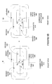
- FIG. 1 illustrates a power and data transfer system according to an embodiment of the present invention.
- This figure includes a power and data adapter 110 and a connector system including a connector receptacle 132 and a connector insert 120 coupled to the power and data adapter 110 via cable 124 .
- This figure as with the other included figures, is shown for illustrative purposes only and does not limit either the possible embodiments of the present invention or the claims.
- the power and data adapter 110 receives a first power supply voltage and provides either the first power supply voltage or a second power supply voltage to the connector insert 120 via the fiber-optic and DC power cable 124 .
- the power and data adapter 110 receives power at power terminals 112 .
- the power terminals 112 may be arranged to receive AC power from a conventional wall socket or other appropriate source. In other embodiments of the present invention, the power and data adapter 110 may receive power from a car outlet or other source.
- the power and data adapter 110 may receive and provide data using one or more data connections.
- the data connections include a USB 114 , Ethernet or RJ 45 115 , DVI connector 116 , and optical connection 118 .
- the optical connection can be an optical connection such as a Sony/Philips Digital Interconnect Format (S/PDIF), optical Ethernet, Fiber Optic Service (FIOS), 100 or 1000baseFL, or other fiber optic connection.
- S/PDIF Sony/Philips Digital Interconnect Format
- FIOS Fiber Optic Service
- 100 or 1000baseFL or other fiber optic connection.
- Data received at the data connections is converted to optical data by the power and data adapter 110 and provided to the connector insert 120 via the fiber-optic and DC power cable 124 .
- Data received at the connector insert 120 is received by the power and data adapter 110 , again via the fiber-optic and DC power cable 124 .
- the power and data adapter 110 can then convert this data and provide it on the appropriate connector.
- the power and data adapter 110 provides DC power and fiber-optic data to the connector insert 120 using the fiber-optic and DC power cable 124 .
- the fiber-optic and DC power cable 124 may be connected to the power and data adapter 110 using a connector system such as the connector insert 120 and connector receptacle 132 .
- the fiber-optic and DC power cable 124 can be hardwired to the power and data adapter 110 .
- the connector system includes the connector insert 120 and the connector receptacle 132 .
- the connector insert 120 further includes a connector insert or housing 122 , which may be held by a user when the connector insert 120 is inserted into the connector receptacle 132 .
- the connector receptacle 132 is located in a laptop 130 , though in other embodiments of the present invention, the connector receptacle 132 may be located in other types of mobile or other electronic devices.
- the connector receptacle 132 may be located in a portable media player, display, cell phone, desktop computer, or other mobile or non-mobile computing or other type of device.
- the power and data adapter 110 is capable of determining one or more characteristics of a computer, such as the laptop 130 that it is connected to. These characteristics can be determined by the power and data adapter sensing a voltage at the connector receptacle 132 , by reading data stored on the computer, by receiving data from the computer, or in other ways. The characteristics can be power supply requirements, the type of data or format needed by the computer, or other characteristics. After determining these characteristics, the power and data adapter 110 then configures itself to provide the required power and data.
- a laptop 130 or other computer is capable of determining one or more characteristics of a power and data adapter, such as the power and data adapter 110 . These characteristics can be determined by the laptop sensing a voltage at the connector insert 120 , by reading data stored on the power and data adapter 110 , by receiving data from the power and data adapter 110 , or in other ways. The characteristics can be power supply capabilities, the type of data or format that can be provided by the power and data adapter 110 , or other characteristics. After determining these characteristics, the computer can configure itself to make use of the available power and data.
- FIG. 2 illustrates circuitry for a power and data adapter, such as the power and data adapter 110 in FIG. 1 or other power and data adapters consistent with embodiments of the present invention.
- a transformer and rectifier 210 receive power from power connection 220 .
- the power connection 220 may be power prongs configured to be inserted into a conventional wall socket or outlet.
- the AC power received at the power connection 220 is converted by the transformer and rectifier 210 and provided to a DC power supply circuit 215 , which generates regulated DC power supplies that can be provided to a connector insert and to the remaining power and data adapter circuitry.
- This example further includes a number of data ports, including USB data ports 230 and 232 , local area network port 240 , DVI port 250 , and optical port 255 .
- fewer, more, and other types of data ports may be included. These ports may be wired electronic data ports, fiber-optic data ports, wireless data ports, or other types of data ports. Data may be received and transmitted at one or more of these ports. Data received at these ports may be translated by translation circuitry 270 into fiber-optic data and provided by the fiber-optic interface 260 to the connector insert. Similarly, data received from the connector insert by the fiber-optic interface 260 can be translated by the translation circuitry 270 and provided to the appropriate data port.
- USB data ports 230 and 232 may communicate with each other via hub 234 .
- the power and data adapter 110 acts as a USB hub, where data can be transferred from one USB port to another or from one USB port to a connector insert via fiber-optic interface 260 and translation circuitry 270 .
- the power and data adapter may have its own power cable. This allows the power and data adapter to be remotely located from its power source. An example is shown in the following figure.
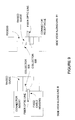
- FIG. 3 illustrates another power and data transfer system according to an embodiment of the present invention.
- This example includes a power and data adapter 310 and a connector system including a connector insert 320 and connector receptacle 332 , where the connector insert 320 and power and data adapter 310 are coupled via DC power and fiber-optic cable 324 .
- a power cable 350 powers the power and data adapter 310 .
- the power cable 350 includes a power connection 352 , which may include prongs adapted to be inserted into a wall socket.
- a power transformer 354 may convert AC power received at the power connection 352 to DC power for use by the power and data adapter 310 .
- the DC power provided by the power transformer 354 may also be provided to the connector insert 320 , though in other embodiments of the present invention, a DC-to-DC converter is used to provide a second DC voltage to the connector insert 320 .
- the DC power be provided to a connector insert separately from the fiber-optic data.
- An example is shown in the following figure.
- FIG. 4 illustrates another power and data transfer system according to an embodiment of the present invention.
- This example includes a data adapter 410 and a connector system including a connector insert 420 and connector receptacle 432 , where the connector insert 420 and data adapter 410 are coupled together over a fiber-optic cable 424 .
- a separate DC power cable 450 provides DC power to the connector insert 420 .
- the DC power cable 450 has a power connection 450 , which may include prongs adapted to fit into a wall outlet.
- a power transformer 454 which converts AC power received at the power connection 452 to DC power, which can be provided to the connector insert 420 .
- FIGS. 5A-5D illustrate front views of a connector insert 510 and a connector receptacle 560 according to an embodiment of the present invention. While this connector insert 510 and connector receptacle 560 are well suited for use with a power and data adapter according to an embodiment of the present invention, they may be used in other situations not including such a power and data adapter.
- a single fiber-optic line 530 is used to transfer optical data from the connector insert 510 to the connector receptacle 560 .
- the connector insert 510 includes a number of pins 520 on each side of the fiber-optic line 530 . In other embodiments, pins 520 and one or more fiber-optic lines 530 may have various configurations.
- pins 520 are shown. Two of these pins may be used to provide a positive power supply, while two pins may be used for ground. In other embodiments of the present invention, other power supplies may be provided.
- the pins 520 and fiber-optic line 530 are located in a recess 535 , which is surrounded by a raised guide 550 .
- An insert housing 540 may be employed to protect the raised guide 550 .
- the connector insert 510 inserts into the connector receptacle 560 .
- the connector receptacle 560 includes a corresponding number of contacts 570 and a fiber-optic line 580 .
- the contacts 570 and fiber-optic line 580 may be on a raised guide 595 .
- a recess 590 may surround the raised guide 595 .
- the recess may be located in a housing 585 , which may be a separate entity or may be a portion of a device such as a laptop computer.
- the raised guide 550 fits into the recess 590 .
- the raised guide 595 fits into the recess 535 .
- This arrangement provides alignment between the connector insert 510 and connector receptacle 560 .
- the connector insert 510 is easily disengaged when a cable connected to the connector insert 510 pulled away from the connector receptacle 560 .
- the connector insert 510 and connector receptacle 560 are magnetically attracted to each other. This may be accomplished by placing one or more magnets in either the connector insert 510 or connector receptacle 560 . In various embodiments of the present invention, one or more magnets are located in the connector insert 510 . In a specific embodiment of the present invention, four magnets are placed in the connector insert. Specifically, the raised guide 550 comprises four magnets. These magnets may be generally located in each corner of the connector insert 510 . These magnets further may have alternating polarities. In this specific embodiment of the present invention, the connector receptacle 560 includes an attractor plate. Specifically, an attractor plate is located behind recess 590 .
- This attractor plate may be made using a magnet or ferromagnetic material. In this way, field lines originating in one magnet in the connector insert 510 travel through the attraction plate in the connector receptacle 560 to a second magnet having an opposite polarity in the connector insert 510 . This increases the magnetic attraction between the connector insert 510 and connector receptacle 560 . Further details, for example details pertaining to these magnets, attractor plates, and alignment and disengagement features can be found in U.S. Pat. No. 7,311,526, which is incorporated by reference.
- the connector insert 510 may be inserted into the connector receptacle 560 either right side up or upside down relative to horizontal line “A.”
- only one fiber-optic line is used.
- data communication is only one way. In such a situation, no more than one fiber-optic line is needed.
- bidirectional or full-duplex communication is desired. In these situations, either one fiber-optic line may be multiplexed between transmit and receive channels, or other fiber-optic lines may be included. An example is shown in the following figure.
- FIG. 5B illustrates front views of a connector insert and connector receptacle according to an embodiment of the present invention.
- the connector insert 510 in this example includes two fiber-optic lines 530 .
- one fiber-optic line is used for transmitting and a second is used for receiving. This allows full-duplex communication without having to multiplex signals.
- the connector insert 510 can only be placed in the connector receptacle 560 in the right side up orientation. If the connector insert 510 is inserted into the connector receptacle 560 in an upside down position, the fiber-optic transmit channel of the connector insert 510 will be in communication with the transmit channel of the connector receptacle 560 .
- the TX and RX fiber optic lines 530 or 560 can be multiplexed, that is, they can be reversed if an upside down insertion is detected.
- the multiplexing can take place in either the connector insert 510 or the connector receptacle 560 . This multiplexing may be performed optically or electrically.
- an embodiment of the present invention employs four fiber-optic cables. An example is shown in the following figure.
- FIG. 5C illustrates front views of a connector insert and a connector receptacle according to an embodiment of the present invention.
- the connector insert 510 in this example includes four fiber-optic lines 530 .
- two lines are used for transmitting and two are used for receiving.
- the two transmitting and two receiving fiber-optic lines may each be implemented as one split fiber-optic cable. That is, each may be implemented as one fiber-optic cable whose end is split. This allows full-duplex communication without having to multiplex transmit and receive signals. Since the four fiber-optic lines are rotationally symmetrical, the connector insert 510 may be inserted into the connector receptacle 560 in either the right-side up or upside down positions.
- FIG. 5D illustrates front views of a connector insert and a connector receptacle according to another embodiment of the present invention.
- the connector insert 510 in this example includes four fiber-optic lines 530 . As before, two lines are used for transmitting and two are used for receiving. An additional pin, which may be a signal or a power pin, is placed in the center of the four fiber optic lines. This allows backward compatibility with currently available connectors and receptacles that are discussed in U.S. Pat. No. 7,311,526, which is incorporated by reference. Again, since the four fiber-optic lines are rotationally symmetrical the connector insert 510 may be inserted into the connector receptacle 560 in either the right-side up or upside down positions.
- the additional pin show may be included in the other examples above, and in other connector systems according to embodiments of the present invention.
- FIGS. 6A-6C illustrate transmit and receive circuitry employed by connector systems according to embodiments of the present invention.
- FIG. 6A only one fiber-optic cable is used, such as in the example shown in FIG. 5A .
- data provided by transmitter 610 and received by receiver 620 is multiplexed over a fiber-optic multiplexer 630 . That is, when transmitter 610 transmits data, transmitter 610 provides data to the fiber-optic multiplexer 630 , which provides it over the fiber-optic line. Data received over the fiber-optic line is multiplexed by the fiber-optic multiplexer 630 and provided to the receiver 620 .
- FIG. 6B two fiber-optic cables are used, such as in the example of FIG.
- the transmitter 610 and receiver 620 each have their own fiber-optic cable, so no multiplexing is required.
- the transmitter 610 and receiver 620 each have two fiber-optic cables. Accordingly, a fiber-optic cable from the transmitter 610 is split. Similarly, the fiber-optic cable to the receiver 620 is split.
- FIG. 7 illustrates a top view of a connector insert 710 and connector receptacle 760 according to an embodiment of the present invention.
- Connector insert 710 includes a number of pins 720 and a fiber-optic line 730 .
- a raised guide 750 surrounds the pins 720 and fiber-optic line 730 .
- the raised guide 750 is arranged to fit into the recess 790 in the connector receptacle 760 .
- the raised guide 795 on the connector receptacle 760 fits in the recess 735 of the connector insert 710 .
- the pins 720 are arranged to contact the contacts 770 and make electrical connections.
- the pins 720 may be biased, for example by a spring.
- the fiber-optic line 730 comes in close proximity with the fiber-optic line 780 in the connector receptacle 760 in order to form a fiber-optic connection.
- the fiber-optic connection reliability is enhanced by the use of lenses 732 and 782 .
- lenses are not used, rather the close proximity of the fiber-optic lines is relied upon.
- a fiber-optic line in the connector insert transfers data with a fiber-optic line in the connector receptacle.
- Successful transfers of data rely on the fiber-optic lines being in close proximity. This transfer can be aided by the use of a lens as shown above.
- lenses may be used to focus light provided and received by the fiber-optic lines.
- other devices such as collectors may be used. These collectors may be rounded, flat, or other shaped mirrors or reflectors to gather light provided by a fiber-optic line. Examples of these techniques are shown in the following figures.
- FIGS. 8 and 9 illustrate side views of a connector insert and connector receptacle according to an embodiment of the present invention.
- lenses 832 and 882 are used to improve the fiber-optic signal between fiber-optic lines 830 and 880 . These lenses focus light emitted and received by their corresponding fiber-optic line for improved reception
- collectors 936 and 986 are used to gather light received by their corresponding fiber-optic line to improve the signal reliability between fiber-optic lines 930 and 980 .
- the connector insert and connector receptacle each have five locations, where four locations are electrical connections and one location is for an optical data connection.
- Another embodiment of the present invention other arrangements are possible. In some of these arrangements, two pins are used for power, while two are used for ground.
- Various arrangements that may be employed by an embodiment of the present invention are shown in the following figure.
- FIG. 10 illustrates electrical pin and fiber-optical line positions of a connector insert according to embodiment of the present invention.
- two pins are used for power, while two are used for ground.
- the central location is used for optical data. This allows a connector insert to be inserted in one of two ways along a central line of symmetry, as discussed above.
- two of the five locations may be used for optical data lines. In still other embodiments of the present invention, either more or fewer than five locations may be used.
- connector insert pins can be supplied with power when the connector insert is not inserted into a connector receptacle.
- inadvertent currents may flow between pins of the connector insert when the connector insert comes in contact with a conductor of some sort, such as a paper clip.
- a conductor of some sort such as a paper clip.
- Having power applied to the connector insert when the connector insert is not located in the connector receptacle is particularly undesirable when there are magnets located in the connector insert, since these magnets may attract conductive materials.
- embodiments of the present invention determine whether a connector insert is inserted into a connector receptacle before applying power to the connector insert. Examples of this are shown in the following figures.
- FIG. 11 illustrates a power and data transfer system according to an embodiment of the present invention.
- the power and data adapter 1110 in this example does not apply power to a connector insert until the connector insert is seated in a connector receptacle.
- a power connection is made to a wall outlet or sockets using power terminals 1112 .
- the power and data adapter 1110 determines that connector insert 1120 is not seated in the connector receptacle 1132 . Accordingly, the power and data adapter 1110 does not provide power to the connector insert 1120 .
- the connector insert 1120 is inserted into the connector receptacle 1132 .
- the power and data adapter 1110 determines that the connector insert 1120 is located in the connector receptacle 1132 .
- the power and data adapter 1110 then applies power to the connector insert 1120 .
- FIG. 12 illustrates another power and data transfer system according to an embodiment of the present invention.
- the power and data adapter 1210 in this system does not apply power to a connector insert until it is seated in a connector receptacle.
- the connector insert 1220 is inserted into the connector receptacle 1232 .
- a power connection for the power and data adapter 1210 is made to a wall socket, for example, using power terminals 1212 .
- the power and data adapter 1210 determines that the connector insert 1220 is inserted into the connector receptacle 1232 . Accordingly, the power and data adapter 1210 applies power to the connector insert 1220 .
- a flowchart outlining this is shown in the following figure.
- FIG. 13 illustrates a method of applying power to a connector according to an embodiment of the present invention.
- power is received from a wall socket.
- act 1320 it is determined whether a connector insert has been inserted into a connector receptacle. If it is not, power is not applied to the connector insert in act 1330 . If the power and data adapter determines that the connector insert has been inserted into a connector receptacle, power is applied to the connector insert in act 1340 .
- act 1350 it is determined whether the connector insert has been removed. If it has not been removed, power continues to be applied to the connector insert in act 1340 . If the connector insert has been removed, then power is not applied to the connector insert in act 1330 .
- a determination that the connector insert has been inserted into a connector receptacle may be made by providing a sense current between the power and ground pins of the connector insert. If a voltage in a specific range is measured, power can then be applied to the connector insert.
- the device attached to the connector receptacle can receive, provide, or trade identification information with a power and data adapter.
- Example circuitry that may be employed by a power and data adapter to accomplish this is shown in the following figure.
- FIG. 14 illustrates circuitry in a power and data adapter according to an embodiment of the present invention.
- the power and data adapter 1410 includes a power connection 1412 , that may be, for example, prongs that are arranged to be inserted into a wall outlet. The prongs may rotate between two positions: a first position extended from the power and data adapter such that they may be inserted into a wall outlet, and a second position where they are not extended to save space.
- the power and data adapter 1410 further includes a transformer and rectifier circuit 1420 to convert the AC power received to the power connection to DC power that is provided to the power switch 1430 .
- the power switch 1430 determines whether power should be applied to the power lines 1432 in the DC power and data cable 1440 .
- the low current output and voltage sense circuit 1450 provides a small current between power and ground pins of a connector insert (not shown.) If a resulting voltage in the proper range is detected, power switch 1430 applies power between the power line 1442 and ground line 1444 . Following that, device identification can be received, provided, or traded over the optical data lines 1446 using the device identification interface circuitry 1460 .
- FIGS. 15 and 16 illustrate the operation of the circuitry in FIG. 14 .
- power is received at a power connection from a wall socket or other source.
- a low current is provided at an insert in act 1520 .
- a low current may be provided between the power and ground pins of a connector insert.
- a resulting voltage is measure, and it is determined whether the resulting voltage is in a specific range. If it is not in the specific range, then power is not switched to the connector insert in act 1540 . If a correct voltage is sensed, full power may be switched to the connector insert in act 1550 .
- identification data may be sent by the power and data adapter.
- act 1630 it is determined whether proper identification data is returned. If it is not, power is removed from the connector insert in act 1640 . At this point, a low current is again provided in act 1520 . If a proper identification is received in act 1630 , then power is maintained in the connector insert in act 1650 . This identification data can be checked periodically in act 1660 . If the data is received, power is maintained in act 1650 . Once the data is no longer periodically received, the power is removed from the connector insert in act 1640 , and again a low current is provided in act 1520 .
Abstract
Circuits, apparatus, and methods that provide a connector system that can supply both power and data to a mobile computing or other type of device using a single connection. Further examples also provide a power and data adapter that can provide power and data to a mobile computing device using a single cable. Further examples provide an easy disengagement when a cable connected to the connector is pulled. One such example provides a magnetic connector that uncouples without binding when its cord is pulled. Another example prevents power from being provided at a connector insert until the connector insert is placed in a connector receptacle.
Description
This application is a division of and claims priority from U.S. patent application Ser. No. 12/241,036 filed Sep. 30, 2008, the disclosure of which is incorporated by reference herein in its entirety.
Mobile computing devices have become very popular the past several years. Users have chosen these devices not only for their portability, they have chosen them to be replacements for their traditional computers as well. These mobile devices thus fill two niches, as on-the-go computing and as desktop replacements. As a desktop replacement, there are two needs that these portable computers must satisfy.
The first of these needs is the ability to function the length of a workday. Unfortunately, this exceeds current battery capacity; thus the laptop needs to be plugged in to a power source for at least a portion of the day. The second need to be satisfied is the ability to transfer data over a physical connection.
Presently, satisfying these two needs requires at least two connections to the mobile device; one for power and one for data transmission. But including two (or more) connectors increases cost and consumes space, typically along the side of the mobile device. It also requires the user to make two separate connections, thus limiting the usefulness and desirability of the mobile computing format.
These two connections also require the use of two cables. This in turn clutters a user's workspace, further degrading the mobile computing experience. Another way that a user's experience can quickly become unpleasant is when the user trips or otherwise becomes entangled with one of these cables, thereby pulling the laptop to the ground.
Thus, what is needed are circuits, apparatus, and methods that provide a power and data transfer system that can supply both power and data to a laptop or other mobile computing device using a single connection. To reduce the clutter caused by multiple cables, it is further desirable to have a power and data adapter that can provide power and data to the mobile computing device using a single cable. It is also desirable to have a connector system that can connect this single cable to the mobile computing device. To avoid the consequence of laptops being pulled to the ground when a cable is tripped over, it is desirable that the connector system easily disengages when the cable is pulled away from the mobile computing device.
Accordingly, embodiments of the present invention provide circuits, apparatus, and methods for power and data transfer systems that can supply both power and data to mobile computing or other types of devices using a single connection. Further embodiments of the present invention also provide power and data adapters that can provide data and power to mobile computing or other types of devices using a single cable. Further embodiments of the present invention provide connector systems for connecting fiber-optic and power cables to mobile computing or other types of devices. Further embodiments of the present invention provide connector systems with connector inserts that easily disengage from connector receptacles.
An exemplary embodiment of the present invention provides a connector system that provides both power and data. In various embodiments of the present invention, data is provided using fiber-optic connections. These connections may include one, two, four, or other numbers of fiber-optic cables. In a specific embodiment of the present invention, four fiber-optic cables are used, where two cables are used for data transmission and two are used for data reception. In this specific embodiment of the present invention, the four fiber-optic cables are arranged such that the connection between a connector insert and a connector receptacle can be made in two ways along one axis of symmetry. That is, the connector insert can be inserted into the connector receptacle either right side up, or upside down, and the data connection is made using the four fiber-optic cables. This exemplary embodiment of the present invention also employs two, four, or more contacts for power transmission. A specific embodiment of the present invention provides four such contacts, two for a power supply voltage and two for ground connections. This allows relatively high currents to be provided to the mobile device, enabling rapid battery recharging.
Another exemplary embodiment of the present invention provides a connector system that employs one or more magnets to engage a connector insert with a connector receptacle. These one or more magnets are attracted to an attraction plate in the connector receptacle, where the attraction plate is formed using a magnet or a ferromagnetic material. In a specific embodiment of the present invention, the connector insert includes four magnets arranged with alternating polarities. Magnetic field lines originating in a first magnet in the connector insert travel through an attractor plate in the receptacle and terminate in a second magnet in the insert, where the first and second magnets have opposite polarities.
Another exemplary embodiment of the present invention provides a power and data adapter capable of providing power and data over a single cable to a mobile computing or other type of device. In various embodiments of the present invention, this power and data adapter may receive power from a wall, car, or other type outlet. The power and data adapter may directly connect to the outlet, or it may connect to the outlet via a power cord or cable. A specific embodiment of the present invention plugs directly into a wall outlet. In this case, the power and data adapter may also include circuitry for converting AC power to DC power suitable for being provided to the mobile computing or other type of device.
The power and data adapter may translate data between the mobile computing or other type of device and one or more other devices. These one or more other devices may communicate using one or more protocols. The power and data adapter may thus translate or convert data using these one or more protocols to optical data to be provided to the mobile computing or other type of device. The power and data adapter may also translate or convert optical data from the computing or other type of device to data consistent with one or more of these protocols to be provided to one or more other devices. The data may be provided by the power and data adapter to the connector system and received by the power and data adapter from the connector system using one or more fiber-optic cables. The power and data adapter may provide and receive data to and from other devices using fiber-optic cables, or other types of wired or wireless connections such as Local Area Networking (LAN), Universal Serial Bus (USB), Digital Visual Interface (DVI), DisplayPort, IEEE 802.11 a, b, g, or other types of connections.
Other devices may communicate with each other through the power and data adapter. For example, two or more USB devices may communicate with each other via a corresponding number of USB connectors on the power and data adapter. The power and data adapter may also include circuitry for translating among these wired and wireless protocols and one or more protocols suitable for fiber-optic communications. The power and data adapter may communicate with the mobile computing or other type of device over a single cable that includes conductors for the DC power and one or more fiber-optic cables.
Another exemplary embodiment of the present invention prevents power from being applied at a connector insert until the connector insert is placed in a connector receptacle. In one embodiment of the present invention, the power and data adapter provides a small amount of current between power and ground pins of the connector insert. A resulting voltage is then sense. If the voltage is in a predetermined range, power is applied to the insert's power pins. In another embodiment of the present invention, an identification or other signal is provided by the connector insert. If a proper response is received, power is applied to the insert's power pins. Further embodiments may require that such an identification signal be periodically provided. When the identification is not received for a period of time, power is removed from the connector insert.
Various embodiments of the present invention may incorporate one or more of these and the other features described herein. A better understanding of the nature and advantages of the present invention may be gained by reference to the following detailed description and the accompanying drawings.
The power and data adapter 110 receives a first power supply voltage and provides either the first power supply voltage or a second power supply voltage to the connector insert 120 via the fiber-optic and DC power cable 124. In this specific example, the power and data adapter 110 receives power at power terminals 112. The power terminals 112 may be arranged to receive AC power from a conventional wall socket or other appropriate source. In other embodiments of the present invention, the power and data adapter 110 may receive power from a car outlet or other source.
The power and data adapter 110 may receive and provide data using one or more data connections. In this specific example, the data connections include a USB 114, Ethernet or RJ 45 115, DVI connector 116, and optical connection 118. The optical connection can be an optical connection such as a Sony/Philips Digital Interconnect Format (S/PDIF), optical Ethernet, Fiber Optic Service (FIOS), 100 or 1000baseFL, or other fiber optic connection. Data received at the data connections is converted to optical data by the power and data adapter 110 and provided to the connector insert 120 via the fiber-optic and DC power cable 124. Data received at the connector insert 120 is received by the power and data adapter 110, again via the fiber-optic and DC power cable 124. The power and data adapter 110 can then convert this data and provide it on the appropriate connector.
The power and data adapter 110 provides DC power and fiber-optic data to the connector insert 120 using the fiber-optic and DC power cable 124. In various embodiments of the present invention, the fiber-optic and DC power cable 124 may be connected to the power and data adapter 110 using a connector system such as the connector insert 120 and connector receptacle 132. In other embodiments of the present invention, the fiber-optic and DC power cable 124 can be hardwired to the power and data adapter 110.
The connector system includes the connector insert 120 and the connector receptacle 132. The connector insert 120 further includes a connector insert or housing 122, which may be held by a user when the connector insert 120 is inserted into the connector receptacle 132. In this specific example, the connector receptacle 132 is located in a laptop 130, though in other embodiments of the present invention, the connector receptacle 132 may be located in other types of mobile or other electronic devices. For example, the connector receptacle 132 may be located in a portable media player, display, cell phone, desktop computer, or other mobile or non-mobile computing or other type of device.
In various embodiments of the present invention, the power and data adapter 110 is capable of determining one or more characteristics of a computer, such as the laptop 130 that it is connected to. These characteristics can be determined by the power and data adapter sensing a voltage at the connector receptacle 132, by reading data stored on the computer, by receiving data from the computer, or in other ways. The characteristics can be power supply requirements, the type of data or format needed by the computer, or other characteristics. After determining these characteristics, the power and data adapter 110 then configures itself to provide the required power and data.
In various embodiments of the present invention, a laptop 130 or other computer is capable of determining one or more characteristics of a power and data adapter, such as the power and data adapter 110. These characteristics can be determined by the laptop sensing a voltage at the connector insert 120, by reading data stored on the power and data adapter 110, by receiving data from the power and data adapter 110, or in other ways. The characteristics can be power supply capabilities, the type of data or format that can be provided by the power and data adapter 110, or other characteristics. After determining these characteristics, the computer can configure itself to make use of the available power and data.
This example further includes a number of data ports, including USB data ports 230 and 232, local area network port 240, DVI port 250, and optical port 255. In various embodiments of the present invention, fewer, more, and other types of data ports may be included. These ports may be wired electronic data ports, fiber-optic data ports, wireless data ports, or other types of data ports. Data may be received and transmitted at one or more of these ports. Data received at these ports may be translated by translation circuitry 270 into fiber-optic data and provided by the fiber-optic interface 260 to the connector insert. Similarly, data received from the connector insert by the fiber-optic interface 260 can be translated by the translation circuitry 270 and provided to the appropriate data port. In various embodiments of the present invention, one or more of these data ports may communicate with each other. For example, USB data ports 230 and 232 may communicate with each other via hub 234. In this way, the power and data adapter 110 acts as a USB hub, where data can be transferred from one USB port to another or from one USB port to a connector insert via fiber-optic interface 260 and translation circuitry 270.
In various embodiments of the present invention, it is desirable if the power and data adapter does not need to be plugged directly into a wall outlet or other power supply source. In such an example, the power and data adapter may have its own power cable. This allows the power and data adapter to be remotely located from its power source. An example is shown in the following figure.
In this example, a power cable 350 powers the power and data adapter 310. The power cable 350 includes a power connection 352, which may include prongs adapted to be inserted into a wall socket. A power transformer 354 may convert AC power received at the power connection 352 to DC power for use by the power and data adapter 310. The DC power provided by the power transformer 354 may also be provided to the connector insert 320, though in other embodiments of the present invention, a DC-to-DC converter is used to provide a second DC voltage to the connector insert 320.
In other embodiments of the present invention, it is desirable that the DC power be provided to a connector insert separately from the fiber-optic data. An example is shown in the following figure.
Connector systems according to embodiments of the present invention include a connector insert and a connector receptacle that are capable of transferring a power supply, for example, a power supply including a supply voltage and a ground, and a fiber-optic data signal. Various embodiments of the present invention are arranged such that the connector insert is magnetically held in contact with the connector receptacle. These embodiments of the present invention provide a connector insert that is easily disengaged from its receptacle when a cable connected to the connector insert is pulled. Raised guides and corresponding recesses on the insert and receptacle can be used to align the connector insert to the connector receptacle. Examples are shown in the following figures.
The connector insert 510 inserts into the connector receptacle 560. The connector receptacle 560 includes a corresponding number of contacts 570 and a fiber-optic line 580. The contacts 570 and fiber-optic line 580 may be on a raised guide 595. A recess 590 may surround the raised guide 595. The recess may be located in a housing 585, which may be a separate entity or may be a portion of a device such as a laptop computer.
When the connector insert 510 is mated with the connector receptacle 560, the raised guide 550 fits into the recess 590. Similarly, the raised guide 595 fits into the recess 535. This arrangement provides alignment between the connector insert 510 and connector receptacle 560. Also, the connector insert 510 is easily disengaged when a cable connected to the connector insert 510 pulled away from the connector receptacle 560.
In various embodiments of the present invention, the connector insert 510 and connector receptacle 560 are magnetically attracted to each other. This may be accomplished by placing one or more magnets in either the connector insert 510 or connector receptacle 560. In various embodiments of the present invention, one or more magnets are located in the connector insert 510. In a specific embodiment of the present invention, four magnets are placed in the connector insert. Specifically, the raised guide 550 comprises four magnets. These magnets may be generally located in each corner of the connector insert 510. These magnets further may have alternating polarities. In this specific embodiment of the present invention, the connector receptacle 560 includes an attractor plate. Specifically, an attractor plate is located behind recess 590. This attractor plate may be made using a magnet or ferromagnetic material. In this way, field lines originating in one magnet in the connector insert 510 travel through the attraction plate in the connector receptacle 560 to a second magnet having an opposite polarity in the connector insert 510. This increases the magnetic attraction between the connector insert 510 and connector receptacle 560. Further details, for example details pertaining to these magnets, attractor plates, and alignment and disengagement features can be found in U.S. Pat. No. 7,311,526, which is incorporated by reference.
In this example, the connector insert 510 may be inserted into the connector receptacle 560 either right side up or upside down relative to horizontal line “A.” Also in this example, only one fiber-optic line is used. In various embodiments of the present invention, data communication is only one way. In such a situation, no more than one fiber-optic line is needed. In other embodiments of the present invention, bidirectional or full-duplex communication is desired. In these situations, either one fiber-optic line may be multiplexed between transmit and receive channels, or other fiber-optic lines may be included. An example is shown in the following figure.
In various embodiments of the present invention, a fiber-optic line in the connector insert transfers data with a fiber-optic line in the connector receptacle. Successful transfers of data rely on the fiber-optic lines being in close proximity. This transfer can be aided by the use of a lens as shown above.
Again, to improve reliability, lenses may be used to focus light provided and received by the fiber-optic lines. In other embodiments of the present invention, other devices such as collectors may be used. These collectors may be rounded, flat, or other shaped mirrors or reflectors to gather light provided by a fiber-optic line. Examples of these techniques are shown in the following figures.
In the above examples, only one fiber-optic line is shown for simplicity. In other embodiments of the present invention, two, three, four, or more fiber-optic lines may be used. Also in the above examples, the connector insert and connector receptacle each have five locations, where four locations are electrical connections and one location is for an optical data connection. Another embodiment of the present invention, other arrangements are possible. In some of these arrangements, two pins are used for power, while two are used for ground. Various arrangements that may be employed by an embodiment of the present invention are shown in the following figure.
It can be undesirable for connector insert pins to be supplied with power when the connector insert is not inserted into a connector receptacle. In such a case, inadvertent currents may flow between pins of the connector insert when the connector insert comes in contact with a conductor of some sort, such as a paper clip. Having power applied to the connector insert when the connector insert is not located in the connector receptacle is particularly undesirable when there are magnets located in the connector insert, since these magnets may attract conductive materials. Accordingly, embodiments of the present invention determine whether a connector insert is inserted into a connector receptacle before applying power to the connector insert. Examples of this are shown in the following figures.
In various embodiments of the present invention, a determination that the connector insert has been inserted into a connector receptacle may be made by providing a sense current between the power and ground pins of the connector insert. If a voltage in a specific range is measured, power can then be applied to the connector insert. Optionally at this time, the device attached to the connector receptacle can receive, provide, or trade identification information with a power and data adapter. Example circuitry that may be employed by a power and data adapter to accomplish this is shown in the following figure.
In act 1620, identification data may be sent by the power and data adapter. In act 1630, it is determined whether proper identification data is returned. If it is not, power is removed from the connector insert in act 1640. At this point, a low current is again provided in act 1520. If a proper identification is received in act 1630, then power is maintained in the connector insert in act 1650. This identification data can be checked periodically in act 1660. If the data is received, power is maintained in act 1650. Once the data is no longer periodically received, the power is removed from the connector insert in act 1640, and again a low current is provided in act 1520.
The above description of exemplary embodiments of the invention has been presented for the purposes of illustration and description. It is not intended to be exhaustive or to limit the invention to the precise form described, and many modifications and variations are possible in light of the teaching above. The embodiments were chosen and described in order to best explain the principles of the invention and its practical applications to thereby enable others skilled in the art to best utilize the invention in various embodiments and with various modifications as are suited to the particular use contemplated.
Claims (13)
1. A power and data adapter comprising:
a first port for receiving a first power supply;
a second port for a data connection; and
a third port for a second power supply, a ground, and an optical data signal;
a cable connected to the third port for the second power supply, the ground, and the optical data signal,
a connector insert connected to the cable and comprising:
a first pin and second pin for the second power supply,
a third pin and fourth pin for the ground; and
a fifth pin for the optical data signal, the fifth pin having a collector to improve the data signal,
wherein the first, second, third, fourth, and fifth pins are arranged in a single line.
2. The power and data adapter of claim 1 wherein the first power supply is an AC power supply received from a wall outlet.
3. The power and data adapter of claim 1 wherein the first power supply is a DC power supply received from a car outlet.
4. The power and data adapter of claim 1 wherein the data connection is a Universal Serial Bus connection.
5. The power and data adapter of claim 1 wherein the data connection is a Local Area Network connection.
6. The power and data adapter of claim 1 wherein the data connection is a Digital Visual Interface connection.
7. The power and data adapter of claim 1 further comprising:
first circuitry for converting data received at the data connection to the optical data signal.
8. The power and data adapter of claim 7 further comprising:
second circuitry for converting the first power supply to the second power supply.
9. A power and data adapter comprising:
a housing comprising:
a first power connector for receiving a first power supply;
a first data connector for a data connection; and
a first port for a second power supply, a ground, and an optical data signal;
a cable connected to the third port for the second power supply, the ground, and the optical data signal,
a connector insert connected to the cable and comprising:
a first pin and second pin for the second power supply,
a third pin and fourth pin for the ground; and
a fifth pin for the optical data signal, the fifth pin having a collector to improve the data signal,
wherein the first, second, third, fourth, and fifth pins are arranged in a single line.
10. The power and data adapter of claim 9 further comprising:
first circuitry in the housing for converting data received at the first data connector to the optical data signal.
11. The power and data adapter of claim 10 further comprising:
second circuitry in the housing for converting the first power supply to the second power supply.
12. The power and data adapter of claim 9 wherein the first power supply is an AC power supply received from a wall outlet.
13. The power and data adapter of claim 9 wherein the first power supply is a DC power supply received from a car outlet.
Priority Applications (3)
| Application Number | Priority Date | Filing Date | Title |
|---|---|---|---|
| US12/910,141 US8702316B2 (en) | 2008-09-30 | 2010-10-22 | Magnetic connector with optical signal path |
| US13/621,024 US8770857B2 (en) | 2008-09-30 | 2012-09-15 | Magnetic connector with optical signal path |
| US14/326,431 US9791634B2 (en) | 2008-09-30 | 2014-07-08 | Magnetic connector with optical signal path |
Applications Claiming Priority (2)
| Application Number | Priority Date | Filing Date | Title |
|---|---|---|---|
| US12/241,036 US7841776B2 (en) | 2008-09-30 | 2008-09-30 | Magnetic connector with optical signal path |
| US12/910,141 US8702316B2 (en) | 2008-09-30 | 2010-10-22 | Magnetic connector with optical signal path |
Related Parent Applications (1)
| Application Number | Title | Priority Date | Filing Date |
|---|---|---|---|
| US12/241,036 Division US7841776B2 (en) | 2008-09-30 | 2008-09-30 | Magnetic connector with optical signal path |
Related Child Applications (1)
| Application Number | Title | Priority Date | Filing Date |
|---|---|---|---|
| US13/621,024 Continuation US8770857B2 (en) | 2008-09-30 | 2012-09-15 | Magnetic connector with optical signal path |
Publications (2)
| Publication Number | Publication Date |
|---|---|
| US20110038582A1 US20110038582A1 (en) | 2011-02-17 |
| US8702316B2 true US8702316B2 (en) | 2014-04-22 |
Family
ID=41507928
Family Applications (3)
| Application Number | Title | Priority Date | Filing Date |
|---|---|---|---|
| US12/241,036 Active US7841776B2 (en) | 2008-09-30 | 2008-09-30 | Magnetic connector with optical signal path |
| US12/910,141 Active 2029-04-15 US8702316B2 (en) | 2008-09-30 | 2010-10-22 | Magnetic connector with optical signal path |
| US13/621,024 Active US8770857B2 (en) | 2008-09-30 | 2012-09-15 | Magnetic connector with optical signal path |
Family Applications Before (1)
| Application Number | Title | Priority Date | Filing Date |
|---|---|---|---|
| US12/241,036 Active US7841776B2 (en) | 2008-09-30 | 2008-09-30 | Magnetic connector with optical signal path |
Family Applications After (1)
| Application Number | Title | Priority Date | Filing Date |
|---|---|---|---|
| US13/621,024 Active US8770857B2 (en) | 2008-09-30 | 2012-09-15 | Magnetic connector with optical signal path |
Country Status (9)
| Country | Link |
|---|---|
| US (3) | US7841776B2 (en) |
| EP (2) | EP2796909A3 (en) |
| JP (2) | JP2012504312A (en) |
| KR (2) | KR20120130794A (en) |
| CN (1) | CN102227661B (en) |
| AU (1) | AU2009298735C1 (en) |
| HK (1) | HK1158320A1 (en) |
| MX (1) | MX2011003422A (en) |
| WO (1) | WO2010039656A1 (en) |
Cited By (35)
| Publication number | Priority date | Publication date | Assignee | Title |
|---|---|---|---|---|
| US20140322977A1 (en) * | 2013-04-29 | 2014-10-30 | Curtiss-Wright Flow Control Service Corporation | Quick disconnect connector with integral suppression diode |
| US8947185B2 (en) | 2010-07-12 | 2015-02-03 | Correlated Magnetics Research, Llc | Magnetic system |
| US8957751B2 (en) | 2010-12-10 | 2015-02-17 | Correlated Magnetics Research LLC | System and method for affecting flux of multi-pole magnetic structures |
| US8963668B2 (en) | 2008-04-04 | 2015-02-24 | Correlated Magnetics Research LLC | Field emission system and method |
| US9082539B2 (en) | 2008-04-04 | 2015-07-14 | Correlated Magnetics Research LLC. | System and method for producing magnetic structures |
| US20150221414A1 (en) * | 2012-06-27 | 2015-08-06 | Google Inc. | Power adapter for a computing device |
| US9105384B2 (en) | 2008-04-04 | 2015-08-11 | Correlated Megnetics Research, Llc. | Apparatus and method for printing maxels |
| US9105380B2 (en) | 2008-04-04 | 2015-08-11 | Correlated Magnetics Research, Llc. | Magnetic attachment system |
| US9111673B2 (en) | 2010-05-10 | 2015-08-18 | Correlated Magnetics Research, Llc. | System and method for moving an object |
| US20150244105A1 (en) * | 2014-02-25 | 2015-08-27 | Lotes Co., Ltd | Electrical connector assembly with magnetic element |
| US9202615B2 (en) | 2012-02-28 | 2015-12-01 | Correlated Magnetics Research, Llc | System for detaching a magnetic structure from a ferromagnetic material |
| US9202616B2 (en) | 2009-06-02 | 2015-12-01 | Correlated Magnetics Research, Llc | Intelligent magnetic system |
| US9219403B2 (en) | 2011-09-06 | 2015-12-22 | Correlated Magnetics Research, Llc | Magnetic shear force transfer device |
| US9245677B2 (en) | 2012-08-06 | 2016-01-26 | Correlated Magnetics Research, Llc. | System for concentrating and controlling magnetic flux of a multi-pole magnetic structure |
| US9257219B2 (en) | 2012-08-06 | 2016-02-09 | Correlated Magnetics Research, Llc. | System and method for magnetization |
| US9275783B2 (en) | 2012-10-15 | 2016-03-01 | Correlated Magnetics Research, Llc. | System and method for demagnetization of a magnetic structure region |
| US9298281B2 (en) | 2012-12-27 | 2016-03-29 | Correlated Magnetics Research, Llc. | Magnetic vector sensor positioning and communications system |
| US9312634B2 (en) | 2011-03-24 | 2016-04-12 | Correlated Magnetics Research LLC | Electrical adapter system |
| US9367783B2 (en) | 2009-06-02 | 2016-06-14 | Correlated Magnetics Research, Llc | Magnetizing printer and method for re-magnetizing at least a portion of a previously magnetized magnet |
| US9371923B2 (en) | 2008-04-04 | 2016-06-21 | Correlated Magnetics Research, Llc | Magnetic valve assembly |
| US20160218462A1 (en) * | 2015-01-27 | 2016-07-28 | Foxconn Interconnect Technology Limited | Magnetic connector assembly |
| US9404776B2 (en) | 2009-06-02 | 2016-08-02 | Correlated Magnetics Research, Llc. | System and method for tailoring polarity transitions of magnetic structures |
| US9531118B2 (en) | 2014-07-10 | 2016-12-27 | Norman R. Byrne | Electrical power coupling with magnetic connections |
| US9711268B2 (en) | 2009-09-22 | 2017-07-18 | Correlated Magnetics Research, Llc | System and method for tailoring magnetic forces |
| US9791634B2 (en) | 2008-09-30 | 2017-10-17 | Apple Inc. | Magnetic connector with optical signal path |
| US9798089B2 (en) | 2013-01-09 | 2017-10-24 | Corning Optical Communications LLC | Fiber optic connector assemblies having windowed optical fibers and methods thereof |
| US20180013231A1 (en) * | 2011-08-11 | 2018-01-11 | Apple Inc. | Magnetic arrangements and labels for connectors |
| US9935381B2 (en) | 2014-03-20 | 2018-04-03 | Seiko Epson Corporation | Connector, wireless communication module, wireless communication device, and electronic apparatus |
| US10173292B2 (en) * | 2009-01-23 | 2019-01-08 | Correlated Magnetics Research, Llc | Method for assembling a magnetic attachment mechanism |
| US10177507B2 (en) | 2016-02-12 | 2019-01-08 | Norman R. Byrne | Electrical power load switch with connection sensor |
| US10365443B2 (en) * | 2015-12-22 | 2019-07-30 | Panasonic Intellectual Property Management Co., Ltd. | Connector, receptacle, and plug |
| US10541557B2 (en) | 2016-10-07 | 2020-01-21 | Norman R. Byrne | Electrical power cord with intelligent switching |
| US11165458B2 (en) * | 2014-02-24 | 2021-11-02 | National Products, Inc. | Docking sleeve with electrical adapter |
| US20220029320A1 (en) * | 2018-11-28 | 2022-01-27 | Fujikura Ltd. | Cable and image transmission system |
| US11424561B2 (en) | 2019-07-03 | 2022-08-23 | Norman R. Byrne | Outlet-level electrical energy management system |
Families Citing this family (158)
| Publication number | Priority date | Publication date | Assignee | Title |
|---|---|---|---|---|
| US7114990B2 (en) | 2005-01-25 | 2006-10-03 | Corning Gilbert Incorporated | Coaxial cable connector with grounding member |
| US7589536B2 (en) | 2007-01-05 | 2009-09-15 | Apple Inc. | Systems and methods for determining the configuration of electronic connections |
| US7311526B2 (en) | 2005-09-26 | 2007-12-25 | Apple Inc. | Magnetic connector for electronic device |
| US7351066B2 (en) | 2005-09-26 | 2008-04-01 | Apple Computer, Inc. | Electromagnetic connector for electronic device |
| US20090204964A1 (en) * | 2007-10-12 | 2009-08-13 | Foley Peter F | Distributed trusted virtualization platform |
| US20090196563A1 (en) * | 2008-02-01 | 2009-08-06 | Mullsteff David M | Multi-Fiber Optical Patch Cord Breakout Assembly |
| US20100194197A1 (en) * | 2009-02-04 | 2010-08-05 | Kung-Neng Lee | Power converter with communication capability |
| US20100266245A1 (en) * | 2009-04-16 | 2010-10-21 | Hon Hai Precision Ind. Co., Ltd. | Fiber termination for fiber optic connection system |
| CN101988977A (en) * | 2009-07-31 | 2011-03-23 | 鸿富锦精密工业(深圳)有限公司 | Optical fiber coupling connector |
| US9130400B2 (en) * | 2009-09-24 | 2015-09-08 | Apple Inc. | Multiport power converter with load detection capabilities |
| US8886849B2 (en) | 2012-05-11 | 2014-11-11 | Apple Inc. | Multi-mode adapter |
| TWI549386B (en) | 2010-04-13 | 2016-09-11 | 康寧吉伯特公司 | Coaxial connector with inhibited ingress and improved grounding |
| JP2011242879A (en) * | 2010-05-14 | 2011-12-01 | Panasonic Corp | Connector |
| EP2390969A1 (en) * | 2010-05-26 | 2011-11-30 | Samsung Electronics Co., Ltd. | Connector and interface device |
| EP2577813B1 (en) | 2010-05-28 | 2020-01-22 | Apple Inc. | Dual orientation connector with external contacts |
| BR112012030690A2 (en) | 2010-06-01 | 2016-09-13 | Apple Inc | hybrid optical connector |
| EP2423721B1 (en) * | 2010-08-25 | 2015-11-11 | CCS Technology, Inc. | Adapter for receiving a hybrid connector part and a fiber optic connector part |
| DK201070422A (en) * | 2010-10-01 | 2010-10-05 | Goel Anil | Zero no-load USB power supply and a method for controlling the power consumption of a USB power supply |
| TWI558022B (en) | 2010-10-27 | 2016-11-11 | 康寧吉伯特公司 | Push-on cable connector with a coupler and retention and release mechanism |
| EP2453280A1 (en) * | 2010-11-12 | 2012-05-16 | Research in Motion Limited | Accessory with connector for electrical and optical data circuits |
| US20120183261A1 (en) * | 2010-11-12 | 2012-07-19 | Research In Motion Limited | Magnetically coupled connector for electrical and optical data circuits |
| US20120177325A1 (en) * | 2010-11-12 | 2012-07-12 | Research In Motion Limited | Device with magnetically coupled data connector for electrical and optical data circuits |
| EP2453279A1 (en) * | 2010-11-12 | 2012-05-16 | Research in Motion Limited | Accessory with connector for electrical and optical data circuits |
| EP2453278A3 (en) * | 2010-11-12 | 2012-08-29 | Research In Motion Limited | Device with magnetically coupled data connector for electrical and optical data circuits |
| US20120177323A1 (en) * | 2010-11-12 | 2012-07-12 | Research In Motion Limited | Electronic accessory with magnetically mating optical data connectors |
| US20120183258A1 (en) * | 2010-11-12 | 2012-07-19 | Research In Motion Limited | Magnetically mating optical data connectors |
| US20120183259A1 (en) * | 2010-11-12 | 2012-07-19 | Research In Motion Limited | Device with connector for electrical and optical data circuits |
| EP2453277A1 (en) * | 2010-11-12 | 2012-05-16 | Research in Motion Limited | Device with magnetically mating optical data connectors |
| US20120183262A1 (en) * | 2010-11-12 | 2012-07-19 | Research In Motion Limited | Connector for electrical and optical data circuits |
| US8774577B2 (en) | 2010-12-07 | 2014-07-08 | Corning Cable Systems Llc | Optical couplings having coded magnetic arrays and devices incorporating the same |
| US8403571B2 (en) * | 2010-12-07 | 2013-03-26 | Corning Cable Systems Llc | Apparatuses, systems, and methods for facilitating optical communication between electronic devices |
| US8781273B2 (en) | 2010-12-07 | 2014-07-15 | Corning Cable Systems Llc | Ferrule assemblies, connector assemblies, and optical couplings having coded magnetic arrays |
| US8596881B2 (en) * | 2010-12-09 | 2013-12-03 | Microsoft Corporation | Power and data connector |
| EP2469661A1 (en) * | 2010-12-21 | 2012-06-27 | Alcatel Lucent | Connector with enclosure for electrical contacting means of the connector |
| EP2643903B1 (en) | 2011-01-26 | 2017-01-18 | Apple Inc. | Connector assembly |
| US8672228B1 (en) | 2011-03-22 | 2014-03-18 | Amazon Technologies, Inc. | Automatic connectors |
| US8907783B2 (en) | 2011-04-04 | 2014-12-09 | Numera, Inc. | Multiple-application attachment mechanism for health monitoring electronic devices |
| GB2491191A (en) * | 2011-05-27 | 2012-11-28 | Promethean Ltd | Multiple orientation docking station |
| US8888500B2 (en) | 2011-06-30 | 2014-11-18 | Apple Inc. | Robust magnetic connector |
| US9065205B2 (en) * | 2011-08-11 | 2015-06-23 | Apple Inc. | Connector insert having a cable crimp portion with protrusions and a receptacle having label in the front |
| TWM422221U (en) * | 2011-08-30 | 2012-02-01 | Tuton Technology Co Ltd | Connector with universal slot |
| US9190744B2 (en) | 2011-09-14 | 2015-11-17 | Corning Optical Communications Rf Llc | Coaxial cable connector with radio frequency interference and grounding shield |
| US20130072057A1 (en) | 2011-09-15 | 2013-03-21 | Donald Andrew Burris | Coaxial cable connector with integral radio frequency interference and grounding shield |
| CN103018851B (en) * | 2011-09-28 | 2015-01-07 | 富士康(昆山)电脑接插件有限公司 | Photoelectric connector |
| US8708745B2 (en) | 2011-11-07 | 2014-04-29 | Apple Inc. | Dual orientation electronic connector |
| AU2015230752B2 (en) * | 2011-11-07 | 2016-09-29 | Apple Inc. | Techniques for configuring contacts of a connector |
| US9293876B2 (en) * | 2011-11-07 | 2016-03-22 | Apple Inc. | Techniques for configuring contacts of a connector |
| TWI465784B (en) * | 2011-11-23 | 2014-12-21 | Via Tech Inc | Active optical cable and electronic device using the same |
| US8734024B2 (en) * | 2011-11-28 | 2014-05-27 | Corning Cable Systems Llc | Optical couplings having a coded magnetic array, and connector assemblies and electronic devices having the same |
| US9112327B2 (en) | 2011-11-30 | 2015-08-18 | Apple Inc. | Audio/video connector for an electronic device |
| US9136654B2 (en) | 2012-01-05 | 2015-09-15 | Corning Gilbert, Inc. | Quick mount connector for a coaxial cable |
| US9407016B2 (en) | 2012-02-22 | 2016-08-02 | Corning Optical Communications Rf Llc | Coaxial cable connector with integral continuity contacting portion |
| US8615611B2 (en) * | 2012-04-16 | 2013-12-24 | Icron Technologies Corporation | Devices and methods for transmitting USB data over DisplayPort transmission media |
| CN103384170A (en) * | 2012-05-04 | 2013-11-06 | 鸿富锦精密工业(深圳)有限公司 | Data transmission system and optical fiber data line |
| US9112303B2 (en) | 2012-06-04 | 2015-08-18 | Adonit Co., Ltd. | Magnetic connector |
| USD684538S1 (en) | 2012-06-08 | 2013-06-18 | Apple Inc. | Adapter |
| USD721331S1 (en) | 2012-06-10 | 2015-01-20 | Apple Inc. | Electronic device |
| KR101204510B1 (en) | 2012-07-09 | 2012-11-26 | (주)에스피에스 | Charging device for mobile phone |
| CN104641511B (en) * | 2012-07-31 | 2017-12-01 | 惠普发展公司,有限责任合伙企业 | Magnetic connector for computing device |
| US10139573B2 (en) | 2012-08-31 | 2018-11-27 | Corning Optical Communications LLC | Cable assemblies, optical connector assemblies, and optical connector subassemblies employing a unitary alignment pin and cover |
| US9417406B2 (en) | 2012-08-31 | 2016-08-16 | Corning Cable Systems Llc | Cable assemblies and optical connector assemblies employing a unitary alignment pin and translating element |
| US9093803B2 (en) | 2012-09-07 | 2015-07-28 | Apple Inc. | Plug connector |
| US9459670B2 (en) * | 2012-09-07 | 2016-10-04 | Apple Inc. | Adapter for use with a portable electronic device |
| US9021159B2 (en) | 2012-09-07 | 2015-04-28 | Apple Inc. | Connector adapter |
| US9645336B2 (en) * | 2012-09-10 | 2017-05-09 | Corning Optical Communications LLC | Optical connections having magnetic coupling |
| US9160129B2 (en) * | 2012-09-11 | 2015-10-13 | Apple Inc. | Connectors and methods for manufacturing connectors |
| US9054477B2 (en) | 2012-09-11 | 2015-06-09 | Apple Inc. | Connectors and methods for manufacturing connectors |
| US9059531B2 (en) | 2012-09-11 | 2015-06-16 | Apple Inc. | Connectors and methods for manufacturing connectors |
| US9032130B2 (en) | 2012-09-12 | 2015-05-12 | Blackberry Limited | Dock for data transfer to and from portable electronic device |
| CA2884639A1 (en) | 2012-09-14 | 2014-03-20 | The Government of the United State of America as represented by the Secretary of the Navy | Magnetically attracted connector system and method |
| WO2014046963A1 (en) * | 2012-09-21 | 2014-03-27 | Tyco Electronics Corporation | Expanded beam optical connector having hydrophobic coating on lens |
| JP6008672B2 (en) * | 2012-09-26 | 2016-10-19 | ローム株式会社 | Wireless power supply / reception device, wireless power reception device, and wireless power supply device |
| US9287659B2 (en) | 2012-10-16 | 2016-03-15 | Corning Optical Communications Rf Llc | Coaxial cable connector with integral RFI protection |
| CN104737381B (en) * | 2012-10-18 | 2017-09-22 | 惠普发展公司,有限责任合伙企业 | The Polarity Control of flat connector |
| CN105556362B (en) * | 2012-10-24 | 2018-04-06 | 康宁光电通信有限责任公司 | Block of lense for optics connection |
| US20140120746A1 (en) * | 2012-10-24 | 2014-05-01 | Rostislav Persion | Electrical and fiber optic connector with magnetic electrical contacts |
| US9091829B2 (en) * | 2012-10-24 | 2015-07-28 | Corning Cable Systems Llc | Optical connection having magnetic coupling with a piston |
| US9325097B2 (en) | 2012-11-16 | 2016-04-26 | Apple Inc. | Connector contacts with thermally conductive polymer |
| US9590373B2 (en) * | 2012-11-19 | 2017-03-07 | Intel Corporation | Providing orientation support in receptacles |
| US9147963B2 (en) | 2012-11-29 | 2015-09-29 | Corning Gilbert Inc. | Hardline coaxial connector with a locking ferrule |
| US9348365B2 (en) * | 2012-11-22 | 2016-05-24 | John Archie Gillis | Modular computer units |
| US9170376B2 (en) * | 2012-12-14 | 2015-10-27 | Corning Cable Systems Llc | Optical port having a cover with a molded-in lens |
| US20140206209A1 (en) | 2013-01-24 | 2014-07-24 | Apple Inc. | Reversible usb connector |
| EP2956946A4 (en) * | 2013-02-18 | 2017-04-19 | ADC Telecommunications Inc. | Hybrid power and optical fiber cable with conductive buffer tube |
| US9153911B2 (en) | 2013-02-19 | 2015-10-06 | Corning Gilbert Inc. | Coaxial cable continuity connector |
| KR101265730B1 (en) | 2013-02-20 | 2013-05-21 | (주)에스피에스 | Magnetic connector module having a circuit for restricting power supply |
| US9172154B2 (en) | 2013-03-15 | 2015-10-27 | Corning Gilbert Inc. | Coaxial cable connector with integral RFI protection |
| TW201437706A (en) * | 2013-03-18 | 2014-10-01 | Hon Hai Prec Ind Co Ltd | Optical fiber element |
| EP3661079A1 (en) | 2013-03-18 | 2020-06-03 | Commscope Technologies LLC | Architecture for a wireless network |
| US9557505B2 (en) | 2013-03-18 | 2017-01-31 | Commscope Technologies Llc | Power and optical fiber interface |
| US10290958B2 (en) | 2013-04-29 | 2019-05-14 | Corning Optical Communications Rf Llc | Coaxial cable connector with integral RFI protection and biasing ring |
| MX359326B (en) | 2013-05-14 | 2018-09-25 | Adc Telecommunications Inc | Power/fiber hybrid cable. |
| EP3000154B1 (en) | 2013-05-20 | 2019-05-01 | Corning Optical Communications RF LLC | Coaxial cable connector with integral rfi protection |
| DE102013105908A1 (en) * | 2013-06-07 | 2014-12-11 | Reichle + De-Massari Ag | Intermediate connector device for connection to a connector device and connector device |
| US9548557B2 (en) | 2013-06-26 | 2017-01-17 | Corning Optical Communications LLC | Connector assemblies and methods of manufacture |
| JP6201537B2 (en) * | 2013-09-02 | 2017-09-27 | 富士通株式会社 | Optical waveguide substrate and information processing apparatus |
| US9684135B2 (en) * | 2013-09-09 | 2017-06-20 | Japan Aviation Electronics Industry, Limited | Optoelectrical connector and portable electronic device |
| US10229770B2 (en) * | 2013-10-23 | 2019-03-12 | Apple Inc. | Unified connector for multiple interfaces |
| US9048599B2 (en) | 2013-10-28 | 2015-06-02 | Corning Gilbert Inc. | Coaxial cable connector having a gripping member with a notch and disposed inside a shell |
| KR101984076B1 (en) | 2013-10-31 | 2019-05-31 | 주식회사 솔루엠 | Power supply apparatus, device, power supply system and control method thereof |
| US20150147034A1 (en) * | 2013-11-27 | 2015-05-28 | Texas Instruments Incorporated | Optical Connector |
| US9602639B2 (en) * | 2014-02-24 | 2017-03-21 | National Products, Inc. | Docking sleeve with electrical adapter |
| US9195279B2 (en) * | 2014-02-24 | 2015-11-24 | National Products, Inc. | Docking sleeve with electrical adapter |
| WO2015168221A1 (en) | 2014-04-29 | 2015-11-05 | Bretford Manufacturing, Inc. | Recessed power system |
| US9017092B1 (en) | 2014-05-07 | 2015-04-28 | Microsoft Technology Licensing, Llc | Electronic connector |
| US9413087B2 (en) * | 2014-05-30 | 2016-08-09 | Microsoft Technology Licensing, Llc | Data and power connector |
| CN107076937B (en) | 2014-09-23 | 2019-11-08 | 康宁光电通信有限责任公司 | Optical conenctor and complementary optical jack with magnetic attachment |
| CN107003482B (en) * | 2014-10-07 | 2019-10-01 | 三菱铅笔株式会社 | Optical connector |
| JP6441016B2 (en) * | 2014-10-07 | 2018-12-19 | 三菱鉛筆株式会社 | Optical coupling member, optical connector and electrical connector |
| CA2955437A1 (en) * | 2014-10-17 | 2016-04-21 | Philip Morris Products S.A. | System and method for configuring electrical contacts in electrical device |
| WO2016059104A1 (en) * | 2014-10-17 | 2016-04-21 | Philip Morris Products S.A. | System for configuring electrical contacts in electrical device |
| WO2016073309A1 (en) | 2014-11-03 | 2016-05-12 | Corning Optical Communications Rf Llc | Coaxial cable connector with integral rfi protection |
| JP2016126235A (en) * | 2015-01-07 | 2016-07-11 | ソニー株式会社 | Optical connector |
| JP2016126236A (en) * | 2015-01-07 | 2016-07-11 | ソニー株式会社 | Optical connector |
| US10033122B2 (en) | 2015-02-20 | 2018-07-24 | Corning Optical Communications Rf Llc | Cable or conduit connector with jacket retention feature |
| US9590287B2 (en) | 2015-02-20 | 2017-03-07 | Corning Optical Communications Rf Llc | Surge protected coaxial termination |
| US9728915B2 (en) | 2015-05-19 | 2017-08-08 | Microsoft Technology Licensing, Llc | Tapered-fang electronic connector |
| US10240947B2 (en) * | 2015-08-24 | 2019-03-26 | Apple Inc. | Conductive cladding for waveguides |
| US10211547B2 (en) | 2015-09-03 | 2019-02-19 | Corning Optical Communications Rf Llc | Coaxial cable connector |
| US9991657B2 (en) | 2015-09-30 | 2018-06-05 | Apple Inc. | Magnetic adapter |
| US9525220B1 (en) | 2015-11-25 | 2016-12-20 | Corning Optical Communications LLC | Coaxial cable connector |
| US9660380B1 (en) | 2016-01-22 | 2017-05-23 | Microsoft Technology Licensing, Llc | Alignment tolerant electronic connector |
| US9705243B1 (en) | 2016-02-12 | 2017-07-11 | Microsoft Technology Licensing, Llc | Electronic connector with C-shaped tapered extension |
| CN109416266A (en) | 2016-06-20 | 2019-03-01 | 皇家飞利浦有限公司 | Medicine coupling unit and sensor side connector |
| WO2018051768A1 (en) * | 2016-09-13 | 2018-03-22 | サトーホールディングス株式会社 | Mounting system |
| GB2555493A (en) * | 2016-11-01 | 2018-05-02 | Roli Ltd | Electrical connector |
| WO2018089623A1 (en) | 2016-11-09 | 2018-05-17 | Commscope, Inc. Of North Carolina | Exchangeable powered infrastructure module |
| CN108206397B (en) * | 2016-12-16 | 2021-12-24 | 富士康(昆山)电脑接插件有限公司 | Connector assembly |
| US10931072B2 (en) | 2017-01-23 | 2021-02-23 | Sony Corporation | Transmitting device, reception device, and optical-electrical composite cable |
| JP7146232B2 (en) * | 2017-04-05 | 2022-10-04 | 豊丸産業株式会社 | Table with touch panel display |
| CN108963640B (en) | 2017-05-26 | 2020-06-05 | 国基电子(上海)有限公司 | Connector and electronic device system using same |
| KR102317505B1 (en) | 2017-06-09 | 2021-10-26 | 삼성에스디아이 주식회사 | battery pack and charging control method for battery pack |
| US10283952B2 (en) | 2017-06-22 | 2019-05-07 | Bretford Manufacturing, Inc. | Rapidly deployable floor power system |
| US10096951B1 (en) | 2017-09-20 | 2018-10-09 | Global Tel*Link Corporation | Contraband detection through smart power components |
| US10511127B2 (en) | 2018-03-20 | 2019-12-17 | Microsoft Technology Licensing, Llc | High-speed electronic connector |
| US10992344B2 (en) | 2018-05-15 | 2021-04-27 | The Boeing Company | Multi-use optical data, powerline data, and ground power interface for airplane factory automation |
| US10904032B2 (en) * | 2018-05-15 | 2021-01-26 | The Boeing Company | Multi-use optical data, powerline data, and ground power interface for an airplane |
| CN112055919A (en) * | 2018-07-11 | 2020-12-08 | 惠普发展公司,有限责任合伙企业 | Connector assembly for computing device |
| KR20200052156A (en) * | 2018-11-06 | 2020-05-14 | 삼성전자주식회사 | Adapter and electronic system having the same |
| US11298003B2 (en) | 2018-12-12 | 2022-04-12 | Karl Storz Imaging, Inc. | Smart coupling system for medical instruments |
| US11070004B2 (en) * | 2019-02-06 | 2021-07-20 | Vincent Lee | Magnetic connector assembly |
| KR102169872B1 (en) * | 2019-05-23 | 2020-10-27 | 주식회사 씨에스아이피 컨설팅 | Power supply apparatus, device, control method of power supply system |
| KR102280374B1 (en) * | 2019-05-23 | 2021-07-23 | 주식회사 씨에스아이피 컨설팅 | Power supply apparatus and device |
| CN114946088A (en) * | 2019-11-18 | 2022-08-26 | 申泰公司 | Cable connector and board connector |
| US11489350B2 (en) | 2019-12-23 | 2022-11-01 | National Products, Inc. | Cradle for mobile devices with resilient guides and methods of making and using |
| US11029731B1 (en) | 2020-04-20 | 2021-06-08 | National Products, Inc. | Cradles and cases for mobile devices incorporating guide elements or modular components and methods of making and using |
| US11289864B2 (en) | 2020-04-20 | 2022-03-29 | National Products, Inc. | Cases for mobile devices with a flexible covering and rigid frame or with two different connector arrangements and methods of making and using |
| US10812643B1 (en) | 2020-05-04 | 2020-10-20 | National Products, Inc. | Cases for mobile devices incorporating a light within the case and methods of making and using |
| US11277506B2 (en) | 2020-05-26 | 2022-03-15 | National Products, Inc. | Cradles for mobile devices with one or more biasing tabs and methods of making and using |
| US11076032B1 (en) | 2020-05-26 | 2021-07-27 | National Products, Inc. | Cradles for mobile devices with a plunger lock and methods of making and using |
| CN111682950B (en) * | 2020-08-11 | 2020-12-08 | 北京领智信通节能技术研究院 | Photoelectric adapter and power distribution system |
| DE102020210837B4 (en) | 2020-08-27 | 2024-03-07 | Carl Zeiss Microscopy Gmbh | Fiber connector, optical fiber connector and adjustment method |
| US11424573B2 (en) | 2020-09-24 | 2022-08-23 | Apple Inc. | Magnetic connectors with self-centering floating contacts |
| CN115113344A (en) * | 2021-03-18 | 2022-09-27 | 富士康(昆山)电脑接插件有限公司 | Contactless connector and assembly thereof |
| US11652326B2 (en) | 2021-04-30 | 2023-05-16 | National Products, Inc. | Dock with flexible locator pins and methods of making and using |
| CN113721327A (en) * | 2021-07-12 | 2021-11-30 | 深圳新联胜光电科技有限公司 | Active optical cable connector and active optical cable assembly |
| TWI790779B (en) * | 2021-10-14 | 2023-01-21 | 大陸商昆山君磊電器有限公司 | A set of cable connector for electric motor vehicle |
| US11728846B1 (en) | 2022-10-13 | 2023-08-15 | National Products, Inc. | Remote repeater device for mobile device dock and methods of making and using |
Citations (184)
| Publication number | Priority date | Publication date | Assignee | Title |
|---|---|---|---|---|
| US2170287A (en) | 1937-06-14 | 1939-08-22 | Walter L Kinnebrew | Detachable electrical connector |
| US2234982A (en) | 1939-04-07 | 1941-03-18 | Donald S Ross | Flush floor electric outlet |
| US2869091A (en) | 1955-03-08 | 1959-01-13 | Equipment Res Corp | Jumper for interconnecting power control conductors of railway diesel units and the like |
| US3144527A (en) | 1961-09-13 | 1964-08-11 | Manuel J Tolegian | Magnetic electrical coupling |
| US3363214A (en) | 1966-01-21 | 1968-01-09 | Charles T. Wright | Magnetic plug adapter |
| US3431428A (en) | 1967-04-19 | 1969-03-04 | Andrew F Van Valer | Safety vehicle power distribution system |
| US3521216A (en) | 1968-06-19 | 1970-07-21 | Manuel Jerair Tolegian | Magnetic plug and socket assembly |
| US3713370A (en) | 1970-11-06 | 1973-01-30 | C Prijn | Arrangement for coupling a flash bulb holder to a camera |
| US3786391A (en) | 1972-07-11 | 1974-01-15 | W Mathauser | Magnetic self-aligning electrical connector |
| US3808577A (en) | 1973-03-05 | 1974-04-30 | W Mathauser | Magnetic self-aligning quick-disconnect for a telephone or other communications equipment |
| US3810258A (en) | 1972-07-11 | 1974-05-07 | W Mathauser | Quick connect electrical coupler |
| US3868160A (en) | 1971-10-14 | 1975-02-25 | Jorge Eduardo Kersman | Protective electric coupling |
| US3877775A (en) | 1973-08-27 | 1975-04-15 | Atomic Energy Commission | Cable connector |
| US3972208A (en) | 1973-12-20 | 1976-08-03 | Wildt Mellor Bromley Limited | Patterning control arrangements for knitting machines |
| US4056252A (en) | 1975-01-20 | 1977-11-01 | Hans Simon | Strain-relief bushing for cables and the like |
| US4211456A (en) | 1979-01-31 | 1980-07-08 | Schick Laboratories, Inc. | Magnetic electrical connectors |
| US4317969A (en) | 1978-09-01 | 1982-03-02 | Hannes Riegler | Electrical line-connector |
| US4386818A (en) | 1981-04-27 | 1983-06-07 | Amp Incorporated | Polarity indicating connector for battery jumper cables |
| US4406512A (en) | 1981-07-24 | 1983-09-27 | E. I. Du Pont De Nemours And Company | Triple row coax cable connector |
| US4453798A (en) | 1982-06-18 | 1984-06-12 | Amp Incorporated | Shielded cable on coaxial connector |
| US4500881A (en) | 1982-09-23 | 1985-02-19 | Liquidometer Corporation | Inductively-coupled signalling system |
| FR2566195A1 (en) | 1984-06-13 | 1985-12-20 | Jonathan Jean Pierre | Connector having contact attraction using electromagnetic force |
| US4580862A (en) | 1984-03-26 | 1986-04-08 | Amp Incorporated | Floating coaxial connector |
| US4597631A (en) | 1982-12-02 | 1986-07-01 | The United States Of America As Represented By The Secretary Of The Navy | Printed circuit card hybrid |
| EP0112019B1 (en) | 1982-11-17 | 1986-10-22 | AMP INCORPORATED (a New Jersey corporation) | Electrical plug connector |
| US4634208A (en) | 1983-01-31 | 1987-01-06 | Amp Incorporated | Electrical plug connector and method of terminating a cable therewith |
| US4669791A (en) | 1984-09-06 | 1987-06-02 | Integrated Circuit Systems, Ltd. | Connector apparatus |
| US4712234A (en) | 1985-03-01 | 1987-12-08 | The Siemon Company | Multi-purpose modular jack connecting block |
| DE3622948C2 (en) | 1986-07-08 | 1988-06-23 | Heinz 4441 Schapen De Eichholz | |
| GB2174556B (en) | 1985-05-04 | 1988-08-24 | Stc Plc | Electrical connector |
| EP0282194A1 (en) | 1987-03-09 | 1988-09-14 | The Whitaker Corporation | Electrical cable connector |
| DE3743499C1 (en) | 1987-12-22 | 1988-12-29 | Kraftfahrzeug Elektrozubehoer | Plug for a plug connection for the electrical connection of motor vehicle trailers, and a method for strain relief of cable cores in such plugs |
| US4810202A (en) | 1983-04-14 | 1989-03-07 | Ab Stratos | Connector device |
| US4844582A (en) * | 1987-12-09 | 1989-07-04 | Giannini Gabriel M | Hybrid electro-optical connectors |
| US4861284A (en) | 1988-04-14 | 1989-08-29 | Amp Incorporated | Switch activating plug for a coaxial connector |
| US4917629A (en) | 1988-03-07 | 1990-04-17 | Hirose Electric Co, Ltd. | Electrical connector and termination method thereto |
| US5109452A (en) | 1990-07-16 | 1992-04-28 | Puritan-Bennett Corporation | Electrical-optical hybrid connector |
| EP0289208B1 (en) | 1987-04-30 | 1993-03-17 | Sony Corporation | Electrical connector |
| FR2685981A1 (en) | 1992-01-08 | 1993-07-09 | Seb Sa | Safe electrical connection device |
| US5242315A (en) | 1992-05-21 | 1993-09-07 | Puritan-Bennett Corporation | Electrical-optical hybrid connector plug |
| US5244415A (en) | 1992-02-07 | 1993-09-14 | Harbor Electronics, Inc. | Shielded electrical connector and cable |
| US5281762A (en) | 1992-06-19 | 1994-01-25 | The Whitaker Corporation | Multi-conductor cable grounding connection and method therefor |
| CA2122915A1 (en) | 1992-09-07 | 1994-03-17 | Masashi Fukui | Connecting device |
| US5346406A (en) | 1993-04-30 | 1994-09-13 | Hubbell Incorporated | Electrical cable and connector assembly with safety pilot line disconnect, especially for electric vehicle |
| US5364292A (en) | 1993-12-15 | 1994-11-15 | Itt Corporation | Cable harness assembly for IC card |
| US5382167A (en) | 1993-12-03 | 1995-01-17 | Eastman Kodak Company | Magnetically secured temporary electrical connector |
| US5382476A (en) | 1993-02-20 | 1995-01-17 | Basf Aktiengesellschaft | Recycling of cured aminoplast resins |
| US5667407A (en) | 1994-05-11 | 1997-09-16 | Itt Corporation | Shielded cable plug |
| US5696861A (en) | 1996-08-13 | 1997-12-09 | Schimmeyer; Werner K. | Method and apparatus for simultaneously connecting data/signal communication lines and power lines to a data/RF receiver/transmitter |
| US5704802A (en) | 1996-06-14 | 1998-01-06 | Maxconn Incorporated | Modular jack assembly |
| US5719753A (en) | 1995-02-03 | 1998-02-17 | Cliff Electronic Components Limited | Circuit board assembly |
| US5812356A (en) | 1996-08-14 | 1998-09-22 | Dell U.S.A., L.P. | Computer docking system having an electromagnetic lock |
| US5823825A (en) | 1996-03-01 | 1998-10-20 | Molex Incorporated | System for terminating the shield of a high speed cable |
| US5829987A (en) | 1995-04-01 | 1998-11-03 | Fritsch; Klaus-Dieter | Electromechanical connection device |
| DE19820691A1 (en) | 1997-07-29 | 1999-02-18 | Siemens Ag | Motor vehicle control device e.g. for airbag system |
| US5885100A (en) | 1997-05-12 | 1999-03-23 | Molex Incorporated | Electrical connector with light transmission means |
| US5906513A (en) | 1997-03-20 | 1999-05-25 | Woodhead Industries Inc. | Shielded, molded electrical connector |
| US5921783A (en) | 1995-04-01 | 1999-07-13 | Klaus-Dieter Fritsch | Electromechanical connection device |
| US5941729A (en) | 1997-09-10 | 1999-08-24 | International Business Machines Corporation | Safe-snap computer cable |
| US5954520A (en) | 1996-12-19 | 1999-09-21 | Schmidt; William P. | Magnetic coupler |
| US5961351A (en) | 1996-08-21 | 1999-10-05 | Hon Hai Precision Ind. Co., Ltd. | Universal serial Bus B-type plug connector |
| US6007363A (en) | 1998-03-18 | 1999-12-28 | Thomson Consumer Electronics, Inc. | Magnetically latchable device for electrically coupling a power source to a circuit |
| US6030229A (en) | 1997-03-11 | 2000-02-29 | Sumitomo Electric Industries, Ltd | Electromagnetic detachable connector |
| US6042385A (en) | 1996-06-27 | 2000-03-28 | Sumitomo Wiring Systems, Ltd. | Connector for charging |
| US6088752A (en) | 1998-08-06 | 2000-07-11 | Mobility Electronics, Inc. | Method and apparatus for exchanging information between buses in a portable computer and docking station through a bridge employing a serial link |
| JP2000227529A (en) | 1999-02-05 | 2000-08-15 | Mitsubishi Electric Corp | Optical connector |
| US6165006A (en) | 1998-10-16 | 2000-12-26 | Hon Hai Precision Ind. Co., Ltd. | Cable connector |
| US6174194B1 (en) | 1998-11-09 | 2001-01-16 | Molex Incorporated | Add-on electrical assembly with light transmission means |
| US6183264B1 (en) | 1999-07-19 | 2001-02-06 | HARSáNYI EDUARDO G. | Safety receptacle for electrical outlets |
| US6210229B1 (en) | 1998-12-31 | 2001-04-03 | Hon Hai Precision Ind. Co., Ltd. | Shielded cable connector assembly |
| US6211581B1 (en) | 1997-11-28 | 2001-04-03 | Harvard M. Farrant | Power bar with remote control |
| US6217339B1 (en) | 1998-07-07 | 2001-04-17 | Seiko Instruments Inc. | Power source connecting apparatus and electronic appliance having the same power source connecting apparatus |
| US6219267B1 (en) | 1996-12-03 | 2001-04-17 | Jacques Andres | Electric supply system, corresponding terminal and mounting base |
| US6231392B1 (en) | 1997-10-01 | 2001-05-15 | Berg Technology, Inc. | Cable interconnection |
| JP2001167836A (en) | 1999-12-07 | 2001-06-22 | Alps Electric Co Ltd | Signal transmitting system |
| US6250931B1 (en) | 1999-11-02 | 2001-06-26 | Kinetic Group L.L.C. | Detachable power supply apparatus |
| US6259170B1 (en) | 1998-06-15 | 2001-07-10 | Draw-Tite, Inc. | Bi-color led trailer connector circuit protector and indicator |
| US6267602B1 (en) | 1999-11-02 | 2001-07-31 | Kinetic Group L.L.C. | Detachable power supply apparatus |
| US6287149B1 (en) | 1997-10-30 | 2001-09-11 | Thomas & Betts International, Inc. | Electrical connector having an improved connector shield and a multi-purpose strain relief |
| US6290530B1 (en) | 2000-03-03 | 2001-09-18 | Hon Hai Precision Ind. Co., Ltd. | Electrical connector with improved guiding means |
| US20010031565A1 (en) | 2000-04-17 | 2001-10-18 | Koji Sakiyama | Connector and electric connection structure |
| US20010031582A1 (en) * | 2000-04-13 | 2001-10-18 | J.S.T. Mfg. Co., Ltd. | Receptacle type connector and plug type connector |
| US6336827B1 (en) | 1998-08-20 | 2002-01-08 | Fujitsu Takamisawa Component Ltd. | Balanced-transmission cable-and-connector unit |
| US6340302B1 (en) | 2001-02-06 | 2002-01-22 | Micron Technology, Inc. | Apparatus for establishing an electrical connection with a wafer to facilitate wafer-level burn-in and methods |
| US6341961B1 (en) | 2001-01-31 | 2002-01-29 | Hon Hai Precision Ind. Co., Ltd. | Radio frequency connector to printed circuit board assembly using an insert-molded lead frame assembly |
| JP2002056929A (en) | 2000-08-11 | 2002-02-22 | Zojirushi Corp | Magnet plug |
| US20020044746A1 (en) * | 2000-07-12 | 2002-04-18 | Mitel Semiconductor Ab | Self powered data communication optical fiber cable extender |
| US20020054686A1 (en) | 2000-11-06 | 2002-05-09 | Hajime Tabata | Connecting cable for helmets |
| US6431902B1 (en) | 2001-09-10 | 2002-08-13 | Hon Hai Precision Ind. Co., Ltd. | Electrical connector having an improved latch mechanism |
| US6447343B1 (en) | 2001-06-08 | 2002-09-10 | Hon Hai Precision Ind. Co., Ltd. | Electrical connector having compressive conductive contacts |
| US6457992B2 (en) | 1999-02-08 | 2002-10-01 | 3Com Corporation | Visual feedback system for electronic device |
| US6466718B1 (en) * | 1999-12-29 | 2002-10-15 | Emc Corporation | Method and apparatus for transmitting fiber-channel and non-fiber channel signals through common cable |
| US6464509B1 (en) | 2001-04-26 | 2002-10-15 | International Business Machines Corporation | System and method requiring zero insertion force and positive retention of removable storage media in a data storage subsystem |
| US6478614B1 (en) | 2001-04-20 | 2002-11-12 | De'longhi S.P.A. | Easy-detach electrical connector for kitchen appliance |
| US6485338B1 (en) | 2001-09-10 | 2002-11-26 | Hon Hai Precision Ind. Co., Ltd. | Compression connector |
| JP2002367724A (en) | 2001-06-05 | 2002-12-20 | Toshiba Tec Corp | Power supply coupling part and electric appliance equipped with power supply coupling part |
| US6528746B2 (en) | 2001-04-27 | 2003-03-04 | Lyall Assemblies, Inc. | Electrical connector system |
| US6527570B1 (en) | 2001-10-03 | 2003-03-04 | National Presto Industries, Inc. | Quick-release appliance cord assembly |
| US6545577B2 (en) | 2001-06-18 | 2003-04-08 | Hewlett-Packard Company | Frictionless pen ejector mechanism |
| US6561815B1 (en) | 1999-07-02 | 2003-05-13 | Siegfried Schmidt | Electromechanical connecting device |
| US6565363B2 (en) | 2001-08-30 | 2003-05-20 | Eric Downing | Magnetic modular jack |
| US6568942B2 (en) | 2001-02-09 | 2003-05-27 | Eastern Sources Housewares (Hong Kong) Limited | Electric appliance and a detachable cord thereof |
| US6595801B1 (en) | 1997-05-30 | 2003-07-22 | Molex Incorporated | Electrical connector with electrically isolated ESD and EMI shields |
| US20030148643A1 (en) | 2002-02-06 | 2003-08-07 | Nishimuru Yoji | Power plug |
| US6617518B2 (en) | 2001-11-02 | 2003-09-09 | Jds Uniphase Corporaton | Enhanced flex cable |
| US6623276B2 (en) | 2001-01-02 | 2003-09-23 | Furas, S.A. | Safety connector for household table-top electrical appliances |
| US6663415B1 (en) | 2002-08-09 | 2003-12-16 | Hon Hai Precision Ind. Co., Ltd. | Electrical connector assembly with improved strain relief |
| US6705901B1 (en) | 2002-11-27 | 2004-03-16 | L & K Precision Industry Co., Ltd. | Automobile electrical connector |
| US6706970B2 (en) | 2002-01-04 | 2004-03-16 | Tyco Electronics Corporation | Strain relief for electrical cable |
| DE10242645A1 (en) | 2002-09-13 | 2004-03-25 | Magcode Ag | Method of creating electrical connection to modules e.g. in motor vehicle, by using magnetic bodies in current providing unit and current receiving unit to form contact automatically |
| US6716043B2 (en) | 2001-04-27 | 2004-04-06 | Yokowo Co., Ltd. | Spring connector with slotted conductive pin |
| US20040067680A1 (en) | 2002-10-04 | 2004-04-08 | Jerry Wu | Cable connector assembly |
| US6719574B2 (en) | 1999-12-01 | 2004-04-13 | Fci | Angled electrical connector |
| US20040077187A1 (en) | 2002-04-29 | 2004-04-22 | Regal Ware, Inc. | Detachable breakaway power supply source |
| US6727477B1 (en) | 2003-03-28 | 2004-04-27 | Lyu Jan Co., Ltd. | Temperature controller |
| US6733333B1 (en) | 2003-03-05 | 2004-05-11 | Wilson Chen | Transmission cable having operation status indicator means |
| US6749467B2 (en) | 2001-11-08 | 2004-06-15 | Hon Hai Precision Ind. Co., Ltd. | Stacked modular jack assembly having improved electric capability |
| US20040115988A1 (en) | 2002-12-11 | 2004-06-17 | Jerry Wu | Cable connector having cross-talk supressing feature and method for making the connector |
| JP2004206973A (en) | 2002-12-24 | 2004-07-22 | Matsushita Electric Works Ltd | Magnet type outlet adapter |
| US20040147167A1 (en) | 2003-01-29 | 2004-07-29 | Lai Chin Te | Cable end connector assembly |
| US6773312B2 (en) | 2001-09-04 | 2004-08-10 | Era-Contact Gmbh | Electrical pressure contact |
| US20040184295A1 (en) | 2001-06-28 | 2004-09-23 | Duncan Robertson | Power plug |
| DE10333403A1 (en) | 2003-07-14 | 2004-09-23 | Albert Ackermann Gmbh & Co. Kg | Electrical lead cable plug-in connection system e.g. for nursing zone adjacent hospital bed, using magnetic force for preventing accidental release of plug-in connection |
| US6796843B1 (en) | 2002-08-23 | 2004-09-28 | Cisco Technology, Inc. | Connector assembly including legacy and extension parts that maintains backward compatibility |
| US20040209489A1 (en) | 2003-04-21 | 2004-10-21 | Clapper Edward O. | Apparatus for automatic docking |
| WO2004095647A1 (en) | 2003-04-22 | 2004-11-04 | Twinsaver Co., Ltd | Safety wire connector |
| US6814626B2 (en) | 2002-10-21 | 2004-11-09 | L & K Precision Industry Co., Ltd. | Electrical connector for chargeable battery |
| US20040224539A1 (en) | 2003-05-07 | 2004-11-11 | Dell Products L.P. | Computer System Having a Releasable Connector |
| JP2004325783A (en) | 2003-04-24 | 2004-11-18 | Sony Corp | Optical-electrical composite connector, and optical-electrical composite cable and network equipment using the same |
| US6821126B2 (en) | 2000-12-14 | 2004-11-23 | Magcode Ag | Electromechanical connecting device |
| US6846188B2 (en) | 2003-05-07 | 2005-01-25 | Hon Hai Precision Ind. Co., Ltd. | Right angle cable end connector assembly and the method of making the same |
| US6865369B2 (en) | 1999-11-10 | 2005-03-08 | Fci | Receptacle and plug connectors |
| JP2005085568A (en) | 2003-09-08 | 2005-03-31 | Ykk Corp | Optical compound communication system, its optical compound connection cable, its optical compound branching device, and its optical compound converter |
| TWM260910U (en) | 2004-03-19 | 2005-04-01 | L & K Precision Tech Co Ltd | Probe type connector |
| US20050082915A1 (en) | 2003-10-14 | 2005-04-21 | Conair Corporation | Breakaway power supply device |
| US6887096B2 (en) | 2001-12-17 | 2005-05-03 | Pioneer Corporation | Connector, electronic equipment and control method for electronic equipment |
| TWM264732U (en) | 2004-09-03 | 2005-05-11 | Sheng-Shiung Jeng | Micro-type power converter structure for traveling |
| TWM266589U (en) | 2004-12-03 | 2005-06-01 | Molex Taiwan Ltd | Press connection type electrical conduction device with bent pin structure |
| US20050181661A1 (en) | 2003-12-22 | 2005-08-18 | Tomonari Kaneko | Shielded electrical connector |
| US20050208783A1 (en) | 2004-03-17 | 2005-09-22 | Jamco Corporation | Audio plug |
| US20050255718A1 (en) | 2002-07-16 | 2005-11-17 | Mcleish Graham J | Connector |
| US20050255719A1 (en) | 2002-09-13 | 2005-11-17 | Hermann Heidlein | Electric connecting device |
| US6966781B1 (en) | 1996-06-22 | 2005-11-22 | Achim Bullinger | Electromechanical connector |
| US6971913B1 (en) | 2004-07-01 | 2005-12-06 | Speed Tech Corp. | Micro coaxial connector |
| US6976882B2 (en) | 2004-03-02 | 2005-12-20 | Conair Corporation | Detachable power supply apparatus |
| GB2383476B (en) | 2001-12-21 | 2005-12-21 | Slab Dsp Ltd | Audio jack |
| US20060067690A1 (en) * | 2004-09-29 | 2006-03-30 | Tatum Jimmy A | Optical cables for consumer electronics |
| US20060164447A1 (en) * | 2005-01-20 | 2006-07-27 | Zih Corp. | Ethernet and USB powered printers and methods for supplying ethernet and USB power to a printer |
| US7112103B2 (en) | 2003-10-17 | 2006-09-26 | Hon Hai Precision Ind. Co., Ltd | Electrical connector having reliable contacts |
| US7121707B2 (en) | 2002-02-14 | 2006-10-17 | Plastic Inventions And Patents, Inc. | Illuminated electrical cords and outlets |
| US7186144B1 (en) | 2005-12-01 | 2007-03-06 | Adc Telecommunications, Inc. | Connector including media converter |
| US20070067654A1 (en) * | 2005-09-20 | 2007-03-22 | Masaharu Adachi | Power adapter including peripheral unit capable of supplying power for computer and the peripheral unit |
| US20070072443A1 (en) * | 2005-09-26 | 2007-03-29 | Apple Computer, Inc. | Magnetic connector for electronic device |
| WO2007037807A1 (en) | 2005-09-26 | 2007-04-05 | Apple Inc. | Electromagnetic connector for electronic device |
| US7201613B2 (en) | 2003-03-18 | 2007-04-10 | Shin-Etsu Polymer Co., Ltd. | Pressure contact holding-type connector |
| US7204695B1 (en) | 2006-03-20 | 2007-04-17 | Singatron Enterprise Co., Ltd. | Fastener structure |
| US20070085516A1 (en) * | 2005-06-30 | 2007-04-19 | Fenwick Stephen C | Connector arrangements on a power supply unit |
| US7217142B1 (en) | 2006-07-03 | 2007-05-15 | Hon Hai Precision Ind. Co., Ltd. | Cable connector assembly with improved contacts |
| US20070112989A1 (en) | 2005-07-13 | 2007-05-17 | Kabushiki Kaisha Toshiba | Information processing apparatus and video signal output control method |
| US7247046B1 (en) | 2006-07-03 | 2007-07-24 | Hon Hai Precision Ind. Co., Ltd | Connector assembly having status indator means |
| US20070184674A1 (en) | 2004-02-09 | 2007-08-09 | Franz Koch | Contact arrangement having a battery and an electrical line |
| JP2007294208A (en) | 2006-04-25 | 2007-11-08 | Victor Co Of Japan Ltd | Cable connection system between electronic equipment |
| US7306479B1 (en) | 2006-07-05 | 2007-12-11 | Hon Hai Precision Ind. Co., Ltd. | Cable connector assembly with strain relief member |
| US20080003868A1 (en) | 2006-06-30 | 2008-01-03 | Cairns James L | Dry mate connector |
| US20080003881A1 (en) | 2006-06-28 | 2008-01-03 | Hon Hai Precision Ind. Co., Ltd. | Connector assembly with strain relief member |
| US7329128B1 (en) | 2007-01-26 | 2008-02-12 | The General Electric Company | Cable connector |
| US7332990B2 (en) | 2004-01-29 | 2008-02-19 | Asustek Computer Inc. | Portable computer |
| US7364433B2 (en) | 2003-11-10 | 2008-04-29 | Magcode Ag | Electrical connecting apparatus |
| JP2008135408A (en) | 2008-03-11 | 2008-06-12 | Toshihito Sone | Power-light composite plug connector, optical network system |
| US7419378B2 (en) | 2006-11-14 | 2008-09-02 | Samsung Electronics Co., Ltd. | Socket for testing semiconductor package |
| US20080211310A1 (en) | 2006-12-06 | 2008-09-04 | Det International Holding Limited | Portable power supply apparatus capable of receiving ac or dc input power |
| US7429188B2 (en) | 2006-07-03 | 2008-09-30 | Hon Hai Precision Ind. Co., Ltd. | Cable connector assembly with status indicator means |
| US7445452B1 (en) | 2007-11-30 | 2008-11-04 | Hon Hai Precision Ind. Co., Ltd. | Electrical interconnection system having magnetic retention device |
| US20080318476A1 (en) | 2004-07-21 | 2008-12-25 | Ron Christian Weber | Cable Connector Assembly with Repairable Braid Termination |
| US20090004917A1 (en) | 2007-06-28 | 2009-01-01 | Finisar Corporation | Electrical connector with emi shield |
| US7497693B1 (en) | 2007-11-30 | 2009-03-03 | Hon Hai Precision Ind. Co., Ltd. | Electrical interconnection system using magnetic retention |
| US7540773B2 (en) | 2007-06-08 | 2009-06-02 | Hon Hai Precision Ind. Co., Ltd. | Connector assembly with improved strain relief structure |
| US20090142962A1 (en) | 2007-11-30 | 2009-06-04 | Hon Hai Precision Ind. Co., Ltd | Electrical connector with improved contact arrangement |
| US7566224B2 (en) | 2007-11-02 | 2009-07-28 | Hon Hai Precision Ind. Co., Ltd. | Electrical connector assembly with magnetic retention device |
| JP2009179137A (en) | 2008-01-30 | 2009-08-13 | Honda Motor Co Ltd | Operation element of steering device |
| US7625213B1 (en) | 2008-12-23 | 2009-12-01 | Plastoform Industries Ltd. | Magnetic means for detachably and rotatably connecting components in an audio speaker system |
| US7632134B2 (en) | 2006-06-30 | 2009-12-15 | Hon Hai Precision Ind. Co., Ltd | Electrical connector having protective member |
| US7654856B2 (en) | 2008-05-27 | 2010-02-02 | Hon Hai Precision Ind. Co., Ltd | Cable connector assembly having strain relief member for cable |
| US7775801B2 (en) | 2005-01-05 | 2010-08-17 | Microsoft Corporation | Device interfaces with non-mechanical securement mechanisms |
Family Cites Families (8)
| Publication number | Priority date | Publication date | Assignee | Title |
|---|---|---|---|---|
| GB2106662B (en) * | 1981-06-17 | 1984-12-19 | Burndy Corp | Connector |
| JPH03187169A (en) * | 1989-12-15 | 1991-08-15 | Fujitsu General Ltd | Ic card connecting device |
| WO1993026062A1 (en) * | 1992-06-16 | 1993-12-23 | Dill Systems Corp. | Magnetic circuits for communicating data |
| US5413493A (en) | 1993-01-15 | 1995-05-09 | Hubbell Incorporated | Electrical connector assembly, especially for electric vehicle |
| US5884086A (en) * | 1997-04-15 | 1999-03-16 | International Business Machines Corporation | System and method for voltage switching to supply various voltages and power levels to a peripheral device |
| JP2002334741A (en) * | 2001-05-07 | 2002-11-22 | Auto Network Gijutsu Kenkyusho:Kk | Connector device and connector |
| US6999897B2 (en) * | 2004-03-11 | 2006-02-14 | Powerchip Semiconductor Corp. | Method and related system for semiconductor equipment early warning management |
| US7798726B2 (en) * | 2008-08-22 | 2010-09-21 | Hon Hai Precision Ind. Co., Ltd. | Electrical connector with improved signal transmission means |
-
2008
- 2008-09-30 US US12/241,036 patent/US7841776B2/en active Active
-
2009
- 2009-09-28 WO PCT/US2009/058619 patent/WO2010039656A1/en active Application Filing
- 2009-09-28 CN CN200980147909.7A patent/CN102227661B/en active Active
- 2009-09-28 EP EP14176085.0A patent/EP2796909A3/en active Pending
- 2009-09-28 MX MX2011003422A patent/MX2011003422A/en active IP Right Grant
- 2009-09-28 JP JP2011529317A patent/JP2012504312A/en active Pending
- 2009-09-28 AU AU2009298735A patent/AU2009298735C1/en active Active
- 2009-09-28 KR KR1020127030177A patent/KR20120130794A/en not_active Application Discontinuation
- 2009-09-28 KR KR1020117009920A patent/KR101278356B1/en active IP Right Grant
- 2009-09-28 EP EP09793068.9A patent/EP2335107B1/en active Active
-
2010
- 2010-10-22 US US12/910,141 patent/US8702316B2/en active Active
-
2011
- 2011-11-24 HK HK11112735.2A patent/HK1158320A1/en not_active IP Right Cessation
-
2012
- 2012-09-15 US US13/621,024 patent/US8770857B2/en active Active
-
2014
- 2014-09-12 JP JP2014186974A patent/JP6236371B2/en active Active
Patent Citations (196)
| Publication number | Priority date | Publication date | Assignee | Title |
|---|---|---|---|---|
| US2170287A (en) | 1937-06-14 | 1939-08-22 | Walter L Kinnebrew | Detachable electrical connector |
| US2234982A (en) | 1939-04-07 | 1941-03-18 | Donald S Ross | Flush floor electric outlet |
| US2869091A (en) | 1955-03-08 | 1959-01-13 | Equipment Res Corp | Jumper for interconnecting power control conductors of railway diesel units and the like |
| US3144527A (en) | 1961-09-13 | 1964-08-11 | Manuel J Tolegian | Magnetic electrical coupling |
| US3363214A (en) | 1966-01-21 | 1968-01-09 | Charles T. Wright | Magnetic plug adapter |
| US3431428A (en) | 1967-04-19 | 1969-03-04 | Andrew F Van Valer | Safety vehicle power distribution system |
| US3521216A (en) | 1968-06-19 | 1970-07-21 | Manuel Jerair Tolegian | Magnetic plug and socket assembly |
| US3713370A (en) | 1970-11-06 | 1973-01-30 | C Prijn | Arrangement for coupling a flash bulb holder to a camera |
| US3868160A (en) | 1971-10-14 | 1975-02-25 | Jorge Eduardo Kersman | Protective electric coupling |
| US3786391A (en) | 1972-07-11 | 1974-01-15 | W Mathauser | Magnetic self-aligning electrical connector |
| US3810258A (en) | 1972-07-11 | 1974-05-07 | W Mathauser | Quick connect electrical coupler |
| US3808577A (en) | 1973-03-05 | 1974-04-30 | W Mathauser | Magnetic self-aligning quick-disconnect for a telephone or other communications equipment |
| US3877775A (en) | 1973-08-27 | 1975-04-15 | Atomic Energy Commission | Cable connector |
| US3972208A (en) | 1973-12-20 | 1976-08-03 | Wildt Mellor Bromley Limited | Patterning control arrangements for knitting machines |
| US4056252A (en) | 1975-01-20 | 1977-11-01 | Hans Simon | Strain-relief bushing for cables and the like |
| US4317969A (en) | 1978-09-01 | 1982-03-02 | Hannes Riegler | Electrical line-connector |
| US4211456A (en) | 1979-01-31 | 1980-07-08 | Schick Laboratories, Inc. | Magnetic electrical connectors |
| US4386818A (en) | 1981-04-27 | 1983-06-07 | Amp Incorporated | Polarity indicating connector for battery jumper cables |
| US4406512A (en) | 1981-07-24 | 1983-09-27 | E. I. Du Pont De Nemours And Company | Triple row coax cable connector |
| US4453798A (en) | 1982-06-18 | 1984-06-12 | Amp Incorporated | Shielded cable on coaxial connector |
| US4500881A (en) | 1982-09-23 | 1985-02-19 | Liquidometer Corporation | Inductively-coupled signalling system |
| EP0112019B1 (en) | 1982-11-17 | 1986-10-22 | AMP INCORPORATED (a New Jersey corporation) | Electrical plug connector |
| US4597631A (en) | 1982-12-02 | 1986-07-01 | The United States Of America As Represented By The Secretary Of The Navy | Printed circuit card hybrid |
| US4634208A (en) | 1983-01-31 | 1987-01-06 | Amp Incorporated | Electrical plug connector and method of terminating a cable therewith |
| US4810202A (en) | 1983-04-14 | 1989-03-07 | Ab Stratos | Connector device |
| US4580862A (en) | 1984-03-26 | 1986-04-08 | Amp Incorporated | Floating coaxial connector |
| FR2566195A1 (en) | 1984-06-13 | 1985-12-20 | Jonathan Jean Pierre | Connector having contact attraction using electromagnetic force |
| US4669791A (en) | 1984-09-06 | 1987-06-02 | Integrated Circuit Systems, Ltd. | Connector apparatus |
| US4712234A (en) | 1985-03-01 | 1987-12-08 | The Siemon Company | Multi-purpose modular jack connecting block |
| GB2174556B (en) | 1985-05-04 | 1988-08-24 | Stc Plc | Electrical connector |
| DE3622948C2 (en) | 1986-07-08 | 1988-06-23 | Heinz 4441 Schapen De Eichholz | |
| EP0282194A1 (en) | 1987-03-09 | 1988-09-14 | The Whitaker Corporation | Electrical cable connector |
| EP0289208B1 (en) | 1987-04-30 | 1993-03-17 | Sony Corporation | Electrical connector |
| US4844582A (en) * | 1987-12-09 | 1989-07-04 | Giannini Gabriel M | Hybrid electro-optical connectors |
| DE3743499C1 (en) | 1987-12-22 | 1988-12-29 | Kraftfahrzeug Elektrozubehoer | Plug for a plug connection for the electrical connection of motor vehicle trailers, and a method for strain relief of cable cores in such plugs |
| US4917629A (en) | 1988-03-07 | 1990-04-17 | Hirose Electric Co, Ltd. | Electrical connector and termination method thereto |
| US4861284A (en) | 1988-04-14 | 1989-08-29 | Amp Incorporated | Switch activating plug for a coaxial connector |
| US5109452A (en) | 1990-07-16 | 1992-04-28 | Puritan-Bennett Corporation | Electrical-optical hybrid connector |
| FR2685981A1 (en) | 1992-01-08 | 1993-07-09 | Seb Sa | Safe electrical connection device |
| US5244415A (en) | 1992-02-07 | 1993-09-14 | Harbor Electronics, Inc. | Shielded electrical connector and cable |
| US5242315A (en) | 1992-05-21 | 1993-09-07 | Puritan-Bennett Corporation | Electrical-optical hybrid connector plug |
| US5281762A (en) | 1992-06-19 | 1994-01-25 | The Whitaker Corporation | Multi-conductor cable grounding connection and method therefor |
| CA2122915A1 (en) | 1992-09-07 | 1994-03-17 | Masashi Fukui | Connecting device |
| US5382476A (en) | 1993-02-20 | 1995-01-17 | Basf Aktiengesellschaft | Recycling of cured aminoplast resins |
| US5346406A (en) | 1993-04-30 | 1994-09-13 | Hubbell Incorporated | Electrical cable and connector assembly with safety pilot line disconnect, especially for electric vehicle |
| US5382167A (en) | 1993-12-03 | 1995-01-17 | Eastman Kodak Company | Magnetically secured temporary electrical connector |
| US5364292A (en) | 1993-12-15 | 1994-11-15 | Itt Corporation | Cable harness assembly for IC card |
| US5667407A (en) | 1994-05-11 | 1997-09-16 | Itt Corporation | Shielded cable plug |
| US5719753A (en) | 1995-02-03 | 1998-02-17 | Cliff Electronic Components Limited | Circuit board assembly |
| US5829987A (en) | 1995-04-01 | 1998-11-03 | Fritsch; Klaus-Dieter | Electromechanical connection device |
| US5921783A (en) | 1995-04-01 | 1999-07-13 | Klaus-Dieter Fritsch | Electromechanical connection device |
| US5823825A (en) | 1996-03-01 | 1998-10-20 | Molex Incorporated | System for terminating the shield of a high speed cable |
| US5704802A (en) | 1996-06-14 | 1998-01-06 | Maxconn Incorporated | Modular jack assembly |
| US6966781B1 (en) | 1996-06-22 | 2005-11-22 | Achim Bullinger | Electromechanical connector |
| US6042385A (en) | 1996-06-27 | 2000-03-28 | Sumitomo Wiring Systems, Ltd. | Connector for charging |
| US5696861A (en) | 1996-08-13 | 1997-12-09 | Schimmeyer; Werner K. | Method and apparatus for simultaneously connecting data/signal communication lines and power lines to a data/RF receiver/transmitter |
| US5812356A (en) | 1996-08-14 | 1998-09-22 | Dell U.S.A., L.P. | Computer docking system having an electromagnetic lock |
| US5961351A (en) | 1996-08-21 | 1999-10-05 | Hon Hai Precision Ind. Co., Ltd. | Universal serial Bus B-type plug connector |
| US6219267B1 (en) | 1996-12-03 | 2001-04-17 | Jacques Andres | Electric supply system, corresponding terminal and mounting base |
| US5954520A (en) | 1996-12-19 | 1999-09-21 | Schmidt; William P. | Magnetic coupler |
| US6030229A (en) | 1997-03-11 | 2000-02-29 | Sumitomo Electric Industries, Ltd | Electromagnetic detachable connector |
| US5906513A (en) | 1997-03-20 | 1999-05-25 | Woodhead Industries Inc. | Shielded, molded electrical connector |
| US5885100A (en) | 1997-05-12 | 1999-03-23 | Molex Incorporated | Electrical connector with light transmission means |
| US6595801B1 (en) | 1997-05-30 | 2003-07-22 | Molex Incorporated | Electrical connector with electrically isolated ESD and EMI shields |
| DE19820691C2 (en) | 1997-07-29 | 2002-02-07 | Siemens Ag | Plug part for a wiring harness of a motor vehicle |
| DE19820691A1 (en) | 1997-07-29 | 1999-02-18 | Siemens Ag | Motor vehicle control device e.g. for airbag system |
| US5941729A (en) | 1997-09-10 | 1999-08-24 | International Business Machines Corporation | Safe-snap computer cable |
| US6231392B1 (en) | 1997-10-01 | 2001-05-15 | Berg Technology, Inc. | Cable interconnection |
| US6287149B1 (en) | 1997-10-30 | 2001-09-11 | Thomas & Betts International, Inc. | Electrical connector having an improved connector shield and a multi-purpose strain relief |
| US6211581B1 (en) | 1997-11-28 | 2001-04-03 | Harvard M. Farrant | Power bar with remote control |
| US6007363A (en) | 1998-03-18 | 1999-12-28 | Thomson Consumer Electronics, Inc. | Magnetically latchable device for electrically coupling a power source to a circuit |
| US6259170B1 (en) | 1998-06-15 | 2001-07-10 | Draw-Tite, Inc. | Bi-color led trailer connector circuit protector and indicator |
| US6217339B1 (en) | 1998-07-07 | 2001-04-17 | Seiko Instruments Inc. | Power source connecting apparatus and electronic appliance having the same power source connecting apparatus |
| US6088752A (en) | 1998-08-06 | 2000-07-11 | Mobility Electronics, Inc. | Method and apparatus for exchanging information between buses in a portable computer and docking station through a bridge employing a serial link |
| US6336827B1 (en) | 1998-08-20 | 2002-01-08 | Fujitsu Takamisawa Component Ltd. | Balanced-transmission cable-and-connector unit |
| US6165006A (en) | 1998-10-16 | 2000-12-26 | Hon Hai Precision Ind. Co., Ltd. | Cable connector |
| US6174194B1 (en) | 1998-11-09 | 2001-01-16 | Molex Incorporated | Add-on electrical assembly with light transmission means |
| US6210229B1 (en) | 1998-12-31 | 2001-04-03 | Hon Hai Precision Ind. Co., Ltd. | Shielded cable connector assembly |
| JP2000227529A (en) | 1999-02-05 | 2000-08-15 | Mitsubishi Electric Corp | Optical connector |
| US6457992B2 (en) | 1999-02-08 | 2002-10-01 | 3Com Corporation | Visual feedback system for electronic device |
| US6561815B1 (en) | 1999-07-02 | 2003-05-13 | Siegfried Schmidt | Electromechanical connecting device |
| US6183264B1 (en) | 1999-07-19 | 2001-02-06 | HARSáNYI EDUARDO G. | Safety receptacle for electrical outlets |
| US6267602B1 (en) | 1999-11-02 | 2001-07-31 | Kinetic Group L.L.C. | Detachable power supply apparatus |
| US6607391B2 (en) | 1999-11-02 | 2003-08-19 | Innovation Ip Holding Co. | Detachable power supply apparatus |
| US6250931B1 (en) | 1999-11-02 | 2001-06-26 | Kinetic Group L.L.C. | Detachable power supply apparatus |
| US6865369B2 (en) | 1999-11-10 | 2005-03-08 | Fci | Receptacle and plug connectors |
| US6719574B2 (en) | 1999-12-01 | 2004-04-13 | Fci | Angled electrical connector |
| JP2001167836A (en) | 1999-12-07 | 2001-06-22 | Alps Electric Co Ltd | Signal transmitting system |
| US6466718B1 (en) * | 1999-12-29 | 2002-10-15 | Emc Corporation | Method and apparatus for transmitting fiber-channel and non-fiber channel signals through common cable |
| US6290530B1 (en) | 2000-03-03 | 2001-09-18 | Hon Hai Precision Ind. Co., Ltd. | Electrical connector with improved guiding means |
| US20010031582A1 (en) * | 2000-04-13 | 2001-10-18 | J.S.T. Mfg. Co., Ltd. | Receptacle type connector and plug type connector |
| US6616468B2 (en) | 2000-04-17 | 2003-09-09 | Fujikura Ltd. | Connector and electric connection structure |
| US20010031565A1 (en) | 2000-04-17 | 2001-10-18 | Koji Sakiyama | Connector and electric connection structure |
| US20020044746A1 (en) * | 2000-07-12 | 2002-04-18 | Mitel Semiconductor Ab | Self powered data communication optical fiber cable extender |
| JP2002056929A (en) | 2000-08-11 | 2002-02-22 | Zojirushi Corp | Magnet plug |
| US20020054686A1 (en) | 2000-11-06 | 2002-05-09 | Hajime Tabata | Connecting cable for helmets |
| US6821126B2 (en) | 2000-12-14 | 2004-11-23 | Magcode Ag | Electromechanical connecting device |
| US6623276B2 (en) | 2001-01-02 | 2003-09-23 | Furas, S.A. | Safety connector for household table-top electrical appliances |
| US6341961B1 (en) | 2001-01-31 | 2002-01-29 | Hon Hai Precision Ind. Co., Ltd. | Radio frequency connector to printed circuit board assembly using an insert-molded lead frame assembly |
| US6340302B1 (en) | 2001-02-06 | 2002-01-22 | Micron Technology, Inc. | Apparatus for establishing an electrical connection with a wafer to facilitate wafer-level burn-in and methods |
| US7032288B2 (en) | 2001-02-06 | 2006-04-25 | Micron Technology, Inc. | Methods for magnetically establishing an electrical connection with a contact of a semiconductor device component |
| US6568942B2 (en) | 2001-02-09 | 2003-05-27 | Eastern Sources Housewares (Hong Kong) Limited | Electric appliance and a detachable cord thereof |
| US6478614B1 (en) | 2001-04-20 | 2002-11-12 | De'longhi S.P.A. | Easy-detach electrical connector for kitchen appliance |
| US6464509B1 (en) | 2001-04-26 | 2002-10-15 | International Business Machines Corporation | System and method requiring zero insertion force and positive retention of removable storage media in a data storage subsystem |
| US6528746B2 (en) | 2001-04-27 | 2003-03-04 | Lyall Assemblies, Inc. | Electrical connector system |
| US6716043B2 (en) | 2001-04-27 | 2004-04-06 | Yokowo Co., Ltd. | Spring connector with slotted conductive pin |
| JP2002367724A (en) | 2001-06-05 | 2002-12-20 | Toshiba Tec Corp | Power supply coupling part and electric appliance equipped with power supply coupling part |
| US6447343B1 (en) | 2001-06-08 | 2002-09-10 | Hon Hai Precision Ind. Co., Ltd. | Electrical connector having compressive conductive contacts |
| US6545577B2 (en) | 2001-06-18 | 2003-04-08 | Hewlett-Packard Company | Frictionless pen ejector mechanism |
| US20040184295A1 (en) | 2001-06-28 | 2004-09-23 | Duncan Robertson | Power plug |
| US6565363B2 (en) | 2001-08-30 | 2003-05-20 | Eric Downing | Magnetic modular jack |
| US6773312B2 (en) | 2001-09-04 | 2004-08-10 | Era-Contact Gmbh | Electrical pressure contact |
| US6485338B1 (en) | 2001-09-10 | 2002-11-26 | Hon Hai Precision Ind. Co., Ltd. | Compression connector |
| US6431902B1 (en) | 2001-09-10 | 2002-08-13 | Hon Hai Precision Ind. Co., Ltd. | Electrical connector having an improved latch mechanism |
| US6527570B1 (en) | 2001-10-03 | 2003-03-04 | National Presto Industries, Inc. | Quick-release appliance cord assembly |
| US6617518B2 (en) | 2001-11-02 | 2003-09-09 | Jds Uniphase Corporaton | Enhanced flex cable |
| US6749467B2 (en) | 2001-11-08 | 2004-06-15 | Hon Hai Precision Ind. Co., Ltd. | Stacked modular jack assembly having improved electric capability |
| US6887096B2 (en) | 2001-12-17 | 2005-05-03 | Pioneer Corporation | Connector, electronic equipment and control method for electronic equipment |
| GB2383476B (en) | 2001-12-21 | 2005-12-21 | Slab Dsp Ltd | Audio jack |
| US6706970B2 (en) | 2002-01-04 | 2004-03-16 | Tyco Electronics Corporation | Strain relief for electrical cable |
| US20030148643A1 (en) | 2002-02-06 | 2003-08-07 | Nishimuru Yoji | Power plug |
| US7121707B2 (en) | 2002-02-14 | 2006-10-17 | Plastic Inventions And Patents, Inc. | Illuminated electrical cords and outlets |
| US7498546B2 (en) | 2002-04-29 | 2009-03-03 | Focus Products Group, Llc | Detachable breakaway power supply source |
| US20040077187A1 (en) | 2002-04-29 | 2004-04-22 | Regal Ware, Inc. | Detachable breakaway power supply source |
| US6988897B2 (en) | 2002-04-29 | 2006-01-24 | Focus Products Group, Llc | Detachable breakaway power supply source |
| US20050255718A1 (en) | 2002-07-16 | 2005-11-17 | Mcleish Graham J | Connector |
| US6663415B1 (en) | 2002-08-09 | 2003-12-16 | Hon Hai Precision Ind. Co., Ltd. | Electrical connector assembly with improved strain relief |
| US6796843B1 (en) | 2002-08-23 | 2004-09-28 | Cisco Technology, Inc. | Connector assembly including legacy and extension parts that maintains backward compatibility |
| US20050255719A1 (en) | 2002-09-13 | 2005-11-17 | Hermann Heidlein | Electric connecting device |
| DE10242645A1 (en) | 2002-09-13 | 2004-03-25 | Magcode Ag | Method of creating electrical connection to modules e.g. in motor vehicle, by using magnetic bodies in current providing unit and current receiving unit to form contact automatically |
| US20060051981A1 (en) | 2002-09-13 | 2006-03-09 | Hermann Neidlein | Method and device for producing an electrical connection of sub-assemblies and modules |
| US20040067680A1 (en) | 2002-10-04 | 2004-04-08 | Jerry Wu | Cable connector assembly |
| US6814626B2 (en) | 2002-10-21 | 2004-11-09 | L & K Precision Industry Co., Ltd. | Electrical connector for chargeable battery |
| US6705901B1 (en) | 2002-11-27 | 2004-03-16 | L & K Precision Industry Co., Ltd. | Automobile electrical connector |
| US20040115988A1 (en) | 2002-12-11 | 2004-06-17 | Jerry Wu | Cable connector having cross-talk supressing feature and method for making the connector |
| JP2004206973A (en) | 2002-12-24 | 2004-07-22 | Matsushita Electric Works Ltd | Magnet type outlet adapter |
| US20040147167A1 (en) | 2003-01-29 | 2004-07-29 | Lai Chin Te | Cable end connector assembly |
| US6733333B1 (en) | 2003-03-05 | 2004-05-11 | Wilson Chen | Transmission cable having operation status indicator means |
| US7201613B2 (en) | 2003-03-18 | 2007-04-10 | Shin-Etsu Polymer Co., Ltd. | Pressure contact holding-type connector |
| US6727477B1 (en) | 2003-03-28 | 2004-04-27 | Lyu Jan Co., Ltd. | Temperature controller |
| US20040209489A1 (en) | 2003-04-21 | 2004-10-21 | Clapper Edward O. | Apparatus for automatic docking |
| WO2004095647A1 (en) | 2003-04-22 | 2004-11-04 | Twinsaver Co., Ltd | Safety wire connector |
| JP2004325783A (en) | 2003-04-24 | 2004-11-18 | Sony Corp | Optical-electrical composite connector, and optical-electrical composite cable and network equipment using the same |
| US6846188B2 (en) | 2003-05-07 | 2005-01-25 | Hon Hai Precision Ind. Co., Ltd. | Right angle cable end connector assembly and the method of making the same |
| US20040224539A1 (en) | 2003-05-07 | 2004-11-11 | Dell Products L.P. | Computer System Having a Releasable Connector |
| DE10333403A1 (en) | 2003-07-14 | 2004-09-23 | Albert Ackermann Gmbh & Co. Kg | Electrical lead cable plug-in connection system e.g. for nursing zone adjacent hospital bed, using magnetic force for preventing accidental release of plug-in connection |
| JP2005085568A (en) | 2003-09-08 | 2005-03-31 | Ykk Corp | Optical compound communication system, its optical compound connection cable, its optical compound branching device, and its optical compound converter |
| US20050082915A1 (en) | 2003-10-14 | 2005-04-21 | Conair Corporation | Breakaway power supply device |
| US7112103B2 (en) | 2003-10-17 | 2006-09-26 | Hon Hai Precision Ind. Co., Ltd | Electrical connector having reliable contacts |
| US7364433B2 (en) | 2003-11-10 | 2008-04-29 | Magcode Ag | Electrical connecting apparatus |
| US20050181661A1 (en) | 2003-12-22 | 2005-08-18 | Tomonari Kaneko | Shielded electrical connector |
| US7332990B2 (en) | 2004-01-29 | 2008-02-19 | Asustek Computer Inc. | Portable computer |
| US20070184674A1 (en) | 2004-02-09 | 2007-08-09 | Franz Koch | Contact arrangement having a battery and an electrical line |
| US6976882B2 (en) | 2004-03-02 | 2005-12-20 | Conair Corporation | Detachable power supply apparatus |
| US20050208783A1 (en) | 2004-03-17 | 2005-09-22 | Jamco Corporation | Audio plug |
| TWM260910U (en) | 2004-03-19 | 2005-04-01 | L & K Precision Tech Co Ltd | Probe type connector |
| US6971913B1 (en) | 2004-07-01 | 2005-12-06 | Speed Tech Corp. | Micro coaxial connector |
| US20080318476A1 (en) | 2004-07-21 | 2008-12-25 | Ron Christian Weber | Cable Connector Assembly with Repairable Braid Termination |
| TWM264732U (en) | 2004-09-03 | 2005-05-11 | Sheng-Shiung Jeng | Micro-type power converter structure for traveling |
| US20060067690A1 (en) * | 2004-09-29 | 2006-03-30 | Tatum Jimmy A | Optical cables for consumer electronics |
| TWM266589U (en) | 2004-12-03 | 2005-06-01 | Molex Taiwan Ltd | Press connection type electrical conduction device with bent pin structure |
| US7775801B2 (en) | 2005-01-05 | 2010-08-17 | Microsoft Corporation | Device interfaces with non-mechanical securement mechanisms |
| US20060164447A1 (en) * | 2005-01-20 | 2006-07-27 | Zih Corp. | Ethernet and USB powered printers and methods for supplying ethernet and USB power to a printer |
| US20070085516A1 (en) * | 2005-06-30 | 2007-04-19 | Fenwick Stephen C | Connector arrangements on a power supply unit |
| US20070112989A1 (en) | 2005-07-13 | 2007-05-17 | Kabushiki Kaisha Toshiba | Information processing apparatus and video signal output control method |
| US20070067654A1 (en) * | 2005-09-20 | 2007-03-22 | Masaharu Adachi | Power adapter including peripheral unit capable of supplying power for computer and the peripheral unit |
| WO2007037807A1 (en) | 2005-09-26 | 2007-04-05 | Apple Inc. | Electromagnetic connector for electronic device |
| US7517222B2 (en) | 2005-09-26 | 2009-04-14 | Apple Inc. | Magnetic connector for electronic device |
| US7311526B2 (en) | 2005-09-26 | 2007-12-25 | Apple Inc. | Magnetic connector for electronic device |
| US7645143B2 (en) | 2005-09-26 | 2010-01-12 | Apple Inc. | Magnetic connector for electronic device |
| US20070072443A1 (en) * | 2005-09-26 | 2007-03-29 | Apple Computer, Inc. | Magnetic connector for electronic device |
| US7351066B2 (en) | 2005-09-26 | 2008-04-01 | Apple Computer, Inc. | Electromagnetic connector for electronic device |
| US7186144B1 (en) | 2005-12-01 | 2007-03-06 | Adc Telecommunications, Inc. | Connector including media converter |
| US7204695B1 (en) | 2006-03-20 | 2007-04-17 | Singatron Enterprise Co., Ltd. | Fastener structure |
| JP2007294208A (en) | 2006-04-25 | 2007-11-08 | Victor Co Of Japan Ltd | Cable connection system between electronic equipment |
| US20080003881A1 (en) | 2006-06-28 | 2008-01-03 | Hon Hai Precision Ind. Co., Ltd. | Connector assembly with strain relief member |
| US7329151B2 (en) | 2006-06-28 | 2008-02-12 | Hon Hai Precision Ind. Co., Ltd. | Connector assembly with strain relief member |
| US20080003868A1 (en) | 2006-06-30 | 2008-01-03 | Cairns James L | Dry mate connector |
| US7632134B2 (en) | 2006-06-30 | 2009-12-15 | Hon Hai Precision Ind. Co., Ltd | Electrical connector having protective member |
| US7429188B2 (en) | 2006-07-03 | 2008-09-30 | Hon Hai Precision Ind. Co., Ltd. | Cable connector assembly with status indicator means |
| US7217142B1 (en) | 2006-07-03 | 2007-05-15 | Hon Hai Precision Ind. Co., Ltd. | Cable connector assembly with improved contacts |
| US7247046B1 (en) | 2006-07-03 | 2007-07-24 | Hon Hai Precision Ind. Co., Ltd | Connector assembly having status indator means |
| US7306479B1 (en) | 2006-07-05 | 2007-12-11 | Hon Hai Precision Ind. Co., Ltd. | Cable connector assembly with strain relief member |
| US7419378B2 (en) | 2006-11-14 | 2008-09-02 | Samsung Electronics Co., Ltd. | Socket for testing semiconductor package |
| US20080211310A1 (en) | 2006-12-06 | 2008-09-04 | Det International Holding Limited | Portable power supply apparatus capable of receiving ac or dc input power |
| US7329128B1 (en) | 2007-01-26 | 2008-02-12 | The General Electric Company | Cable connector |
| US7540773B2 (en) | 2007-06-08 | 2009-06-02 | Hon Hai Precision Ind. Co., Ltd. | Connector assembly with improved strain relief structure |
| US20090004917A1 (en) | 2007-06-28 | 2009-01-01 | Finisar Corporation | Electrical connector with emi shield |
| US7566224B2 (en) | 2007-11-02 | 2009-07-28 | Hon Hai Precision Ind. Co., Ltd. | Electrical connector assembly with magnetic retention device |
| US7445452B1 (en) | 2007-11-30 | 2008-11-04 | Hon Hai Precision Ind. Co., Ltd. | Electrical interconnection system having magnetic retention device |
| US20090142962A1 (en) | 2007-11-30 | 2009-06-04 | Hon Hai Precision Ind. Co., Ltd | Electrical connector with improved contact arrangement |
| US7497693B1 (en) | 2007-11-30 | 2009-03-03 | Hon Hai Precision Ind. Co., Ltd. | Electrical interconnection system using magnetic retention |
| JP2009179137A (en) | 2008-01-30 | 2009-08-13 | Honda Motor Co Ltd | Operation element of steering device |
| JP2008135408A (en) | 2008-03-11 | 2008-06-12 | Toshihito Sone | Power-light composite plug connector, optical network system |
| US7654856B2 (en) | 2008-05-27 | 2010-02-02 | Hon Hai Precision Ind. Co., Ltd | Cable connector assembly having strain relief member for cable |
| US7625213B1 (en) | 2008-12-23 | 2009-12-01 | Plastoform Industries Ltd. | Magnetic means for detachably and rotatably connecting components in an audio speaker system |
Non-Patent Citations (18)
| Title |
|---|
| "Presto 9984 Control Master Heat Control with Magnetic Cord," obtained from http://www.cookingandcanning.net/pr99comaheco.html, generated Jan. 18, 2006, 1-pg. |
| "Zojirushi Hot Water Dispensing Pot Review," obtained from http://www.pkshiu.com/lof/archive/2005/01/zojirushi-hot-water-dispensing-- pot-review, dated Jan. 5, 2005. |
| Australian Office Action mailed on Mar. 22, 2012 for AU Patent Application No. 2009298735, 2 pages. |
| Chinese Office Action mailed on May 17, 2013 for CN Patent Application No. 200980147909.7, with English Translation, 15 pages. |
| CNN.com, "Break-away cord aims to make deep fryers safer," obtained from http://archives.cnn.com/2001/US/07/03/deep.fryers/, dated Jul. 4, 2001, 2-pgs. |
| Curtis ("Pinned Optical Connector System", IP.com Prior Art Database Technical Disclosure, Feb. 2, 2005). * |
| Dowell Trading Co, Ltd., "News for Break Away Power Cords on Electric Deep Fryers," copyright 2002, 1-pg. |
| English Abstract of JP2002056929 to Zojirushi Corp, obtained from http://esp@cenet.com, 1-pg. |
| European Communication dated Dec. 11, 2012 for EP Patent Application No. 09793068.9, 6 pages. |
| European Communication dated Jun. 17, 2013 for EP Patent Application No. 09793068.9, 5 pages. |
| International Search Report mailed on Feb. 2, 2010 for PCT Patent Application No. PCT/US2009/058619, 4 pages. |
| Japanese Office Action mailed on Jul. 8, 2013 for JP Patent Application No. 2011-529317, 4 pages. |
| Japanese Office Action mailed on Sep. 18, 2012 for JP Patent Application No. 2011-529317, 4 pages. |
| Korean Notice of Allowance mailed on Mar. 21, 2013 for KR Patent Application No. 10-2011-7009920, 1 page. |
| Korean Office Action mailed on May 16, 2012 for KR Patent Application No. 10-2011-7009920, with English Translation, 13 pages. |
| National Presto Industries, Inc., "Magnetic Cord for Electric Deep Fryers," obtained from http://www.gopresto.com/products/products.php?stock=09982, generated Jan. 18, 2006, 1-pg. |
| Non-Final Office Action mailed on Oct. 29, 2013 for U.S. Appl. No. 13/621,024, 12 pages. |
| U.S. Consumer Product Safety Commission, "Consumer Product Safety Review," Winter 2002, vol. 6, No. 3, total of 12-pgs., see p. 5. |
Cited By (43)
| Publication number | Priority date | Publication date | Assignee | Title |
|---|---|---|---|---|
| US9536650B2 (en) | 2008-04-04 | 2017-01-03 | Correlated Magnetics Research, Llc. | Magnetic structure |
| US9105380B2 (en) | 2008-04-04 | 2015-08-11 | Correlated Magnetics Research, Llc. | Magnetic attachment system |
| US9371923B2 (en) | 2008-04-04 | 2016-06-21 | Correlated Magnetics Research, Llc | Magnetic valve assembly |
| US8963668B2 (en) | 2008-04-04 | 2015-02-24 | Correlated Magnetics Research LLC | Field emission system and method |
| US9082539B2 (en) | 2008-04-04 | 2015-07-14 | Correlated Magnetics Research LLC. | System and method for producing magnetic structures |
| US9269482B2 (en) | 2008-04-04 | 2016-02-23 | Correlated Magnetics Research, Llc. | Magnetizing apparatus |
| US9105384B2 (en) | 2008-04-04 | 2015-08-11 | Correlated Megnetics Research, Llc. | Apparatus and method for printing maxels |
| US9791634B2 (en) | 2008-09-30 | 2017-10-17 | Apple Inc. | Magnetic connector with optical signal path |
| US10173292B2 (en) * | 2009-01-23 | 2019-01-08 | Correlated Magnetics Research, Llc | Method for assembling a magnetic attachment mechanism |
| US9404776B2 (en) | 2009-06-02 | 2016-08-02 | Correlated Magnetics Research, Llc. | System and method for tailoring polarity transitions of magnetic structures |
| US9202616B2 (en) | 2009-06-02 | 2015-12-01 | Correlated Magnetics Research, Llc | Intelligent magnetic system |
| US9367783B2 (en) | 2009-06-02 | 2016-06-14 | Correlated Magnetics Research, Llc | Magnetizing printer and method for re-magnetizing at least a portion of a previously magnetized magnet |
| US9711268B2 (en) | 2009-09-22 | 2017-07-18 | Correlated Magnetics Research, Llc | System and method for tailoring magnetic forces |
| US9111673B2 (en) | 2010-05-10 | 2015-08-18 | Correlated Magnetics Research, Llc. | System and method for moving an object |
| US9406424B2 (en) | 2010-05-10 | 2016-08-02 | Correlated Magnetics Research, Llc | System and method for moving an object |
| US9111672B2 (en) | 2010-07-12 | 2015-08-18 | Correlated Magnetics Research LLC. | Multilevel correlated magnetic system |
| US8947185B2 (en) | 2010-07-12 | 2015-02-03 | Correlated Magnetics Research, Llc | Magnetic system |
| US8957751B2 (en) | 2010-12-10 | 2015-02-17 | Correlated Magnetics Research LLC | System and method for affecting flux of multi-pole magnetic structures |
| US9312634B2 (en) | 2011-03-24 | 2016-04-12 | Correlated Magnetics Research LLC | Electrical adapter system |
| US20180013231A1 (en) * | 2011-08-11 | 2018-01-11 | Apple Inc. | Magnetic arrangements and labels for connectors |
| US9219403B2 (en) | 2011-09-06 | 2015-12-22 | Correlated Magnetics Research, Llc | Magnetic shear force transfer device |
| US9202615B2 (en) | 2012-02-28 | 2015-12-01 | Correlated Magnetics Research, Llc | System for detaching a magnetic structure from a ferromagnetic material |
| US20150221414A1 (en) * | 2012-06-27 | 2015-08-06 | Google Inc. | Power adapter for a computing device |
| US9245677B2 (en) | 2012-08-06 | 2016-01-26 | Correlated Magnetics Research, Llc. | System for concentrating and controlling magnetic flux of a multi-pole magnetic structure |
| US9257219B2 (en) | 2012-08-06 | 2016-02-09 | Correlated Magnetics Research, Llc. | System and method for magnetization |
| US9275783B2 (en) | 2012-10-15 | 2016-03-01 | Correlated Magnetics Research, Llc. | System and method for demagnetization of a magnetic structure region |
| US9588599B2 (en) | 2012-12-27 | 2017-03-07 | Correlated Magnetics Research, Llc. | Magnetic vector sensor positioning and communication system |
| US9298281B2 (en) | 2012-12-27 | 2016-03-29 | Correlated Magnetics Research, Llc. | Magnetic vector sensor positioning and communications system |
| US9798089B2 (en) | 2013-01-09 | 2017-10-24 | Corning Optical Communications LLC | Fiber optic connector assemblies having windowed optical fibers and methods thereof |
| US20140322977A1 (en) * | 2013-04-29 | 2014-10-30 | Curtiss-Wright Flow Control Service Corporation | Quick disconnect connector with integral suppression diode |
| US9088109B2 (en) * | 2013-04-29 | 2015-07-21 | Curtiss-Wright Flow Control Service Corporation | Quick disconnect connector with integral suppression diode |
| US11165458B2 (en) * | 2014-02-24 | 2021-11-02 | National Products, Inc. | Docking sleeve with electrical adapter |
| US11476884B2 (en) | 2014-02-24 | 2022-10-18 | National Products, Inc. | Docking sleeve with electrical adapter |
| US20150244105A1 (en) * | 2014-02-25 | 2015-08-27 | Lotes Co., Ltd | Electrical connector assembly with magnetic element |
| US9935381B2 (en) | 2014-03-20 | 2018-04-03 | Seiko Epson Corporation | Connector, wireless communication module, wireless communication device, and electronic apparatus |
| US9531118B2 (en) | 2014-07-10 | 2016-12-27 | Norman R. Byrne | Electrical power coupling with magnetic connections |
| US20160218462A1 (en) * | 2015-01-27 | 2016-07-28 | Foxconn Interconnect Technology Limited | Magnetic connector assembly |
| US9685733B2 (en) * | 2015-01-27 | 2017-06-20 | Foxconn Interconnect Technology Limited | Magnetic connector assembly |
| US10365443B2 (en) * | 2015-12-22 | 2019-07-30 | Panasonic Intellectual Property Management Co., Ltd. | Connector, receptacle, and plug |
| US10177507B2 (en) | 2016-02-12 | 2019-01-08 | Norman R. Byrne | Electrical power load switch with connection sensor |
| US10541557B2 (en) | 2016-10-07 | 2020-01-21 | Norman R. Byrne | Electrical power cord with intelligent switching |
| US20220029320A1 (en) * | 2018-11-28 | 2022-01-27 | Fujikura Ltd. | Cable and image transmission system |
| US11424561B2 (en) | 2019-07-03 | 2022-08-23 | Norman R. Byrne | Outlet-level electrical energy management system |
Also Published As
| Publication number | Publication date |
|---|---|
| AU2009298735B2 (en) | 2014-01-16 |
| AU2009298735A1 (en) | 2010-04-08 |
| CN102227661A (en) | 2011-10-26 |
| KR20120130794A (en) | 2012-12-03 |
| EP2796909A2 (en) | 2014-10-29 |
| EP2335107B1 (en) | 2014-07-09 |
| US20100080563A1 (en) | 2010-04-01 |
| US7841776B2 (en) | 2010-11-30 |
| US20110038582A1 (en) | 2011-02-17 |
| CN102227661B (en) | 2016-08-03 |
| HK1158320A1 (en) | 2012-07-13 |
| KR101278356B1 (en) | 2013-06-25 |
| KR20110065543A (en) | 2011-06-15 |
| AU2009298735C1 (en) | 2022-11-10 |
| US8770857B2 (en) | 2014-07-08 |
| US20130170794A1 (en) | 2013-07-04 |
| WO2010039656A1 (en) | 2010-04-08 |
| JP2015038875A (en) | 2015-02-26 |
| JP2012504312A (en) | 2012-02-16 |
| MX2011003422A (en) | 2011-04-21 |
| EP2796909A3 (en) | 2015-01-07 |
| EP2335107A1 (en) | 2011-06-22 |
| JP6236371B2 (en) | 2017-11-22 |
Similar Documents
| Publication | Publication Date | Title |
|---|---|---|
| US8702316B2 (en) | Magnetic connector with optical signal path | |
| US9791634B2 (en) | Magnetic connector with optical signal path | |
| US20140120746A1 (en) | Electrical and fiber optic connector with magnetic electrical contacts | |
| US9142913B2 (en) | Magnetically connected universal computer power adapter | |
| US9991657B2 (en) | Magnetic adapter | |
| US9244492B2 (en) | Docking station with audio output | |
| US10317436B2 (en) | Interface circuitry for bidirectional power connector | |
| CA3152219C (en) | Connector and second electronic device comprising same | |
| CN210379694U (en) | Multi-connector data line | |
| AU2017203579B2 (en) | Magnetic connector with optical signal path | |
| CN216451458U (en) | Screen projection adaptive device and screen projection system | |
| AU2014202137A1 (en) | Magnetic connector with optical signal path | |
| CN209880978U (en) | Connector and second electronic device including the same | |
| CN210007076U (en) | kinds of adapters | |
| CN219181624U (en) | Transponder and head-mounted display kit capable of simultaneously realizing power supply and data transmission |
Legal Events
| Date | Code | Title | Description |
|---|---|---|---|
| FEPP | Fee payment procedure |
Free format text: PAYOR NUMBER ASSIGNED (ORIGINAL EVENT CODE: ASPN); ENTITY STATUS OF PATENT OWNER: LARGE ENTITY |
|
| STCF | Information on status: patent grant |
Free format text: PATENTED CASE |
|
| MAFP | Maintenance fee payment |
Free format text: PAYMENT OF MAINTENANCE FEE, 4TH YEAR, LARGE ENTITY (ORIGINAL EVENT CODE: M1551) Year of fee payment: 4 |
|
| MAFP | Maintenance fee payment |
Free format text: PAYMENT OF MAINTENANCE FEE, 8TH YEAR, LARGE ENTITY (ORIGINAL EVENT CODE: M1552); ENTITY STATUS OF PATENT OWNER: LARGE ENTITY Year of fee payment: 8 |