US8709022B2 - Method and apparatus for passing a suture - Google Patents
Method and apparatus for passing a suture Download PDFInfo
- Publication number
- US8709022B2 US8709022B2 US13/114,488 US201113114488A US8709022B2 US 8709022 B2 US8709022 B2 US 8709022B2 US 201113114488 A US201113114488 A US 201113114488A US 8709022 B2 US8709022 B2 US 8709022B2
- Authority
- US
- United States
- Prior art keywords
- suture
- movable
- passing instrument
- eyelet
- carrier
- Prior art date
- Legal status (The legal status is an assumption and is not a legal conclusion. Google has not performed a legal analysis and makes no representation as to the accuracy of the status listed.)
- Expired - Fee Related
Links
Images


Classifications
-
- A—HUMAN NECESSITIES
- A61—MEDICAL OR VETERINARY SCIENCE; HYGIENE
- A61B—DIAGNOSIS; SURGERY; IDENTIFICATION
- A61B17/00—Surgical instruments, devices or methods, e.g. tourniquets
- A61B17/04—Surgical instruments, devices or methods, e.g. tourniquets for suturing wounds; Holders or packages for needles or suture materials
- A61B17/0469—Suturing instruments for use in minimally invasive surgery, e.g. endoscopic surgery
-
- A—HUMAN NECESSITIES
- A61—MEDICAL OR VETERINARY SCIENCE; HYGIENE
- A61B—DIAGNOSIS; SURGERY; IDENTIFICATION
- A61B17/00—Surgical instruments, devices or methods, e.g. tourniquets
- A61B17/04—Surgical instruments, devices or methods, e.g. tourniquets for suturing wounds; Holders or packages for needles or suture materials
- A61B17/0482—Needle or suture guides
-
- A—HUMAN NECESSITIES
- A61—MEDICAL OR VETERINARY SCIENCE; HYGIENE
- A61B—DIAGNOSIS; SURGERY; IDENTIFICATION
- A61B17/00—Surgical instruments, devices or methods, e.g. tourniquets
- A61B17/04—Surgical instruments, devices or methods, e.g. tourniquets for suturing wounds; Holders or packages for needles or suture materials
- A61B17/0485—Devices or means, e.g. loops, for capturing the suture thread and threading it through an opening of a suturing instrument or needle eyelet
-
- A—HUMAN NECESSITIES
- A61—MEDICAL OR VETERINARY SCIENCE; HYGIENE
- A61B—DIAGNOSIS; SURGERY; IDENTIFICATION
- A61B17/00—Surgical instruments, devices or methods, e.g. tourniquets
- A61B17/064—Surgical staples, i.e. penetrating the tissue
- A61B17/0644—Surgical staples, i.e. penetrating the tissue penetrating the tissue, deformable to closed position
-
- A—HUMAN NECESSITIES
- A61—MEDICAL OR VETERINARY SCIENCE; HYGIENE
- A61B—DIAGNOSIS; SURGERY; IDENTIFICATION
- A61B17/00—Surgical instruments, devices or methods, e.g. tourniquets
- A61B17/04—Surgical instruments, devices or methods, e.g. tourniquets for suturing wounds; Holders or packages for needles or suture materials
- A61B17/06—Needles ; Sutures; Needle-suture combinations; Holders or packages for needles or suture materials
- A61B17/06004—Means for attaching suture to needle
- A61B2017/06009—Means for attaching suture to needle having additional means for releasably clamping the suture to the needle, e.g. actuating rod slideable within the needle
-
- A—HUMAN NECESSITIES
- A61—MEDICAL OR VETERINARY SCIENCE; HYGIENE
- A61B—DIAGNOSIS; SURGERY; IDENTIFICATION
- A61B17/00—Surgical instruments, devices or methods, e.g. tourniquets
- A61B17/04—Surgical instruments, devices or methods, e.g. tourniquets for suturing wounds; Holders or packages for needles or suture materials
- A61B17/06—Needles ; Sutures; Needle-suture combinations; Holders or packages for needles or suture materials
- A61B17/06004—Means for attaching suture to needle
- A61B2017/06042—Means for attaching suture to needle located close to needle tip
-
- A—HUMAN NECESSITIES
- A61—MEDICAL OR VETERINARY SCIENCE; HYGIENE
- A61B—DIAGNOSIS; SURGERY; IDENTIFICATION
- A61B17/00—Surgical instruments, devices or methods, e.g. tourniquets
- A61B17/04—Surgical instruments, devices or methods, e.g. tourniquets for suturing wounds; Holders or packages for needles or suture materials
- A61B17/06—Needles ; Sutures; Needle-suture combinations; Holders or packages for needles or suture materials
- A61B17/06066—Needles, e.g. needle tip configurations
- A61B2017/06076—Needles, e.g. needle tip configurations helically or spirally coiled
Definitions
- the present disclosure relates generally to tissue fixation; and more particularly relates to a method and apparatus for passing a suture through tissue.
- various surgical procedures are often performed to repair or replace various portions thereof.
- soft tissues of the body may tear or separate from bones due to trauma, overuse, surgical intervention, or disease.
- sutures or other fastening devices e.g., screws, staples, or various types of suture anchors.
- One means to repair a soft tissue is to thread a suture through a selected portion of the soft tissue.
- the suture is retrieved from within the surgical site and the free ends of the suture may then be tied together to form a knot.
- minimally invasive procedures e.g., arthroscopic or laparoscopic procedures
- the surgical site is not readily accessible and the surgeon's ability to thread the suture through the tissue manually is limited.
- the requisite instruments for retrieving the suture intracorporeally may require an enlarged surgical site.
- the present disclosure provides a suture passing instrument including an operation handle, a needle member, and a suture holder assembly.
- the operation handle can have at least one actuator movable between a first position and a second position.
- the needle member can extend from the operation handle.
- the needle member can have a curved end portion and an eyelet extending therethrough.
- the suture holder assembly can extend from the operation handle and have a movable suture carrier at a distal end configured to hold a suture.
- the movable suture carrier can have a suture pusher telescopically and movably received in the movable suture carrier.
- the suture carrier can be movable between a retracted position and an extended position.
- the suture pusher is movable beyond the suture carrier to carry the suture through the eyelet.
- the present disclosure provides a method for passing a suture through a tissue.
- the method can include loading a suture into a pair of channels in a cannulated suture carrier.
- the method can also include inserting a curved end portion of a needle member through the tissue.
- the curved end portion can have an eyelet extending therethrough.
- the method can also include moving the cannulated suture carrier from a first position to a second position while carrying the suture.
- the cannulated suture carrier can have a suture pusher telescopically received therein.
- the method can then include moving the suture pusher from the second position to a third position to push the suture outwardly from the pair of channels and carry the suture through the eyelet of the needle member.
- the needle member can then be removed from the tissue to pass the suture through the tissue.
- the present disclosure provides yet another method for passing a suture through a tissue.
- the method can include removably securing the suture in a pair of channels in a suture carrier.
- the method can also include rotating a helical end portion of a needle through the tissue.
- the needle can have an eyelet extending through a distal end of the helical end portion.
- An actuator can then be moved from a retracted position to an extended position, thereby extending a suture pusher located within the cannulated suture carrier into the eyelet of the needle member.
- the suture While extending the suture pusher, the suture can be captured with a hook member, pushed outwardly from the pair of channels and through the eyelet of the needle member, and captured within a pair of semi-circular openings within the eyelet.
- the method can then include returning the actuator from the extended position to the retracted position, causing the suture pusher to retract from the eyelet while maintaining the suture within the semi-circular openings of the eyelet.
- the needle member can then be withdrawn from the tissue by rotating the operation handle in reverse to pass the suture through the tissue.
- FIG. 1 is a top view of a right-helix suture passing instrument constructed in accordance with the teachings of the present disclosure
- FIG. 1A is a sectional view of an operation handle for the suture passing instrument in a retracted position in accordance with the teachings of the present disclosure
- FIG. 1B is a sectional view of an operation handle for the suture passing instrument in an extended position in accordance with the teachings of the present disclosure
- FIG. 2 is a side view of the suture passing instrument of FIG. 1 ;
- FIG. 3A is an enlarged view of a needle tip of the suture passing instrument of FIG. 2 ;
- FIG. 3B is an enlarged view of a suture pusher of the suture passing instrument of FIG. 2 ;
- FIG. 4 is a perspective view of the suture passing instrument of FIG. 1 in an initial operative position in association with labrum tear within a glenohumeral joint;
- FIG. 4A is a cross-sectional view of the labrum tear of FIG. 4 taken through section 4 A- 4 A;
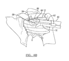
- FIG. 4B is a perspective view of the suture passing instrument of FIG. 1 in an intermediate operative position depicting a suture holder advanced toward the needle tip;
- FIG. 4C is a perspective view of the suture passing instrument of FIG. 1 in an intermediate operative position depicting a suture pusher of the suture holder advancing a suture through the needle tip;
- FIG. 4D is a perspective view of the suture passing instrument of FIG. 1 in an intermediate operative position depicting the pusher of the suture holder retracted from the needle tip;
- FIG. 4E is a perspective view of the suture passing instrument of FIG. 1 in a final retracted position and being removed from the glenohumeral tissue;
- FIG. 4F is a perspective view of the glenohumeral tissue after removal of the suture passing instrument and securement of the suture;
- FIG. 5 is a perspective view of a left-helix suture passing instrument in association with a handle member
- FIG. 6 is a perspective view of a linear curve suture passing instrument in association with a handle member
- FIG. 7 is a perspective view of an alternate carrier body for the suture passing instrument of FIG. 1 ;
- FIG. 8 is a perspective view of an alternate suture passing instrument constructed in accordance with the teachings of the present disclosure.
- FIG. 9A is a perspective view of the suture passing instrument of FIG. 8 in an initial operative position in association with a glenohumeral tissue;
- FIG. 9B is a perspective view of the suture passing instrument of FIG. 8 in an intermediate operative position depicting a suture holder advanced toward a needle tip;
- FIG. 9C is a perspective view of the suture passing instrument of FIG. 8 in an intermediate operative position depicting a pusher of the suture holder advanced through the needle tip;
- FIG. 9D is a perspective view of the suture passing instrument of FIG. 8 in an intermediate operative position depicting the pusher of the suture holder retracted from the needle tip;
- FIG. 9E is a perspective view of the suture passing instrument of FIG. 8 in a final retracted position and being removed from the glenohumeral tissue;
- FIG. 10 is a perspective view of an alternate suture passing instrument constructed in accordance with the teachings of the present disclosure.
- FIG. 11A is a perspective view of the suture passing instrument of FIG. 10 in an initial operative position in association with a glenohumeral tissue;
- FIG. 11B is a perspective view of the suture passing instrument of FIG. 10 in an intermediate operative position depicting a suture holder advanced toward a needle tip;
- FIG. 11C is a perspective view of the suture passing instrument of FIG. 10 in an intermediate operative position depicting a pusher of the suture holder advanced through the needle tip;
- FIG. 11D is a perspective view of the suture passing instrument of FIG. 10 in an intermediate operative position depicting a lock rod advanced toward the needle tip;
- FIG. 11E is a perspective view of the suture passing instrument of FIG. 10 in a final retracted position in association with the glenohumeral tissue;
- FIG. 12 is a perspective view of an alternate suture passing instrument constructed in accordance with the teachings of the present disclosure.
- FIG. 13A is a perspective view of the suture passing instrument of FIG. 12 in an initial operative position in association with a glenohumeral tissue;
- FIG. 13B is a perspective view of the suture passing instrument of FIG. 12 in an intermediate operative position depicting a suture holder advanced toward a needle tip;
- FIG. 13C is a perspective view of the suture passing instrument of FIG. 12 in an intermediate operative position depicting a pusher of the suture holder advanced through the needle tip;
- FIG. 13D is a perspective view of the suture passing instrument of FIG. 12 in an intermediate operative position depicting a wire loop retracted from the needle tip;
- FIG. 13E is a perspective view of the suture passing instrument of FIG. 12 being removed from the glenohumeral tissue;
- FIG. 14A is a perspective view of an alternate suture passing instrument constructed in accordance with the teachings of the present disclosure.
- FIG. 14B is an end view of the alternate suture passing instrument of FIG. 14A .
- FIGS. 1-14 various methods and apparatuses are disclosed according to the present teachings for passing a suture through an exemplary soft tissue, such as a labrum 121 ( FIG. 4A ) within a glenohumeral joint, T.
- an exemplary soft tissue such as a labrum 121 ( FIG. 4A ) within a glenohumeral joint, T.
- the various apparatuses and methods may also be used for a plurality of procedures and to repair other soft tissues in the anatomy, such as those damaged through trauma, overuse, surgical intervention, or disease.
- the various apparatuses and methods should not be limited to use only for tissue damage in the glenohumeral area.
- the various instruments may be used to affix or hold a hamstring, Achilles tendon allograft, other soft tissue, or any other appropriate portion.
- various embodiments may illustrate a suture knot for securing a selected tissue, it will be understood that any mode of securing the afflicted tissue may be used. Therefore, it will be understood that the following discussions are not intended to limit the scope of the present teachings or claims herein.
- Suture passing instrument 10 may be operable for passing a suture 12 ( FIG. 4 ) through the labrum 121 to assist in repairing the joint.
- the various components of the suture passing instrument 10 are made of a biocompatible material, such as stainless steel, to allow for sterilization using chemicals or autoclaving. It is understood that select components described herein can be made from non-stainless steel materials and therefore those select components may not be suitable for all sterilization techniques due to heat sensitivity or chemical sensitivity of the materials.
- suture passing instrument 10 may be a single-use (i.e., disposable) or may be a standardized instrument that can be fitted with removable and replaceable components.
- suture passing instrument 10 is shown to include an operation handle 14 , an elongated shaft or needle member 16 , and a suture holder assembly 18 .
- the operation handle 14 further includes a handle body 20 , an actuator 22 disposed thereon, and a slider mechanism 24 disposed therein.
- the handle body 20 may include at least one opening 26 at a distal end 28 for receiving the needle member 16 and the suture holder assembly 18 , a central cavity 30 for receipt of a first slide member 32 , and a plurality of curved channels 34 integrally formed in the handle body 20 for receipt of a second slide member 36 .
- the slider mechanism 24 may include the pivotally attached first and second slide members 32 , 36 , a c-shaped translation member 38 , and a spring 40 .
- the first and second slide members 32 , 36 may move longitudinally along the central cavity 30 and curved channels 34 , respectively.
- the curved channels 34 may be mirrored about a center axis, A, of the operation handle 14 to allow for a single design for right- and left-handed handles.
- the handle body 20 may be formed from any biocompatible material (e.g., metal or polymer) and may also include a textured exterior surface 42 (e.g., knurl, padding) to provide comfort and/or grip for the operator.
- the actuator 22 may be a trigger member operable for actuating the slider mechanism 24 in a longitudinal direction along the handle body 20 from a first or retracted position (as shown in FIGS. 1 and 1A ) to a second or extended position (as shown in FIGS. 4C and 1B ). It is also contemplated that the actuator 22 may include multiple members 44 moving in tandem or moving independently (e.g., as shown in phantom in FIG. 6 ). The actuator 22 may define a centrally-raised, finger grip portion 46 for assisting an operator in movement between the retracted and extended positions. Although not shown, the actuator 22 may also incorporate the textured exterior surface (e.g., knurl, padding) to provide comfort and/or grip for the operator.
- the actuator 22 may also incorporate the textured exterior surface (e.g., knurl, padding) to provide comfort and/or grip for the operator.
- the needle member 16 and suture holder assembly 18 may extend from the distal end 28 of the handle body 20 . Furthermore, the needle member 16 and suture holder assembly 18 may have a connection member 48 located therebetween. Both the needle member 16 and suture holder assembly 18 may be fixedly coupled to the operation handle 14 and the connection member 48 to maintain a parallel relationship and to prevent relative movement therebetween. It should be understood that the connection member 48 may be any device for securing the needle member 16 and the suture holder assembly 18 together, including but not limited to, an adhesive, a weld, and a fastener.
- the needle member 16 may include a straight elongated shaft 50 , a helical end 52 integrally formed with the elongated shaft 50 , a needle eyelet 54 extending through the helical end 52 , and a pointed tip 56 at a distal end 58 of the needle member 16 .
- the elongated shaft 50 extends along a longitudinal axis, X, and has a first, proximal end 60 extending from the distal end 28 of the handle body 20 and a second, distal end 62 terminating a predetermined distance beyond the connection member 48 .
- the helical end 52 may extend from the second end 62 of the elongated shaft 50 and may exhibit a “pig-tail” shape or right helix curve over its length.
- the right helix curve may follow the path of a spiral or a straight line drawn on a plane when that plane is wrapped around a cylindrical surface, such as a right circular cylinder. Accordingly, the helical end 52 may be rotated to bring a centerline, C, of the needle eyelet 54 into a coaxial arrangement with a longitudinal axis, Y, of the suture holder assembly 18 .
- the longitudinal axis, X, of the elongated shaft 50 and the longitudinal axis, Y, of the suture holder assembly 18 are generally parallel to one another along their lengths.
- the needle eyelet 54 may define a generally hexagonal periphery 70 symmetrically arranged about a plane extending from the pointed tip 56 and through centerline, C. Furthermore, the needle eyelet 54 may define a pair of opposed semi-circular openings 72 arranged at and extending from distal and proximal ends 74 , 76 of the hexagonal periphery 70 . The semi-circular openings 72 may have pointed, opposed ends 78 terminating at the hexagonal periphery 70 for gripping the suture 12 , as will be described in more detail below.
- suture holder assembly 18 may include a generally straight tubular shaft 80 , a tubular extension rod 82 telescopically received within the tubular shaft 80 , a cannulated suture carrier 84 at a distal end 86 of the tubular extension rod 82 , and a suture pusher 88 telescopically arranged within the cannulated suture carrier 84 .
- the generally tubular shaft 80 extends along the longitudinal axis, Y, and has a first, proximal end 90 extending from the distal end 28 of the handle body 20 and a second, distal end 92 terminating at the connection member 48 .
- the tubular extension rod 82 is coupled to or in communication with both the actuator 22 and the cannulated suture carrier 84 . Therefore, movement of actuator 22 causes movement of the tubular extension rod 82 , as will be described in more detail below.
- Cannulated suture carrier 84 may define a carrier body 94 having a pair of opposing, parallel channels 96 , and an extended nose portion 98 .
- the parallel channels 96 may have a predetermined length extending into the carrier body 94 and may have a width for receipt of sutures of various sizes. Accordingly, the parallel channels 96 may have sidewalls 100 that are angled ( FIG. 2 ) or sidewalls 500 arranged in a decreasing step arrangement ( FIG. 7 ).
- the nose portion 98 may extend outwardly from the carrier body 94 in a generally spade-shaped configuration, terminating at a nose tip 102 .
- the nose tip 102 may be located adjacent to the needle member 16 .
- the nose portion 98 may be angled to direct the suture 12 ( FIG. 4A ) into the parallel channels 96 of the carrier body 94 during loading of the suture 12 .
- the suture pusher 88 may define a generally cylindrical pusher body 104 , a pair of vertically-oriented, parallel surfaces 106 , 108 , and a channel or hook member 110 extending inwardly from a distal end 112 thereof.
- the suture pusher 88 may be sized to be movably received within the eyelet 54 of the needle member 16 .
- the reduction in size from the generally cylindrical pusher body 104 to the integrally formed parallel surfaces 106 , 108 allows for ingress of the suture 12 ( FIG. 4A ) within the eyelet 54 of the needle member 16 .
- the hook member 110 may be a semi-circular indentation within the distal end 112 of the suture pusher 88 .
- the hook member 110 may be any shape for retaining the suture 12 during movement of the suture pusher 88 towards the eyelet 54 of the needle member 16 .
- the suture pusher 88 may extend through the tubular extension rod 82 and the tubular shaft 80 for direct connection with the first slide member 32 in the operation handle 14 .
- the spring 40 may extend over the suture pusher 88 in the operation handle 14 and abut the first slide member 32 .
- the c-shaped translation member 38 may also extend over the suture pusher 88 in the operation handle 14 and may abut the other side of the spring 40 so as to contain the spring 40 between the c-shaped translation member 38 and the first slide member 32 .
- the tubular extension rod 82 may be fixedly attached to the c-shaped translation member 38 opposite the spring 40 .
- the second slide member 36 may include an extending pin 114 drivingly contacting the c-shaped translation member 38 .
- the extending pin 114 may be located at a central portion 116 between a short leg 118 and a parallel long leg 120 of the c-shaped translation member 38 .
- the actuator 22 moves to the extended position
- the second slide member 36 moves along the curved channel 34 .
- the extending pin 114 contacts the short leg 118 causing it to move longitudinally, as well.
- the extending pin 114 curves away from the short leg 118 along the channel 34 , removing the longitudinal translation force from the c-shaped translation member 38 .
- the labrum 121 of the glenohumeral joint, T shown in FIGS. 4-4F and the slider mechanism 24 shown in FIGS. 1A and 1B .
- the labrum 121 is depicted in detail in FIG. 4A as it is within the glenohumeral joint, T, but it is obstructed from view in the other figures in order to shown positioning of the helix in the tissue. It should be understood that the repair as described herein is being completed on the labrum 121 . Initially with the actuator 22 in the retracted position, the appropriately sized suture 12 is loaded into the parallel channels 96 of the cannulated suture carrier 84 .
- the suture 12 may be loaded transversely to the longitudinal axis, Y, by dragging the suture 12 along the incline of the nose portion 98 .
- the angle of the sidewalls 100 may allow the suture 12 to extend within the parallel channels 96 to be removably retained therewith.
- the pointed tip 56 of the helical end 52 is brought into contact with the labrum 121 of the glenohumeral joint, T, with no rotational movement.
- the sharpened point of the tip 56 pierces the ligament, T, and allows the suture passing instrument 10 to establish an opening 122 within the labrum 121 within the joint, T.
- the operation handle 14 is rotated in a counter-clockwise manner, as shown by rotational arrow 124 , in order to maintain a minimal size for the opening 122 .
- the operation handle 14 may be rotated anywhere between approximately one-quarter of a turn to one full revolution to extend the needle eyelet 54 out of the ligament, T.
- the amount of rotation for the operation handle 14 may depend upon the dimensional shape of the curve of the helical end 52 .
- the final orientation of the helical end 52 is shown in phantom.
- the actuator 22 is moved to the extended position.
- the actuator 22 is fixedly attached to the slider mechanism 24 , so that longitudinal movement of the actuator 22 to the extended position, in turn, causes movement of the slider mechanism 24 .
- the actuator 22 drives the slider mechanism 24 towards the distal end 28 of the handle body 20 .
- This longitudinal movement causes the first and second slide members 32 , 36 to translate in the central cavity 30 and curved channels 34 , respectively.
- the extending pin 114 of the second slide member 36 drivingly moves the short leg 118 of the c-shaped translation member 38 .
- the concurrent movement of the first slide member 32 and the c-shaped translation member 38 cause the tubular extension rod 82 and the suture pusher 88 to extend through the tubular shaft 80 at an equivalent speed. Accordingly, the tubular extension rod 82 and suture pusher 88 of the suture holder assembly 18 move distally out of the tubular shaft 80 directing the cannulated suture carrier 84 towards the needle eyelet 54 .
- the extending pin 114 curves away from the short leg 118 along the channel 34 , removing its longitudinal driving force.
- the c-shaped translation member 38 may then contact a stop 128 located at the distal end 28 of the handle body 20 , preventing any further longitudinal movement of the c-shaped translation member 38 and the tubular extension rod 82 .
- This stopped motion of the c-shaped translation member 38 equates to a stopped motion of the cannulated suture carrier 84 when the nose portion 98 extends over the helical end 52 of the needle member 16 and the cannulated suture carrier 84 extends to a predetermined distance away from the needle member 16 .
- the first slide member 32 continues its longitudinal translation through the central cavity 30 , compressing the spring 40 as it moves.
- the suture pusher 88 continues movement with the first slide member 32 , which causes its extension from the tubular extension rod 82 and the cannulated suture carrier 84 .
- the hook member 110 captures the suture 12 retained by the parallel channels 96 of the cannulated suture carrier 84 and pulls the suture 12 out of the channels 96 .
- the hook member 110 and at least a portion of the parallel surfaces 106 , 108 extend through the needle eyelet 54 , forcing the suture 12 therethrough.
- the suture 12 may be eased towards the semi-circular openings 72 by the tapered shape of the suture pusher 88 and by arrangement of the angled shape of the hexagonal periphery 70 .
- the opposed ends 78 of the semi-circular openings 72 may then receive the suture 12 for retention therewith. It should be understood that the opposed ends 78 might slightly flex as the suture 12 is eased towards the semi-circular openings 72 . Furthermore, the opposed ends 78 may “bite” into fibers of the suture 12 to provide the requisite retention for the suture 12 .
- the operator may then return the actuator 22 to the retracted position. During retraction, the operator may remove the longitudinal force from the actuator 22 allowing the first slide member 32 to snap back from the distal end 28 of the handle body 20 due to force from the spring 40 .
- the suture pusher 88 likewise, returns to its initial position within the cannulated suture carrier 84 .
- the actuator 22 is returned to the retracted position by applying a reverse longitudinal force therewith.
- the actuator 22 drives the slider mechanism 24 towards a proximal end 130 of the handle body 20 .
- This longitudinal movement causes the first and second slide members 32 , 36 to translate in a reverse direction in the central cavity 30 and curved channels 34 .
- the extending pin 114 curves back towards the c-shaped translation member 38 and drivingly engages the long leg 120 of the c-shaped translation member 38 .
- the concurrent movement of the first slide member 32 and the c-shaped translation member 38 cause the tubular extension rod 82 and the suture pusher 88 to retract into the tubular shaft 80 . Accordingly, the cannulated suture carrier 84 is withdrawn by the reverse movement of the tubular extension rod 82 . Notably, however, the suture 12 is captured within the needle eyelet 54 . The needle member 16 may then be withdrawn from the ligament, T, carrying the suture 12 therewith. Withdrawal of the needle member 16 is accomplished in reverse of insertion (i.e., rotation occurs in a clockwise motion), as shown by rotational arrow 132 , with the needle member 16 being removed from the ligament, T, at the opening 122 .
- the suture 12 is then threaded through the opening 122 within the glenohumeral ligament, T. Ends of the suture 12 can then be knotted 134 outside of the surgical opening for a minimally invasive repair.
- Suture passing instrument 200 is also operable for passing the suture 12 through the labrum 121 to assist in repairing the joint, as previously described with respect to suture passing instrument 10 . Furthermore, many of the components of suture passing instrument 10 remain unchanged in suture passing instrument 200 . For example, suture passing instrument 200 uses a similar operation handle 14 and suture holder assembly 18 . Suture passing instrument 200 , however, exhibits a left helix curve at a helical end 252 of a needle member 216 , instead of the right helix curve described with respect to the suture passing instrument 10 .
- suture passing instrument 10 and suture passing instrument 200 are highly similar, certain surgeons may prefer one design to the other due to right- or left-hand dominance or for other reasons not articulated herein.
- Suture passing instrument 300 is also operable for passing the suture 12 through the labrum 121 to assist in repairing the joint, as previously described with respect to suture passing instrument 10 . Furthermore, many of the components of suture passing instrument 10 remain unchanged in suture passing instrument 300 . For example, suture passing instrument 300 uses a similar operation handle 14 and suture holder assembly 18 . Suture passing instrument 300 , however, exhibits a linear curve (i.e., “ice cream scoop”) at an end 352 of a needle member 316 , instead of the right helix curve at the helical end 52 described with respect to the suture passing instrument 10 .
- a linear curve i.e., “ice cream scoop”
- the operation handle 14 need only to be moved in a single plane in order to maintain the minimal size for the opening 122 .
- suture passing instrument 10 and suture passing instrument 300 are highly similar, certain surgeons may prefer one design to the other due to space considerations or for other reasons not articulated herein.
- FIG. 7 another alternative suture passing instrument 400 is shown having an alternate cannulated suture carrier 484 associated with the tubular extension rod 82 .
- Cannulated suture carrier 484 is operable for receiving the suture 12 and directing it towards the needle eyelet 54 , as described with respect to cannulated suture carrier 84 .
- many of the components of cannulated suture carrier 84 remain unchanged in cannulated suture carrier 484 .
- Cannulated suture carrier 484 includes a pair of extending nose portions 498 mirrored about a pair of opposing, parallel channels 496 .
- the parallel channels 496 may have a predetermined length extending into a carrier body 494 of the cannulated suture carrier 484 . Accordingly, the parallel channels 496 may have sidewalls 500 that are angled for receipt of the suture 12 .
- the extending nose portions 498 may extend outwardly from the carrier body 494 in a generally spade-shaped configuration, terminating at a pair of nose tips 502 .
- the nose portions 498 may be interiorly angled towards the parallel channels 496 , so as to direct the suture 12 into the parallel channels 496 of the carrier body 494 during suture 12 loading.
- the nose tips 502 may also exhibit an exterior curve 536 with the carrier body 494 in order to gently push tissue away from the needle eyelet 54 during operation.
- Suture passing instrument 600 is also operable for passing a suture through the labrum 121 of the glenohumeral joint, T, to assist in repairing the tissue, as previously described with respect to suture passing instrument 10 .
- suture passing instrument 600 uses a similar operation handle 14 and connection member 48 , which are not shown and will not be described in detail herein.
- suture passing instrument 600 includes both an alternately designed needle member 616 and suture holder assembly 618 extending from the distal end 28 of the operation handle 14 . Both the needle member 616 and the suture holder assembly 618 may be fixedly coupled to the operation handle 14 and the connection member 48 to maintain a parallel relationship and to prevent relative movement therebetween.
- the needle member 616 may include an elongated shaft 650 , a helical end 652 secured to the elongated shaft 650 , a needle eyelet 654 extending through the helical end 652 , and a pointed tip 656 at a distal end 658 of the helical end 652 . While this embodiment depicts the helical end 652 removable from the elongated shaft 650 , it should be understood that the elongated shaft 650 and helical end 652 might also be integrally formed as shown in the aforementioned embodiments. While certain embodiments herein discuss either a removable or integrally formed needle member, it should be understood that each embodiment of the suture passing instrument may incorporate either of the removable or integrally formed needle member.
- the removable needle member may be connected to the elongated shaft through any known means, such as, bayonet slot, threading, or interference fit. Furthermore, the removable needle member may be selected from a plurality of needle members or from a pre-packaged kit.
- the elongated shaft 650 may extend along a longitudinal axis, X, a predetermined distance from the operation handle 14 .
- the helical end 652 may extend from a distal end 662 of the elongated shaft 650 and may exhibit a “pig-tail” shape or helix curve over its length.
- the helix curve may be rotated either in a right- or left-handed direction to bring a centerline, C, of the needle eyelet 654 into a coaxial arrangement with a longitudinal axis, Y, of the suture holder assembly 618 .
- the needle eyelet 654 may define a generally circular profile 670 having an opening 638 .
- the opening 638 may define a pair of opposing faces 640 , 642 extending from the circular profile 670 and through the pointed tip 656 .
- the needle eyelet 654 In a relaxed state, the needle eyelet 654 may have a first diameter as shown.
- the needle eyelet 654 may be expandable to a second diameter for receipt of the suture 12 , wherein the opposing faces 640 , 642 are biased apart, as will be described in more detail below.
- Suture holder assembly 618 may include a generally tubular shaft 680 , a cannulated suture carrier 684 telescopically received within the tubular shaft 680 , and a suture pusher 688 telescopically received within the cannulated suture carrier 684 .
- the generally tubular shaft 680 extends along the longitudinal axis, Y, and has a distal end 692 terminating near the distal end 662 of the elongated shaft 650 of the needle member 616 .
- Cannulated suture carrier 684 may define a pair of opposing, parallel channels 696 having a predetermined length extending into the cannulated suture carrier 684 and may have a width for receipt of sutures of various sizes.
- the parallel channels 696 may have sidewalls 602 that are angled or arranged in a decreasing step arrangement.
- the suture pusher 688 may define a generally cylindrical pusher body 604 sized to be received within the eyelet 654 of the needle member 616 . While suture passing instrument 600 is shown to include suture holder assembly 618 , it is also contemplated that the suture holder assembly 18 may be used with this embodiment. As should be understood, each embodiment may interchange the suture holder assembly 18 and the suture holder assembly 618 .
- the pointed tip 656 of the helical end 652 is brought into contact with the labrum 121 ( FIG. 4A ) of the glenohumeral joint, T, with no rotational movement.
- the sharpened point of the tip 656 pierces the ligament, T, and allows the suture passing instrument 600 to establish an opening 622 within the ligament, T.
- the operation handle 14 is rotated in a counter-clockwise manner, as shown by rotational arrow 624 , in order to maintain a minimal size for the opening 622 , as previously described.
- the operation handle 14 may be rotated anywhere between approximately one-quarter of a turn to one full revolution to extend the needle eyelet 654 out of the ligament, T.
- the amount of rotation for the operation handle 14 may depend upon the dimensional shape of the curve of the helical end 652 .
- the final orientation of the helical end 652 is shown in phantom.
- the actuator 22 is moved to the extended position.
- the actuator 22 is fixedly attached to the slider mechanism 24 , so that longitudinal movement of the actuator 22 to the extended position, in turn, causes movement of the slider mechanism 24 .
- the actuator 22 drives the slider mechanism 24 towards the distal end 28 of the handle body 20 .
- This longitudinal movement causes the first and second slide members 32 , 36 to translate in the central cavity 30 and curved channels 34 , respectively.
- the extending pin 114 of the second slide member 36 drivingly moves the short leg 118 of the c-shaped translation member 38 .
- the concurrent movement of the first slide member 32 and the c-shaped translation member 38 cause the cannulated suture carrier 684 and the suture pusher 688 to extend through the tubular shaft 680 at an equivalent speed. Accordingly, the cannulated suture carrier 684 of the suture holder assembly 618 moves distally outwardly from the tubular shaft 680 directing the suture 12 towards the needle eyelet 654 .
- the extending pin 114 curves away from the short leg 118 , removing its longitudinal driving force.
- the c-shaped translation member 38 may then contact the stop 128 located at the distal end 28 of the handle body 20 , preventing any further longitudinal movement of the c-shaped translation member 38 and the cannulated suture carrier 684 .
- This stopped motion of the c-shaped translation member 38 equates to a stopped motion of the cannulated suture carrier 684 a predetermined distance from the eyelet 654 of the needle member 616 .
- the first slide member 32 continues its longitudinal translation through the central cavity 30 , compressing the spring 40 as it moves.
- the suture pusher 688 continues movement with the first slide member 32 , which causes its extension from the cannulated suture carrier 684 . In this motion, the suture pusher 688 forces the suture 12 out of the channels 696 . At least a portion of the suture pusher 688 extends through the needle eyelet 654 , expanding the needle eyelet 654 at the opening 638 . This expansion biases the opposing faces 640 , 642 of the opening 638 apart and flexes the needle eyelet 654 to the enlarged, second diameter. The suture 12 can then be pushed into the eyelet 654 .
- the operator may then return the actuator 22 to the retracted position. During retraction, the operator may remove the longitudinal force from the actuator 22 allowing the first slide member 32 to snap back from the distal end 28 of the handle body 20 due to force from the spring 40 .
- the suture pusher 688 likewise, returns to its initial position within the cannulated suture carrier 684 . Notably, after removing the suture pusher 688 from the needle eyelet 654 , the needle eyelet 654 returns to the first diameter contracted around the suture 12 .
- the actuator 22 is returned to the retracted position by applying a reverse longitudinal force therewith.
- the actuator 22 drives the slider mechanism 24 towards the proximal end 130 of the handle body 20 .
- This longitudinal movement causes the first and second slide members 32 , 36 to translate in a reverse direction in the central cavity 30 and curved channels 34 .
- the extending pin 114 curves back towards the c-shaped translation member 38 and drivingly engages the long leg 120 of the c-shaped translation member 38 .
- the concurrent movement of the first slide member 32 and the c-shaped translation member 38 cause the cannulated suture carrier 684 and the suture pusher 688 to retract into the tubular shaft 680 .
- the suture 12 remains captured within the needle eyelet 654 .
- the needle member 616 may then be withdrawn from the ligament, T, carrying the suture 12 therewith. Withdrawal of the needle member 616 is accomplished in reverse of insertion (i.e., rotation occurs in a clockwise motion), as shown by rotational arrow 632 , with the needle member 616 being removed from the ligament, T, at the tissue opening 622 . Ends of the suture 12 can then be knotted 134 outside of the surgical site, as previously shown in FIG. 4F .
- Suture passing instrument 700 is also operable for passing a suture through the labrum 121 of the glenohumeral joint, T, to assist in repairing the tissue, as previously described with respect to suture passing instrument 10 .
- suture passing instrument 700 uses a similar operation handle 14 and connection member 48 , which are not shown and will not be described in detail herein.
- suture passing instrument 700 includes both an alternately designed cannulated needle member 716 and suture holder assembly 718 extending from the distal end 28 of the operation handle 14 . Both the cannulated needle member 716 and suture holder assembly 718 may be fixedly coupled to the operation handle 14 and the connection member 48 to maintain a parallel relationship and to prevent relative movement therebetween.
- the cannulated needle member 716 may include an elongated shaft 750 , a tubular helical end 752 secured to the elongated shaft 750 , a generally circular needle eyelet 754 (best shown in FIG. 11A ) extending through the helical end 752 , a pointed tip 756 at a distal end 758 of the helical end 752 , and a lock rod 740 movable within the elongated shaft 750 ( FIG. 11A ). While this embodiment depicts the helical end 752 separable from the elongated shaft 750 , it should be understood that the elongated shaft 750 and helical end 752 may also be integrally formed as shown in the aforementioned embodiments.
- the elongated shaft 750 may extend along a longitudinal axis, X, a predetermined distance from the operation handle 14 .
- the helical end 752 may extend from a distal end 762 of the elongated shaft 750 and may exhibit a “pig-tail” shape or helix curve over its length.
- the helix curve may be rotated either in a right- or left-handed direction to bring a centerline, C, of the needle eyelet 754 into a coaxial arrangement with a longitudinal axis, Y, of the suture holder assembly 718 .
- the needle eyelet 754 may define a generally circular profile 770 extending through opposite sides of the tubular surface of the cannulated needle member 716 .
- the lock rod 740 may be movable from a first, retracted position within the elongated shaft 750 to a second, extended position in the helical end 752 . In the extended position, the lock rod 740 may extend transversely between the opposite sides of the tubular surface at the needle eyelet 754 . Accordingly, a blunt end 742 of the lock rod 740 may terminate distal the needle eyelet 754 .
- the lock rod 740 may be formed from a flexible material (e.g., nitinol) which can bend through the cannulated needle member 716 .
- Suture holder assembly 718 may include a generally tubular shaft 780 , a cannulated suture carrier 784 telescopically received within the tubular shaft 780 , and a suture pusher 788 telescopically received within the cannulated suture carrier 784 .
- the generally tubular shaft 780 extends along the longitudinal axis, Y, and has a distal end 792 terminating near the distal end 762 of the elongated shaft 750 of the needle member 716 .
- Cannulated suture carrier 784 may define a pair of opposing, parallel channels 796 having a predetermined length extending into the cannulated suture carrier 784 and may have a width for receipt of sutures of various sizes.
- the parallel channels 796 may have sidewalls 702 that are angled or arranged in a decreasing step arrangement.
- the suture pusher 788 may define a generally cylindrical pusher body 704 sized to be received within the eyelet 754 of the needle member 716 . While suture passing instrument 700 is shown to include suture holder assembly 718 , it is also contemplated that the suture holder assembly 18 may be used with this embodiment. As should be understood, each embodiment may interchange the suture holder assembly 18 and the suture holder assembly 718 .
- the suture passing instrument 700 will now be described with reference to the glenohumeral ligament, T, shown in FIGS. 11A-11E and the slider mechanism 24 shown in FIGS. 1A and 1B .
- the appropriately sized suture 12 is loaded into the parallel channels 796 of the cannulated suture carrier 784 transversely to the longitudinal axis, Y.
- the pointed tip 756 of the helical end 752 is brought into contact with the labrum 121 ( FIG. 4A ) of the glenohumeral joint, T, with no rotational movement.
- the sharpened point of the tip 756 pierces the ligament, T, and allows the suture passing instrument 700 to establish an opening 722 within the ligament, T.
- the operation handle 14 is rotated in a counter-clockwise manner, as shown by rotational arrow 724 , in order to maintain a minimal size for the opening 722 , as previously described.
- the operation handle 14 may be rotated anywhere between approximately one-quarter of a turn to one full revolution to extend the needle eyelet 754 out of the ligament, T.
- the amount of rotation for the operation handle 14 may depend upon the dimensional shape of the curve of the helical end 752 .
- the final orientation of the helical end 752 is shown in phantom.
- the actuator 22 is moved to the extended position.
- the actuator 22 is fixedly attached to the slider mechanism 24 , so that longitudinal movement of the actuator 22 to the extended position, in turn, causes movement of the slider mechanism 24 .
- the actuator 22 drives the slider mechanism 24 towards the distal end 28 of the handle body 20 .
- This longitudinal movement causes the first and second slide members 32 , 36 to translate in the central cavity 30 and curved channels 34 , respectively.
- the extending pin 114 of the second slide member 36 drivingly moves the short leg 118 of the c-shaped translation member 38 .
- the concurrent movement of the first slide member 32 and the c-shaped translation member 38 cause the cannulated suture carrier 784 and the suture pusher 788 to extend through the tubular shaft 780 at an equivalent speed. Accordingly, the cannulated suture carrier 784 of the suture holder assembly 718 moves distally outwardly from the tubular shaft 780 directing the suture 12 towards the needle eyelet 754 .
- the extending pin 114 curves away from the short leg 118 , removing its longitudinal driving force.
- the c-shaped translation member 38 may then contact the stop 128 located at the distal end 28 of the handle body 20 , preventing any further longitudinal movement of the c-shaped translation member 38 and the cannulated suture carrier 784 .
- This stopped motion of the c-shaped translation member 38 equates to a stopped motion of the cannulated suture carrier 784 a predetermined distance from the eyelet 754 of the needle member 716 .
- the first slide member 32 continues its longitudinal translation through the central cavity 30 , compressing the spring 40 as it moves.
- the suture pusher 788 continues movement with the first slide member 32 , which causes its extension from the cannulated suture carrier 784 . In this motion, the suture pusher 788 forces the suture 12 out of the channels 796 . At least a portion of the suture pusher 788 extends through the needle eyelet 754 , pushing the suture 12 into the eyelet 754 .
- the operator may remove the longitudinal force from the actuator 22 allowing the first slide member 32 to snap back from the distal end 28 of the handle body 20 due to force from the spring 40 .
- the lock rod 740 may then be advanced through the cannulated needle member 716 to pinch the suture 12 against the circular profile 770 with the blunt end 742 , by advancing a second actuator (shown in phantom in FIG. 6 as member 44 ). The operator may then return the actuator 22 to the retracted position.
- lock rod 740 may be advanced and retracted in a single actuation motion (e.g., as a continuous motion from the actuator 22 as shown and described with respect to the operation handle and slider mechanism of copending U.S. Ser. No. 13/114,483 filed concurrently herewith; U.S. Provisional Application No. 61/348,016, filed on May 25, 2010) the disclosure of which is incorporated by reference herein in its entirety).
- the suture pusher 788 returns to its initial position within the cannulated suture carrier 784 and the cannulated suture carrier 784 is captured by the tubular shaft 780 , as previously described with respect to the suture carrier 684 .
- the suture 12 remains within the needle eyelet 754 , retained by the blunt end 742 of the lock rod 740 .
- the needle member 716 may then be withdrawn from the ligament, T, carrying the suture 12 therewith. Withdrawal of the needle member 716 is accomplished in reverse of insertion (i.e., rotation occurs in a clockwise motion), as shown by rotational arrow 732 , with the needle member 716 being removed from the ligament, T, at the tissue opening 722 . Ends of the suture 12 can then be knotted 134 outside of the surgical site, as previously shown in FIG. 4F .
- Suture passing instrument 800 is also operable for passing the suture 12 through the labrum 121 of the glenohumeral joint, T, to assist in repairing the tissue, as previously described with respect to suture passing instrument 10 .
- suture passing instrument 800 uses a similar operation handle 14 and connection member 48 , which are not shown and will not be described in detail herein.
- suture passing instrument 800 includes both an alternately designed cannulated needle member 816 and suture holder assembly 818 extending from the distal end 28 of the operation handle 14 . Both the cannulated needle member 816 and suture holder assembly 818 may be fixedly coupled to the operation handle 14 and the connection member 48 to maintain a parallel relationship and to prevent relative movement therebetween.
- the cannulated needle member 816 may include an elongated shaft 850 , a tubular helical end 852 secured to the elongated shaft 850 , a generally circular needle eyelet 854 extending through the helical end 852 , a pointed tip 856 at a distal end 858 of the helical end 852 , and a wire loop 840 extending through the elongated shaft 850 to the helical end 852 and surrounding the circular needle eyelet 854 . While this embodiment depicts the helical end 852 separable from the elongated shaft 850 , it should be understood that the elongated shaft 850 and the helical end 852 may also be integrally formed as shown in the aforementioned embodiments.
- the elongated shaft 850 may extend along a longitudinal axis, X, a predetermined distance from the operation handle 14 .
- the helical end 852 may extend from a distal end 862 of the elongated shaft 850 and may exhibit a “pig-tail” shape or helix curve over its length.
- the helix curve may be rotated either in a right- or left-handed direction to bring a centerline, C, of the needle eyelet 854 into a coaxial arrangement with a longitudinal axis, Y, of the suture holder assembly 818 .
- the needle eyelet 854 may define a generally circular profile 870 extending through opposite sides of the tubular surface of the cannulated needle member 816 (see FIG. 12A ). Furthermore, the wire loop 840 may be movable from a first, extended position to a second, retracted position, both within the helical end 852 surrounding the needle eyelet 854 .
- the wire loop 840 may be a material (e.g., nitinol) that generally maintains its biased open loop shape in both the extended and retracted positions, as will be described in more detail below.
- Suture holder assembly 818 may include a generally tubular shaft 880 , a cannulated suture carrier 884 telescopically received within the tubular shaft 880 , and a suture pusher 888 telescopically received within the cannulated suture carrier 884 .
- the generally tubular shaft 880 extends along the longitudinal axis, Y, and has a distal end 892 terminating near the distal end 862 of the elongated shaft 850 of the needle member 816 .
- Cannulated suture carrier 884 may define a pair of opposing, parallel channels 896 having a predetermined length extending into the cannulated suture carrier 884 and may have a width for receipt of sutures of various sizes.
- the parallel channels 896 may have sidewalls 802 that are angled or arranged in a decreasing step arrangement.
- the suture pusher 888 may define a generally cylindrical pusher body 804 sized to be received within the eyelet 854 of the needle member 816 .
- suture passing instrument 800 is shown to include suture holder assembly 818 , it is also contemplated that the suture holder assembly 18 may be used with this embodiment. As should be understood, each embodiment may interchange the suture holder assembly 18 and the suture holder assembly 818 .
- the suture passing instrument 800 will now be described with reference to the glenohumeral ligament, T, shown in FIGS. 13A-13E and the slider mechanism 24 shown in FIGS. 1A and 1B .
- the appropriately sized suture 12 is loaded into the parallel channels 896 of the cannulated suture carrier 884 transversely to the longitudinal axis, Y.
- the pointed tip 856 of the helical end 852 is brought into contact with the labrum 121 ( FIG. 4A ) of the glenohumeral joint, T, with no rotational movement.
- the sharpened point of the tip 856 pierces the ligament, T, and allows the suture passing instrument 800 to establish an opening 822 within the ligament, T.
- the operation handle 14 is rotated in a counter-clockwise manner, as shown by rotational arrow 824 , in order to maintain a minimal size for the opening 822 , as previously described.
- the operation handle 14 may be rotated anywhere between approximately one-quarter of a turn to one full revolution to extend the needle eyelet 854 out of the ligament, T.
- the amount of rotation for the operation handle 14 may depend upon the dimensional shape of the curve of the helical end 852 .
- the final orientation of the helical end 852 is shown in phantom.
- the actuator 22 is moved to the extended position.
- the actuator 22 is fixedly attached to the slider mechanism 24 , so that longitudinal movement of the actuator 22 to the extended position, in turn, causes movement of the slider mechanism 24 .
- the actuator 22 drives the slider mechanism 24 towards the distal end 28 of the handle body 20 .
- This longitudinal movement causes the first and second slide members 32 , 36 to translate in the central cavity 30 and curved channels 34 , respectively.
- the extending pin 114 of the second slide member 36 drivingly moves the short leg 118 of the c-shaped translation member 38 .
- the concurrent movement of the first slide member 32 and the c-shaped translation member 38 cause the cannulated suture carrier 884 and the suture pusher 888 to extend through the tubular shaft 880 at an equivalent speed. Accordingly, the cannulated suture carrier 884 of the suture holder assembly 818 moves distally outwardly from the tubular shaft 880 directing the suture 12 towards the needle eyelet 854 .
- the extending pin 114 curves away from the short leg 118 , removing its longitudinal driving force.
- the c-shaped translation member 38 may then contact the stop 128 located at the distal end 28 of the handle body 20 , preventing any further longitudinal movement of the c-shaped translation member 38 and the cannulated suture carrier 884 .
- This stopped motion of the c-shaped translation member 38 equates to a stopped motion of the cannulated suture carrier 884 a predetermined distance from the eyelet 854 of the needle member 816 .
- the first slide member 32 continues its longitudinal translation through the central cavity 30 , compressing the spring 40 as it moves.
- the suture pusher 888 continues movement with the first slide member 32 , which causes its extension from the cannulated suture carrier 884 . In this motion, the suture pusher 888 forces the suture 12 out of the channels 896 . At least a portion of the suture pusher 888 extends through the needle eyelet 854 , pushing the suture 12 into the eyelet 854 .
- the operator may remove the longitudinal force from the actuator 22 allowing the first slide member 32 to snap back from the distal end 28 of the handle body 20 due to force from the spring 40 .
- the wire loop 840 may then be retracted within the cannulated needle member 816 to pinch the suture 12 against the circular profile 870 of the eyelet 854 , by advancing a second actuator (shown in phantom in FIG. 6 as member 44 ). The operator may then return the actuator 22 to the retracted position.
- the wire loop 840 may be advanced and retracted in a single actuation motion (e.g., as a continuous motion from the actuator 22 as previously described with respect to lock rod 740 .
- the suture pusher 888 returns to its initial position within the cannulated suture carrier 884 and the cannulated suture carrier 884 is captured by the tubular shaft 880 , as previously described with respect to the suture carrier 684 .
- the suture 12 remains within the needle eyelet 854 , pinched against the needle eyelet 854 with the wire loop 840 .
- the needle member 816 may then be withdrawn from the ligament, T, carrying the suture 12 therewith. Withdrawal of the needle member 816 is accomplished in reverse of insertion (i.e., rotation occurs in a clockwise motion), as shown by rotational arrow 832 , with the needle member 816 being removed from the ligament, T, at the tissue opening 822 . Ends of the suture 12 can then be knotted 134 outside of the surgical site, as previously shown in FIG. 4F .
- Suture passing instrument 900 is also operable for passing the suture 12 through the labrum 121 to assist in repairing the joint, as previously described with respect to suture passing instrument 10 . Furthermore, many of the components of the suture passing instrument 10 remain unchanged in suture passing instrument 900 . For example, suture passing instrument 900 uses a similar operation handle 14 and suture holder assembly 18 . Suture passing instrument 900 , however, exhibits an elongated helix curve at a helical end 952 of a needle member 916 , rather than the helix curve described with respect to the suture passing instrument 10 .
- the elongated helix curve may follow a constant radius rotated about a central axis of the needle member 916 , stop rotation and extend along a straight length, L, then continue following the constant radius rotated about the central axis of the needle member 916 .
- Both the suture passing instrument 10 and the suture passing instrument 900 will exhibit a similar end view as shown in FIG. 14B (elongated straight length, L, shown in phantom).
- the suture passing instrument 900 defines an elongated section, L, which may be at least as large as a height section, H.
- the elongated section, L, and the height section, H form a trough which is substantially longer than the trough created by the helix of suture passing instrument 10 .
- Such an arrangement allows more tissue to be captured by the suture passing instrument 900 without increasing the size of the cannulated needle member 916 as compared to a traditional helix shape. While suture passing instrument 10 and suture passing instrument 900 are highly similar, certain surgeons may prefer one design to the other due to the amount of tissue needing to be secured.
- connection member 48 is shown and described for maintaining a parallel relationship between the needle members and suture holder assemblies, these members may be immovably secured in any other way known in the art, including but not limited to soldering, gluing, integrally forming, etc. Furthermore, in certain embodiments it may not be necessary to immovably secure the needle members and suture holder assemblies by any means.
Abstract
Description
Claims (23)
Priority Applications (3)
| Application Number | Priority Date | Filing Date | Title |
|---|---|---|---|
| US13/114,488 US8709022B2 (en) | 2011-05-24 | 2011-05-24 | Method and apparatus for passing a suture |
| US14/221,870 US9398906B2 (en) | 2010-05-25 | 2014-03-21 | Method and apparatus for passing a suture |
| US14/263,368 US9326763B2 (en) | 2011-05-24 | 2014-04-28 | Method and apparatus for passing a suture |
Applications Claiming Priority (1)
| Application Number | Priority Date | Filing Date | Title |
|---|---|---|---|
| US13/114,488 US8709022B2 (en) | 2011-05-24 | 2011-05-24 | Method and apparatus for passing a suture |
Related Child Applications (1)
| Application Number | Title | Priority Date | Filing Date |
|---|---|---|---|
| US14/263,368 Division US9326763B2 (en) | 2011-05-24 | 2014-04-28 | Method and apparatus for passing a suture |
Publications (2)
| Publication Number | Publication Date |
|---|---|
| US20120303046A1 US20120303046A1 (en) | 2012-11-29 |
| US8709022B2 true US8709022B2 (en) | 2014-04-29 |
Family
ID=47219731
Family Applications (2)
| Application Number | Title | Priority Date | Filing Date |
|---|---|---|---|
| US13/114,488 Expired - Fee Related US8709022B2 (en) | 2010-05-25 | 2011-05-24 | Method and apparatus for passing a suture |
| US14/263,368 Active 2031-07-21 US9326763B2 (en) | 2011-05-24 | 2014-04-28 | Method and apparatus for passing a suture |
Family Applications After (1)
| Application Number | Title | Priority Date | Filing Date |
|---|---|---|---|
| US14/263,368 Active 2031-07-21 US9326763B2 (en) | 2011-05-24 | 2014-04-28 | Method and apparatus for passing a suture |
Country Status (1)
| Country | Link |
|---|---|
| US (2) | US8709022B2 (en) |
Cited By (13)
| Publication number | Priority date | Publication date | Assignee | Title |
|---|---|---|---|---|
| US9089321B2 (en) | 2012-10-15 | 2015-07-28 | Biomet Sports Medicine, Llc | Wheeled suture passer |
| US9326763B2 (en) | 2011-05-24 | 2016-05-03 | Biomet Sports Medicine, Llc | Method and apparatus for passing a suture |
| US10368858B1 (en) | 2018-01-25 | 2019-08-06 | Ring Orthopedics, Inc. | Suture passer |
| WO2020051348A1 (en) * | 2018-09-06 | 2020-03-12 | Boston Scientific Scimed, Inc. | Endoscopic suturing needle and suture assembly attachment methods |
| US11172925B2 (en) | 2018-01-25 | 2021-11-16 | Ring Orthopedics, Inc. | Suture passer with clamping tip |
| US11272918B2 (en) | 2018-06-27 | 2022-03-15 | Boston Scientific Scimed, Inc. | Endoscope attachment mechanism for use with suture based closure device |
| US11375993B2 (en) | 2018-06-19 | 2022-07-05 | Boston Scientific Scimed, Inc. | Endoscopic handle attachment for use with suture based closure device |
| US11457912B2 (en) | 2016-06-02 | 2022-10-04 | Parcus Medical, Llc | Suture tool and method of use |
| US11744609B2 (en) | 2020-02-19 | 2023-09-05 | Boston Scientific Scimed, Inc. | High power atherectomy with multiple safety limits |
| US11812944B2 (en) | 2020-02-18 | 2023-11-14 | Boston Scientific Scimed, Inc. | Suture based closure device for use with endoscope |
| US11832809B2 (en) | 2017-02-22 | 2023-12-05 | Boston Scientific Scimed, Inc. | Suture based closure device |
| US11896214B2 (en) | 2020-03-31 | 2024-02-13 | Boston Scientific Scimed, Inc. | Suture based closure device |
| US11918202B2 (en) | 2019-05-16 | 2024-03-05 | Boston Scientific Scimed, Inc. | Suture based closure device for use with endoscope |
Families Citing this family (47)
| Publication number | Priority date | Publication date | Assignee | Title |
|---|---|---|---|---|
| EP1909655A2 (en) | 2005-06-20 | 2008-04-16 | Sutura, Inc. | Method and apparatus for applying a knot to a suture |
| US8911456B2 (en) | 2007-07-03 | 2014-12-16 | Ceterix Orthopaedics, Inc. | Methods and devices for preventing tissue bridging while suturing |
| US9861354B2 (en) | 2011-05-06 | 2018-01-09 | Ceterix Orthopaedics, Inc. | Meniscus repair |
| US8500809B2 (en) | 2011-01-10 | 2013-08-06 | Ceterix Orthopaedics, Inc. | Implant and method for repair of the anterior cruciate ligament |
| US9314234B2 (en) | 2007-07-03 | 2016-04-19 | Ceterix Orthopaedics, Inc. | Pre-tied surgical knots for use with suture passers |
| US9211119B2 (en) | 2007-07-03 | 2015-12-15 | Ceterix Orthopaedics, Inc. | Suture passers and methods of passing suture |
| US8702731B2 (en) | 2007-07-03 | 2014-04-22 | Ceterix Orthopaedics, Inc. | Suturing and repairing tissue using in vivo suture loading |
| US10441273B2 (en) | 2007-07-03 | 2019-10-15 | Ceterix Orthopaedics, Inc. | Pre-tied surgical knots for use with suture passers |
| US8465505B2 (en) | 2011-05-06 | 2013-06-18 | Ceterix Orthopaedics, Inc. | Suture passer devices and methods |
| EP2214565A4 (en) | 2007-10-27 | 2015-08-26 | Parcus Medical Llc | Suture anchor |
| CA2713309C (en) | 2009-08-20 | 2013-07-02 | Howmedica Osteonics Corp. | Flexible acl instrumentation, kit and method |
| US9848868B2 (en) | 2011-01-10 | 2017-12-26 | Ceterix Orthopaedics, Inc. | Suture methods for forming locking loops stitches |
| US9011454B2 (en) | 2009-11-09 | 2015-04-21 | Ceterix Orthopaedics, Inc. | Suture passer with radiused upper jaw |
| US11744575B2 (en) | 2009-11-09 | 2023-09-05 | Ceterix Orthopaedics, Inc. | Suture passer devices and methods |
| US8679135B2 (en) | 2010-05-25 | 2014-03-25 | Biomet Sports Medicine, Llc | Method and apparatus for passing a suture |
| US9913638B2 (en) | 2011-01-10 | 2018-03-13 | Ceterix Orthopaedics, Inc. | Transosteal anchoring methods for tissue repair |
| US9357997B2 (en) | 2011-07-08 | 2016-06-07 | Smith & Nephew, Inc. | Suture passer and method |
| US8882834B2 (en) | 2011-07-08 | 2014-11-11 | Smith & Nephew, Inc. | Soft tissue repair |
| US9662105B2 (en) | 2011-07-08 | 2017-05-30 | Smith & Nephew, Inc. | Suture passer and method |
| US10537321B2 (en) | 2014-04-08 | 2020-01-21 | Ceterix Orthopaedics, Inc. | Suture passers adapted for use in constrained regions |
| US10524778B2 (en) | 2011-09-28 | 2020-01-07 | Ceterix Orthopaedics | Suture passers adapted for use in constrained regions |
| US9492162B2 (en) | 2013-12-16 | 2016-11-15 | Ceterix Orthopaedics, Inc. | Automatically reloading suture passer devices and methods |
| US9445803B2 (en) | 2011-11-23 | 2016-09-20 | Howmedica Osteonics Corp. | Filamentary suture anchor |
| US9351721B2 (en) | 2012-02-16 | 2016-05-31 | Coopersurgical, Inc. | Suture passers and related methods |
| US9572566B2 (en) | 2012-02-29 | 2017-02-21 | Marker Medical, Llc | Surgical suturing apparatus and method |
| WO2015042322A1 (en) * | 2013-09-18 | 2015-03-26 | Marker Medical,Llc | Suture passing systems and methods |
| US8821494B2 (en) | 2012-08-03 | 2014-09-02 | Howmedica Osteonics Corp. | Surgical instruments and methods of use |
| EP2900149B1 (en) * | 2012-09-28 | 2018-05-09 | Tensor Surgical, Inc. | Transosseous attachment instruments |
| US9402620B2 (en) | 2013-03-04 | 2016-08-02 | Howmedica Osteonics Corp. | Knotless filamentary fixation devices, assemblies and systems and methods of assembly and use |
| US9788826B2 (en) | 2013-03-11 | 2017-10-17 | Howmedica Osteonics Corp. | Filamentary fixation device and assembly and method of assembly, manufacture and use |
| US9463013B2 (en) | 2013-03-13 | 2016-10-11 | Stryker Corporation | Adjustable continuous filament structure and method of manufacture and use |
| WO2014176270A1 (en) | 2013-04-22 | 2014-10-30 | Pivot Medical, Inc. | Method and apparatus for attaching tissue to bone |
| US9936940B2 (en) * | 2013-06-07 | 2018-04-10 | Biomet Sports Medicine, Llc | Method and apparatus for coupling soft tissue to bone |
| EP3038544B1 (en) * | 2013-08-30 | 2020-03-18 | Tensor Surgical, Inc. | Passive retrieving interosseous suture passing device |
| US9247935B2 (en) | 2013-09-23 | 2016-02-02 | Ceterix Orthopaedics, Inc. | Arthroscopic knot pusher and suture cutter |
| WO2015085145A1 (en) * | 2013-12-06 | 2015-06-11 | Med-Venture Investments, Llc | Suturing methods and apparatuses |
| US10610211B2 (en) | 2013-12-12 | 2020-04-07 | Howmedica Osteonics Corp. | Filament engagement system and methods of use |
| WO2015171962A1 (en) | 2014-05-07 | 2015-11-12 | Bart Bracy | Multipart suture |
| US9986992B2 (en) | 2014-10-28 | 2018-06-05 | Stryker Corporation | Suture anchor and associated methods of use |
| US10568616B2 (en) | 2014-12-17 | 2020-02-25 | Howmedica Osteonics Corp. | Instruments and methods of soft tissue fixation |
| US10226245B2 (en) | 2015-07-21 | 2019-03-12 | Ceterix Orthopaedics, Inc. | Automatically reloading suture passer devices that prevent entanglement |
| US10405853B2 (en) | 2015-10-02 | 2019-09-10 | Ceterix Orthpaedics, Inc. | Knot tying accessory |
| US11517301B2 (en) | 2016-06-02 | 2022-12-06 | Parcus Medical, Llc | Surgical tool and method of use |
| WO2018009613A1 (en) * | 2016-07-08 | 2018-01-11 | Biomet Sports Medicine, Llc | Suture passer/retriever |
| USD902405S1 (en) | 2018-02-22 | 2020-11-17 | Stryker Corporation | Self-punching bone anchor inserter |
| IL308765A (en) * | 2021-06-04 | 2024-01-01 | Rambam Medtech Ltd | Needle guide tools |
| CN115429357B (en) * | 2022-10-08 | 2023-08-18 | 无锡科恩智造科技有限公司 | Automatic lock catch stitching device for achilles tendon |
Citations (15)
| Publication number | Priority date | Publication date | Assignee | Title |
|---|---|---|---|---|
| US4187210A (en) | 1973-12-14 | 1980-02-05 | E. I. Du Pont De Nemours And Company | Homogeneous, highly-filled, polyolefin composites |
| US5037928A (en) | 1989-10-24 | 1991-08-06 | E. I. Du Pont De Nemours And Company | Process of manufacturing ultrahigh molecular weight linear polyethylene shaped articles |
| WO1994016645A1 (en) | 1993-01-21 | 1994-08-04 | Biomet, Inc. | Method for forming biocompatible components |
| US6102920A (en) * | 1996-05-13 | 2000-08-15 | Boston Scientific Corporation | Needle grasping apparatus |
| US20030220658A1 (en) * | 2002-05-22 | 2003-11-27 | Hatch Laird L. | Suture passing surgical instrument |
| US20050085831A1 (en) * | 2000-06-05 | 2005-04-21 | Scimed Life Systems, Inc. | Methods and devices for the treatment of urinary incontinence |
| US6893448B2 (en) | 2001-10-23 | 2005-05-17 | Arthrex, Inc. | Endoscopic capsular suture plication instrument and method |
| US7118583B2 (en) | 2001-10-23 | 2006-10-10 | Arthrex, Inc. | Meniscal suturing instrument and method |
| US20070038230A1 (en) * | 2005-08-11 | 2007-02-15 | Arthrotek, Inc. | Steerable suture passing device |
| US7232448B2 (en) | 2004-06-17 | 2007-06-19 | Ethicon, Inc. - Usa | Minimally invasive stitching device |
| US20080091219A1 (en) | 2006-05-22 | 2008-04-17 | Peter Marshall | Method and apparatus for meniscal repair |
| US20090018554A1 (en) * | 2007-07-12 | 2009-01-15 | Marc Thorne | Suture passing and retrieval device |
| US20100114123A1 (en) | 2008-10-22 | 2010-05-06 | Cayenne Medical, Inc. | Arthroscopic suture passing devices and methods |
| US20110295279A1 (en) | 2010-05-25 | 2011-12-01 | Biomet Sports Medicine, Llc | Method and Apparatus for Passing a Suture |
| US20120303046A1 (en) | 2011-05-24 | 2012-11-29 | Biomet Sports Medicine, Llc | Method and Apparatus for Passing a Suture |
Family Cites Families (1)
| Publication number | Priority date | Publication date | Assignee | Title |
|---|---|---|---|---|
| US20080086147A1 (en) * | 2006-10-05 | 2008-04-10 | Knapp Thomas P | Shape memory filament for suture management |
-
2011
- 2011-05-24 US US13/114,488 patent/US8709022B2/en not_active Expired - Fee Related
-
2014
- 2014-04-28 US US14/263,368 patent/US9326763B2/en active Active
Patent Citations (15)
| Publication number | Priority date | Publication date | Assignee | Title |
|---|---|---|---|---|
| US4187210A (en) | 1973-12-14 | 1980-02-05 | E. I. Du Pont De Nemours And Company | Homogeneous, highly-filled, polyolefin composites |
| US5037928A (en) | 1989-10-24 | 1991-08-06 | E. I. Du Pont De Nemours And Company | Process of manufacturing ultrahigh molecular weight linear polyethylene shaped articles |
| WO1994016645A1 (en) | 1993-01-21 | 1994-08-04 | Biomet, Inc. | Method for forming biocompatible components |
| US6102920A (en) * | 1996-05-13 | 2000-08-15 | Boston Scientific Corporation | Needle grasping apparatus |
| US20050085831A1 (en) * | 2000-06-05 | 2005-04-21 | Scimed Life Systems, Inc. | Methods and devices for the treatment of urinary incontinence |
| US6893448B2 (en) | 2001-10-23 | 2005-05-17 | Arthrex, Inc. | Endoscopic capsular suture plication instrument and method |
| US7118583B2 (en) | 2001-10-23 | 2006-10-10 | Arthrex, Inc. | Meniscal suturing instrument and method |
| US20030220658A1 (en) * | 2002-05-22 | 2003-11-27 | Hatch Laird L. | Suture passing surgical instrument |
| US7232448B2 (en) | 2004-06-17 | 2007-06-19 | Ethicon, Inc. - Usa | Minimally invasive stitching device |
| US20070038230A1 (en) * | 2005-08-11 | 2007-02-15 | Arthrotek, Inc. | Steerable suture passing device |
| US20080091219A1 (en) | 2006-05-22 | 2008-04-17 | Peter Marshall | Method and apparatus for meniscal repair |
| US20090018554A1 (en) * | 2007-07-12 | 2009-01-15 | Marc Thorne | Suture passing and retrieval device |
| US20100114123A1 (en) | 2008-10-22 | 2010-05-06 | Cayenne Medical, Inc. | Arthroscopic suture passing devices and methods |
| US20110295279A1 (en) | 2010-05-25 | 2011-12-01 | Biomet Sports Medicine, Llc | Method and Apparatus for Passing a Suture |
| US20120303046A1 (en) | 2011-05-24 | 2012-11-29 | Biomet Sports Medicine, Llc | Method and Apparatus for Passing a Suture |
Non-Patent Citations (1)
| Title |
|---|
| International Search Report mailed Apr. 15, 1994 for PCT/US94/01243 claiming benefit of U.S. Appl. No. 13/114,483, filed May 24, 2011. |
Cited By (16)
| Publication number | Priority date | Publication date | Assignee | Title |
|---|---|---|---|---|
| US9326763B2 (en) | 2011-05-24 | 2016-05-03 | Biomet Sports Medicine, Llc | Method and apparatus for passing a suture |
| US9877716B2 (en) | 2012-10-15 | 2018-01-30 | Biomet Sports Medicine, Llc | Wheeled suture passer |
| US9089321B2 (en) | 2012-10-15 | 2015-07-28 | Biomet Sports Medicine, Llc | Wheeled suture passer |
| US11457912B2 (en) | 2016-06-02 | 2022-10-04 | Parcus Medical, Llc | Suture tool and method of use |
| US11832809B2 (en) | 2017-02-22 | 2023-12-05 | Boston Scientific Scimed, Inc. | Suture based closure device |
| US10368858B1 (en) | 2018-01-25 | 2019-08-06 | Ring Orthopedics, Inc. | Suture passer |
| US11172925B2 (en) | 2018-01-25 | 2021-11-16 | Ring Orthopedics, Inc. | Suture passer with clamping tip |
| US11375993B2 (en) | 2018-06-19 | 2022-07-05 | Boston Scientific Scimed, Inc. | Endoscopic handle attachment for use with suture based closure device |
| US11399821B2 (en) | 2018-06-19 | 2022-08-02 | Boston Scientific Scimed Inc. | Control handle for endoscopic suturing |
| US11272918B2 (en) | 2018-06-27 | 2022-03-15 | Boston Scientific Scimed, Inc. | Endoscope attachment mechanism for use with suture based closure device |
| WO2020051348A1 (en) * | 2018-09-06 | 2020-03-12 | Boston Scientific Scimed, Inc. | Endoscopic suturing needle and suture assembly attachment methods |
| US11278272B2 (en) | 2018-09-06 | 2022-03-22 | Boston Scientific Scimed, Inc. | Endoscopic suturing needle and suture assembly attachment methods |
| US11918202B2 (en) | 2019-05-16 | 2024-03-05 | Boston Scientific Scimed, Inc. | Suture based closure device for use with endoscope |
| US11812944B2 (en) | 2020-02-18 | 2023-11-14 | Boston Scientific Scimed, Inc. | Suture based closure device for use with endoscope |
| US11744609B2 (en) | 2020-02-19 | 2023-09-05 | Boston Scientific Scimed, Inc. | High power atherectomy with multiple safety limits |
| US11896214B2 (en) | 2020-03-31 | 2024-02-13 | Boston Scientific Scimed, Inc. | Suture based closure device |
Also Published As
| Publication number | Publication date |
|---|---|
| US20120303046A1 (en) | 2012-11-29 |
| US9326763B2 (en) | 2016-05-03 |
| US20140236191A1 (en) | 2014-08-21 |
Similar Documents
| Publication | Publication Date | Title |
|---|---|---|
| US8709022B2 (en) | Method and apparatus for passing a suture | |
| US9398906B2 (en) | Method and apparatus for passing a suture | |
| US9358001B2 (en) | Advance suture passer | |
| US10980532B2 (en) | Suture passer/retriever | |
| US8663251B2 (en) | In-line suture passer and method of passing suture | |
| EP3025654B1 (en) | Medical implement for manipulating sutures particularly useful in arthroscopic surgery | |
| US10682133B2 (en) | Suture passer and grasper instrument and method | |
| US8672954B2 (en) | Piercing implement particularly useful as a medical implement for piercing body tissue, and method of using such implement for applying a suture to the body tissue | |
| EP2956067B1 (en) | Medical fastening device | |
| US10485532B2 (en) | Suture passer device including a blunt tip and a sharp tip | |
| US10660636B2 (en) | Suture apparatus, system and method | |
| US9301748B2 (en) | Suture apparatus, system and method | |
| US10448946B2 (en) | Endoscopic suture cinch | |
| CA2914577C (en) | Suture passer and method of operating same | |
| US10231730B2 (en) | Suture apparatus, system and method | |
| AU2014200115B2 (en) | Shape memory filament for suture management |
Legal Events
| Date | Code | Title | Description |
|---|---|---|---|
| AS | Assignment |
Owner name: BIOMET SPORTS MEDICINE, LLC, INDIANA Free format text: ASSIGNMENT OF ASSIGNORS INTEREST;ASSIGNORS:STONE, KEVIN T.;PALESE, CHRIS;REEL/FRAME:026512/0954 Effective date: 20110621 Owner name: MEDICINELODGE, INC. (DBA IMDS CO-INNOVATION), UTAH Free format text: ASSIGNMENT OF ASSIGNORS INTEREST;ASSIGNORS:LORANG, DOUGLAS M.;FAUTH, ANDREW;EWER, DARIN;AND OTHERS;REEL/FRAME:026513/0030 Effective date: 20110617 Owner name: BIOMET SPORTS MEDICINE, LLC, INDIANA Free format text: ASSIGNMENT OF ASSIGNORS INTEREST;ASSIGNOR:MEDICINELODGE, INC. (DBA IMDS CO-INNOVATION);REEL/FRAME:026513/0257 Effective date: 20110622 |
|
| STCF | Information on status: patent grant |
Free format text: PATENTED CASE |
|
| CC | Certificate of correction | ||
| MAFP | Maintenance fee payment |
Free format text: PAYMENT OF MAINTENANCE FEE, 4TH YEAR, LARGE ENTITY (ORIGINAL EVENT CODE: M1551) Year of fee payment: 4 |
|
| AS | Assignment |
Owner name: BIOMET U.S. RECONSTRUCTION, LLC, INDIANA Free format text: ASSIGNMENT OF ASSIGNORS INTEREST;ASSIGNOR:BIOMET SPORTS MEDICINE, LLC;REEL/FRAME:045935/0497 Effective date: 20171103 Owner name: BIOMET, INC., INDIANA Free format text: ASSIGNMENT OF ASSIGNORS INTEREST;ASSIGNOR:BIOMET U.S. RECONSTRUCTION, LLC;REEL/FRAME:045935/0557 Effective date: 20171103 Owner name: BIOMET MANUFACTURING, LLC, INDIANA Free format text: ASSIGNMENT OF ASSIGNORS INTEREST;ASSIGNOR:ZB MANUFACTURING, LLC;REEL/FRAME:045935/0673 Effective date: 20171103 Owner name: ZB MANUFACTURING, LLC, INDIANA Free format text: ASSIGNMENT OF ASSIGNORS INTEREST;ASSIGNOR:BIOMET, INC.;REEL/FRAME:045935/0570 Effective date: 20171103 |
|
| FEPP | Fee payment procedure |
Free format text: MAINTENANCE FEE REMINDER MAILED (ORIGINAL EVENT CODE: REM.); ENTITY STATUS OF PATENT OWNER: LARGE ENTITY |
|
| LAPS | Lapse for failure to pay maintenance fees |
Free format text: PATENT EXPIRED FOR FAILURE TO PAY MAINTENANCE FEES (ORIGINAL EVENT CODE: EXP.); ENTITY STATUS OF PATENT OWNER: LARGE ENTITY |
|
| STCH | Information on status: patent discontinuation |
Free format text: PATENT EXPIRED DUE TO NONPAYMENT OF MAINTENANCE FEES UNDER 37 CFR 1.362 |
|
| FP | Lapsed due to failure to pay maintenance fee |
Effective date: 20220429 |