US8740357B1 - Method and structure for sealing fine fluid features in a printing device - Google Patents
Method and structure for sealing fine fluid features in a printing device Download PDFInfo
- Publication number
- US8740357B1 US8740357B1 US13/759,982 US201313759982A US8740357B1 US 8740357 B1 US8740357 B1 US 8740357B1 US 201313759982 A US201313759982 A US 201313759982A US 8740357 B1 US8740357 B1 US 8740357B1
- Authority
- US
- United States
- Prior art keywords
- adhesive
- printing device
- substrate
- ink
- ink jet
- Prior art date
- Legal status (The legal status is an assumption and is not a legal conclusion. Google has not performed a legal analysis and makes no representation as to the accuracy of the status listed.)
- Active
Links
- 238000007639 printing Methods 0.000 title claims abstract description 74
- 239000012530 fluid Substances 0.000 title claims description 11
- 238000000034 method Methods 0.000 title description 23
- 238000007789 sealing Methods 0.000 title 1
- 239000000853 adhesive Substances 0.000 claims abstract description 120
- 230000001070 adhesive effect Effects 0.000 claims abstract description 120
- 239000000758 substrate Substances 0.000 claims abstract description 56
- 239000000203 mixture Substances 0.000 claims description 11
- 239000004065 semiconductor Substances 0.000 claims description 11
- 239000000126 substance Substances 0.000 claims description 11
- 239000008393 encapsulating agent Substances 0.000 claims description 4
- 239000000976 ink Substances 0.000 description 90
- 239000000463 material Substances 0.000 description 20
- 239000004593 Epoxy Substances 0.000 description 17
- 230000008569 process Effects 0.000 description 13
- 238000000151 deposition Methods 0.000 description 5
- 238000007649 pad printing Methods 0.000 description 5
- 238000005516 engineering process Methods 0.000 description 4
- 229920000642 polymer Polymers 0.000 description 4
- 229920001187 thermosetting polymer Polymers 0.000 description 4
- 230000007547 defect Effects 0.000 description 3
- 230000008021 deposition Effects 0.000 description 3
- 238000007650 screen-printing Methods 0.000 description 3
- 239000004642 Polyimide Substances 0.000 description 2
- XUIMIQQOPSSXEZ-UHFFFAOYSA-N Silicon Chemical compound [Si] XUIMIQQOPSSXEZ-UHFFFAOYSA-N 0.000 description 2
- 229910000831 Steel Inorganic materials 0.000 description 2
- 206010053648 Vascular occlusion Diseases 0.000 description 2
- 230000004075 alteration Effects 0.000 description 2
- 150000001875 compounds Chemical class 0.000 description 2
- 238000013461 design Methods 0.000 description 2
- 229920001721 polyimide Polymers 0.000 description 2
- 238000012545 processing Methods 0.000 description 2
- 229910052710 silicon Inorganic materials 0.000 description 2
- 239000010703 silicon Substances 0.000 description 2
- 239000010959 steel Substances 0.000 description 2
- OKTJSMMVPCPJKN-UHFFFAOYSA-N Carbon Chemical compound [C] OKTJSMMVPCPJKN-UHFFFAOYSA-N 0.000 description 1
- 239000012790 adhesive layer Substances 0.000 description 1
- 238000013459 approach Methods 0.000 description 1
- 239000011324 bead Substances 0.000 description 1
- 238000005219 brazing Methods 0.000 description 1
- 229910052799 carbon Inorganic materials 0.000 description 1
- 239000011248 coating agent Substances 0.000 description 1
- 238000000576 coating method Methods 0.000 description 1
- 238000004891 communication Methods 0.000 description 1
- 238000002508 contact lithography Methods 0.000 description 1
- 230000003247 decreasing effect Effects 0.000 description 1
- 125000003700 epoxy group Chemical group 0.000 description 1
- PCHJSUWPFVWCPO-UHFFFAOYSA-N gold Chemical compound [Au] PCHJSUWPFVWCPO-UHFFFAOYSA-N 0.000 description 1
- 239000010931 gold Substances 0.000 description 1
- 229910052737 gold Inorganic materials 0.000 description 1
- 238000007641 inkjet printing Methods 0.000 description 1
- 239000010410 layer Substances 0.000 description 1
- 239000007788 liquid Substances 0.000 description 1
- 238000004519 manufacturing process Methods 0.000 description 1
- 238000005259 measurement Methods 0.000 description 1
- 238000012986 modification Methods 0.000 description 1
- 230000004048 modification Effects 0.000 description 1
- 238000004806 packaging method and process Methods 0.000 description 1
- 238000000059 patterning Methods 0.000 description 1
- 239000004033 plastic Substances 0.000 description 1
- 239000004417 polycarbonate Substances 0.000 description 1
- 229920000515 polycarbonate Polymers 0.000 description 1
- 229920000647 polyepoxide Polymers 0.000 description 1
- 238000012797 qualification Methods 0.000 description 1
- 229920005989 resin Polymers 0.000 description 1
- 239000011347 resin Substances 0.000 description 1
- 239000007787 solid Substances 0.000 description 1
- 229910001220 stainless steel Inorganic materials 0.000 description 1
- 239000010935 stainless steel Substances 0.000 description 1
- 238000012360 testing method Methods 0.000 description 1
- 229920001169 thermoplastic Polymers 0.000 description 1
- 239000004416 thermosoftening plastic Substances 0.000 description 1
- 238000012546 transfer Methods 0.000 description 1
- 239000011800 void material Substances 0.000 description 1
Images


Classifications
-
- B—PERFORMING OPERATIONS; TRANSPORTING
- B41—PRINTING; LINING MACHINES; TYPEWRITERS; STAMPS
- B41J—TYPEWRITERS; SELECTIVE PRINTING MECHANISMS, i.e. MECHANISMS PRINTING OTHERWISE THAN FROM A FORME; CORRECTION OF TYPOGRAPHICAL ERRORS
- B41J2/00—Typewriters or selective printing mechanisms characterised by the printing or marking process for which they are designed
- B41J2/005—Typewriters or selective printing mechanisms characterised by the printing or marking process for which they are designed characterised by bringing liquid or particles selectively into contact with a printing material
- B41J2/01—Ink jet
- B41J2/135—Nozzles
- B41J2/16—Production of nozzles
- B41J2/1601—Production of bubble jet print heads
- B41J2/1603—Production of bubble jet print heads of the front shooter type
-
- B—PERFORMING OPERATIONS; TRANSPORTING
- B41—PRINTING; LINING MACHINES; TYPEWRITERS; STAMPS
- B41J—TYPEWRITERS; SELECTIVE PRINTING MECHANISMS, i.e. MECHANISMS PRINTING OTHERWISE THAN FROM A FORME; CORRECTION OF TYPOGRAPHICAL ERRORS
- B41J2/00—Typewriters or selective printing mechanisms characterised by the printing or marking process for which they are designed
- B41J2/005—Typewriters or selective printing mechanisms characterised by the printing or marking process for which they are designed characterised by bringing liquid or particles selectively into contact with a printing material
- B41J2/01—Ink jet
- B41J2/135—Nozzles
- B41J2/14—Structure thereof only for on-demand ink jet heads
- B41J2/14016—Structure of bubble jet print heads
- B41J2/14024—Assembling head parts
-
- B—PERFORMING OPERATIONS; TRANSPORTING
- B41—PRINTING; LINING MACHINES; TYPEWRITERS; STAMPS
- B41J—TYPEWRITERS; SELECTIVE PRINTING MECHANISMS, i.e. MECHANISMS PRINTING OTHERWISE THAN FROM A FORME; CORRECTION OF TYPOGRAPHICAL ERRORS
- B41J2/00—Typewriters or selective printing mechanisms characterised by the printing or marking process for which they are designed
- B41J2/005—Typewriters or selective printing mechanisms characterised by the printing or marking process for which they are designed characterised by bringing liquid or particles selectively into contact with a printing material
- B41J2/01—Ink jet
- B41J2/135—Nozzles
- B41J2/16—Production of nozzles
- B41J2/1621—Manufacturing processes
- B41J2/1623—Manufacturing processes bonding and adhesion
-
- B—PERFORMING OPERATIONS; TRANSPORTING
- B41—PRINTING; LINING MACHINES; TYPEWRITERS; STAMPS
- B41J—TYPEWRITERS; SELECTIVE PRINTING MECHANISMS, i.e. MECHANISMS PRINTING OTHERWISE THAN FROM A FORME; CORRECTION OF TYPOGRAPHICAL ERRORS
- B41J2202/00—Embodiments of or processes related to ink-jet or thermal heads
- B41J2202/01—Embodiments of or processes related to ink-jet heads
- B41J2202/14—Mounting head into the printer
Definitions
- the present teachings relate to the field of ink jet printing devices and, more particularly, to methods and structures for high density piezoelectric ink jet printheads and a printer including a high density piezoelectric ink jet printhead.
- Drop on demand ink jet technology is widely used in the printing industry. Printers using drop on demand ink jet technology can use either thermal ink jet technology or piezoelectric technology. Even though they are more expensive to manufacture than thermal ink jets, piezoelectric ink jets are generally favored as they can use a wider variety of inks.
- Piezoelectric ink jet printheads typically include a flexible diaphragm and an array of piezoelectric elements (i.e., transducers or PZT's) attached to the diaphragm.
- a voltage is applied to a piezoelectric element, typically through electrical connection with an electrode electrically coupled to a voltage source, the piezoelectric element bends or deflects, causing the diaphragm to flex which expels a quantity of ink from a chamber through a nozzle.
- the flexing further draws ink into the chamber from a main ink reservoir through an opening to replace the expelled ink.
- Ink jet printheads can include a semiconductor die, for example a silicon die, a jet stack subassembly, a printhead subassembly, or another structure as a printing device, which is in fluid communication with the ink reservoir.
- the printing device is typically attached to the ink reservoir, or to an intervening interposer between the ink reservoir and the printing device, using a B-stage adhesive.
- Creating a fluid-tight seal between the printing device and the ink reservoir using a low-cost thermoset adhesive can be challenging. Seal failures and defects can include voiding of the adhesive between the printing device and the ink reservoir, thus resulting in a site where ink can leak into an undesired location.
- Defects related to adhesive can be more problematic for certain design implementations. For example, fine micro-sized fluidic features in the range of 50 to 100 microns or smaller located at the physical edges of their respective devices can be even more difficult to seal. In this case, obstacles such as lack of available bonding area and high risk of occlusions require new approaches for bonding.
- a method for forming an ink jet printhead may include attaching a printing device including at least one fluid path to a substrate with a first adhesive, wherein the substrate comprises an ink channel configured to pass ink through the substrate, the first adhesive comprises a first viscosity and, subsequent to attaching the printing device to the substrate, an air gap remains between the printing device and the substrate.
- the method may further include further attaching the printing device to the substrate with a second adhesive having a second viscosity higher than the first viscosity, wherein the second adhesive physically contacts the printing device and the substrate and seals the air gap.
- an ink jet printhead can include a substrate comprising an ink channel configured to pass ink through the substrate, a first adhesive that attaches a printing device including at least one fluid path to the substrate, wherein the first adhesive is interposed the printing device and the substrate, and a second adhesive having a chemical composition different than a chemical composition of the first adhesive that further attaches the printing device to the substrate, wherein the second adhesive physically contacts an edge of the printing device and the substrate and seals a gap from the ink channel to a location between the printing device and the substrate.
- an ink jet printer can include at least one ink jet printhead.
- the ink jet printhead can include a substrate comprising an ink channel configured to pass ink through the substrate, a first adhesive that attaches a printing device including at least one fluid path to the substrate, wherein the first adhesive is interposed the printing device and the substrate, and a second adhesive having a chemical composition different than a chemical composition of the first adhesive that further attaches the printing device to the substrate, wherein the second adhesive physically contacts an edge of the printing device and the substrate and seals a gap from the ink channel to a location between the printing device and the substrate.
- the ink jet printer can further include a printer housing that encases the at least one printhead.
- FIGS. 1 , 2 , 3 A, and 4 A are plan views, and FIGS. 3B and 4B are cross sections, depicting in-process printhead subassemblies that can be formed according to an embodiment of the present teachings;
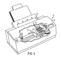
- FIG. 5 is a perspective view of a printer including one or more printheads in accordance with an embodiment of the present teachings.
- FIGS. It should be noted that some details of the FIGS. have been simplified and are drawn to facilitate understanding of the present teachings rather than to maintain strict structural accuracy, detail, and scale.
- the word “printer” encompasses any apparatus that performs a print outputting function for any purpose, such as a digital copier, bookmaking machine, facsimile machine, a multi-function machine, electrostatographic device, etc.
- the word “polymer” encompasses any one of a broad range of carbon-based compounds formed from long-chain molecules including thermoset polyimides, thermoplastics, resins, polycarbonates, epoxies, and related compounds known to the art.
- substrate can encompass a printhead interposer, a printhead ink reservoir, or any printhead surface to which a printing device is attached where the surface has a slot, channel, or orifice for passage for ink through the substrate.
- printing device may be a semiconductor die, a printhead jet stack subassembly, a printhead subassembly, or any printhead structure that includes at least one micro-sized fluidic path, or a plurality of micro-sized fluidic paths, wherein the plurality of fluidic paths are configured for the flow of ink and/or the ejection of ink, for example the ejection of ink through a nozzle or aperture.
- An embodiment of the present teachings may result in a more reliable and higher yield (lower defect) fluid seal between two or more structures in an ink jet printhead.
- the two or more structures can include a printing device such as a semiconductor die, a jet stack subassembly, or other printhead subassembly, and a printhead substrate such as an ink reservoir or a polymer interposer between the ink reservoir and the printing device. While the description below generally describes the embodiments with reference to a semiconductor die as the printing device, it will be understood that an embodiment of the present teachings can include any printing device.
- FIGS. 1-4 are plan views and cross sections of in-process structures which can be formed during an embodiment of the present teachings for physically connecting two or more printhead structures together with a fluid-tight seal.
- FIG. 1 is a plan view depicting a substrate 10 , for example a polymer interposer that may be polyimide, to which an ink reservoir and one or more printing devices can be attached at opposite sides.
- a substrate 10 for example a polymer interposer that may be polyimide, to which an ink reservoir and one or more printing devices can be attached at opposite sides.
- the structures depicted are exemplary for a particular use of the present teachings, but different structures can be connected together in other embodiments of the present teachings.
- FIGS. represent generalized schematic illustrations and that other components may added or existing components may be removed or modified.
- the interposer 10 of FIG. 1 includes an ink channel 12 configured to pass ink from an ink reservoir 48 ( FIG. 4B ) on the opposite side of the interposer 10 .
- the interposer 10 can help align the ink channel 12 of a structure that does not have the appropriate size, location, and geometry of ink channel.
- the ink channel 12 can be defined in part by a narrow section of material 14 along an edge of the interposer 10 .
- FIG. 2 depicts the FIG. 1 interposer 10 after the application of a patterned first adhesive 20 as a first die bonding step (i.e., a first printing device bonding step), which may be a die bonding epoxy.
- the die bonding epoxy 20 may be applied using any sufficient technique, such as pad printing, screen printing, etc.
- the die bonding epoxy 20 may be, for example, a pad-printable, B-stage, thermally conductive adhesive such as part no. EXP2620-50 available from Creative Materials of Ayer, Mass., or another adhesive. B-stage adhesives are well known. As the adhesive 20 may be exposed to ink such as melted solid ink during printing, the material should be chemically resistant to ink and stable at high temperatures.
- the adhesive 20 can have a viscosity of between about 2 pascal-second (Pa ⁇ s) and about 100 Pa ⁇ s, or between about 5 Pa ⁇ s and about 50 Pa ⁇ s, or between about 8 Pa ⁇ s and about 20 Pa ⁇ s. At this viscosity, the die bonding adhesive is sufficiently viscous so that it resists flowing into the ink channel 12 while maintaining its suitability for pad printing or screen printing.
- Pa ⁇ s pascal-second
- the adhesive 20 can have a viscosity of between about 2 pascal-second (Pa ⁇ s) and about 100 Pa ⁇ s, or between about 5 Pa ⁇ s and about 50 Pa ⁇ s, or between about 8 Pa ⁇ s and about 20 Pa ⁇ s.
- a pad printing process for an adhesive is disclosed in application Ser. No. 13/657,095, titled “Liquid Adhesive Application By Contact Printing,” filed Oct. 22, 2012, which is incorporated herein in its entirety.
- a pad printer passes an ink cup over a chemically etched pattern in a stainless steel plate. The motion of the cup functions as doctor blade to leave epoxy within recesses in the steel plate.
- the epoxy can be partially gelled after doctoring, and then a pneumatically operated pad contacts the epoxy pattern, lifts the epoxy away from the steel plate, repositions itself over the interposer 10 , and stamps the interposer 10 leaving a layer of epoxy 20 approximately 5 ⁇ m thick.
- Multiple stamps of the epoxy may be used to build up the thickness, for example to between about 25 ⁇ m and about 50 ⁇ m, or another thickness that is suitable to isolate the path defined by the ink channel 12 .
- the depicted embodiment does not place the adhesive 20 along the narrow section of material 14 . Due to its narrow dimensions, placement of adhesive 20 along this section 14 can be difficult. Misplacement of the adhesive 20 can result in adhesive that partially or completely occludes the ink channel 12 and/or insufficient adhesion of a subsequently attached semiconductor die, jet stack subassembly, or other printing device 30 ( FIG. 3 ) to the interposer 10 which can result in leakage of ink between the printing device 30 and the interposer 10 . Further, misplacement of the printing device 30 itself may result in an insufficient seal between the narrow section of material 14 and the printing device 30 .
- At least one printing device 30 such as a semiconductor (e.g., silicon) die, jet stack subassembly, or other structure that functions as a printing device during printing is aligned with, and attached to, the interposer 10 using the die bonding epoxy 20 as depicted in the plan view of FIG. 3A and the cross section of FIG. 3B .
- a semiconductor die e.g., silicon
- the die bonding epoxy 20 may be cured using a technique appropriate for the adhesive 20 .
- the die bonding epoxy 20 serves to mechanically secure the die 30 to the interposer 10 , and further fluidically seals and isolates the ink channel 12 at a location beneath the die 30 .
- the die 30 or other printing device of FIG. 3 includes a plurality of ink inlets 32 as fluid paths (e.g., ink paths), for example one or more rows of inlets each including 96 or more ink inlets. Each row of ink inlets 32 must align with the ink channel 12 in the interposer 10 . It will be appreciated that while FIG. 3A depicts the relative location of the ink inlets 32 , these features are typically partially etched in die 30 as depicted in FIG. 3B and are not typically visible from the top of the die 30 in the plan view of FIG. 3A . Further, the printing device 30 also typically includes a plurality of ink channels that connect to the ink inlets 32 and route ink across the die 30 to other locations, but the ink channels within the die have not been depicted for simplicity.
- fluid paths e.g., ink paths
- the die bonding epoxy 20 provides a fluid-tight seal between the die 30 and the interposer 10 at the bonded locations depicted in FIGS. 3A and 3B
- a bead of high-viscosity damming encapsulant or adhesive 40 is applied that physically contacts the die 30 and the interposer 10 as depicted in FIGS. 4A and 4B as a second die bonding step.
- the damming adhesive 40 seals the gap at the edge of the die 30 and the upper surface of the interposer 10 between the die 30 and the interposer 10 .
- the damming adhesive 40 may be applied as an unpatterned die bonding adhesive along the perimeter of the die 30 using, for example, a pressurized syringe 42 and needle dispense tip 43 , and then cured using a process appropriate for the adhesive 40 . It will be understood that the various structures of the FIGS., including the syringe 42 depicted in FIG. 4B , are depicted for illustration purposes and are not necessarily to scale.
- the damming adhesive 40 is considered to be an unpatterned adhesive as its shape at the initial contact with the interposer 10 (e.g., part of the adhesive 44 remains in a syringe 42 upon initial contact with the interposer 10 in a syringe-deposition embodiment) is different than its shape at the completion of its application. This is in contrast to the die bonding adhesive 20 , which has its final shape upon initial contact with the interposer 10 .
- the damming adhesive 40 may be Hysol FP4451 available from Henkel Corporation of Rocky Hill, Conn. or another adhesive that has sufficient properties for use as a high-viscosity damming encapsulant.
- the damming adhesive 40 functions to seal the perimeter at the base of each die 30 in the locations of the ink channel 12 .
- the damming adhesive 40 should thus be chemically resistant to ink and stable at high temperatures.
- a higher viscosity material i.e., higher than the viscosity of the die bonding adhesive 20 .
- Such wicking has the potential to plug the ink channel 12 .
- the damming adhesive 40 during application, can have a viscosity of between about 200 Pa ⁇ s and about 3000 Pa ⁇ s, or between about 500 Pa ⁇ s and about 1800 Pa ⁇ s, or between about 1000 Pa ⁇ s and about 1500 Pa ⁇ s.
- the use of a high viscosity adhesive for the damming adhesive 40 and a lower viscosity adhesive for the die bonding epoxy 20 thus includes a two-step die bonding process, where each adhesive bonds a different location of the die 30 .
- the damming adhesive 40 may be applied to overlap the die bonding epoxy 20 at the edges of the die 30 to complete the ink-tight seal.
- ends of the damming adhesive 40 can abut and physically contact edges of the die bonding adhesive 20 .
- the damming adhesive 40 may not physically contact the die bonding adhesive 20 .
- an embodiment of the present teachings can include the use of both a patterned adhesive and a non-patterned adhesive.
- a pad printing process, a screen printing process, or another patterned adhesive application process may be used to apply a patterned adhesive.
- an application of a non-patterned adhesive for example using a pressurized syringe deposition, is sufficient to seal a gap between the printing device and the substrate.
- the narrow section of material 14 is very close to, and partially defines, the ink channel 12 .
- the second adhesive 40 is applied to the narrow section of material 14 using syringe deposition after initial attachment of the die 30 to the substrate, there is little or no concern for adhesive bond line thickness of the second adhesive 40 .
- the die 30 is already partially attached to the substrate 10 upon application of the second adhesive 40 , squeeze-out of the second adhesive 40 into the ink channel 12 is not a concern. Any excess second adhesive 40 remains on the narrow section of material 14 and does not encroach into the ink channel 12 . Further, the edge of the die 30 can be used as a guide for applying the second adhesive 40 .
- a needle 43 of a depositing syringe 42 can be aligned with the edge of the die 30 during deposition of the second adhesive 40 as depicted in FIG. 4B .
- Using the edge of the die or other printing device 30 for alignment during placement of an adhesive 40 onto the substrate 10 not possible in processes where a single adhesive layer is used to attach the entire die to the substrate 10 .
- the edge of the printing device 30 can be used to align the second adhesive 40 with the narrow section of material 14 . This ensures that the second adhesive 40 is properly placed with respect to the printing device 30 and to the narrow section of material 14 .
- first adhesive having a first relatively low viscosity and a first chemical composition
- second adhesive having a second relatively high viscosity (i.e., higher than the viscosity of the first adhesive) and a second chemical composition different than the first chemical composition
- first adhesive having a first relatively low viscosity and a first chemical composition
- second adhesive having a second relatively high viscosity (i.e., higher than the viscosity of the first adhesive) and a second chemical composition different than the first chemical composition
- second relatively high viscosity i.e., higher than the viscosity of the first adhesive
- second chemical composition different than the first chemical composition
- thermoset adhesives used as the die bonding adhesive 20 are relatively inexpensive compared to other assembly and packaging techniques such as gold brazing.
- Thermosets may be cured at relatively lower temperatures which enables adhesive curing of a device that contains PZT actuator material, as the low temperatures required for curing avoids depoling of the PZT actuator array.
- this process may give latitude to designs that would have otherwise been tightly constrained with regard, for example, to the locations available for ink ports.
- using a high viscosity adhesive around the ink channels reduces squeeze-out and occlusions caused by adhesive, and still allows the advantages of a B-stage adhesive to physically attach the die to the substrate such as an ink reservoir or interposer.
- FIG. 4B schematically illustrates an ink reservoir 48 that supplies ink 56 through the ink channel 12 in the interposer 10 and to the ink inlets 32 in the printing device 30 .
- FIG. 5 depicts a printer 50 including a printer housing 52 into which at least one printhead 54 including an embodiment of the present teachings has been installed and that encases the printhead 54 .
- ink 56 is ejected from one or more printheads 54 .
- the printhead 54 is operated in accordance with digital instructions to create a desired image on a print medium 58 such as a paper sheet, plastic, etc.
- the printhead 54 may move back and forth relative to the print medium 58 in a scanning motion to generate the printed image swath by swath.
- the printhead 54 may be held fixed and the print medium 58 moved relative to it, creating an image as wide as the printhead 54 in a single pass.
- the printhead 54 can be narrower than, or as wide as, the print medium 58 .
- the printhead 54 can print to an intermediate surface such as a rotating drum or belt (not depicted for simplicity) for subsequent transfer to a print medium.
- the numerical values as stated for the parameter can take on negative values.
- the example value of range stated as “less than 10” can assume negative values, e.g. ⁇ 1, ⁇ 2, ⁇ 3, ⁇ 10, ⁇ 20, ⁇ 30, etc.
- one or more of the acts depicted herein may be carried out in one or more separate acts and/or phases.
- the terms “including,” “includes,” “having,” “has,” “with,” or variants thereof are used in either the detailed description and the claims, such terms are intended to be inclusive in a manner similar to the term “comprising.”
- the term “at least one of” is used to mean one or more of the listed items can be selected.
- the term “on” used with respect to two materials, one “on” the other means at least some contact between the materials, while “over” means the materials are in proximity, but possibly with one or more additional intervening materials such that contact is possible but not required.
- Terms of relative position as used in this application are defined based on a plane parallel to the conventional plane or working surface of a workpiece, regardless of the orientation of the workpiece.
- the term “horizontal” or “lateral” as used in this application is defined as a plane parallel to the conventional plane or working surface of a workpiece, regardless of the orientation of the workpiece.
- the term “vertical” refers to a direction perpendicular to the horizontal. Terms such as “on,” “side” (as in “sidewall”), “higher,” “lower,” “over,” “top,” and “under” are defined with respect to the conventional plane or working surface being on the top surface of the workpiece, regardless of the orientation of the workpiece.
Abstract
Description
Claims (10)
Priority Applications (2)
| Application Number | Priority Date | Filing Date | Title |
|---|---|---|---|
| US13/759,982 US8740357B1 (en) | 2013-02-05 | 2013-02-05 | Method and structure for sealing fine fluid features in a printing device |
| CN201410027446.3A CN103963469B (en) | 2013-02-05 | 2014-01-21 | Ink jet-print head and ink-jet printer |
Applications Claiming Priority (1)
| Application Number | Priority Date | Filing Date | Title |
|---|---|---|---|
| US13/759,982 US8740357B1 (en) | 2013-02-05 | 2013-02-05 | Method and structure for sealing fine fluid features in a printing device |
Publications (1)
| Publication Number | Publication Date |
|---|---|
| US8740357B1 true US8740357B1 (en) | 2014-06-03 |
Family
ID=50781158
Family Applications (1)
| Application Number | Title | Priority Date | Filing Date |
|---|---|---|---|
| US13/759,982 Active US8740357B1 (en) | 2013-02-05 | 2013-02-05 | Method and structure for sealing fine fluid features in a printing device |
Country Status (2)
| Country | Link |
|---|---|
| US (1) | US8740357B1 (en) |
| CN (1) | CN103963469B (en) |
Citations (17)
| Publication number | Priority date | Publication date | Assignee | Title |
|---|---|---|---|---|
| US6358354B1 (en) * | 2000-07-05 | 2002-03-19 | Lexmark International, Inc. | UV and thermally curable adhesive formulation |
| US20020063757A1 (en) | 1999-07-07 | 2002-05-30 | Torahiko Kanda | Ink jet recording head and method for fabricating same |
| US6502926B2 (en) * | 2001-01-30 | 2003-01-07 | Lexmark International, Inc. | Ink jet semiconductor chip structure |
| US20040085396A1 (en) | 2002-10-30 | 2004-05-06 | Ahne Adam J. | Micro-miniature fluid jetting device |
| US6787049B2 (en) | 1999-03-02 | 2004-09-07 | Hewlett-Packard Development Company, L.P. | Fluid ejection device |
| US6966630B2 (en) | 2001-07-06 | 2005-11-22 | Ricoh Printing Systems, Ltd. | Inkjet head |
| US7073902B2 (en) | 2001-03-30 | 2006-07-11 | L&P Property Management Company | Method and apparatus for ink jet printing |
| US20070165076A1 (en) | 2006-01-19 | 2007-07-19 | 3M Innovative Properties Company | Flexible circuits having ink-resistant covercoats |
| US20080239022A1 (en) | 2007-03-28 | 2008-10-02 | Xerox Corporation | Self aligned port hole opening process for ink jet print heads |
| US20090190968A1 (en) | 2008-01-24 | 2009-07-30 | Xerox Corporation | Direct imaging system with addressable actuators on a development roll |
| US20090315946A1 (en) | 2008-06-05 | 2009-12-24 | Osamu Koseki | Head chip, liquid jet head, and liquid jet device |
| US20100040829A1 (en) | 2008-08-12 | 2010-02-18 | Xerox Corporation | Protective coatings for solid inkjet applications |
| US20100062570A1 (en) | 2008-09-11 | 2010-03-11 | Test Howard Raeburn | Leadframe surface with selective adhesion promoter applied with an offset gravure printing process for improved mold compound and die attach adhesive adhesion |
| US20100149296A1 (en) | 2008-12-17 | 2010-06-17 | Robert Lee Cornell | Uv-curable coatings and methods for applying uv-curable coatings using thermal micro-fluid ejection heads |
| US7922860B2 (en) | 2005-03-18 | 2011-04-12 | Konica Minolta Holdings, Inc. | Manufacturing inkjet head by adhering with epoxy resins and alkyl imidazole |
| US20110141206A1 (en) | 2009-12-16 | 2011-06-16 | Palo Alto Research Center Incorporated | Stacked slice printhead |
| US20110304671A1 (en) | 2010-06-15 | 2011-12-15 | Xerox Corporation | Inkjet printhead with self-clean ability for inkjet printing |
Family Cites Families (2)
| Publication number | Priority date | Publication date | Assignee | Title |
|---|---|---|---|---|
| JPH07304180A (en) * | 1994-05-10 | 1995-11-21 | Seikosha Co Ltd | Manufacture of ink jet head |
| JPH07314671A (en) * | 1994-05-25 | 1995-12-05 | Citizen Watch Co Ltd | Recording head for ink jet recorder |
-
2013
- 2013-02-05 US US13/759,982 patent/US8740357B1/en active Active
-
2014
- 2014-01-21 CN CN201410027446.3A patent/CN103963469B/en active Active
Patent Citations (17)
| Publication number | Priority date | Publication date | Assignee | Title |
|---|---|---|---|---|
| US6787049B2 (en) | 1999-03-02 | 2004-09-07 | Hewlett-Packard Development Company, L.P. | Fluid ejection device |
| US20020063757A1 (en) | 1999-07-07 | 2002-05-30 | Torahiko Kanda | Ink jet recording head and method for fabricating same |
| US6358354B1 (en) * | 2000-07-05 | 2002-03-19 | Lexmark International, Inc. | UV and thermally curable adhesive formulation |
| US6502926B2 (en) * | 2001-01-30 | 2003-01-07 | Lexmark International, Inc. | Ink jet semiconductor chip structure |
| US7073902B2 (en) | 2001-03-30 | 2006-07-11 | L&P Property Management Company | Method and apparatus for ink jet printing |
| US6966630B2 (en) | 2001-07-06 | 2005-11-22 | Ricoh Printing Systems, Ltd. | Inkjet head |
| US20040085396A1 (en) | 2002-10-30 | 2004-05-06 | Ahne Adam J. | Micro-miniature fluid jetting device |
| US7922860B2 (en) | 2005-03-18 | 2011-04-12 | Konica Minolta Holdings, Inc. | Manufacturing inkjet head by adhering with epoxy resins and alkyl imidazole |
| US20070165076A1 (en) | 2006-01-19 | 2007-07-19 | 3M Innovative Properties Company | Flexible circuits having ink-resistant covercoats |
| US20080239022A1 (en) | 2007-03-28 | 2008-10-02 | Xerox Corporation | Self aligned port hole opening process for ink jet print heads |
| US20090190968A1 (en) | 2008-01-24 | 2009-07-30 | Xerox Corporation | Direct imaging system with addressable actuators on a development roll |
| US20090315946A1 (en) | 2008-06-05 | 2009-12-24 | Osamu Koseki | Head chip, liquid jet head, and liquid jet device |
| US20100040829A1 (en) | 2008-08-12 | 2010-02-18 | Xerox Corporation | Protective coatings for solid inkjet applications |
| US20100062570A1 (en) | 2008-09-11 | 2010-03-11 | Test Howard Raeburn | Leadframe surface with selective adhesion promoter applied with an offset gravure printing process for improved mold compound and die attach adhesive adhesion |
| US20100149296A1 (en) | 2008-12-17 | 2010-06-17 | Robert Lee Cornell | Uv-curable coatings and methods for applying uv-curable coatings using thermal micro-fluid ejection heads |
| US20110141206A1 (en) | 2009-12-16 | 2011-06-16 | Palo Alto Research Center Incorporated | Stacked slice printhead |
| US20110304671A1 (en) | 2010-06-15 | 2011-12-15 | Xerox Corporation | Inkjet printhead with self-clean ability for inkjet printing |
Non-Patent Citations (4)
| Title |
|---|
| M.B. Saeed et al., "Effects of Monomer Structure and Imidization Degree on Mechanical Properties and Viscoelastic Behavior of Thermoplastic Polyimide Films", European Polymer Journal 42, 2006, pp. 1844-1854. |
| X. Wen et al., "Liquid Adhesive Application by Contact Printing", U.S. Appl. No. 13/657,095, filed Oct. 22, 2012. |
| Zuo et al., "Multi-Film Adhesive Design for Interfacial Bonding Printhead Structures", U.S. Appl. No. 13/307,231, filed Nov. 30, 2011. |
| Zuo et al., Final Office Action dated Sep. 20, 2013, U.S. Appl. No. 13/307,231, filed Nov. 30, 2011, pp. 1-15. |
Also Published As
| Publication number | Publication date |
|---|---|
| CN103963469A (en) | 2014-08-06 |
| CN103963469B (en) | 2016-12-28 |
Similar Documents
| Publication | Publication Date | Title |
|---|---|---|
| JP6446798B2 (en) | Droplet discharge head and image forming apparatus | |
| US9022528B2 (en) | Liquid ejecting head and liquid ejecting apparatus | |
| US10081161B2 (en) | Electronic device and manufacturing method of electronic device | |
| US9956780B2 (en) | Electronic device, liquid ejecting head, and manufacturing method of electronic device | |
| US9782970B2 (en) | Ink-jet recording head, recording element substrate, method for manufacturing ink-jet recording head, and method for manufacturing recording element substrate | |
| US10207503B2 (en) | MEMS device, liquid ejecting head, liquid ejecting apparatus, and MEMS device manufacturing method | |
| JP6372618B2 (en) | Piezoelectric device, liquid ejecting head, piezoelectric device manufacturing method, and liquid ejecting head manufacturing method | |
| JP2007296790A (en) | Method for manufacturing liquid jetting head, and liquid jetting head | |
| US8740357B1 (en) | Method and structure for sealing fine fluid features in a printing device | |
| US9682549B2 (en) | Electronic device, liquid ejecting head, and method of manufacturing electronic device | |
| US9789688B2 (en) | Electronic device, and method for manufacturing electronic device | |
| US8998380B2 (en) | Liquid ejecting head, liquid ejecting apparatus | |
| JP6403033B2 (en) | Electronic devices | |
| JP6098414B2 (en) | Liquid discharge head, liquid discharge device, and method of manufacturing liquid discharge head | |
| JP6130308B2 (en) | How to make an inkjet printhead | |
| US9073322B1 (en) | Electrostatic device improved membrane bonding | |
| US8944558B2 (en) | Liquid ejection head and liquid ejection apparatus | |
| JP2016157773A (en) | Electronic device and electronic device manufacturing method | |
| US9889629B2 (en) | Electronic device manufacturing method and electronic device | |
| JP2016107551A (en) | Piezoelectric device, liquid spray head, manufacturing method for piezoelectric device and manufacturing method for liquid spray head | |
| JP2008194985A (en) | Manufacturing method of liquid ejection head | |
| JP2011218727A (en) | Inkjet head and method of manufacturing the same | |
| JP2015163437A (en) | Liquid ejection head and liquid ejection device | |
| JP2012218211A (en) | Liquid ejection head, liquid ejecting apparatus, and method of manufacturing liquid ejection head |
Legal Events
| Date | Code | Title | Description |
|---|---|---|---|
| AS | Assignment |
Owner name: XEROX CORPORATION, CONNECTICUT Free format text: ASSIGNMENT OF ASSIGNORS INTEREST;ASSIGNORS:DOLAN, BRYAN R.;CELLURA, MARK A.;NYSTROM, PETER J.;AND OTHERS;REEL/FRAME:029759/0173 Effective date: 20130201 |
|
| FEPP | Fee payment procedure |
Free format text: PAYOR NUMBER ASSIGNED (ORIGINAL EVENT CODE: ASPN); ENTITY STATUS OF PATENT OWNER: LARGE ENTITY |
|
| STCF | Information on status: patent grant |
Free format text: PATENTED CASE |
|
| MAFP | Maintenance fee payment |
Free format text: PAYMENT OF MAINTENANCE FEE, 4TH YEAR, LARGE ENTITY (ORIGINAL EVENT CODE: M1551) Year of fee payment: 4 |
|
| MAFP | Maintenance fee payment |
Free format text: PAYMENT OF MAINTENANCE FEE, 8TH YEAR, LARGE ENTITY (ORIGINAL EVENT CODE: M1552); ENTITY STATUS OF PATENT OWNER: LARGE ENTITY Year of fee payment: 8 |
|
| AS | Assignment |
Owner name: CITIBANK, N.A., AS AGENT, DELAWARE Free format text: SECURITY INTEREST;ASSIGNOR:XEROX CORPORATION;REEL/FRAME:062740/0214 Effective date: 20221107 |
|
| AS | Assignment |
Owner name: XEROX CORPORATION, CONNECTICUT Free format text: RELEASE OF SECURITY INTEREST IN PATENTS AT R/F 062740/0214;ASSIGNOR:CITIBANK, N.A., AS AGENT;REEL/FRAME:063694/0122 Effective date: 20230517 |
|
| AS | Assignment |
Owner name: CITIBANK, N.A., AS COLLATERAL AGENT, NEW YORK Free format text: SECURITY INTEREST;ASSIGNOR:XEROX CORPORATION;REEL/FRAME:064760/0389 Effective date: 20230621 |
|
| AS | Assignment |
Owner name: JEFFERIES FINANCE LLC, AS COLLATERAL AGENT, NEW YORK Free format text: SECURITY INTEREST;ASSIGNOR:XEROX CORPORATION;REEL/FRAME:065628/0019 Effective date: 20231117 |
|
| AS | Assignment |
Owner name: CITIBANK, N.A., AS COLLATERAL AGENT, NEW YORK Free format text: SECURITY INTEREST;ASSIGNOR:XEROX CORPORATION;REEL/FRAME:066741/0001 Effective date: 20240206 |