US8746357B2 - Fine water mist multiple orientation discharge fire extinguisher - Google Patents
Fine water mist multiple orientation discharge fire extinguisher Download PDFInfo
- Publication number
- US8746357B2 US8746357B2 US11/875,494 US87549407A US8746357B2 US 8746357 B2 US8746357 B2 US 8746357B2 US 87549407 A US87549407 A US 87549407A US 8746357 B2 US8746357 B2 US 8746357B2
- Authority
- US
- United States
- Prior art keywords
- liquid
- gas
- suppression
- containment vessel
- carrier gas
- Prior art date
- Legal status (The legal status is an assumption and is not a legal conclusion. Google has not performed a legal analysis and makes no representation as to the accuracy of the status listed.)
- Active, expires
Links
Images


Classifications
-
- A—HUMAN NECESSITIES
- A62—LIFE-SAVING; FIRE-FIGHTING
- A62C—FIRE-FIGHTING
- A62C3/00—Fire prevention, containment or extinguishing specially adapted for particular objects or places
- A62C3/07—Fire prevention, containment or extinguishing specially adapted for particular objects or places in vehicles, e.g. in road vehicles
- A62C3/08—Fire prevention, containment or extinguishing specially adapted for particular objects or places in vehicles, e.g. in road vehicles in aircraft
-
- A—HUMAN NECESSITIES
- A62—LIFE-SAVING; FIRE-FIGHTING
- A62C—FIRE-FIGHTING
- A62C31/00—Delivery of fire-extinguishing material
- A62C31/02—Nozzles specially adapted for fire-extinguishing
-
- A—HUMAN NECESSITIES
- A62—LIFE-SAVING; FIRE-FIGHTING
- A62C—FIRE-FIGHTING
- A62C35/00—Permanently-installed equipment
- A62C35/02—Permanently-installed equipment with containers for delivering the extinguishing substance
- A62C35/023—Permanently-installed equipment with containers for delivering the extinguishing substance the extinguishing material being expelled by compressed gas, taken from storage tanks, or by generating a pressure gas
Definitions
- the invention relates generally to suppression of exothermic reactions and particularly to suppression of fires.
- NSA National Aeronautics and Space Administration
- CO 2 carbon dioxide
- ISS International Space Station
- halon chemical extinguishers on the Space Shuttle.
- TLV threshold limit value
- Halon use in future spacecraft has been taken out of consideration by NASA out of observance of the international protocols against substances that destroy the ozone layer.
- Gaseous agents used in halon fire-fighting systems have been associated with depletion of the ozone layer, and their use is being phased out around the world.
- a timetable for replacement was developed as part of the Montreal Protocol, which has encouraged a significant effort here and abroad to identify replacement agents that are as effective as halons, but do not impact the environment. To date, this effort has focused on near-term substitution of other halocarbon compounds, including halochlorofluorocarbons (HCFCs), halofluorocarbons (HFCs) and perfluorocarbons.
- HCFCs halochlorofluorocarbons
- HFCs halofluorocarbons
- perfluorocarbons perfluorocarbons.
- NASA protocols require de-orbiting of a spacecraft after deployment of a halon extinguisher because the ECLSS systems have no means of scrubbing bromofluorocarbons. Another issue is the loss of fire protection once the halon system has been discharged.
- Fine water mist can suppress fires by attacking all three legs of the “fire triangle”: heat, radiation, and fuel source.
- Water mist can take away heat from the fire as both sensible and latent heat.
- the sensible heat effects of water are as significant as the latent heat.
- the steam produced can then act as an inerting agent, or diluent, to inhibit fire propagation.
- water mist can act to wet surfaces, which reduces the volatilization of solids and thus the amount of fuel present.
- a water aerosol becomes an optically dense medium that prevents the infrared heating of unburned surfaces by burning surfaces. Also, the nitrogen gas used in the generation and propulsion of the fine water mist displaces the oxygen, thereby removing a combustion component from the fire.
- Fine water mists hold considerable promise as fire suppression agents.
- Important design criterion for fine water mist extinguishers include the droplet properties of size and momentum, which are in large part controlled by the atomizer/nozzle design.
- Engineering of fine mist systems for specific applications is needed, because development of fine mist technology is in an early stage.
- the present invention is directed to a suppression system and method using a separation member in a containment vessel to separate a carrier/atomization gas from a suppression liquid.
- a method for suppressing an exothermic reaction includes the steps:
- a suppression system includes:
- the suppression system can be a portable fire extinguisher UDOS (Universal Discharge Orientation System) that can extinguish fires aboard space-craft in low gravity or microgravity environments or in vehicles, even when the vehicle is upside down.
- the suppression system is preferably a water mist system that can operate in microgravity, in any gravitational field, or at any orientation.
- the UDOS can have many desirable features, including a low weight and a totally self-contained and modular design. There commonly is no complex piping to thread through a crowded habitation module and mounting is simplified.
- a perforated flow tube containing multiple holes allows the liquid to enter the tube from anywhere in the contained liquid volume.
- segments of the separation member can be forced against a single opening with the suppression liquid (e.g., water) still remaining in the volume during discharge.
- the suppression liquid e.g., water
- Use of a perforated tube allows water to flow almost anywhere within the bladder and still exit via the perforated tube.
- the separation member separates the water and gas constituents but can still allow the pressure in the gas phase to be successfully transferred to the water/liquid phase to discharge the contents and facilitate the generation of fine water mist droplets. This can remove the gravity requirement of a typical fire extinguisher, which suffers operational problems when discharged on its side.
- the system can exploit the slow pressure decay of the gas phase during discharge to force the flow of water/liquid from the containment vessel and allow the system contents to be depleted effectively in all orientations.
- This type of system can be deployed in aircraft, spacecraft, and other vehicles without concern for system orientation with respect to gravity.
- the system can use a check valve and aspirating venturi to blend the liquid with the propellant/atomization gas.
- the body housing the venturi can be configured to use minimal turns and length of flow path from inlet to outlet. This keeps the gas and liquid phases well-mixed in the flow.
- the generation of fine water mist can be enhanced by the presence of a uniform distribution of small bubbles of gas in a continuous flow of water.
- At least one”, “one or more”, and “and/or” are open-ended expressions that are both conjunctive and disjunctive in operation.
- each of the expressions “at least one of A, B and C”, “at least one of A, B, or C”, “one or more of A, B, and C”, “one or more of A, B, or C” and “A, B, and/or C” means A alone, B alone, C alone, A and B together, A and C together, B and C together, or A, B and C together.
- FIG. 1 is an extinguisher according to a first embodiment of the present invention
- FIG. 2 is a partial cross-sectional view of an extinguisher according to a second embodiment of the present invention
- FIG. 3 is a perspective cut-away view of a valve assembly of a third embodiment
- FIG. 4 is a disassembled view of the valve subassembly of the third embodiment
- FIG. 5 is a cross-sectional view of the valve subassembly of the third embodiment taken along cut line 5 - 5 of FIG. 3 ;
- FIGS. 6A and B are side views of the nozzle assembly of the third embodiment
- FIGS. 7A and B are disassembled views of the nozzle assembly of the third embodiment
- FIG. 8 is a cross-sectional view of a section of the flow path of the nozzle assembly of the third embodiment
- FIG. 9 is a cross-sectional view of a nozzle configured for use with the nozzle assembly of the third embodiment.
- FIG. 10 depicts an extinguisher according to a fourth embodiment of the present invention.
- FIG. 11 is a view of an experimental apparatus according to an embodiment of the invention.
- FIG. 12 is a plot of Sauter Mean Diameter (vertical axis) against spray cross section (horizontal axis);
- FIG. 13 is a plot of droplet velocity (vertical axis) against spray cross section (horizontal axis);
- FIG. 14 is a plot of volumetric flux (vertical axis) against spray cross section (horizontal axis).
- FIG. 1 depicts an extinguisher 100 according to a first embodiment.
- the extinguisher 100 includes a containment vessel 104 , first and second valves 108 and 112 , respectively, first and second flexible hoses 116 and 120 , pressure control 122 (optional) (which controls the liquid pressure in the second hose 120 ), and a hand-held nozzle assembly 124 .
- the containment vessel 104 is rigid and pressure resistant and includes a movable (rigid) piston 128 positioned between upper and lower portions 104 a and b of the vessel 104 .
- the upper portion 104 a of the vessel includes a carrier gas while the lower portion 104 b includes a suppression liquid; therefore, the piston spatially defines the liquid/gas interface.
- the first and second valves 108 and 112 are closed when the extinguisher is not in operation and opened when in operation.
- the pressure of the gas and gravity cause the piston to move downwardly, expelling liquid through the hose 120 .
- the gas is discharged through the hose 116 at a rate low enough to maintain a discharge pressure against the liquid.
- the carrier gas and suppression liquid are maintained in isolation while flowing through their respective hoses 116 and 120 .
- the gas and liquid reach the nozzle assembly 124 , they are mixed together to produce atomized droplets of the liquid dispersed in the carrier gas.
- the atomized liquid is then discharged from the nozzle assembly 124 at a selected velocity in a cone-shaped pattern 132 .
- the carrier gas can be any suitable gas that is inert relative to the suppression liquid and substantially immiscible in the liquid under the conditions of the nozzle assembly.
- suitable carrier gases include nitrogen, carbon dioxide, air, helium, argon, carbon monoxide, and mixtures thereof.
- the carrier gas can be pre-pressured in the vessel 104 or generated rapidly during operation of the extinguisher.
- the carrier gas is typically stored at a pressure ranging from about 100 to about 2500 psi and even more typically from about 300 to about 1200 psi.
- the carrier gas is generated by combustion of a solid or liquid propellant positioned in the upper half 104 a of the vessel 104 .
- the propellant can be any suitable material, the propellant is preferably selected from the group consisting of lead azide, sodium azide, and mixtures thereof.
- the suppression liquid can be any liquid having a heat of vaporization sufficient to absorb the heat as it is generated by the exothermic reaction (e.g., fire, deflagration, or detonation) to be suppressed, a sufficient boiling point to remain in the liquid phase until vaporization by heat absorbtion, and a surface tension sufficient to form atomized liquid droplets.
- the liquid preferably has a heat of vaporization of at least about 500 cal/g and more preferably at least about 800 cal/g, a boiling point that is no less than about 50 degrees Celsius, more preferably no less than about 80 degrees Celsius, and even more preferably no less than about 90 degrees Celsius, and a surface tension of no more than about 0.06 lbs/ft.
- a particularly preferred suppression liquid is water. Water offers the added advantages of being cheap, widely available, environmentally acceptable, and nontoxic.
- the liquid can include additives to enhance the ability of the liquid droplets to suppress the exothermic reaction, such as free radical interceptors.
- a preferred free radical interceptor is an alkali metal salt, including potassium bicarbonate, potassium carbonate, sodium bicarbonate, sodium carbonate, and mixtures thereof.
- the free radical interceptor should have a concentration in the liquid ranging from about 1% up to saturation.
- the liquid can include additives to decrease the freezing point of the liquid for applications at low temperatures.
- the freezing point of water is about 0 degrees Celsius, which is above the system temperature in many applications.
- the liquid can include such freezing-point depressants as glycerine, propylene glycol, diethylene glycol, ethylene glycol, calcium chloride, and mixtures thereof.
- the liquid can include other additives to alter the surface tension of the liquid droplets.
- wetting agents are effective because they decrease the surface tension of the liquid, resulting in the generation of smaller droplets and thus increasing the amount of free surface available for heat absorption.
- Suitable wetting agents include surfactants.
- the liquid can include additives to decrease friction loss in the hoses and nozzle assembly.
- Linear polymers polymers that are a single, straight-line chemical chain with no branches
- Poly(ethylene oxide) is an effective polymer for reducing turbulent frictional losses in the liquid.
- the nozzle assembly 124 includes a liquid-gas mixing device and an atomization device.
- the devices can be similar to the liquid atomizing device of U.S. Pat. No. 5,495,893 (which is incorporated herein by this reference), which uses supersonic and sonic fluid velocities to produce a shock wave that decreases the size of the droplets.
- the devices can be any other devices suitable for mixing and atomization.
- the droplet sizes output by the nozzle assembly 124 are small enough to vaporize rapidly in response to heat absorption with sufficient mass to be distributed throughout a defined area.
- a variable to express the size distribution of the liquid droplets is the Sauter Mean Diameter (SMD).
- the SMD is the total volume of the liquid droplets divided by their total surface area.
- the SMD of the liquid droplets is preferably no more than about 150, more preferably no more than about 50, and even more preferably no more than about 30 microns.
- the surface area of the droplets in the defined area is a function of the size distribution of the liquid droplets and the concentration of the liquid droplets in the defined area at a selected point in time.
- the peak concentration of liquid droplets in the defined area preferably ranges from about 1.5 gal/1,000 ft 3 to about 20 gal/1,000 ft 3 , more preferably from about 2 gal/1,000 ft 3 to about 15 gal/1,000 ft 3 , and even more preferably from about 4 gal/1,000 ft 3 to about 10 gal/1,000 ft 3 .
- the total surface area per unit volume of the liquid droplets in the defined area at the peak liquid droplet concentration is preferably at least about 75 m 2 /m 3 , more preferably at least about 100 m 2 /m 3 , and even more preferably at least about 150 m 2 /m 3 .
- the piston 128 is replaced by a stationary, flexible membrane (not shown).
- the membrane can be an elastic material, such as an elastomer, and may or may not be permeable to the gas.
- the membrane is, however, impermeable to the liquid.
- the membrane is stationary in that its circumference is preferably immovably fixed to the interior surface of the vessel 104 .
- the central portion of the membrane is able to stretch (much like an inflated balloon), in response to gas pressure, to extend substantially the entire length of the lower portion 104 b of the vessel 104 to expel the liquid.
- the gas can, over time, migrate through the membrane until a saturated concentration of gas is in the liquid.
- the liquid flows out of the tank and the pressure drops, the dissolved gas molecules will rapidly enter the gas phase from the liquid phase, thereby facilitating liquid atomization.
- the dissolved gas molecules nucleate as small bubbles distributed substantially uniformly in the liquid phase and the bubbles rapidly expand to provide an additional mechanism for generating fine droplets, thereby enhancing droplet generation by the dispersed gas bubbles in the two-phase mixture. This effect is known as effervescence.
- An emulsifying aid such as a surfactant or cosolvent, may be added to the liquid to increase the gas molecule solubility up to about 10 wt. %.
- FIG. 2 An extinguisher according to a second embodiment is shown in FIG. 2 .
- the extinguisher 200 includes a nozzle assembly 204 and a containment vessel assembly 208 .
- the vessel assembly 208 includes a containment vessel 210 , a perforated flow tube 212 , and an elastomeric membrane or bladder 216 surrounding and enclosing fully the flow tube 212 .
- the membrane 216 divides the inner volume of the vessel 210 into a first (inner) region 220 containing the suppression liquid and a second (outer) region 224 containing the carrier gas.
- the vessel assembly 208 can include a piston valve 230 to actuate liquid and gas flow through the upper portion of the tube 212 , and the nozzle assembly a mixing and atomization device (not shown) in communication with the tube 212 and located at the top of the tank.
- the piston valve is actuated by movement of one or both of the handles 234 and 238 .
- the bladder can be any elastic and/or elastomeric material.
- the bladder has a durometer between about 75 Shore 00 to about 20 Shore 00.
- Preferred bladder materials include silicone, latex, and ultra-soft TygonTM, with latex being preferred.
- Perforations of the tube 212 along substantially the entire length and periphery of the tube provide for uniform and undisturbed liquid flow from the bladder and into the tube.
- the percentage of the surface area of the portion of the tube 212 positioned in the bladder 216 that is occupied by perforations is preferably at least about 5% and even more preferably ranges from about 10 to about 30%.
- FIGS. 3-7B show an extinguisher according to a third embodiment.
- the vessel assembly 208 is the same as that for the second embodiment.
- the extinguisher of this embodiment includes the vessel assembly 208 and a nozzle assembly 300 attached to the vessel 210 .
- the nozzle assembly 300 includes a handle subassembly 600 and a valve subassembly 608 .
- a nozzle 736 such as the nozzle 604 , of FIG. 2 may be included depending on the application.
- the handle subassembly 600 includes upper and lower handles 612 and 616 connected to a bracket 620 .
- the bracket 620 is, in turn, connected to the valve subassembly 608 .
- the upper handle 612 is movably engaged with the bracket 620 and includes a bearing member 624 that engages a manual release valve 628 of the valve subassembly 608 , when the handle is moved towards the lower (stationary) handle 616 .
- the valve subassembly 608 includes a burst or pressure relief disk 700 (that releases gas pressure when gas pressure in the vessel 208 rises above a determined threshold), a body 704 , water and gas fill valve ports 708 and 712 , a pressure gauge 716 , manual release valve 628 , check valve 720 , plug 724 , venturi 728 , and threaded end 732 to threadably engage the vessel 208 .
- the body 704 comprises first, second, third, fourth, fifth, and sixth interconnecting passageways 400 , 404 , 408 , 412 , 450 , and 454 .
- the first passageway 400 receives the release valve 628 and extends longitudinally through the body 704 .
- a smaller diameter segment 424 receives the smaller diameter segment 420 of the release valve 628
- the distal portions 426 and 428 receive the distal portion 432 of the valve 628 .
- the transition 502 between the portions 424 and 426 is gradual such that ports 500 a - d (one of which is not shown) in the release valve portion 420 communicate with an annulus area 504 positioned between the exterior of the valve portion 420 and the interior of the passageway segment 426 .
- the ports 500 a - d are in communication with a conduit 508 in the interior of the valve portion 420 .
- the conduit 508 does not pass longitudinally through the valve 628 .
- the conduit 508 is in communication with the smaller diameter segment 416 of the first passageway 400 .
- An orifice plate 530 is positioned in the conduit 508 to provide a restricted flow as discussed in detail below.
- the proximal end of the first passageway 400 progressively steps into portions of increasing larger diameters 532 and 536 .
- the second passageway 404 intersects the third passageway 408 .
- the second passageway 404 receives the venturi 728 , which is in turn connected to the flow tube 212 .
- the venturi is located in the body, preferably such that there are minimal turns and length to the flow path from inlet to outlet.
- the venturi 728 includes a plurality of tubes 550 a - d (not shown is tube 550 d ) positioned equidistantly around the circumference of the venturi 728 .
- the tubes are in communication with an outer annulus 562 between the inner surface of the second passageway and the outer surface 558 of the venturi and with an inner passageway 554 passing longitudinally through the venturi 728 .
- Both ends of the inner passageway 554 have tapered configurations to form a constricted throat between them.
- the throat when passing the suppression liquid, causes a reduction in pressure.
- the reduction in pressure draws gas through the tubes into the suppression liquid and forms a dispersion of the gas bubbles in the flowing liquid.
- the lower end of the venturi includes an “O” ring to prevent liquid and gas discharge from around the larger diameter, lower end 730 of the venturi.
- the third passageway 408 communicates with the second and fourth passageways and includes a plug 724 and check valve 720 .
- the passageway 408 has a larger diameter than the check valve 720 to define an annulus 570 therebetween.
- the flow passage 574 through the check valve is in communication with the annulus 570 and annulus 562 .
- the check valve 720 includes a movable member (not shown) that, when closed, blocks flow in either direction along the flow passage 574 and, when opened, permits flow in either direction along the flow passage 574 .
- the spring pressure for the movable member of the check valve is very light, preferably no more than about 1 psi, since the primary function of the check valve is to inhibit backflow of the liquid to the gas reservoir section of the vessel.
- a preferred check valve 720 is a 10-32 THD or Barb —CKV manufactured by Beswick Engineering.
- the fourth passageway 412 is in fluid communication with the gas in the vessel 208 and the third passageway 408 .
- the pressurized gas in the annulus 570 exerts a pressure against the movable check valve member that is opposed by an equal and opposite pressure exerted by the liquid in the bladder 216 .
- the check valve is in the closed position.
- the fifth and sixth passageways 450 and 454 receive, respectively, the gas fill port 712 and water fill port 708 .
- the fifth passageway 450 is in fluid communication with the fourth passageway 412
- the sixth passageway 454 is in fluid communication with the second passageway 404 .
- Each of the ports includes a check valve (not shown) that is closed except when a pressurized fluid flow is inputted into the port.
- the extinguisher is thus filled by first filling, via the port 708 , the bladder with a predetermined volume of water.
- the filling procedure is completed by subsequently filling with gas the area of the vessel outside of the bladder until a predetermined pressure is realized.
- the pressure gauge 716 provides the pressure reading in the vessel.
- the pressure gauge is in fluid communication with the fourth passageway 412 (not shown).
- FIG. 8 depicts an alternative configuration of the first passageway.
- the cross-section is taken along the longitudinal axis of the first passageway 400 .
- the orifice plate 530 is positioned in the conduit 528 of the release valve 628 . Downstream of the plate 530 is a nozzle housing 800 and nozzle plate 804 .
- the nozzle plate 804 comprises a number of flow passages 808 a - c extending through the plate 804 .
- the diameters of the flow passages 808 a - c are the same and smaller than the diameter “D A ” of the aperture in the orifice plate 530 .
- D A ranges from about 10 to about 100% of the diameter D C of the conduit 528 .
- D A preferably ranges from about 0.01 to about 0.25 inches, while D C ranges from about 0.25 to about 0.50 inches.
- the area of the aperture preferably ranges from about 90 to about 110% of the cumulative area of the passages through the nozzle plate.
- FIG. 9 depicts another configuration of an integral nozzle plate and housing that is mounted in the outlet of the first passageway.
- the nozzle plate 900 includes a number of flow passages 904 a - e .
- the interior surface 908 of the housing 912 is arcuate to provide a smoother, less turbulent flow path.
- the nozzle plate 900 may include any number of passages 904 depending on the application.
- the ports 500 a - d move into the annulus 504 .
- This displacement into the annulus 504 effectively releases pressure on the liquid and gas simultaneously with the gas pressure providing the motive force via the bladder to cause the liquid to flow from the vessel.
- the gas and liquid constituents can be mixed either at the nozzle or in the liquid and gas transfer conduits from the bladder to the nozzle.
- the liquid under pressure from the gas outside of the bladder 216 , flows (as shown by flow path arrow 580 ) into and through the venturi 728 .
- the static pressure of the liquid decreases as the liquid moves through the venturi throat.
- the reduced liquid pressure at the throat of the venturi causes a pressure differential across the aspirating tubes of the venturi, which displaces the moveable closure member of the check valve (not shown) and pulls the gas through the check valve and into the discharge.
- the liquid pressure at the throat is less than the pressure of the gas in the annulus 570 , thereby causing the check valve closure member to move to the open position and gas to flow into the annulus 562 (as shown by flow path arrow 584 ) and into and through the aspirating tubes 550 a - d (as shown by flow path arrow 588 ).
- the gas and liquid will thereby be mixed at the throat to form gas bubbles (the discontinuous phase) dispersed in the liquid (the continuous phase).
- discontinuous phase refers to the phase constituting at least about 75% by volume of the fluid.
- the size of the carrier gas bubbles is related inversely to the velocity of the liquid past the tubes 550 a - d and directly related to the diameters of the tubes.
- the velocity of the liquid shears carrier gas bubbles from the tubes, with the shear forces being increased at higher velocities.
- the stored pressure of the gas and throat diameter are selected to provide a velocity of the liquid through the throat of at least about 50 ft/sec and even more preferably ranging from about 50 to about 300 ft/sec.
- the stored pressure of the gas preferably is at least about 150 psi and even more preferably ranges from about 300 to about 1200 psi, while the throat has an interior diameter of no more than about 0.2 inches and even more preferably ranging from about 0.08 to about 0.2 inches.
- the diameter of each tube 550 preferably ranges from about 0.02 to about 0.05 inches.
- the mass ratio of the gas to the liquid is typically no more than about 0.05 to about 0.3 and even more preferably ranges from about 0.08 to about 0.20.
- the fluid mixture flows into the annulus 504 surrounding the proximal end of the release valve.
- the cross-sectional area of the annulus 504 normal to the direction of flow is more than the cross-sectional area normal to flow of the outlet passage between the annulus 504 and the venturi, the liquid phase remains the continuous phase while the gas phase remains the discontinuous phase.
- the fluid at the venturi outlet and in the annulus 504 is preferably from about 20 to about 70% by volume carrier gas.
- Each of the ports 500 a - d typically have a diameter ranging from about 10 to about 60% of the diameter D C , or, in absolute terms, from about 0.01 to about 0.2 inches. Because the cross-sectional area of each port normal to the direction of fluid flow is less than the cross-sectional area normal to liquid flow at any other upstream location (except in some cases at the throat of the venturi), the ports cause the liquid droplets to accelerate and have a higher velocity in the conduit 528 than in the annulus 504 . This velocity is commonly no more than about 1,000 ft/sec and no less than about 100 ft/sec.
- the gas-containing liquid flows through the orifice plate 530 as shown in FIG. 8 .
- the liquid becomes the discontinuous phase, and the gas the continuous phase.
- the increased flow area downstream of the orifice plate 530 causes the carrier gas to expand, and the liquid to form dispersed droplets in the gas.
- the fluid at the venturi outlet is preferably from about 20 to about 70% by volume carrier gas, and the fluid immediately downstream of the orifice plate is preferably from about 50 to about 95% by volume carrier gas. Due to the restricted size of the diameter DA, the fluid reaches the maximum velocity at the aperture.
- the maximum velocity is preferably at least a supersonic velocity.
- a sonic velocity is about 1100 ft/sec in a neat gas (or the speed of sound); sonic velocity can be considerably lower in a two-phase flow mixture.
- a supersonic velocity is greater than a sonic velocity.
- the pressure at the aperture preferably ranges from about 20 psig to about 250 psig.
- the maximum fluid pressure in the first passageway downstream of the orifice plate is no more than about 53% of the fluid pressure at the aperture.
- the cross-sectional area of the passageway normal to the direction of flow progressively increases, with the passageway segment 416 having a larger diameter than the diameter D C , the passageway segment 532 a larger diameter than the passageway segment 416 , and the passageway segment 536 a larger diameter than the passageway segment 532 .
- the droplet velocity will progressively decrease.
- the deceleration of the droplets from a supersonic velocity to a sonic velocity decreases the size of the droplets, as a result of the pressure discontinuity from the resulting shock wave.
- the liquid droplets upstream of the shock wave have larger average, mean, and median sizes than the liquid droplets downstream of the shock wave.
- the distance from the aperture to the first passageway outlet should be sufficient to enable the shock wave to occur in the first passageway upstream of the outlet.
- the distance from the aperture to the passageway outlet is at least twice the distance from the aperture to the point of formation of the shock wave.
- the decreased liquid droplet size is believed to result from the liquid droplets having a Weber number that is no more than about 1.2. It is generally believed that the liquid droplets downstream of the shock wave have an average size that is no more than about 50% of the average size of the droplets upstream of the shock wave.
- the liquid droplets upstream of the shock wave preferably have an SMD of no more than about 160 microns and the liquid droplets downstream of the shock wave an SMD of no more than about 80 microns.
- the liquid droplets outputted from the first passageway preferably have a velocity of at least about 200 ft/sec.
- the fluid next passes through the passages 808 in the nozzle plate 804 to realize further reduction in the droplet size as shown in FIG. 8 .
- the liquid 850 contains carrier gas bubbles 854 .
- the liquid 850 forms droplets 858 while the gas 862 expands to form the continuous phase.
- the liquid droplets must be rapidly dispersed in the area of the reaction.
- the injection rate and velocity of the liquid droplets exiting the extinguisher can be important variables to the ability of the extinguisher to extinguish the reaction.
- the liquid droplet injection rate per unit volume of the reaction area preferably is at least about 1.5 l/sec/m 3 , more preferably at least about 3 l/sec/m 3 , and most preferably at least about 5 l/sec/m 3 . In most applications, the liquid droplet injection rate will preferably range from about 0.5 to about 10 l/min.
- the velocity of the liquid droplets exiting the first passageway outlet preferably ranges from about 100 ft/sec to about 500 ft/sec and more preferably from about 150 ft/sec to 300 ft/sec.
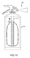
- FIG. 10 Another embodiment of the extinguisher is shown in FIG. 10 .
- the extinguisher 1000 differs from the extinguishers of the other embodiments in that the venturi 1004 and check valve 1008 are positioned inside of, rather than outside of, the containment vessel 210 .
- the check valve opens due to the resulting pressure differential across it, and gas flows into the aspirating ports of the venturi 1004 as noted above.
- the second concept shown in FIG. 11 used a bladder 1100 to separate the gas and liquid phases in the single storage tank 1104 .
- This design employed a bladder.
- the bladder was fitted over the perforated flow pipe and inserted into the vessel.
- the bladder was filled with water while inside the tank, and sealed with a valve.
- the carrier gas was then filled through a second port after its separate discharge valve had been seated.
- release of both water and carrier gas was controlled by a single mechanism that simultaneously operated both valves. Mixing of water and gas occurred downstream of the valves and upstream of the discharge nozzle. Two pneumatically actuated quarter turn ball valves were used.
- Bladder materials evaluated were permeable to CO 2 gas so that CO 2 could dissolve into the liquid water, generating equilibrium with the gas phase in the single tank 1104 .
- the decision to specify nitrogen as the preferred carrier gas allowed the consideration of a wider range of bladder materials.
- a concept nozzle design, similar to that of FIG. 9 (hereinafter ADA# 1 ), to generate a lower-momentum flow of fine water mist was fabricated and evaluated.
- Two factors for fine water mist to extinguish fires in confined and cluttered spaces appear to be 1) droplet size distribution where most of the water mass is contained in droplets less than about 30 microns in diameter, which have a high surface area for rapid evaporation, and 2) minimal momentum of the droplets so that the mist can move easily around barriers in a cluttered environment to get to a well-obstructed fire. Having one of these properties without the other reduces the ability of the fine water mist to extinguish a fire in a confined space. Because decreasing the momentum can reduce the flow or create a non-uniform flow, an ideal discharge nozzle design will offer high flows combined with minimal spray momentum.
- the nozzle design that had a uniform discharge with small droplet size and minimal momentum was coupled to the system of FIG. 11 .
- Many tests were run to optimize the gas-to-liquid ratio (G/L) as well as the flow rates between the tank and nozzles.
- the preferred configuration was a G/L of ⁇ 0.15 with a 0.1′′ diameter orifice restriction between the tank and nozzles. This configuration along with the valve determined from earlier tests gave a uniform discharge of nitrogen and water for 40-45 seconds.
- volume one is a 205-in 3 vessel while the second is 408 in 3 ; these are standard pressure vessels for commercial 5 and 101 b carbon dioxide fire extinguishers.
- the 5 lb vessel was later removed from further testing because the discharge times were extremely small 10-25 seconds depending upon the nozzle used.
- the pan that used to hold the fire is 18′′ wide, 4.5′′ deep, and has a 1.5′′ platform around the edge. A hole was drilled at the base of the pan to allow excess water to drain from the pan. Along the edge of the pan two thermocouples were placed to aid in determining if the fire is extinguished.
- the oxygen gas was pumped through an oxygen service regulator to a flow meter, which is set to 20 scfh. Once through the regulator, an electrically actuated oxygen service ASCO solenoid valve with 1 ⁇ 2′′ connections is used to allow oxygen flow to the fire pan. All of the plumbing is 1 ⁇ 4′′ tube except the ball valve and oxygen aspiration system.
- the oxygen then enters a dispersion device.
- the dispersion device is a 1′′ tube perforated with holes. 0.5 lbs of rags are bundled around and on top of the tube to fuel the fire. The tube is capped at the end opposite of the 1 ⁇ 4′′ tube inlet. Two thermocouples were placed above the fire to monitor fire intensity throughout testing.
- the igniter is a piece of nichrome wire crimped onto a length of two-strand wire. One igniter is consumed during each fire test. The igniter is powered by 120 V activated by a mechanical relay with a 25 amp fuse to prevent blowing the main circuit. It is operated on a separate circuit. The relay switch is 1 second in duration. During the fire tests oxygen is allowed to flow for 10 sec. before the igniter is activated. The target fire is ignited and allowed to build to a specified intensity as measured by the thermocouples.
- the fine water mist fire extinguisher is filled with carrier gas and water at a predetermined mass ratio (typically 0.15 parts carrier gas to one part water), which has been shown in earlier tests to be the optimal mix for a fine water mist fire suppression nozzle. In all of these tests the fires were successfully extinguished.
- a predetermined mass ratio typically 0.15 parts carrier gas to one part water
- Table 1 shows that the carbon dioxide propellant was nominally quicker to extinguish the test fires in all tests.
- the tests were run at a starting pressure of 850 psi in the single storage container, which represents the condition where the CO 2 propellant will be present in the storage tank in both the gas and liquid phases
- FIG. 11 The system of FIG. 11 was deployed inverted to show that the system was capable of extinguishing test fires in other orientations than upright. During this test the system extinguished the fire in 17 seconds, and bladder system showed no failure. The inverted extinguisher put out the test fire quicker than the right-side-up system. Both configurations showed good fine mist generation and dispersion.
- the fine water mists generated by several candidate nozzles were characterized in a configuration similar to that of FIGS. 3-8 .
- the mist was characterized by measuring droplet size and velocity distributions using a phase Doppler particle analyzer. This instrument makes local measurements in a discharge spray in a volume of a few mm 3 .
- the results showed that one nozzle (ADA# 1 ) exhibited lower momentum and similar droplet size distributions compared to the commercially available nozzles.
- Sauter mean diameters were similar, indicating that the droplet specific surface area (surface area per unit volume) generated by the different nozzles was comparable.
- This nozzle data showed a notably higher Dv90 diameter, implying that there is a “tail” of larger-diameter droplets generated in the ADA nozzle.
- FIG. 12 presents the droplet size distribution as a function of distance along the spray center line
- FIG. 13 the droplet velocity also as a function of distance along the spray center line.
- the ADA# 1 nozzle showed a spray profile with a greater cone angle (faster expansion) than the other nozzles; this is indicated in sampling locations that are spaced at twice the interval of the other nozzles.
- the velocity profile for the ADA# 1 nozzle is also seen to be significantly lower than the other nozzles. This is attributed to the larger discharge cross-sectional area of the ADA# 1 nozzle, which should improve the effectiveness of the fine water mist in extinguishing fires in a confined space.
- the design objective is to have both the smaller droplets and lower momentum, so that the mist flows like a gas around obstacles to fill the available space, akin to a gaseous fire suppression agent.
- an even smaller droplet size distribution than that measured in these tests is preferred.
- volumetric flux in the nozzles is shown in the center graph of FIG. 14 as a function of measurement position along a horizontal axis.
- the ADA# 1 nozzle spray pattern appears to be a full cone indicated by flux measurements that are relatively uniform through the central part of the cross section.
- the other nozzles have a hollow cone profile indicated by a substantial drop in flux through the center of the horizontal axis of measurement.
- the bladder is not elastic but a non-elastic material that folds to foster uniform compaction of the contained volume inside the vessel during discharge.
- a non-elastic material that folds to foster uniform compaction of the contained volume inside the vessel during discharge.
- Such a material does not stretch when the system is full of water and thereby avoids the elastic stress which may tear an elastic bladder, particularly where significant acceleration and deceleration occurs.
- the extinguisher can switch between three modes of operation. These modes are inactive, active low momentum and active high momentum.
- the output droplet size ranges from about 10 to about 50 microns and velocity from about 10 to about 100 m/s.
- the output droplet size ranges from about 30 to about 80 microns and velocity from about 30 to about 200 m/s.
- the low momentum mode for example, can be used to extinguish fires in confined or small enclosed areas, while the high momentum mode can be used to extinguish fires in unconfined or large enclosed areas.
- the switch between the low and high momentum modes can be effected, for example, using a variable pressure control to control the fluid pressure in the extinguisher.
- the present invention in various embodiments, includes components, methods, processes, systems and/or apparatus substantially as depicted and described herein, including various embodiments, subcombinations, and subsets thereof. Those of skill in the art will understand how to make and use the present invention after understanding the present disclosure.
- the present invention in various embodiments, includes providing devices and processes in the absence of items not depicted and/or described herein or in various embodiments hereof, including in the absence of such items as may have been used in previous devices or processes, e.g., for improving performance, achieving ease and ⁇ or reducing cost of implementation.
Abstract
Description
| TABLE 1 |
| Extinguishment times for carbon dioxide |
| and nitrogen propellant systems. |
| time to extinguish | |||
| Propellant | (seconds) | ||
| Nitrogen | 35 | ||
| Nitrogen | 34 | ||
| carbon dioxide | 27 | ||
| carbon dioxide | 21 | ||
Claims (37)
Priority Applications (1)
| Application Number | Priority Date | Filing Date | Title |
|---|---|---|---|
| US11/875,494 US8746357B2 (en) | 2006-10-20 | 2007-10-19 | Fine water mist multiple orientation discharge fire extinguisher |
Applications Claiming Priority (3)
| Application Number | Priority Date | Filing Date | Title |
|---|---|---|---|
| US86238306P | 2006-10-20 | 2006-10-20 | |
| US88751807P | 2007-01-31 | 2007-01-31 | |
| US11/875,494 US8746357B2 (en) | 2006-10-20 | 2007-10-19 | Fine water mist multiple orientation discharge fire extinguisher |
Publications (2)
| Publication Number | Publication Date |
|---|---|
| US20080128145A1 US20080128145A1 (en) | 2008-06-05 |
| US8746357B2 true US8746357B2 (en) | 2014-06-10 |
Family
ID=39690659
Family Applications (1)
| Application Number | Title | Priority Date | Filing Date |
|---|---|---|---|
| US11/875,494 Active 2029-01-10 US8746357B2 (en) | 2006-10-20 | 2007-10-19 | Fine water mist multiple orientation discharge fire extinguisher |
Country Status (2)
| Country | Link |
|---|---|
| US (1) | US8746357B2 (en) |
| WO (1) | WO2008100348A2 (en) |
Cited By (16)
| Publication number | Priority date | Publication date | Assignee | Title |
|---|---|---|---|---|
| US10260232B1 (en) | 2017-12-02 | 2019-04-16 | M-Fire Supression, Inc. | Methods of designing and constructing Class-A fire-protected multi-story wood-framed buildings |
| US10290004B1 (en) | 2017-12-02 | 2019-05-14 | M-Fire Suppression, Inc. | Supply chain management system for supplying clean fire inhibiting chemical (CFIC) totes to a network of wood-treating lumber and prefabrication panel factories and wood-framed building construction job sites |
| US10311444B1 (en) | 2017-12-02 | 2019-06-04 | M-Fire Suppression, Inc. | Method of providing class-A fire-protection to wood-framed buildings using on-site spraying of clean fire inhibiting chemical liquid on exposed interior wood surfaces of the wood-framed buildings, and mobile computing systems for uploading fire-protection certifications and status information to a central database and remote access thereof by firefighters on job site locations during fire outbreaks on construction sites |
| US10332222B1 (en) | 2017-12-02 | 2019-06-25 | M-Fire Supression, Inc. | Just-in-time factory methods, system and network for prefabricating class-A fire-protected wood-framed buildings and components used to construct the same |
| US10430757B2 (en) | 2017-12-02 | 2019-10-01 | N-Fire Suppression, Inc. | Mass timber building factory system for producing prefabricated class-A fire-protected mass timber building components for use in constructing prefabricated class-A fire-protected mass timber buildings |
| US10653904B2 (en) | 2017-12-02 | 2020-05-19 | M-Fire Holdings, Llc | Methods of suppressing wild fires raging across regions of land in the direction of prevailing winds by forming anti-fire (AF) chemical fire-breaking systems using environmentally clean anti-fire (AF) liquid spray applied using GPS-tracking techniques |
| US10695597B2 (en) | 2017-12-02 | 2020-06-30 | M-Fire Holdings Llc | Method of and apparatus for applying fire and smoke inhibiting compositions on ground surfaces before the incidence of wild-fires, and also thereafter, upon smoldering ambers and ashes to reduce smoke and suppress fire re-ignition |
| US10814150B2 (en) | 2017-12-02 | 2020-10-27 | M-Fire Holdings Llc | Methods of and system networks for wireless management of GPS-tracked spraying systems deployed to spray property and ground surfaces with environmentally-clean wildfire inhibitor to protect and defend against wildfires |
| WO2022056164A1 (en) * | 2020-09-10 | 2022-03-17 | Ametek Ameron, Llc | Multi-shot fire metering system |
| US11395931B2 (en) | 2017-12-02 | 2022-07-26 | Mighty Fire Breaker Llc | Method of and system network for managing the application of fire and smoke inhibiting compositions on ground surfaces before the incidence of wild-fires, and also thereafter, upon smoldering ambers and ashes to reduce smoke and suppress fire re-ignition |
| US11478670B2 (en) * | 2017-05-16 | 2022-10-25 | Robert Czarnek | Water-mist fire extinguishing system |
| US11826592B2 (en) | 2018-01-09 | 2023-11-28 | Mighty Fire Breaker Llc | Process of forming strategic chemical-type wildfire breaks on ground surfaces to proactively prevent fire ignition and flame spread, and reduce the production of smoke in the presence of a wild fire |
| US11836807B2 (en) | 2017-12-02 | 2023-12-05 | Mighty Fire Breaker Llc | System, network and methods for estimating and recording quantities of carbon securely stored in class-A fire-protected wood-framed and mass-timber buildings on construction job-sites, and class-A fire-protected wood-framed and mass timber components in factory environments |
| US11865394B2 (en) | 2017-12-03 | 2024-01-09 | Mighty Fire Breaker Llc | Environmentally-clean biodegradable water-based concentrates for producing fire inhibiting and fire extinguishing liquids for fighting class A and class B fires |
| US11865390B2 (en) | 2017-12-03 | 2024-01-09 | Mighty Fire Breaker Llc | Environmentally-clean water-based fire inhibiting biochemical compositions, and methods of and apparatus for applying the same to protect property against wildfire |
| US11911643B2 (en) | 2021-02-04 | 2024-02-27 | Mighty Fire Breaker Llc | Environmentally-clean fire inhibiting and extinguishing compositions and products for sorbing flammable liquids while inhibiting ignition and extinguishing fire |
Families Citing this family (28)
| Publication number | Priority date | Publication date | Assignee | Title |
|---|---|---|---|---|
| US20050115721A1 (en) | 2003-12-02 | 2005-06-02 | Blau Reed J. | Man-rated fire suppression system |
| CA2603909A1 (en) * | 2005-04-08 | 2006-10-12 | Multi-Vet Ltd. | Aerosol dispenser with venturi effect spray nozzle |
| US20100032175A1 (en) * | 2008-08-07 | 2010-02-11 | Boyd Joseph J | Bubble Fire Extinguisher |
| US8672348B2 (en) * | 2009-06-04 | 2014-03-18 | Alliant Techsystems Inc. | Gas-generating devices with grain-retention structures and related methods and systems |
| US8342428B2 (en) * | 2009-06-19 | 2013-01-01 | Bo-Lang Chu | Refillable sprayer |
| US8333246B2 (en) * | 2010-05-25 | 2012-12-18 | Hanratty Associates | Hydro-pneumatic extinguisher |
| US8939225B2 (en) | 2010-10-07 | 2015-01-27 | Alliant Techsystems Inc. | Inflator-based fire suppression |
| US20120241535A1 (en) * | 2011-03-21 | 2012-09-27 | Ada Technologies, Inc. | Water atomization and mist delivery system |
| US9375593B2 (en) * | 2011-06-21 | 2016-06-28 | Michael Fishman | Aerosol fire extinguisher with trigger sprayer |
| AU2011378460B2 (en) * | 2011-10-06 | 2016-06-02 | Northrop Grumman Systems Corporation | Liquid-augmented, generated-gas fire suppression systems and related methods |
| US8616128B2 (en) | 2011-10-06 | 2013-12-31 | Alliant Techsystems Inc. | Gas generator |
| US8967284B2 (en) | 2011-10-06 | 2015-03-03 | Alliant Techsystems Inc. | Liquid-augmented, generated-gas fire suppression systems and related methods |
| US9192798B2 (en) * | 2011-10-25 | 2015-11-24 | Kidde Technologies, Inc. | Automatic fire extinguishing system with gaseous and dry powder fire suppression agents |
| US9308406B2 (en) | 2011-10-25 | 2016-04-12 | Kidde Technologies, Inc. | Automatic fire extinguishing system having outlet dimensions sized relative to propellant gas pressure |
| US9302128B2 (en) | 2011-10-25 | 2016-04-05 | Kidde Technologies, Inc. | Automatic fire extinguishing system with internal dip tube |
| US9463341B2 (en) | 2011-10-25 | 2016-10-11 | Kidde Technologies, Inc. | N2/CO2 fire extinguishing system propellant gas mixture |
| FI124546B (en) * | 2012-01-19 | 2014-10-15 | Pkv Housing Oy | Device for cooling therapy |
| US20140097260A1 (en) * | 2012-10-04 | 2014-04-10 | Ford Global Technologies, Llc | Thermal Protection System For Pressurized Gas Cylinders In Vehicles |
| KR102650793B1 (en) * | 2014-02-10 | 2024-03-26 | 필립모리스 프로덕츠 에스.에이. | An aerosol-generating system having a fluid-permeable heater assembly |
| JP6641674B2 (en) * | 2015-03-26 | 2020-02-05 | Toto株式会社 | Water spouting device |
| DE102015007088B4 (en) * | 2015-06-08 | 2023-10-05 | Gunter Streubel | Filling adapter, practice fire extinguisher for training purposes, method for filling a practice fire extinguisher and use of a practice fire extinguisher |
| MA43533A (en) * | 2015-12-30 | 2018-11-07 | Arranged Bvba | DUPLEX CONSTRUCTION PRESSURE VESSEL ELEMENT |
| CN105597253A (en) * | 2016-03-09 | 2016-05-25 | 王晓勇 | Energy storage type high-pressure spray extinguisher |
| CA3027323C (en) * | 2016-06-13 | 2022-09-06 | Koatsu Co., Ltd. | Fire extinguisher |
| US11019847B2 (en) * | 2016-07-28 | 2021-06-01 | Rai Strategic Holdings, Inc. | Aerosol delivery devices including a selector and related methods |
| CN110201331B (en) * | 2017-05-03 | 2021-10-29 | 上海金洛安全装备有限公司 | Automatic security bottle system |
| US20190015689A1 (en) * | 2017-07-14 | 2019-01-17 | Kidde Technologies, Inc. | Fire extinguishers with pressure neutralized internal plates |
| FR3099063B1 (en) * | 2019-07-26 | 2021-07-02 | Autoliv Dev | Pyrotechnic fire extinguisher for vehicle |
Citations (58)
| Publication number | Priority date | Publication date | Assignee | Title |
|---|---|---|---|---|
| US2164153A (en) | 1936-09-18 | 1939-06-27 | Friedrich Wilhelm | Apparatus for producing fire extinguishing foam |
| US2884075A (en) | 1957-09-06 | 1959-04-28 | Poon Tom King | Portable fire-fighting equipment |
| US3045761A (en) | 1960-09-22 | 1962-07-24 | Eugene J Ciarlo | Fire extinguisher |
| US3428131A (en) | 1966-08-16 | 1969-02-18 | Bliss Co | Method and apparatus for generating fire-fighting foam |
| US3486539A (en) | 1965-09-28 | 1969-12-30 | Jacuzzi Bros Inc | Liquid dispensing and metering assembly |
| US3620299A (en) | 1969-01-24 | 1971-11-16 | Ben W Wiseman Jr | Device for putting out oil well fires |
| US3692118A (en) | 1971-04-07 | 1972-09-19 | Factory Mutual Res Corp | Fixed fire extinguishing system utilizing recirculation of combustion products |
| US3876147A (en) | 1971-01-11 | 1975-04-08 | Fokker Vfw | Automatic fire extinguishing system |
| US3938708A (en) | 1974-08-15 | 1976-02-17 | Norman D. Burger | Aerosol dispensing system |
| US3979061A (en) | 1974-02-04 | 1976-09-07 | Kircher Everett F | Method and apparatus for making artificial snow |
| US4038875A (en) | 1976-05-18 | 1977-08-02 | The United States Of America As Represented By The Secretary Of Agriculture | Cryogenic sediment sampler |
| US4091876A (en) | 1976-07-12 | 1978-05-30 | Valdatta Robert P P | Fire sprinkling system for mobile trailers |
| US4231430A (en) | 1978-10-23 | 1980-11-04 | Byun Dong J | Automatic soda-acid fire extinguisher system |
| US4268460A (en) | 1977-12-12 | 1981-05-19 | Warner-Lambert Company | Nebulizer |
| US4382884A (en) | 1980-06-30 | 1983-05-10 | Ciba-Geigy Corporation | Fire-retardant, intumescent composition and its use for the flameproofing of substrates, and as a fire-extinguishing agent comprising an ammonium salt, a water-soluble nitrogen compound as a blowing agent and dextrin |
| US4427074A (en) | 1981-05-22 | 1984-01-24 | Goesta Wollin | Spraying apparatus |
| US4436101A (en) | 1983-03-28 | 1984-03-13 | William Seatts | Self-extinguishing cigar or cigarette |
| US4458945A (en) | 1981-10-01 | 1984-07-10 | Ayler Maynard F | Oil recovery mining method and apparatus |
| US4531588A (en) * | 1984-02-06 | 1985-07-30 | Lockheed Corporation | Fire suppression system |
| EP0155583A1 (en) | 1984-03-03 | 1985-09-25 | SOCIETE INDUSTREILLE & COMMERCIALE DE MATERIEL & D'OUTILLAGE | Spray pistol |
| US4560007A (en) | 1983-02-08 | 1985-12-24 | Fisons Plc | Fire prevention and extinguishing assembly |
| US4578102A (en) | 1983-08-05 | 1986-03-25 | Saint-Gobain Recherche | Quenching or tempering by means of a two-phase jet |
| US4655395A (en) | 1984-04-17 | 1987-04-07 | The Babcock & Wilcox Company | Adjustable conical atomizer |
| US4682729A (en) | 1985-06-03 | 1987-07-28 | The Dewey Electronics Corporation | Snowmaking machine with compressed air driven reaction fan |
| US4734451A (en) | 1983-09-01 | 1988-03-29 | Battelle Memorial Institute | Supercritical fluid molecular spray thin films and fine powders |
| US4872511A (en) | 1987-01-26 | 1989-10-10 | Davis Charles B | Fire extinguishing appliance and appended supplementary appliances |
| US4889189A (en) | 1983-10-28 | 1989-12-26 | Rozniecki Edward J | Fire suppressant mechanism and method for sizing same |
| US4899827A (en) | 1988-08-01 | 1990-02-13 | Douglas Poole | Oil well fire control system |
| US4906164A (en) | 1989-05-26 | 1990-03-06 | Darrell Lee Siria | Hand-portable fire fighting, positive pressure blower |
| US4907654A (en) | 1988-09-12 | 1990-03-13 | Hale Fire Pump Company | Water driven fan system for firefighting |
| US4976319A (en) | 1989-03-06 | 1990-12-11 | Hale Fire Pump Company | Water driven fan for firefighting |
| US5014790A (en) | 1987-10-24 | 1991-05-14 | The British Petroleum Company Plc | Method and apparatus for fire control |
| US5042476A (en) | 1989-08-10 | 1991-08-27 | Smith Charles A | Endotracheal tube protection arrangement |
| US5062487A (en) | 1990-06-07 | 1991-11-05 | Darrel Lee Siria | Hand-portable fire fighting positive pressure water misting and ventilation blower |
| US5127554A (en) | 1989-05-19 | 1992-07-07 | Nozone Dispenser Systems Inc. | Aerosol power system |
| US5154234A (en) | 1991-10-02 | 1992-10-13 | Carrico Paul B | Wellhead fire extinguisher and method extinguishing a well fire |
| US5165484A (en) | 1991-09-17 | 1992-11-24 | Chaput Victor B | Oil well fire extinguisher having oil jet dispersing screens |
| US5199386A (en) | 1992-04-20 | 1993-04-06 | Hubbard Von J | Variable air and water injection apparatus for internal combustion engines |
| US5205648A (en) | 1990-09-06 | 1993-04-27 | Transsonic Uberschall-Anlagen Gmbh | Method and device for acting upon fluids by means of a shock wave |
| US5211336A (en) | 1991-05-23 | 1993-05-18 | Zeus | Method for protecting an area against pollution by using a cloud of water droplets |
| US5273191A (en) * | 1991-08-20 | 1993-12-28 | Philip Meshberg | Dispensing head for a squeeze dispenser |
| US5495893A (en) | 1994-05-10 | 1996-03-05 | Ada Technologies, Inc. | Apparatus and method to control deflagration of gases |
| US5497911A (en) | 1994-09-02 | 1996-03-12 | Ellion; M. Edmund | Hand-held universal dispensing container which operates regardless of its orientation |
| US5520331A (en) | 1994-09-19 | 1996-05-28 | The United States Of America As Represented By The Secretary Of The Navy | Liquid atomizing nozzle |
| US5666947A (en) | 1993-10-28 | 1997-09-16 | Orbital Engine Company (Australia) Pty. Limited | Formation and delivery of an atomized liquid |
| US6098897A (en) | 1998-12-23 | 2000-08-08 | Lockwood; Hanford N. | Low pressure dual fluid atomizer |
| US6189625B1 (en) | 1999-05-06 | 2001-02-20 | Gordon Duane Hopkins | Liquid mist fire extinguisher |
| US6267183B1 (en) * | 1995-05-24 | 2001-07-31 | Intelagard, Inc. | Fire suppressant foam generation apparatus |
| US6422320B1 (en) | 1999-09-30 | 2002-07-23 | University Of New Mexico | Enhanced agent misting extinguisher design for fire fighting |
| WO2002078788A2 (en) | 2001-03-29 | 2002-10-10 | Kidde Ip Holdings Limited | Fire and explosion suppression |
| US6536887B2 (en) * | 2001-04-25 | 2003-03-25 | Hewlett-Packard Company | Over-molded regulator bag for an ink delivery system |
| US6637518B1 (en) | 1993-07-12 | 2003-10-28 | Invention Technologies Pty. Ltd. | Fire extinguishing apparatus |
| EP1488829A1 (en) | 1999-03-31 | 2004-12-22 | Aerojet-General Corporation | Hybrid fire extinguisher |
| US6886640B1 (en) | 2000-01-13 | 2005-05-03 | Obschestvo s Organichennoi Otvetstvennostju “Unipat” | Fluid spray nozzle and fire extinguisher |
| US7080793B2 (en) | 2001-10-11 | 2006-07-25 | Life Mist, Llc | Apparatus comprising an atomizer and method for atomization |
| US7096965B2 (en) * | 2002-07-25 | 2006-08-29 | Alden Ozment | Method and apparatus for fighting fires in confined areas |
| US20070158467A1 (en) * | 2006-01-11 | 2007-07-12 | Kennco Manufacturing, Inc. | Foam generator |
| US20120241535A1 (en) | 2011-03-21 | 2012-09-27 | Ada Technologies, Inc. | Water atomization and mist delivery system |
-
2007
- 2007-10-19 US US11/875,494 patent/US8746357B2/en active Active
- 2007-10-19 WO PCT/US2007/081999 patent/WO2008100348A2/en active Application Filing
Patent Citations (60)
| Publication number | Priority date | Publication date | Assignee | Title |
|---|---|---|---|---|
| US2164153A (en) | 1936-09-18 | 1939-06-27 | Friedrich Wilhelm | Apparatus for producing fire extinguishing foam |
| US2884075A (en) | 1957-09-06 | 1959-04-28 | Poon Tom King | Portable fire-fighting equipment |
| US3045761A (en) | 1960-09-22 | 1962-07-24 | Eugene J Ciarlo | Fire extinguisher |
| US3486539A (en) | 1965-09-28 | 1969-12-30 | Jacuzzi Bros Inc | Liquid dispensing and metering assembly |
| US3428131A (en) | 1966-08-16 | 1969-02-18 | Bliss Co | Method and apparatus for generating fire-fighting foam |
| US3620299A (en) | 1969-01-24 | 1971-11-16 | Ben W Wiseman Jr | Device for putting out oil well fires |
| US3876147A (en) | 1971-01-11 | 1975-04-08 | Fokker Vfw | Automatic fire extinguishing system |
| US3692118A (en) | 1971-04-07 | 1972-09-19 | Factory Mutual Res Corp | Fixed fire extinguishing system utilizing recirculation of combustion products |
| US3979061A (en) | 1974-02-04 | 1976-09-07 | Kircher Everett F | Method and apparatus for making artificial snow |
| US3938708A (en) | 1974-08-15 | 1976-02-17 | Norman D. Burger | Aerosol dispensing system |
| US4038875A (en) | 1976-05-18 | 1977-08-02 | The United States Of America As Represented By The Secretary Of Agriculture | Cryogenic sediment sampler |
| US4091876A (en) | 1976-07-12 | 1978-05-30 | Valdatta Robert P P | Fire sprinkling system for mobile trailers |
| US4268460A (en) | 1977-12-12 | 1981-05-19 | Warner-Lambert Company | Nebulizer |
| US4231430A (en) | 1978-10-23 | 1980-11-04 | Byun Dong J | Automatic soda-acid fire extinguisher system |
| US4382884A (en) | 1980-06-30 | 1983-05-10 | Ciba-Geigy Corporation | Fire-retardant, intumescent composition and its use for the flameproofing of substrates, and as a fire-extinguishing agent comprising an ammonium salt, a water-soluble nitrogen compound as a blowing agent and dextrin |
| US4427074A (en) | 1981-05-22 | 1984-01-24 | Goesta Wollin | Spraying apparatus |
| US4458945A (en) | 1981-10-01 | 1984-07-10 | Ayler Maynard F | Oil recovery mining method and apparatus |
| US4560007A (en) | 1983-02-08 | 1985-12-24 | Fisons Plc | Fire prevention and extinguishing assembly |
| US4436101A (en) | 1983-03-28 | 1984-03-13 | William Seatts | Self-extinguishing cigar or cigarette |
| US4578102A (en) | 1983-08-05 | 1986-03-25 | Saint-Gobain Recherche | Quenching or tempering by means of a two-phase jet |
| US4734451A (en) | 1983-09-01 | 1988-03-29 | Battelle Memorial Institute | Supercritical fluid molecular spray thin films and fine powders |
| US4889189A (en) | 1983-10-28 | 1989-12-26 | Rozniecki Edward J | Fire suppressant mechanism and method for sizing same |
| US4531588A (en) * | 1984-02-06 | 1985-07-30 | Lockheed Corporation | Fire suppression system |
| EP0155583A1 (en) | 1984-03-03 | 1985-09-25 | SOCIETE INDUSTREILLE & COMMERCIALE DE MATERIEL & D'OUTILLAGE | Spray pistol |
| US4655395A (en) | 1984-04-17 | 1987-04-07 | The Babcock & Wilcox Company | Adjustable conical atomizer |
| US4682729A (en) | 1985-06-03 | 1987-07-28 | The Dewey Electronics Corporation | Snowmaking machine with compressed air driven reaction fan |
| US4872511A (en) | 1987-01-26 | 1989-10-10 | Davis Charles B | Fire extinguishing appliance and appended supplementary appliances |
| US5014790A (en) | 1987-10-24 | 1991-05-14 | The British Petroleum Company Plc | Method and apparatus for fire control |
| US4899827A (en) | 1988-08-01 | 1990-02-13 | Douglas Poole | Oil well fire control system |
| US4907654A (en) | 1988-09-12 | 1990-03-13 | Hale Fire Pump Company | Water driven fan system for firefighting |
| US4976319A (en) | 1989-03-06 | 1990-12-11 | Hale Fire Pump Company | Water driven fan for firefighting |
| US5127554A (en) | 1989-05-19 | 1992-07-07 | Nozone Dispenser Systems Inc. | Aerosol power system |
| US4906164A (en) | 1989-05-26 | 1990-03-06 | Darrell Lee Siria | Hand-portable fire fighting, positive pressure blower |
| US5042476A (en) | 1989-08-10 | 1991-08-27 | Smith Charles A | Endotracheal tube protection arrangement |
| US5062487A (en) | 1990-06-07 | 1991-11-05 | Darrel Lee Siria | Hand-portable fire fighting positive pressure water misting and ventilation blower |
| US5205648A (en) | 1990-09-06 | 1993-04-27 | Transsonic Uberschall-Anlagen Gmbh | Method and device for acting upon fluids by means of a shock wave |
| US5211336A (en) | 1991-05-23 | 1993-05-18 | Zeus | Method for protecting an area against pollution by using a cloud of water droplets |
| US5273191A (en) * | 1991-08-20 | 1993-12-28 | Philip Meshberg | Dispensing head for a squeeze dispenser |
| US5165484A (en) | 1991-09-17 | 1992-11-24 | Chaput Victor B | Oil well fire extinguisher having oil jet dispersing screens |
| US5154234A (en) | 1991-10-02 | 1992-10-13 | Carrico Paul B | Wellhead fire extinguisher and method extinguishing a well fire |
| US5199386A (en) | 1992-04-20 | 1993-04-06 | Hubbard Von J | Variable air and water injection apparatus for internal combustion engines |
| US6637518B1 (en) | 1993-07-12 | 2003-10-28 | Invention Technologies Pty. Ltd. | Fire extinguishing apparatus |
| US5666947A (en) | 1993-10-28 | 1997-09-16 | Orbital Engine Company (Australia) Pty. Limited | Formation and delivery of an atomized liquid |
| US5597044A (en) | 1994-05-10 | 1997-01-28 | Ada Technologies, Inc. | Method for dispersing an atomized liquid stream |
| US5495893A (en) | 1994-05-10 | 1996-03-05 | Ada Technologies, Inc. | Apparatus and method to control deflagration of gases |
| US5497911A (en) | 1994-09-02 | 1996-03-12 | Ellion; M. Edmund | Hand-held universal dispensing container which operates regardless of its orientation |
| US5520331A (en) | 1994-09-19 | 1996-05-28 | The United States Of America As Represented By The Secretary Of The Navy | Liquid atomizing nozzle |
| US6267183B1 (en) * | 1995-05-24 | 2001-07-31 | Intelagard, Inc. | Fire suppressant foam generation apparatus |
| US6098897A (en) | 1998-12-23 | 2000-08-08 | Lockwood; Hanford N. | Low pressure dual fluid atomizer |
| EP1488829A1 (en) | 1999-03-31 | 2004-12-22 | Aerojet-General Corporation | Hybrid fire extinguisher |
| US6189625B1 (en) | 1999-05-06 | 2001-02-20 | Gordon Duane Hopkins | Liquid mist fire extinguisher |
| US6981659B1 (en) | 1999-05-06 | 2006-01-03 | Gordon Duane Hopkins | Liquid mist fire extinguisher |
| US6422320B1 (en) | 1999-09-30 | 2002-07-23 | University Of New Mexico | Enhanced agent misting extinguisher design for fire fighting |
| US6886640B1 (en) | 2000-01-13 | 2005-05-03 | Obschestvo s Organichennoi Otvetstvennostju “Unipat” | Fluid spray nozzle and fire extinguisher |
| WO2002078788A2 (en) | 2001-03-29 | 2002-10-10 | Kidde Ip Holdings Limited | Fire and explosion suppression |
| US6536887B2 (en) * | 2001-04-25 | 2003-03-25 | Hewlett-Packard Company | Over-molded regulator bag for an ink delivery system |
| US7080793B2 (en) | 2001-10-11 | 2006-07-25 | Life Mist, Llc | Apparatus comprising an atomizer and method for atomization |
| US7096965B2 (en) * | 2002-07-25 | 2006-08-29 | Alden Ozment | Method and apparatus for fighting fires in confined areas |
| US20070158467A1 (en) * | 2006-01-11 | 2007-07-12 | Kennco Manufacturing, Inc. | Foam generator |
| US20120241535A1 (en) | 2011-03-21 | 2012-09-27 | Ada Technologies, Inc. | Water atomization and mist delivery system |
Non-Patent Citations (32)
| Title |
|---|
| "Carbon Dioxide as a Fire Suppressant: Examining the Risks," U.S. Environmental Protection Agency, Office of Air and Radiation, Publication EPA 430-R-00-002, Feb. 2000, 54 pages. |
| Abbud-Madrid et al., "The Water-Mist Fire Suppression Experiment (Mist): Preliminary Results from the STS-107 Mission," Seventh International Workshop on Microgravity Combustion and Chemically Reacting Systems, 2003, NASA/CP-2003-212376, pp. 281-284. |
| Background of the Invention for the above captioned application (previously provided). |
| Beswick Engineering: 10-32 THD or Barb-CKV, http://www.beswick.com/products/product-detais.php?pid=2302, downloaded Oct. 16, 2007 (3 pages). |
| Butz et al., "Application of Fine Water Mists to Fire Suppression", Halon Alternatives Technical Working Conference 1992, May 12-14, 1992, pp. 347-357. |
| Butz et al., "Application of Fine Water Mists to Hydrogen Deflagrations," Proceedings: Halon Alternatives Technnical Working Conference, May 11-13, 1993, Albuquerque, NM, pp. 345-355. |
| Cote, P.E. et al., Fire Protection Handbook, 17th Ed., Nov. 1992, pp. 4-42 through 4-67, 5-4 through 5-13, 6-184 through 6-201. |
| International Preliminary Report on Patentability for International (PCT) Patent Application No. PCT/US07/81999, issued Apr. 22, 2009. |
| International Search Report for International (PCT) Patent Application No. PCT/US07/81999, mailed Aug. 1, 2008. |
| International Search Report for International Application No. PCT/US12/29955, mailed Jun. 19, 2012, 3 pages. |
| Kibert et al., "Encapsulated Micron Aerosol Agents (EMMA)", Halon Alternatives Technical Conference 1993, May 11-13, 1993, pp. 421-435. |
| Kuchta, "Investigation of Fire and Explosion Accidents in the Chemical, Mining, and Fuel-Related Industries-a Manual," U.S. Bureau of Mines Bulletin 680, Washington, DC, 1985, pp. 1-84. |
| Lefebvre et al., "Spray Characteristics of Aerated-Liquid Pressure Atomizers", J. Propulsion, vol. 4, No. 4, Jul.-Aug. 1988, pp. 293-298. |
| Lefebvre, A.H., Atomization and Sprays, Hemisphere Publishing, New York, NY, 1989, pp. 136-140, 142-144, 261-264. |
| Lewis et al., Combustion, Flames and Explosions of Gases, 3rd Ed., Chapter V, "Combustion Waves in Laminar Flow", pp. 215-218 (1987). |
| Libersky et al., "High Strain Rate Lagrangian Hydrodynamics, A Three-Dimensional SPH Code for Dynamic Material Response," Journal of Computational Physics, Nov. 1993, vol. 109, p. 67. |
| Mawhinney et al., "Water Mist Technology Evolves," NFPA Journal, 1999, vol. 93(6), available at http://findarticles.com/p/articles/mi-qa3737/is-199911/ai-n8869530/, 5 pages. |
| Mawhinney et al., "Water Mist. What is it?" NFPA Journal, 1999, vol. 93(4), available at http://www.spray-uk.com/published/NFPA899WaterMistWhatIsIt.pdf, 3 pages. |
| Notice of Allowability for U.S. Appl. No. 08/240,271, mailed Jul. 31, 1995. |
| Notice of Allowability for U.S. Appl. No. 08/610,746, mailed Jul. 22, 1996. |
| Notice of Allowance for U.S. Appl. No. 08/240,271, mailed Aug. 9, 1995. |
| Notice of Allowance for U.S. Appl. No. 08/610,746, mailed Jul. 22, 1996. |
| Sabersky et al., Fluid Flow a First Course in Fluid Mechanics, 2nd Ed., pp. 299-303 (1971). |
| Senecal et al., "Explosion Suppression in Occupied Spaces", Halon Options Technical Working Conference 1994, May 3-5, 1994, pp. 79-86. |
| Senecal, "Explosion Protection in Occupied Spaces: The Status of Suppression and Inertion Using Halong & Its Descendants", Fenwal Safety Systems, 1993, pp. 767-772. |
| Sher et al., "Spray Formation from Pressure Cans by Flashing," Ind. Eng. Chem., 1977, Process Des. Dev., vol. 16(2), pp. 237-242. |
| Skaggs et al., "Technical Assessment for the SNAP Program," Proceedings, Halon Alternatives Technical Working Conference 1992, Albuquerque, NM, May 12-14, pp. 46-57. |
| Spring et al., "Alkali Metal Salt Aerosols as Fire Extinguishants", Halon Alternatives Technical Conference 1993, May 11-13, 1993, pp. 413-419. |
| Spring et al., "New Applications of Aqueous Agents for Fire Suppression", Halon Alternatives Technical Working Conference 1993, May 11-13, 1993, pp. 303-308. |
| Wickham, "Status of Industry Efforts to Replace Halon Fire Extinguishing Agents," Wickham Associates, Mar. 2002, Stathrum, New Hampshire, USA, disseminated by the USEPA, 54 pages. |
| Written Opinion for International (PCT) Patent Application No. PCT/US07/81999, mailed Aug. 1, 2008. |
| Written Opinion for International Application No. PCT/US12/29955, mailed Jun. 19, 2012, 5 pages. |
Cited By (31)
| Publication number | Priority date | Publication date | Assignee | Title |
|---|---|---|---|---|
| US11478670B2 (en) * | 2017-05-16 | 2022-10-25 | Robert Czarnek | Water-mist fire extinguishing system |
| US10695597B2 (en) | 2017-12-02 | 2020-06-30 | M-Fire Holdings Llc | Method of and apparatus for applying fire and smoke inhibiting compositions on ground surfaces before the incidence of wild-fires, and also thereafter, upon smoldering ambers and ashes to reduce smoke and suppress fire re-ignition |
| US10311444B1 (en) | 2017-12-02 | 2019-06-04 | M-Fire Suppression, Inc. | Method of providing class-A fire-protection to wood-framed buildings using on-site spraying of clean fire inhibiting chemical liquid on exposed interior wood surfaces of the wood-framed buildings, and mobile computing systems for uploading fire-protection certifications and status information to a central database and remote access thereof by firefighters on job site locations during fire outbreaks on construction sites |
| US11638844B2 (en) | 2017-12-02 | 2023-05-02 | Mighty Fire Breaker Llc | Method of proactively protecting property from wild fire by spraying environmentally-clean anti-fire chemical liquid on property surfaces prior to wild fire arrival using remote sensing and GPS-tracking and mapping enabled spraying |
| US10332222B1 (en) | 2017-12-02 | 2019-06-25 | M-Fire Supression, Inc. | Just-in-time factory methods, system and network for prefabricating class-A fire-protected wood-framed buildings and components used to construct the same |
| US10430757B2 (en) | 2017-12-02 | 2019-10-01 | N-Fire Suppression, Inc. | Mass timber building factory system for producing prefabricated class-A fire-protected mass timber building components for use in constructing prefabricated class-A fire-protected mass timber buildings |
| US10653904B2 (en) | 2017-12-02 | 2020-05-19 | M-Fire Holdings, Llc | Methods of suppressing wild fires raging across regions of land in the direction of prevailing winds by forming anti-fire (AF) chemical fire-breaking systems using environmentally clean anti-fire (AF) liquid spray applied using GPS-tracking techniques |
| US10260232B1 (en) | 2017-12-02 | 2019-04-16 | M-Fire Supression, Inc. | Methods of designing and constructing Class-A fire-protected multi-story wood-framed buildings |
| US10814150B2 (en) | 2017-12-02 | 2020-10-27 | M-Fire Holdings Llc | Methods of and system networks for wireless management of GPS-tracked spraying systems deployed to spray property and ground surfaces with environmentally-clean wildfire inhibitor to protect and defend against wildfires |
| US10899038B2 (en) | 2017-12-02 | 2021-01-26 | M-Fire Holdings, Llc | Class-A fire-protected wood products inhibiting ignition and spread of fire along class-A fire-protected wood surfaces and development of smoke from such fire |
| US10919178B2 (en) | 2017-12-02 | 2021-02-16 | M-Fire Holdings, Llc | Class-A fire-protected oriented strand board (OSB) sheathing, and method of and automated factory for producing the same |
| US11633636B2 (en) | 2017-12-02 | 2023-04-25 | Mighty Fire Breaker Llc | Wireless neighborhood wildfire defense system network supporting proactive protection of life and property in a neighborhood through GPS-tracking and mapping of environmentally-clean anti-fire (AF) chemical liquid spray applied to the property before wild fires reach the neighborhood |
| US11395931B2 (en) | 2017-12-02 | 2022-07-26 | Mighty Fire Breaker Llc | Method of and system network for managing the application of fire and smoke inhibiting compositions on ground surfaces before the incidence of wild-fires, and also thereafter, upon smoldering ambers and ashes to reduce smoke and suppress fire re-ignition |
| US11400324B2 (en) | 2017-12-02 | 2022-08-02 | Mighty Fire Breaker Llc | Method of protecting life, property, homes and businesses from wild fire by proactively applying environmentally-clean anti-fire (AF) chemical liquid spray in advance of wild fire arrival and managed using a wireless network with GPS-tracking |
| US10267034B1 (en) | 2017-12-02 | 2019-04-23 | M-Fire Suppression, Inc. | On-job-site method of and system for providing class-A fire-protection to wood-framed buildings during construction |
| US11836807B2 (en) | 2017-12-02 | 2023-12-05 | Mighty Fire Breaker Llc | System, network and methods for estimating and recording quantities of carbon securely stored in class-A fire-protected wood-framed and mass-timber buildings on construction job-sites, and class-A fire-protected wood-framed and mass timber components in factory environments |
| US10290004B1 (en) | 2017-12-02 | 2019-05-14 | M-Fire Suppression, Inc. | Supply chain management system for supplying clean fire inhibiting chemical (CFIC) totes to a network of wood-treating lumber and prefabrication panel factories and wood-framed building construction job sites |
| US11642555B2 (en) | 2017-12-02 | 2023-05-09 | Mighty Fire Breaker Llc | Wireless wildfire defense system network for proactively defending homes and neighborhoods against wild fires by spraying environmentally-clean anti-fire chemical liquid on property and buildings and forming GPS-tracked and mapped chemical fire breaks about the property |
| US11654314B2 (en) | 2017-12-02 | 2023-05-23 | Mighty Fire Breaker Llc | Method of managing the proactive spraying of environment ally-clean anti-fire chemical liquid on GPS-specified property surfaces so as to inhibit fire ignition and flame spread in the presence of wild fire |
| US11654313B2 (en) | 2017-12-02 | 2023-05-23 | Mighty Fire Breaker Llc | Wireless communication network, GPS-tracked ground-based spraying tanker vehicles and command center configured for proactively spraying environmentally-safe anti-fire chemical liquid on property surfaces to inhibit fire ignition and flame spread in the presence of wild fire |
| US11697040B2 (en) | 2017-12-02 | 2023-07-11 | Mighty Fire Breaker Llc | Wild fire defense system network using a command center, spraying systems and mobile computing systems configured to proactively defend homes and neighborhoods against threat of wild fire by spraying environmentally-safe anti-fire chemical liquid on property surfaces before presence of wild fire |
| US11697041B2 (en) | 2017-12-02 | 2023-07-11 | Mighty Fire Breaker Llc | Method of proactively defending combustible property against fire ignition and flame spread in the presence of wild fire |
| US11697039B2 (en) | 2017-12-02 | 2023-07-11 | Mighty Fire Breaker Llc | Wireless communication network, GPS-tracked back-pack spraying systems and command center configured for proactively spraying environmentally-safe anti-fire chemical liquid on property surfaces to inhibit fire ignition and flame spread in the presence of wild fire |
| US11707639B2 (en) | 2017-12-02 | 2023-07-25 | Mighty Fire Breaker Llc | Wireless communication network, GPS-tracked mobile spraying systems, and a command system configured for proactively spraying environmentally-safe anti-fire chemical liquid on combustible property surfaces to protect property against fire ignition and flame spread in the presence of wild fire |
| US11730987B2 (en) | 2017-12-02 | 2023-08-22 | Mighty Fire Breaker Llc | GPS tracking and mapping wildfire defense system network for proactively defending homes and neighborhoods against threat of wild fire by spraying environmentally-safe anti-fire chemical liquid on property surfaces to inhibit fire ignition and flame spread in the presence of wild fire |
| US11794044B2 (en) | 2017-12-02 | 2023-10-24 | Mighty Fire Breaker Llc | Method of proactively forming and maintaining GPS-tracked and mapped environmentally-clean chemical firebreaks and fire protection zones that inhibit fire ignition and flame spread in the presence of wild fire |
| US11865394B2 (en) | 2017-12-03 | 2024-01-09 | Mighty Fire Breaker Llc | Environmentally-clean biodegradable water-based concentrates for producing fire inhibiting and fire extinguishing liquids for fighting class A and class B fires |
| US11865390B2 (en) | 2017-12-03 | 2024-01-09 | Mighty Fire Breaker Llc | Environmentally-clean water-based fire inhibiting biochemical compositions, and methods of and apparatus for applying the same to protect property against wildfire |
| US11826592B2 (en) | 2018-01-09 | 2023-11-28 | Mighty Fire Breaker Llc | Process of forming strategic chemical-type wildfire breaks on ground surfaces to proactively prevent fire ignition and flame spread, and reduce the production of smoke in the presence of a wild fire |
| WO2022056164A1 (en) * | 2020-09-10 | 2022-03-17 | Ametek Ameron, Llc | Multi-shot fire metering system |
| US11911643B2 (en) | 2021-02-04 | 2024-02-27 | Mighty Fire Breaker Llc | Environmentally-clean fire inhibiting and extinguishing compositions and products for sorbing flammable liquids while inhibiting ignition and extinguishing fire |
Also Published As
| Publication number | Publication date |
|---|---|
| WO2008100348B1 (en) | 2008-12-18 |
| WO2008100348A3 (en) | 2008-10-30 |
| US20080128145A1 (en) | 2008-06-05 |
| WO2008100348A2 (en) | 2008-08-21 |
Similar Documents
| Publication | Publication Date | Title |
|---|---|---|
| US8746357B2 (en) | Fine water mist multiple orientation discharge fire extinguisher | |
| US6598802B2 (en) | Effervescent liquid fine mist apparatus and method | |
| US20120241535A1 (en) | Water atomization and mist delivery system | |
| US6138766A (en) | Apparatus for preparing and disseminating novel fire extinguishing agents | |
| US4505336A (en) | Fire extinguisher and liquid dispensing apparatus | |
| US9192798B2 (en) | Automatic fire extinguishing system with gaseous and dry powder fire suppression agents | |
| TWI287463B (en) | Portable fire extinguishing apparatus and liquid atomizer | |
| AU2012244106B2 (en) | Automatic fire extinguishing system with internal dip tube | |
| US9463341B2 (en) | N2/CO2 fire extinguishing system propellant gas mixture | |
| US20130037277A1 (en) | Foam Generating Apparatus | |
| JP2001501839A (en) | Method and apparatus for spraying liquid fire extinguishing agent in stationary fire extinguishing equipment | |
| GB2370767A (en) | Fire / explosion suppression agent mixing and discharge system, liquid mist in inert gas suppressant and method of discharge | |
| US4531588A (en) | Fire suppression system | |
| PT689857E (en) | DEVICE FOR EXTINGUISHING FIRE FROM IMPULSE | |
| ES2228491T3 (en) | SPRAYER WITH NOZZLE AND FIRE EXTINGUISHER. | |
| Carriere et al. | Fire suppression tests using a handheld water mist extinguisher designed for the international space station | |
| RU2427401C1 (en) | Chemical air-foam fire extinguisher | |
| AU2012244140A1 (en) | An automatic fire extinguishing system having outlet dimensions sized relative to propellant gas pressure | |
| JP4440597B2 (en) | Spray fire extinguishing device and spray method of liquid fire extinguishing agent | |
| RU2401681C1 (en) | Acoustic foam generator | |
| KR200424474Y1 (en) | Portable Foam Generator with The Foam Nozzle | |
| JPH11137708A (en) | Fire foam device | |
| KR20200079827A (en) | Fire extinguisher | |
| GB2366517A (en) | Explosion suppressant container | |
| RU154677U1 (en) | CHEMICAL AIR-FOAM FIRE EXTINGUISHER FOR COMPLETE STRUCTURES IN POINTS OF TEMPORARY ACCOMMODATION OF POPULATION AFFECTED BY EMERGENCY |
Legal Events
| Date | Code | Title | Description |
|---|---|---|---|
| AS | Assignment |
Owner name: ADA TECHNOLOGIES, INC., COLORADO Free format text: ASSIGNMENT OF ASSIGNORS INTEREST;ASSIGNORS:BUTZ, JAMES R.;TURCHI, CRAIG S.;KIMBALL, AMANDA;REEL/FRAME:020536/0834;SIGNING DATES FROM 20080115 TO 20080124 Owner name: COLORADO SCHOOL OF MINES, COLORADO Free format text: ASSIGNMENT OF ASSIGNORS INTEREST;ASSIGNORS:MCKINNON, THOMAS;RIEDEL, EDWARD P.;REEL/FRAME:020536/0845 Effective date: 20080108 Owner name: ADA TECHNOLOGIES, INC., COLORADO Free format text: ASSIGNMENT OF ASSIGNORS INTEREST;ASSIGNORS:BUTZ, JAMES R.;TURCHI, CRAIG S.;KIMBALL, AMANDA;SIGNING DATES FROM 20080115 TO 20080124;REEL/FRAME:020536/0834 |
|
| AS | Assignment |
Owner name: NASA, DISTRICT OF COLUMBIA Free format text: CONFIRMATORY LICENSE;ASSIGNOR:ADA TECHNOLOGIES;REEL/FRAME:022332/0657 Effective date: 20081203 |
|
| STCF | Information on status: patent grant |
Free format text: PATENTED CASE |
|
| AS | Assignment |
Owner name: FWM TECHNOLOGIES, LLC, COLORADO Free format text: ASSIGNMENT OF ASSIGNORS INTEREST;ASSIGNOR:FWM TECHNOLOGIES, LLC;REEL/FRAME:035340/0795 Effective date: 20111019 |
|
| MAFP | Maintenance fee payment |
Free format text: PAYMENT OF MAINTENANCE FEE, 4TH YR, SMALL ENTITY (ORIGINAL EVENT CODE: M2551) Year of fee payment: 4 |
|
| MAFP | Maintenance fee payment |
Free format text: PAYMENT OF MAINTENANCE FEE, 8TH YR, SMALL ENTITY (ORIGINAL EVENT CODE: M2552); ENTITY STATUS OF PATENT OWNER: SMALL ENTITY Year of fee payment: 8 |
|
| AS | Assignment |
Owner name: ADA TECHNOLOGIES, INC., COLORADO Free format text: ASSIGNMENT OF ASSIGNORS INTEREST;ASSIGNOR:FWM TECHNOLOGIES, LLC;REEL/FRAME:060249/0363 Effective date: 20220620 |