US8754640B2 - Magnetic field sensors and related techniques that can provide self-test information in a formatted output signal - Google Patents
Magnetic field sensors and related techniques that can provide self-test information in a formatted output signal Download PDFInfo
- Publication number
- US8754640B2 US8754640B2 US13/526,106 US201213526106A US8754640B2 US 8754640 B2 US8754640 B2 US 8754640B2 US 201213526106 A US201213526106 A US 201213526106A US 8754640 B2 US8754640 B2 US 8754640B2
- Authority
- US
- United States
- Prior art keywords
- signal
- representative
- magnetic field
- different
- field sensor
- Prior art date
- Legal status (The legal status is an assumption and is not a legal conclusion. Google has not performed a legal analysis and makes no representation as to the accuracy of the status listed.)
- Active, expires
Links
- 230000005291 magnetic effect Effects 0.000 title claims abstract description 520
- 238000012360 testing method Methods 0.000 title claims description 212
- 238000000034 method Methods 0.000 title claims description 67
- 230000005294 ferromagnetic effect Effects 0.000 claims description 54
- 230000007704 transition Effects 0.000 claims description 46
- 239000000758 substrate Substances 0.000 claims description 22
- 238000012545 processing Methods 0.000 claims description 18
- 239000000696 magnetic material Substances 0.000 claims description 6
- 230000004044 response Effects 0.000 claims description 5
- 230000005389 magnetism Effects 0.000 claims 1
- 230000008569 process Effects 0.000 description 24
- 230000005355 Hall effect Effects 0.000 description 17
- ORQBXQOJMQIAOY-UHFFFAOYSA-N nobelium Chemical compound [No] ORQBXQOJMQIAOY-UHFFFAOYSA-N 0.000 description 16
- 230000000694 effects Effects 0.000 description 12
- 230000000630 rising effect Effects 0.000 description 12
- 239000000463 material Substances 0.000 description 10
- 238000010586 diagram Methods 0.000 description 8
- 230000006870 function Effects 0.000 description 6
- 230000005540 biological transmission Effects 0.000 description 4
- 239000000872 buffer Substances 0.000 description 4
- 239000004065 semiconductor Substances 0.000 description 4
- 230000035945 sensitivity Effects 0.000 description 4
- 230000006399 behavior Effects 0.000 description 3
- 239000004020 conductor Substances 0.000 description 3
- 239000000446 fuel Substances 0.000 description 3
- 238000010998 test method Methods 0.000 description 3
- XEEYBQQBJWHFJM-UHFFFAOYSA-N Iron Chemical compound [Fe] XEEYBQQBJWHFJM-UHFFFAOYSA-N 0.000 description 2
- WPYVAWXEWQSOGY-UHFFFAOYSA-N indium antimonide Chemical compound [Sb]#[In] WPYVAWXEWQSOGY-UHFFFAOYSA-N 0.000 description 2
- 238000002347 injection Methods 0.000 description 2
- 239000007924 injection Substances 0.000 description 2
- 238000009434 installation Methods 0.000 description 2
- JBRZTFJDHDCESZ-UHFFFAOYSA-N AsGa Chemical compound [As]#[Ga] JBRZTFJDHDCESZ-UHFFFAOYSA-N 0.000 description 1
- CWYNVVGOOAEACU-UHFFFAOYSA-N Fe2+ Chemical compound [Fe+2] CWYNVVGOOAEACU-UHFFFAOYSA-N 0.000 description 1
- XUIMIQQOPSSXEZ-UHFFFAOYSA-N Silicon Chemical compound [Si] XUIMIQQOPSSXEZ-UHFFFAOYSA-N 0.000 description 1
- 230000008859 change Effects 0.000 description 1
- 238000012937 correction Methods 0.000 description 1
- 230000008878 coupling Effects 0.000 description 1
- 238000010168 coupling process Methods 0.000 description 1
- 238000005859 coupling reaction Methods 0.000 description 1
- 238000013461 design Methods 0.000 description 1
- 238000001514 detection method Methods 0.000 description 1
- 229910003460 diamond Inorganic materials 0.000 description 1
- 239000010432 diamond Substances 0.000 description 1
- -1 e.g. Chemical compound 0.000 description 1
- 238000010304 firing Methods 0.000 description 1
- 230000004907 flux Effects 0.000 description 1
- 229910052732 germanium Inorganic materials 0.000 description 1
- GNPVGFCGXDBREM-UHFFFAOYSA-N germanium atom Chemical compound [Ge] GNPVGFCGXDBREM-UHFFFAOYSA-N 0.000 description 1
- 239000007943 implant Substances 0.000 description 1
- 150000002472 indium compounds Chemical class 0.000 description 1
- 229910052742 iron Inorganic materials 0.000 description 1
- 230000005381 magnetic domain Effects 0.000 description 1
- 229910052761 rare earth metal Inorganic materials 0.000 description 1
- 150000002910 rare earth metals Chemical class 0.000 description 1
- 230000001105 regulatory effect Effects 0.000 description 1
- 230000002787 reinforcement Effects 0.000 description 1
- 230000003252 repetitive effect Effects 0.000 description 1
- 238000011160 research Methods 0.000 description 1
- 229910052710 silicon Inorganic materials 0.000 description 1
- 239000010703 silicon Substances 0.000 description 1
- 230000005641 tunneling Effects 0.000 description 1
- 229910000859 α-Fe Inorganic materials 0.000 description 1
Images


Classifications
-
- G—PHYSICS
- G01—MEASURING; TESTING
- G01R—MEASURING ELECTRIC VARIABLES; MEASURING MAGNETIC VARIABLES
- G01R33/00—Arrangements or instruments for measuring magnetic variables
- G01R33/0094—Sensor arrays
-
- G—PHYSICS
- G01—MEASURING; TESTING
- G01R—MEASURING ELECTRIC VARIABLES; MEASURING MAGNETIC VARIABLES
- G01R33/00—Arrangements or instruments for measuring magnetic variables
- G01R33/0023—Electronic aspects, e.g. circuits for stimulation, evaluation, control; Treating the measured signals; calibration
- G01R33/0035—Calibration of single magnetic sensors, e.g. integrated calibration
-
- G—PHYSICS
- G01—MEASURING; TESTING
- G01R—MEASURING ELECTRIC VARIABLES; MEASURING MAGNETIC VARIABLES
- G01R33/00—Arrangements or instruments for measuring magnetic variables
- G01R33/02—Measuring direction or magnitude of magnetic fields or magnetic flux
- G01R33/06—Measuring direction or magnitude of magnetic fields or magnetic flux using galvano-magnetic devices
- G01R33/07—Hall effect devices
- G01R33/072—Constructional adaptation of the sensor to specific applications
Definitions
- This invention relates generally to magnetic field sensors and, more particularly, to a magnetic field sensor that has self-test capability and that con communicate self-test information in one of a variety of output signal formats.
- Magnetic field sensors generally include a magnetic field sensing element and other electronic components. Some magnetic field sensors also include a fixed permanent magnet.
- Magnetic field sensors generate an electrical signal representative of a sensed magnetic field.
- the magnetic field sensor provides information about a sensed ferromagnetic object by sensing fluctuations of the magnetic field associated with the magnet part of the magnetic field sensor as an object moves within a magnetic field generated by the magnet.
- the magnetic field signal sensed by the magnetic field sensor varies in accordance with a shape or profile of the moving ferromagnetic object.
- the magnetic field sensor has no magnet, and the magnetic field sensor provides information about a sensed object to which a magnet is coupled.
- Magnetic field sensors are often used to detect movement of features of a ferromagnetic gear, such as gear teeth and/or gear slots.
- a magnetic field sensor in this application is commonly referred to as a “gear tooth” sensor.
- the gear is placed upon a target object, for example, a camshaft in an engine, thus, it is the rotation of the target object (e.g., camshaft) that is sensed by detection of the moving features of the gear.
- Gear tooth sensors are used, for example, in automotive applications to provide information to an engine control processor for ignition timing control, fuel management, and other operations.
- a ring magnet with a plurality of alternating poles which can be ferromagnetic or otherwise magnetic, is coupled to the target object.
- the magnetic field sensor senses rotation of the ring magnet and the target object to which it is coupled.
- Information provided by the gear tooth sensor to the engine control processor can include, but is not limited to, an absolute angle of rotation of a target object (e.g., a camshaft) as it rotates, a speed of rotation, and, in some embodiments, a direction of rotation.
- a target object e.g., a camshaft
- the engine control processor can adjust the timing of firing of the ignition system and the timing of fuel injection by the fuel injection system.
- Gear tooth sensors can include internal “detectors” that fall into two categories, namely, true power on state (TPOS) detectors, and precision rotation detectors.
- TPOS true power on state
- the two categories are generally distinguished by three characteristics: and ability to distinguish gear teeth from valleys when the gear is not moving, a speed with which they can identify edges of a gear after they are powered up, and the ultimate accuracy of their ability to detect the edges of the gear and place edges of an output signal at the proper times.
- TPOS sensors are often able to distinguish gear teeth from valleys while precision rotation detectors are not.
- TPOS detectors are relatively fast but have relatively low accuracy, while precision rotation detectors tend to be slow but have high accuracy.
- Precision rotation detectors tend not to provide an accurate output signal (e.g., indication of absolute angle of rotation of an object or speed of rotation) immediately upon movement of the target object from zero rotating speed and/or upon movement slowing to zero rotating speed, but instead provide an accurate output signal only once the target object has moved through a substantial rotation or is moving with substantial speed.
- a positive digital-to-analog converter (PDAC) and a negative digital-to-analog converter (NDAC) track positive and negative peaks of magnetic field signal, respectively, for use in generating a threshold signal. A varying magnetic field signal is compared to the threshold signal.
- the outputs of the PDAC and the NDAC may not be accurate indications of the positive and negative peaks of the magnetic field signal until several cycles of the signal (i.e., signal peaks) occur (i.e., until several gear teeth have passed).
- a true power on state (TPOS) detector can provide a moderately accurate output signal (e.g., indication of absolute angle of rotation or speed of rotation) shortly after movement of a target object (e.g., camshaft) from zero rotating speed or also shortly before movement slowing to zero rotating speed. Furthermore, even when the target object is not moving, the TPOS detector can provide an indication of whether the TPOS detector is in front of a gear tooth or a valley.
- the TPOS detector can be used in conjunction with a precision rotation detector, both providing information to the engine control processor.
- the conventional TPOS detector provides an accurate output signal with only a small initial rotation of the target object, and before the precision rotation detector can provide an accurate output signal.
- the TPOS detector can provide information to the engine control processor that can be more accurate than information provided by the precision rotation detector for time periods at the beginning and at the end of rotation of the target object (e.g., start and stop of the engine and camshaft), but which may be less accurate when the object is rotating at speed.
- the engine control processor can primarily use rotation information provided by the precision rotation detector. In most conventional applications, once the magnetic field sensor switches to use the precision rotation detector, it does not return to use the TPOS detector until the target object stops rotating or nearly stops rotating.
- a conventional TPOS detector is described in U.S. Pat. No. 7,362,094, issued Apr. 22, 2008.
- the conventional TPOS detector includes a comparator for comparing the magnetic field signal to a fixed, often trimmed, threshold signal.
- the conventional TPOS detector can be used in conjunction with and can detect rotational information about a TPOS cam (like a gear), which is disposed upon a target object, e.g., an engine camshaft, configured to rotate.
- An output signal from a conventional TPOS detector has at least two states, and typically a high and a low state.
- the state of the conventional TPOS output signal is high at some times and low at other times as the target object rotates, in accordance with features on the TPOS cam attached to the target object.
- the output signal from a conventional precision rotation detector has at least two states, and typically a high and a low state.
- Gear tooth sensors depend upon a variety of mechanical characteristics in order to provide accuracy.
- the gear tooth sensor must be placed close to (i.e., at a small air gap relative to) the ferromagnetic gear, teeth and valleys of which it senses as they pass.
- a larger air gap results in a smaller signal processed by the gear tooth sensors, which can result in noise or jitter in positions of edges of the two-state output signal generated by the gear tooth sensor.
- a built-in self-test is a function that can verify all or a portion of the internal functionality of an integrated circuit.
- Some types of integrated circuits have built-in self-test circuits built directly onto the integrated circuit die.
- the built-in self-test is activated by external means, for example, a signal communicated from outside the integrated circuit to dedicated pins or ports on the integrated circuit.
- an integrated circuit that has a memory portion can include a built-in self-test circuit, which can be activated by a self-test signal communicated from outside the integrated circuit.
- the built-in self-test circuit can test the memory portion of the integrated circuit in response to the self-test signal and report self-test results when requested.
- Some conventional magnetic field sensors for example, magnetic field sensors used in automotive applications, are limited in the number of electrical connections made to the magnetic field sensors. It is often desirable that magnetic field sensors have as few as two or three electrical connections, wherein two of the electrical connections are for power and ground.
- the present invention provides a magnetic field sensor that can have as few as two or three electrical connections, that can perform self-tests, and that can report the results of the self-tests while not interrupting a signal representative of a sensed magnetic field and while using only the two or three electrical connections.
- a magnetic field sensor includes a substrate and one or more magnetic field sensing elements disposed on the substrate and configured to generate a proximity signal responsive to a proximity of a ferromagnetic object.
- the magnetic field sensor also includes a processing module disposed on the substrate, coupled to receive the proximity signal, and configured to convert the proximity signal to a two-state sensed-proximity signal representative of the proximity of the ferromagnetic object.
- the magnetic field sensor also includes a self-test module disposed on the substrate and coupled to at least one of the processing module or the magnetic field sensing element. The self-test module is configured to determine a passing condition or a failing condition of the magnetic field sensor.
- the self-test module is configured to automatically make the determination without external command from outside the magnetic field sensor.
- the self-test module is configured to generate a self-test result signal representative of the passing condition and of the failing condition.
- the magnetic field sensor also includes a format module disposed on the substrate and configured to generate a formatted signal in response to the self-test result signal.
- the formatted signal has first signal characteristics when representative of the passing condition and has second different signal characteristics when representative of the failing condition.
- the first and second signal characteristics comprise at least one of different respective time durations, different respective current values, or different respective voltage values.
- a method of identifying a fault in a magnetic field sensor includes generating a proximity signal responsive to a proximity of a ferromagnetic object with a magnetic field sensing element. The method also includes converting the proximity signal to a two-state sensed-proximity signal representative of the magnetic field. The method also includes automatically determining a passing condition or a failing condition of the magnetic field sensor, wherein the determination is made without external command from outside the magnetic field sensor. The method also includes generating a self-test result signal representative of the passing condition and of the failing condition. The method also includes generating a formatted signal in response to the self-test result signal, wherein the formatted signal has first signal characteristics when representative of the passing condition and has second different signal characteristics when representative of the failing condition.
- FIG. 1 is a pictorial showing a conventional “true power on state” (TPOS) detector proximate to a TPOS cam having cam features, the TPOS cam disposed upon a shaft configured to rotate, i.e., upon a target object;
- TPOS true power on state
- FIG. 2 is a block diagram showing a signal generated by a TPOS detector when in the presence of a rotating TPOS cam upon a target object configured to rotate;
- FIGS. 3-3E are block diagrams showing a variety of magnetic field sensor configurations and variety of electronic circuits used within the magnetic field sensors, each electronic circuit having a self-test module, a true power on state (TPOS) detector, and a precision rotation detector;
- TPOS true power on state
- FIG. 4 is a block diagram of an exemplary magnetic field sensor having a self-test module, which can be used as the self-test module in the magnetic field sensors of FIGS. 3-3E ;
- FIG. 4A is a block diagram showing nodes or pins of the magnetic field sensor of FIG. 4 ;
- FIG. 4B is a block diagram showing further details of an exemplary TPOS detector and an exemplary precision rotation detector that can be used within the magnetic field sensors of FIGS. 3-3E , 4 , and 4 A;
- FIG. 4C is a block diagram showing further details of an honor TPOS detector and the precision rotation detector that can be used within the magnetic field sensors of FIGS. 3-3E , 4 , and 4 A;
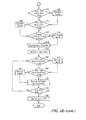
- FIG. 4D is a flow chart showing a sequence of self-tests that can be used in the self-test modules of FIGS. 3-3E , 4 , and 4 A.
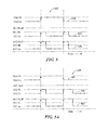
- FIGS. 5-5B are graphs showing output signals having exemplary formats that can be used by the magnetic field sensors of FIGS. 3-3E , 4 , and 4 A to indicate passing conditions and failing conditions of the magnetic field sensors;
- FIGS. 6-6B are graphs showing output signals having other exemplary formats that can be used by the magnetic field sensors of FIGS. 3-3E , 4 , and 4 A to indicate passing conditions and failing conditions of the magnetic field sensors;
- FIGS. 7-7A are graphs showing output signals having other exemplary formats that can be used by the magnetic field sensors of FIGS. 3-3E , 4 , and 4 A to indicate passing conditions and failing conditions of the magnetic field sensors;
- FIGS. 8-8A are graphs showing output signals having other exemplary formats that can be used by the magnetic field sensors of FIGS. 3-3E , 4 , and 4 A to indicate passing conditions and failing conditions of the magnetic field sensors;
- FIG. 9 is a graph showing output signals having other exemplary formats that can be used by the magnetic field sensors of FIGS. 3-3E , 4 , and 4 A to indicate passing conditions and failing conditions of the magnetic field sensors;
- FIG. 10 is a graph showing output signals having other exemplary formats that can be used by the magnetic field sensors of FIGS. 3-3E , 4 , and 4 A to indicate passing conditions and failing conditions of the magnetic field sensors;
- FIG. 11 is a graph showing output signals having other exemplary formats that can be used by the magnetic field sensors of FIGS. 3-3E , 4 , and 4 A to indicate passing conditions and failing conditions of the magnetic field sensors;
- FIG. 12 is a graph showing output signals having other exemplary formats that can be used by the magnetic field sensors of FIGS. 3-3E , 4 , and 4 A to indicate passing conditions and failing conditions of the magnetic field sensors;
- FIG. 13 is a graph showing output signals having other exemplary formats that can be used by the magnetic field sensors of FIGS. 3-3E , 4 , and 4 A to indicate passing conditions and failing conditions of the magnetic field sensors;
- FIG. 14 is a graph showing output signals having other exemplary formats that can be used by the magnetic field sensors of FIGS. 3-3E , 4 , and 4 A to indicate passing conditions and failing conditions of the magnetic field sensors;
- FIG. 15 is a graph showing output signals having other exemplary formats that can be used by the magnetic field sensors of FIGS. 3-3E , 4 , and 4 A to indicate passing conditions and failing conditions of the magnetic field sensors.
- magnetic field sensing element is used to describe a variety of electronic elements that can sense a magnetic field.
- the magnetic field sensing element can be, but is not limited to, a Hall Effect element, a magnetoresistance element, or a magnetotransistor.
- Hall Effect elements for example, a planar Hall element, a vertical Hall element, and a Circular Vertical Hall (CVH) element.
- magnetoresistance elements for example, a semiconductor magnetoresistance element such as Indium Antimonide (InSb), a giant magnetoresistance (GMR) element, an anisotropic magnetoresistance element (AMR), a tunneling magnetoresistance (TMR) element, and a magnetic tunnel junction (MTJ).
- the magnetic field sensing element may be a single element or, alternatively, may include two or more elements arranged in various configurations, e.g., a half bridge or full (Wheatstone) bridge.
- the sensing element XX may be a device made of a type IV semiconductor material such as Silicon (Si) or Germanium (Ge), or a type III-V semiconductor material like Gallium-Arsenide (GaAs) or an Indium compound, e.g., Indium-Antimonide (InSb).
- a type IV semiconductor material such as Silicon (Si) or Germanium (Ge)
- a type III-V semiconductor material like Gallium-Arsenide (GaAs) or an Indium compound, e.g., Indium-Antimonide (InSb).
- a so-called “circular vertical Hall” (CVH) sensing element which includes a plurality of vertical magnetic field sensing elements, is known and described in PCT Patent Application No. PCT/EP2008/056517, entitled “Magnetic Field Sensor for Measuring Direction of a Magnetic Field in a Plane,” filed May 28, 2008, and published in the English language as PCT Publication No. WO 2008/145662, which application and publication thereof are incorporated by reference herein in their entirety.
- the CVH sensing element includes a circular arrangement of vertical Hall elements arranged over a common circular implant region in a substrate.
- the CVH sensing element can be used to sense a direction (and optionally a strength) of a magnetic field in a plane of the substrate.
- some of the above-described magnetic field sensing elements tend to have an axis of maximum sensitivity parallel to a substrate that supports the magnetic field sensing element, and others of the above-described magnetic field sensing elements tend to have an axis of maximum sensitivity perpendicular to a substrate that supports the magnetic field sensing element.
- planar Hall elements and semiconductor magnetoresistance elements tend to have axes of sensitivity perpendicular to a substrate
- AMR, GMR, and TMR types of magnetoresistance elements and vertical Hall elements including circular vertical Hall (CVH) sensing elements
- magnetic field sensor is used to describe a circuit that includes a magnetic field sensing element.
- Magnetic field sensors are used in a variety of applications, including, but not limited to, a current sensor that senses a magnetic field generated by a current carried by a current-carrying conductor, a magnetic switch that senses the proximity of a ferromagnetic object, a rotation detector (true power on state (TPOS) detector and precision rotation detector) that senses passing ferromagnetic articles, for example, magnetic domains of a ring magnet, and a magnetic field sensor that senses a magnetic field density of a magnetic field.
- TPOS true power on state
- the term “accuracy,” when referring to a magnetic field sensor, is used to refer to a variety of aspects of the magnetic field sensor. These aspects include, but are not limited to, an ability of the magnetic field sensor to differentiate: a gear tooth from a gear valley (or, more generally, the presence of a ferromagnetic object from the absence of a ferromagnetic object) when the gear is not rotating and/or when the gear is rotating (or, more generally, when a ferromagnetic object is moving or not moving), an ability to identify an edge of a tooth of the gear from the tooth or the valley of the gear (or, more generally, the edge of a ferromagnetic object), and a rotational accuracy with which the edge of the gear tooth is identified (or, more generally, the positional accuracy with which an edge of a ferromagnetic object can be identified), i.e., output signal edge placement accuracy and consistency with respect to gear tooth edges passing by the magnetic field sensor.
- magnetic field sensors it is desirable for magnetic field sensors to achieve accuracy even in the presence of variations in an air gap between the magnetic field sensor and the gear that may change from installation to installation or from time to time. It is also desirable for magnetic field sensors to achieve accuracy even in the presence of variations in relative positions of the magnet and the magnetic field sensing element within the magnetic field sensor. It is also desirable for magnetic field sensors to achieve accuracy even in the presence of unit-to-unit variations in the magnetic field generated by a magnet within the magnetic field sensors. It is also desirable for magnetic field sensors to achieve accuracy even in the presence of variations of an axial rotation of the magnetic field sensors relative to the gear. It is also desirable for magnetic field sensors to achieve accuracy even in the presence of temperature variations of the magnetic field sensors. It is also desirable for magnetic field sensors to achieve accuracy even in the presence of wobble and/or radial asymmetry of a gear sensed by the magnetic field sensors.
- similar circuits and techniques can be used with other cams or gears disposed upon the engine camshaft, or upon other rotating parts of an engine (e.g., crank shaft, transmission gear, anti-lock braking system (ABS)), or upon rotating parts of a device that is not an engine.
- the gear is not a part of the magnetic field sensor described below.
- the gear can have ferromagnetic gear teeth.
- Examples shown below show a so-called “back-biased” arrangement, in which a permanent magnet, disposed within an integrated circuit package (or alternatively, outside of the magnetic field sensor package), provides a magnet field, which is modulated by passing ferromagnetic gear teeth.
- the magnetic field sensor can sense a changing magnetic field generated by a moving permanent magnet, for example, a ring magnet having alternating north and south poles, i.e., magnetic features.
- magnetic field sensors that can sense ferromagnetic gear teeth upon a gear configured to rotate
- the magnetic field sensors can be used in other applications.
- the other applications include, but are not limited to, sensing ferromagnetic objects, for example, soft ferromagnetic objects (with a back-biased arrangement) or hard ferromagnetic objects (i.e., permanent magnets) upon a linear structure configured to move linearly.
- self-test is used to describe functions of the magnetic field sensor that can sense, i.e., test, proper or improper operation of the magnetic field sensor.
- the term “ferromagnetic object” includes objects comprised of at least one of a soft magnetic material or a hard magnetic material.
- soft magnetic material is used herein to refer to a material (e.g., non-magnetized iron or ferrite) that is influenced by a magnetic field but that tends not to generate a magnetic field.
- hard magnetic material is used herein to refer to a material that generates a magnetic field (i.e., a magnet).
- materials that generate a magnetic field it will be understood that some non-ferrous materials (e.g., rare earth materials) can generate a magnetic field. It is intended that the term “ferromagnetic” encompass those materials as well.
- signals having particular states are shown in examples below, it should be understood that the states can be different states.
- a high state can be interchanged with a low state
- a mid-state can be interchanged with a high or a low state.
- an exemplary TPOS magnetic field sensor arrangement 10 includes a TPOS magnetic field sensor 12 .
- the TPOS magnetic field sensor 12 includes a magnetic field sensing circuit 14 having a magnetic field sensing element 16 coupled to an electronic circuit 18 .
- the TPOS magnetic field sensor 12 can also include a magnet 20 .
- the magnet 20 is configured to generate a magnetic field directed along an axis 22 .
- the electronic circuit 18 is configured to generate a TPOS output signal 24 .
- the TPOS magnetic field sensor arrangement 10 can also include a TPOS cam 26 having features 26 a , 26 b , 26 c , 26 d .
- the TPOS cam 26 can be disposed, for example, upon a shaft 30 (i.e., a target object) configured to rotate in a direction 32 .
- the cam features 26 a , 26 b , 26 c , 26 d modulate the magnetic field generated by the magnet 20 . Modulations of the magnetic field generated by the magnet 20 are sensed by the magnetic field sensing element 16 and result in state transitions in the TPOS output signal 24 .
- the TPOS magnetic field sensor 12 being able to provide the TPOS output signal 24 having transitions after only a small number of degrees of rotation of the TPOS cam 26 , which can be interpreted by the engine control computer to generate an absolute angle of rotation of the TPOS cam 26 and of the shaft 30 upon which the TPOS cam 26 is disposed.
- a graph 60 has a horizontal axis with a scale in units of target object rotation angle, for example, from 0 to 360 degrees.
- the graph 60 also includes a vertical axis having a scale with units of volts in arbitrary units.
- a signal 62 can be the same as or similar to the TPOS output signal 24 of FIG. 1 generated by the conventional TPOS magnetic field sensor 12 .
- the signal 62 can include periods 64 a , 64 b , 64 c , 64 d in which the signal 62 is in a high state and periods 66 a , 66 b , 66 c , 66 d in which the signal 62 is in a low state.
- the high state periods 64 a , 64 b , 64 c , 64 d of the signal 62 correspond to the features 26 a , 26 b , 26 c , 26 d of the TPOS cam 26 of FIG. 1 as they pass by the magnetic field sensing element 16 of FIG. 1 as the TPOS cam 26 rotates.
- an absolute angle of rotation of the cam 26 of FIG. 1 corresponding to and beginning at any point (angle) along the horizontal axis of FIG. 2 , can be identified with only a small rotation of the cam 26 of FIG. 1 , i.e., as edges of the features 26 a - 26 d pass by the magnetic field sensing element 16 .
- the conventional TPOS magnetic field sensor e.g., 12 of FIG. 1
- the conventional TPOS magnetic field sensor is able to identify if it is over a cam tooth or valley.
- an exemplary magnetic field sensor 100 is responsive to a gear 112 having ferromagnetic gear teeth, e.g., gear teeth 112 a , 112 b , 112 c .
- the magnetic field sensor 100 includes a magnetic field sensing element 102 coupled to an electronic circuit 106 .
- the magnetic field sensing element 102 and the electronic circuit 106 can be disposed upon (i.e., integrated within or upon) a substrate 104 .
- the magnetic field sensing element 102 is shown to be a Hall element with an exaggerated size for clarity. As is known, a Hall element can be integrated within the substrate 104 .
- the magnetic field sensor 100 can also include a magnet 108 .
- the magnet 108 is configured to generate a magnetic field, which is generally directed along an axis 114 at the position of the magnetic field sensing element 102 , and which is subject to direction and amplitude changes depending upon positions of the gear teeth 112 a , 112 b , 112 c relative to the magnetic field sensor 100 .
- the electronic circuit 106 is configured to generate an output signal (not shown), which can be the same as or similar to the signal 62 of FIG. 2 .
- the output signal when the gear is not moving, has a state indicative of whether the magnetic field sensor 100 is over a gear tooth or a gear valley.
- the output signal when the gear is rotating, has an edge rate or a frequency indicative of a speed of rotation of the gear. Edges or transitions of states of the output signal can be used to identify positions of edges of the gear teeth as they pass by the magnetic field sensor.
- the magnet 108 can include a central core 110 disposed within the magnet 108 .
- An exemplary magnet with a core is described in U.S. Pat. No. 6,278,269, entitled “Magnet Structure,” issued Aug. 21, 2001, which patent is assigned to the assignee of the present invention and incorporated herein by reference in its entirety.
- the pole configuration provided by the magnet 108 within the core 110 lowers the base field (or baseline) of a flux density map of the magnetic field by bringing both poles of the magnetic field to a surface of the magnet proximate to the substrate 104 .
- a predetermined baseline e.g., within a range of about +/ ⁇ six hundred Gauss
- a resulting differential magnetic field signal 102 a , 102 b i.e., an analog differential proximity signal
- the magnetic field sensing element 102 experiences a higher magnetic field and generates the differential proximity signal 102 a , 102 b with a high value.
- the baseline remains constant even as the air gap between the gear teeth and the magnetic field sensor 100 varies.
- This advantageous result of low baseline substantially independent of air gap is achieved by presenting opposite poles at the face of the magnet 108 and core 110 proximate to the magnetic field sensing element. This effect is also described in U.S. Pat. No. 5,781,005, issued Jul. 14, 1998, entitled “Hall-Effect Ferromagnetic-Article-Proximity Sensor,” which patent is assigned to the assignee of the present invention and incorporated herein by reference in its entirety.
- the magnetic field sensor 100 can be referred to as a “tooth detector,” as opposed to “edge detectors” described below.
- the magnetic field described above and provided by the magnet 108 with the core 110 results in an improved accuracy of the magnetic field sensor 100 .
- the improved magnetic field allows the magnetic field sensing element 102 to be somewhat statically misaligned from a center of the magnet 108 , as will occur due to unit-to-unit variations of mechanical alignments, without sacrificing accuracy of the magnetic field sensor 100 . Accuracy is discussed above.
- an exemplary electronic circuit 120 can be the same as or similar to electronic circuit 106 of FIG. 3 .
- the electronic circuit 120 can include a processing module 121 having an amplifier 124 coupled to receive a differential proximity signal 122 a , 122 b , which can be the same as or similar to the differential proximity signal 102 a , 102 b generated by the magnetic field sensing element 102 of FIG. 3 .
- the amplifier 124 is configured to generate an amplified signal 124 a (also referred to herein as a proximity signal), which, in some embodiments, can split into two channels.
- a TPOS detector 126 can be coupled to receive the amplified signal 124 a and configured to generate a TPOS output signal 126 a .
- the TPOS detector 126 can include a comparator (not shown) configured to compare the amplified signal 126 a with a fixed predetermined (and trimmed) threshold.
- the TPOS output signal 126 a can be a two-state binary signal for which a high state is indicative of a gear tooth being proximate to the magnetic field sensor 100 of FIG. 3 and a low state is indicative of a gear valley being proximate to the magnetic field sensor 100 , or vice versa.
- an automatic gain control (AGC) 128 can be coupled to receive the amplified proximity signal 124 a and configured to generate a gain controlled signal 128 a .
- a precision rotation detector 130 can be coupled to receive the gain controlled signal 128 a and configured to generate a precision rotation detector output signal 130 a .
- the precision rotation detector output signal 130 a can be a two-state binary signal for which a high state is indicative of a gear tooth being proximate to the magnetic field sensor 100 of FIG. 3 and a low state is indicative of a gear valley being proximate to the magnetic field sensor 100 , or vice versa.
- both the TPOS detector 126 and the precision rotation detector 130 can be “tooth detectors.”
- the precision rotation detector 130 can be an “edge detector,” which is unable to identify whether the magnetic field sensor 102 is proximate to a gear tooth or a gear valley, particularly when the gear is not moving.
- a low to high state transition of the precision rotation detector output signal 130 a can be indicative of a transition from a gear valley being proximate to the magnetic field sensing element 102 to a gear tooth being proximate to the magnetic field sensing element 102
- a high to low state transition can be indicative of a transition from the gear tooth being proximate to the magnetic field sensing element 102 to a gear valley thing proximate to the magnetic field sensing element 102 , or vice versa.
- the precision rotation detector 130 can be coupled to, or can otherwise include, a calibration/running mode control module 131 .
- the calibration/running mode control module 131 can be operable to cause the precision rotation detector 130 to use first thresholds for comparison with the gain controlled signal 128 a during a “calibration mode,” usually for a short time period following a beginning of rotation of the gear that is being sensed. Thereafter, the calibration/running mode control module 131 can be operable to cause the precision rotation detector 130 to use second different thresholds accurately determined by the precision rotation detector 130 during a “running mode.”
- Precision rotation detectors e.g., the precision rotation detector 130
- the TPOS output signal 126 a is able to identify whether the magnetic field sensing element 102 is proximate to a gear tooth or to a gear valley, even when the gear, e.g., the gear 152 of FIG. 3 is stationary.
- the TPOS detector 126 uses a fixed threshold, variations in the edge placement in the TPOS output signal 126 a will occur due to a variety of factors, including, but not limited to, temperature variations, and variations in the air gap between the magnetic field sensing element 102 and the gear 152 .
- the precision rotation detector 130 continually makes adjustments of thresholds to provide the precision rotation detector output signal 130 a with better accuracy of edge placements of the precision rotation detector output signal 130 a relative to physical positions of gear teeth, and edges of gear teeth in particular.
- a multiplexer 134 can be coupled to receive the TPOS output signal 126 a and coupled to receive the precision rotation detector output signal 130 a .
- Select logic 132 can provide a selection signal 132 a , received by the multiplexer/output module 134 .
- the multiplexer 134 is configured to generate a signal 134 a representative of a selected one of the TPOS output signal 126 a or the precision rotation detector output signal 130 a.
- the signal 134 a is representative of rotation of the gear 112 of FIG. 3 , and thus, is also referred to herein as a “rotation signal.”
- the rotation signal has a first state associated with a gear tooth and a second different state associated with a valley in the gear 112 .
- the select logic 132 can be coupled to receive the TPOS output signal 126 a .
- the select logic 132 selects the signal 134 a to be representative of the TPOS output signal 126 a for a predetermined amount of time after the gear 152 starts rotating as indicated by the TPOS output signal 126 a . Thereafter, the select logic 132 selects the signal 134 a to be representative of the precision rotation detector output signal 130 a.
- Other magnetic field sensors can include only the TPOS channel having the TPOS detector 126 or only the precision rotation detector channel having the precision rotation detector 130 .
- the electronic circuit 120 can also include a self-test module 136 .
- the self-test module 136 can be coupled to receive one or more tested signals 144 described more fully below in conjunction with FIGS. 4 , 4 B, 4 C, and 4 D.
- the self-test module 136 is configured to generate a self-test signal 136 a .
- the self-test signal 136 a is a two-state signal representative of a passing condition or a failing condition of the electronic circuit 120 and/or of a magnetic field sensing element to which the electronic circuit 120 is coupled.
- the self-test signal 136 a is a signal having more than two states representative of more than two self-test conditions of the electronic circuit 120 , for example, specific failures of the electronic circuit 120 and/or of a magnetic field sensing element to which the electronic circuit 120 is coupled.
- the electronic circuit 120 can also include a power-on sensing module 138 configured to generate a power-on signal 138 a .
- the power-on signal 138 a can be a two state signal with a first state representative of a time from a power on of the electronic circuit 120 to a predetermined time after the power on, and with a second state representative of a time after the predetermined time.
- a self-test format module 142 can be coupled to receive the self-test signal 136 a .
- the self-test format module 142 is configured to provide an output signal 142 a having a format indicative of the passing condition, the failing condition, or a specific failing condition of the electronic circuit 120 and/or of a magnetic field sensing element to which the electronic circuit 120 is coupled.
- a combined format module 140 can be coupled to receive the self-test signal 136 a and coupled to receive the sensed-magnetic-field signal 134 a .
- the combined format module 140 is configured to provide an output signal 140 a having a format indicative of the passing condition, the failing condition, or a specific failing condition of the electronic circuit 120 and/or of a magnetic field sensing element to which the electronic circuit 120 is coupled, and also indicative of a magnetic field detected by a magnetic field sensing element to which the electronic circuit 120 is coupled.
- One or more of the signals 134 a , 140 a , 142 a can be coupled to a respective one or more pins on a lead frame in an integrated circuit. Couplings are described more fully below in conjunction with FIGS. 4 and 4A .
- another exemplary magnetic field sensor 150 is responsive to a gear 162 having gear teeth, e.g., gear teeth 162 a , 162 b , 162 c .
- the magnetic field sensor 150 includes two magnetic field sensing elements 152 , 154 coupled to an electronic circuit 158 .
- the two magnetic field sensing elements 152 , 154 are separated in a direction perpendicular to an axis 214 and parallel to a gear by a distance between about 1.5 millimeters and about 3.0 millimeters.
- the magnetic field sensing elements 152 , 154 can be separated by a distance between about 0.5 millimeters and 1.5 millimeters.
- the magnetic field sensing elements can be separated by more than 3.0 millimeters.
- the two magnetic field sensing elements 152 , 154 and the electronic circuit 158 can be disposed upon (i.e., integrated within or upon) a substrate 156 .
- the magnetic field sensing elements 152 , 154 are shown to be Hall elements with an exaggerated size for clarity.
- the magnetic field sensor 150 can also include a magnet 160 .
- the magnet 160 is configured to generate a magnetic field, which is generally directed along the axis 164 at the position of the magnetic field sensing elements 152 , 154 .
- the electronic circuit 150 is configured to generate an output signal (not shown). Let it suffice here to say that the electronic circuit 150 generates a difference of two differential proximity signals 152 a , 152 b , and 154 a , 154 b .
- the magnetic field sensor 150 using the differencing arrangement, forms an edge detector, able to detect passing edges of gear teeth, but unable to differentiate a gear tooth from a gear valley.
- the output signal when the gear 162 is rotating, is indicative speed of rotation of the gear 162 and also indicative of positions of edges of the gear teeth.
- the magnetic field sensor 150 is unable to provide a TPOS function (which must differentiate a gear tooth from a gear valley)
- the magnetic field sensor 150 is unable to identify whether the magnetic field sensing elements 152 , 154 are proximate to a gear tooth or a valley in the gear 162 .
- the magnet 160 can be comprised of one uniform material, and can have no central core, which is shown and described in conjunction with FIG. 3 . However, in other embodiments, the magnet 160 can have a central core the same as or similar to that shown and described in FIG. 3 .
- the central core 110 results in a low baseline when the magnetic field sensing element 102 of FIG. 3 is proximate to a valley in the gear 152 .
- the magnetic field sensor 150 uses two magnetic field sensing elements, generating a respective two differential output signals 152 a , 152 b and 154 a , 154 b .
- signals representative of the two differential output signals 152 a , 152 b and 154 a , 154 b are subtracted in the electronic circuit 158 .
- the low baseline is achieved due to the differencing arrangement, since the two magnetic field sensing elements 152 , 154 experience the same, or a similar, magnetic field. Also, when the two magnetic field sensing elements 152 , 154 are proximate to a gear tooth, e.g., 162 a , 162 b , 162 c , the low baseline is also achieved, since the two magnetic field sensing elements 152 , 154 again experience the same, or a similar, magnetic field.
- the higher value may occur when one of the magnetic field sensing elements is proximate to a valley in the gear 162 and the other magnetic field sensing element is proximate to a gear tooth, i.e., an edge of one of the gear teeth is between the two magnetic field sensing elements 152 , 154 .
- the magnetic field sensor 150 having two magnetic field sensing elements used in a differential arrangement, is sometimes referred to as an “edge detector.”
- the edge detecting behavior makes the magnetic field sensor 150 particularly useful when it is necessary to accurately know the rotational position of the gear, which can be determined by knowledge of positions of the edges of the gear teeth represented by state transitions in the output signal from the magnetic field sensor 150 .
- the differencing of the two differential signals 152 a , 152 b and 154 a , 154 b results in an improved accuracy of the magnetic field sensor 150 .
- the magnetic field sensor 150 is not influenced by external magnetic fields, i.e., noise magnetic fields, that both of the two magnetic field sensing elements 152 , 154 experience.
- an exemplary electronic circuit 170 can include a processing module 171 having amplifiers 176 , 178 coupled to receive differential signals 172 a , 172 b , and 174 a , 174 b , respectively.
- the differential signal 172 a , 172 b can be the same as or similar to the differential signal 152 a , 152 b and the differential signal 174 a , 174 b can be the same as or similar to the differential signal 154 a , 154 b generated, respectively, by the magnetic field sensing elements 152 , 154 of FIG. 3B .
- the amplifiers 176 , 178 are configured to generate amplified signals 176 a , 178 a , respectively.
- the amplified signals 176 a , 178 a are received by a differencing module 180 , which is configured to generate a difference signal 180 a (a proximity signal). Characteristics and behaviors of the difference signal 180 a will be understood from the discussion above.
- the electronic circuit 170 includes only the precision rotation detector channel described above in conjunction with FIG. 3A .
- An AGC 182 can be the same as or similar to the AGC 128 of FIG. 3A
- a precision rotation detector 184 can be the same as or similar to the precision rotation detector 130 of FIG. 3A
- a calibration/running mode control module 183 can be the same as or similar to the calibration/running mode control module 131 of FIG. 3A .
- the precision rotation detector 184 can generate a precision rotation detector output signal 184 a.
- the electronic circuit 170 can also include a self-test module 190 , a power-on sensing module 192 , a self-test format module 196 , and a combined format module 194 , which can be the same as or similar to the self-test module 136 , the power-on sensing module 138 , the self-test format module 142 , and the combined format module 140 of FIG. 3A .
- another exemplary conventional magnetic field sensor 220 is responsive to a gear 234 having gear teeth, e.g., gear teeth 234 a , 234 b , 234 c .
- the magnetic field sensor 220 includes three magnetic field sensing elements 222 , 224 , 226 coupled to an electronic circuit 230 .
- the magnetic field sensing elements 222 , 224 are separated in a direction perpendicular to an axis 236 by a distance between about 1.5 millimeters and about 3.0 millimeters, and the magnetic field sensing element 226 is located midway between the magnetic field sensing elements 222 , 224 .
- the three magnetic field sensing elements 222 , 224 , 226 and the electronic circuit 230 can be disposed upon (i.e., integrated within or upon) a substrate 228 .
- the magnetic field sensing elements 222 , 224 , 226 are shown to be Hall elements with an exaggerated size for clarity.
- the magnetic field sensor 220 can also include a magnet 232 .
- the magnet 232 is configured to generate a magnetic field, which is generally directed along an axis 236 at the position of the magnetic field sensing elements 222 , 224 , 226 .
- the electronic circuit 230 is configured to generate an output signal (not shown).
- An exemplary electronic circuit 230 is described below in conjunction with FIG. 3E . Let it suffice here to say that the electronic circuit 230 , like the electronic circuit 230 of FIG. 3C above, generates a difference of signals.
- the magnetic field sensor 220 is an edge detector and not a tooth detector.
- the output signal when the gear 234 is rotating, is indicative speed of rotation of the gear 234 , indicative of positions of edges of the gear teeth, and can also be indicative of a direction or rotation of the gear 234 .
- the magnetic field sensor 220 is unable to provide a TPOS function, and, when the gear 234 is stationary, is unable to identify whether the magnetic field sensing elements 222 , 224 , 226 are proximate to a gear tooth or a valley in the gear 234 .
- the magnet 232 can be comprised of one uniform material, and can have no central core, which is shown and described in conjunction with FIG. 3 . However, in other embodiments, the magnet 232 can have a central core the same as or similar to that shown and described in conjunction with FIG. 3 .
- the differencing of pairs of three differential signals 222 a , 222 b , and 224 a , 224 b , and 226 a , 226 b results in an improved accuracy of the magnetic field sensor 220 .
- the magnetic field sensor 220 is not influenced by external magnetic fields, i.e., noise magnetic fields, that the three magnetic field sensing elements 222 , 224 , 226 experience.
- an exemplary electronic circuit 240 can be the same as or similar to the electronic circuit 230 of FIG. 3D .
- the electronic circuit 240 can include a processing module 241 having amplifiers 248 , 250 , 252 coupled to receive differential signals 242 a , 242 b , and 244 a , 244 b , and 246 a , 246 b , respectively.
- the differential signal 242 a , 242 b can be the same as or similar to the differential signal 222 a , 222 b
- the differential signal 244 a , 244 b can be the same as or similar to the differential signals 224 a , 224 b
- the differential signal 246 a , 246 b can be the same as or similar to the differential signal 226 a , 226 b generated, respectively, by the magnetic field sensing elements 222 , 224 , 226 of FIG. 3D
- the amplifiers 248 , 250 , 252 are configured to generate amplified signals 248 a , 250 a , 252 a , respectively.
- the amplified signals 248 a , 252 a are received by a first differencing module 254 , which is configured to generate a first difference signal 254 a (a proximity signal).
- the amplified signals 250 a , 252 a are received by a second differencing module 256 , which is configured to generate a second difference signal 256 a (a proximity signal). Characteristics and behaviors of the difference signals 254 a , 256 a will be understood from the discussion above.
- the electronic circuit 240 includes only precision rotation detector channels described above in conjunction with FIG. 3A . Only one of the two precision rotation detector channels is described herein as being representative of the other precision rotation detector channel.
- An AGC 260 can be the same as or similar to the AGC 128 of FIG. 3A
- a precision rotation detector 264 can be the same as or similar to the precision rotation detector 130 of FIG. 3A
- a calibration/running mode control module 265 can be the same as or similar to the calibration/running mode control module 131 of FIG. 3A .
- the precision rotation detector 264 can generate a precision rotation detector output signal 264 a.
- a speed/direction module 268 can be coupled to receive the precision rotation detector output signal 264 a and also another precision rotation detector output signal 266 a .
- the speed/direction module 268 is configured to generate an output signal 268 a representative of a speed of rotation and a direction of rotation of the gear 234 .
- the direction information can be determined by way of a phase difference of the two precision rotation detector output signals 264 a , 266 a
- the speed information can be determined by way of a frequency of either one of the two precision rotation detector output signals 264 a , 266 a.
- the electronic circuit 240 can also include a self-test module 272 , a power-on sensing module 270 , a self-test format module 276 , and a combined format module 274 , which can be the same as or similar to the self-test module 136 , the power-on sensing module 138 , the self-test format module 142 , and the combined format module 140 of FIG. 3A .
- While magnetic field sensors described above in conjunction with FIGS. 3-3E are shown to include respective automatic gain control circuits (AGCs) configured to generate respective gain-controlled signals, in other embodiments, the AGCs can be replaced by fixed gain amplifiers or buffers. For embodiments in which the gain of the amplifiers are fixed, it should be understood that the gain of the amplifiers can be greater that one, less than one, or one.
- AGCs automatic gain control circuits
- FIGS. 4-4D show particular examples of self-test modules and self-test methods that can be used in conjunction with the magnetic field sensor shown above in conjunction with FIG. 3 . It should be recognized that other self-test modules and other self-test methods can be used and the other self-test modules and other self-test methods can be used in conjunction with other magnetic field sensors.
- an exemplary magnetic field sensor 300 can include the processing module 121 and the self-test module 136 of FIG. 3A .
- the self-test module 136 is shown in greater detail.
- the magnetic field sensor 300 can include a plurality of nodes or pins, here shown as five nodes or pins 300 a - 300 e . However, it will be understood from the discussion below in conjunction with FIG. 4A , that fewer nodes or pins can be used, i.e., two or three nodes or pins.
- the processing module 121 is coupled to receive the differential signal 122 a , 122 b generated by one or more magnetic field sensing elements, shown here as two Hall effect elements 340 , 342 .
- the two Hall Effect elements 340 , 342 are coupled to receive a drive signal 338 a generated by an element drive circuits 338 .
- the drive signal 338 a is a DC current signal.
- the two Hall effect elements 340 , 342 can be coupled to a switching network 344 , which can couple the two Hall effect elements 340 , 342 into two different configurations referred to herein as a diagnostic mode configuration and a normal mode configuration. These two configurations are the same as or similar to configurations discussed in U.S. patent application Ser. No. 12/840,324, entitled “Circuits and Methods for Generating a Diagnostic Mode of Operation in a Magnetic Field Sensor,” filed Jul. 21, 2010, assigned to the assignee of the present application, and incorporated by reference herein in its entirety.
- the two Hall Effect elements 340 , 342 when coupled in the diagnostic mode configuration, the two Hall Effect elements 340 , 342 are coupled in opposition, and when coupled in the normal mode configuration, the two Hall Effect elements 340 , 342 are coupled in reinforcement. Thus, when coupled in the diagnostic mode configuration, the two Hall Effect elements 340 , 342 taken together are not responsive to an external magnetic field.
- two drive coils (or conductors) can be driven with currents in opposite directions to generate a differential output signal 122 a , 122 b from the two Hall Effect elements.
- a differential drive signal 322 a , 322 b can be directly applied to the two Hall elements 340 , 342 to generate the differential signal 122 a , 122 b.
- the two methods described above will be understood to generate the differential signal 122 a , 122 b as a synthetic signal used for self-test purposes.
- the two methods described above are referred to herein as a “stimulus.”
- the processing module 121 is configured to generate, and the self-test module 136 is configured to receive, a plurality of signals, one or more of which can be tested by the self-test module 136 .
- the processing module 121 is configured to generate the proximity signal 124 a , the gain controlled signal 128 a , a threshold signal 130 b , and an analog-to-digital converter (ADC) signal 126 b , one or more of which can be received by the self-test module 136 .
- ADC analog-to-digital converter
- the self-test module 136 can include one or more of a built-in self-test (BIST) detector 302 , a proper peak detector 304 , a proper ADC detector 306 , a proper AGC detector 308 , a proper threshold detector 310 , a proper drive signals detector 312 , a proper current detector 314 , or a proper voltage detector 316 .
- BIST built-in self-test
- the BIST detector 302 can be configured to generate a BIST enable signal 392 b , which can initiate a self-test of a variety of circuits within the magnetic field sensor 300 , including, but not limited to, memory devices.
- the BIST detector 302 can be coupled to receive a BIST signal 350 indicative of the ongoing BIST test.
- the BIST detector can be configured to generate a BIST signal 302 a indicative of a passing condition or a failing condition of the BIST test.
- the proper peak detector 304 can be coupled to receive the proximity signal 124 a , which is an analog signal.
- the proper peak detector 304 can be configured to convert the proximity signal 124 a to a digital signal and to process the digitized proximity signal to identify peak values of the digitized proximity signal.
- the proper peak detector 304 can be configured to compare the peak values of the digitized proximity signal with one or more threshold values to identify if the peak values are in a proper range of magnitudes.
- the proper peak detector 304 can be configured to generate a signal 304 a indicative of a passing condition or a failing condition of the test for proper peak magnitudes of the proximity signal 124 a.
- the proper ADC detector 306 can be coupled to receive the ADC signal 126 b , which is a digital signal.
- the proper ADC detector 306 can be configured to compare the ADC signal 126 b with one or more threshold values to identify if the ADC signal 126 b is within a proper range of magnitudes.
- the proper ADC detector 306 can be configured to generate a signal 306 a indicative of a passing condition or a failing condition of the tests for proper magnitudes of the ADC signal 126 b.
- the proper AGC detector 308 can be coupled to receive the gain controlled signal 128 a , which is an analog signal.
- the proper AGC detector 308 can be configured to convert the gain controlled signal 128 a to a digital signal and to process the digitized gain controlled signal to identify peak values of the digitized gain control signal.
- the proper AGC detector 308 can be configured to compare the peak values of the digitized gain controlled signal with one or more threshold values to identify if the peak values are in a proper range of magnitudes.
- the proper AGC detector 308 can be configured to generate a signal 308 a indicative of a passing condition or a failing condition of the test for proper peak magnitudes of the gain controlled signal 128 a.
- the proper threshold detector 310 can be coupled to receive the threshold signal 130 b , which is an analog signal.
- the proper threshold detector 310 can be configured to convert the threshold signal 130 b to a digital signal and to process the digitized threshold signal.
- the proper threshold detector 310 can be configured to compare the digitized threshold signal with one or more threshold values to identify if the digitized threshold signal is within a proper range of values.
- the proper threshold detector 310 can be configured to generate a signal 310 a indicative of a passing condition or a failing condition of the test for proper values of the threshold signal 130 b.
- the proper drive signals detector 312 can be coupled to receive a signal 338 b , which can be an analog signal applied to the two Hall Effect elements 344 , 346 , and which can be representative of the drive signals 338 a provided to the two Hall Effect elements 340 , 342 .
- the proper drive signals detector 312 can be configured to convert the signal 338 b to a digital signal and to process the digitized signal.
- the proper drive signals detector 312 can be configured to compare the digitized signal 338 b with one or more threshold values to identify if the signal 338 b is within a proper range of values.
- the proper drive signals detector 312 can be configured to generate a signal 312 a indicative of a passing condition or a failing condition of the test for proper values of the signal 338 a.
- the proper current detector 314 can be coupled to receive a power supply voltage 301 , which is an analog voltage, and which is used to power the magnetic field sensor 300 .
- the proper current detector 314 can be configured to generate an output signal 314 b , which ultimately powers the magnetic field sensor 300 .
- the proper current detector 314 can be configured to identify a magnitude of the current passing through the proper current detector 314 .
- the proper current detector 314 can be configured to generate a signal 314 a indicative of a passing condition or a failing condition of the test for proper values of the current that powers the magnetic field sensor 300 .
- the proper voltage detector 316 can be coupled to receive a regulated power supply voltage 328 a , which is an analog voltage, and which is generated by a voltage regulator 328 , which is coupled to receive the signal 314 b from the proper current detector 314 .
- the proper voltage detector 316 can be configured to convert the voltage signals 328 a to a digital signal and to process the digitized signal.
- the proper voltage detector 316 can be configured to compare the digitized signal with one or more threshold values to identify if the digitized signal is within a proper range of values.
- the proper voltage detector 316 can configured to generate a signal 316 a indicative of a passing condition or a failing condition of the test for proper values of the digitized voltage signal 328 a.
- the self-test module 136 can also include a sequence module 326 .
- the sequence module 326 can be configured to generate a sequence signal 326 a , which can control a sequence of the various self-tests represented by the various detector modules.
- the self-test module 136 can also include one or more logic gates 320 coupled to receive one or more of the signals 302 a , 304 a , 306 a , 308 a , 310 a , 312 a , 314 a , 316 a .
- the one or more logic gates 320 can be configured to generate the signal 136 a representative of a passing condition or a failing condition of the magnetic field sensor 300 .
- the signal 136 a is a two state binary signal, and, in other embodiments, the signal 136 a is a multi-bit digital signal representative of passing conditions and failing conditions of specific ones of the self-test embodied by the various detectors within the self-test module 136 .
- the magnetic field sensor 300 can also include a power on sensing circuit 138 configured to generate a power on signal 138 a indicative of a time period beginning at a power on of the magnetic field sensor 300 .
- the sequence module 326 can begin the sequence of self-tests upon power up of the magnetic field sensor 300 or at any predetermined time thereafter.
- the self-test module 136 can include a coil driver circuit 324 coupled to receive the sequence signal 326 a and configured to generate drive current signals 324 a , 324 b to the coils 346 , 348 (or conductors).
- the self-test module 136 can also include a simulated signal driver 322 coupled to receive the sequence signal 326 a and configured to generate the drive signals 322 a , 322 b.
- either the current signal 324 a , 324 b or the simulated signal 322 a , 322 b can be used as the stimulus required for some or all of the self-tests embodied in the various detectors of the self-test module 136 . It will be particularly appreciated that the current signal stimulus 324 a , 324 b can test the entire magnetic field sensor 300 including the Hall Effect elements 340 , 342 .
- a magnetic fields sensor 400 can include a digital format module 402 coupled to receive one or more of the sensed magnetic field signal 134 a , the combined signal 140 a , or the self-test signal 142 a .
- the digital format module 402 can be configured to generate an output signal 402 a representative of at least the passing condition or the failing condition represented by the self-test signal 142 a , but which, in some embodiments, can also be representative of the sensed-magnetic-field signal 134 a .
- the signal 402 a can be provided in one of a variety of formats described more fully below.
- the magnetic field sensor 400 can also include a voltage to current converter coupled to receive one or more of the combined signal 140 a or the self-test signal 142 a .
- the voltage to current converter 404 can be configured to impress a varying current upon a received power supply voltage signal 406 , wherein the varying current is representative of at least the passing condition or the failing condition represented by the self-test signal 142 , but which can also be representative of the sensed-magnetic-field signal 134 a .
- the current portion of the signal 406 can be provided in one of a variety of formats described more fully below.
- a processing module 450 can be the same as or similar to the processing module 121 of FIG. 3A , but not including the amplifier 124 of FIG. 3A .
- the processing module 450 can include a TPOS detector 466 and a precision rotation detector 451 , which can be the same as or similar to the TPOS detector 128 and the precision rotation detector 130 of FIG. 3A .
- the electronic circuit 450 can include an automatic gain control 464 , which can be the same as or similar to the automatic gain control 128 of FIG. 3A .
- the electronic circuit 450 can be coupled to receive a proximity signal 452 , which can be the same as or similar to the proximity signal 124 a of FIG. 3A .
- the proximity signal 452 is representative of the magnetic field experienced by one or more magnetic field sensors, for example, the magnetic field sensors 340 , 342 of FIG. 4 .
- the TPOS detector 466 can be comprised of a comparator 468 coupled to receive the proximity signal 452 at a first input node and coupled to receive a predetermined threshold signal (i.e., voltage) 470 at a second input node.
- the TPOS detector 466 is configured to generate a TPOS output signal 468 a , which can be the same as or similar to the TPOS output signal 126 a of FIGS. 3A and 4 .
- the automatic gain control 464 is coupled to receive the proximity signal 452 .
- the proximity signal 452 has a DC offset correction applied by an automatic offset controller 454 and an offset digital-to-analog converter (DAC) 456 via a summing node 458 .
- the AGC 464 is configured to generate a gain controlled signal 464 aa , which can be the same as or similar to the gain controlled signal 128 a of FIGS. 3A and 4 .
- the AGC 464 can be controlled by an AGC DAC 460 .
- the gain controlled signal 464 a is provided as an input to a comparator 502 .
- the comparator 502 is also coupled to receive a threshold signal 500 . Generation of the threshold signal 500 is further described below.
- the threshold signal 500 switches between two signals 500 a , 500 b , a first one 500 a of which is a first predetermined percentage (e.g., sixty percent) of a peak-to-peak value of the gain controlled signal 464 a and a second one 500 b of which is a second predetermined percentage (e.g., forty percent) of the peak-to-peak value of the gain controlled signal 464 a .
- the first and second threshold voltages 500 a , 500 b are, therefore, centered about a fifty percent point of the gain controlled signal 464 a .
- the comparator 502 generates an output signal 502 a having edges closely associated with the times when the gain controlled signal 464 a crosses the two thresholds 500 a , 500 b , which times are near to times when the gain controlled signal 464 a is near its fifty percent point.
- the output signal 502 a can be the same as or similar to the high precision rotation detector output signal 130 a of FIGS. 3A and 4 .
- the threshold voltages 500 a , 500 b within the threshold signal 500 are generated by counters 476 , 478 , logic circuits 474 , 480 , a PDAC 486 , an NDAC 488 , comparators 482 , 484 , a resistor ladder 490 , and transmission gates 494 , 496 .
- the comparator 482 is coupled to receive the gain controlled signal 464 a and an output signal 486 a generated by the PDAC 486 , and, by way of feedback provided by the logic circuit 474 and the counter 476 , causes the output of the PDAC 486 (i.e., the PDAC voltage 486 a ) to track and hold positive peaks of the gain controlled signal 464 a .
- the comparator 484 is coupled to receive the gain controlled signal 464 a and an output signal 488 a generated by the NDAC 488 , and, by way of feedback provided by the logic circuit 480 and the counter 478 , causes the output of the NDAC 488 (i.e., the NDAC voltage 488 a ) to track and hold negative peaks of the gain controlled signal 464 a . Therefore, the differential voltage between the output 486 a of the PDAC 486 and the output 488 a of the NDAC 488 is representative of a peak-to-peak amplitude of the gain controlled signal 464 a.
- the PDAC and NDAC voltages 486 a , 488 a are provided to opposite ends of the resistor ladder 490 .
- Transmission gates 494 , 496 provide the threshold voltage 500 as one of two voltage values as described above, depending upon control voltages (not shown) applied to the transmission gates 494 , 496 .
- the control voltages can be related to the output signal 502 a.
- the electronic circuit 450 provides the proximity signal 452 , the threshold signal 500 , and the gain controlled signal 464 a , which can be the same as or similar to the proximity signal 124 a , the threshold signal 130 b , and the gain controlled signal 128 a of FIGS. 3A and 4 .
- the ADC signal 126 b is not generated by the electronic circuit 450 .
- the ADC signal 126 b is described below in conjunction with FIG. 4C .
- an electronic circuit 520 can include a different TPOS detector 522 .
- the TPOS detector 522 can include an analog-to-digital converter 524 coupled to receive the proximity signal 452 and configured to generate a digitized proximity signal 524 a .
- a threshold generating circuit 526 can be configured to generate a digital threshold value 526 a .
- a magnitude comparator 528 i.e., a digital comparator
- the digitized proximity signal 524 a can be provided to the self-test module 136 of FIG. 4 as the ADC signal 126 b.
- FIG. 4D show a flowchart corresponding to the below contemplated technique which would be implemented in magnetic field sensor (e.g., 300 , FIG. 4 ).
- Rectangular elements (typified by element 552 in FIG. 4D ), herein denoted “processing blocks,” represent computer software instructions or groups of instructions.
- Diamond shaped elements (typified by element 554 in FIG. 4D ), herein denoted “decision blocks,” represent computer software instructions, or groups of instructions, which affect the execution of the computer software instructions represented by the processing blocks.
- the processing and decision blocks represent steps performed by functionally equivalent circuits such as a digital signal processor circuit or an application specific integrated circuit (ASIC).
- ASIC application specific integrated circuit
- the flow diagrams do not depict the syntax of any particular programming language. Rather, the flow diagrams illustrate the functional information one of ordinary skill in the art requires to fabricate circuits or to generate computer software to perform the processing required of the particular apparatus. It should be noted that many routine program elements, such as initialization of loops and variables and the use of temporary variables are not shown. It will be appreciated by those of ordinary skill in the art that unless otherwise indicated herein, the particular sequence of blocks described is illustrative only and can be varied without departing from the spirit of the invention. Thus, unless otherwise stated the blocks described below are unordered meaning that, when possible, the steps can be performed in any convenient or desirable order.
- an exemplary process 550 is representative of a set of tests as may be generated by the self-test module 136 of FIG. 4 , in a sequence as may be determined by the sequence module 326 of FIG. 4 .
- the exemplary process 550 is merely an example. Any number of other modules can perform self-tests in any number of different sequences.
- the process 550 begins at block 552 where a stimulus is set to off.
- the stimulus can be one of two different types of stimuli.
- the stimulus can be generated by the coils 346 , 348 of FIG. 4 , or the stimulus can be provided by the differential drive signal 322 a , 322 b.
- peaks of the proximity signal for example the proximity signal 124 a of FIG. 4 , are within predetermined limits. This determination can be made, for example, by the proper peak detector 304 of FIG. 4 . If the peaks are within the predetermined limits, the process continues to block 556 .
- the proximity signal 124 a should have peaks within the certain limits, and the magnitude of the peaks is representative of the air gap between the magnetic field sensing elements, e.g., 340 , 342 of FIG. 4 , and the teeth of the gear 112 .
- the peaks of the proximity signal 124 a should be zero.
- peaks of the gain controlled signal for example, the gain controlled signal 128 a of FIG. 4 , are within predetermined limits. This determination can be made, for example, by the proper AGC detector 308 of FIG. 4 . If the peaks are within the predetermined limits, then the process continues to block 558 .
- the stimulus is set to be on and to a positive DC value, which guarantees that the differential signal 122 a , 122 b of FIG. 4 has a positive DC component of a predetermined magnitude.
- the magnitude of the proximity signal 124 a is positive and is related to either a magnitude of the differential drive signal 324 a , 324 b of FIG. 4 or to a magnitude of the differential drive signal 322 a , 322 b , depending upon which type of stimulus is selected.
- a DC magnitude of the proximity signal for example the proximity signal 124 a of FIG. 4 , is within predetermined limits. This determination can be made, for example, by the proper peak detector 304 of FIG. 4 . If the DC magnitude is within the predetermined limits, the process continues to block 564 .
- a DC magnitude of the gain controlled signal for example, the gain controlled signal 128 a of FIG. 4 , is within predetermined limits. This determination can be made, for example, by the proper AGC detector 308 of FIG. 4 . If the DC magnitude is within the predetermined limits, then the process continues to block 564 .
- a DC magnitude of the ADC signal for example, the ADC signal 126 b of FIG. 4 , is within predetermined limits. This determination can be made, for example, by the proper ADC detector 306 of FIG. 4 . If the DC magnitude is within the predetermined limits, then the process continues to block 566 .
- a DC magnitude of the threshold signal for example, the threshold signal 130 b of FIG. 4 . This determination can be made, for example, by the proper threshold detector 310 of FIG. 4 . If the DC magnitude is within the predetermined limits, then the process continues to block 568 .
- the stimulus is turned on and to a negative value, which guarantees that the differential signal 122 a , 122 b of FIG. 4 has a negative DC component of a predetermined magnitude.
- a DC magnitude of the proximity signal for example the proximity signal 124 a of FIG. 4 , is within predetermined limits. This determination can be made, for example, by the proper peak detector 304 of FIG. 4 . If the DC magnitude is within the predetermined limits, the process continues to block 570 .
- a DC magnitude of the gain controlled signal for example, the gain controlled signal 128 a of FIG. 4 , is within predetermined limits. This determination can be made, for example, by the proper AGC detector 308 of FIG. 4 . If the DC magnitude is within the predetermined limits, then the process continues to block 572 .
- a DC magnitude of the ADC signal for example, the ADC signal 126 b of FIG. 4 , is within predetermined limits. This determination can be made, for example, by the proper ADC detector 306 of FIG. 4 . If the DC magnitude is within the predetermined limits, then the process continues to block 566 .
- a DC magnitude of the threshold signal for example, the threshold signal 130 b of FIG. 4 . This determination can be made, for example, by the proper threshold detector 310 of FIG. 4 . If the DC magnitude is within the predetermined limits, then the process continues to block 578 .
- the stimulus is turned on and to a positive value, which guarantees that the differential signal 122 a , 122 b of FIG. 4 has a positive DC component of a predetermined magnitude.
- the AGC for example, the AGC 128 of FIG. 4
- the AGC is set to have a maximum gain, for example, by way of the AGC DAC 460 of FIG. 4B .
- a DC magnitude of the gain controlled signal for example, the gain controlled signal 128 a of FIG. 4 , is within predetermined limits. This determination can be made, for example, by the proper AGC detector 308 of FIG. 4 . If the DC magnitude is within the predetermined limits, then the process continues to block 584 .
- a DC magnitude of the ADC signal for example, the ADC signal 126 b of FIG. 4 , is within predetermined limits. This determination can be made, for example, by the proper ADC detector 306 of FIG. 4 . If the DC magnitude is within the predetermined limits, then the process continues to block 586 .
- the gain of the AGC can be reduced by one digital count.
- the process returns to block 582 . In this way the process loops and tests all of the AGC gain steps.
- fail bits are set at blocks 592 , 594 , 596 , 598 , 600 , 602 , 604 , 606 , 608 , 610 , 612 , 614 , respectively.
- the fail bits can be within the signals 302 a - 316 a of FIG. 4 .
- While magnetic field sensors described above in conjunction with FIGS. 4 , 4 B, 4 C and the method described above in conjunction with FIG. 4D are shown to include respective automatic gain control circuits (AGCs) or steps, in other embodiments, the AGCs can be replaced by a fixed gain amplifiers or buffers. In such embodiments that have only the fixed gain amplifier or the buffer, the proper AGC detector 308 of FIG. 4 . can either be omitted, or it can be replaced by a proper amplifier detector configured to test the gain through the fixed gain amplifier or the buffer.
- AGCs automatic gain control circuits
- a graph 620 has a horizontal axis with a scale in units of time in arbitrary units and vertical axes with scales in units of electrical current in arbitrary units and electrical voltage in arbitrary units.
- a signal 622 is representative of the sensed magnetic field signal 134 a of FIG. 4 , i.e., a voltage signal.
- the sensed magnetic field signal 622 has transitions, here represented by dark arrows, each transition representative of an edge of a passing gear tooth, for example, a passing gear tooth of the gear 112 of FIG. 3 . Only one pulse is shown, however, there can be a plurality of pulses corresponding to a plurality of passing gear teeth.
- a signal 624 is representative of a current signal indicative of a passing condition of the magnetic field sensor, for example, the magnetic field sensor 300 of FIG. 4 .
- the current signal 624 achieves a maximum current, ICC Hi. It will be apparent that the edges of the signal 622 can be identified in the signal 624 , where dark arrows are also shown.
- a signal 626 is representative of the current signal indicative of a failing condition of the magnetic field sensor, for example, the magnetic field sensor 300 of FIG. 4 .
- the current signal 626 achieves a maximum current, ICC Fault, which is higher than the current ICC Hi. It will be apparent that the edges of the signal 622 can be identified in the signal 626 , where dark arrows are also shown.
- signals 624 , 626 are the same signal but when representative of different self-test conditions.
- the signal 624 , 626 can convey both positions of the edges in the signal 622 and also convey passing or failing self-test information.
- the magnetic field sensor 400 of FIG. 4A can have as few as two nodes or pins.
- a graph 640 has a horizontal axis with a scale in units of time in arbitrary units and a vertical axes with scales in units of electrical current in arbitrary units and electrical voltage in arbitrary units.
- a signal 642 is the same as or similar to the signal 622 of FIG. 5 , and is a voltage signal representative of the sensed magnetic field signal 134 a of FIG. 4 .
- the sensed magnetic field signal 642 has transitions, here represented by dark arrows, each transition representative of an edge of a passing gear tooth, for example, a passing gear tooth of the gear 112 of FIG. 3 . Only one pulse is shown, however, there can be a plurality of pulses corresponding to a plurality of passing gear teeth.
- a signal 644 is a current signal representative of a passing condition of the magnetic field sensor, for example, the magnetic field sensor 300 of FIG. 4 .
- the current signal 624 achieves a maximum current, ICC Hi, and also has pulses with first and second different time periods with edges indicative of positions of rising or falling edges of the signal 642 , respectively. It will be apparent that the edges of the signal 642 can be identified in the signal 644 , where dark arrows are also shown.
- a signal 646 is a current signal representative of a failing condition of the magnetic field sensor, for example, the magnetic field sensor 300 of FIG. 4 .
- the current signal 646 achieves a maximum current, ICC Fault, which is higher than the current ICC Hi and also has pulses with the first and second different time periods with edges indicative of positions of rising or falling edges of the signal 642 , respectively. It will be apparent that the edges of the signal 642 can be identified in the signal 646 , where dark arrows are also shown.
- the signal 644 , 646 can convey both positions of the edges in the signal 642 and also convey passing or failing self-test information.
- the positions of rising and falling edges of the signal 642 can be more easily identified in the signal 644 , 646 (by way of the different pulse widths) then they can be identified in the signal 624 , 626 of FIG. 5 .
- the magnetic field sensor 400 of FIG. 4A can have as few as two nodes or pins.
- a graph 660 has a horizontal axis with a scale in units of time in arbitrary units and a vertical axes with scales in units of electrical current in arbitrary units and electrical voltage in arbitrary units.
- a signal 662 is the same as or similar to the signals 622 , 642 of FIGS. 5 and 5A , and is a voltage signal representative of the sensed magnetic field signal 134 a of FIG. 4 .
- the sensed magnetic field signal 662 has transitions, here represented by dark arrows, each transition representative of an edge of a passing gear tooth, for example, a passing gear tooth of the gear 112 of FIG. 3 . Only one pulse is shown, however, there can be a plurality of pulses corresponding to a plurality of passing gear teeth.
- a signal 664 is a current signal representative of a passing condition of the magnetic field sensor, for example, the magnetic field sensor 300 of FIG. 4 .
- the current signal 664 achieves a maximum current, ICC Hi. It will be apparent that only one of the edges of the signal 662 can be identified in the signal 664 , were a dark arrow is also shown.
- a signal 666 is a current signal representative of a failing condition of the magnetic field sensor, for example, the magnetic field sensor 300 of FIG. 4 .
- the current signal 666 achieves a maximum current, ICC Fault, which is higher than the current ICC Hi. It will be apparent that only one of the edges of the signal 662 can be identified in the signal 666 , were a dark arrow is also shown.
- the signal 664 , 666 can convey only passing or failing self-test information.
- the magnetic field sensor 400 of FIG. 4A can also provide the sensed magnetic field signal 134 a (or the combined signal 140 a ) as the signal 402 a .
- the signals 664 , 666 are provided as a part of the signal 406 and the combined signal 140 a is provided as a signal 402 a , it will be recognized that redundant information is provided about edges of the sensed magnetic field signal 134 a . Though redundant, the redundancy may be advantageous to provide a more robust magnetic field sensor 400 .
- a graph 680 has a horizontal axis with a scale in units of time in arbitrary units and vertical axes with scales in units of electrical current in arbitrary units and electrical voltage in arbitrary units.
- a signal 682 is the same as or similar to the signals 622 , 642 , 662 of FIGS. 5 , 5 A, and 5 B, and is a voltage signal representative of the sensed magnetic field signal 134 a of FIG. 4 .
- the sensed magnetic field signal 682 has transitions, here represented by dark arrows, each transition representative of an edge of a passing gear tooth, for example, a passing gear tooth of the gear 112 of FIG. 3 . Only one pulse is shown, however, there can be a plurality of pulses corresponding to a plurality of passing gear teeth.
- a signal 684 is a current signal representative of a passing condition of the magnetic field sensor, for example, the magnetic field sensor 300 of FIG. 4 .
- the current signal 624 achieves a maximum current, ICC Hi, and first pulse durations. It will be apparent that the edges of the signal 682 can be identified in the signal 684 , where dark arrows are also shown.
- a signal 686 is a current signal representative of a failing condition of the magnetic field sensor, for example, the magnetic field sensor 300 of FIG. 4 .
- the current signal 686 achieves the maximum current, ICC Hi, and second different pulse durations.
- the first and second different pulse durations can be related by a factor of two in duration. It will be apparent that the edges of the signal 682 can be identified in the signal 686 , where dark arrows are also shown.
- the signal 684 , 686 can convey both positions of the edges in the signal 682 and also convey passing or failing self-test information.
- the magnetic field sensor 400 of FIG. 4A can have as few as two nodes or pins.
- a graph 700 has a horizontal axis with a scale in units of time in arbitrary units and a vertical axes with scales in units of electrical current in arbitrary units and electrical voltage in arbitrary units.
- a signal 702 is the same as or similar to the signals 622 , 642 , 662 , 682 of FIGS. 5 , 5 A, 5 B, and 6 , and is a voltage signal representative of the sensed magnetic field signal 134 a of FIG. 4 .
- the sensed magnetic field signal 702 has transitions, here represented by dark arrows, each transition representative of an edge of a passing gear tooth, for example, a passing gear tooth of the gear 112 of FIG. 3 . Only one pulse is shown, however, there can be a plurality of pulses corresponding to a plurality of passing gear teeth.
- a signal 704 is a current signal representative of a passing condition of the magnetic field sensor, for example, the magnetic field sensor 300 of FIG. 4 .
- the current signal 704 achieves a maximum current, ICC Hi, and also has pulses with first and second different time periods with edges indicative of positions of rising or falling edges of the signal 702 , respectively. It will be apparent that the edges of the signal 702 can be identified in the signal 704 , where dark arrows are also shown.
- a signal 706 is a current signal representative of a failing condition of the magnetic field sensor, for example, the magnetic field sensor 300 of FIG. 4 .
- the current signal 706 achieves the maximum current, ICC Hi, and also has pulses with the third different and fourth different time periods with edges indicative of positions of rising or falling edges of the signal 702 , respectively.
- the first, second, third, and fourth different pulse widths can be related by respective factors of two in duration. It will be apparent that the edges of the signal 702 can be identified in the signal 706 , where dark arrows are also shown.
- signals 704 , 706 are the same signal but when representative of different self-test conditions.
- the signal 704 , 706 can convey both positions of the edges in the signal 702 and also convey passing or failing self-test information.
- the positions of rising and falling edges of the signal 702 can be more easily identified in the signals 704 , 706 (by way of the different pulse widths) then they can be identified in the signals 684 , 686 of FIG. 6 .
- the magnetic field sensor 400 of FIG. 4A can have as few as two nodes or pins.
- a graph 720 has a horizontal axis with a scale in units of time in arbitrary units and a vertical axes with scales in units of electrical current in arbitrary units and electrical voltage in arbitrary units.
- a signal 722 is the same as or similar to the signals 622 , 642 , 662 , 682 , 702 of FIGS. 5 , 5 A, 5 B, 6 , and 6 A, and is a voltage signal representative of the sensed magnetic field signal 134 a of FIG. 4 .
- the sensed magnetic field signal 722 has transitions, here represented by dark arrows, each transition representative of an edge of a passing gear tooth, for example, a passing gear tooth of the gear 112 of FIG. 3 . Only one pulse is shown, however, there can be a plurality of pulses corresponding to a plurality of passing gear teeth.
- a signal 724 is a current signal representative of a passing condition of the magnetic field sensor, for example, the magnetic field sensor 300 of FIG. 4 .
- the current signal 724 achieves a maximum current, ICC Hi, and has a first pulse width. It will be apparent that only one of the edges of the signal 722 can be identified in the signal 724 , where dark arrows are also shown.
- a signal 726 is a current signal representative a failing condition of the magnetic field sensor, for example, the magnetic field sensor 300 of FIG. 4 .
- the current signal 726 achieves a maximum current, ICC Hi, and a second different pulse width, e.g., two times the pulse width of the signal 724 . It will be apparent that only one of the edges of the signal 722 can be identified in the signal 726 , where dark arrows are also shown.
- signals 724 , 726 are the same signal but when representative of different self-test conditions.
- the signal 724 , 726 can convey only passing or failing self-test information.
- the magnetic field sensor 400 of FIG. 4A can also provide the sensed magnetic field signal 134 a (or the combined signal 140 a ) as the signal 402 a.
- a graph 740 has a horizontal axis with a scale in units of time in arbitrary units and vertical axes with scales in units of electrical voltage in arbitrary units.
- a signal 742 is the same as or similar to the signals 622 , 642 , 662 , 682 , 702 , 722 of FIGS. 5 , 5 A, 5 B, 6 , 6 A, and 6 B, and is a voltage signal representative of the sensed magnetic field signal 134 a of FIG. 4 .
- the sensed magnetic field signal 742 has transitions, here represented by dark arrows, each transition representative of an edge of a passing gear tooth, for example, a passing gear tooth of the gear 112 of FIG. 3 . Only one pulse is shown, however, there can be a plurality of pulses corresponding to a plurality of passing gear teeth.
- a signal 744 is a voltage signal representative of a passing condition of the magnetic field sensor, for example, the magnetic field sensor 300 of FIG. 4 .
- the voltage signal 744 achieves a maximum voltage, Vout Hi, and first pulse durations. It will be apparent that the edges of the signal 742 can be identified in the signal 744 , where dark arrows are also shown.
- a signal 746 is a voltage signal representative of a failing condition of the magnetic field sensor, for example, the magnetic field sensor 300 of FIG. 4 .
- the voltage signal 746 achieves the maximum voltage, Vout Hi, and second different pulse durations.
- the first and second different pulse durations can be related by a factor of two in duration. It will be apparent that the edges of the signal 742 can be identified in the signal 746 , where dark arrows are also shown.
- signals 744 , 746 are the same signal but when representative of different self-test conditions.
- the signal 744 , 746 can convey both positions of the edges in the signal 742 and also convey passing or failing self-test information.
- the signal 744 , 746 can provide the voltage output signal 402 a as the combined signal 140 a , in which case, at least three nodes or pins are required in the magnetic field sensor 400 .
- a graph 760 has a horizontal axis with a scale in units of time in arbitrary units and a vertical axes with scales in units of electrical current in arbitrary units and electrical voltage in arbitrary units.
- a signal 762 is the same as or similar to the signals 622 , 642 , 662 , 682 , 702 , 722 , 742 of FIGS. 5 , 5 A, 5 B, 6 , 6 A, 6 B, and 7 , and is a voltage signal representative of the sensed magnetic field signal 134 a of FIG. 4 .
- the sensed magnetic field signal 762 has transitions, here represented by dark arrows, each transition representative of an edge of a passing gear tooth, for example, a passing gear tooth of the gear 112 of FIG. 3 . Only one pulse is shown, however, there can be a plurality of pulses corresponding to a plurality of passing gear teeth.
- a signal 764 is a voltage signal representative of voltage signal indicative of a passing condition of the magnetic field sensor, for example, the magnetic field sensor 300 of FIG. 4 .
- the voltage signal 764 achieves a maximum voltage, Vout Hi, and also has pulses with first and second different time periods with edges indicative of positions of rising or falling edges of the signal 762 , respectively. It will be apparent that the edges of the signal 762 can be identified in the signal 764 , where dark arrows are also shown.
- a signal 766 is a voltage signal representative of a failing condition of the magnetic field sensor, for example, the magnetic field sensor 300 of FIG. 4 .
- the voltage signal 766 achieves the maximum voltage, Vout Hi, and also has pulses with the third different and fourth different time periods with edges indicative of positions of rising or falling edges of the signal 762 , respectively.
- the first, second, third, and fourth different pulse widths can be related by respective factors of two in duration. It will be apparent that the edges of the signal 762 can be identified in the signal 766 , where dark arrows are also shown.
- signals 764 , 766 are the same signal but when representative of different self-test conditions.
- the signal 764 , 766 can convey both positions of the edges in the signal 762 and also convey passing or failing self-test information.
- the positions of rising and falling edges of the signal 762 can be more easily identified in the signal 764 , 766 (by way of the different pulse widths) then they can be identified in the signal 744 , 746 of FIG. 7 .
- the signal 764 , 766 can provide the voltage output signal 402 a as the combined signal 140 a , in which case, at least three nodes or pins are required in the magnetic field sensor 400 .
- a graph 780 has a horizontal axis with a scale in units of time in arbitrary units and vertical axes with scales in units of electrical voltage in arbitrary units.
- a signal 782 is the same as or similar to the signals 622 , 642 , 662 , 682 , 702 , 722 , 742 , 762 of FIGS. 5 , 5 A, 5 B, 6 , 6 A, 6 B, 7 , and 7 A, and is a voltage signal representative of the sensed magnetic field signal 134 a of FIG. 4 .
- the sensed magnetic field signal 782 has transitions, here represented by dark arrows, each transition representative of an edge of a passing gear tooth, for example, a passing gear tooth of the gear 112 of FIG. 3 . Only one pulse is shown, however, there can be a plurality of pulses corresponding to a plurality of passing gear teeth.
- a signal 784 is a voltage signal representative of a passing condition of the magnetic field sensor, for example, the magnetic field sensor 300 of FIG. 4 .
- the voltage signal 784 achieves a maximum voltage, Vout Hi, and has first pulse durations. It will be apparent that the edges of the signal 782 can be identified in the signal 784 , where dark arrows are also shown.
- a signal 786 is a voltage signal representative of a failing condition of the magnetic field sensor, for example, the magnetic field sensor 300 of FIG. 4 .
- the voltage signal 786 achieves the maximum voltage, Vout Mid, and the same first pulse durations.
- the voltages, Vout Hi and Vout Mid can be related by a factor of two in value. It will be apparent that the edges of the signal 782 can be identified in the signal 786 , where dark arrows are also shown.
- signals 784 , 786 are the same signal but when representative of different self-test conditions.
- the signal 784 , 786 can convey both positions of the edges in the signal 742 and also convey passing or failing self-test information.
- the signals 784 , 786 can provide the voltage output signal 402 a as the combined signal 140 a , in which case, at least three nodes or pins are required in the magnetic field sensor 400 .
- a graph 800 has a horizontal axis with a scale in units of time in arbitrary units and a vertical axes with scales in units of electrical current in arbitrary units and electrical voltage in arbitrary units.
- a signal 802 is the same as or similar to the signals 622 , 642 , 662 , 682 , 702 , 722 , 742 , 762 , 782 of FIGS. 5 , 5 A, 5 B, 6 , 6 A, 6 B, 7 , 7 A, and 8 , and is a voltage signal representative of the sensed magnetic field signal 134 a of FIG. 4 .
- the sensed magnetic field signal 802 has transitions, here represented by dark arrows, each transition representative of an edge of a passing gear tooth, for example, a passing gear tooth of the gear 112 of FIG. 3 . Only one pulse is shown, however, there can be a plurality of pulses corresponding to a plurality of passing gear teeth.
- a signal 804 is a voltage signal representative of a passing condition of the magnetic field sensor, for example, the magnetic field sensor 300 of FIG. 4 .
- the voltage signal 804 achieves a maximum voltage, Vout Hi, and also has pulses with first and second different time periods with edges indicative of positions of rising or falling edges of the signal 802 , respectively. It will be apparent that the edges of the signal 802 can be identified in the signal 804 , where dark arrows are also shown.
- a signal 806 is a voltage signal representative of a failing condition of the magnetic field sensor, for example, the magnetic field sensor 300 of FIG. 4 .
- the voltage signal 806 achieves a maximum voltage, Vout Mid, and also has pulses with the first and second different time periods with edges indicative of positions of rising or falling edges of the signal 802 , respectively.
- the first and second different pulse widths can be related by a factor of two in duration. It will be apparent that the edges of the signal 802 can be identified in the signal 806 , where dark arrows are also shown.
- signals 804 , 806 are the same signal but when representative of different self-test conditions.
- the signal 804 , 806 can convey both positions of the edges in the signal 802 and also convey passing or failing self-test information.
- the positions of rising and falling edges of the signal 802 can be more easily identified in the signal 804 , 806 (by way of the different pulse widths) then they can be identified in the signals 784 , 786 of FIG. 8 .
- the signal 804 , 806 can provide the voltage output signal 402 a as the combined signal 140 a , in which case, at least three nodes or pins are required in the magnetic field sensor 400 .
- a graph 820 has a horizontal axis with a scale in units of time in arbitrary units and vertical axes with scales in units of electrical voltage in arbitrary units.
- a signal 822 is the same as or similar to the signals 622 , 642 , 662 , 682 , 702 , 722 , 742 , 762 , 782 , 802 of FIGS. 5 , 5 A, 5 B, 6 , 6 A, 6 B, 7 , 7 A, 8 , and 8 A, and is a voltage signal representative of the sensed magnetic field signal 134 a of FIG. 4 .
- the sensed magnetic field signal 822 has transitions, here represented by dark arrows, each transition representative of an edge of a passing gear tooth, for example, a passing gear tooth of the gear 112 of FIG. 3 . Only one pulse is shown, however, there can be a plurality of pulses corresponding to a plurality of passing gear teeth.
- a signal 824 is a voltage signal representative of a passing condition of the magnetic field sensor, for example, the magnetic field sensor 300 of FIG. 4 .
- the voltage signal 824 achieves a maximum voltage, Vout Hi, for a first time period and a voltage, Vout Mid, for another period of time. It will be apparent that the edges of the signal 822 can be identified in the signal 824 , where dark arrows are also shown.
- a signal 826 is a voltage signal representative of a failing condition of the magnetic field sensor, for example, the magnetic field sensor 300 of FIG. 4 .
- the voltage signal 826 achieves the maximum voltage, Vout Hi, for a second different time period and the voltage, Vout Mid, for another period of time.
- the voltages, Vout Hi and Vout Mid can be related by a factor of two in value. It will be apparent that the edges of the signal 822 can be identified in the signal 826 , where dark arrows are also shown.
- signals 824 , 826 are the same signal but when representative of different self-test conditions.
- the signal 824 , 826 can convey both positions of the edges in the signal 822 and also convey passing or failing self-test information (by way of the two different time durations at the voltage, Vout Hi).
- the signal 824 , 826 can provide the voltage output signal 402 a as the combined signal 140 a , in which case, at least three nodes or pins are required in the magnetic field sensor 400 .
- a graph 840 has a horizontal axis with a scale in units of time in arbitrary units and vertical axes with scales in units of electrical current in arbitrary units and electrical voltage in arbitrary units.
- a signal 842 is a voltage signal representative of a power supply voltage applied to a magnetic field sensor, e.g., the magnetic field sensor 300 of FIG. 4 , beginning at time when the magnetic field sensor is first powered up. It can be seen that the voltage applied to the magnetic field sensor ramps up for a period of time, achieving a voltage, Vcc Min, at a time, T Start.
- the voltage, Vcc Min is a lowest voltage received by the magnetic field sensor for which the magnetic field sensor can operate. The voltage achieves the value, Vcc, before a time of approximately 1 ms.
- a signal 844 is a voltage signal representative of the sensed magnetic field signal 134 a of FIG. 4 .
- the sensed magnetic field signal 844 has transitions, here represented by dark arrows, each transition representative of an edge of a passing gear tooth, for example, a passing gear tooth of the gear 112 of FIG. 3 .
- Activity of the sensed magnetic field signal 844 begins at a time, T Act, after the minimum power supply voltage, Vcc Min, is achieved, for example, the activity begins at about 2 ms after the minimum power supply voltage, Vcc Min, is achieved, and after a self-test is completed.
- the signal 844 shows two high state regions 844 a , 844 b , while previous similar signals 642 , 662 , 682 , 702 , 722 , 742 , 762 , 782 , 802 of FIGS. 5 , 5 A, 5 B, 6 , 6 A, 6 B, 7 , 7 A, 8 , and 9 show only one high state region. All of the figures shown above that are representative of the sensed magnetic field signal can have a continuous high and low state transitions indicative of passing edges of gear teeth. Here however, it will become apparent that self-test information is provided at times proximate only to the first high state 844 a.
- a signal 846 is a current signal representative of an amount of electrical current used by the magnetic field sensor.
- the magnetic field sensor may use a relatively high current Icc Test.
- the relatively high current can result from a variety of activities, for example, current used to drive the coils 346 , 348 of FIG. 4 during a self-test that occurs at power up. After the self-test is completed, the magnetic field sensor achieves a lower current, Icc Norm. In some other embodiments, the extra current is not used to perform the self-test.
- a signal 848 is a voltage signal representative of a passing condition of the magnetic field sensor, for example, the magnetic field sensor 300 of FIG. 4 .
- a first pulse 848 a of the voltage signal 848 achieves a maximum voltage, Vout Hi, for a first time period and a voltage, Vout Mid, for another period of time. Only the first pulse 848 a is shown to convey self-test results and a second pulse 848 b does not, however, in other embodiments, any number of the pulses shown and other pulses can similarly convey the self-test results. It will be apparent that the edges of the signal 844 can be identified in the signal 848 , where dark arrows are also shown.
- a signal 850 is a voltage signal representative of a failing condition of the magnetic field sensor, for example, the magnetic field sensor 300 of FIG. 4 .
- a first pulse 850 a of the voltage signal 850 achieves a maximum voltage, Vout Hi, for a second different time period and a voltage, Vout Mid, for another period of time. Only the first pulse 850 a is shown to convey self-test results and a second pulse 850 b does not, however, in other embodiments, any number of the pulses shown and other pulses can similarly convey the self-test results. It will be apparent that the edges of the signal 844 can be identified in the signal 850 , where dark arrows are also shown.
- signals 848 , 850 are the same signal but when representative of different self-test conditions.
- the signal 848 , 852 can convey both positions of the edges in the signal 844 and also convey passing or failing self-test information (by way of the two different time durations at the voltage, Vout Hi).
- the signal 848 , 852 can provide the voltage output signal 402 a as the combined signal 140 a , in which case, at least three nodes or pins are required in the magnetic field sensor 400 .
- a graph 860 has a horizontal axis with a scale in units of time in arbitrary units and vertical axes with scales in units of electrical current in arbitrary units and electrical voltage in arbitrary units.
- a signal 862 is the same as or similar to the signal 842 of FIG. 10 , and is representative of a power supply voltage applied to a magnetic field sensor, e.g., the magnetic field sensor 300 of FIG. 4 , beginning at time when the magnetic field sensor is first powered up.
- a signal 864 is the same as or similar to the signal 844 of FIG. 10 , and is a voltage signal representative of the sensed magnetic field signal 134 a of FIG. 4 .
- Activity of the sensed magnetic field signal 864 begins at a time, T Act, after the minimum power supply voltage, Vcc Min, is achieved, for example, the activity begins at about 2 ms after the minimum power supply voltage, Vcc Min, is achieved, and after a self-test is completed.
- a signal 866 is the same as or similar to the signal 846 of FIG. 10 , and is a current signal representative of an amount of electrical current used by the magnetic field sensor.
- a signal 870 is a voltage signal that is similar to the signal 864 and has high states 870 b , 870 c the same as or similar to the high states 864 b , 864 c after a certain time, and that includes other pulses, e.g., 870 a , during an earlier time period.
- the other pulses, e.g., 870 a have a duty cycle (i.e., they are a pulse width modulation (PWM) signal) indicative of a self-test condition of the magnetic field sensor, for example, the magnetic field sensor 300 of FIG. 4 .
- PWM pulse width modulation
- signals 872 , 874 , 876 other duty cycles of pulses 872 a , 874 a , 876 a can be indicative of other self-test conditions of the magnetic field sensor 300 . It should be understood that the signals 870 , 872 , 874 , 876 are the same signal but when representative of different self-test conditions.
- one of the duty cycles is representative of a passing condition of the magnetic fields sensor with respect to gear teeth
- another duty cycle is representative of a failing condition with respect to the gear teeth
- another duty cycle is representative of a passing condition with respect to valleys in the gear
- another duty cycle is representative of a failing condition with respect to the valleys of the gear.
- the four duty cycles can be used to indicate other self-test conditions, for example, passing and failing aspects of any two characteristics of the magnetic field sensor 300 of FIG. 4 .
- the four duty cycles can be used to indicate four conditions of the magnetic field sensor, e.g., a passing condition, a failing condition, and two intermediate conditions.
- a duty cycle of about twenty percent can be used to indicate an air gap having a passing dimension
- a duty cycle of about eighty percent can be used to indicate an air gap with a failing dimension
- percentages of about forty percent and about sixty percent can be used to indicate air gaps with two intermediate dimensions.
- the signal 870 , 872 , 874 , 876 can convey both positions of the edges in the signal 864 and also convey passing or failing self-test information (by way of the four different pulse duty cycles).
- the signals 870 , 872 , 874 , 876 can provide the voltage output signal 402 a as the combined signal 140 a , in which case, at least three nodes or pins are required in the magnetic field sensor 400 .
- a graph 880 has a horizontal axis with a scale in units of time in arbitrary units and vertical axes with scales in units of electrical current in arbitrary units and electrical voltage in arbitrary units.
- a signal 882 is the same as or similar to the signals 842 , 862 of FIGS. 10 and 11 , and is representative of a power supply voltage applied to a magnetic field sensor, e.g., the magnetic field sensor 300 of FIG. 4 , beginning at time when the magnetic field sensor is first powered up.
- a signal 884 is a current signal representative of an amount of electrical current used by the magnetic field sensor, however, the signal 884 shows repetitive high current time periods 884 a , 884 b , 884 c , each of which can achieve a current, Icc Test, and between which the magnetic field sensor achieves a lower current, Icc Norm.
- the high current time period 884 a is a time during which the magnetic field sensor performs a self-test, in which case the current can be high due to self-test functions, for example, driving of the coils 346 , 348 of FIG. 4 .
- the high current time periods 884 b , 884 c can be used to communicate a passing self-test condition in ways described more fully below.
- a signal 886 is a voltage signal representative of the sensed magnetic field signal 134 a of FIG. 4 .
- the sensed magnetic field signal 886 has transitions, here represented by dark arrows, each transition representative of an edge of a passing gear tooth, for example, a passing gear tooth of the gear 112 of FIG. 3 .
- Activity of the sensed magnetic field signal 886 begins at a time, T Act, after the minimum power supply voltage, Vcc Min, is achieved, for example, the activity begins at about 2 ms after the minimum power supply voltage, Vcc Min, is achieved, and after a self-test is completed.
- the signal 886 shows two high state regions 886 a , 886 b , while previous similar signals 642 , 662 , 682 , 702 , 722 , 742 , 762 , 782 , 802 of FIGS. 5 , 5 A, 5 B, 6 , 6 A, 6 B, 7 , 7 A, 8 , and 9 show only one high state region. All of the figures shown above that are representative of the sensed magnetic field signal can have a continuous high and low state transitions indicative of passing edges of gear teeth.
- a signal 888 is a current signal representative of an amount of electrical current used by the magnetic field sensor.
- a high current time period 888 a is a time during which the magnetic field sensor performs a self-test, in which case the current can be high due to self-test functions, for example, driving of the coils 346 , 348 of FIG. 4 .
- the high current time periods 888 b , 888 c can be used to communicate a failing self-test condition. Comparing the high time periods 884 b , 884 c with the high time periods 888 b , 888 c , a phase difference is evident with respect to high periods 886 a , 886 b of the signal 886 .
- the phasing of the signals 884 , 888 can be used to communicate the passing self-test condition and the failing self-test conditions, respectively.
- signals 884 , 888 are the same signal but when representative of different self-test conditions.
- the signal 884 , 888 cannot readily convey positions of the edges in the signal 886 , however, the signal 884 , 886 can convey passing or failing self-test information (by way of the above-described relative phases).
- the signal 884 , 886 can provide the current portion of the signal 406 as the self-test signal 142 a 140 a and the signal representative of the sensed magnetic field 886 can be provided as the output signal 402 a , in which case, at least three nodes or pins are required in the magnetic field sensor 400 .
- a graph 900 has a horizontal axis with a scale in units of time in arbitrary units and vertical axes with scales in units of electrical voltage in arbitrary units.
- a signal 902 is the same as or similar to the signals 622 , 642 , 662 , 682 , 702 , 722 , 742 , 762 , 782 , 802 of FIGS. 5 , 5 A, 5 B, 6 , 6 A, 6 B, 7 , 7 A, 8 , and 8 A, and is a voltage signal representative of the sensed magnetic field signal 134 a of FIG. 4 .
- the sensed magnetic field signal 902 has transitions, here represented by dark arrows, each transition representative of an edge of a passing gear tooth, for example, a passing gear tooth of the gear 112 of FIG. 3 . Only one pulse is shown, however, there can be a plurality of pulses corresponding to a plurality of passing gear teeth.
- a signal 904 is a voltage signal representative of a passing condition of the magnetic field sensor, for example, the magnetic field sensor 300 of FIG. 4 .
- the voltage signal 904 achieves a maximum voltage, Vout Hi, for a first time period, a voltage, Vout Lo, for a second time period, and a voltage, Vout Hi, for another period of time. It will be apparent that the edges of the signal 902 can be identified in the signal 904 , where dark arrows are also shown.
- a signal 906 is a voltage signal representative of a failing condition of the magnetic field sensor, for example, the magnetic field sensor 300 of FIG. 4 .
- the voltage signal 906 achieves the maximum voltage, Vout Hi, for the first time period, a voltage of Vout Lo for a third different time period, and the voltage, Vout Hi, for another period of time.
- the first and third different time periods can be related by a factor of two in value. It will be apparent that the edges of the signal 822 can be identified in the signal 906 , where dark arrows are also shown.
- signals 904 , 906 are the same signal but when representative of different self-test conditions.
- the signal 904 , 906 can convey both positions of the edges in the signal 902 and also convey passing or failing self-test information (by way of the two different time durations at the voltage Vout Lo).
- the signal 904 , 906 can provide the voltage output signal 402 a as the combined signal 140 a , in which case, at least three nodes or pins are required in the magnetic field sensor 400 .
- a graph 920 has a horizontal axis with a scale in units of time in arbitrary units and vertical axes with scales in units of electrical voltage in arbitrary units.
- a signal 922 is the same as or similar to the signals 842 , 862 , 882 of FIGS. 10 , 11 , and 12 and is representative of a power supply voltage applied to a magnetic field sensor, e.g., the magnetic field sensor 300 of FIG. 4 , beginning at time when the magnetic field sensor is first powered up.
- a pictorial 924 is not a signal, but is instead representative of gear teeth, e.g., 924 a , and valleys, e.g., 924 b.
- Activity of the signals described below begins at a time, T Act, after the minimum power supply voltage, Vcc Min, is achieved, for example, the activity begins at about 2 ms after the minimum power supply voltage, Vcc MM, is achieved, and after a self-test is completed.
- a signal 926 is a voltage signal representative of a passing condition of the of the magnetic field sensor, for example, the magnetic field sensor 300 of FIG. 4 , when the magnetic field sensor powers up when proximate to the gear tooth 924 .
- the voltage signal 926 achieves, when proximate to the gear tooth 924 a , and at or near the time, T Act, a high state pulse 926 c having two low state time periods 926 b , 926 d , with first time durations, on either side of the high state pulse 926 c , and a high state 926 e for another period of time after the second low state time period 926 d , which high state is representative of proximity of the gear tooth 924 . It will be apparent that the edges of the passing gear tooth 924 a can be identified in the signal 926 , where a dark arrow is shown.
- a signal 928 is a voltage signal representative of a failing condition of the of the magnetic field sensor, for example, the magnetic field sensor 300 of FIG. 4 , when the magnetic field sensor powers up when proximate to the gear tooth 924 .
- the voltage signal 928 achieves, when proximate to the gear tooth 924 a , and at or near the time, T Act, a high state pulse 928 c having two low state time periods 928 b , 928 d , with second different time durations, on either side of the high state pulse 928 c , and a high state 928 e after the second low state time period 928 d , which is state is representative of proximity of the gear tooth 924 . It will be apparent that the edges of the passing gear tooth 924 a can be identified in the signal 928 , where a dark arrow is shown.
- a pictorial 930 is not a signal, but is instead representative of gear teeth, e.g., 930 b , and valleys, e.g., 930 a.
- a signal 932 is a voltage signal representative of a passing condition of the of the magnetic field sensor, for example, the magnetic field sensor 300 of FIG. 4 when the magnetic field sensor powers up when proximate to the gear valley 930 a .
- the voltage signal 932 achieves, when proximate to the gear valley 930 a , and at or near the time, T Act, two high state pulses 928 c , 928 d , the first high state pulse 932 c surrounded by two low state time periods, with first time durations, and a low state 932 e for another period of time after the second low state time period 932 d , which low state is representative of proximity of the gear valley 930 a . It will be apparent that the edges of the passing gear valley 930 a can be identified in the signal 932 , where a dark arrow is shown.
- a signal 934 is a voltage signal representative of a failing condition of the of the magnetic field sensor, for example, the magnetic field sensor 300 of FIG. 4 when the magnetic field sensor powers up when proximate to the gear valley 930 a .
- the voltage signal 934 achieves, when proximate to the gear valley 930 a , and at or near the time, T Act, two high state pulses 934 c , 934 d , the first high state pulse 934 c surrounded by two low state time periods, with second different time durations, and a low state 934 e after the second low state time period 934 d , which state is representative of proximity of the gear valley 930 a . It will be apparent that the edges of the passing gear valley 930 a can be identified in the signal 934 , where a dark arrow is shown.
- signals 926 , 928 , 932 , 934 are the same signal but when representative of different self-test conditions.
- the signal 926 , 928 , 932 , 934 can convey both positions of the edges of the gear and also convey passing or failing self-test information (by way of the four different sets of signal characteristics).
- the signal 926 , 928 , 932 , 934 can provide the voltage output signal 402 a as the combined signal 140 a , in which case, at least three nodes or pins are required in the magnetic field sensor 400 .
- the signal 926 , 928 , 932 , 934 can convey whether the magnetic field sensor is proximate to a gear tooth or proximate to a valley upon power up of the magnetic field sensor.
- Another way to view the signal 926 , 928 is that, when at power up of the magnetic field sensor the magnetic field sensor is proximate to a gear tooth, the passing condition is represented by a first voltage pulse with a first duty cycle and the failing condition is represented by a second voltage pulse with a second different duty cycle. However, when at power up of the magnetic field sensor the magnetic field sensor is proximate to a gear valley, the passing conditions is represented by a first plurality of voltage pulses having the first duty cycle, and the failing condition is represented by a second plurality of plurality voltage pulses having the second duty cycle.
- a graph 940 has a horizontal axis with a scale in units of time in arbitrary units and vertical axes with scales in units of electrical voltage in arbitrary units.
- a signal 942 is the same as or similar to the signals 842 , 862 , 882 of FIGS. 10 , 11 , and 12 and is representative of a power supply voltage applied to a magnetic field sensor, e.g., the magnetic field sensor 300 of FIG. 4 , beginning at time when the magnetic field sensor is first powered up.
- a pictorial 944 is not a signal, but is instead representative of gear teeth, e.g., 924 a , and valleys, e.g., 924 b.
- a signal 946 is a voltage signal representative of the sensed magnetic field signal 134 a of FIG. 4 .
- the sensed magnetic field signal 946 has transitions, here represented by dark arrows, each transition representative of an edge of a passing gear tooth, for example, a passing gear tooth of the gear 112 of FIG. 3 .
- Activity of the sensed magnetic field signal 844 begins at a time, T Act, after the minimum power supply voltage, Vcc Min, is achieved, for example, the activity begins at about 2 ms after the minimum power supply voltage, Vcc Min, is achieved, and after a self-test is completed.
- a signal 948 is a voltage signal representative of a passing condition of the of the magnetic field sensor, for example, the magnetic field sensor 300 of FIG. 4 . Characteristics of the signal 948 will be understood from the discussion above in conjunction with FIG. 13 .
- the signal 948 has indications of the passing condition associated with more than one of the gear teeth 944 a , 944 b , 944 c , 944 d . In some embodiments, the indication occurs upon the passing of each gear tooth.
- a signal 950 is a voltage signal representative of a failing condition of the of the magnetic field sensor, for example, the magnetic field sensor 300 of FIG. 4 . Characteristics of the signal 948 will be understood from the discussion above in conjunction with FIG. 13 .
- the signal 950 has indications of the failing condition associated with more than one of the gear teeth 944 a , 944 b , 944 c , 944 d . In some embodiments, the indication occurs upon the passing of each gear tooth.
- the signals 948 , 950 are the same signal but when representative of different self-test conditions.
- the signal 948 , 950 can convey both positions of the edges in the signal 946 and also convey passing or failing self-test information (by way of the two different time durations at the voltage Vout Lo).
- the signal 948 , 950 can provide the voltage output signal 402 a as the combined signal 140 a , in which case, at least three nodes or pins are required in the magnetic field sensor 400 .
Abstract
Description
Claims (58)
Priority Applications (4)
| Application Number | Priority Date | Filing Date | Title |
|---|---|---|---|
| US13/526,106 US8754640B2 (en) | 2012-06-18 | 2012-06-18 | Magnetic field sensors and related techniques that can provide self-test information in a formatted output signal |
| KR1020147036300A KR102031024B1 (en) | 2012-06-18 | 2013-06-04 | Magnetic field sensors and related techniques that can provide self-test information in a formatted output signal |
| PCT/US2013/044025 WO2013191891A1 (en) | 2012-06-18 | 2013-06-04 | Magnetic field sensors and related techniques that can provide self-test information in a formatted output signal |
| EP13729203.3A EP2845022B1 (en) | 2012-06-18 | 2013-06-04 | Magnetic field sensors and related techniques that can provide self-test information in a formatted output signal |
Applications Claiming Priority (1)
| Application Number | Priority Date | Filing Date | Title |
|---|---|---|---|
| US13/526,106 US8754640B2 (en) | 2012-06-18 | 2012-06-18 | Magnetic field sensors and related techniques that can provide self-test information in a formatted output signal |
Publications (2)
| Publication Number | Publication Date |
|---|---|
| US20130335069A1 US20130335069A1 (en) | 2013-12-19 |
| US8754640B2 true US8754640B2 (en) | 2014-06-17 |
Family
ID=48626667
Family Applications (1)
| Application Number | Title | Priority Date | Filing Date |
|---|---|---|---|
| US13/526,106 Active 2032-12-13 US8754640B2 (en) | 2012-06-18 | 2012-06-18 | Magnetic field sensors and related techniques that can provide self-test information in a formatted output signal |
Country Status (4)
| Country | Link |
|---|---|
| US (1) | US8754640B2 (en) |
| EP (1) | EP2845022B1 (en) |
| KR (1) | KR102031024B1 (en) |
| WO (1) | WO2013191891A1 (en) |
Cited By (42)
| Publication number | Priority date | Publication date | Assignee | Title |
|---|---|---|---|---|
| US20140208151A1 (en) * | 2013-01-23 | 2014-07-24 | Devon Fernandez | Method And Apparatus To Recover From An Erroneous Logic State In An Electronic System |
| US20150276892A1 (en) * | 2014-03-27 | 2015-10-01 | Texas Instruments Incorporated | Systems and methods for operating a hall-effect sensor without an applied magnetic field |
| US20150369635A1 (en) * | 2014-06-20 | 2015-12-24 | Infineon Technologies Ag | Rotary speed sensor |
| US9383425B2 (en) | 2012-12-28 | 2016-07-05 | Allegro Microsystems, Llc | Methods and apparatus for a current sensor having fault detection and self test functionality |
| US9910088B2 (en) | 2013-12-26 | 2018-03-06 | Allegro Microsystems, Llc | Methods and apparatus for sensor diagnostics including programmable self-test signals |
| WO2018048768A1 (en) | 2016-09-08 | 2018-03-15 | Allegro Microsystems, Llc | Signalling of faults in a speed sensor |
| WO2018089224A1 (en) | 2016-11-14 | 2018-05-17 | Allegro Microsystems, Llc | Diagnostic fault communication |
| EP3358312A1 (en) | 2017-02-07 | 2018-08-08 | Allegro MicroSystems, LLC | Power on restoration of sensor hysteresis |
| US10310028B2 (en) | 2017-05-26 | 2019-06-04 | Allegro Microsystems, Llc | Coil actuated pressure sensor |
| US10324141B2 (en) | 2017-05-26 | 2019-06-18 | Allegro Microsystems, Llc | Packages for coil actuated position sensors |
| US10430296B2 (en) | 2017-09-29 | 2019-10-01 | Allegro Microsystems, Llc | Circuit and method for storing information in non-volatile memory during a loss of power event |
| US10495485B2 (en) | 2016-05-17 | 2019-12-03 | Allegro Microsystems, Llc | Magnetic field sensors and output signal formats for a magnetic field sensor |
| US10495700B2 (en) | 2016-01-29 | 2019-12-03 | Allegro Microsystems, Llc | Method and system for providing information about a target object in a formatted output signal |
| US10641842B2 (en) | 2017-05-26 | 2020-05-05 | Allegro Microsystems, Llc | Targets for coil actuated position sensors |
| US10656170B2 (en) | 2018-05-17 | 2020-05-19 | Allegro Microsystems, Llc | Magnetic field sensors and output signal formats for a magnetic field sensor |
| US10670672B2 (en) | 2013-07-19 | 2020-06-02 | Allegro Microsystems, Llc | Method and apparatus for magnetic sensor producing a changing magnetic field |
| US10725122B2 (en) | 2018-07-20 | 2020-07-28 | Allegro Microsystems, Llc | Ratiometric sensor output topology and methods |
| US10746814B2 (en) | 2018-06-21 | 2020-08-18 | Allegro Microsystems, Llc | Diagnostic methods and apparatus for magnetic field sensors |
| US10823586B2 (en) | 2018-12-26 | 2020-11-03 | Allegro Microsystems, Llc | Magnetic field sensor having unequally spaced magnetic field sensing elements |
| US10839920B2 (en) | 2017-09-29 | 2020-11-17 | Allegro Microsystems, Llc | Circuit having a low power charge pump for storing information in non-volatile memory during a loss of power event |
| US10837943B2 (en) | 2017-05-26 | 2020-11-17 | Allegro Microsystems, Llc | Magnetic field sensor with error calculation |
| US10866117B2 (en) | 2018-03-01 | 2020-12-15 | Allegro Microsystems, Llc | Magnetic field influence during rotation movement of magnetic target |
| US10955306B2 (en) | 2019-04-22 | 2021-03-23 | Allegro Microsystems, Llc | Coil actuated pressure sensor and deformable substrate |
| US10996289B2 (en) | 2017-05-26 | 2021-05-04 | Allegro Microsystems, Llc | Coil actuated position sensor with reflected magnetic field |
| US20210161474A1 (en) * | 2019-11-28 | 2021-06-03 | Ricoh Company, Ltd. | Determination apparatus, biomagnetism measuring apparatus, and determination method |
| US11029370B1 (en) | 2020-05-22 | 2021-06-08 | Allegro Microsystems, Llc | Sensor output control methods and apparatus |
| US11061084B2 (en) | 2019-03-07 | 2021-07-13 | Allegro Microsystems, Llc | Coil actuated pressure sensor and deflectable substrate |
| US11194004B2 (en) | 2020-02-12 | 2021-12-07 | Allegro Microsystems, Llc | Diagnostic circuits and methods for sensor test circuits |
| US11221203B1 (en) | 2020-09-01 | 2022-01-11 | Allegro Microsystems, Llc | Magnetic field sensor with fault reporting |
| US11237020B2 (en) | 2019-11-14 | 2022-02-01 | Allegro Microsystems, Llc | Magnetic field sensor having two rows of magnetic field sensing elements for measuring an angle of rotation of a magnet |
| US11262422B2 (en) | 2020-05-08 | 2022-03-01 | Allegro Microsystems, Llc | Stray-field-immune coil-activated position sensor |
| US11280637B2 (en) | 2019-11-14 | 2022-03-22 | Allegro Microsystems, Llc | High performance magnetic angle sensor |
| US11428755B2 (en) | 2017-05-26 | 2022-08-30 | Allegro Microsystems, Llc | Coil actuated sensor with sensitivity detection |
| US11460323B2 (en) | 2021-02-05 | 2022-10-04 | Analog Devices International Unlimited Company | Magnetic field sensor package |
| US11493361B2 (en) | 2021-02-26 | 2022-11-08 | Allegro Microsystems, Llc | Stray field immune coil-activated sensor |
| US11525705B1 (en) | 2021-07-13 | 2022-12-13 | Allegro Microsystems, Llc | Magnetic-field sensor with test pin for diagnostic assessment of target validity, target placement and/or control of signal range and/or offset |
| US11561257B2 (en) | 2020-12-22 | 2023-01-24 | Allegro Microsystems, Llc | Signal path monitor |
| US11578997B1 (en) | 2021-08-24 | 2023-02-14 | Allegro Microsystems, Llc | Angle sensor using eddy currents |
| US11598655B2 (en) | 2021-07-13 | 2023-03-07 | Allegro Microsystems, Llc | Magnetic-field sensor with test pin for control of signal range and/or offset |
| US11637482B2 (en) | 2020-10-08 | 2023-04-25 | Analog Devices International Unlimited Company | Magnetic sensor system for motor control |
| US11885645B2 (en) | 2021-06-17 | 2024-01-30 | Allegro Microsystems, Llc | Supply voltage configurable sensor |
| US11942831B2 (en) | 2020-01-15 | 2024-03-26 | Allegro Microsystems, Llc | Three-phase BLDC motor driver/controller having diagnostic signal processing |
Families Citing this family (32)
| Publication number | Priority date | Publication date | Assignee | Title |
|---|---|---|---|---|
| KR20020035987A (en) * | 2000-11-07 | 2002-05-16 | 백윤강 | Automatic pine-cone harvesting system |
| US9395391B2 (en) | 2013-03-15 | 2016-07-19 | Allegro Microsystems, Llc | Magnetic field sensor and associated method that can store a measured threshold value in a memory device during a time when the magnetic field sensor is powered off |
| US8736260B2 (en) | 2012-01-06 | 2014-05-27 | Allegro Microsystems, Llc | Magnetic field sensor and associated method that can establish a measured threshold value and that can store the measured threshold value in a memory device |
| US10845434B2 (en) | 2012-01-06 | 2020-11-24 | Allegro Microsystems, Llc | Magnetic field sensor having a temperature compensated threshold on power up |
| US9068859B2 (en) | 2012-06-18 | 2015-06-30 | Allegro Microsystems, Llc | Magnetic field sensors and related techniques provide a self-test by communicating selected analog or digital samples of a proximity signal |
| US9222990B2 (en) * | 2012-06-18 | 2015-12-29 | Allegro Microsystems, Llc | Magnetic field sensors and related techniques that can communicate at least one of three or more potential categories in which one or more characteristic values of a proximity signal responsive to a proximity of a sensed object are categorized |
| US9810519B2 (en) | 2013-07-19 | 2017-11-07 | Allegro Microsystems, Llc | Arrangements for magnetic field sensors that act as tooth detectors |
| US10183172B2 (en) * | 2013-11-11 | 2019-01-22 | Neuronetics, Inc. | Monitoring and detecting magnetic stimulation |
| KR101901189B1 (en) * | 2014-04-16 | 2018-11-02 | 주식회사 만도 | Signal processing device for wheel speed sensor |
| US9851416B2 (en) * | 2014-07-22 | 2017-12-26 | Allegro Microsystems, Llc | Systems and methods for magnetic field sensors with self-test |
| US9739846B2 (en) * | 2014-10-03 | 2017-08-22 | Allegro Microsystems, Llc | Magnetic field sensors with self test |
| US10156461B2 (en) | 2014-10-31 | 2018-12-18 | Allegro Microsystems, Llc | Methods and apparatus for error detection in a magnetic field sensor |
| US9823092B2 (en) | 2014-10-31 | 2017-11-21 | Allegro Microsystems, Llc | Magnetic field sensor providing a movement detector |
| US9841485B2 (en) | 2014-11-14 | 2017-12-12 | Allegro Microsystems, Llc | Magnetic field sensor having calibration circuitry and techniques |
| US9804222B2 (en) * | 2014-11-14 | 2017-10-31 | Allegro Microsystems, Llc | Magnetic field sensor with shared path amplifier and analog-to-digital-converter |
| US9804249B2 (en) | 2014-11-14 | 2017-10-31 | Allegro Microsystems, Llc | Dual-path analog to digital converter |
| US10466298B2 (en) * | 2014-11-14 | 2019-11-05 | Allegro Microsystems, Llc | Magnetic field sensor with shared path amplifier and analog-to-digital-converter |
| US11163022B2 (en) | 2015-06-12 | 2021-11-02 | Allegro Microsystems, Llc | Magnetic field sensor for angle detection with a phase-locked loop |
| US10215593B2 (en) * | 2016-03-24 | 2019-02-26 | Infineon Technologies Ag | Magnetic sensor |
| US10041810B2 (en) | 2016-06-08 | 2018-08-07 | Allegro Microsystems, Llc | Arrangements for magnetic field sensors that act as movement detectors |
| US10260905B2 (en) * | 2016-06-08 | 2019-04-16 | Allegro Microsystems, Llc | Arrangements for magnetic field sensors to cancel offset variations |
| CN108225762B (en) * | 2016-12-15 | 2019-09-20 | 唐智科技湖南发展有限公司 | A kind of single gear tooth crackle broken teeth fault identification diagnostic method |
| CN108225763B (en) * | 2016-12-15 | 2020-06-02 | 唐智科技湖南发展有限公司 | Method for identifying gluing fault caused by gear torsional generalized resonance and preventing gluing fault |
| JP2018163050A (en) * | 2017-03-27 | 2018-10-18 | アイシン精機株式会社 | Displacement sensor |
| JP6361769B1 (en) * | 2017-03-28 | 2018-07-25 | Tdk株式会社 | Position prediction apparatus and position detection apparatus |
| US10480957B2 (en) * | 2017-07-20 | 2019-11-19 | Allegro Microsystems, Llc | Magnetic field sensor to detect direction of angular rotation of a rotating magnetic structure, speed of the rotating magnetic structure or fault |
| EP3470861B1 (en) * | 2017-10-10 | 2019-11-27 | Melexis Technologies SA | Redundant sensor fault detection |
| DE102017124542B4 (en) * | 2017-10-20 | 2023-12-21 | Infineon Technologies Ag | MAGNETIC FIELD SENSOR ARRANGEMENT AND METHOD FOR MEASURING AN EXTERNAL MAGNETIC FIELD |
| US11255700B2 (en) | 2018-08-06 | 2022-02-22 | Allegro Microsystems, Llc | Magnetic field sensor |
| CN112945292A (en) * | 2019-12-11 | 2021-06-11 | 上海磁宇信息科技有限公司 | Gear position/speed sensor |
| US20210247213A1 (en) * | 2020-02-11 | 2021-08-12 | Allegro Microsystems, Llc | Multi-channel quadrature signaling with current mode interface |
| US11848682B2 (en) | 2022-01-11 | 2023-12-19 | Allegro Microsystems, Llc | Diagnostic circuits and methods for analog-to-digital converters |
Citations (65)
| Publication number | Priority date | Publication date | Assignee | Title |
|---|---|---|---|---|
| US3304434A (en) | 1965-06-01 | 1967-02-14 | Bunker Ramo | Position control system employing pulse producing means indicative of magnitude and direction of movement |
| DE2518054A1 (en) | 1975-04-23 | 1976-11-04 | Siemens Ag | Detector for linear motion or direction of rotation - with hysteresis switching stage to detect direction of motion has differential stage output in series with hysteresis stage |
| US4225939A (en) | 1976-04-16 | 1980-09-30 | Pioneer Electronic Corporation | Bidirectional data communication system |
| US4283679A (en) | 1978-04-18 | 1981-08-11 | Nippon Electric Co., Ltd. | Rotational direction detection device for a motor or the like |
| US4513403A (en) | 1982-08-04 | 1985-04-23 | Exploration Logging, Inc. | Data encoding and synchronization for pulse telemetry |
| US4642555A (en) | 1985-01-31 | 1987-02-10 | Sperry Corporation | Differential capacitance detector |
| US4649796A (en) | 1986-06-18 | 1987-03-17 | The United States Of America As Represented By The Secretary Of The Army | Method and apparatus for setting a projectile fuze during muzzle exit |
| WO1988009026A1 (en) | 1987-05-15 | 1988-11-17 | SSD Limited | Improvements relating to rotary encoders |
| JPS63300911A (en) | 1987-05-30 | 1988-12-08 | Yaskawa Electric Mfg Co Ltd | Multirotation type absolute value encoder |
| US4893027A (en) | 1986-09-25 | 1990-01-09 | Gebhard Balluff Fabrik Feinmechanischer Erzeugnisse Gmbh & Co. | Proximity switch insensitive to interference fields |
| JPH02116753A (en) | 1988-10-26 | 1990-05-01 | Mitsubishi Electric Corp | Detector for direction of rotation |
| JPH02149013A (en) | 1988-11-30 | 1990-06-07 | Toshiba Corp | Oscillation circuit |
| JPH0329817A (en) | 1989-06-28 | 1991-02-07 | Fanuc Ltd | Wireless manual encoder |
| JPH0493381A (en) | 1990-08-07 | 1992-03-26 | Fujitsu Ltd | Hot-melt adhesive and method of peeling |
| DE4031560A1 (en) | 1990-10-05 | 1992-04-09 | Dieter Prof Dr Ing Seitzer | Integrated current sensor for current limiting and measuring - has components sensitive to magnetic field and excitation paths formed by film technique on substrate |
| US5244834A (en) | 1989-05-10 | 1993-09-14 | Nippondenso Co., Ltd. | Semiconductor device |
| US5332956A (en) | 1991-11-08 | 1994-07-26 | Gold Star Co., Ltd. | Motor rotation controlling device |
| JPH06273437A (en) | 1993-03-22 | 1994-09-30 | Yazaki Corp | Rotation detection apparatus |
| JPH0712582A (en) | 1993-06-15 | 1995-01-17 | Mitsubishi Electric Corp | Method and system for route searching |
| US5486759A (en) | 1992-10-21 | 1996-01-23 | Robert Bosch Gmbh | Device for detecting the movement of a movable component and signalling the detected movement over a single line |
| US5696790A (en) | 1995-10-04 | 1997-12-09 | Tut Systems, Inc. | Method and apparatus for time dependent data transmission |
| DE19634715A1 (en) | 1996-08-28 | 1998-03-05 | Teves Gmbh Alfred | Arrangement for detecting the turning behavior of a wheel |
| DE19650935A1 (en) | 1996-12-07 | 1998-06-10 | Teves Gmbh Alfred | Method and circuit arrangement for the transmission of speed information and additional data |
| US5781005A (en) | 1995-06-07 | 1998-07-14 | Allegro Microsystems, Inc. | Hall-effect ferromagnetic-article-proximity sensor |
| JPH10332725A (en) | 1997-04-01 | 1998-12-18 | Denso Corp | Detection signal processing device for rotation sensor |
| JPH1164363A (en) | 1997-08-25 | 1999-03-05 | Aisin Seiki Co Ltd | Rotation detector |
| WO1999049322A1 (en) | 1998-03-20 | 1999-09-30 | Continental Teves Ag & Co. Ohg | Sensor system for detecting movements |
| JP2001043475A (en) | 1999-07-27 | 2001-02-16 | Nsk Ltd | Transmitting method for detection signal of sensor |
| US6242905B1 (en) | 1998-04-23 | 2001-06-05 | Siemens Aktiengesellschaft | Method for identifying the direction of rotation of a wheel using hall probes |
| US6242908B1 (en) * | 1996-01-17 | 2001-06-05 | Allegro Microsystems, Inc. | Detection of passing magnetic articles while adapting the detection threshold |
| US6242604B1 (en) | 1996-09-30 | 2001-06-05 | Mallinckrodt Inc. | Process for preparing a morphinan derivative |
| US20010002791A1 (en) | 1999-12-07 | 2001-06-07 | Hiroyuki Tsuge | Detected signal processing device for rotating sensor and detected signal outputting method therefor |
| DE19961504A1 (en) | 1999-12-20 | 2001-06-28 | Bosch Gmbh Robert | Rotational speed signal error detection method for anti-slip or anti-lock regulation system of vehicle, involves detecting speed change based on specific condition involving pulse width of falling pulses of measurement signal |
| US20010009367A1 (en) | 1999-02-26 | 2001-07-26 | Dieter Seitzer | Sensor device to record speed and motion direction of an object, especially rotational speed and direction of a rotating object |
| US6278269B1 (en) | 1999-03-08 | 2001-08-21 | Allegro Microsystems, Inc. | Magnet structure |
| US6297627B1 (en) | 1996-01-17 | 2001-10-02 | Allegro Microsystems, Inc. | Detection of passing magnetic articles with a peak-to-peak percentage threshold detector having a forcing circuit and automatic gain control |
| WO2001074139A2 (en) | 2000-04-04 | 2001-10-11 | Honeywell International Inc. | Hall-effect element with integrated offset control and method for operating hall-effect element to reduce null offset |
| US20020027488A1 (en) | 2000-08-31 | 2002-03-07 | Kambiz Hayat-Dawoodi | Method and system for isolated coupling |
| JP2002117500A (en) | 2000-10-05 | 2002-04-19 | Ntt Data Corp | Flight path setting device and recording medium |
| JP2002357920A (en) | 2001-05-31 | 2002-12-13 | Nippon Zeon Co Ltd | Developing method and image forming method |
| US20030001563A1 (en) | 2001-06-27 | 2003-01-02 | Turner Jason D. | Rotational velocity and direction sensing system |
| US6525531B2 (en) | 1996-01-17 | 2003-02-25 | Allegro, Microsystems, Inc. | Detection of passing magnetic articles while adapting the detection threshold |
| WO2003069358A2 (en) | 2002-01-31 | 2003-08-21 | Allegro Microsystems, Inc. | Method and apparatus for providing information from a speed and direction sensor |
| US6653968B1 (en) | 1999-08-06 | 2003-11-25 | Robert Bosch Gmbh | System for generating a signal to superimpose information |
| US20040062362A1 (en) | 2002-09-18 | 2004-04-01 | Yasuyuki Matsuya | Data communication method, data transmitting apparatus, data receiving apparatus, and data transmission program |
| US20040135220A1 (en) | 2002-12-25 | 2004-07-15 | Sanken Electric Co., Ltd. | Noise-proof semiconductor device having a Hall effect element |
| WO2005013363A2 (en) | 2003-07-31 | 2005-02-10 | Siemens Aktiengesellschaft | Circuit arrangement placed on a substrate and method for producing the same |
| US20050120782A1 (en) | 2003-12-08 | 2005-06-09 | Kokusan Denki Co., Ltd. | Engine rotation information detection device |
| US20050179429A1 (en) | 2002-04-18 | 2005-08-18 | Continental Teves, Ag & Co Ohg | Method and device for the detection of local displacements and rotations |
| EP1580550A2 (en) | 2004-03-26 | 2005-09-28 | Siemens Aktiengesellschaft | Method of determining a property characteristic for the viscosity of a combustion engine oil |
| US20050225318A1 (en) | 2004-04-08 | 2005-10-13 | Bailey James M | Methods and apparatus for vibration detection |
| EP1662353A1 (en) | 2004-11-25 | 2006-05-31 | Alcatel | Method and device for recognition of the direction of travel |
| US7199579B2 (en) | 2004-03-08 | 2007-04-03 | Allegro Microsystems, Inc. | Proximity detector |
| US7295000B2 (en) | 2004-05-26 | 2007-11-13 | Infineon Technologies Ag | Method for detecting disturbances when determining the rotational speed of a rotor and evaluation circuit |
| US7345468B2 (en) | 2004-03-02 | 2008-03-18 | Denso Corporation | Detection signal processing circuit and detection signal processing apparatus for a rotation sensor |
| US7362094B2 (en) | 2006-01-17 | 2008-04-22 | Allegro Microsystems, Inc. | Methods and apparatus for magnetic article detection |
| US7365530B2 (en) | 2004-04-08 | 2008-04-29 | Allegro Microsystems, Inc. | Method and apparatus for vibration detection |
| WO2008145662A1 (en) | 2007-05-29 | 2008-12-04 | Ecole Polytechnique Federale De Lausanne | Magnetic field sensor for measuring direction of a magnetic field in a plane |
| US20090058404A1 (en) | 2007-08-30 | 2009-03-05 | Denso Corporation | Rotation detection sensor |
| US20090251134A1 (en) * | 2008-04-03 | 2009-10-08 | Denso Corporation | Rotation detection apparatus |
| WO2010014309A1 (en) | 2008-07-31 | 2010-02-04 | Allegro Microsystems, Inc. | Apparatus and method for providing an output signal indicative of a speed of rotation and a direction of rotation of a ferromagnetic object |
| US20100211347A1 (en) | 2009-02-17 | 2010-08-19 | Allegro Microsystems, Inc. | Circuits and Methods for Generating a Self-Test of a Magnetic Field Sensor |
| US7800389B2 (en) | 2007-07-13 | 2010-09-21 | Allegro Microsystems, Inc. | Integrated circuit having built-in self-test features |
| US20110018533A1 (en) | 2009-07-22 | 2011-01-27 | Allegro Microsystems, Inc. | Circuits and Methods for Generating a Diagnostic Mode of Operation in a Magnetic Field Sensor |
| US7923996B2 (en) | 2008-02-26 | 2011-04-12 | Allegro Microsystems, Inc. | Magnetic field sensor with automatic sensitivity adjustment |
Family Cites Families (4)
| Publication number | Priority date | Publication date | Assignee | Title |
|---|---|---|---|---|
| DE19722016A1 (en) * | 1997-05-27 | 1998-12-03 | Bosch Gmbh Robert | Arrangement for non-contact rotation angle detection |
| KR100941745B1 (en) * | 2002-07-22 | 2010-02-11 | 어드밴스드 마이크로 디바이시즈, 인코포레이티드 | Built-in-self-test of flash memory cells |
| US7694200B2 (en) * | 2007-07-18 | 2010-04-06 | Allegro Microsystems, Inc. | Integrated circuit having built-in self-test features |
| DE102008000943B4 (en) * | 2008-04-02 | 2015-02-19 | Zf Friedrichshafen Ag | Diagnostic Hall sensor and method for functional diagnosis of a Hall sensor device |
-
2012
- 2012-06-18 US US13/526,106 patent/US8754640B2/en active Active
-
2013
- 2013-06-04 KR KR1020147036300A patent/KR102031024B1/en active IP Right Grant
- 2013-06-04 WO PCT/US2013/044025 patent/WO2013191891A1/en active Application Filing
- 2013-06-04 EP EP13729203.3A patent/EP2845022B1/en active Active
Patent Citations (79)
| Publication number | Priority date | Publication date | Assignee | Title |
|---|---|---|---|---|
| US3304434A (en) | 1965-06-01 | 1967-02-14 | Bunker Ramo | Position control system employing pulse producing means indicative of magnitude and direction of movement |
| DE2518054A1 (en) | 1975-04-23 | 1976-11-04 | Siemens Ag | Detector for linear motion or direction of rotation - with hysteresis switching stage to detect direction of motion has differential stage output in series with hysteresis stage |
| US4225939A (en) | 1976-04-16 | 1980-09-30 | Pioneer Electronic Corporation | Bidirectional data communication system |
| US4283679A (en) | 1978-04-18 | 1981-08-11 | Nippon Electric Co., Ltd. | Rotational direction detection device for a motor or the like |
| US4513403A (en) | 1982-08-04 | 1985-04-23 | Exploration Logging, Inc. | Data encoding and synchronization for pulse telemetry |
| US4642555A (en) | 1985-01-31 | 1987-02-10 | Sperry Corporation | Differential capacitance detector |
| US4649796A (en) | 1986-06-18 | 1987-03-17 | The United States Of America As Represented By The Secretary Of The Army | Method and apparatus for setting a projectile fuze during muzzle exit |
| US4893027A (en) | 1986-09-25 | 1990-01-09 | Gebhard Balluff Fabrik Feinmechanischer Erzeugnisse Gmbh & Co. | Proximity switch insensitive to interference fields |
| WO1988009026A1 (en) | 1987-05-15 | 1988-11-17 | SSD Limited | Improvements relating to rotary encoders |
| JPS63300911A (en) | 1987-05-30 | 1988-12-08 | Yaskawa Electric Mfg Co Ltd | Multirotation type absolute value encoder |
| JPH02116753A (en) | 1988-10-26 | 1990-05-01 | Mitsubishi Electric Corp | Detector for direction of rotation |
| JPH02149013A (en) | 1988-11-30 | 1990-06-07 | Toshiba Corp | Oscillation circuit |
| US5244834A (en) | 1989-05-10 | 1993-09-14 | Nippondenso Co., Ltd. | Semiconductor device |
| JPH0329817A (en) | 1989-06-28 | 1991-02-07 | Fanuc Ltd | Wireless manual encoder |
| JPH0493381A (en) | 1990-08-07 | 1992-03-26 | Fujitsu Ltd | Hot-melt adhesive and method of peeling |
| DE4031560A1 (en) | 1990-10-05 | 1992-04-09 | Dieter Prof Dr Ing Seitzer | Integrated current sensor for current limiting and measuring - has components sensitive to magnetic field and excitation paths formed by film technique on substrate |
| US5332956A (en) | 1991-11-08 | 1994-07-26 | Gold Star Co., Ltd. | Motor rotation controlling device |
| US5486759A (en) | 1992-10-21 | 1996-01-23 | Robert Bosch Gmbh | Device for detecting the movement of a movable component and signalling the detected movement over a single line |
| JPH06273437A (en) | 1993-03-22 | 1994-09-30 | Yazaki Corp | Rotation detection apparatus |
| JPH0712582A (en) | 1993-06-15 | 1995-01-17 | Mitsubishi Electric Corp | Method and system for route searching |
| US5781005A (en) | 1995-06-07 | 1998-07-14 | Allegro Microsystems, Inc. | Hall-effect ferromagnetic-article-proximity sensor |
| US5696790A (en) | 1995-10-04 | 1997-12-09 | Tut Systems, Inc. | Method and apparatus for time dependent data transmission |
| US6525531B2 (en) | 1996-01-17 | 2003-02-25 | Allegro, Microsystems, Inc. | Detection of passing magnetic articles while adapting the detection threshold |
| US6242908B1 (en) * | 1996-01-17 | 2001-06-05 | Allegro Microsystems, Inc. | Detection of passing magnetic articles while adapting the detection threshold |
| US6297627B1 (en) | 1996-01-17 | 2001-10-02 | Allegro Microsystems, Inc. | Detection of passing magnetic articles with a peak-to-peak percentage threshold detector having a forcing circuit and automatic gain control |
| DE19634715A1 (en) | 1996-08-28 | 1998-03-05 | Teves Gmbh Alfred | Arrangement for detecting the turning behavior of a wheel |
| US6339322B1 (en) | 1996-08-28 | 2002-01-15 | Continental Teves Ag & Co., Ohg | System for a detecting wheel rotation |
| US6242604B1 (en) | 1996-09-30 | 2001-06-05 | Mallinckrodt Inc. | Process for preparing a morphinan derivative |
| EP0944888B1 (en) | 1996-12-07 | 2001-10-10 | Continental Teves AG & Co. oHG | Method and circuit for transmitting information on rotational speed and additional data |
| US6687644B1 (en) | 1996-12-07 | 2004-02-03 | Continental Teves Ag & Co., Ohg | Method and circuit for transmitting information on rotational speed and additional data |
| DE19650935A1 (en) | 1996-12-07 | 1998-06-10 | Teves Gmbh Alfred | Method and circuit arrangement for the transmission of speed information and additional data |
| JPH10332725A (en) | 1997-04-01 | 1998-12-18 | Denso Corp | Detection signal processing device for rotation sensor |
| JP4093381B2 (en) | 1997-04-01 | 2008-06-04 | 株式会社デンソー | Detection signal processing device for rotation sensor |
| US6242904B1 (en) | 1997-08-25 | 2001-06-05 | Aisin Seiki Kabushiki Kaisha | Rotation detecting device for detecting direction of rotation |
| DE19838433A1 (en) | 1997-08-25 | 1999-03-25 | Aisin Seiki | Rotation detection device, for use in aircraft or machine tool |
| JPH1164363A (en) | 1997-08-25 | 1999-03-05 | Aisin Seiki Co Ltd | Rotation detector |
| WO1999049322A1 (en) | 1998-03-20 | 1999-09-30 | Continental Teves Ag & Co. Ohg | Sensor system for detecting movements |
| US6542847B1 (en) | 1998-03-20 | 2003-04-01 | Continental Teves Ag & Co., Ohg | Sensor system for detecting movements |
| US6242905B1 (en) | 1998-04-23 | 2001-06-05 | Siemens Aktiengesellschaft | Method for identifying the direction of rotation of a wheel using hall probes |
| US20010009367A1 (en) | 1999-02-26 | 2001-07-26 | Dieter Seitzer | Sensor device to record speed and motion direction of an object, especially rotational speed and direction of a rotating object |
| US6278269B1 (en) | 1999-03-08 | 2001-08-21 | Allegro Microsystems, Inc. | Magnet structure |
| JP2001043475A (en) | 1999-07-27 | 2001-02-16 | Nsk Ltd | Transmitting method for detection signal of sensor |
| US6653968B1 (en) | 1999-08-06 | 2003-11-25 | Robert Bosch Gmbh | System for generating a signal to superimpose information |
| US6492804B2 (en) | 1999-12-07 | 2002-12-10 | Denso Corporation | Detected signal processing device for rotating sensor and detected signal outputting method therefor |
| US20010002791A1 (en) | 1999-12-07 | 2001-06-07 | Hiroyuki Tsuge | Detected signal processing device for rotating sensor and detected signal outputting method therefor |
| DE19961504A1 (en) | 1999-12-20 | 2001-06-28 | Bosch Gmbh Robert | Rotational speed signal error detection method for anti-slip or anti-lock regulation system of vehicle, involves detecting speed change based on specific condition involving pulse width of falling pulses of measurement signal |
| WO2001074139A2 (en) | 2000-04-04 | 2001-10-11 | Honeywell International Inc. | Hall-effect element with integrated offset control and method for operating hall-effect element to reduce null offset |
| US20020027488A1 (en) | 2000-08-31 | 2002-03-07 | Kambiz Hayat-Dawoodi | Method and system for isolated coupling |
| JP2002117500A (en) | 2000-10-05 | 2002-04-19 | Ntt Data Corp | Flight path setting device and recording medium |
| JP2002357920A (en) | 2001-05-31 | 2002-12-13 | Nippon Zeon Co Ltd | Developing method and image forming method |
| US20030001563A1 (en) | 2001-06-27 | 2003-01-02 | Turner Jason D. | Rotational velocity and direction sensing system |
| WO2003069358A2 (en) | 2002-01-31 | 2003-08-21 | Allegro Microsystems, Inc. | Method and apparatus for providing information from a speed and direction sensor |
| US6815944B2 (en) | 2002-01-31 | 2004-11-09 | Allegro Microsystems, Inc. | Method and apparatus for providing information from a speed and direction sensor |
| JP4880874B2 (en) | 2002-01-31 | 2012-02-22 | アレグロ・マイクロシステムズ・インコーポレーテッド | Method and apparatus for supplying information from speed and direction sensors |
| US7026808B2 (en) | 2002-01-31 | 2006-04-11 | Allegro Microsystems, Inc. | Method and apparatus for providing information from a speed and direction sensor |
| US20050179429A1 (en) | 2002-04-18 | 2005-08-18 | Continental Teves, Ag & Co Ohg | Method and device for the detection of local displacements and rotations |
| US20040062362A1 (en) | 2002-09-18 | 2004-04-01 | Yasuyuki Matsuya | Data communication method, data transmitting apparatus, data receiving apparatus, and data transmission program |
| US20040135220A1 (en) | 2002-12-25 | 2004-07-15 | Sanken Electric Co., Ltd. | Noise-proof semiconductor device having a Hall effect element |
| WO2005013363A2 (en) | 2003-07-31 | 2005-02-10 | Siemens Aktiengesellschaft | Circuit arrangement placed on a substrate and method for producing the same |
| US20050120782A1 (en) | 2003-12-08 | 2005-06-09 | Kokusan Denki Co., Ltd. | Engine rotation information detection device |
| US7345468B2 (en) | 2004-03-02 | 2008-03-18 | Denso Corporation | Detection signal processing circuit and detection signal processing apparatus for a rotation sensor |
| US7199579B2 (en) | 2004-03-08 | 2007-04-03 | Allegro Microsystems, Inc. | Proximity detector |
| EP1580550A2 (en) | 2004-03-26 | 2005-09-28 | Siemens Aktiengesellschaft | Method of determining a property characteristic for the viscosity of a combustion engine oil |
| US20050225318A1 (en) | 2004-04-08 | 2005-10-13 | Bailey James M | Methods and apparatus for vibration detection |
| US7365530B2 (en) | 2004-04-08 | 2008-04-29 | Allegro Microsystems, Inc. | Method and apparatus for vibration detection |
| US7592801B2 (en) | 2004-04-08 | 2009-09-22 | Allegro Microsystems, Inc. | Methods and apparatus for vibration detection |
| US7295000B2 (en) | 2004-05-26 | 2007-11-13 | Infineon Technologies Ag | Method for detecting disturbances when determining the rotational speed of a rotor and evaluation circuit |
| EP1662353A1 (en) | 2004-11-25 | 2006-05-31 | Alcatel | Method and device for recognition of the direction of travel |
| US7362094B2 (en) | 2006-01-17 | 2008-04-22 | Allegro Microsystems, Inc. | Methods and apparatus for magnetic article detection |
| WO2008145662A1 (en) | 2007-05-29 | 2008-12-04 | Ecole Polytechnique Federale De Lausanne | Magnetic field sensor for measuring direction of a magnetic field in a plane |
| US7800389B2 (en) | 2007-07-13 | 2010-09-21 | Allegro Microsystems, Inc. | Integrated circuit having built-in self-test features |
| US20090058404A1 (en) | 2007-08-30 | 2009-03-05 | Denso Corporation | Rotation detection sensor |
| US7923996B2 (en) | 2008-02-26 | 2011-04-12 | Allegro Microsystems, Inc. | Magnetic field sensor with automatic sensitivity adjustment |
| US8030918B2 (en) | 2008-02-26 | 2011-10-04 | Allegro Microsystems, Inc. | Magnetic field sensor with automatic sensitivity adjustment |
| US20090251134A1 (en) * | 2008-04-03 | 2009-10-08 | Denso Corporation | Rotation detection apparatus |
| US20100026279A1 (en) | 2008-07-31 | 2010-02-04 | Ravi Vig | Apparatus and Method for Providing an Output Signal Indicative of a Speed of Rotation and a Direction of Rotation as a Ferromagnetic Object |
| WO2010014309A1 (en) | 2008-07-31 | 2010-02-04 | Allegro Microsystems, Inc. | Apparatus and method for providing an output signal indicative of a speed of rotation and a direction of rotation of a ferromagnetic object |
| US20100211347A1 (en) | 2009-02-17 | 2010-08-19 | Allegro Microsystems, Inc. | Circuits and Methods for Generating a Self-Test of a Magnetic Field Sensor |
| US20110018533A1 (en) | 2009-07-22 | 2011-01-27 | Allegro Microsystems, Inc. | Circuits and Methods for Generating a Diagnostic Mode of Operation in a Magnetic Field Sensor |
Non-Patent Citations (47)
| Title |
|---|
| Allegro Microsystems, Inc. Data Sheet A1341; "High Precision, Highly Programmable Linear Hall Effect Sensor IC with EEPROM, Output Protocols SENT and PWM, and Advanced Output Linearization Capabilities;" May 17, 2010; 46 pages. |
| Allegro Microsystems, Inc. Data Sheet ATS601LSG; "Non-TPOS, Tooth Detecting Speed Sensor;" Nov. 1, 2011; 9 pages. |
| Cesaretti et al.; "Circuits and Methods for Self-Calibrating or Self-Testing a Magnetic Field Sensor;" U.S. Appl. No. 13/095,371, filed Apr. 27, 2011; 62 pages. |
| Cesaretti et al.; "Circuits and Methods Using Adjustable Feedback for Self-Calibrating or Self-Testing a Magnetic Field Sensor with an Adjustable Time Constraint;" U.S. Appl. No. 13/398,127, filed Feb. 16, 2012; 85 pages. |
| Chinese Notice of Allowance; dated Mar. 6, 2013; for Chinese Pat. App. No. 200980189766.7; 4 pages. |
| Chinese Office Action dated Jan. 18, 2013; for CN Pat. App. No. 200980129766.7; 8 pages. |
| CN Office Action dated May 3, 2012; for CN Pat. App. No. 200980189766.7; 26 pages. |
| CN Response to Office Action filed on Oct. 18, 2012; for CN Pat. App. No. 200980189766.7; 10 pages. |
| Donovan et al.; "Systems And Methods For Synchronizing Sensor Data;" U.S. Appl. No. 12/968,353, filed Dec. 15, 2010; 37 pages. |
| EP Communication from the Board of Appeal for EP 03 710 766.1; dated May 26, 2009; 52 pages. |
| EP Office Action dated Mar. 2, 2005 for EP 03 710 766.1; 8 pages. |
| EP Responce to Office Action submitted May 2009 for EP 03 710 766.1; 19 pages. |
| EP Response to Written Opinion; dated Mar. 9, 2011; for EP Pat. App. No. 09789890.2; 11 pages. |
| EP Summons to Oral Proceedings dated Apr. 30, 2009 for EP 03 710 766.1; 4 pages. |
| Final Office Action dated Jul. 1, 2013 for U.S. Appl. No. 12/183,367, 7 pages. |
| Final Office Action dated Jul. 23, 2013; for U.S. Appl. No. 12/183,367. |
| Final Office Action; dated May 2, 2013; for U.S. Appl. No. 12/183,367; 15 pages. |
| Infineon Technologies; "Differential Two-Wire Hall Effect Sensor IC;" TLE4942 Preliminary Data Sheet; Jun. 2000; pp. 1-13. |
| International Preliminary Report on Patentability for PCT/US2009/048237 dated Feb. 10, 2011 9 pages. |
| Jeffrey et al.; "Sensor Testing Through Bias Superposition;" Science Direct, Sensors and Actuators, A 136; Feb. 6, 2007, pp. 441-455. |
| JP Notice of Allowance dated Nov. 8, 2011; for JP 2003-568426; 3 pages. |
| JP Notice of Rejection dated Nov. 16, 3020; for JP 2003-568426; 5 pages. |
| JP Office Action dated Aug. 29, 2011; for JP 2003-568426; 9 pages. |
| JP Official Action dated Apr. 7, 2008 for JP 2003-568426; 5 pages. |
| JP Official Action dated Dec. 12, 2008 for JP 2003-568426; 4 pages. |
| JP Response to Notice of Rejection dated May 13, 2011; for JP 2003-568426; 27 pages. |
| JP Response to Notice of Rejection; filed Oct. 11, 2011; for JP 2003-568426; 6 pages. |
| JP Response to Official Action dated Mar. 25, 2009 for JP 2003-568426; 8 pages. |
| JP Response to Official Action dated Sep. 22, 2008 for JP 2003-568426; 14 pages. |
| Lequesne et al.; "High-Accuracy Magnetic Position Encoder Concept;" IEEE Transactions on Industry Applications; vol. 35, No. 3; May/Jun. 1999; pp. 568-576. |
| Letter from NTD Patent & Trademark Agency Limited; dated Feb. 6, 2013; for CN Pat. App. No. 200980129766.7; 2 pages. |
| Letter to NTD Patent & Trademark Agency Limited; dated Feb. 6, 2013; for CN Pat. App. No. 200980129766.7; 2 pages. |
| Letter to NTD Patent and Trademark Agency; dated Aug. 29, 2012; Chinese Pat. App. No. 200980129766.7; including U.S. Amendment filed May 19, 2012; 20 pages. |
| Office Action dated May 12, 2011; for U.S. Appl. No. 12/183,367; 17 pages. |
| Office Action dated Oct. 20, 2011; for U.S. Appl. No. 12/183,367; 9 pages. |
| Office Action/Restricition Requirement dated Apr. 12, 2012; for U.S. Appl. No. 12/183,367; 6 pages. |
| PCT Invitation to Pay Additional Fees with Partial Search Report; dated Oct. 10, 2003 for PCT Pat. App. No. PCT/US03/02489; 3 pages. |
| PCT Search Report and Written Opinion of the ISA for PCT/US2009/048237 dated Aug. 25, 2009; 10 pages. |
| PCT Search Report and Written Opinion of the ISA; dated Aug. 12, 2013; for PCT Pat. App. No. PCT/US2013/044025; 12 pages. |
| PCT Search Report dated Nov. 19, 2003 for PCT Pat. App. No. PCT/US03/02489; 5 pages. |
| Response to Chinese Office Action dated May 3, 2012; for Chinese Pat. App. No. 200980129766.7; 10 pages. |
| Response to Final Office Action dated May 2, 2013 for U.S. Appl. No. 12/183,367, 8 pages. |
| Response to Office Action filed Jan. 17, 2012; for U.S. Appl. No. 12/183,367; 5 pages. |
| Response to Official Action filed Aug. 10, 2011; for U.S. Appl. No. 12/183,367; 13 pages. |
| Response to Restricition Requirement field May 9, 2012; for U.S. Appl. No. 12/183,367; 2 pages. |
| Robert Bosch GMBH Stuttgart; "Active Sensor for ABS/ASR/VDC-Systems with 2-Wire-Current Interface;" Specification TLE4941/TLE4942; Version 5; Jun. 25, 2000; pp. 1-44s. |
| U.S. Appl. No. 12/183,367. |
Cited By (55)
| Publication number | Priority date | Publication date | Assignee | Title |
|---|---|---|---|---|
| US9383425B2 (en) | 2012-12-28 | 2016-07-05 | Allegro Microsystems, Llc | Methods and apparatus for a current sensor having fault detection and self test functionality |
| US9164826B2 (en) * | 2013-01-23 | 2015-10-20 | Allegro Microsystems, Llc | Method and apparatus to recover from an erroneous logic state in an electronic system |
| US20140208151A1 (en) * | 2013-01-23 | 2014-07-24 | Devon Fernandez | Method And Apparatus To Recover From An Erroneous Logic State In An Electronic System |
| US11313924B2 (en) | 2013-07-19 | 2022-04-26 | Allegro Microsystems, Llc | Method and apparatus for magnetic sensor producing a changing magnetic field |
| US10670672B2 (en) | 2013-07-19 | 2020-06-02 | Allegro Microsystems, Llc | Method and apparatus for magnetic sensor producing a changing magnetic field |
| US9910088B2 (en) | 2013-12-26 | 2018-03-06 | Allegro Microsystems, Llc | Methods and apparatus for sensor diagnostics including programmable self-test signals |
| US20150276892A1 (en) * | 2014-03-27 | 2015-10-01 | Texas Instruments Incorporated | Systems and methods for operating a hall-effect sensor without an applied magnetic field |
| US9791521B2 (en) * | 2014-03-27 | 2017-10-17 | Texas Instruments Incorporated | Systems and methods for operating a hall-effect sensor without an applied magnetic field |
| US20150369635A1 (en) * | 2014-06-20 | 2015-12-24 | Infineon Technologies Ag | Rotary speed sensor |
| US10495700B2 (en) | 2016-01-29 | 2019-12-03 | Allegro Microsystems, Llc | Method and system for providing information about a target object in a formatted output signal |
| US10495485B2 (en) | 2016-05-17 | 2019-12-03 | Allegro Microsystems, Llc | Magnetic field sensors and output signal formats for a magnetic field sensor |
| WO2018048768A1 (en) | 2016-09-08 | 2018-03-15 | Allegro Microsystems, Llc | Signalling of faults in a speed sensor |
| US10216559B2 (en) | 2016-11-14 | 2019-02-26 | Allegro Microsystems, Llc | Diagnostic fault communication |
| WO2018089224A1 (en) | 2016-11-14 | 2018-05-17 | Allegro Microsystems, Llc | Diagnostic fault communication |
| EP3358312A1 (en) | 2017-02-07 | 2018-08-08 | Allegro MicroSystems, LLC | Power on restoration of sensor hysteresis |
| US10837943B2 (en) | 2017-05-26 | 2020-11-17 | Allegro Microsystems, Llc | Magnetic field sensor with error calculation |
| US11320496B2 (en) | 2017-05-26 | 2022-05-03 | Allegro Microsystems, Llc | Targets for coil actuated position sensors |
| US10649042B2 (en) | 2017-05-26 | 2020-05-12 | Allegro Microsystems, Llc | Packages for coil actuated position sensors |
| US11768256B2 (en) | 2017-05-26 | 2023-09-26 | Allegro Microsystems, Llc | Coil actuated sensor with sensitivity detection |
| US10310028B2 (en) | 2017-05-26 | 2019-06-04 | Allegro Microsystems, Llc | Coil actuated pressure sensor |
| US11073573B2 (en) | 2017-05-26 | 2021-07-27 | Allegro Microsystems, Llc | Packages for coil actuated position sensors |
| US11428755B2 (en) | 2017-05-26 | 2022-08-30 | Allegro Microsystems, Llc | Coil actuated sensor with sensitivity detection |
| US10641842B2 (en) | 2017-05-26 | 2020-05-05 | Allegro Microsystems, Llc | Targets for coil actuated position sensors |
| US10996289B2 (en) | 2017-05-26 | 2021-05-04 | Allegro Microsystems, Llc | Coil actuated position sensor with reflected magnetic field |
| US10324141B2 (en) | 2017-05-26 | 2019-06-18 | Allegro Microsystems, Llc | Packages for coil actuated position sensors |
| US10430296B2 (en) | 2017-09-29 | 2019-10-01 | Allegro Microsystems, Llc | Circuit and method for storing information in non-volatile memory during a loss of power event |
| US10839920B2 (en) | 2017-09-29 | 2020-11-17 | Allegro Microsystems, Llc | Circuit having a low power charge pump for storing information in non-volatile memory during a loss of power event |
| US10929252B2 (en) | 2017-09-29 | 2021-02-23 | Allegro Microsystems, Llc | Circuit and method for storing information in non-volatile memory during a loss of power event |
| US11467928B2 (en) | 2017-09-29 | 2022-10-11 | Allegro Microsystems, Llc | Circuit and method for storing information in non-volatile memory during a loss of power event |
| US10866117B2 (en) | 2018-03-01 | 2020-12-15 | Allegro Microsystems, Llc | Magnetic field influence during rotation movement of magnetic target |
| US11313700B2 (en) | 2018-03-01 | 2022-04-26 | Allegro Microsystems, Llc | Magnetic field influence during rotation movement of magnetic target |
| US10656170B2 (en) | 2018-05-17 | 2020-05-19 | Allegro Microsystems, Llc | Magnetic field sensors and output signal formats for a magnetic field sensor |
| US10746814B2 (en) | 2018-06-21 | 2020-08-18 | Allegro Microsystems, Llc | Diagnostic methods and apparatus for magnetic field sensors |
| US10725122B2 (en) | 2018-07-20 | 2020-07-28 | Allegro Microsystems, Llc | Ratiometric sensor output topology and methods |
| US10908230B2 (en) | 2018-07-20 | 2021-02-02 | Allegro Microsystems, Llc | Ratiometric sensor output topology and methods |
| US10823586B2 (en) | 2018-12-26 | 2020-11-03 | Allegro Microsystems, Llc | Magnetic field sensor having unequally spaced magnetic field sensing elements |
| US11061084B2 (en) | 2019-03-07 | 2021-07-13 | Allegro Microsystems, Llc | Coil actuated pressure sensor and deflectable substrate |
| US10955306B2 (en) | 2019-04-22 | 2021-03-23 | Allegro Microsystems, Llc | Coil actuated pressure sensor and deformable substrate |
| US11237020B2 (en) | 2019-11-14 | 2022-02-01 | Allegro Microsystems, Llc | Magnetic field sensor having two rows of magnetic field sensing elements for measuring an angle of rotation of a magnet |
| US11280637B2 (en) | 2019-11-14 | 2022-03-22 | Allegro Microsystems, Llc | High performance magnetic angle sensor |
| US20210161474A1 (en) * | 2019-11-28 | 2021-06-03 | Ricoh Company, Ltd. | Determination apparatus, biomagnetism measuring apparatus, and determination method |
| US11881881B2 (en) * | 2019-11-28 | 2024-01-23 | Ricoh Company, Ltd. | Determination apparatus, biomagnetism measuring apparatus, and determination method |
| US11942831B2 (en) | 2020-01-15 | 2024-03-26 | Allegro Microsystems, Llc | Three-phase BLDC motor driver/controller having diagnostic signal processing |
| US11194004B2 (en) | 2020-02-12 | 2021-12-07 | Allegro Microsystems, Llc | Diagnostic circuits and methods for sensor test circuits |
| US11262422B2 (en) | 2020-05-08 | 2022-03-01 | Allegro Microsystems, Llc | Stray-field-immune coil-activated position sensor |
| US11029370B1 (en) | 2020-05-22 | 2021-06-08 | Allegro Microsystems, Llc | Sensor output control methods and apparatus |
| US11221203B1 (en) | 2020-09-01 | 2022-01-11 | Allegro Microsystems, Llc | Magnetic field sensor with fault reporting |
| US11637482B2 (en) | 2020-10-08 | 2023-04-25 | Analog Devices International Unlimited Company | Magnetic sensor system for motor control |
| US11561257B2 (en) | 2020-12-22 | 2023-01-24 | Allegro Microsystems, Llc | Signal path monitor |
| US11460323B2 (en) | 2021-02-05 | 2022-10-04 | Analog Devices International Unlimited Company | Magnetic field sensor package |
| US11493361B2 (en) | 2021-02-26 | 2022-11-08 | Allegro Microsystems, Llc | Stray field immune coil-activated sensor |
| US11885645B2 (en) | 2021-06-17 | 2024-01-30 | Allegro Microsystems, Llc | Supply voltage configurable sensor |
| US11598655B2 (en) | 2021-07-13 | 2023-03-07 | Allegro Microsystems, Llc | Magnetic-field sensor with test pin for control of signal range and/or offset |
| US11525705B1 (en) | 2021-07-13 | 2022-12-13 | Allegro Microsystems, Llc | Magnetic-field sensor with test pin for diagnostic assessment of target validity, target placement and/or control of signal range and/or offset |
| US11578997B1 (en) | 2021-08-24 | 2023-02-14 | Allegro Microsystems, Llc | Angle sensor using eddy currents |
Also Published As
| Publication number | Publication date |
|---|---|
| US20130335069A1 (en) | 2013-12-19 |
| KR102031024B1 (en) | 2019-10-11 |
| KR20150030672A (en) | 2015-03-20 |
| EP2845022B1 (en) | 2017-02-15 |
| EP2845022A1 (en) | 2015-03-11 |
| WO2013191891A1 (en) | 2013-12-27 |
Similar Documents
| Publication | Publication Date | Title |
|---|---|---|
| US8754640B2 (en) | Magnetic field sensors and related techniques that can provide self-test information in a formatted output signal | |
| US8860404B2 (en) | Magnetic field sensors and related techniques that can provide a self-test using signals and related thresholds | |
| US9222990B2 (en) | Magnetic field sensors and related techniques that can communicate at least one of three or more potential categories in which one or more characteristic values of a proximity signal responsive to a proximity of a sensed object are categorized | |
| US9068859B2 (en) | Magnetic field sensors and related techniques provide a self-test by communicating selected analog or digital samples of a proximity signal | |
| US11307054B2 (en) | Magnetic field sensor providing a movement detector | |
| US9719806B2 (en) | Magnetic field sensor for sensing a movement of a ferromagnetic target object | |
| US9664748B2 (en) | Systems and methods for providing signal encoding representative of a signature region in a target | |
| US9823090B2 (en) | Magnetic field sensor for sensing a movement of a target object | |
| US20120249126A1 (en) | Circuits and methods for motion detection | |
| US9329057B2 (en) | Gear tooth sensor with peak and threshold detectors | |
| US10156461B2 (en) | Methods and apparatus for error detection in a magnetic field sensor | |
| KR20140140572A (en) | Magnetic field sensor for sensing rotation of an object | |
| US11686597B2 (en) | Magnetic field sensors and output signal formats for magnetic field sensors | |
| US11125837B2 (en) | Magnetic field sensor offset and gain adjustment | |
| EP2841957B1 (en) | Magnetic field sensors and related techniques that can provide self-test information | |
| WO2017030772A1 (en) | Magnetic field sensor to detect a magnitude of a magnetic field in any direction |
Legal Events
| Date | Code | Title | Description |
|---|---|---|---|
| AS | Assignment |
Owner name: ALLEGRO MICROSYSTEMS, INC., MASSACHUSETTS Free format text: ASSIGNMENT OF ASSIGNORS INTEREST;ASSIGNORS:VIG, RAVI;SCHELLER, P. KARL;FERNANDEZ, DEVON;AND OTHERS;SIGNING DATES FROM 20120612 TO 20120614;REEL/FRAME:028497/0473 |
|
| AS | Assignment |
Owner name: ALLEGRO MICROSYSTEMS, LLC, MASSACHUSETTS Free format text: CONVERSION AND NAME CHANGE;ASSIGNOR:ALLEGRO MICROSYSTEMS, INC.;REEL/FRAME:030426/0178 Effective date: 20130321 |
|
| STCF | Information on status: patent grant |
Free format text: PATENTED CASE |
|
| CC | Certificate of correction | ||
| FPAY | Fee payment |
Year of fee payment: 4 |
|
| AS | Assignment |
Owner name: MIZUHO BANK LTD., AS COLLATERAL AGENT, NEW YORK Free format text: PATENT SECURITY AGREEMENT;ASSIGNOR:ALLEGRO MICROSYSTEMS, LLC;REEL/FRAME:053957/0620 Effective date: 20200930 Owner name: CREDIT SUISSE AG, CAYMAN ISLANDS BRANCH, AS COLLATERAL AGENT, NEW YORK Free format text: PATENT SECURITY AGREEMENT;ASSIGNOR:ALLEGRO MICROSYSTEMS, LLC;REEL/FRAME:053957/0874 Effective date: 20200930 |
|
| MAFP | Maintenance fee payment |
Free format text: PAYMENT OF MAINTENANCE FEE, 8TH YEAR, LARGE ENTITY (ORIGINAL EVENT CODE: M1552); ENTITY STATUS OF PATENT OWNER: LARGE ENTITY Year of fee payment: 8 |
|
| AS | Assignment |
Owner name: MORGAN STANLEY SENIOR FUNDING, INC., AS THE COLLATERAL AGENT, MARYLAND Free format text: PATENT SECURITY AGREEMENT;ASSIGNOR:ALLEGRO MICROSYSTEMS, LLC;REEL/FRAME:064068/0459 Effective date: 20230621 Owner name: ALLEGRO MICROSYSTEMS, LLC, NEW HAMPSHIRE Free format text: RELEASE OF SECURITY INTEREST IN PATENTS (R/F 053957/0620);ASSIGNOR:MIZUHO BANK, LTD., AS COLLATERAL AGENT;REEL/FRAME:064068/0360 Effective date: 20230621 |
|
| AS | Assignment |
Owner name: ALLEGRO MICROSYSTEMS, LLC, NEW HAMPSHIRE Free format text: RELEASE OF SECURITY INTEREST IN PATENTS AT REEL 053957/FRAME 0874;ASSIGNOR:CREDIT SUISSE AG, CAYMAN ISLANDS BRANCH, AS COLLATERAL AGENT;REEL/FRAME:065420/0572 Effective date: 20231031 |