US8756386B2 - Backup apparatus, backup method and computer readable medium having a backup program - Google Patents
Backup apparatus, backup method and computer readable medium having a backup program Download PDFInfo
- Publication number
- US8756386B2 US8756386B2 US12/546,243 US54624309A US8756386B2 US 8756386 B2 US8756386 B2 US 8756386B2 US 54624309 A US54624309 A US 54624309A US 8756386 B2 US8756386 B2 US 8756386B2
- Authority
- US
- United States
- Prior art keywords
- capacity
- storage area
- sdp
- section
- area
- Prior art date
- Legal status (The legal status is an assumption and is not a legal conclusion. Google has not performed a legal analysis and makes no representation as to the accuracy of the status listed.)
- Active, expires
Links
Images


Classifications
-
- G—PHYSICS
- G06—COMPUTING; CALCULATING OR COUNTING
- G06F—ELECTRIC DIGITAL DATA PROCESSING
- G06F11/00—Error detection; Error correction; Monitoring
- G06F11/07—Responding to the occurrence of a fault, e.g. fault tolerance
- G06F11/14—Error detection or correction of the data by redundancy in operation
- G06F11/1402—Saving, restoring, recovering or retrying
- G06F11/1446—Point-in-time backing up or restoration of persistent data
- G06F11/1456—Hardware arrangements for backup
-
- G—PHYSICS
- G06—COMPUTING; CALCULATING OR COUNTING
- G06F—ELECTRIC DIGITAL DATA PROCESSING
- G06F2201/00—Indexing scheme relating to error detection, to error correction, and to monitoring
- G06F2201/84—Using snapshots, i.e. a logical point-in-time copy of the data
-
- G—PHYSICS
- G06—COMPUTING; CALCULATING OR COUNTING
- G06F—ELECTRIC DIGITAL DATA PROCESSING
- G06F3/00—Input arrangements for transferring data to be processed into a form capable of being handled by the computer; Output arrangements for transferring data from processing unit to output unit, e.g. interface arrangements
- G06F3/06—Digital input from, or digital output to, record carriers, e.g. RAID, emulated record carriers or networked record carriers
- G06F3/0601—Interfaces specially adapted for storage systems
- G06F3/0602—Interfaces specially adapted for storage systems specifically adapted to achieve a particular effect
- G06F3/0604—Improving or facilitating administration, e.g. storage management
- G06F3/0607—Improving or facilitating administration, e.g. storage management by facilitating the process of upgrading existing storage systems, e.g. for improving compatibility between host and storage device
-
- G—PHYSICS
- G06—COMPUTING; CALCULATING OR COUNTING
- G06F—ELECTRIC DIGITAL DATA PROCESSING
- G06F3/00—Input arrangements for transferring data to be processed into a form capable of being handled by the computer; Output arrangements for transferring data from processing unit to output unit, e.g. interface arrangements
- G06F3/06—Digital input from, or digital output to, record carriers, e.g. RAID, emulated record carriers or networked record carriers
- G06F3/0601—Interfaces specially adapted for storage systems
- G06F3/0628—Interfaces specially adapted for storage systems making use of a particular technique
- G06F3/0629—Configuration or reconfiguration of storage systems
- G06F3/0631—Configuration or reconfiguration of storage systems by allocating resources to storage systems
-
- G—PHYSICS
- G06—COMPUTING; CALCULATING OR COUNTING
- G06F—ELECTRIC DIGITAL DATA PROCESSING
- G06F3/00—Input arrangements for transferring data to be processed into a form capable of being handled by the computer; Output arrangements for transferring data from processing unit to output unit, e.g. interface arrangements
- G06F3/06—Digital input from, or digital output to, record carriers, e.g. RAID, emulated record carriers or networked record carriers
- G06F3/0601—Interfaces specially adapted for storage systems
- G06F3/0668—Interfaces specially adapted for storage systems adopting a particular infrastructure
- G06F3/0671—In-line storage system
- G06F3/0683—Plurality of storage devices
- G06F3/0689—Disk arrays, e.g. RAID, JBOD
Definitions
- An embodiment(s) of the present invention relates to a backup apparatus, a backup method and a backup program.
- One Point Copy (OPC) or SnapOPC are used as one of techniques for backing up a copy-source volume in a storage product or a computer for each generation.
- OPC One Point Copy
- SnapOPC SnapOPC
- a storage area with a predetermined capacity is assigned to each generation in a backup apparatus, and backup data is stored in the assigned storage area.
- the backup apparatus stores backup data of a copy-source volume for “Monday” in a storage area assigned to “Monday”.
- the backup apparatus stores backup data of a copy-source volume for “Tuesday” in a storage area assigned to “Tuesday”.
- FIG. 15 illustrates a typical technique.
- the backup apparatus assigns a storage area with a predetermined capacity from a storage area permitted to be used as an additional storage area.
- the storage area permitted to be used as an additional storage area is set by a user.
- the typical technique described above has problem(s) in that it is not possible to appropriately set the storage area permitted to be used as an additional storage area. That is, for example, if it is not possible to newly add an additional storage area because of shortage of capacity, it is required to wait for a user to newly set the storage area permitted to be used as an additional storage area.
- a backup apparatus and method which store backup data into a backup data storage area including detecting whether to increase a capacity of the backup data storage area, assigning, a storage area which is not assigned yet to the data storage area, within an addition-source area set as a storage area permitted to be additionally assigned as the backup data storage area, when detecting that the capacity is to be increased, detecting whether to increase a capacity of the addition-source area, and setting the addition-source area in a free storage area which is not assigned as the backup data storage area when detecting that the capacity of the addition-source area is to be increased.
- FIG. 1 illustrates an outline of a backup apparatus according to an embodiment
- FIG. 2 illustrates a block configuration of a backup apparatus according to an embodiment
- FIG. 3 illustrates an SDV, an SDP and an SDPE in an embodiment
- FIG. 4 illustrates an SDV management information storage section in an embodiment
- FIG. 5 illustrates an SDP management information storage section in an embodiment
- FIG. 6 illustrates an SDPE management information storage section in an embodiment
- FIG. 7 illustrates an SDP setting section in an embodiment
- FIG. 8 illustrates an example of policies used by a policy operation section in an embodiment
- FIG. 9 illustrates an SDP transfer section in an embodiment
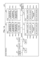
- FIG. 10 illustrates an example of whole processing for setting an SDP by a backup apparatus according to an embodiment
- FIG. 11 illustrates an example of a flow of SDP setting processing by a backup apparatus in an embodiment
- FIG. 12 illustrates an example of a flow of processing based on a policy by a backup apparatus in an embodiment
- FIG. 13 illustrates a flow of SDP transfer processing by a backup apparatus an embodiment
- FIG. 14 illustrates an example of a computer which executes a backup program according to an embodiment
- FIG. 15 illustrates a typical technique
- Embodiments of a backup apparatus, a backup method and a backup program embodied in a computer readable storage medium according to the present invention will be described below with reference to accompanying drawings.
- the outline of a backup apparatus according to an embodiment, a configuration of the backup apparatus and a flow of processing is described, and other embodiments will be described.
- the backup apparatus is provided with an addition-source area, for example an “addition-source area A”, set as a storage area permitted to be additionally assigned to a generation for which the capacity is to be increased.
- an addition-source area A set as a storage area permitted to be additionally assigned to a generation for which the capacity is to be increased.
- an addition-source detection section detects whether the capacity of an addition-source area is to be increased, in the backup apparatus according to an embodiment.
- the backup apparatus detects whether the capacity of an unassigned area, which is not assigned to any generation, is insufficient among areas within the “addition-source area A” in FIG. 1 .
- the unassigned area is illustrated as an area in gray, which is not assigned to a “generation 1 ” or a “generation 2 ” in FIG. 1 .
- a setting section sets an addition-source area in a free storage area which is not assigned to any generation.
- the setting section sets an “addition-source area B” in the free storage area.
- an addition-source area is set in a free storage area which is not assigned as a backup data storage area.
- the backup apparatus is capable of appropriately setting an addition-source area. For example, when the capacity of an addition-source area is insufficient, the apparatus can automatically set an addition-source area, unlike the technique in which it is required to wait until a user newly sets an addition-source area. As a result, it is possible to assign a new additional storage area without having to wait for setting of an addition-source area by the user.
- FIG. 1 a configuration of a backup apparatus 20 illustrated in FIG. 1 is described with the use of FIG. 2 .
- the backup apparatus 20 stores a snapshot, which is a copy-source volume (backup-source data) for a generation, into a storage area assigned to each of generations for which backup is to be executed.
- the backup apparatus 20 is, for example, an apparatus which executes SnapOPC or OPC.
- OPC is a backup technique for creating a snapshot, which is data at a predetermined time point, of data to be backed up.
- OPC is a technique for, backing up all the data of a target copy-source volume at the time point of the creation when creating a backup.
- SnapOPC is a technique for backing up only the data before update at a position within the data of a copy-source volume where the update has been performed, when creating a backup. That is, according to SnapOPC, it is possible to reduce the storage area required for backup because a copy-destination storage area is not used unless a copy-source volume is updated.
- the backup apparatus assigns an SDV (Snap Data Volume) with a predetermined storage capacity for each generation. If there is an SDV with an insufficient capacity, among the SDVs assigned to the generations, the backup apparatus adds an SDPE (Snap Data Pool Element), which is an additional storage area.
- the backup apparatus adds an SDPE using a storage area which has not been added yet within an SDP (Snap Data Pool), which is a storage area set by a user.
- the backup apparatus 20 is connected with a host 10 via a CA (Channel Adapter) 100 , and is provided with the CA 100 , a disk 200 and a CM (Centralized Module) 300 .
- CA Channel Adapter
- CM Centralized Module
- processing for the backup apparatus 20 to store a snapshot is similar to processing by SnapOPC or OPC, description thereof will be simplified or omitted.
- the host 10 is connected to the backup apparatus 20 via the CA 100 .
- the host 10 for example, is an apparatus used by an administrator who manages the backup apparatus 20 , which may be a computer terminal for example.
- the host 10 transmits, for example, an instruction to create a snapshot, an instruction to set an SDP from the administrator, an instruction to extend a copy-source volume, an instruction to add a copy-source volume, or the like to the backup apparatus 20 via the CA 100 .
- the CA 100 is connected to the host 10 and the CM 300 .
- the CA 100 is an I/F control section for the host 10 and the CM 300 , and it controls transmission/receiving of information between the host 10 and the CM 300 .
- the CA 100 controls processing for receiving an instruction for transmitting an instruction to create a snapshot, an instruction to set an SDP from the administrator, an instruction to extend a copy-source volume or an instruction to add a copy-source volume, from the host 10 and sending the processing to the CM 300 .
- the CA 100 also controls processing for transmitting a response to the instruction from the CM 300 to the host 10 .
- the disk 200 is connected to the CM 300 via a DA (Disk Adapter) 310 to be described later, and is a storage medium for storing data to be used for backup processing.
- the disk 200 is, for example, a disk device such as an HDD (Hard Disk Drive), a magneto-optical disk (MO disk) and a solid-state disk (SSD).
- the disk 200 may be any storage device for storing information, and is not limited to a storage device having a “disk”.
- the disk 200 is not limited to one storage device. It may have multiple storage devices. Description will be made below on the assumption that the disk 200 has multiple RAID groups, for example, RAID groups “A” to “E”.
- the disk 200 stores a copy-source volume and stores a snapshot.
- the backup apparatus 20 is not limited to the case where a copy-source volume is stored in the disk 200 .
- the backup apparatus 20 may be connected to a storage device in which a copy-source volume is stored, via a network.
- a copy-source volume is stored in the disk 200 by the administrator in advance.
- the disk 200 will be further described from a viewpoint that it stores a snapshot. For each of generations for which backup is to be executed, the disk 200 stores a snapshot created for a generation specified by an instruction, in a storage area assigned to the generation specified by the instruction. For example, the snapshot is stores into the disk 200 by an instruction from a control section 330 .
- the disk 200 is an SDV or an SDPE, which is a storage area set at an Logical Volume Number (LUN) in the disk 200 .
- LUN Logical Volume Number
- the LUN is identified by being given a number.
- the SDV is a storage area with a predetermined capacity which is assigned to a generation to obtain a backup of data at the time of starting executing backup.
- the SDV is a volume whose actual capacity (referred to as a “physical capacity” here) is less than the capacity identified by the host 10 (referred to as a “logical capacity” here), and it stores snapshot data corresponding to difference due to update.
- description is made on the assumption that an SDV is already assigned to each generation.
- the SDPE is a storage area to be added when the capacity of an SDV is in sufficient.
- the SDPE is a storage area with a predetermined capacity, which is assigned from an unassigned storage area within an SDP, and an addition-source area set as a storage area permitted to be additionally assigned. That is, the SDPE is assigned including for the purpose of avoiding data overflow when the capacity of an SDV is insufficient and all backup data for a corresponding generation is not stored in the SDV.
- the SDPE is assigned to each generation on a predetermined-capacity basis. For example, a capacity of “100M” is assigned.
- the backup apparatus 20 is not limited to the case where an SDPE is assigned on a predetermined-capacity basis. For example, an SDPE with any capacity may be assigned.
- the SDP is a storage area permitted to be used as an additional storage area.
- the SDP is set by a user, or is set by an SDP setting section 332 to be described in detail below.
- a storage area permitted to be used as an additional storage area (SDPV (Snap Data Pool Volume)) is set in a storage area within each RAID group.
- SDPV Sp Data Pool Volume
- FIG. 3 illustrates the SDV, the SDP and the SDPE in an embodiment.
- the backup apparatus 20 ( FIG. 2 ) stores backup data in an SDV assigned to a corresponding generation.
- the backup apparatus 20 stores the backup data into an SDPE assigned from the SDP as illustrated in ( 2 ) in FIG. 3 .
- “SDPV-A” illustrated in FIG. 3 is an SDPV set in a storage area in the RAID group “A”.
- a copy-source volume is stored in the disk 200
- a snapshot is stored in an SDV or an SDP set in the disk 200 .
- the storage areas existing in the disk 200 include not only the storage area in which a copy-source volume is stored and the areas set as an SDV and an SDPE but also a free storage area which is not assigned to any generation. In other words, the storage areas existing in the disk 200 also include a free storage area which is not assigned as an area for storing a copy-source volume or backup data.
- the CM 300 ( FIG. 2 ) is connected with the CA 100 and the disk 200 and is configured to execute various backup processings.
- the CM 300 is provided with the DA 310 , a storage section 320 and a control section 330 .
- the backup apparatus 20 is provided with one or multiple CMs 300 .
- Each of the CMs 300 is in charge of one or multiple disks 200 and performs processing for the disk 200 which the CM 300 is in charge of.
- the DA 310 is connected with the disk 200 and the control section 330 .
- the DA 310 is an I/F control section for the disk 200 and the control section 330 , and it controls transmission/receiving of information to and from the disk 200 .
- the DA 310 controls processing for storing or deleting snapshot data into or from the disk 200 and controls processing for reading a snapshot from the disk 200 , in accordance with an instruction from the control section 330 .
- the storage section 320 is connected with the control section 330 and stores data used for backup processing by the control section 330 .
- the storage section 320 is, for example, a cache. As illustrated in FIG. 2 , the storage section 320 is provided with an SDV management information storage section 321 , an SDP management information storage section 322 and an SDPE management information storage section 323 .
- the SDV management information storage section 321 is connected to an assignment section 331 to be described in detail below, the SDP setting section 332 and an SDP transfer section 334 to be described in detail below, and it stores SDV management information for managing an SDV assigned to each generation.
- the SDV management information storage section 321 stores “RAID group identification information”, “capacity used (resolution)”, “starting physical address” and “currently used LBA (Logical Block Address) in association with “generation information” identifying a generation.
- FIG. 4 is a diagram for illustrating the SDV management information storage section in an embodiment.
- generation information “the first generation SDV” indicates a generation “the first generation SDV”.
- the “RAID group identification information” is information identifying a RAID group.
- the RAID group identification information indicates a RAID group having a storage area assigned as an SDV.
- RAID group identification information “A” indicates the RAID group “A”.
- the “capacity used” indicates the capacity of a storage area (the capacity used in the disk 200 when the storage area is assigned).
- “capacity used” (resolution) indicates the capacity of a storage area assigned to an associated generation as an SDV.
- starting physical address is information uniquely identifying an area in a storage area.
- starting physical address indicates information identifying an area where a storage area assigned to an associated generation as an SDV starts.
- the “currently used LBA” indicates an address at which backup data is stored in a storage area.
- “currently used LBA” indicates an address indicating an area where backup data is stored, within a storage area assigned as an SDV.
- the backup data is all or a part of a snapshot.
- the SDV management information storage section 321 stores the RAID group identification information “A”, a capacity used “500M”, a starting address “ 200 ”, and currently used LBA's “ 200 , 210 , . . . ” in association with the generation information “the first generation SDV”. That is, the SDV management information storage section 321 stores that an area identified by the capacity used “500M” and the starting address “ 200 ”, within the storage area existing in the RAID group identification information “A”, has been assigned to the “first generation SDV” as an SDV.
- the SDV management information storage section 321 also stores information indicating that backup data is stored in a storage area identified by the currently used LBA's “ 200 , 210 , . . . ” within the SDV assigned to the “first generation SDV”.
- a technique for identifying a storage area using the RAID identification information, the capacity used and the starting address is described.
- the present invention is not limited thereto.
- a number of blocks from the starting address may be used instead of the capacity used.
- the number of blocks is the number of unit areas provided in a storage area.
- the SDV management information storage section 321 stores, for each generation, “addition of SDPE” indicating whether an SDPE has been added.
- the SDV management information storage section 321 stores “O” for “addition of SDPE” when an SDPE is added.
- “O” for “addition of SDPE” is stored in association with the generation information “the first generation SDV”.
- the “RAID group identification information”, “capacity used” (resolution) and “starting physical address” associated with each generation information are inputted by the assignment section 331 when an SDP is assigned.
- the currently used LBA is inputted by the control section 330 when data is stored into an SDV.
- the information stored in the SDV management information storage section 321 is used by the control section 330 or the SDP transfer section 334 .
- the SDP management information storage section 322 is connected to the assignment section 331 , the SDP setting section 332 and the SDP transfer section 334 , and it stores, for each RAID group, SDP management information for managing each SDPV set in the storage area in the RAID group.
- the SDP management information storage section 322 stores the “capacity used, the “starting physical address” and the “added LBA” as the SDP management information, in association with each “RAID group identification information”.
- FIG. 5 is a diagram for illustrating the SDP management information storage section in an embodiment.
- the “added LBA” is a storage area assigned as an SDPE within an SDP.
- the SDP management information storage section 322 stores the capacity used “500M”, the starting physical address “ 5000 ” and the added LBA “ 5000 to 5200 ” in association with the RAID group identification information “A”. That is, the SDP management information storage section 322 stores that an SDP is set for a storage area identified by the starting physical address “ 5000 ” and the capacity used “500M” in a RAID group identified by the RAID group identification information “A”. The SDP management information storage section 322 also stores information indicating that “ 5000 to 5200 ”, within the storage area for which the SDP is set, have already been assigned.
- the “RAID group identification information”, the “capacity used” and the “starting physical address” are inputted by the SDP setting section 332 or the administrator when an SDPV is set and used as an SDP.
- the “added LBA” is inputted by the assignment section 331 when an SDPE is assigned.
- the information stored in the SDP management information storage section 322 is used by the assignment section 331 and the SDP transfer section 334 .
- the SDPE management information storage section 323 is connected to the assignment section 331 and the SDP transfer section 334 .
- the SDPE management information storage section 323 stores, for each generation, SDPE management information for managing an SDPE assigned to the generation.
- the SDPE management information storage section 323 stores, for each RAID group identification information, the “capacity used”, the “starting physical address” and the “currently used LBA” in association with the “generation information”.
- the SDPE management information storage section 323 stores the generation information “the first generation SDV”, the capacity used “100M”, the starting physical address “ 5000 ” and the currently used LBA's “ 5010 , 5020 . . . ” in association with the RAID group identification information “A”. That is, the SDPE management information storage section 323 stores that a storage area identified by the capacity used “100M” and the starting address “ 5000 ”, within an SDPV set in the RAID group “A”, has been assigned to the generation “the first generation SDV” as an SDPE.
- the SDPE management information storage section 323 also stores information indicating that backup data is stored in a storage area identified by the currently used LBA's “ 5010 , 5020 , . . . ”.
- the “generation information”, “capacity used” and “starting physical address” associated with the RAID group identification information, among the information stored in the SDPE management information storage section 323 , are inputted by the assignment section 331 when the SDPE is assigned.
- the currently used LBA's, among the information stored in the SDPE management information storage section 323 are inputted by the control section 330 when backup data is stored into the SDPE.
- the control section 330 for example, has an internal memory for storing a program in which various backup processing procedure(s) and the like are specified and executes various backup processings.
- the control section 330 is provided with the assignment section 331 , the SDP setting section 332 , a policy operation section 333 and an SDP transfer section 334 .
- the control section When receiving an instruction to store a snapshot, from the host 10 via the CA 100 , the control section stores the snapshot into the disk 200 .
- the control section 330 refers to the SDV management information storage section 321 or the SDPE management information storage section 323 to identify an SDV or an SDPE to store the snapshot, and stores the snapshot therein if there is free space. Specifically, if “O” is specified for “addition of SDPE” in the SDV management information storage section 321 , the control section 330 acquires information identifying an SDPE to store the snapshot, from the SDPE management information storage section 323 and stores the snapshot therein.
- the control section 330 acquires information identifying an SDV to store the snapshot, from the SDV management information storage section 321 and stores the snapshot therein.
- the control section 330 also inputs information identifying the storage area in which the snapshot is stored as a currently used LBA in the SDV management information storage section 321 or the SDPE management information storage section 323 .
- control section 330 waits for an SDPE to be assigned by the assignment section 331 to be described in detail below, and stores the snapshot after an SDPE is assigned.
- the assignment section 331 is connected to the SDV management information storage section 321 , the SDP management information storage section 322 and the SDPE management information storage section 323 , and it assigns an SDV or an SDPE to each generation.
- the assignment section 331 when receiving an instruction to store a snapshot, from the host 10 via the CA 100 , the assignment section 331 detects whether the capacity of an assigned storage area is to be increased. If the assignment section 331 detects that the capacity is to be increased, the assignment section 331 assigns an SDPE. Each of the detection and the assignment will be described below.
- the detection by the assignment section 331 will be described.
- the case of detecting whether the capacity of an SDV is to be increased detecting the SDV of a generation for which the capacity is to be increased
- the assignment section 331 performs the detection using the “capacity used (resolution)”, “starting physical address” and “currently used LBA” stored in the SDV management information storage section 321 , for each of generations specified by an instruction.
- the assignment section 331 judges there is free space corresponding to the capacity of backup data to be stored, which is identified by an instruction to store a snapshot, received from the host 10 . If the free space does not exist, the assignment section 331 detects that the capacity is to be increased (it is necessary to increase the capacity).
- the assignment section 331 detects that the capacity is to be increased (it is necessary to increase the capacity). For example, for such a generation that the capacity corresponding to a rate (for example, 70%) set by the administrator in advance has been used, in other words, for the SDV of such a generation that the free space of the SDV reaches the rate set by the administrator in advance, the assignment section 331 detects that the capacity is to be increased (it is necessary to increase the capacity).
- a rate for example, 70%
- the assignment section 331 detects whether the capacity of an SDPE is to be increased, using the “capacity used (resolution)”, “starting physical address”, and “currently used LBA” stored in the SDVE management information storage section 320 for each generation. That is, for example, after assigning an SDPE because of shortage of the free space of an SDV, the assignment section 331 detects, for the SDPE, whether free space is insufficient.
- the assignment section 331 assigns an SDPE to the detected generation from an unassigned storage area in an SDP. That is, the assignment section 331 assigns an SDPE from an SDP to such an SDV or SDPE that the assigned storage area capacity is to be increased.
- the assignment section 331 refers to the SDP management information storage section 322 . Then, in association with generation information identifying a generation to which an SDPE is assigned, the assignment section 331 inputs the “RAID group identification” and “SDPE management information” about the SDPE assigned to the generation into the SDPE management information storage section 323 . The assignment section 331 also inputs the “RAID group identification” and “added LBA” in association with a storage area assigned as the SDPE, into the SDP management information storage section 322 . The assignment section 331 also inputs “O” for “addition of SDPE” in association with the generation information identifying the generation to which the SDPE is to be assigned, into the SDV management information storage section 321 .
- the assignment section 331 assigns a storage area identified by the capacity used “100M” and the starting address “ 5000 ”, within the storage area in the RAID group “A”, to the generation “the first generation SDV” as an SDPE.
- the assignment section 331 inputs the RAID group identification information “A”, the capacity used “100M” and the starting address “ 5000 ” in association with the generation information “the first generation SDV”, into the SDPE management information storage section 323 .
- the assignment section 331 inputs information identifying the storage area assigned as the SDPE within the SDP set in the RAID group “A”, in association with the RAID group identification information “A”, as an added LBA in the SDP management information storage section 322 .
- the assignment section 331 waits for an SDP to be set by the SDP setting section 332 to be described later, and assigns an SDPE after an SDP is set.
- the case where there is no storage area which is not assigned yet within the SDP is, for example, the case where the capacity of an unassigned area within an area set as an SDP is less than a predetermined capacity to be assigned as an SDPE (for example, the capacity used “100M”).
- the assignment section 331 If the assignment section 331 detects that the capacity of an SDV or an SDPE is to be increased (it is necessary to increase the capacity), the assignment section 331 sends, for example, information to the effect that there is a generation for which the capacity is to be increased (the SDV or SDPE of a generation for which the capacity is to be increased exists) to the SDP setting section 332 .
- the SDP setting section 332 is connected to the DA 310 , the SDV management information storage section 321 , the SDP management information storage section 322 , the assignment section 331 and the policy operation section 333 , and it sets an SDP without accepting an instruction from a user.
- the SDP setting section 332 sets an SDP without accepting an instruction from a user. Specifically, the SDP setting section 332 detects whether the capacity of an SDP is to be increased, judges whether there is free space, and sets an SDP. Each of the detection, the judgment and the setting is described in detail below.
- the SDP setting section 332 detects whether the capacity of an SDP is to be increased. For example, the SDP setting section 332 detects whether the capacity of the SDP is to be increased using the “capacity used” (resolution), “starting physical address” and “added LBA” stored in the SDP management information storage section 322 .
- the SDP setting section 332 detects such a generation that the capacity of the SDP is insufficient, in other words, the state that the capacity of an unassigned storage area within an SDP is insufficient so that an SDPE cannot be assigned, as the state that the capacity of the SDP is to be increased (it is necessary to increase the capacity). For example, if the capacity of the unassigned storage area within an SDP is less than a predetermined capacity assigned as an SDPE, the SDP setting section 332 detects that the capacity of the SDP is to be increased.
- the SDP setting section 332 detects a state that the capacity of an unassigned storage area within an SDP reaches the capacity indicated by a threshold set by the administrator in advance as the state that the capacity of the SDP is to be increased. In other words, the SDP setting section 332 detects the state that an SDPE corresponding to the capacity indicated by the threshold is assigned from an SDP as the state that the capacity of the SDP is to be increased.
- the SDP setting section 332 detects, for example, a state that an SDPE corresponding to a rate set by the administrator in advance (for example, 70%) is assigned from an SDP as the state that the capacity of the SDP is to be increased. In other words, the SDP setting section 332 detects the state that the capacity of an unassigned storage area within an SDP reaches a rate set by the administrator in advance as the state that the capacity of the SDP is to be increased.
- the SDP setting section 332 judges whether there is a free storage area for which setting of an SDP can be permitted. For example, the SDP setting section 332 identifies a storage area for which a copy-source volume, an SDV or an SDP is not set, within the storage area in the disk 200 , using the SDV management information storage section 321 or the SDP management information storage section 322 . That is, the SDP setting section 332 identifies a free storage area which is not assigned as an area for storing a copy-source volume or backup data.
- the SDP setting section 332 judges whether a capacity of the storage area for which an SDV or an SDP is not set has a capacity enough to set an SDP. For example, if the free space of the identified storage area is equal to or above a predetermined capacity to be assigned as an SDPE, the SDP setting section 332 judges that there is a sufficient capacity, and otherwise, it judges that there is no sufficient capacity.
- FIG. 7 is a diagram for illustrating the SDP setting section in an embodiment.
- the SDP setting section 332 sets an SDPV-E as illustrated in ( 2 ) in FIG. 7 in a free space in a storage area in a RAID group “E” illustrated in ( 1 ) in FIG. 7 , and uses the SDPV-E as an SDP as illustrated in ( 3 ) in FIG. 7 .
- “LUN- 1 ” to “LUN- 3 ” illustrated in FIG. 7 are data stored in storage areas in the RAID group “E”.
- the SDP setting section 332 inputs the “RAID group identification information”, the “capacity used” and the “starting physical address” as information identifying the set SDP, into the SDP management information storage section 322 . If the SDP setting section 332 judges that there is no free space, the SDP setting section 332 sends information to that effect, to the policy operation section 333 .
- the SDP setting section 332 inputs a value whose upper limit is the capacity of the free space in the RAID group, as the “capacity used”. For example, the SDP setting section 332 inputs the upper limit of the free space in the RAID group as the capacity used, or inputs the capacity corresponding to a predetermined rate of the free space in the RAID group.
- the SDP setting section 332 inputs the capacity used “500M” and the starting address “ 200 ” in association with the RAID group identification information “E”, into the SDP management information storage section 322 . That is, an SDPV is newly set in the RAID group “E” and used as an SDP.
- the SDP setting section 332 determines one RAID group and sets an SDPV in the determined RAID group.
- an RAID group having the largest free space is determined among the RAID groups having free space.
- the policy operation section 333 is connected to the DA 310 and the SDP setting section 332 .
- the policy operation section 333 performs processing based on a policy set in advance for the purpose of avoiding shortage of the storage area for storing a snapshot. For example, as illustrated in FIG. 8 , the policy operation section 333 uses “Mail Send”, “Delete Oldest Session”, “Write Protect” or the like, as a policy.
- FIG. 8 illustrates an example of policies used by the policy operation section in an embodiment.
- the policy operation section 333 informs the administrator to the effect that it has been judged that there is no free storage area. Furthermore, for example, in the case of using “Delete Oldest Session”, the policy operation section 333 sequentially deletes snapshots stored in a storage area beginning with the snapshot for the oldest generation until the capacity is a predetermined capacity. For example, in the case of using “Write Protect”, the policy operation section 333 prohibits a snapshot from being stored after it is judged that there is no free storage area.
- the policy operation section 333 executes processing based on one or multiple policies specified by the administrator in advance. Since an example of detailed processing by the policy operation section 333 will be described later, description thereof will be omitted here.
- the SDP transfer section 334 is connected to the SDV management information storage section 321 , the SDP management information storage section 322 , the SDPE management information storage section 323 and the DA 310 .
- the SDP transfer section 334 detects, for a storage area in any RAID group among multiple RAID groups, whether the storage area has a predetermined free storage area capacity.
- the SDP transfer section 334 detects whether there is free space enough to set “LUN- 4 ” in an area other than “LUN- 1 ” to “LUN- 3 ”, for which an SDP or an SDV is not set, in the RAID group “E”. If there is no sufficient free space, the SDP transfer section 334 detects that the predetermined free storage area capacity is not secured.
- the SDP transfer section 334 detects whether there is a storage area corresponding to the capacity to be extended in an area other than “LUN- 1 ” to “LUN- 3 ”, for which an SDP or an SDV is not set, in the RAID group “E”. If there is no sufficient free space, the SDP transfer section 334 detects that the predetermined free storage area capacity is not secured.
- the SDP transfer section 334 transfers an SDP set for a storage area in the target RAID group, which is the RAID group detected not to have the predetermined free storage area capacity, to another RAID group. Specifically, the SDP transfer section 334 transfers the SDP to a free storage area which is not assigned to any generation within the storage area in a RAID group different from the target RAID group. In other words, the SDP transfer section 334 transfers the SDP to a free storage area which is not assigned as an area for storing a copy-source volume and backup data.
- the SDP transfer section 334 distributes and transfers the SDP to storage areas in multiple different RAID groups.
- FIG. 9 is a diagram for illustrating the SDP transfer section in an embodiment. Because there is no free space enough to set “LUN- 4 ”, the SDP transfer section 334 detects that the capacity is to be increased (it is necessary to increase the capacity). Then, for example, the SDP transfer section 334 transfers the SDP in the RAID group “E” to a free storage area within the storage area in the RAID group “F” and a free storage area among the storage areas in the RAID group “G”.
- the SDP transfer section 334 distributes and transfers the SDP in SDPE. That is, in the example illustrated in FIG. 9 , three SDPEs are transferred to the RAID group “F”, and two SDPEs are transferred to the RAID group “G”.
- the SDP transfer section 334 does not perform data transfer and only makes settings as an SDP.
- the present invention is not limited to the case where the SDP transfer section 334 transfers all SDPs. It is also possible to transfer only a part of the SDPs. For example, in a case illustrated in FIG. 9 , it is possible to transfer only three of the five SDPEs and leave the remaining two as they are set in the RAID group “E”.
- the control section 330 when receiving an instruction to store a snapshot (operation S 101 ), the control section 330 refers to the SDV management information storage section 321 or the SDPE management information storage section 323 (operation S 102 ). That is, the control section 330 identifies an SDV or an SDPE for storing the snapshot.
- control section 330 when determining there is free space (operation S 103 : YES), the control section 330 stores the snapshot (operation S 104 ). On the other hand, when determining there is no free space (operation S 103 : NO), the control section 330 waits for an SDPE to be assigned by the assignment section 331 , and stores the snapshot after an SDPE is assigned (operation S 104 ).
- the assignment section 331 when receiving an instruction to store a snapshot (operation S 201 ), the assignment section 331 detects whether a capacity of an SDV or an SDPE is to be increased (operation S 202 ). If detecting that the capacity of an SDV or an SDPE is to be increased (it is necessary to increase the capacity) (operation S 202 : YES), the assignment section 331 sends information to the effect that there is a generation for which the capacity is to be increased (the SDV or SDPE of a generation for which the capacity is to be increased exists) to the SDP setting section 332 (operation S 203 ).
- the assignment section 331 assigns an SDPE (operation S 205 ).
- the assignment section 331 waits for an SDP to be set by the SDP setting section 332 , and assigns an SDPE after an SDP is set (operation S 205 ). If the assignment section 331 does not detect that the capacity of an SDV or an SDPE is to be increased (it is necessary to increase the capacity) (operation S 202 : NO), it ends the processing.
- the SDP setting section 332 receives information to the effect that there is a generation for which the capacity is to be increased, from the assignment section 331 (operation S 301 ). Then, the SDP setting section 332 detects whether or not to increase the capacity of an SDP (operation S 302 ).
- the SDP setting section 332 detects that the capacity of the SDV is to be increased (it is necessary to increase the capacity) (operation S 302 : YES)
- the SDP setting section 332 sets an SDP (operation S 304 ) when determining there is a free storage area which is not assigned to any generation (operation S 303 : YES).
- the SDP setting section 332 sends information to the effect that there is no free storage area, to the policy operation section 333 . If the SDP setting section 332 does not detect that the capacity of the SDP is to be increased (operation S 302 : NO), the SDP setting section 332 ends the processing.
- the policy operation section 333 receives information to the effect that there is no free storage area, from the SDP setting section 332 (operation S 401 ). Then, the policy operation section 333 executes processing based on a policy (operation S 402 ).
- FIG. 11 illustrates an example of the flow of the SDP setting processing by the backup apparatus in an embodiment.
- FIG. 11 the processing by the SDP setting section 332 described with reference to FIG. 10 will be described in detail.
- the SDP setting section 332 when receiving information to the effect that there is a generation for which the capacity is to be increased (operation S 501 : YES), that is, when receiving information to the effect that it has been detected that the capacity of an SDV or an SDPE is to be increased, the SDP setting section 332 detects whether the SDP is insufficient (operation S 502 ). That is, the SDP setting section 332 detects whether the capacity of the SDP is to be increased.
- the SDP setting section 332 judges whether there is a free storage area in the RAID groups (operation S 503 ). That is, the SDP setting section 332 judges whether or not there is a free storage area for which setting of an SDP is permitted, in the disk 200 .
- the SDP setting section 332 judges whether there is a free storage area for setting an SDP in each of the multiple RAID groups (operation S 504 ). If there is a free storage area for setting an SDP in each of the multiple RAID groups (operation S 504 : YES), the SDP setting section 332 determines one RAID group (operation S 505 ) and sets an SDP (operation S 506 ). That is, an SDPV is set in the determined RAID group and used as an SDP. If there is no free storage area for setting an SDP in each of the multiple RAID groups (operation S 504 : NO), the SDP setting section 332 sets an SDP in one RAID group having free space (operation S 506 ).
- operation S 502 determines whether the SDP is sufficient. If it is judged at the operation S 502 that the SDP is sufficient (operation S 502 : NO), the processing is ended. If it is judged at the above operation S 503 that there is no free storage area (operation S 503 : NO), the processing sends information to the effect that there is no free storage area, to the policy operation section 333 (operation S 507 ), and the processing is ended.
- FIG. 12 description will be made on the case where an instruction to update a copy-source volume is issued from the administrator when the control section 330 stores a snapshot into a storage area, and an SDV or an SDP is insufficient then.
- the policy operation section 333 judges whether the policy “Mail Send” is set (operation S 602 ). That is, the policy operation section 333 judges whether the administrator sets that the policy “Mail Send” is to be used. If judging that the policy “Mail Send” is set (operation S 602 : YES), the policy operation section 333 informs the administrator of information to the effect that there is no sufficient capacity by mail (operation S 603 ).
- the policy operation section 333 judges whether the policy “Delete Oldest Session” is set (operation S 604 ). That is, the policy operation section 333 judges whether the administrator sets that the policy “Delete Oldest Session” is to be used. If judging that the policy “Delete Oldest Session” is set (operation S 604 : YES), the policy operation section 333 deletes the oldest snapshot (operation S 605 ), and judges whether a free storage area with a predetermined capacity is secured (operation S 606 ).
- the policy operation section 333 judges that no free area with a predetermined capacity is secured (operation S 606 : NO), the policy operation section 333 repeats the processings of operations S 605 and S 606 until it judges that a free area with the predetermined capacity is secured.
- control section 330 After that, for example, by the SDP setting section 332 setting an SDP in a secured free storage area and the assignment section 331 assigning an SDPE, the control section 330 stores a snapshot into the storage area (operation S 607 ), and the copy-source volume is updated (operation S 608 ).
- the policy operation section 333 judges whether the policy “Write Protect” is set (operation S 609 : YES). That is, the policy operation section 333 judges whether the administrator sets that the policy “Write Protect” is to be used.
- the policy operation section 333 disables writing (operation S 610 ). That is, storage of a snapshot is disabled after it is judged that there is no free storage area.
- FIG. 13 is a flowchart for illustrating a flow of the SDP transfer processing by the backup apparatus in an embodiment.
- the SDP transfer section 334 When receiving an instruction to newly create or extend an LUN from the administrator (operation S 701 : YES), the SDP transfer section 334 , for example, detects whether there is free space (operation S 702 ). That is, the SDP transfer section 334 detects whether a predetermined free storage area capacity is secured. When detecting that there is no free space (operation S 702 : NO), that is, detecting that the predetermined free storage area capacity is not secured, the SDP transfer section 334 detects whether an SDP is set for a storage area in a target RAID group (operation S 703 ).
- the SDP transfer section 334 detects whether there is free space equal to or larger than the capacity of the set SDP in a different RAID group (operation S 704 ).
- operation S 701 determines there is no newly created LUN (operation S 701 : NO)
- the process continues the detection until there is a newly created LUN.
- the SDP transfer section 334 transfers the SDP (operation S 705 ). That is, the SDP transfer section 334 transfers the SDP to a free storage area which is not assigned to any generation, within the storage area in the RAID group different from the target RAID group. After that, a LUN is newly created or extended in a free area generated by the SDP having been transferred by the SDP transfer section 334 (operation S 706 ). Similarly, in the case where it is detected at the above operation S 702 that there is free space (operation S 702 : YES) also, a LUN is newly created or extended (operation S 706 ).
- an SDPE is assigned to the SDV or SDPE the capacity of which is to be increased, from an SDP. Furthermore, it is detected whether to increase the capacity of the SDP. If it is detected that the capacity of the SDP is to be increased, the SDP is set in a free storage area which is not assigned to any generation. Thus, it is possible to appropriately set an SDP.
- the apparatus can automatically set an additional storage area, unlike the technique in which it is necessary to wait a user to newly set the storage area. As a result, it is possible to newly assign an additional storage area without waiting for setting by the user.
- an SDP set for a storage area in the target storage device is transferred. Specifically, since the SDP is transferred to a free storage area which is not assigned to any generation, within a storage area in a storage device different from the target storage device, it is possible to increase the free space in the target storage device.
- an addition-source area set in a storage area in a target storage device is distributed and transferred to storage areas in one or multiple different storage devices, it is possible to transfer the addition-source area, for example, even in the case where the addition-source area cannot be transferred to one different storage device.
- the present invention is not limited thereto, and it can be practiced using a different backup technique.
- OPC by encrypting backup data, an amount of data backed up differs among generations. Therefore, in the case of using an additional storage area, the technique for setting an additional storage area which has been described in an embodiment may be implemented for the OPC.
- the present invention is not limited thereto, and an SDV in a target storage device may be transferred.
- the present invention is not limited thereto.
- One or more methods among (1) to (3) may be implemented in addition to the technique for automatically setting an SDP.
- the technique of (2) is implemented in combination with the technique of (1).
- all or a part of processing which has been described to be automatically performed can be manually performed.
- the processing based on a policy may be manually performed.
- each component of each device shown in the figures is illustrated from a viewpoint of a functional concept, and it is not necessarily required to be physically configured as illustrated in the figures. That is, the concrete form of distribution/integration of each device is not necessarily limited to that illustrated in the figures.
- Each device can be configured by functionally or physically distributing/integrating all or a part thereof in any units according to various loads or use states. For example, to describe this with reference to FIG. 2 , the disk 200 may be distributedly arranged and connected via a network.
- a backup apparatus 3000 in an embodiment is provided with an operation section 3001 , a microphone 3002 , a speaker 3003 , a disk 3004 , a display 3005 , a communication section 3006 and a CPU (Central Processing Unit) 3010 .
- the backup apparatus 3000 is further provided with a ROM (Read-Only Memory) 3011 , an HDD (Hard Disk Drive) 3012 and a RAM (Random Access Memory) 3013 .
- the backup apparatus 3000 is configured by connecting the operation section 3001 , the microphone 3002 , the speaker 3003 , the disk 3004 , the display 3005 , the communication section 3006 , the CPU 3010 , the ROM 3011 , the HDD 3012 and the RAM 3013 via a bus 3009 or the like.
- the disk 3004 corresponds to the disk 200 in FIG. 2 .
- ROM 3011 there are stored in advance control programs which illustrate function(s) similar to those of the assignment section 331 , the SDP setting section 332 , the policy operation section 333 and the SDP transfer section 334 shown in an embodiment described above, that is, an assignment program 3011 a , an SDP setting program 3011 b , a policy operation program 3011 c and an SDP transfer program 3011 d as illustrated in FIG. 14 .
- These programs 3011 a to 3011 d may be appropriately integrated or separated similarly to each component of the backup apparatus illustrated in FIG. 2 .
- the programs 3011 a to 3011 d function as an assignment process 3010 a , an SDP setting process 3010 b , a policy operation process 3010 c and an SDP transfer process 3010 d , respectively, as illustrated in FIG. 14 .
- the processes 3010 a to 3010 d correspond to the assignment section 331 , the SDP setting section 332 , the policy operation section 333 and the SDP transfer section 334 illustrated in FIG. 2 , respectively.
- an SDV management information table 3012 a there are provided an SDV management information table 3012 a , an SDP management information table 3012 b and an SDPE management information table 3012 c .
- the tables 3012 a to 3012 c correspond to the SDV management information storage section 321 , the SDP management information storage section 322 and the SDPE management information storage section 323 illustrated in FIG. 2 , respectively.
- the CPU 3010 reads the SDV management information table 3012 a , the SDP management information table 3012 b and the SDPE management information table 3012 c and stores them into the RAM 3013 , and executes the backup program using SDV management information data 3013 a , SDP management information data 3013 b , SDPE management information data 3013 c and policy information data 3013 d stored in the RAM 3013 .
- the program can be distributed via a network such as the Internet. It is also possible to record the program in a computer-readable recording medium such as a hard disk, a flexible disk (FD), a CD-ROM, an MO and a DVD and execute them by reading them from the recording medium by a computer.
- a computer-readable recording medium such as a hard disk, a flexible disk (FD), a CD-ROM, an MO and a DVD
- the embodiments can be implemented in computing hardware (computing apparatus) and/or software, such as (in a non-limiting example) any computer that can store, retrieve, process and/or output data and/or communicate with other computers.
- the results produced can be displayed on a display of the computing hardware.
- a program/software implementing the embodiments may be recorded on computer-readable media comprising computer-readable recording media.
- the program/software implementing the embodiments may also be transmitted over transmission communication media.
- Examples of the computer-readable recording media include a magnetic recording apparatus, an optical disk, a magneto-optical disk, and/or a semiconductor memory (for example, RAM, ROM, etc.).
- Examples of the magnetic recording apparatus include a hard disk device (HDD), a flexible disk (FD), and a magnetic tape (MT).
- optical disk examples include a DVD (Digital Versatile Disc), a DVD-RAM, a CD-ROM (Compact Disc-Read Only Memory), and a CD-R (Recordable)/RW.
- communication media includes a carrier-wave signal.
Abstract
Description
Claims (8)
Applications Claiming Priority (2)
| Application Number | Priority Date | Filing Date | Title |
|---|---|---|---|
| JP2008220423A JP4893716B2 (en) | 2008-08-28 | 2008-08-28 | Backup device, backup method and backup program |
| JP2008-220423 | 2008-08-28 |
Publications (2)
| Publication Number | Publication Date |
|---|---|
| US20100058015A1 US20100058015A1 (en) | 2010-03-04 |
| US8756386B2 true US8756386B2 (en) | 2014-06-17 |
Family
ID=41727012
Family Applications (1)
| Application Number | Title | Priority Date | Filing Date |
|---|---|---|---|
| US12/546,243 Active 2031-08-16 US8756386B2 (en) | 2008-08-28 | 2009-08-24 | Backup apparatus, backup method and computer readable medium having a backup program |
Country Status (2)
| Country | Link |
|---|---|
| US (1) | US8756386B2 (en) |
| JP (1) | JP4893716B2 (en) |
Cited By (2)
| Publication number | Priority date | Publication date | Assignee | Title |
|---|---|---|---|---|
| US9323760B1 (en) * | 2013-03-15 | 2016-04-26 | Emc Corporation | Intelligent snapshot based backups |
| US11403026B2 (en) * | 2020-11-06 | 2022-08-02 | EMC IP Holding Company LLC | Method, device and computer program product for managing storage system |
Families Citing this family (6)
| Publication number | Priority date | Publication date | Assignee | Title |
|---|---|---|---|---|
| JP5106045B2 (en) * | 2007-10-30 | 2012-12-26 | 株式会社日立製作所 | Search engine linkage file sharing system |
| US8886904B2 (en) * | 2011-04-14 | 2014-11-11 | Kaminario Technologies Ltd. | Managing a solid-state storage device |
| US9367439B2 (en) * | 2012-04-30 | 2016-06-14 | Oracle International Corporation | Physical memory usage prediction |
| US8856484B2 (en) * | 2012-08-14 | 2014-10-07 | Infinidat Ltd. | Mass storage system and methods of controlling resources thereof |
| CN105487810B (en) * | 2014-09-18 | 2018-04-03 | 先智云端数据股份有限公司 | For reaching the system of non interference data reconstruction |
| US10402108B2 (en) * | 2017-01-20 | 2019-09-03 | Fujitsu Limited | Efficient control of data storage areas based on a size of compressed data to be written |
Citations (10)
| Publication number | Priority date | Publication date | Assignee | Title |
|---|---|---|---|---|
| WO2003102823A1 (en) | 2002-05-31 | 2003-12-11 | Fujitsu It Holdings, Inc. | Method and system for intelligent storage management |
| US20040254964A1 (en) * | 2003-06-12 | 2004-12-16 | Shoji Kodama | Data replication with rollback |
| US20050086445A1 (en) * | 2003-10-20 | 2005-04-21 | Yoichi Mizuno | Storage system and method for backup |
| US20060031637A1 (en) | 2004-08-03 | 2006-02-09 | Hitachi, Ltd. | Disk array device group and copy method for the same |
| US20060075200A1 (en) | 2004-10-06 | 2006-04-06 | Ai Satoyama | Snapshot system |
| JP2006099748A (en) | 2004-08-30 | 2006-04-13 | Hitachi Ltd | Storage system and data relocation controller |
| US20060143418A1 (en) | 2004-08-30 | 2006-06-29 | Toru Takahashi | Storage system and data relocation control device |
| US20060242378A1 (en) | 2005-04-21 | 2006-10-26 | Yoshiki Kano | System and method for managing disk space in a thin-provisioned storage subsystem |
| US20070271429A1 (en) | 2006-05-18 | 2007-11-22 | Hitachi, Ltd. | Storage System and method of producing recovery volume |
| US20080104350A1 (en) | 2006-10-30 | 2008-05-01 | Tomoto Shimizu | relocation system and a relocation method |
Family Cites Families (1)
| Publication number | Priority date | Publication date | Assignee | Title |
|---|---|---|---|---|
| JP4699808B2 (en) * | 2005-06-02 | 2011-06-15 | 株式会社日立製作所 | Storage system and configuration change method |
-
2008
- 2008-08-28 JP JP2008220423A patent/JP4893716B2/en active Active
-
2009
- 2009-08-24 US US12/546,243 patent/US8756386B2/en active Active
Patent Citations (17)
| Publication number | Priority date | Publication date | Assignee | Title |
|---|---|---|---|---|
| WO2003102823A1 (en) | 2002-05-31 | 2003-12-11 | Fujitsu It Holdings, Inc. | Method and system for intelligent storage management |
| JP2005535008A (en) | 2002-05-31 | 2005-11-17 | フジツウ アイティー ホールディングス,インコーポレイティド | Intelligent storage device management method and system |
| US20040254964A1 (en) * | 2003-06-12 | 2004-12-16 | Shoji Kodama | Data replication with rollback |
| US20050086445A1 (en) * | 2003-10-20 | 2005-04-21 | Yoichi Mizuno | Storage system and method for backup |
| US20060031637A1 (en) | 2004-08-03 | 2006-02-09 | Hitachi, Ltd. | Disk array device group and copy method for the same |
| JP2006048300A (en) | 2004-08-03 | 2006-02-16 | Hitachi Ltd | Disk array device group and its copy processing method |
| US20060143418A1 (en) | 2004-08-30 | 2006-06-29 | Toru Takahashi | Storage system and data relocation control device |
| JP2006099748A (en) | 2004-08-30 | 2006-04-13 | Hitachi Ltd | Storage system and data relocation controller |
| JP2006107162A (en) | 2004-10-06 | 2006-04-20 | Hitachi Ltd | Storage system |
| US20060075200A1 (en) | 2004-10-06 | 2006-04-06 | Ai Satoyama | Snapshot system |
| US20060242378A1 (en) | 2005-04-21 | 2006-10-26 | Yoshiki Kano | System and method for managing disk space in a thin-provisioned storage subsystem |
| JP2006302258A (en) | 2005-04-21 | 2006-11-02 | Hitachi Ltd | System and method for managing disk space in thin-provisioned storage subsystem |
| US20090157956A1 (en) * | 2005-04-21 | 2009-06-18 | Yoshiki Kano | System and method for managing disk space in a thin-provisioned storage subsystem |
| US20070271429A1 (en) | 2006-05-18 | 2007-11-22 | Hitachi, Ltd. | Storage System and method of producing recovery volume |
| JP2007310631A (en) | 2006-05-18 | 2007-11-29 | Hitachi Ltd | Storage system and method for creating its recovery volume |
| US20080104350A1 (en) | 2006-10-30 | 2008-05-01 | Tomoto Shimizu | relocation system and a relocation method |
| JP2008112276A (en) | 2006-10-30 | 2008-05-15 | Hitachi Ltd | Relocation system and relocation method |
Cited By (2)
| Publication number | Priority date | Publication date | Assignee | Title |
|---|---|---|---|---|
| US9323760B1 (en) * | 2013-03-15 | 2016-04-26 | Emc Corporation | Intelligent snapshot based backups |
| US11403026B2 (en) * | 2020-11-06 | 2022-08-02 | EMC IP Holding Company LLC | Method, device and computer program product for managing storage system |
Also Published As
| Publication number | Publication date |
|---|---|
| US20100058015A1 (en) | 2010-03-04 |
| JP2010055420A (en) | 2010-03-11 |
| JP4893716B2 (en) | 2012-03-07 |
Similar Documents
| Publication | Publication Date | Title |
|---|---|---|
| US8756386B2 (en) | Backup apparatus, backup method and computer readable medium having a backup program | |
| US10956063B2 (en) | Virtual storage system | |
| US8015381B2 (en) | Computer system, data migration monitoring method and data migration monitoring program | |
| JP4220724B2 (en) | Storage device | |
| US9361034B2 (en) | Transferring storage resources between snapshot storage pools and volume storage pools in a distributed network | |
| US7174438B2 (en) | Disk array apparatus | |
| US8627038B2 (en) | Storage controller and storage control method | |
| US9501231B2 (en) | Storage system and storage control method | |
| JP4990066B2 (en) | A storage system with a function to change the data storage method using a pair of logical volumes | |
| JP4684864B2 (en) | Storage device system and storage control method | |
| US7343465B2 (en) | Storage system | |
| US20090300283A1 (en) | Method and apparatus for dissolving hot spots in storage systems | |
| US8639898B2 (en) | Storage apparatus and data copy method | |
| US20080184000A1 (en) | Storage module and capacity pool free capacity adjustment method | |
| US8650381B2 (en) | Storage system using real data storage area dynamic allocation method | |
| US8386707B2 (en) | Virtual disk management program, storage device management program, multinode storage system, and virtual disk managing method | |
| WO2010103569A1 (en) | Storage system and control method for the same, and program | |
| US20110283062A1 (en) | Storage apparatus and data retaining method for storage apparatus | |
| US20120297156A1 (en) | Storage system and controlling method of the same | |
| JP6511795B2 (en) | STORAGE MANAGEMENT DEVICE, STORAGE MANAGEMENT METHOD, STORAGE MANAGEMENT PROGRAM, AND STORAGE SYSTEM | |
| JP2016162397A (en) | Storage control device, control system and control program | |
| US20100235599A1 (en) | Access control device, storage system, and access control method | |
| US7707199B2 (en) | Method and system for integrated management computer setting access rights, calculates requested storage capacity of multiple logical storage apparatus for migration | |
| US20100223442A1 (en) | Computer system and data erasing method | |
| US20110161607A1 (en) | Storage system and control method therefor |
Legal Events
| Date | Code | Title | Description |
|---|---|---|---|
| AS | Assignment |
Owner name: FUJITSU LIMITED,JAPAN Free format text: ASSIGNMENT OF ASSIGNORS INTEREST;ASSIGNOR:TOKOTO, HIROTOMO;REEL/FRAME:023153/0174 Effective date: 20090805 Owner name: FUJITSU LIMITED, JAPAN Free format text: ASSIGNMENT OF ASSIGNORS INTEREST;ASSIGNOR:TOKOTO, HIROTOMO;REEL/FRAME:023153/0174 Effective date: 20090805 |
|
| AS | Assignment |
Owner name: FUJITSU LIMITED, JAPAN Free format text: CORRECTIVE ASSIGNMENT TO CORRECT INVENTORS NAME TO SPECIFY HIROTOMO TOKORO WHICH WAS PREVIOUSLY RECORDED AT REEL 023153, FRAME 0174 ON AUGUST 25, 2009;ASSIGNOR:TOKORO, HIROTOMO;REEL/FRAME:025076/0030 Effective date: 20090805 |
|
| STCF | Information on status: patent grant |
Free format text: PATENTED CASE |
|
| MAFP | Maintenance fee payment |
Free format text: PAYMENT OF MAINTENANCE FEE, 4TH YEAR, LARGE ENTITY (ORIGINAL EVENT CODE: M1551) Year of fee payment: 4 |
|
| MAFP | Maintenance fee payment |
Free format text: PAYMENT OF MAINTENANCE FEE, 8TH YEAR, LARGE ENTITY (ORIGINAL EVENT CODE: M1552); ENTITY STATUS OF PATENT OWNER: LARGE ENTITY Year of fee payment: 8 |