US8769597B2 - Amplifier with noise reduction - Google Patents
Amplifier with noise reduction Download PDFInfo
- Publication number
- US8769597B2 US8769597B2 US12/778,941 US77894110A US8769597B2 US 8769597 B2 US8769597 B2 US 8769597B2 US 77894110 A US77894110 A US 77894110A US 8769597 B2 US8769597 B2 US 8769597B2
- Authority
- US
- United States
- Prior art keywords
- switch
- signal
- state
- coupled
- diplex filter
- Prior art date
- Legal status (The legal status is an assumption and is not a legal conclusion. Google has not performed a legal analysis and makes no representation as to the accuracy of the status listed.)
- Active, expires
Links
Images


Classifications
-
- H—ELECTRICITY
- H04—ELECTRIC COMMUNICATION TECHNIQUE
- H04L—TRANSMISSION OF DIGITAL INFORMATION, e.g. TELEGRAPHIC COMMUNICATION
- H04L12/00—Data switching networks
- H04L12/28—Data switching networks characterised by path configuration, e.g. LAN [Local Area Networks] or WAN [Wide Area Networks]
- H04L12/2801—Broadband local area networks
-
- H—ELECTRICITY
- H04—ELECTRIC COMMUNICATION TECHNIQUE
- H04L—TRANSMISSION OF DIGITAL INFORMATION, e.g. TELEGRAPHIC COMMUNICATION
- H04L12/00—Data switching networks
- H04L12/28—Data switching networks characterised by path configuration, e.g. LAN [Local Area Networks] or WAN [Wide Area Networks]
- H04L12/2854—Wide area networks, e.g. public data networks
- H04L12/2856—Access arrangements, e.g. Internet access
- H04L12/2858—Access network architectures
- H04L12/2861—Point-to-multipoint connection from the data network to the subscribers
-
- H—ELECTRICITY
- H04—ELECTRIC COMMUNICATION TECHNIQUE
- H04L—TRANSMISSION OF DIGITAL INFORMATION, e.g. TELEGRAPHIC COMMUNICATION
- H04L12/00—Data switching networks
- H04L12/28—Data switching networks characterised by path configuration, e.g. LAN [Local Area Networks] or WAN [Wide Area Networks]
- H04L12/2854—Wide area networks, e.g. public data networks
- H04L12/2856—Access arrangements, e.g. Internet access
- H04L12/2869—Operational details of access network equipments
- H04L12/2878—Access multiplexer, e.g. DSLAM
- H04L12/2892—Access multiplexer, e.g. DSLAM characterised by the access multiplexer architecture
- H04L12/2894—Centralized processing
-
- H—ELECTRICITY
- H04—ELECTRIC COMMUNICATION TECHNIQUE
- H04N—PICTORIAL COMMUNICATION, e.g. TELEVISION
- H04N7/00—Television systems
- H04N7/10—Adaptations for transmission by electrical cable
- H04N7/102—Circuits therefor, e.g. noise reducers, equalisers, amplifiers
-
- H—ELECTRICITY
- H04—ELECTRIC COMMUNICATION TECHNIQUE
- H04N—PICTORIAL COMMUNICATION, e.g. TELEVISION
- H04N7/00—Television systems
- H04N7/10—Adaptations for transmission by electrical cable
- H04N7/102—Circuits therefor, e.g. noise reducers, equalisers, amplifiers
- H04N7/104—Switchers or splitters
Definitions
- the present invention relates to amplifiers with noise reduction. More particularly, the present invention helps improve return path signal quality of video, voice, and data communications in a CATV (cable television) network such as HFC (Hybrid Fiber-Coaxial) network architectures used by CATV service providers, thereby allowing for longer transmission distances, higher signal modulation formats in the order of higher order of M-QAMs (Multi-level Quadrature Amplitude Modulations), and higher network reliability.
- CATV configurable television
- HFC Hybrid Fiber-Coaxial network architectures used by CATV service providers
- the required signal to noise ratio increases.
- the “good” (i.e., valid) signals originating from cable modems, EMTAs (Embedded Multimedia Terminal Adapters) and cable settop boxes must be at a sufficient power level above unwanted interfering noise to ensure good data transmission quality.
- the HFC network must provide a guaranteed level of service to ensure the quality of voice communications and accommodate the increasingly-popular use of EMTAs for VoIP (Voice over Internet Protocol).
- noise signals enter an HFC plant from the homes of subscribers.
- Such noise can be caused by any combination of sources, including unterminated coaxial F-ports; bad shielding of televisions, VCRs, or cable boxes; and low quality RF amplifiers with either bad shielding, self oscillations, return loss, or distortions which all combine to allow ingress of noise.
- HFC networks employ the DOCSIS (Data Over Cable Service Interface Specification) standard for bi-directional data transmission.
- DOCSIS Data Over Cable Service Interface Specification
- the DOCSIS cable modem and EMTA in the home of a subscriber transmits return path data in bursts. This means that when not actively transmitting data, the cable modem is inactive.
- Cable settop boxes also use a burst mode transmission pattern, sending return path signals only, for example, when the home user orders a particular movie from the VOD or PPV service.
- present HFC plant design provides for a return signal path that is always open, so that ingress noise is transmitted even though no active transmission is taking place.
- FIG. 1 illustrates ingress noise from multiple subscriber homes adding together, creating a “noise funneling effect” at the HFC plant.
- This “noise funneling” negatively impacts the SNR (signal to noise ratio) of the system and effectively sets the limit on the number of homes per node, as well as the highest modulation level that can be used.
- Conventional attempts by CATV operators to reduce ingress noise so that higher modulation levels can be used include reducing node sizes, which requires expensive HFC plant upgrades consisting of new optical fiber deployment and capital equipment investment. The present invention addresses these and other issues.
- a system helps eliminate ingress noise addition (i.e., the “noise funneling effect” for an HFC coaxial plant).
- a system comprises a switch that includes: (i) a first state for allowing passage of a signal therethrough; and (ii) a second state for preventing passage of the signal therethrough.
- the system further includes a detection circuit in communication with the switch.
- the detection circuit is configured to: (i) detect whether the signal includes an amplitude of at least a predetermined level; (ii) operate the switch to the first state if the amplitude of the signal is at least the predetermined level; and (iii) operate the switch to the second state if the amplitude of the signal is less than the predetermined level, wherein operation of the switch to the second state is delayed by a predetermined period of time.
- FIG. 1 is a block diagram showing “noise funneling” in the return path of a conventional HFC plant.
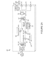
- FIG. 2A is a block diagram depicting an exemplary amplifier system according to various aspects of the present invention.
- FIG. 2B is a block diagram depicting another exemplary amplifier system according to various aspects of the present invention.
- FIG. 3 is a block diagram depicting an exemplary detection circuit in accordance with various aspects of the present invention.
- system 200 includes at least one first interface 205 for connecting to an HFC plant, headend, or other source that generates signals for distribution to one or more subscribers. Subscribers, in turn, interface with the amplifier through one or more second interfaces 210 . Signals received at the first interface 205 (e.g., from the HFC plant or headend) are transmitted along the forward signal path 202 and are provided to a subscriber via the second interface 210 .
- Signals received at the second interface are transmitted along the return signal path 204 and provided (e.g., to the HFC plant or headend) via the first interface 205 .
- a return path RF signal enters the system 200 through the second interfaced 210 , it is routed by the second diplex filter 234 along the return signal path 204 and a portion of the return RF signal is routed to the detection circuit 220 , the operation of which is described in more detail below.
- Alternate embodiments of systems of the present invention may include any desired number of first interfaces 205 and second interfaces 210 .
- the present invention may be utilized implemented as a house amplifier (also referred to as a drop amplifier, RF amplifier, and/or CATV amplifier) installed on the side of a subscriber's house or other building, as well as in a garage or basement.
- a house amplifier also referred to as a drop amplifier, RF amplifier, and/or CATV amplifier
- the exemplary system 200 depicted in FIG. 2A further includes a first diplex filter 225 (also known as a “diplexer”) coupled to the first interface 205 .
- the first diplex filter 225 includes a forward signal port 227 for directing signals received at the first interface 205 along the forward signal path 202 , and a return signal port 229 for directing signals from the return signal path 204 to the first interface 205 .
- a second diplex filter 230 includes a forward signal port for directing signals from the forward signal path 202 to the one or more second interfaces 210 (e.g., via RF splitter 250 ), and a return signal port 232 for directing signals received at the one or more second interfaces along the return signal path 204 .
- Any suitable diplex filter may be used in conjunction with the present invention.
- the system 200 includes a forward signal amplifier 240 coupled between the first diplex filter 225 and second diplex filter 230 , while a return signal amplifier 245 is coupled between the first diplex filter and switch 215 .
- the forward signal amplifier 240 and return signal amplifier 245 are used to help ensure that the forward signal and return signal, respectively, have an appropriate amplitude level. Any number and type of amplifiers, filters, regulators, and/or other devices may be used along the forward signal path 202 and/or return signal path 204 to adjust signals along the respective paths as desired.
- the present invention may include active and/or passive forward path amplification, as well as active and/or passive return path amplification.
- the system 200 includes an RF splitter 250 coupled between the second diplex filter 230 and the one or more second interfaces 210 .
- the RF splitter 250 includes four ports, each port coupled to a respective one of the second interfaces 210 .
- Systems of the present invention may include any number and type of splitters, and such splitters may include any desired number of ports.
- system 260 is in all respects the same as system 200 with the exception of an additional (bottom-most) second interface 210 coupled to a second RF splitter 265 , which is in turn coupled between the first interface 205 and the first diplex filter 225 .
- the second splitter 265 includes a first port coupled to the first diplex filter 225 , with a second port coupled to the bottom-most second interface 210 .
- the second splitter 265 allows for the bypass of the detection circuit 220 for a subscriber device (i.e., connected to the bottom interface 210 in this example) that is in frequent or constant communication with an HFC plant or headend via the first interface 205 , such as a cable modem.
- the second splitter 265 may include any number of desired ports connected to a second interface 210 to bypass the detection circuit 220 and switch 215 .
- a direct connection between a second interface 210 and splitter 265 may include any number and type of amplifiers, filters, regulators, and/or other devices.
- the system 200 includes a detection circuit 220 in communication with a switch 215 along the return signal path 204 .
- switch 215 allows passage of signals therethrough (i.e., the switch is “on”) while the switch prevents the passage of signals in a second state (i.e., the switch is “off”).
- the switch 215 is an RF gate. Any other suitable type of switch may be used in conjunction with the present invention, including an RF switch, voltage-controlled variable attenuator, and/or other device.
- an RF switch may be used for complete on/off control, while a voltage controlled attenuator can be employed to allow for full on, partial off control.
- the detection circuit 220 operates the switch 215 to the second (i.e., “off”) state such that ingress noise from one or more subscribers connected to the second interface(s) 210 does not enter the HFC coaxial plant or headend via the first interface 205 .
- the detection circuit 220 is used to operate the switch 215 between allowing (in the first state) and preventing (in the second state) passage of signals along the return signal path 204 . If the amplitude of the RF return signal is at or above a predetermined threshold, the detection circuit 220 will turn on the switch 215 (after a predetermined delay) allowing RF return signal to pass through.
- an exemplary detection circuit 220 is illustrated in FIG. 3 .
- an RF detector 310 detects whether signals received at the second interface (i.e., RF return path signals from a subscriber's cable modem, eMTA, settop box and/or other device) includes an amplitude of at least a predetermined level.
- the RF detector 310 demodulates the RF return path signal and provides the demodulated signal indicative of a voltage output level corresponding to the RF signal power of the return path signal.
- the amplifier 320 further amplifies the voltage output level from the RF detector 310 so that “on” or “off” conditions can be detected using standard logic components.
- the timing circuit 330 is configured to delay, by a predetermined amount of time, operation of the switch 215 to the second state.
- the timing circuit 330 may be configured to delay operation of the switch 215 by any suitable amount of time for any suitable purpose.
- the delay may be selected to avoid a loss of data due to the premature operation of the switch 215 to the second state.
- the timing circuit 330 enables the switch 215 to be operated to the first (“on”) state quickly, while operation of the switch to the second (“off”) state is delayed to ensure all signals pass through before the switch 215 is shut off.
- the detection circuit 220 of the present invention provides for the automatic operation of the switch 215 .
- a switch e.g., an RF gate
- a device employing such a remote-controlled switch is described in U.S. Patent App. No. 2008/0320541 to Zinevich.
- this approach can only be used for troubleshooting, where an attempt is made to identify sources of ingress noise.
- This approach has a number of limitation, including: (a) only an identification of the source of noise can be made, without providing an improvement in the level of ingress noise during normal operation; (b) accurate detection or identification of the source of noise may not even be possible due to the transient nature of certain ingress noise sources; (c) direct manipulation of the switch is required of a human operator; (d) network availability is interrupted during the troubleshooting; and (e) a reduction of the noise may not even be possible, especially when the ingress noise originates from within a customer's home.
Abstract
Description
Claims (12)
Priority Applications (2)
| Application Number | Priority Date | Filing Date | Title |
|---|---|---|---|
| US12/778,941 US8769597B2 (en) | 2008-06-23 | 2010-05-12 | Amplifier with noise reduction |
| PCT/US2011/033086 WO2011142940A1 (en) | 2010-05-12 | 2011-04-19 | Amplifier with noise reduction |
Applications Claiming Priority (3)
| Application Number | Priority Date | Filing Date | Title |
|---|---|---|---|
| US7489808P | 2008-06-23 | 2008-06-23 | |
| US12/487,367 US20090320085A1 (en) | 2008-06-23 | 2009-06-18 | House amplifier with return path gating |
| US12/778,941 US8769597B2 (en) | 2008-06-23 | 2010-05-12 | Amplifier with noise reduction |
Related Parent Applications (1)
| Application Number | Title | Priority Date | Filing Date |
|---|---|---|---|
| US12/487,367 Continuation-In-Part US20090320085A1 (en) | 2008-06-23 | 2009-06-18 | House amplifier with return path gating |
Publications (2)
| Publication Number | Publication Date |
|---|---|
| US20100223651A1 US20100223651A1 (en) | 2010-09-02 |
| US8769597B2 true US8769597B2 (en) | 2014-07-01 |
Family
ID=44914643
Family Applications (1)
| Application Number | Title | Priority Date | Filing Date |
|---|---|---|---|
| US12/778,941 Active 2031-02-07 US8769597B2 (en) | 2008-06-23 | 2010-05-12 | Amplifier with noise reduction |
Country Status (2)
| Country | Link |
|---|---|
| US (1) | US8769597B2 (en) |
| WO (1) | WO2011142940A1 (en) |
Cited By (2)
| Publication number | Priority date | Publication date | Assignee | Title |
|---|---|---|---|---|
| US9647851B2 (en) | 2008-10-13 | 2017-05-09 | Ppc Broadband, Inc. | Ingress noise inhibiting network interface device and method for cable television networks |
| US9813458B2 (en) | 2012-10-17 | 2017-11-07 | Ppc Broadband, Inc. | Network interface device and method having passive operation mode and noise management |
Families Citing this family (13)
| Publication number | Priority date | Publication date | Assignee | Title |
|---|---|---|---|---|
| US8769597B2 (en) | 2008-06-23 | 2014-07-01 | Pct International, Inc. | Amplifier with noise reduction |
| US20090320085A1 (en) | 2008-06-23 | 2009-12-24 | Jon-En Wang | House amplifier with return path gating |
| GB201202147D0 (en) * | 2012-02-08 | 2012-03-21 | Technetix Bv | Interface apparatus |
| US9722711B2 (en) * | 2012-02-14 | 2017-08-01 | Cable Television Laboratories, Inc. | Noise management for communication system |
| US10348005B2 (en) | 2012-06-11 | 2019-07-09 | Pct International, Inc. | Coaxial cable connector with improved compression band |
| US9577954B2 (en) * | 2012-06-29 | 2017-02-21 | Cable Television Laboratories, Inc. | Time domain duplex (TDD) switching system |
| US9043855B2 (en) * | 2012-07-23 | 2015-05-26 | Maxlinear, Inc. | Noise suppression in a hybrid fiber coaxial network |
| US9654062B2 (en) | 2013-06-25 | 2017-05-16 | Pct International, Inc. | Return path noise reducing amplifier with bypass signal |
| KR101336133B1 (en) * | 2013-07-09 | 2013-12-03 | 반도전자통신주식회사 | An apparatus for controlling reverse noise in hfc network and the method thereof |
| WO2018057671A1 (en) | 2016-09-21 | 2018-03-29 | Pct International, Inc. | Connector with a locking mechanism, moveable collet, and floating contact means |
| US10770808B2 (en) | 2016-09-21 | 2020-09-08 | Pct International, Inc. | Connector with a locking mechanism |
| US10348043B2 (en) | 2016-12-28 | 2019-07-09 | Pct International, Inc. | Progressive lock washer assembly for coaxial cable connectors |
| US10079447B1 (en) | 2017-07-21 | 2018-09-18 | Pct International, Inc. | Coaxial cable connector with an expandable pawl |
Citations (49)
| Publication number | Priority date | Publication date | Assignee | Title |
|---|---|---|---|---|
| US5016244A (en) | 1989-09-08 | 1991-05-14 | Honeywell Inc. | Method for controlling failover between redundant network interface modules |
| WO1996008925A1 (en) | 1994-09-12 | 1996-03-21 | Scientific-Atlanta, Inc. | Cable television apparatus employing two-way communication |
| US5696895A (en) | 1995-05-19 | 1997-12-09 | Compaq Computer Corporation | Fault tolerant multiple network servers |
| US5724344A (en) | 1996-04-02 | 1998-03-03 | Beck; William Federick | Amplifier using a single forward pilot signal to control forward and return automatic slope circuits therein |
| US5815794A (en) * | 1995-09-01 | 1998-09-29 | Cable Television Laboratories, Inc. | Undesirable energy suppression system in the return path of a bidirectional cable network having dynamically allocated time slots |
| US6075784A (en) | 1998-06-08 | 2000-06-13 | Jetstream Communications, Inc. | System and method for communicating voice and data over a local packet network |
| US6094211A (en) | 1996-08-15 | 2000-07-25 | Com21, Inc. | TV and data cable system ingress noise blocker |
| USH1858H (en) | 1998-06-26 | 2000-09-05 | Scientific-Atlanta, Inc. | Radio frequency sensed, switched reverse path tap |
| US6175565B1 (en) | 1997-09-17 | 2001-01-16 | Nokia Corporation | Serial telephone adapter |
| US6202169B1 (en) | 1997-12-31 | 2001-03-13 | Nortel Networks Corporation | Transitioning between redundant computer systems on a network |
| US20020010817A1 (en) | 1999-01-29 | 2002-01-24 | Han-Chung Yeh | Host signal processing modem with a signal processing accelerator |
| US6348837B1 (en) | 2000-08-08 | 2002-02-19 | Scientific-Atlanta, Inc. | Bi-directional amplifier having a single gain block for amplifying both forward and reverse signals |
| US6373817B1 (en) | 1999-12-30 | 2002-04-16 | At&T Corp. | Chase me system |
| US20020083476A1 (en) | 2000-03-21 | 2002-06-27 | Mcnamara Robert | Method and apparatus for reducing the flow of RF noise from subscriber's premise cable systems into the reverse transmission path of two-way cable networks |
| US20020101818A1 (en) | 2001-01-31 | 2002-08-01 | Joe Teixeira | System and method for providing analog telephone service when voice over IP over SDSL service is interrupted due to power failure |
| US6477197B1 (en) | 1998-06-30 | 2002-11-05 | Arris International, Inc. | Method and apparatus for a cable modem upstream RF switching system |
| US20030014765A1 (en) | 2000-02-16 | 2003-01-16 | Ljungdahl Kjell Arne | Cable tv system or other similar communication system |
| US20030066082A1 (en) | 2000-08-30 | 2003-04-03 | Avi Kliger | Home network system and method |
| US20030121056A1 (en) * | 2001-12-21 | 2003-06-26 | Sorenson Donald C. | HFC reverse path using an intelligent dynamic switch |
| US6640239B1 (en) | 1999-11-10 | 2003-10-28 | Garuda Network Corporation | Apparatus and method for intelligent scalable switching network |
| US20030214939A1 (en) | 2002-05-15 | 2003-11-20 | Ismail I. Eldumiati | Method and apparatus for providing life line service to access gateway telephony subscribers |
| US6671253B1 (en) | 1999-09-21 | 2003-12-30 | International Business Machines Corporation | Method and system for providing peer redundancy to asynchronous transfer mode emulated local-area networks |
| US6681100B1 (en) | 1999-03-15 | 2004-01-20 | Teletronics International, Inc. | Smart amplifier for time division duplex wireless applications |
| US6690789B1 (en) | 2000-08-31 | 2004-02-10 | Cisco Technology, Inc. | Fault tolerant telephony control |
| US20040027992A1 (en) | 2002-07-29 | 2004-02-12 | Ingo Volkening | DSL communication apparatus with lifeline functionality |
| JP2004080483A (en) | 2002-08-20 | 2004-03-11 | Ntt Communications Kk | Adapter for voice over an internet protocol |
| US6735302B1 (en) | 1999-05-28 | 2004-05-11 | Broadcom Corporation | DSP based SLIC architecture with current-sensing voltage synthesis impedance matching and DC feed control |
| US6757910B1 (en) * | 2000-06-08 | 2004-06-29 | C-Cor.Net Corporation | Adaptive filter for reducing ingress noise in CATV return signals |
| US6785907B1 (en) | 1998-08-14 | 2004-08-31 | Cableserv Electronics, Ltd | Amplifier and equalizer for two way cable transmission |
| US20040170160A1 (en) | 2003-02-28 | 2004-09-02 | Innomedia Pte Ltd. | Internet telephone system with hunting diversion |
| US6788169B1 (en) | 1999-12-29 | 2004-09-07 | Broadband Royalty Corporation | Amplifier composite triple beat (CTB) reduction by phase filtering |
| US6839829B1 (en) | 2000-01-18 | 2005-01-04 | Cisco Technology, Inc. | Routing protocol based redundancy design for shared-access networks |
| JP2005005875A (en) | 2003-06-10 | 2005-01-06 | Nec Tohoku Ltd | VoIP SWITCHING DEVICE |
| US20050026571A1 (en) | 2003-08-01 | 2005-02-03 | Northrop Grumman Space & Mission Systems Corporation | Asymmetric, optimized common-source bi-directional amplifier |
| US20050169056A1 (en) | 2002-12-10 | 2005-08-04 | Berkman William H. | Power line communications device and method |
| US6993286B2 (en) | 2002-08-02 | 2006-01-31 | Radio Frequency Systems, Inc. | Dual band bidirectional amplifier for wireless communication |
| US20060035602A1 (en) | 1999-02-18 | 2006-02-16 | Young Michael F | Method of sensing descrete operational states |
| US20060063508A1 (en) | 2004-04-30 | 2006-03-23 | Shiping He | Miniature bidirectional amplifier |
| US7093054B1 (en) | 2000-01-14 | 2006-08-15 | National Semiconductor Corporation | Method of transferring signals between a TTL microcontroller and a RS232 device |
| US20060205442A1 (en) | 2005-03-10 | 2006-09-14 | Neil Phillips | Bi-directional amplifier with non-interruptible port |
| US20060248567A1 (en) | 2005-04-28 | 2006-11-02 | Signal Dynamics | Signal transmission system and method |
| US7254827B1 (en) | 2000-05-08 | 2007-08-07 | Sunrise Telecom Incorporated | Ingress monitoring system and method |
| US20090098831A1 (en) | 2007-10-10 | 2009-04-16 | Qualcomm Incorporated | Dual band radio frequency transmitter |
| US7530091B2 (en) | 2004-07-19 | 2009-05-05 | Pct International, Inc. | VOIP drop amplifier |
| US20090320085A1 (en) | 2008-06-23 | 2009-12-24 | Jon-En Wang | House amplifier with return path gating |
| US7675843B2 (en) | 1995-02-06 | 2010-03-09 | Adc Telecommunications, Inc. | Multipoint-to-point communication using orthogonal frequency division multiplexing |
| US20100095344A1 (en) | 2008-10-13 | 2010-04-15 | Newby Charles F | Ingress Noise Inhibiting Network Interface Device and Method for Cable Television Networks |
| US7707615B2 (en) * | 2004-06-10 | 2010-04-27 | Time Warner Cable, Inc. | Establishing a return path in a forward path cable television testing environment |
| US20100223651A1 (en) | 2008-06-23 | 2010-09-02 | Jon-En Wang | Amplifier with noise reduction |
-
2010
- 2010-05-12 US US12/778,941 patent/US8769597B2/en active Active
-
2011
- 2011-04-19 WO PCT/US2011/033086 patent/WO2011142940A1/en active Application Filing
Patent Citations (52)
| Publication number | Priority date | Publication date | Assignee | Title |
|---|---|---|---|---|
| US5016244A (en) | 1989-09-08 | 1991-05-14 | Honeywell Inc. | Method for controlling failover between redundant network interface modules |
| WO1996008925A1 (en) | 1994-09-12 | 1996-03-21 | Scientific-Atlanta, Inc. | Cable television apparatus employing two-way communication |
| US5826167A (en) | 1994-09-12 | 1998-10-20 | Scientific-Atlanta, Inc. | Bi-directional cable television system including a UHF filter |
| US7675843B2 (en) | 1995-02-06 | 2010-03-09 | Adc Telecommunications, Inc. | Multipoint-to-point communication using orthogonal frequency division multiplexing |
| US5696895A (en) | 1995-05-19 | 1997-12-09 | Compaq Computer Corporation | Fault tolerant multiple network servers |
| US5815794A (en) * | 1995-09-01 | 1998-09-29 | Cable Television Laboratories, Inc. | Undesirable energy suppression system in the return path of a bidirectional cable network having dynamically allocated time slots |
| US5724344A (en) | 1996-04-02 | 1998-03-03 | Beck; William Federick | Amplifier using a single forward pilot signal to control forward and return automatic slope circuits therein |
| US6094211A (en) | 1996-08-15 | 2000-07-25 | Com21, Inc. | TV and data cable system ingress noise blocker |
| US6175565B1 (en) | 1997-09-17 | 2001-01-16 | Nokia Corporation | Serial telephone adapter |
| US6202169B1 (en) | 1997-12-31 | 2001-03-13 | Nortel Networks Corporation | Transitioning between redundant computer systems on a network |
| US6075784A (en) | 1998-06-08 | 2000-06-13 | Jetstream Communications, Inc. | System and method for communicating voice and data over a local packet network |
| USH1858H (en) | 1998-06-26 | 2000-09-05 | Scientific-Atlanta, Inc. | Radio frequency sensed, switched reverse path tap |
| US6477197B1 (en) | 1998-06-30 | 2002-11-05 | Arris International, Inc. | Method and apparatus for a cable modem upstream RF switching system |
| US6785907B1 (en) | 1998-08-14 | 2004-08-31 | Cableserv Electronics, Ltd | Amplifier and equalizer for two way cable transmission |
| US20020010817A1 (en) | 1999-01-29 | 2002-01-24 | Han-Chung Yeh | Host signal processing modem with a signal processing accelerator |
| US20060035602A1 (en) | 1999-02-18 | 2006-02-16 | Young Michael F | Method of sensing descrete operational states |
| US6681100B1 (en) | 1999-03-15 | 2004-01-20 | Teletronics International, Inc. | Smart amplifier for time division duplex wireless applications |
| US6735302B1 (en) | 1999-05-28 | 2004-05-11 | Broadcom Corporation | DSP based SLIC architecture with current-sensing voltage synthesis impedance matching and DC feed control |
| US6671253B1 (en) | 1999-09-21 | 2003-12-30 | International Business Machines Corporation | Method and system for providing peer redundancy to asynchronous transfer mode emulated local-area networks |
| US6640239B1 (en) | 1999-11-10 | 2003-10-28 | Garuda Network Corporation | Apparatus and method for intelligent scalable switching network |
| US6788169B1 (en) | 1999-12-29 | 2004-09-07 | Broadband Royalty Corporation | Amplifier composite triple beat (CTB) reduction by phase filtering |
| US6373817B1 (en) | 1999-12-30 | 2002-04-16 | At&T Corp. | Chase me system |
| US7093054B1 (en) | 2000-01-14 | 2006-08-15 | National Semiconductor Corporation | Method of transferring signals between a TTL microcontroller and a RS232 device |
| US6839829B1 (en) | 2000-01-18 | 2005-01-04 | Cisco Technology, Inc. | Routing protocol based redundancy design for shared-access networks |
| US20030014765A1 (en) | 2000-02-16 | 2003-01-16 | Ljungdahl Kjell Arne | Cable tv system or other similar communication system |
| US20020083476A1 (en) | 2000-03-21 | 2002-06-27 | Mcnamara Robert | Method and apparatus for reducing the flow of RF noise from subscriber's premise cable systems into the reverse transmission path of two-way cable networks |
| US7254827B1 (en) | 2000-05-08 | 2007-08-07 | Sunrise Telecom Incorporated | Ingress monitoring system and method |
| US6757910B1 (en) * | 2000-06-08 | 2004-06-29 | C-Cor.Net Corporation | Adaptive filter for reducing ingress noise in CATV return signals |
| US6348837B1 (en) | 2000-08-08 | 2002-02-19 | Scientific-Atlanta, Inc. | Bi-directional amplifier having a single gain block for amplifying both forward and reverse signals |
| US20030066082A1 (en) | 2000-08-30 | 2003-04-03 | Avi Kliger | Home network system and method |
| US6690789B1 (en) | 2000-08-31 | 2004-02-10 | Cisco Technology, Inc. | Fault tolerant telephony control |
| US20020101818A1 (en) | 2001-01-31 | 2002-08-01 | Joe Teixeira | System and method for providing analog telephone service when voice over IP over SDSL service is interrupted due to power failure |
| WO2003056728A1 (en) | 2001-12-21 | 2003-07-10 | Scientific-Atlanta, Inc. | Hfc reverse path using an intelligent dynamic switch |
| US20030121056A1 (en) * | 2001-12-21 | 2003-06-26 | Sorenson Donald C. | HFC reverse path using an intelligent dynamic switch |
| US20030214939A1 (en) | 2002-05-15 | 2003-11-20 | Ismail I. Eldumiati | Method and apparatus for providing life line service to access gateway telephony subscribers |
| US20040027992A1 (en) | 2002-07-29 | 2004-02-12 | Ingo Volkening | DSL communication apparatus with lifeline functionality |
| US6993286B2 (en) | 2002-08-02 | 2006-01-31 | Radio Frequency Systems, Inc. | Dual band bidirectional amplifier for wireless communication |
| JP2004080483A (en) | 2002-08-20 | 2004-03-11 | Ntt Communications Kk | Adapter for voice over an internet protocol |
| US20050169056A1 (en) | 2002-12-10 | 2005-08-04 | Berkman William H. | Power line communications device and method |
| US20040170160A1 (en) | 2003-02-28 | 2004-09-02 | Innomedia Pte Ltd. | Internet telephone system with hunting diversion |
| JP2005005875A (en) | 2003-06-10 | 2005-01-06 | Nec Tohoku Ltd | VoIP SWITCHING DEVICE |
| US20050026571A1 (en) | 2003-08-01 | 2005-02-03 | Northrop Grumman Space & Mission Systems Corporation | Asymmetric, optimized common-source bi-directional amplifier |
| US20060063508A1 (en) | 2004-04-30 | 2006-03-23 | Shiping He | Miniature bidirectional amplifier |
| US7707615B2 (en) * | 2004-06-10 | 2010-04-27 | Time Warner Cable, Inc. | Establishing a return path in a forward path cable television testing environment |
| US7530091B2 (en) | 2004-07-19 | 2009-05-05 | Pct International, Inc. | VOIP drop amplifier |
| US20060205442A1 (en) | 2005-03-10 | 2006-09-14 | Neil Phillips | Bi-directional amplifier with non-interruptible port |
| US20060248567A1 (en) | 2005-04-28 | 2006-11-02 | Signal Dynamics | Signal transmission system and method |
| US20090098831A1 (en) | 2007-10-10 | 2009-04-16 | Qualcomm Incorporated | Dual band radio frequency transmitter |
| US20090320085A1 (en) | 2008-06-23 | 2009-12-24 | Jon-En Wang | House amplifier with return path gating |
| US20100223651A1 (en) | 2008-06-23 | 2010-09-02 | Jon-En Wang | Amplifier with noise reduction |
| US20100095344A1 (en) | 2008-10-13 | 2010-04-15 | Newby Charles F | Ingress Noise Inhibiting Network Interface Device and Method for Cable Television Networks |
| WO2011142940A1 (en) | 2010-05-12 | 2011-11-17 | Pct International, Inc. | Amplifier with noise reduction |
Non-Patent Citations (7)
| Title |
|---|
| "Clipcomm CP-IOOP," VOIPSupply.com http://www.voipsupply.conn/product-info.php?products-id=305, 2 pages printed from Internet Jun. 6, 2005. |
| "Clipcomm CP-IOOP," VOIPSupply.com http://www.voipsupply.conn/product—info.php?products—id=305, 2 pages printed from Internet Jun. 6, 2005. |
| Bi-directional amplifiers by the Twister Group, 3 pages printed Jul. 9, 2008, http://www.thewistergroup.com/category/new-arrivals-pico-macom.html. |
| Dual direction transmission diplex drop amplifier by Alibaba.com, 2 pages pritned Jul. 9, 2008, http://www.alibaba.com/catalog/20591299/Diplex-Drop-Amplifier.html. |
| Dual direction transmission diplex drop amplifier by Alibaba.com, 2 pages pritned Jul. 9, 2008, http://www.alibaba.com/catalog/20591299/Diplex—Drop—Amplifier.html. |
| International Search Report and Written Opinion; International Patent Application No. PCT/US2011/033086; Filed: Apr. 19, 2011; Applicant: PCT International, Inc.; Mailed on Jul. 27, 2011. |
| Non-Final Office Action U.S. Appl. No. 12/487,367 Mailed on Sep. 2, 2011, Applicant Jon-En Wang, 10 pages. |
Cited By (5)
| Publication number | Priority date | Publication date | Assignee | Title |
|---|---|---|---|---|
| US9647851B2 (en) | 2008-10-13 | 2017-05-09 | Ppc Broadband, Inc. | Ingress noise inhibiting network interface device and method for cable television networks |
| US10045056B2 (en) | 2008-10-13 | 2018-08-07 | Ppc Broadband, Inc. | Ingress noise inhibiting network interface device and method for cable television networks |
| US10187673B2 (en) | 2008-10-13 | 2019-01-22 | Ppc Broadband, Inc. | Ingress noise inhibiting network interface device and method for cable television networks |
| US9813458B2 (en) | 2012-10-17 | 2017-11-07 | Ppc Broadband, Inc. | Network interface device and method having passive operation mode and noise management |
| US9948687B2 (en) | 2012-10-17 | 2018-04-17 | Ppc Broadband, Inc. | Network interface device and method having passive operation mode and noise management |
Also Published As
| Publication number | Publication date |
|---|---|
| US20100223651A1 (en) | 2010-09-02 |
| WO2011142940A1 (en) | 2011-11-17 |
Similar Documents
| Publication | Publication Date | Title |
|---|---|---|
| US8769597B2 (en) | Amplifier with noise reduction | |
| US20140254441A1 (en) | Amplifier with noise reduction | |
| US11102529B2 (en) | Echo cancellation in a bidirectional communication system for out of band signaling to a user device | |
| US20210344870A1 (en) | Method and apparatus for reducing isolation in a home network | |
| US8705417B2 (en) | In-network home gateway for hybrid fiber-coax network | |
| US9247310B2 (en) | DOCSIS out-of-band control signal frequency conversion for legacy set-top boxes | |
| US11601710B2 (en) | Self interference cancellation for high performance transceivers | |
| US7617517B2 (en) | Cable modem including filtering based on frequency band | |
| US9729936B2 (en) | Interference reduction for upstream signals in communication networks | |
| US20090154537A1 (en) | Frequency Selection Cable Reflector | |
| US6888883B1 (en) | Method and apparatus for reducing noise leakage from a cable modem | |
| US9654062B2 (en) | Return path noise reducing amplifier with bypass signal | |
| US7841871B2 (en) | Methods and apparatus for transferring digital packet-based data | |
| US20230300423A1 (en) | Arrangement for adjusting frequency response | |
| FI129936B (en) | An arrangement for aligning upstream path | |
| EP3707831B1 (en) | An arrangement for catv network segmentation | |
| US9391819B1 (en) | Systems and methods for preventing energy leakage in communications systems | |
| JP4663399B2 (en) | CATV system | |
| TW202301835A (en) | System and method for identifying network equipment from a remote location | |
| Volpe | DOCSIS Pre-Equalization: Vastly Powerful, Often Undervalued | |
| WO2020157370A1 (en) | A method for adjusting parameters of a network element | |
| WO2020128135A1 (en) | A method for adjusting parameters of a network element |
Legal Events
| Date | Code | Title | Description |
|---|---|---|---|
| AS | Assignment |
Owner name: PCT INTERNATIONAL, INC., ARIZONA Free format text: ASSIGNMENT OF ASSIGNORS INTEREST;ASSIGNOR:WANG, JON-EN;REEL/FRAME:026067/0463 Effective date: 20100423 |
|
| STCF | Information on status: patent grant |
Free format text: PATENTED CASE |
|
| AS | Assignment |
Owner name: BIBBY FINANCIAL SERVICES (CA) INC, CALIFORNIA Free format text: SECURITY INTEREST;ASSIGNOR:PCT INTERNATIONAL, INC.;REEL/FRAME:033832/0595 Effective date: 20140806 |
|
| MAFP | Maintenance fee payment |
Free format text: PAYMENT OF MAINTENANCE FEE, 4TH YR, SMALL ENTITY (ORIGINAL EVENT CODE: M2551) Year of fee payment: 4 |
|
| MAFP | Maintenance fee payment |
Free format text: PAYMENT OF MAINTENANCE FEE, 8TH YR, SMALL ENTITY (ORIGINAL EVENT CODE: M2552); ENTITY STATUS OF PATENT OWNER: SMALL ENTITY Year of fee payment: 8 |
|
| AS | Assignment |
Owner name: SALLYPORT COMMERCIAL FINANCE, LLC, TEXAS Free format text: SECURITY INTEREST;ASSIGNOR:PCT INTERNATIONAL, INC;REEL/FRAME:059126/0491 Effective date: 20181204 |