US8773390B1 - Biometric identification devices, methods and systems having touch surfaces - Google Patents
Biometric identification devices, methods and systems having touch surfaces Download PDFInfo
- Publication number
- US8773390B1 US8773390B1 US12/767,424 US76742410A US8773390B1 US 8773390 B1 US8773390 B1 US 8773390B1 US 76742410 A US76742410 A US 76742410A US 8773390 B1 US8773390 B1 US 8773390B1
- Authority
- US
- United States
- Prior art keywords
- sense
- values
- human hand
- capacitance
- touch
- Prior art date
- Legal status (The legal status is an assumption and is not a legal conclusion. Google has not performed a legal analysis and makes no representation as to the accuracy of the status listed.)
- Expired - Fee Related, expires
Links
- 238000000034 method Methods 0.000 title claims description 42
- 238000012545 processing Methods 0.000 claims abstract description 31
- 238000005259 measurement Methods 0.000 claims description 44
- 230000004044 response Effects 0.000 claims description 8
- 238000006243 chemical reaction Methods 0.000 claims description 5
- 238000010586 diagram Methods 0.000 description 16
- 230000006870 function Effects 0.000 description 12
- 230000009471 action Effects 0.000 description 9
- 238000001514 detection method Methods 0.000 description 7
- 230000033001 locomotion Effects 0.000 description 6
- 238000013519 translation Methods 0.000 description 6
- 238000004458 analytical method Methods 0.000 description 5
- 238000013459 approach Methods 0.000 description 4
- 238000009795 derivation Methods 0.000 description 4
- 238000012905 input function Methods 0.000 description 4
- 239000004020 conductor Substances 0.000 description 2
- 238000013500 data storage Methods 0.000 description 2
- 230000003247 decreasing effect Effects 0.000 description 2
- 241000218691 Cupressaceae Species 0.000 description 1
- 230000004075 alteration Effects 0.000 description 1
- 230000008901 benefit Effects 0.000 description 1
- 210000000746 body region Anatomy 0.000 description 1
- 230000037237 body shape Effects 0.000 description 1
- 238000004364 calculation method Methods 0.000 description 1
- 230000001413 cellular effect Effects 0.000 description 1
- 230000008030 elimination Effects 0.000 description 1
- 238000003379 elimination reaction Methods 0.000 description 1
- 238000000605 extraction Methods 0.000 description 1
- AMGQUBHHOARCQH-UHFFFAOYSA-N indium;oxotin Chemical compound [In].[Sn]=O AMGQUBHHOARCQH-UHFFFAOYSA-N 0.000 description 1
- 230000010354 integration Effects 0.000 description 1
- 230000003993 interaction Effects 0.000 description 1
- 239000004973 liquid crystal related substance Substances 0.000 description 1
- 229910052751 metal Inorganic materials 0.000 description 1
- 239000002184 metal Substances 0.000 description 1
- 229910001092 metal group alloy Inorganic materials 0.000 description 1
- 150000002739 metals Chemical class 0.000 description 1
- 230000002093 peripheral effect Effects 0.000 description 1
- 230000008569 process Effects 0.000 description 1
- 238000005070 sampling Methods 0.000 description 1
- 239000004065 semiconductor Substances 0.000 description 1
- 238000006467 substitution reaction Methods 0.000 description 1
- 230000000007 visual effect Effects 0.000 description 1
Images


Classifications
-
- G—PHYSICS
- G06—COMPUTING; CALCULATING OR COUNTING
- G06F—ELECTRIC DIGITAL DATA PROCESSING
- G06F3/00—Input arrangements for transferring data to be processed into a form capable of being handled by the computer; Output arrangements for transferring data from processing unit to output unit, e.g. interface arrangements
- G06F3/01—Input arrangements or combined input and output arrangements for interaction between user and computer
- G06F3/03—Arrangements for converting the position or the displacement of a member into a coded form
- G06F3/041—Digitisers, e.g. for touch screens or touch pads, characterised by the transducing means
- G06F3/045—Digitisers, e.g. for touch screens or touch pads, characterised by the transducing means using resistive elements, e.g. a single continuous surface or two parallel surfaces put in contact
-
- G—PHYSICS
- G06—COMPUTING; CALCULATING OR COUNTING
- G06F—ELECTRIC DIGITAL DATA PROCESSING
- G06F3/00—Input arrangements for transferring data to be processed into a form capable of being handled by the computer; Output arrangements for transferring data from processing unit to output unit, e.g. interface arrangements
- G06F3/01—Input arrangements or combined input and output arrangements for interaction between user and computer
- G06F3/03—Arrangements for converting the position or the displacement of a member into a coded form
- G06F3/041—Digitisers, e.g. for touch screens or touch pads, characterised by the transducing means
- G06F3/044—Digitisers, e.g. for touch screens or touch pads, characterised by the transducing means by capacitive means
- G06F3/0446—Digitisers, e.g. for touch screens or touch pads, characterised by the transducing means by capacitive means using a grid-like structure of electrodes in at least two directions, e.g. using row and column electrodes
-
- G—PHYSICS
- G06—COMPUTING; CALCULATING OR COUNTING
- G06F—ELECTRIC DIGITAL DATA PROCESSING
- G06F21/00—Security arrangements for protecting computers, components thereof, programs or data against unauthorised activity
- G06F21/30—Authentication, i.e. establishing the identity or authorisation of security principals
- G06F21/31—User authentication
- G06F21/32—User authentication using biometric data, e.g. fingerprints, iris scans or voiceprints
-
- G—PHYSICS
- G06—COMPUTING; CALCULATING OR COUNTING
- G06F—ELECTRIC DIGITAL DATA PROCESSING
- G06F3/00—Input arrangements for transferring data to be processed into a form capable of being handled by the computer; Output arrangements for transferring data from processing unit to output unit, e.g. interface arrangements
- G06F3/01—Input arrangements or combined input and output arrangements for interaction between user and computer
- G06F3/03—Arrangements for converting the position or the displacement of a member into a coded form
- G06F3/041—Digitisers, e.g. for touch screens or touch pads, characterised by the transducing means
- G06F3/0416—Control or interface arrangements specially adapted for digitisers
-
- G—PHYSICS
- G06—COMPUTING; CALCULATING OR COUNTING
- G06F—ELECTRIC DIGITAL DATA PROCESSING
- G06F3/00—Input arrangements for transferring data to be processed into a form capable of being handled by the computer; Output arrangements for transferring data from processing unit to output unit, e.g. interface arrangements
- G06F3/01—Input arrangements or combined input and output arrangements for interaction between user and computer
- G06F3/03—Arrangements for converting the position or the displacement of a member into a coded form
- G06F3/041—Digitisers, e.g. for touch screens or touch pads, characterised by the transducing means
- G06F3/044—Digitisers, e.g. for touch screens or touch pads, characterised by the transducing means by capacitive means
-
- G—PHYSICS
- G06—COMPUTING; CALCULATING OR COUNTING
- G06F—ELECTRIC DIGITAL DATA PROCESSING
- G06F2203/00—Indexing scheme relating to G06F3/00 - G06F3/048
- G06F2203/041—Indexing scheme relating to G06F3/041 - G06F3/045
- G06F2203/04104—Multi-touch detection in digitiser, i.e. details about the simultaneous detection of a plurality of touching locations, e.g. multiple fingers or pen and finger
Definitions
- the present disclosure relates generally to biometric identification systems, and more particularly to biometric identification systems having a touch surface.
- FIG. 1 is a block diagram of a device according to one embodiment.
- FIG. 2 is a block diagram of a sense surface that may be included in embodiments.
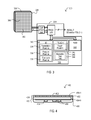
- FIG. 3 is a block diagram of a device according to another embodiment.
- FIG. 4 is a side cross sectional view of a touchscreen device according to a further embodiment.
- FIG. 5 is a schematic diagram showing one example of processing circuits that may be included in embodiments.
- FIGS. 6 to 8 show sense value acquisition operations according to various embodiments.
- FIGS. 9 to 11 show feature extraction operations according to various embodiments.
- FIG. 12 is a diagram showing angle and position compensation operations that may be included in the embodiments.
- FIG. 13 is a block schematic diagram of a system according to an embodiment.
- FIGS. 14 to 17 are diagrams of various particular embodiments.
- FIGS. 18A to 18E are a sequence of diagrams showing system operations according to one particular embodiment.
- FIG. 19 is a flow diagram of a method according to an embodiment.
- FIG. 20 is a flow diagram of a method according to a further embodiment.
- a touch surface used for a biometric identification operation may also be used as a user input device.
- a device 100 may include a sense surface 102 and processing circuits 104 .
- a sense surface 102 may include a number of sense locations (one shown as 106 ), each of which may detect the presence or absence of body part in contact with the touch surface 102 , as well as the extent to which the body part is present (e.g., size or proximity of the body part).
- a touch surface 102 has sufficient area to accommodate the body portion being measured. That is, a user does not “swipe” a hand or hand portion over the surface. Rather, the body part may be placed on the surface and maintained substantially motionless for the amount of time needed to acquire a measurement value at a set of sense locations (e.g., 106 ).
- a sense surface 102 may derive body shape data in various ways, including but not limited to capacitance sensing or resistance sensing, or any other suitable method for detecting contact of the body part with the surface.
- Processing circuits 104 may determine if a sensed body part matches stored biometric identification (ID) values to generate a match result (RESULT_ID).
- processing circuits 104 may include sense circuit 108 , processing section 110 , and biometric data store 112 .
- Sense circuits 108 may acquire sense values corresponding to sense locations (e.g., 106 ).
- sense circuits 108 may include analog-to-digital conversion circuits to convert analog sense values into digital values.
- sense circuits 108 may be capacitance sense circuits that sense a capacitance value at each sense location (e.g., 106 ).
- a processing section 110 may include a position translation section 114 , a feature derivation section 116 , and a feature comparison section 118 .
- a position translation section 114 may compensate for angular and/or positional offsets between an orientation of a sensed body portion and an orientation corresponding to the biometric data.
- a feature derivation section 116 may derive two dimensional measurements of a body portion sensed by sense locations (e.g., 106 ). As noted above, such measurements may correspond to a shape of a body portion. In some particular embodiments, a feature derivation section 116 may generate sensed biometric values corresponding to a shape of a body portion in contact with a sense surface, including but not limited to a width, length, diagonal, contact area, perimeter, and/or perimeter portion, including relative distances between such values.
- a sensed body portion may be a hand
- biometric values may measure any of: a finger, a finger portion, multiple fingers, a palm, a portion of a palm, and/or gaps between where portions of a hand contact a sense surface.
- a comparison section 118 may compare sensed biometric values to stored biometric ID values. Based upon such a comparison, a result value RESULT_ID may be generated indicating whether or not a match has been determined, and to which of the stored ID values a match has occurred.
- sections 114 , 116 , 118 may be realized by one or more processors executing predetermined instructions with arithmetic logic circuits. However, in alternate embodiments, custom circuits may execute all or a portion of such functions.
- a biometric data store 112 may store biometric ID data for access by section 118 to compare against sensed biometric values.
- a biometric data store 112 may include nonvolatile memory circuits for retaining such values in absence of power to a device.
- a device may generate sensed biometric values in response to two dimensional features of body portion placed on a sense surface, and compare such values to stored biometric data values.
- a sense surface that may be included in embodiments is shown in a top plan view and designated by the reference character 202 .
- a sense surface may utilize capacitance sensing to determine contact of a body portion with the surface, and may be one particular example of that shown as 102 in FIG. 1 .
- a sense surface 202 may include sense locations (one shown as 206 ) arranged in an orthogonal array. Each sense location (e.g., 206 ) may be formed by a discrete sense element (e.g., conductive element at sense location), or a combination of elements (y-direction element and x-direction elements at each location). Capacitance sense elements may be formed from any suitable conductive material, including metals and metal alloys. However, in particular touchscreen embodiments (e.g., those with combination touch detection/display functions), sense elements may be formed from a transparent conductive material, such as indium tin oxide (ITO), as but one example. In the embodiment shown, a capacitance value at a sense location (e.g., 206 ) may be acquired via array connections 222 - 0 and 222 - 1 .
- ITO indium tin oxide
- a sense surface 202 may provide direct connections to sense elements to enable direct access to sense locations (e.g., 206 ). However, a sense surface may optionally include decoding circuits ( 220 - 0 and - 1 ) for selectively accessing sense locations (e.g., 206 ).
- capacitance sensing may be used to acquire two dimensional biometric data based on features of body portion placed on a sense surface.
- a device according to another embodiment is shown in a block diagram and designated by the general reference character 300 .
- device 300 may be one implementation of that shown in FIG. 1 .
- a device 300 may include a touchscreen 324 and processing circuits 304 .
- a touchscreen 324 may include a sense surface 302 formed over a display 326 .
- a sense surface 302 may take the form of those described herein, or equivalents, but include transparent sensor elements to ensure that display 326 may be observed through the touch surface 302 .
- a display 326 may be any type of display for the device application, and may include, without limitation, a liquid crystal display (LCD), light emitting diode (LED) display (including organic LED (OLED) displays), or electrophoretic (or other so-called electronic ink type) displays.
- LCD liquid crystal display
- LED light emitting diode
- OLED organic LED
- electrophoretic or other so-called electronic ink type
- a touchscreen 324 may provide a biometric input, a user input, and a user output.
- a biometric input may convey sense values corresponding to a body portion shape according to techniques described herein, and equivalents.
- a user input may convey touch locations and/or touch types generated by a user touching touch surface 302 .
- sense values for both types of inputs e.g., biometric ID and touch detection
- a user output of touchscreen 324 may be provided by display 326 presenting visual images.
- touch inputs in combination with a display may create a user interface for the device.
- processing circuits 304 may perform multiple functions, including a biometric ID function and a user input function.
- a biometric ID function processing circuits 304 may determine if values generated from a sensed body part match stored biometric ID values.
- processing circuits 304 may derive locations of one or more touches, so that such touches may be interpreted as user inputs.
- a user input function may distinguish types of touches as well. For example, touch speeds and/or directions may be evaluated to detect particular types of touch events (e.g., taps, motions).
- processing circuits 304 may include sense circuit 308 , a processor section 328 , first memory 330 , and a second memory 332 .
- Sense circuits 308 may operate as described for item 108 in FIG. 1 , or in an equivalent manner.
- a processor section 328 may include one or more processors that execute predetermined instructions located within a first memory 330 .
- a processor section 310 may generate output signals RESULT, which may vary according to mode. More particularly, in an ID mode, output signals RESULT may indicate whether or not a sensed body portion is considered to match stored biometric ID data. In contrast, in a touch mode, output signals RESULT may identify location and/or type of touch on a sense surface 302 .
- a first memory 330 may be a substantially nonvolatile memory that stores instructions for execution by a processor section 310 , as well as data for use by processor section 310 .
- first memory 330 may be divided into ID instructions 340 , touch instructions 342 , and data storage 344 .
- ID instructions 340 may include a translation routine 334 , a feature routine 336 , and a compare routine 338 .
- a translation routine 334 , feature routine 336 and compare routine 338 may execute the same or equivalent operations described for position translation section 114 , feature derivation section 116 , and feature comparison section 118 , respectively, of FIG. 1 .
- translation and feature routines 334 / 336 may be portions of one analysis routine. In a very particular embodiment, such routines may be firmware for one or more integrated circuit devices.
- Sense instructions 342 may include a touch routine 346 that derives position data for touches and/or interprets types of touches. In one embodiment this may include determining the presence of multiple touch locations (e.g., multi-touch input).
- Data storage 344 may store biometric data 348 for use by processing section 328 when executing a compare routine 338 , to determine if a sensed body portion is determined to match biometric data 348 . It is understood that a “match” is not an exact match, and may include tolerance limits.
- a second memory 332 may store values sensed from touchscreen 324 for manipulation by processor section 328 .
- a second memory 332 may be substantially volatile, losing data in the absence of power.
- processing circuits 304 may be formed all, or in part by a programmable embedded system-on-chip from the PSoC® family of integrated circuit devices, manufactured by Cypress Semiconductor Corporation, of San Jose, Calif., U.S.A.
- routines stored in a nonvolatile memory may include loaded such routines into an operational memory from some other location of a larger system incorporating device 300 .
- a device may include a touchscreen which operates a biometric data input in one mode, and user control input in another mode.
- a device 400 is shown in a side cross sectional view, and designated by the general reference character 400 .
- a device 400 may be one very particular implementation of that shown in FIG. 3 .
- a device 400 may be conceptualized as including a touchscreen 424 and a circuit portion 450 .
- a touchscreen 424 may include a display 426 and a sensor array 452 .
- a sensor array 452 may be formed over display 426 and separated therefrom by a first transparent layer 454 - 0 .
- a second transparent layer 454 - 1 may be formed over sensor array 452 to form a sense surface 402 .
- a circuit portion 450 may be formed opposite to an image presenting side of display 426 .
- a circuit portion 450 may include processing circuits 404 that may perform biometric ID functions, as well as user input functions, as described herein and equivalents.
- a circuit portion 450 may include additional circuits 456 for controlling a display function of display 426 and run other applications for the device 400 .
- processing circuits that perform biometric ID functions may be integrated into a touchscreen device.
- Processing circuits 504 may be formed in a same IC, and may include an analog portion 504 - 0 and a digital portion 504 - 1 .
- An analog portion 504 - 0 may connect to a number of sense elements 560 - 0 to -n at input/outputs (I/Os) 562 - 0 to -n.
- I/Os ( 562 - 0 to -n) may be connected to a same sample node 558 by corresponding switches 564 - 0 to -n.
- Such an arrangement may enable sense elements ( 560 - 0 to -n) to be sequentially connected to sample node 558 for a capacitance measurement. Sequential sampling may provide for lower power consumption and fewer processing circuits than approaches that process signals in parallel.
- An analog portion 504 - 0 may also include a comparator 566 , a discharge switch 568 , a charge switch 570 , and a control and count circuit 572 . In combination, these circuit elements may generate a count value representative of a sense element value (e.g., capacitance) sensed at sample node 558 . Such a sensing operation may be according to integration techniques, successive approximation techniques, sigma-delta conversion, or any other suitable technique for measuring a signal at sample node 558 . Thus, an analog portion 504 - 0 may include analog-to-digital conversion circuits that generate a digital value (counts) from an analog value (raw value detected at sample node 558 ).
- a digital portion 504 - 1 may include a microcontroller 574 .
- a microcontroller 574 may execute predetermined operations on received count values to perform a biometric compare operation and/or determine the position of such objects.
- FIG. 6 shows a sense surface 602 divided into sense locations identifiable by X and Y locations (shown by X and Y axes).
- FIG. 6 also shows a body part position 676 (in this example a hand shown by a dashed line) above a sense surface 602 , as well as body part touch locations (solid lines, one shown as 678 ) showing where a body part portion contacts the sense surface 602 .
- a body part position 676 in this example a hand shown by a dashed line
- body part touch locations solid lines, one shown as 678
- FIG. 6 shows count values that may be acquired according to one very particular embodiment.
- sense location (3,1) (x, y coordinates) has a count value of “133”
- sense location (4,2) has a count value of “255”.
- a count value may correspond to the amount by which a sense location is physically contacted by a body part.
- FIG. 7 a sense operation like that of FIG. 6 is shown in a top plan view, but with a sense surface 702 of finer resolution that acquires sense values for two fingers.
- FIG. 7 shows a sense surface 702 divided into sense locations identifiable by X and Y locations, with body part position 776 above a sense surface 702 , as well as body part touch locations (one shown as 778 ). Corresponding count values are shown in sense locations (e.g., sense location (3,6) has a count value of “255”).
- FIG. 8 another sense operation like that of FIG. 8 is shown, but with a sense surface 802 acquiring sense values for a palm.
- FIG. 8 only shows body part touch locations (one shown as 878 ).
- Corresponding count values are shown in the same manner as FIGS. 6 and 7 (e.g., sense location (4,2) has a count value of “255”).
- embodiments may generate count values based on the amount by which body portion(s) contact sense locations on a sense surface. Such count value may be used to generate biometric data.
- measurement values are shown in a top plan view.
- FIG. 9 shows values that may be generated in response to sense values shown in FIG. 6 .
- Such measurement values may include any of: finger length measurements (one shown as 980 - 0 ), finger width measurements (one shown as 980 - 1 , and in this embodiment a width of multiple fingers), palm length measurements (one shown as 980 - 2 ), or palm width measurements (one shown as 980 - 3 ).
- Measurements may be made according to various methods. As but one example, a total body portion region may be detected by peripheral sense locations having values over a predetermined threshold. Minimum (and/or maximum) values, or differences in such values, may designate start and ending of a measurement region. A measurement value for a measurement region may then vary according to the values at sense locations within the measured region and/or adjacent to such a region.
- measurement values according to another particular embodiment are shown in a top plan view.
- FIG. 10 shows values that may be generated in response to sense values shown in FIG. 6 .
- Such measurement values may include shapes of a palm (one shown as 1082 ).
- a palm region may be derived from a total body region by detecting minimum corresponding to gaps between finger and palm regions. Contiguous sense locations above a threshold may be considered to belong to a same palm portion. Such areas may be increased or decreased based on values of bordering sense locations.
- measurement values are shown in a top plan view.
- FIG. 11 also shows values that may be generated in response to sense values shown in FIG. 6 .
- Such measurement values may include shapes of touch gaps (one shown as 1184 ) arising between areas where a body portion contacts a sense surface
- Measurements may be made according to various methods.
- gaps locations derived from minimum values within a contact region Contiguous sense values below a threshold may be considered to belong to a same gap.
- Gap areas may be increased or decreased based on values of bordering sense locations.
- a device may compensate for difference in orientation between the position of a sensed body portion, and the position of a body portion used to derive a biometric reference value.
- One particular compensation approach that may be included in the embodiments is shown in FIG. 12
- measurement values are shown in a top plan view for hand like that of FIG. 6 .
- the hand is rotated and offset with respect to an orientation like that of FIG. 6 .
- features of the scanned body part may be identified to derive the orientation of the body part.
- feature points may be identified (e.g., largest positive Y location 1286 - 0 , a minimum value surrounded by large values 1286 - 1 ) to derive an angular offset 1288 .
- one feature point location (e.g., 1286 - 1 ) may be compared to a reference point 1290 to determine a position offset.
- Such offset values may then be utilized to generate sense values and biometric features.
- measurement of biometric features may be derived with reference to feature points (e.g., 1286 - 0 / 1 ). That is, compensation and calculation are part of a same operation.
- Alternate embodiments may use any suitable compensation steps, according to various factors, including but not limited to: available processing powers, desired speed of result, amount of offset expected.
- a device that acquires biometric data and may also serve as a user touch input device may be included in various types of systems to provide both security and touch input information to a host device.
- Particular system embodiments will now be described. It is stressed that such embodiments are intended to be illustrative, and not exhaustive.
- a system 1392 may be a computing device including, but not limited to, desktop computing devices as well as portable computing devices, such as handheld electronic devices.
- a system 1392 may include a detection device 1300 and a computing section 1394 .
- a detection device 1300 may correspond to any of the devices described herein, or equivalents, and may operate in an ID mode to make a biometric reading of a body portion, and in a touch mode to provide user input values to the system.
- a computing section 1394 may be conceptualized as having a number of operational layers, including a security section 1395 , user interface 1396 and a main program layer 1398 .
- Security section 1395 may prevent access to some or all of the functions of system 1392 according to biometric match results from device 1300 .
- User interface software 1396 may accept touch position and/or type data from device. In some embodiments, user interface software 1396 may generate interrupts to notify when input events occur based on the detection and/or movement of a detected option. Alternatively, position information may be periodically polled.
- a main programming layer 1398 may include an operation system (OS) as one or more application programs (APP) for executing functions in response to inputs from detection device 1300 .
- a computing section 1394 may physically be implemented by one or more processors that execute predetermined instructions stored in a memory.
- a computing section 1394 may receive input values from other devices and/or interfaces in conjunction with those from detection device 1300 .
- a system 1492 may be a display device, and may be one implementation of that shown in FIG. 13 .
- a system host 1494 may include a display device for presenting an image, including viewing images and/or a graphical user interface.
- a system 1492 may include, without limitations, stand alone computer displays, computers with integrated displays, televisions, or electronic picture frames, to name just a few.
- a display surface may be a touchscreen 1424 .
- Such a touchscreen 1424 may serve to acquire biometric data in one mode, and user control touch inputs in another mode.
- Sense surface 1402 may take the form of any of those shown herein, and equivalents.
- Sense surface 1402 may be connected to processing circuits (not shown), to execute biometric and touch position operations according to the embodiments herein, and equivalents.
- FIG. 15 another particular embodiment is shown in a perspective view and designated by the reference character 1592 .
- a system 1592 may be a one implementation of that shown in FIG. 13 .
- a system 1592 may be a portable electronic device, and may include without limitations, a cellular phone, personal digital assistant, personal media player, personal gaming device, or tablet computer, to name but a few. As in the case of FIG. 15 , system 1592 may include a touchscreen 1524 having biometric ID and touch input capabilities. A sense surface of touchscreen 1524 may take the form of any of those shown herein, and equivalents.
- FIG. 16 a further embodiment is shown in a top plan view and designated by the reference character 1692 .
- a system 1692 may be an implementation of that shown in FIG. 13 .
- a system 1692 may include a portable “laptop” type computer.
- System 1692 may include have a touch pad that serves as a touch surface 1602 for a device having biometric and touch input capabilities, as described herein, and equivalents.
- FIG. 17 another embodiment is shown in a front plan view and designated by the reference character 1792 .
- a system 1792 may be a one implementation of that shown in FIG. 13 .
- a system 1792 may include a network phone, such as an Internet telephony device (e.g., voice-over-Internet-protocol (VoIP) phone).
- System 1792 may include a touchscreen 1724 biometric and touch input capabilities, as described herein, and equivalents.
- FIGS. 18A to 18E show a system 1892 having a touchscreen 1824 according to embodiments described herein, and equivalents.
- a touchscreen 1824 may display an initial message 1896 that a device may not be accessed without a security procedure.
- a touchscreen 1892 may display a request 1898 for the placement of a body portion on a touchscreen 1824 .
- a user may place a body portion (in this case a hand) on a sense surface of touchscreen 1824 .
- a system 1824 may begin acquiring sense data and make biometric measurements as described herein, and equivalents.
- a system 1892 may enable access by a user presenting an interface screen 1897 (i.e., the system 1892 may be unlocked).
- a touchscreen 1824 may switch to a user input mode, to enable interaction with elements (e.g., icons) of an interface screen 1897 . If a body portion does not match a stored profile, a system 1892 may continue to request placement of a body portion on the screen.
- a user may interact with the system with touches on touchscreen 1824 .
- a system may request a user to contact a sense surface with a body portion for a biometric measurement to enable access to the system, including user control inputs through the sense surface.
- embodiments may include sense devices and systems
- other embodiments may include methods of making biometric measurements as described in above embodiments. Additional method embodiments will now be described below.
- a method 1983 may include acquiring capacitance values for a sense surface (box 1995 ). A two dimensional representation of a body portion may then be made (box 1993 ). Biometric features may then be extracted from such a two dimensional representation (box 1991 ).
- extracted biometric features may then be checked to see if they match biometric data (box 1989 ). If no match is found (N from 1989 ), a no match indication may be generated (box 1987 ). In contrast, if a match is found (Y from 1989 ), a match indication may be generated (box 1985 ).
- FIG. 20 a method according to another embodiment is shown in a flow diagram and designated by the general reference character 2051 .
- a method 2051 may include locking a system (box 2049 ). Such an action may prevent all or a portion of system features to be inaccessible by a user.
- a user input on a sense surface may be requested (box 2081 ). Such an action may include prompting a user to place a body portion on a sense surface. In very particular touchscreen embodiments, such an action may include displaying images to assist in properly aligning the body portion on the touchscreen.
- Sense data may then be acquired (box 2079 ).
- a method 2051 may check to determine if a user feature is present (box 2077 ). Such an action may help avoid executing biometric analyses while a user is only providing finger touch inputs and/or a user has less than all of a requested body portion on a sense surface. In particular embodiments, such an action may make an initial determination that touches have been sensed on a minimum number of sense locations, or minimum number of consecutive sense locations.
- a method 2051 may again request user input (return to box 2081 ). If a user feature is determined to be present (Y from box 2077 ), a method 2051 may check for too much movement by a user (box 2075 ). Such an action may compare sequential sets of sense values acquired from a scan surface to determine if a body portion has moved. If movement is detected, and it is greater than some predetermined amount and/or rate (Y from 2075 ), a user may be instructed to cease movement (box 2073 ) and sensing operations may repeat (return to box 2081 ).
- acquired sense values may be considered sufficient to perform a biometric analysis.
- a method 2051 may compensate for the orientation of a body portion (box 2071 ).
- such an action may include compensating for angular rotation and offset from a preset measuring point, as described herein and equivalent operations.
- a two dimensional representation of a body portion may then be made (box 2069 ).
- Biometric features may then be extracted from such a two dimensional representation (box 2067 ). Extracted biometric features may then be compared to biometric ID data (box 2065 ). If extracted biometric features are outside of limits (OUTSIDE LIMITS from 2065 ), a no match indication may be generated (box 2063 ) and a system may remain locked.
- a method 2051 may return to requesting user input (box 2081 ).
- a system may be unlocked (box 2061 ), allowing a user to access previously locked functions. Further, different features may be unlocked depending upon the ID match that has occurred. Such a function may allow different users to log into personal accounts on a device based on an ID match.
- a method 2051 may switch to a touch sensing mode.
- sense data may be acquired (box 2059 ).
- a method 2051 may derive touch points from sense data (box 2057 ). Such an action may include generating position values for finger touches (and/or types of touches).
- Touch point data may be made available as a user input (box 2055 ).
- a method 2051 may remain in the touch sensing mode (Y from 2053 ), or may move onto other actions (N from 2053 ).
Abstract
Description
Claims (19)
Priority Applications (1)
| Application Number | Priority Date | Filing Date | Title |
|---|---|---|---|
| US12/767,424 US8773390B1 (en) | 2009-04-24 | 2010-04-26 | Biometric identification devices, methods and systems having touch surfaces |
Applications Claiming Priority (2)
| Application Number | Priority Date | Filing Date | Title |
|---|---|---|---|
| US17234609P | 2009-04-24 | 2009-04-24 | |
| US12/767,424 US8773390B1 (en) | 2009-04-24 | 2010-04-26 | Biometric identification devices, methods and systems having touch surfaces |
Publications (1)
| Publication Number | Publication Date |
|---|---|
| US8773390B1 true US8773390B1 (en) | 2014-07-08 |
Family
ID=51031785
Family Applications (1)
| Application Number | Title | Priority Date | Filing Date |
|---|---|---|---|
| US12/767,424 Expired - Fee Related US8773390B1 (en) | 2009-04-24 | 2010-04-26 | Biometric identification devices, methods and systems having touch surfaces |
Country Status (1)
| Country | Link |
|---|---|
| US (1) | US8773390B1 (en) |
Cited By (10)
| Publication number | Priority date | Publication date | Assignee | Title |
|---|---|---|---|---|
| US20140104225A1 (en) * | 2012-10-17 | 2014-04-17 | Perceptive Pixel, Inc. | Input Classification for Multi-Touch Systems |
| US20140368430A1 (en) * | 2012-01-09 | 2014-12-18 | Youngwoo Choi | Touch stamp for portable terminal employing touchscreen, and authentication system and method using the same |
| US20150066238A1 (en) * | 2013-08-27 | 2015-03-05 | Automotive Coalition For Traffic Safety, Inc. | Systems and methods for controlling vehicle ignition using biometric data |
| WO2018151711A1 (en) * | 2017-02-15 | 2018-08-23 | Hewlett-Packard Development Company, L.P. | Biometric information-based touch contact classification |
| US10099554B2 (en) | 2011-08-29 | 2018-10-16 | Automotive Coalition For Traffic Safety, Inc. | System for non-invasive measurement of an analyte in a vehicle driver |
| US10151744B2 (en) | 2012-08-24 | 2018-12-11 | Automotive Coalition For Traffic Safety, Inc. | Highly accurate breath test system |
| US11104227B2 (en) | 2016-03-24 | 2021-08-31 | Automotive Coalition For Traffic Safety, Inc. | Sensor system for passive in-vehicle breath alcohol estimation |
| US20220100311A1 (en) * | 2020-09-29 | 2022-03-31 | Samsung Display Co., Ltd. | Display device and method of driving the same |
| US11391724B2 (en) | 2012-08-24 | 2022-07-19 | Automotive Coalition For Traffic Safety, Inc. | Breath test system |
| US11513070B2 (en) | 2019-06-12 | 2022-11-29 | Automotive Coalition For Traffic Safety, Inc. | System for non-invasive measurement of an analyte in a vehicle driver |
Citations (6)
| Publication number | Priority date | Publication date | Assignee | Title |
|---|---|---|---|---|
| US20050175225A1 (en) * | 2004-02-06 | 2005-08-11 | Fujitsu Limited | Biometric information verifying apparatus |
| US6941001B1 (en) * | 1998-05-15 | 2005-09-06 | International Business Machines Corporation | To a combined fingerprint acquisition and control device |
| US20070109274A1 (en) * | 2005-11-15 | 2007-05-17 | Synaptics Incorporated | Methods and systems for detecting a position-based attribute of an object using digital codes |
| US20090027351A1 (en) * | 2004-04-29 | 2009-01-29 | Microsoft Corporation | Finger id based actions in interactive user interface |
| US7587072B2 (en) * | 2003-08-22 | 2009-09-08 | Authentec, Inc. | System for and method of generating rotational inputs |
| US20100073302A1 (en) * | 2008-09-23 | 2010-03-25 | Sony Ericsson Mobile Communications Ab | Two-thumb qwerty keyboard |
-
2010
- 2010-04-26 US US12/767,424 patent/US8773390B1/en not_active Expired - Fee Related
Patent Citations (6)
| Publication number | Priority date | Publication date | Assignee | Title |
|---|---|---|---|---|
| US6941001B1 (en) * | 1998-05-15 | 2005-09-06 | International Business Machines Corporation | To a combined fingerprint acquisition and control device |
| US7587072B2 (en) * | 2003-08-22 | 2009-09-08 | Authentec, Inc. | System for and method of generating rotational inputs |
| US20050175225A1 (en) * | 2004-02-06 | 2005-08-11 | Fujitsu Limited | Biometric information verifying apparatus |
| US20090027351A1 (en) * | 2004-04-29 | 2009-01-29 | Microsoft Corporation | Finger id based actions in interactive user interface |
| US20070109274A1 (en) * | 2005-11-15 | 2007-05-17 | Synaptics Incorporated | Methods and systems for detecting a position-based attribute of an object using digital codes |
| US20100073302A1 (en) * | 2008-09-23 | 2010-03-25 | Sony Ericsson Mobile Communications Ab | Two-thumb qwerty keyboard |
Cited By (16)
| Publication number | Priority date | Publication date | Assignee | Title |
|---|---|---|---|---|
| US10099554B2 (en) | 2011-08-29 | 2018-10-16 | Automotive Coalition For Traffic Safety, Inc. | System for non-invasive measurement of an analyte in a vehicle driver |
| US11001142B2 (en) | 2011-08-29 | 2021-05-11 | Automotive Coalition For Traffic Safety, Inc. | System for non-invasive measurement of an analyte in a vehicle driver |
| US20140368430A1 (en) * | 2012-01-09 | 2014-12-18 | Youngwoo Choi | Touch stamp for portable terminal employing touchscreen, and authentication system and method using the same |
| US11143646B2 (en) | 2012-08-24 | 2021-10-12 | Automotive Coalition For Traffic Safety, Inc. | Highly accurate breath test system |
| US11391724B2 (en) | 2012-08-24 | 2022-07-19 | Automotive Coalition For Traffic Safety, Inc. | Breath test system |
| US10151744B2 (en) | 2012-08-24 | 2018-12-11 | Automotive Coalition For Traffic Safety, Inc. | Highly accurate breath test system |
| US9483146B2 (en) * | 2012-10-17 | 2016-11-01 | Perceptive Pixel, Inc. | Input classification for multi-touch systems |
| US20140104225A1 (en) * | 2012-10-17 | 2014-04-17 | Perceptive Pixel, Inc. | Input Classification for Multi-Touch Systems |
| US20150066238A1 (en) * | 2013-08-27 | 2015-03-05 | Automotive Coalition For Traffic Safety, Inc. | Systems and methods for controlling vehicle ignition using biometric data |
| US10710455B2 (en) * | 2013-08-27 | 2020-07-14 | Automotive Coalition For Traffic Safety | Systems and methods for controlling vehicle ignition using biometric data |
| US11104227B2 (en) | 2016-03-24 | 2021-08-31 | Automotive Coalition For Traffic Safety, Inc. | Sensor system for passive in-vehicle breath alcohol estimation |
| US10983627B2 (en) * | 2017-02-15 | 2021-04-20 | Hewlett-Packard Development Company, L.P. | Biometric information-based touch contact classification |
| WO2018151711A1 (en) * | 2017-02-15 | 2018-08-23 | Hewlett-Packard Development Company, L.P. | Biometric information-based touch contact classification |
| US11513070B2 (en) | 2019-06-12 | 2022-11-29 | Automotive Coalition For Traffic Safety, Inc. | System for non-invasive measurement of an analyte in a vehicle driver |
| US20220100311A1 (en) * | 2020-09-29 | 2022-03-31 | Samsung Display Co., Ltd. | Display device and method of driving the same |
| US11726612B2 (en) * | 2020-09-29 | 2023-08-15 | Samsung Display Co., Ltd. | Display device and method of driving the same |
Similar Documents
| Publication | Publication Date | Title |
|---|---|---|
| US8773390B1 (en) | Biometric identification devices, methods and systems having touch surfaces | |
| US8446374B2 (en) | Detecting a palm touch on a surface | |
| US8502785B2 (en) | Generating gestures tailored to a hand resting on a surface | |
| US9274652B2 (en) | Apparatus, method, and medium for sensing movement of fingers using multi-touch sensor array | |
| US8355887B1 (en) | Proximity based gesturing devices, systems and methods | |
| US9569045B2 (en) | Stylus tilt and orientation estimation from touch sensor panel images | |
| US8566955B2 (en) | User indentification with capacitive touchscreen | |
| JP6335313B2 (en) | Detection and identification of touches of different sized conductive objects on capacitive buttons | |
| US20090051671A1 (en) | Recognizing the motion of two or more touches on a touch-sensing surface | |
| US20110102333A1 (en) | Detection of Gesture Orientation on Repositionable Touch Surface | |
| US9348466B2 (en) | Touch discrimination using fisheye lens | |
| US20120182225A1 (en) | Detection of Predetermined Objects with Capacitive Touchscreens or Touch Panels | |
| US8970498B2 (en) | Touch-enabled input device | |
| US20160054831A1 (en) | Capacitive touch device and method identifying touch object on the same | |
| KR101137383B1 (en) | Display apparatus | |
| CN109101127B (en) | Palm touch detection in a touch screen device with a floating ground or thin touch panel | |
| US9836082B2 (en) | Wearable electronic apparatus | |
| JP5399799B2 (en) | Display device | |
| US10296143B2 (en) | Touch sensing device and sensing method of touch point | |
| US20160018924A1 (en) | Touch device and corresponding touch method | |
| CN108268163B (en) | Determining occurrence of elongated contact of a single finger with slot analysis in a touch screen device | |
| US9996181B2 (en) | Information processing apparatus, information processing method, and program | |
| US20140153790A1 (en) | Biometrics Touchscreen | |
| WO2017185467A1 (en) | Method and apparatus for moving touch control |
Legal Events
| Date | Code | Title | Description |
|---|---|---|---|
| AS | Assignment |
Owner name: CYPRESS SEMICONDUCTOR CORPORATION, CALIFORNIA Free format text: ASSIGNMENT OF ASSIGNORS INTEREST;ASSIGNOR:CLARK, PAUL GERALD;REEL/FRAME:024289/0731 Effective date: 20100426 |
|
| AS | Assignment |
Owner name: MORGAN STANLEY SENIOR FUNDING, INC., NEW YORK Free format text: PATENT SECURITY AGREEMENT;ASSIGNOR:CYPRESS SEMICONDUCTOR CORPORATION;REEL/FRAME:028863/0870 Effective date: 20120822 |
|
| AS | Assignment |
Owner name: MORGAN STANLEY SENIOR FUNDING, INC., NEW YORK Free format text: SECURITY INTEREST;ASSIGNORS:CYPRESS SEMICONDUCTOR CORPORATION;SPANSION LLC;REEL/FRAME:035240/0429 Effective date: 20150312 |
|
| AS | Assignment |
Owner name: CYPRESS SEMICONDUCTOR CORPORATION, CALIFORNIA Free format text: PARTIAL RELEASE OF SECURITY INTEREST IN PATENTS;ASSIGNOR:MORGAN STANLEY SENIOR FUNDING, INC., AS COLLATERAL AGENT;REEL/FRAME:039708/0001 Effective date: 20160811 Owner name: SPANSION LLC, CALIFORNIA Free format text: PARTIAL RELEASE OF SECURITY INTEREST IN PATENTS;ASSIGNOR:MORGAN STANLEY SENIOR FUNDING, INC., AS COLLATERAL AGENT;REEL/FRAME:039708/0001 Effective date: 20160811 |
|
| FEPP | Fee payment procedure |
Free format text: PAYOR NUMBER ASSIGNED (ORIGINAL EVENT CODE: ASPN); ENTITY STATUS OF PATENT OWNER: LARGE ENTITY |
|
| AS | Assignment |
Owner name: MONTEREY RESEARCH, LLC, CALIFORNIA Free format text: ASSIGNMENT OF ASSIGNORS INTEREST;ASSIGNOR:CYPRESS SEMICONDUCTOR CORPORATION;REEL/FRAME:040911/0238 Effective date: 20160811 |
|
| FEPP | Fee payment procedure |
Free format text: MAINTENANCE FEE REMINDER MAILED (ORIGINAL EVENT CODE: REM.) |
|
| LAPS | Lapse for failure to pay maintenance fees |
Free format text: PATENT EXPIRED FOR FAILURE TO PAY MAINTENANCE FEES (ORIGINAL EVENT CODE: EXP.) |
|
| STCH | Information on status: patent discontinuation |
Free format text: PATENT EXPIRED DUE TO NONPAYMENT OF MAINTENANCE FEES UNDER 37 CFR 1.362 |
|
| FP | Lapsed due to failure to pay maintenance fee |
Effective date: 20180708 |
|
| AS | Assignment |
Owner name: MORGAN STANLEY SENIOR FUNDING, INC., NEW YORK Free format text: CORRECTIVE ASSIGNMENT TO CORRECT THE 8647899 PREVIOUSLY RECORDED ON REEL 035240 FRAME 0429. ASSIGNOR(S) HEREBY CONFIRMS THE SECURITY INTERST;ASSIGNORS:CYPRESS SEMICONDUCTOR CORPORATION;SPANSION LLC;REEL/FRAME:058002/0470 Effective date: 20150312 |