US8801255B2 - Endoscope - Google Patents
Endoscope Download PDFInfo
- Publication number
- US8801255B2 US8801255B2 US13/861,431 US201313861431A US8801255B2 US 8801255 B2 US8801255 B2 US 8801255B2 US 201313861431 A US201313861431 A US 201313861431A US 8801255 B2 US8801255 B2 US 8801255B2
- Authority
- US
- United States
- Prior art keywords
- led
- distal end
- light source
- endoscope
- ceramic substrate
- Prior art date
- Legal status (The legal status is an assumption and is not a legal conclusion. Google has not performed a legal analysis and makes no representation as to the accuracy of the status listed.)
- Active
Links
Images


Classifications
-
- A—HUMAN NECESSITIES
- A61—MEDICAL OR VETERINARY SCIENCE; HYGIENE
- A61B—DIAGNOSIS; SURGERY; IDENTIFICATION
- A61B1/00—Instruments for performing medical examinations of the interior of cavities or tubes of the body by visual or photographical inspection, e.g. endoscopes; Illuminating arrangements therefor
- A61B1/06—Instruments for performing medical examinations of the interior of cavities or tubes of the body by visual or photographical inspection, e.g. endoscopes; Illuminating arrangements therefor with illuminating arrangements
- A61B1/0661—Endoscope light sources
- A61B1/0684—Endoscope light sources using light emitting diodes [LED]
-
- A—HUMAN NECESSITIES
- A61—MEDICAL OR VETERINARY SCIENCE; HYGIENE
- A61B—DIAGNOSIS; SURGERY; IDENTIFICATION
- A61B1/00—Instruments for performing medical examinations of the interior of cavities or tubes of the body by visual or photographical inspection, e.g. endoscopes; Illuminating arrangements therefor
- A61B1/00064—Constructional details of the endoscope body
- A61B1/0011—Manufacturing of endoscope parts
-
- A—HUMAN NECESSITIES
- A61—MEDICAL OR VETERINARY SCIENCE; HYGIENE
- A61B—DIAGNOSIS; SURGERY; IDENTIFICATION
- A61B1/00—Instruments for performing medical examinations of the interior of cavities or tubes of the body by visual or photographical inspection, e.g. endoscopes; Illuminating arrangements therefor
- A61B1/06—Instruments for performing medical examinations of the interior of cavities or tubes of the body by visual or photographical inspection, e.g. endoscopes; Illuminating arrangements therefor with illuminating arrangements
- A61B1/0655—Control therefor
-
- A—HUMAN NECESSITIES
- A61—MEDICAL OR VETERINARY SCIENCE; HYGIENE
- A61B—DIAGNOSIS; SURGERY; IDENTIFICATION
- A61B1/00—Instruments for performing medical examinations of the interior of cavities or tubes of the body by visual or photographical inspection, e.g. endoscopes; Illuminating arrangements therefor
- A61B1/06—Instruments for performing medical examinations of the interior of cavities or tubes of the body by visual or photographical inspection, e.g. endoscopes; Illuminating arrangements therefor with illuminating arrangements
- A61B1/0661—Endoscope light sources
- A61B1/0676—Endoscope light sources at distal tip of an endoscope
-
- G—PHYSICS
- G02—OPTICS
- G02B—OPTICAL ELEMENTS, SYSTEMS OR APPARATUS
- G02B23/00—Telescopes, e.g. binoculars; Periscopes; Instruments for viewing the inside of hollow bodies; Viewfinders; Optical aiming or sighting devices
- G02B23/24—Instruments or systems for viewing the inside of hollow bodies, e.g. fibrescopes
- G02B23/2407—Optical details
- G02B23/2423—Optical details of the distal end
-
- G—PHYSICS
- G02—OPTICS
- G02B—OPTICAL ELEMENTS, SYSTEMS OR APPARATUS
- G02B23/00—Telescopes, e.g. binoculars; Periscopes; Instruments for viewing the inside of hollow bodies; Viewfinders; Optical aiming or sighting devices
- G02B23/24—Instruments or systems for viewing the inside of hollow bodies, e.g. fibrescopes
- G02B23/2407—Optical details
- G02B23/2461—Illumination
-
- A—HUMAN NECESSITIES
- A61—MEDICAL OR VETERINARY SCIENCE; HYGIENE
- A61B—DIAGNOSIS; SURGERY; IDENTIFICATION
- A61B1/00—Instruments for performing medical examinations of the interior of cavities or tubes of the body by visual or photographical inspection, e.g. endoscopes; Illuminating arrangements therefor
- A61B1/12—Instruments for performing medical examinations of the interior of cavities or tubes of the body by visual or photographical inspection, e.g. endoscopes; Illuminating arrangements therefor with cooling or rinsing arrangements
- A61B1/128—Instruments for performing medical examinations of the interior of cavities or tubes of the body by visual or photographical inspection, e.g. endoscopes; Illuminating arrangements therefor with cooling or rinsing arrangements provided with means for regulating temperature
Definitions
- the present invention relates to an endoscope provided with a light emitting device, as an illuminating section, at a distal end portion of an insertion portion.
- Endoscopes are widely used in medical fields and industrial fields. Targets to be diagnosed or observed through endoscopes are inside a living body or a plant. Therefore, a light source for illuminating a target to be observed is required when endoscopic observation is performed.
- a common endoscope apparatus is provided with an endoscope, and a light source device as an external device of the endoscope. Illumination light emitted by the light source device is transmitted through a light guide inserted in the endoscope. The transmitted illumination light is emitted toward a target to be observed from an illumination window arranged at a distal end of an insertion portion.
- an endoscope which is provided with a light emitting device such as a light-emitting diode (LED) at a distal end portion of an insertion portion, instead of a combination of a light source device and a light guide fiber, and which directly illuminates a target to be observed with the light emitted by the light emitting device.
- a light emitting device such as a light-emitting diode (LED)
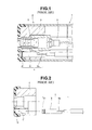
- FIG. 1 in addition to an LED light source unit 4 configuring an illuminating section, internal components such as an observation unit 5 and various fluid tubes 6 are attached to a distal end rigid member 3 configuring a distal end portion 2 of an endoscope 1 .
- the LED light source unit 4 is configured by including an LED ceramic substrate 8 on which an LED light source 41 is mounted. In the endoscope 1 , the size or the like of the LED ceramic substrate 8 configuring the LED light source unit 4 is limited.
- an escape portion 8 a such as a step or a cutout is formed on the LED ceramic substrate 8 .
- the LED light source unit 4 is assembled to an illumination disposing portion 11 as a recessed portion of a lens cover 10 fixed to the distal end rigid member 3 .
- the observation unit 5 is assembled to the distal end rigid member 3 , as shown in FIG. 3 .
- An endoscope includes: a distal end rigid portion that configures a distal end portion of an insertion portion of an endoscope and has a through hole; an LED ceramic substrate including an LED light source mounted on a distal end side thereof, the LED ceramic substrate being arranged in the through hole so as to emit light from the through hole; an LED cable configured to be inserted in the insertion portion of the endoscope and to supply electric power to the LED light source; a ceramic cutout portion that configures a proximal end side of the LED ceramic substrate, the ceramic cutout portion allowing a conductive pattern for electrically connecting the LED light source and the LED cable to be exposed from inside the LED ceramic substrate and connected to the LED cable; and a reinforcement member having rigidity, the reinforcement member being fixed to the LED ceramic substrate and configured to cover the ceramic cutout portion.
- FIGS. 1 to 3 relate to prior arts, in which FIG. 1 illustrates an LED light source unit, an observation unit and internal components which are provided at a distal end portion of an endoscope.
- FIG. 2 illustrates an LED unit assembling work
- FIG. 3 illustrates an observation unit assembling work.
- FIGS. 4-10 relate to an embodiment of the present invention, in which FIG. 4 illustrates a configuration of a distal end portion of an endoscope provided with an LED light source unit according to the present invention.
- FIG. 5 illustrates a configuration of the LED light source unit.
- FIG. 6 illustrates an LED unit assembling work in which the LED light source unit is assembled to a distal end rigid portion.
- FIG. 7 illustrates an observation unit assembling work in which the observation unit is assembled to the distal end rigid portion to which the LED light source unit is assembled.
- FIG. 8A illustrates a relationship between the distal end rigid portion to which the LED light source unit is assembled and the observation unit including an image pickup frame having a large diameter.
- FIG. 8B illustrates a state where the observation unit in FIG. 8A is assembled to the distal end rigid portion.
- FIG. 9A illustrates a configuration and working of a heat-radiation plate having a cutout portion.
- FIG. 9B illustrates the LED light source unit having a heat-radiation plate, which is seen from the direction of the arrow 9 B in FIG. 9A .
- FIG. 10 illustrates a configuration and working of a protection frame.
- a configuration of a distal end portion of an insertion portion of an endoscope will be described with reference to FIG. 4 .
- a distal end portion 21 of an insertion portion of an endoscope 20 is configured by including a distal end cover 22 and a distal end rigid portion 23 .
- the distal end cover 22 is made of an insulation member and the distal end rigid portion 23 is made of a metal member such as stainless steel.
- the distal end cover 22 is made of transparent resin member (made of polysulphone, for example) and formed in a cylindrical shape. On the distal end cover 22 , a rigid member through hole 24 , a nozzle through hole, and a treatment instrument through hole are formed. The distal end rigid portion 23 is disposed in the rigid member through hole 24 . A cleaning nozzle, not shown, is disposed in the nozzle through hole. The treatment instrument through hole configures a treatment instrument insertion hole, not shown.
- the reference numeral 25 represents an LED light source disposing hole.
- the LED light source disposing hole 25 is a recessed portion in which an LED light source 41 provided at the distal end portion of an LED light source unit 40 is disposed.
- the front face of the LED light source disposing hole 25 is configured as an illumination window 26 .
- the central axis of the rigid member through hole 24 , the central axis of the nozzle through hole, the central axis of the treatment instrument through hole, and the central axis of the LED light source disposing hole 25 are respectively parallel to the central axis of the distal end cover 22 .
- the distal end rigid portion 23 includes a projected portion 27 .
- the projected portion 27 is inserted and disposed in the rigid member through hole 24 .
- An observation unit through hole 28 an LED light source unit through hole 29 , air-feeding/water-feeding through hole (not shown), and the treatment instrument through hole (not shown) are formed at the distal end rigid portion 23 .
- An observation unit 30 is disposed in the observation unit through hole 28 .
- the LED light source unit 40 is disposed in the LED light source unit through hole 29 .
- the distal end side of the air-feeding/water-feeding through hole communicates with the nozzle through hole.
- An air-feeding tube and a water-feeding tube which are not shown, are connected to the proximal end side of the air-feeding/water-feeding through hole, through a tube ferrule (not shown).
- the treatment instrument through hole configures a treatment instrument insertion hole.
- the distal end side of the treatment instrument through hole communicates with the treatment instrument through hole of the distal end cover 22 .
- the proximal end side of the treatment instrument through hole is connected with a treatment instrument channel tube, not shown, through a channel ferrule (not shown).
- the central axis of the observation unit through hole 28 , the central axis of the LED light source unit through hole 29 , the central axis of air-feeding/water-feeding through hole, and the central axis of the treatment instrument through hole are parallel to the central axis of the distal end rigid portion 23 .
- the observation unit 30 is provided with a lens unit 31 and an image pickup apparatus 32 .
- the lens unit 31 is configured by including a lens frame 33 , and a plurality of optical members.
- the optical members include a plurality of optical lenses 34 , and the like arranged in the lens frame 33 .
- the lens frame 33 is made of a metal material which has excellent rigidity and corrosion-resistance, such as stainless steel.
- the image pickup apparatus 32 is configured by including an image pickup frame 35 , an image pickup section 36 , and a cover lens 37 .
- the image pickup section 36 is configured by a circuit substrate, not shown, on which an image pickup device 38 and electronic components are mounted.
- the image pickup device 38 is a CCD, a CMOS, or the like.
- the cover lens 37 is provided on the light-receiving surface side of the image pickup device 38 .
- the reference numeral 39 represents a signal cable and the signal cable is extended toward the operation portion.
- the image pickup frame 35 is made of a metal material which has excellent rigidity and corrosion-resistance, such as stainless steel.
- the configuration of the LED light source unit 40 is described with reference to FIGS. 4 and 5 .
- the LED light source unit 40 is configured by including the LED light source 41 , an LED ceramic substrate (hereinafter, shortly referred to as LED substrate) 42 , an LED cable 43 , a reinforcement member 44 , and a heat-radiation plate 45 .
- the LED substrate 42 is a ceramic substrate which has high heat conductivity and insulation property.
- the LED light source 41 includes, on one surface side thereof, one or a plurality of LEDs 41 a as a light-emitting portion.
- the LED light source 41 includes, on the other surface side thereof, a conductive portion 41 b.
- the LED substrate 42 has a rectangular parallelepiped shape, for example.
- the LED substrate 42 has, on the distal end side thereof, an LED light source holding portion (not shown).
- the conductive portion 41 b side of the LED light source 41 is disposed in the LED light source holding portion.
- a conductive pattern for electrically connecting the LED light source 41 and the LED cable 43 is provided inside the LED substrate 42 .
- the LED cable 43 for supplying electric power is inserted in the insertion portion of the endoscope 20 to be guided to the distal end portion 21 .
- a ceramic cutout portion (hereinafter shortly referred to as cutout portion) 46 is formed on the proximal end side of the LED substrate 42 .
- the LED substrate 42 on which the cutout portion 46 is formed has an L-shape including a first rectangular parallelepiped portion 42 a and a second rectangular parallelepiped portion 42 b .
- the first rectangular parallelepiped portion 42 a configures the distal end side and the second rectangular parallelepiped portion 42 b configures the proximal end side.
- the first rectangular parallelepiped portion 42 a is configured so as to have a predetermined thickness dimension.
- the second rectangular parallelepiped portion 42 b is so formed as to have a thickness dimension thinner than that of the first rectangular parallelepiped portion 42 a by the cutout portion 46 .
- the cutout portion 46 allows conductive patterns 47 a , 47 b to be exposed.
- a first core line 43 a of the LED cable 43 is arranged in the first conductive pattern 47 a exposed by the cutout portion 46 and electrically connected thereto, with soldering, not shown, for example.
- a second core line 43 b of the LED cable 43 is electrically connected to the second conductive pattern 47 b in a similar manner with soldering.
- first conductive pattern 47 a , the second conductive pattern 47 b , the first core line 43 a , and the second core line 43 b may be provided in plural numbers depending on the number of the LEDs 41 a provided to the LED light source 41 .
- the LED substrate 42 has a rectangular parallelepiped shape.
- the LED substrate 42 may have a prism shape, the cross-sectional shape of which is pentagon, hexagon, etc., or a cylindrical shape, the cross-sectional shape of which is round, ellipse, etc.
- the reinforcement member 44 is formed in a square U-shape with a predetermined thickness dimension.
- the reinforcement member 44 is made of a metal material having rigidity, such as stainless steel, for example.
- the reinforcement member 44 is integrally adhered and fixed to the LED substrate 42 using insulating adhesive, for example.
- the reinforcement member 44 is configured by including a lid surface 44 a and a pair of adhesive side surfaces 44 b .
- the inner surface of the lid surface 44 a is adhered and fixed onto a cutout-side one surface 42 c of the first rectangular parallelepiped portion 42 a of the LED substrate 42 .
- the inner surfaces of the pair of adhesive side surfaces 44 b are adhered and fixed to a pair of first side surfaces 42 d each of which is adjacent to the cutout side one surface 42 c , and adhered and fixed to a pair of second side surfaces 42 e of the second rectangular parallelepiped portion 42 b , which are the same surfaces as the first side surfaces 42 d.
- An insulative encapsulation resin or adhesive is filled in a space formed by the reinforcement member 44 which covers the cutout portion 46 and the second rectangular parallelepiped portion 42 b of the LED substrate 42 .
- the reinforcement member 44 and the second rectangular parallelepiped portion 42 b are integrally configured with the encapsulation resin or the adhesive.
- the insulative encapsulation resin or the adhesive prevents electric contact between the reinforcement member 44 and the core lines 43 a , 43 b.
- the heat-radiation plate 45 is formed with a metal material having high heat conductivity such as copper, or aluminum, or formed with a heat-conductive member configured by a material such as graphite that has an anisotropic nature in a heat-conductive direction.
- the thickness, width, and length of the heat-radiation plate 45 is appropriately set by taking the external dimension of the distal end portion 21 of the endoscope 1 , the heat radiation capacity, and the like into consideration.
- the cross-sectional shape of the heat-radiation plate 45 is a square U-shape.
- the heat-radiation plate 45 includes an adhesive portion 45 a and a cable fixing portion 45 b .
- the adhesive portion 45 a is brought into close contact with and fixed to the other surface 42 f which is rear surface of the cutout-side one surface 42 c of the first rectangular parallelepiped portion 42 a configuring the LED substrate 42 , for example.
- the cable fixing portion 45 b is previously protruded from a proximal end surface 42 g of the LED substrate 42 .
- the proximal end of the cable fixing portion 45 b is configured so as to be disposed in a distal-most bending piece 51 .
- a cable main body 43 c of the LED cable 43 is adhered and fixed to the cable fixing portion 45 b .
- the cross-sectional shape of the heat-radiation plate 45 is not limited to the square U-shape, but may be formed in a desired solid shape such as a plate shape, an L-shape, a U-shape, a semi-circular shape, or a box shape.
- the lid surface 44 a and the adhesive side surfaces 44 b of the reinforcement member 44 are thus adhered and fixed to the cutout-side one surface 42 c and the pair of first side surfaces 42 d of the first rectangular parallelepiped portion 42 a of the LED substrate 42 , and adhered and fixed to the pair of second side surfaces 42 e of the second rectangular parallelepiped portion 42 b , to cover the cutout portion 46 formed on the proximal end side of the LED substrate 42 .
- this configuration it is possible to prevent such a failure that a force in the Y 4 direction is accidentally applied to the cutout portion 46 .
- the cutout portion 46 of the LED substrate 42 is thus covered with the reinforcement member 44 made of metal member which has rigidity and which is formed in a predetermined thickness dimension, thereby capable of preventing breakage of the LED substrate 42 due to stress concentrating at the corner 46 a of the cutout portion 46 , without increasing the thickness dimension of the LED substrate 42 . As a result, it is possible to reduce the diameter of the distal end portion.
- the reinforcement member 44 of the LED light source unit 40 is disposed in the forward direction of the distal end rigid portion 23 than the image pickup frame 35 of the observation unit 30 , and the outer circumferential portion of the lid surface 44 a of the reinforcement member 44 covering the cutout portion 46 of the LED light source unit 40 is brought close to the lens frame 33 and arranged in the center direction of the distal end rigid portion 23 .
- the LED light source unit 40 is assembled to the central axis direction of the distal end rigid portion 23 so as to be located at a position where the LED cable 43 of the LED light source unit 40 does not interfere with the image pickup frame 35 of the observation unit 30 .
- the cable main body 43 c of the LED cable 43 is adhered and fixed to the heat-radiation plate 45 protruded from the proximal end surface of the LED substrate 42 .
- a cutout 45 d is provided for configuring a deform portion 45 c at a cable fixing portion 45 b of the heat-radiation plate 45 , as shown in FIGS. 9A and 9B .
- the deform portion 45 c deforms before a force in the arrow Y 9 direction acts on an adhered and fixed portion at which the first core line 43 a and the first conductive pattern 47 a are adhered and fixed and an adhered and fixed portion at which the second core line 43 b and the second conductive pattern 47 b are adhered and fixed, thereby relieving the force in the arrow Y 9 direction.
- a square U-shaped protection frame 52 made of stainless steel may be provided in a standing manner by making use of a vacant space of the distal end rigid portion 23 .
- the protection frame 52 is provided so as to be opposed to the cable fixing portion 45 b of the heat-radiation plate 45 .
- the protection frame 52 provided in a standing manner at the distal end rigid portion 23 is arranged in the distal-most bending piece 51 .
- the LED cable 43 is arranged between the protection frame 52 and the cable fixing portion 45 b without adhering and fixing the LED cable 43 to the cable fixing portion 45 b , thereby capable of surely preventing the unstable motion of the LED cable 43 .
Abstract
Description
Claims (7)
Applications Claiming Priority (3)
| Application Number | Priority Date | Filing Date | Title |
|---|---|---|---|
| JP2011-236389 | 2011-10-27 | ||
| JP2011236389 | 2011-10-27 | ||
| PCT/JP2012/076809 WO2013061838A1 (en) | 2011-10-27 | 2012-10-17 | Endoscope |
Related Parent Applications (1)
| Application Number | Title | Priority Date | Filing Date |
|---|---|---|---|
| PCT/JP2012/076809 Continuation WO2013061838A1 (en) | 2011-10-27 | 2012-10-17 | Endoscope |
Publications (2)
| Publication Number | Publication Date |
|---|---|
| US20130265798A1 US20130265798A1 (en) | 2013-10-10 |
| US8801255B2 true US8801255B2 (en) | 2014-08-12 |
Family
ID=48167671
Family Applications (1)
| Application Number | Title | Priority Date | Filing Date |
|---|---|---|---|
| US13/861,431 Active US8801255B2 (en) | 2011-10-27 | 2013-04-12 | Endoscope |
Country Status (5)
| Country | Link |
|---|---|
| US (1) | US8801255B2 (en) |
| EP (1) | EP2668892B1 (en) |
| JP (1) | JP5309274B1 (en) |
| CN (1) | CN103391741B (en) |
| WO (1) | WO2013061838A1 (en) |
Cited By (7)
| Publication number | Priority date | Publication date | Assignee | Title |
|---|---|---|---|---|
| US20160258582A1 (en) * | 2015-03-06 | 2016-09-08 | Schott Ag | Hermetically sealed led light and method for manufacturing a hermetically sealed led light |
| US20170108691A1 (en) * | 2015-10-15 | 2017-04-20 | Fujifilm Corporation | Endoscope |
| US10136803B1 (en) | 2018-04-26 | 2018-11-27 | InnovaQuartz LLC | Ring illuminated surgical camera |
| US10433710B1 (en) | 2018-05-22 | 2019-10-08 | Innovaquartz Inc. | In-vivo imaging and access system utilizing a canted working channel and a ring illuminated surgical camera |
| US10743756B2 (en) | 2018-10-11 | 2020-08-18 | InnovaQuartz LLC | Multi-spectrum ring illuminated surgical camera |
| US10952600B2 (en) | 2014-07-10 | 2021-03-23 | Covidien Lp | Endoscope system |
| US11931010B2 (en) | 2017-03-24 | 2024-03-19 | Covidien Lp | Endoscopes and methods of treatment |
Families Citing this family (8)
| Publication number | Priority date | Publication date | Assignee | Title |
|---|---|---|---|---|
| WO2017072861A1 (en) * | 2015-10-27 | 2017-05-04 | オリンパス株式会社 | Imaging device and endoscope |
| US9927113B2 (en) | 2016-05-26 | 2018-03-27 | Karl Storz Imaging, Inc. | Heat sink structure and LED heat sink assemblies |
| CN109106323B (en) * | 2018-08-31 | 2024-03-26 | 上海澳华内镜股份有限公司 | Endoscope illumination structure and endoscope |
| JP7150139B2 (en) * | 2019-03-18 | 2022-10-07 | オリンパス株式会社 | Light source and endoscope system |
| US11503989B2 (en) * | 2020-04-01 | 2022-11-22 | Opcom Inc. | Multi-channel system |
| TWI746377B (en) * | 2021-02-19 | 2021-11-11 | 晉弘科技股份有限公司 | Image sensor package and endoscope |
| JPWO2023017731A1 (en) | 2021-08-13 | 2023-02-16 | ||
| CN117396125A (en) | 2021-08-13 | 2024-01-12 | 豪雅株式会社 | Endoscope with a lens |
Citations (20)
| Publication number | Priority date | Publication date | Assignee | Title |
|---|---|---|---|---|
| US5429529A (en) * | 1993-03-08 | 1995-07-04 | Yazaki Corporation | Structure for connecting shielded-cable end |
| US5609561A (en) * | 1992-06-09 | 1997-03-11 | Olympus Optical Co., Ltd | Electronic type endoscope in which image pickup unit is dismounted to execute disinfection/sterilization processing |
| US6036636A (en) * | 1996-11-18 | 2000-03-14 | Olympus Optical Co., Ltd. | Endoscope with tip portion disposed on distal side of insertion portion |
| JP2002051971A (en) | 2000-08-14 | 2002-02-19 | Asahi Optical Co Ltd | Endoscope |
| US6371907B1 (en) * | 1996-11-18 | 2002-04-16 | Olympus Optical Co., Ltd. | Endoscope apparatus driving manipulation wires with drive motor in drum portion |
| US6488619B1 (en) * | 1998-09-08 | 2002-12-03 | Olympus Optical Co., Ltd. | Distal endoscope part having light emitting source such as light emitting diodes as illuminating means |
| US20030050534A1 (en) * | 2001-09-07 | 2003-03-13 | Yuri Kazakevich | Endoscopic system with a solid-state light source |
| JP2005077858A (en) | 2003-09-01 | 2005-03-24 | Matsushita Electric Ind Co Ltd | Optical module, optical transmission device, and optical transmission system |
| JP2006068057A (en) * | 2004-08-31 | 2006-03-16 | Pentax Corp | Distal end portion of electronic endoscope |
| US20060183977A1 (en) * | 2003-10-06 | 2006-08-17 | Olympus Corporation | Endoscope |
| US20070191684A1 (en) * | 2004-10-24 | 2007-08-16 | Yasuo Hirata | Endoscope device |
| US20080300457A1 (en) * | 2003-10-06 | 2008-12-04 | Olympus Corporation | Endoscope |
| US20090030274A1 (en) * | 2006-09-15 | 2009-01-29 | Acclarent, Inc. | Endoscopic methods and devices for transnasal procedures |
| JP2009022588A (en) | 2007-07-20 | 2009-02-05 | Olympus Medical Systems Corp | Illuminating apparatus and endoscope equipped with the same |
| US20090177038A1 (en) * | 2007-12-27 | 2009-07-09 | Fujifilm Corporation | Electronic endoscope |
| US20100188493A1 (en) * | 2009-01-23 | 2010-07-29 | Kazuhiro Kanzaki | Endoscope adapter including light emitting diode, and adapter type endoscope |
| US20100261961A1 (en) * | 2006-12-21 | 2010-10-14 | Intuitive Surgical Operations, Inc. | Hermetically sealed distal sensor endoscope |
| US20110230722A1 (en) * | 2010-01-28 | 2011-09-22 | Olympus Medical Systems Corp. | Illumination unit, endoscope having illumination unit and illumination probe having illumination unit which is inserted into endoscopic channel |
| US20110306834A1 (en) * | 2010-06-11 | 2011-12-15 | Stephan Schrader | Endoscope |
| US20120002394A1 (en) * | 2005-01-28 | 2012-01-05 | Stryker Corporation | Disposable attachable light source unit for an endoscope |
Family Cites Families (2)
| Publication number | Priority date | Publication date | Assignee | Title |
|---|---|---|---|---|
| JPH11267099A (en) * | 1998-03-24 | 1999-10-05 | Olympus Optical Co Ltd | Endoscope |
| JP2008048905A (en) * | 2006-08-24 | 2008-03-06 | Olympus Medical Systems Corp | Endoscope apparatus |
-
2012
- 2012-10-17 EP EP12844480.9A patent/EP2668892B1/en not_active Not-in-force
- 2012-10-17 WO PCT/JP2012/076809 patent/WO2013061838A1/en active Application Filing
- 2012-10-17 CN CN201280009991.9A patent/CN103391741B/en not_active Expired - Fee Related
- 2012-10-17 JP JP2013515618A patent/JP5309274B1/en active Active
-
2013
- 2013-04-12 US US13/861,431 patent/US8801255B2/en active Active
Patent Citations (22)
| Publication number | Priority date | Publication date | Assignee | Title |
|---|---|---|---|---|
| US5609561A (en) * | 1992-06-09 | 1997-03-11 | Olympus Optical Co., Ltd | Electronic type endoscope in which image pickup unit is dismounted to execute disinfection/sterilization processing |
| US5429529A (en) * | 1993-03-08 | 1995-07-04 | Yazaki Corporation | Structure for connecting shielded-cable end |
| US6036636A (en) * | 1996-11-18 | 2000-03-14 | Olympus Optical Co., Ltd. | Endoscope with tip portion disposed on distal side of insertion portion |
| US6371907B1 (en) * | 1996-11-18 | 2002-04-16 | Olympus Optical Co., Ltd. | Endoscope apparatus driving manipulation wires with drive motor in drum portion |
| US6488619B1 (en) * | 1998-09-08 | 2002-12-03 | Olympus Optical Co., Ltd. | Distal endoscope part having light emitting source such as light emitting diodes as illuminating means |
| JP2002051971A (en) | 2000-08-14 | 2002-02-19 | Asahi Optical Co Ltd | Endoscope |
| US20030050534A1 (en) * | 2001-09-07 | 2003-03-13 | Yuri Kazakevich | Endoscopic system with a solid-state light source |
| US6692431B2 (en) * | 2001-09-07 | 2004-02-17 | Smith & Nephew, Inc. | Endoscopic system with a solid-state light source |
| JP2005077858A (en) | 2003-09-01 | 2005-03-24 | Matsushita Electric Ind Co Ltd | Optical module, optical transmission device, and optical transmission system |
| US20060183977A1 (en) * | 2003-10-06 | 2006-08-17 | Olympus Corporation | Endoscope |
| US20080300457A1 (en) * | 2003-10-06 | 2008-12-04 | Olympus Corporation | Endoscope |
| JP2006068057A (en) * | 2004-08-31 | 2006-03-16 | Pentax Corp | Distal end portion of electronic endoscope |
| US20070191684A1 (en) * | 2004-10-24 | 2007-08-16 | Yasuo Hirata | Endoscope device |
| US20120002394A1 (en) * | 2005-01-28 | 2012-01-05 | Stryker Corporation | Disposable attachable light source unit for an endoscope |
| US20090030274A1 (en) * | 2006-09-15 | 2009-01-29 | Acclarent, Inc. | Endoscopic methods and devices for transnasal procedures |
| US20100261961A1 (en) * | 2006-12-21 | 2010-10-14 | Intuitive Surgical Operations, Inc. | Hermetically sealed distal sensor endoscope |
| JP2009022588A (en) | 2007-07-20 | 2009-02-05 | Olympus Medical Systems Corp | Illuminating apparatus and endoscope equipped with the same |
| US20090177038A1 (en) * | 2007-12-27 | 2009-07-09 | Fujifilm Corporation | Electronic endoscope |
| US20100188493A1 (en) * | 2009-01-23 | 2010-07-29 | Kazuhiro Kanzaki | Endoscope adapter including light emitting diode, and adapter type endoscope |
| US20110230722A1 (en) * | 2010-01-28 | 2011-09-22 | Olympus Medical Systems Corp. | Illumination unit, endoscope having illumination unit and illumination probe having illumination unit which is inserted into endoscopic channel |
| US8333694B2 (en) * | 2010-01-28 | 2012-12-18 | Olympus Medical Systems Corp. | Illumination unit, endoscope having illumination unit and illumination probe having illumination unit which is inserted into endoscopic channel |
| US20110306834A1 (en) * | 2010-06-11 | 2011-12-15 | Stephan Schrader | Endoscope |
Cited By (13)
| Publication number | Priority date | Publication date | Assignee | Title |
|---|---|---|---|---|
| US11219359B2 (en) | 2014-07-10 | 2022-01-11 | Covidien Lp | Endoscope system |
| US10952600B2 (en) | 2014-07-10 | 2021-03-23 | Covidien Lp | Endoscope system |
| US10890318B2 (en) * | 2015-03-06 | 2021-01-12 | Schott Ag | Hermetically sealed LED light and method for manufacturing a hermetically sealed LED light |
| US11933485B2 (en) | 2015-03-06 | 2024-03-19 | Schott Ag | Hermetically sealed LED light and method for manufacturing a hermetically sealed LED light |
| US20160258582A1 (en) * | 2015-03-06 | 2016-09-08 | Schott Ag | Hermetically sealed led light and method for manufacturing a hermetically sealed led light |
| US10281711B2 (en) * | 2015-10-15 | 2019-05-07 | Fujifilm Corporation | Endoscope with retention member |
| US20170108691A1 (en) * | 2015-10-15 | 2017-04-20 | Fujifilm Corporation | Endoscope |
| US11931010B2 (en) | 2017-03-24 | 2024-03-19 | Covidien Lp | Endoscopes and methods of treatment |
| US10413166B1 (en) | 2018-04-26 | 2019-09-17 | Innovaquartz Inc. | Ring illuminated surgical camera |
| US10136803B1 (en) | 2018-04-26 | 2018-11-27 | InnovaQuartz LLC | Ring illuminated surgical camera |
| US10433710B1 (en) | 2018-05-22 | 2019-10-08 | Innovaquartz Inc. | In-vivo imaging and access system utilizing a canted working channel and a ring illuminated surgical camera |
| US10743756B2 (en) | 2018-10-11 | 2020-08-18 | InnovaQuartz LLC | Multi-spectrum ring illuminated surgical camera |
| US10743755B1 (en) | 2018-10-11 | 2020-08-18 | InnovaQuartz LLC | Multi-spectrum ring illuminated surgical camera |
Also Published As
| Publication number | Publication date |
|---|---|
| CN103391741A (en) | 2013-11-13 |
| EP2668892B1 (en) | 2016-01-06 |
| WO2013061838A1 (en) | 2013-05-02 |
| EP2668892A4 (en) | 2014-09-24 |
| JPWO2013061838A1 (en) | 2015-04-02 |
| EP2668892A1 (en) | 2013-12-04 |
| CN103391741B (en) | 2015-12-09 |
| JP5309274B1 (en) | 2013-10-09 |
| US20130265798A1 (en) | 2013-10-10 |
Similar Documents
| Publication | Publication Date | Title |
|---|---|---|
| US8801255B2 (en) | Endoscope | |
| EP2594187B1 (en) | Endoscope | |
| US10972707B2 (en) | Endoscope and method of manufacturing endoscope | |
| US11653825B2 (en) | Imaging unit and oblique-viewing endoscope | |
| JP2007044350A (en) | Endoscope | |
| JP7078798B2 (en) | Endoscope connector device | |
| JP2011200401A (en) | Endoscope | |
| JP4709661B2 (en) | Imaging device | |
| JP5738645B2 (en) | Endoscope | |
| US20200110257A1 (en) | Imaging unit and endoscope | |
| JP6995659B2 (en) | Imaging modules, endoscopes, and catheters | |
| CN109068964B (en) | Cable connection structure, image pickup apparatus, and endoscope | |
| JP7251940B2 (en) | strabismus endoscope | |
| WO2020121435A1 (en) | Endoscope tip and endoscope | |
| JP4989050B2 (en) | Endoscopy adapter and endoscope | |
| JP2001311879A (en) | Endoscope and its manufacturing method | |
| US20170325665A1 (en) | Illuminator Circuit Board Assembly for An Endoscope | |
| JP7385736B2 (en) | Endoscope imaging device | |
| WO2016203535A1 (en) | Endoscope | |
| CA3097536C (en) | Flexible light guide and heat sink for endoscopic systems | |
| US10401612B2 (en) | Endoscope | |
| JP3188382U (en) | Endoscope | |
| JP2022166635A (en) | endoscope camera head | |
| JP2014124214A (en) | Illumination unit and side view type endoscope including the illumination unit | |
| JPH11276433A (en) | Electronic endoscope |
Legal Events
| Date | Code | Title | Description |
|---|---|---|---|
| AS | Assignment |
Owner name: OLYMPUS MEDICAL SYSTEMS CORP., JAPAN Free format text: ASSIGNMENT OF ASSIGNORS INTEREST;ASSIGNOR:KUDO, AKIRA;REEL/FRAME:030676/0695 Effective date: 20130603 |
|
| STCF | Information on status: patent grant |
Free format text: PATENTED CASE |
|
| FEPP | Fee payment procedure |
Free format text: PAYOR NUMBER ASSIGNED (ORIGINAL EVENT CODE: ASPN); ENTITY STATUS OF PATENT OWNER: LARGE ENTITY |
|
| AS | Assignment |
Owner name: OLYMPUS CORPORATION, JAPAN Free format text: ASSIGNMENT OF ASSIGNORS INTEREST;ASSIGNOR:OLYMPUS MEDICAL SYSTEMS CORP.;REEL/FRAME:036276/0543 Effective date: 20150401 |
|
| AS | Assignment |
Owner name: OLYMPUS CORPORATION, JAPAN Free format text: CHANGE OF ADDRESS;ASSIGNOR:OLYMPUS CORPORATION;REEL/FRAME:039344/0502 Effective date: 20160401 |
|
| MAFP | Maintenance fee payment |
Free format text: PAYMENT OF MAINTENANCE FEE, 4TH YEAR, LARGE ENTITY (ORIGINAL EVENT CODE: M1551) Year of fee payment: 4 |
|
| MAFP | Maintenance fee payment |
Free format text: PAYMENT OF MAINTENANCE FEE, 8TH YEAR, LARGE ENTITY (ORIGINAL EVENT CODE: M1552); ENTITY STATUS OF PATENT OWNER: LARGE ENTITY Year of fee payment: 8 |