US8805989B2 - Business continuity on cloud enterprise data centers - Google Patents
Business continuity on cloud enterprise data centers Download PDFInfo
- Publication number
- US8805989B2 US8805989B2 US13/531,744 US201213531744A US8805989B2 US 8805989 B2 US8805989 B2 US 8805989B2 US 201213531744 A US201213531744 A US 201213531744A US 8805989 B2 US8805989 B2 US 8805989B2
- Authority
- US
- United States
- Prior art keywords
- cloud
- customer
- continuity
- service
- production
- Prior art date
- Legal status (The legal status is an assumption and is not a legal conclusion. Google has not performed a legal analysis and makes no representation as to the accuracy of the status listed.)
- Active
Links
- 238000012545 processing Methods 0.000 claims abstract description 23
- 238000004519 manufacturing process Methods 0.000 claims description 44
- 230000010076 replication Effects 0.000 claims description 31
- 238000011084 recovery Methods 0.000 claims description 24
- 238000000034 method Methods 0.000 claims description 14
- 238000012360 testing method Methods 0.000 claims description 9
- 238000004891 communication Methods 0.000 claims description 4
- 230000000007 visual effect Effects 0.000 claims 1
- 238000005516 engineering process Methods 0.000 description 9
- 238000010586 diagram Methods 0.000 description 7
- 230000006870 function Effects 0.000 description 6
- 230000008569 process Effects 0.000 description 3
- 230000003362 replicative effect Effects 0.000 description 3
- 230000001052 transient effect Effects 0.000 description 3
- 238000004590 computer program Methods 0.000 description 2
- 238000012546 transfer Methods 0.000 description 2
- 230000003213 activating effect Effects 0.000 description 1
- 230000004931 aggregating effect Effects 0.000 description 1
- 230000009286 beneficial effect Effects 0.000 description 1
- 230000008859 change Effects 0.000 description 1
- 230000003993 interaction Effects 0.000 description 1
- 238000002955 isolation Methods 0.000 description 1
- 230000007246 mechanism Effects 0.000 description 1
- 238000012544 monitoring process Methods 0.000 description 1
- 230000006855 networking Effects 0.000 description 1
- 230000003287 optical effect Effects 0.000 description 1
- 230000002093 peripheral effect Effects 0.000 description 1
- 230000007704 transition Effects 0.000 description 1
Images


Classifications
-
- G—PHYSICS
- G06—COMPUTING; CALCULATING OR COUNTING
- G06F—ELECTRIC DIGITAL DATA PROCESSING
- G06F9/00—Arrangements for program control, e.g. control units
- G06F9/06—Arrangements for program control, e.g. control units using stored programs, i.e. using an internal store of processing equipment to receive or retain programs
- G06F9/46—Multiprogramming arrangements
- G06F9/50—Allocation of resources, e.g. of the central processing unit [CPU]
- G06F9/5061—Partitioning or combining of resources
- G06F9/5077—Logical partitioning of resources; Management or configuration of virtualized resources
-
- G—PHYSICS
- G06—COMPUTING; CALCULATING OR COUNTING
- G06F—ELECTRIC DIGITAL DATA PROCESSING
- G06F9/00—Arrangements for program control, e.g. control units
- G06F9/06—Arrangements for program control, e.g. control units using stored programs, i.e. using an internal store of processing equipment to receive or retain programs
- G06F9/46—Multiprogramming arrangements
- G06F9/50—Allocation of resources, e.g. of the central processing unit [CPU]
- G06F9/5061—Partitioning or combining of resources
- G06F9/5072—Grid computing
Definitions
- VDCs Virtual Data Centers
- IaaS infrastructure-as-a-service
- Server virtualization decouples physical hardware from the operating system and other information technology and resources. Server virtualization allows multiple virtual machines with different operating systems and applications to run in isolation side by side on the same physical machine.
- a virtual machine is a software representation of a physical machine, specifying its own set of virtual hardware resources such as processors, memory, storage, network interfaces, and so forth upon which an operating system and applications are run.
- cloud service providers are offering additional value-added services to IaaS customers as a way of retaining existing customers and attracting new ones.
- Services being offered to customers include, for example, business continuity services. These services are optional but subscribing to them may be beneficial to the use and operation of each individual VDC.
- Subscribing to a business continuity service helps protects virtual machines operating in the customer's VDC from interruptions in the availability of the service providers' infrastructure.
- the service provider can now respond to a disaster at the primary site, such as a network outage or power failure, by transitioning customer systems to run out of a secondary site, thereby minimizing the disruption to application availability.
- This transition known as a “fail over”, can be done on a per-customer, per-VDC, or per-VM basis.
- business continuity services are implemented in a more orderly fashion from the perspective of the service provider and the cloud customer.
- a data processing system for hosting virtual machines in a cloud computing environment.
- a primary production cloud site operated from a first location, provides a set of virtual machines to a set of customers.
- a second production site operates at a second location. The second location also operates as a continuity production cloud for the set of customers.
- a cloud management service both (a) maintains configuration of the set of virtual machines as one or more Virtual Data Centers (VDCs); and (b) permits selective enablement of a business continuity service for failing over selected elements of the production cloud to the continuity production cloud on a per-customer, per-VDC, or per-VM basis.
- VDCs Virtual Data Centers
- additional features may include:
- VDCs virtual data processors, firewalls, load balancers, and virtual local area networks as elements of the VDCs;
- a replication service provides data replication between the first and second locations
- a network interface provides secure communication between the production and continuity clouds, such that the first customer is prevented from accessing production or continuity clouds provided for other customers;
- the replication service operating independently of the production cloud and the continuity cloud.
- the cloud management service can further enable the first customer to specify Service Level Agreement (SLA) information including one or more of cost, Recovery Point Objective (RPO) and Recovery Time Objective (RTO).
- SLA Service Level Agreement
- RPO Recovery Point Objective
- RTO Recovery Time Objective
- the cloud management service can also further enable the first customer to specify which one of several possible data processing platforms at several locations are to provide the target production cloud for the first user.
- the first customer in the event of a disaster;
- a recover plan is executed for each continuity enabled VDC to bring online VMs as specified by the user in an order of recovery;
- a recover plan is executed for each continuity enabled VDC to bring online VMs as specified by the user in an order of recovery;
- DNS updates are initiated for the recovered VM's.
- FIG. 1 is a high level diagram of a service provider who offers enterprise cloud services with optional business continuity to a number of customers.
- FIG. 2 illustrates a Virtual Data Center (VDC) in more detail.
- VDC Virtual Data Center
- FIG. 3 is a data structure maintained by the service provider to represent information concerning which VDCs have associated business continuity services enabled.
- FIG. 4 illustrates replication services implemented between various sites.
- FIG. 5 shows a result of operating replication services is to store VDC replicas at failover sites.
- FIG. 6 shows the state immediately after an outage at cloud site one.
- FIG. 7 illustrates the state after the backup VDC images are promoted to production mode.
- FIG. 8 illustrates an initial state one a cloud site is brought back on line.
- FIG. 9 is an intermediate state after the cloud site is brought online but where some of the VDCs are still serviced from the backup site.
- FIG. 10 is the state after all VDCs are again active at the original site.
- FIG. 11 shows the cloud management database in more detail.
- FIG. 12 illustrates detail of how replication occurs between two sites.
- FIG. 13 is an example user interface for specifying business continuity options.
- FIG. 14 is a user interface for configuring a virtual data center in the enterprise cloud.
- FIG. 15 illustrates a sequence of steps performed in the event of a disaster.
- FIG. 16 illustrates a sequence of steps performed at time of test.
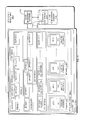
- FIG. 1 is a high level diagram of a typical cloud based information technology (IT) environment 100 in which improved business continuity procedures and apparatus described herein may be used. It should be understood that this is but one example cloud environment and many others are possible.
- IT information technology
- the business continuity service allows for site-to-site recovery across multiple data centers that can be placed at geographically diverse sites.
- SLA service level agreement
- the customer may specify a Recovery Time Objective (RTO) and Recovery Point Objective (RPO).
- RTO Recovery Time Objective
- RPO Recovery Point Objective
- the business continuity service is made available to customers on a per VDC basis.
- the customer specifies configuration of his VDC (including any virtual machines, firewalls, load balancers, etc.) he can then treat his entire VDC configuration as a single entity to which continuity services are applied.
- the service provider is then entirely responsible for configuring the details of replicating the VDC, managing that data that specifies the replication, isolating that detail from the customer, and bring the VDC back on line at the time of a disaster. Examples of conditions under which a disaster might be declared could include a network outage, power outage, or complete site failure.
- the cloud environment 100 illustrated in FIG. 1 is operated by a cloud service provider.
- the environment 100 includes equipment located at several different physical locations or sites 102 .
- a first cloud site 102 - 1 may be located in Philadelphia, Pennsylvania, USA
- a second cloud site 102 - 2 may be located in London, England, UK
- a third cloud site 102 - 3 may be located in Vietnamese, Maharashtra, India.
- An example cloud site 102 is responsible for hosting infrastructure equipment that provides cloud services to many different customers.
- cloud site 102 - 1 there are n customers 104 - 1 - 1 through 104 - 1 -n.
- Cloud site 102 - 2 is servicing m customers 104 - 2 - 1 , . . . , 104 - 2 -m, and cloud site 102 - 3 hosts p customers 104 - 3 - 1 , . . . , 104 - 3 -p.
- VDC 110 One type of cloud service provided is a Virtual Data Center (VDC) 110 .
- An example VDC 110 may include many different types of virtual data processing resources such as virtual firewalls, virtual load balancers, virtual local area networks, virtual data processing machines, virtual memory, virtual disk storage, and software resources such as operating systems and applications. It should also be understood that although an example customer one 104 - 1 - 1 shown in FIG. 1 appears to have specified exactly four (4) VDCs ( 110 - 1 - 1 - 1 , 110 - 1 - 1 - 2 , . . . , 110 - 1 - 1 -n) in reality any given customer 104 - 1 - 1 , . . . , 104 - 3 -p may have more or less than the four VDCs than are illustrated in FIG. 1 .
- the VDCs 110 - 1 served from site one 102 - 1 for customer one 104 - 1 serve as a production cloud for specific customers 104 - 1 - 1 , 104 - 1 - 2 , . . . , 104 - 1 -n.
- the VDCs 110 - 1 served from site two 102 - 2 for other customers 104 - 2 - 1 , 104 - 2 - 2 , . . . , 104 - 2 -m serve as a production cloud for those other customers 104 - 2 - 1 , 104 - 2 - 2 , . . . , 104 - 2 -m.
- the VDCs 110 include virtual computing resources that are physically implemented at each particular service provider site 102 but are remotely accessed by the respective customers 104 over network connection(s).
- the service provider thus operates a number of physical machines at the various provider sites 102 - 1 , 102 - 2 , 102 - 3 including networking equipment such as switches, routers, and other types internetworking equipment such as physical firewalls, and multiple physical data processors, storage servers, storage area networks, and other data processing machines as needed to provide the functions required by the VDCs 110 .
- networking equipment such as switches, routers, and other types internetworking equipment such as physical firewalls, and multiple physical data processors, storage servers, storage area networks, and other data processing machines as needed to provide the functions required by the VDCs 110 .
- the details of configuration and operation of this physical data processing equipment are hidden from the customers 104 ; this data processing model sometimes referred to as Infrastructure as a Service (IaaS).
- IaaS Infrastructure as a Service
- An administrative user typically associated with each service customer 104 does however have access to a cloud management function 120 at one or more sites 102 .
- the cloud management interface allows administrative users to interact with and configure the elements of their VDCs available to them from the cloud site 102 as well as additional services.
- Cloud management components at least some of which are located each cloud site 102 may also be provided from a central location (not shown in FIG. 1 ).
- the service provider may allow each customer to use the cloud management interface 120 to specify policies or other services on a per customer, per VDC or per virtual machine basis.
- An example of a custom service policy might be a backup policy that schedules backups of all virtual machines (VMs) at a given time each day for example at midnight Pacific Standard Time (PST) each day.
- VMs virtual machines
- PST Pacific Standard Time
- the business continuity service offered by the service provider in the environment 100 allows each customer to specify optional services to be provided on a per VDC 110 basis.
- One of the services of interest is a business continuity service that enables a selected VDC to be brought back on line at an alternate site 102 - 2 , 102 - 3 in the event that a selected cloud site 102 - 1 fails, goes off-line, or otherwise becomes unavailable.
- a typical VDC is shown in more detail in FIG. 2 , and includes a number of virtual machines 201 - 1 , 201 - 2 , 201 - 3 , . . . , 201 -n.
- An example VM 201 has associated with it a network address such as an Internet Protocol (IP), an operating system 203 , and one or more applications 204 .
- IP Internet Protocol
- the VMs 201 may be further interconnected into one or more Virtual Local Area Networks (VLANs) 210 - 1 , 210 - 2 .
- VLANs Virtual Local Area Networks
- FIG. 2 illustrates a single operating system 203 and single application 204 for each VM 201 it should be understood that multiple operating systems 203 and multiple applications 204 may be implemented in each VM 201 .
- the example VDC 110 also may have one or more virtual firewalls 212 , virtual load balancers 221 and other services 230 .
- Virtual firewalls 211 - 1 and 211 - 2 may each have a number of associated policies 212 - 1 - 1 , . . . 212 - 2 -m.
- the virtual load balancers 220 - 1 and 220 - 2 also have associated policies 221 - 1 - 1 through 221 - 2 -m.
- the services 230 associated with each VDC 110 are selectively chosen by the customer and specified via cloud management 120 .
- the service provider may choose to charge additional fees for activating these optional services.
- a given VDC 110 may have a backup policy 230 - 1 , and operating system patching policy 230 - 2 , and monitoring policies 230 - 3 .
- the customer can specify a business continuity (BC) policy 230 - 4 on a per-VDC basis.
- BC business continuity
- FIG. 3 is a high-level conceptual diagram of an example cloud site one 102 - 1 and how the customers 104 - 1 - 1 , 104 - 1 - 2 , 104 - 1 - 3 , and 104 - 1 -n it is responsible for have specified business continuity services for each of their respective VDCs.
- customer one 104 - 1 - 1 of cloud site one 102 - 1 has specified that business continuity services should be enabled for his VDC 1 ( 110 - 1 - 1 - 1 ) and his VDC 4 ( 110 - 1 - 1 - 4 ) but not for his other VDC 2 , VDC 3 , and VDC n.
- customer two 104 - 1 - 2 has specified that business continuity services should be enabled for his VDC 2 ( 110 - 1 - 2 - 2 ) but not for any of his other VDC 1 , VDC 3 , VDC 4 , . . . , or VDC m.
- each customer 102 specifies, on a per VDC basis, and not on a lower level (such as a per-VM basis) or on a high level (such as a per customer basis), the enablement of business continuity services.
- FIG. 4 is a diagram similar to that of FIG. 1 but illustrating that to provide the requested business continuity services there are replication services put in place between the various cloud sites 102 .
- a first replication service 400 - 1 - 2 operates to replicate information between site one 102 - 1 - 2 and site two 102 - 2
- a second replication service 400 - 2 - 3 replicates data between site two 102 - 2 and site three 102 - 3
- a third replication service 400 - 1 - 3 replicates data between site one 102 - 1 and site three 102 - 3 .
- These replication services can be implemented using any convenient replication technology, but operate independently of the customers 104 and other operations of the sites 102 .
- FIG. 5 shows the outcome of implementing these replication services.
- customer one 104 - 1 has requested that his VDC 1 and VDC 4 have business continuity services enabled; likewise customer two 104 - 2 has requested that only his VDC 4 be subjected to the business continuity service.
- replication services 400 - 1 - 2 and 400 - 1 - 3 the VDC 1 and VDC 4 belonging to customer one 104 - 1 at cloud site one 102 - 1 will eventually be replicated at cloud site two 102 - 2 .
- another customer n 104 -n of site one 102 - 1 will have his VDC 4 replicated at site two 102 - 2 .
- FIG. 5 shows the outcome of implementing these replication services.
- site one 102 - 1 has a customer two 104 - 1 - 2 that has requested business continuity services for his VDC 2 , but that site three 102 - 3 be used for this. So the replication service 400 - 1 - 3 causes an image of his VDC 2 to be created at site three 102 - 3 as VDC image 110 - 3 - 1 - 2 .
- VDCs ( 110 - 2 - 1 - 1 - 1 , 110 - 2 - 1 - 1 - 4 and 110 - 2 - 1 -n- 4 ) will exist as images (e.g., as replicas or dormant copies) and will not yet be in an active production mode; this fact is indicated by the use of dashed lines in FIG. 5 . As with the prior figures, the VDC shown with solid lines are used to indicate that those VDCs are in an active production mode.
- site one 102 - 1 serves as a production cloud for customer one
- customer one also has access to one or more other sites, such as site two 102 - 2 .
- These other sites serve as a business continuity cloud for customer one from which selected VDCs will be served in the event of a failure at site one.
- These other sites also serve as primary production clouds for other customers at the same time.
- customers can specify at which site their respective business continuity elements are located; this option can be specified on the same user interface screen when the administrative user specifies the configuration of his corresponding business continuity services for each VDC.
- a customer can specify further aspects of the business continuity service such as Recovery Time Objective (RTO) and Recovery Point Objective (RPO), according to an available Agreement (SLA) entered into between the customer and the service provider.
- RTO Recovery Time Objective
- RPO Recovery Point Objective
- SLA available Agreement
- site one 102 - 1 is now experiencing an outage 601 of some type that makes it unavailable to customer one 104 - 1 and other customers.
- cloud site one 102 - 1 goes down, these associated customers may be notified of the outage in a manner that has been pre-arranged such as by e-mail, mobile text message, phone call etc.
- VDCs 110 - 2 - 1 - 1 - 1 , 110 - 2 - 1 - 1 - 4 , . . . , 110 - 2 -n- 1 - 4 , 110 - 3 - 1 - 2 - 2 are brought back online at the respective alternate sites 102 - 2 , 102 - 3 .
- site one 102 - 1 again comes back online.
- site one 102 - 1 is not yet hosting any production VDCs as it does not yet have access to the information needed to bring them back online, and therefore customer one 104 - 1 and customer two 104 - 2 continue to have their VDCs hosted from the alternate locations 102 - 2 , 102 - 3 .
- VDCs shown with the solid lines (e.g., VDC 2 and VDC 3 for site one's is customer one 104 - 1 - 1 , VDC 1 , VDC 3 and VDC 4 for site one's customer two 104 - 1 - 2 , and VDC 1 , VDC, 2 , VDC 3 , for site one's customer n 104 - 1 -n, etc.) are thus brought into production mode in this state.
- VDCs for which business continuity was selected are however still not yet brought in production mode on site one 102 - 1 but remain as images. These must first be brought over via the replication service 400 - 1 - 2 , 400 - 1 - 3 as replicas or images from the corresponding locations at which they have continued to operate in production mode during the outage of site one 102 - 1 .
- FIG. 10 illustrates a state where the VDCs for customer one are again in production mode on site one 102 - 1 and the corresponding images can remain in the dormant state on site two 102 - 2 .
- customer two 102 - 2 and customer n 102 -n is again actively serviced from site one 102 - 1 , and their respective sets of VDC images ( 110 - 3 - 1 - 2 - 2 and 110 - 2 - 1 -n- 4 ) are being maintained as copies in the backup sites 102 - 2 , 1023 .
- Replication services will again maintain these images as changes are made to the corresponding production VDCs according to the service-level agreements in place.
- FIG. 11 is a more detailed view of the cloud management function 120 - 1 deployed at typical cloud site one 102 - 1 .
- One set of information maintained by cloud management 120 - 1 is the configuration and policy data 1114 - 1 , . . . , 1114 -n associated with each customer 104 - 1 , . . . , 104 -n serviced by site 102 - 1 .
- the configuration data includes information concerning the configuration of the customer's virtual machines, such as initial configuration information, for each machine in each VDC specified by that customer.
- the policy data concerns the configuration details for the firewalls, load balancers, and other machines in the VDC that require policy-based configuration, as well as selected service policies specified by the customer.
- Information stored in the cloud configuration database 1112 is obtained using various user interfaces that will be described below.
- FIG. 12 illustrates in more detail how replication service 400 - 1 - 2 may operate to replicate data from cloud site one 102 - 1 to site two 102 - 2 .
- configuration and policy data for the various VDCs is replicated separately from the virtual machine state information.
- the two different replication functions can be performed by two different replication technologies.
- a virtual machine replication technology 1220 can be responsible for replicating virtual machine definition files between the cloud sites; keeping in mind that this is performed on a per VDC basis as specified by the customer policies stored in configuration policy database 1112 - 1 .
- a database replication technology 1210 is responsible for replicating the policy information (which typically changes on a much less frequent basis than the VM state information).
- FIG. 13 shows a screenshot of an example cloud service dashboard that presents a set of services that are available to customers, and information related to the services.
- a customer logs into the cloud configuration manager 120 - 1 at his primary site 102 - 1 (e.g., by entering a username and password).
- the cloud manager 120 then provides access to a cloud service dashboard for a VDC employed by the customer.
- One of the offered services is a “business continuity” service; in the example shown, the offered service is shown as graphical icon accompanied by an empty checkbox and the text “disabled.”
- the cloud service dashboard also shows other subscribed services called “load balancing” and “firewall,” respectively, to the customer.
- the cloud service dashboard for each service shown by the cloud service dashboard, the cloud service dashboard also shows a customer the terms and conditions of an associated Service Level Agreement (SLA) that specifies the RPO and RTO that will dictate operation of the replication and recovery processes described above.
- SLA Service Level Agreement
- the cloud service dashboard may send copies of the service level agreements to the customer so that the customer can view them later in time.
- the cloud service dashboard is provided to the customer as a webpage.
- the webpage may be transmitted to the customer from a server residing in a management network operated by the cloud service provider.
- the cloud service dashboard shows that the customer has successfully subscribed to the business continuity service such as by showing a filled-in checkbox and accompanying text “enabled”.
- FIG. 14 is an example user interface screen where the configuration of a VDC 110 may be specified.
- FIG. 15 illustrates a more detailed sequence of steps that are carried out at the service provider locations in the event of a disaster such as a cloud site outage of FIG. 6 .
- IP Internet Protocol
- customer firewall rules at the continuity site are updated based on the policies that have stored in the cloud configuration database 1112 .
- load-balancing options selected by the customer are configured based on the policies they have specified.
- the next step is to implement the recovery plan for the customers VDCs. This is created according to an order of recovery of virtual machines as has been previously specified by the customer. For example, the customer may want to recover a database VM before an e-commerce server VM. The recovery plan is hen carried out to cover the individual virtual machines.
- the recovered VM's are rebalanced according to load balancing options that the customer has specified.
- the customer may connect to test his virtual machines at the continuity site, to ensure that the recovery operation has been successful. This can be provided in a couple of ways, such as by standard connectivity through IP SEC and/or site to site connections. At this point the customer may also initiate directory name service (DNS) updates.
- DNS directory name service
- management services are reconfigured for the recovered virtual machines.
- FIG. 16 illustrates a sequence of steps that may be carried out at time of test (ATOT). Such a test may be performed by the customer before an actual outage, to ensure the orderly recovery.
- ATOT time of test
- firewall rules may be updated.
- customer VPN connections may be created.
- any VLANs also specified by the customer may be created.
- the recovery plan for the customer has been also specified; thus VMs can be then be recovered based on the recovery plan.
- Any rebalancing of virtual resources among physical infrastructure can then be performed.
- the various “data processors” described herein may each be implemented by a physical or virtual general purpose computer having a central processor, memory, disk or other mass storage, communication interface(s), input/output (I/O) device(s), and other peripherals.
- the general purpose computer is transformed into the processors and executes the processes described above, for example, by loading software instructions into the processor, and then causing execution of the instructions to carry out the functions described.
- Embodiments may therefore typically be implemented in hardware, firmware, software, or any combination thereof
- the computers that execute the processes described above may be deployed in a cloud computing arrangement that makes available one or more physical and/or virtual data processing machines via a convenient, on-demand network access model to a shared pool of configurable computing resources (e.g., networks, servers, storage, applications, and services) that can be rapidly provisioned and released with minimal management effort or service provider interaction.
- configurable computing resources e.g., networks, servers, storage, applications, and services
- Such cloud computing deployments are relevant and typically preferred as they allow multiple users to access computing resources as part of a shared marketplace.
- cloud computing environments can be built in data centers that use the best and newest technology, located in the sustainable and/or centralized locations and designed to achieve the greatest per-unit efficiency possible.
- firmware, software, routines, or instructions may be described herein as performing certain actions and/or functions. However, it should be appreciated that such descriptions contained herein are merely for convenience and that such actions in fact result from computing devices, processors, controllers, or other devices executing the firmware, software, routines, instructions, etc.
- block and network diagrams may include more or fewer elements, be arranged differently, or be represented differently. But it further should be understood that certain implementations may dictate the block and network diagrams and the number of block and network diagrams illustrating the execution of the embodiments be implemented in a particular way.
Abstract
Description
Claims (19)
Priority Applications (1)
| Application Number | Priority Date | Filing Date | Title |
|---|---|---|---|
| US13/531,744 US8805989B2 (en) | 2012-06-25 | 2012-06-25 | Business continuity on cloud enterprise data centers |
Applications Claiming Priority (1)
| Application Number | Priority Date | Filing Date | Title |
|---|---|---|---|
| US13/531,744 US8805989B2 (en) | 2012-06-25 | 2012-06-25 | Business continuity on cloud enterprise data centers |
Publications (2)
| Publication Number | Publication Date |
|---|---|
| US20130346573A1 US20130346573A1 (en) | 2013-12-26 |
| US8805989B2 true US8805989B2 (en) | 2014-08-12 |
Family
ID=49775369
Family Applications (1)
| Application Number | Title | Priority Date | Filing Date |
|---|---|---|---|
| US13/531,744 Active US8805989B2 (en) | 2012-06-25 | 2012-06-25 | Business continuity on cloud enterprise data centers |
Country Status (1)
| Country | Link |
|---|---|
| US (1) | US8805989B2 (en) |
Cited By (10)
| Publication number | Priority date | Publication date | Assignee | Title |
|---|---|---|---|---|
| US20140344805A1 (en) * | 2013-05-16 | 2014-11-20 | Vmware, Inc. | Managing Availability of Virtual Machines in Cloud Computing Services |
| US9800689B2 (en) | 2013-12-19 | 2017-10-24 | Sap Se | Distributed application integration auto-adjustment |
| CN108351769A (en) * | 2015-11-09 | 2018-07-31 | 微软技术许可有限责任公司 | Instrument board as remote computing services |
| US10496460B2 (en) | 2017-11-15 | 2019-12-03 | Bank Of America Corporation | System for technology anomaly detection, triage and response using solution data modeling |
| US10713224B2 (en) | 2017-11-15 | 2020-07-14 | Bank Of America Corporation | Implementing a continuity plan generated using solution data modeling based on predicted future event simulation testing |
| US10749791B2 (en) | 2017-11-15 | 2020-08-18 | Bank Of America Corporation | System for rerouting electronic data transmissions based on generated solution data models |
| US10936984B2 (en) | 2018-05-08 | 2021-03-02 | Bank Of America Corporation | System for mitigating exposure associated with identified impacts of technological system changes based on solution data modelling |
| US10970406B2 (en) | 2018-05-08 | 2021-04-06 | Bank Of America Corporation | System for mitigating exposure associated with identified unmanaged devices in a network using solution data modelling |
| US10977283B2 (en) | 2018-05-08 | 2021-04-13 | Bank Of America Corporation | System for mitigating intentional and unintentional exposure using solution data modelling |
| US11023835B2 (en) | 2018-05-08 | 2021-06-01 | Bank Of America Corporation | System for decommissioning information technology assets using solution data modelling |
Families Citing this family (6)
| Publication number | Priority date | Publication date | Assignee | Title |
|---|---|---|---|---|
| US9021096B2 (en) * | 2012-01-23 | 2015-04-28 | International Business Machines Corporation | Performing maintenance operations on cloud computing node without requiring to stop all virtual machines in the node |
| US9515985B2 (en) * | 2013-03-01 | 2016-12-06 | Verizon Patent And Licensing Inc. | Platform for private internet protocol (IP) cloud services |
| US9716746B2 (en) | 2013-07-29 | 2017-07-25 | Sanovi Technologies Pvt. Ltd. | System and method using software defined continuity (SDC) and application defined continuity (ADC) for achieving business continuity and application continuity on massively scalable entities like entire datacenters, entire clouds etc. in a computing system environment |
| US9378039B2 (en) * | 2013-09-24 | 2016-06-28 | Verizon Patent And Licensing Inc. | Virtual machine storage replication schemes |
| CN107977252A (en) * | 2016-10-21 | 2018-05-01 | 中兴通讯股份有限公司 | A kind of capacity reduction method, device and the cloud platform of cloud platform business |
| US11522808B2 (en) | 2018-10-20 | 2022-12-06 | Netapp, Inc. | Shared storage model for high availability within cloud environments |
Citations (27)
| Publication number | Priority date | Publication date | Assignee | Title |
|---|---|---|---|---|
| US20060098790A1 (en) | 2004-11-05 | 2006-05-11 | Mendonca John J | Automatically configuring remote monitoring of a provisionable resource |
| US7349961B2 (en) | 2001-12-07 | 2008-03-25 | Hitachi, Ltd. | Detecting configuration inconsistency in storage networks |
| US7363382B1 (en) * | 2003-03-31 | 2008-04-22 | Cisco Technology, Inc. | Apparatus, methods, and articles incorporating multiple path failover driver mechanism |
| US20090249284A1 (en) * | 2008-02-29 | 2009-10-01 | Doyenz Incorporated | Automation for virtualized it environments |
| US7609619B2 (en) | 2005-02-25 | 2009-10-27 | Cisco Technology, Inc. | Active-active data center using RHI, BGP, and IGP anycast for disaster recovery and load distribution |
| US20090276771A1 (en) | 2005-09-15 | 2009-11-05 | 3Tera, Inc. | Globally Distributed Utility Computing Cloud |
| US20100100879A1 (en) | 2008-10-22 | 2010-04-22 | Vmware, Inc. | Methods and systems for converting a related group of physical machines to virtual machines |
| US20100131324A1 (en) * | 2008-11-26 | 2010-05-27 | James Michael Ferris | Systems and methods for service level backup using re-cloud network |
| US20100251329A1 (en) * | 2009-03-31 | 2010-09-30 | Yottaa, Inc | System and method for access management and security protection for network accessible computer services |
| US20110022642A1 (en) | 2009-07-24 | 2011-01-27 | Demilo David | Policy driven cloud storage management and cloud storage policy router |
| US20110145413A1 (en) * | 2009-12-11 | 2011-06-16 | International Business Machines Corporation | Resource exchange management within a cloud computing environment |
| US7992031B2 (en) | 2009-07-24 | 2011-08-02 | International Business Machines Corporation | Automated disaster recovery planning |
| US20110191296A1 (en) | 2009-09-16 | 2011-08-04 | Wall George B | Systems And Methods For Providing Business Continuity Services |
| US20110258481A1 (en) | 2010-04-14 | 2011-10-20 | International Business Machines Corporation | Deploying A Virtual Machine For Disaster Recovery In A Cloud Computing Environment |
| US20110289119A1 (en) * | 2010-05-20 | 2011-11-24 | Sybase, Inc. | Methods and systems for monitoring server cloud topology and resources |
| US8069242B2 (en) * | 2008-11-14 | 2011-11-29 | Cisco Technology, Inc. | System, method, and software for integrating cloud computing systems |
| US8103906B1 (en) * | 2010-10-01 | 2012-01-24 | Massoud Alibakhsh | System and method for providing total real-time redundancy for a plurality of client-server systems |
| US20120047107A1 (en) * | 2010-08-19 | 2012-02-23 | Infosys Technologies Limited | System and method for implementing on demand cloud database |
| US20120110186A1 (en) * | 2010-10-29 | 2012-05-03 | Cisco Technology, Inc. | Disaster Recovery and Automatic Relocation of Cloud Services |
| US20120137002A1 (en) * | 2010-11-30 | 2012-05-31 | James Michael Ferris | Systems and methods for brokering optimized resource supply costs in host cloud-based network using predictive workloads |
| US8209415B2 (en) * | 2009-02-27 | 2012-06-26 | Yottaa Inc | System and method for computer cloud management |
| US20120215901A1 (en) * | 2010-12-30 | 2012-08-23 | International Business Machines Corporation | Domain name resolution for a hybrid cloud cluster |
| US8291036B2 (en) * | 2009-03-16 | 2012-10-16 | Microsoft Corporation | Datacenter synchronization |
| US20120303740A1 (en) * | 2011-05-27 | 2012-11-29 | James Michael Ferris | Systems and methods for generating optimized host placement of data payload in cloud-based storage network |
| US20130132768A1 (en) * | 2011-11-23 | 2013-05-23 | International Business Machines Corporation | Use of a virtual drive as a hot spare for a raid group |
| US8607242B2 (en) * | 2010-09-02 | 2013-12-10 | International Business Machines Corporation | Selecting cloud service providers to perform data processing jobs based on a plan for a cloud pipeline including processing stages |
| US8606938B1 (en) * | 2012-09-27 | 2013-12-10 | Ringcentral, Inc. | High availability for cloud-based services |
-
2012
- 2012-06-25 US US13/531,744 patent/US8805989B2/en active Active
Patent Citations (28)
| Publication number | Priority date | Publication date | Assignee | Title |
|---|---|---|---|---|
| US7349961B2 (en) | 2001-12-07 | 2008-03-25 | Hitachi, Ltd. | Detecting configuration inconsistency in storage networks |
| US7363382B1 (en) * | 2003-03-31 | 2008-04-22 | Cisco Technology, Inc. | Apparatus, methods, and articles incorporating multiple path failover driver mechanism |
| US20060098790A1 (en) | 2004-11-05 | 2006-05-11 | Mendonca John J | Automatically configuring remote monitoring of a provisionable resource |
| US7609619B2 (en) | 2005-02-25 | 2009-10-27 | Cisco Technology, Inc. | Active-active data center using RHI, BGP, and IGP anycast for disaster recovery and load distribution |
| US20090276771A1 (en) | 2005-09-15 | 2009-11-05 | 3Tera, Inc. | Globally Distributed Utility Computing Cloud |
| US20090249284A1 (en) * | 2008-02-29 | 2009-10-01 | Doyenz Incorporated | Automation for virtualized it environments |
| US20100100879A1 (en) | 2008-10-22 | 2010-04-22 | Vmware, Inc. | Methods and systems for converting a related group of physical machines to virtual machines |
| US8069242B2 (en) * | 2008-11-14 | 2011-11-29 | Cisco Technology, Inc. | System, method, and software for integrating cloud computing systems |
| US20100131324A1 (en) * | 2008-11-26 | 2010-05-27 | James Michael Ferris | Systems and methods for service level backup using re-cloud network |
| US8209415B2 (en) * | 2009-02-27 | 2012-06-26 | Yottaa Inc | System and method for computer cloud management |
| US8291036B2 (en) * | 2009-03-16 | 2012-10-16 | Microsoft Corporation | Datacenter synchronization |
| US20100251329A1 (en) * | 2009-03-31 | 2010-09-30 | Yottaa, Inc | System and method for access management and security protection for network accessible computer services |
| US7992031B2 (en) | 2009-07-24 | 2011-08-02 | International Business Machines Corporation | Automated disaster recovery planning |
| US20110022642A1 (en) | 2009-07-24 | 2011-01-27 | Demilo David | Policy driven cloud storage management and cloud storage policy router |
| US20110191296A1 (en) | 2009-09-16 | 2011-08-04 | Wall George B | Systems And Methods For Providing Business Continuity Services |
| US8037187B2 (en) * | 2009-12-11 | 2011-10-11 | International Business Machines Corporation | Resource exchange management within a cloud computing environment |
| US20110145413A1 (en) * | 2009-12-11 | 2011-06-16 | International Business Machines Corporation | Resource exchange management within a cloud computing environment |
| US20110258481A1 (en) | 2010-04-14 | 2011-10-20 | International Business Machines Corporation | Deploying A Virtual Machine For Disaster Recovery In A Cloud Computing Environment |
| US20110289119A1 (en) * | 2010-05-20 | 2011-11-24 | Sybase, Inc. | Methods and systems for monitoring server cloud topology and resources |
| US20120047107A1 (en) * | 2010-08-19 | 2012-02-23 | Infosys Technologies Limited | System and method for implementing on demand cloud database |
| US8607242B2 (en) * | 2010-09-02 | 2013-12-10 | International Business Machines Corporation | Selecting cloud service providers to perform data processing jobs based on a plan for a cloud pipeline including processing stages |
| US8103906B1 (en) * | 2010-10-01 | 2012-01-24 | Massoud Alibakhsh | System and method for providing total real-time redundancy for a plurality of client-server systems |
| US20120110186A1 (en) * | 2010-10-29 | 2012-05-03 | Cisco Technology, Inc. | Disaster Recovery and Automatic Relocation of Cloud Services |
| US20120137002A1 (en) * | 2010-11-30 | 2012-05-31 | James Michael Ferris | Systems and methods for brokering optimized resource supply costs in host cloud-based network using predictive workloads |
| US20120215901A1 (en) * | 2010-12-30 | 2012-08-23 | International Business Machines Corporation | Domain name resolution for a hybrid cloud cluster |
| US20120303740A1 (en) * | 2011-05-27 | 2012-11-29 | James Michael Ferris | Systems and methods for generating optimized host placement of data payload in cloud-based storage network |
| US20130132768A1 (en) * | 2011-11-23 | 2013-05-23 | International Business Machines Corporation | Use of a virtual drive as a hot spare for a raid group |
| US8606938B1 (en) * | 2012-09-27 | 2013-12-10 | Ringcentral, Inc. | High availability for cloud-based services |
Non-Patent Citations (1)
| Title |
|---|
| "HP Cloud Service Automation," Hewlett-Packard Development Company, LP; 4 pages, created Apr. 2011. |
Cited By (14)
| Publication number | Priority date | Publication date | Assignee | Title |
|---|---|---|---|---|
| US20140344805A1 (en) * | 2013-05-16 | 2014-11-20 | Vmware, Inc. | Managing Availability of Virtual Machines in Cloud Computing Services |
| US9183034B2 (en) * | 2013-05-16 | 2015-11-10 | Vmware, Inc. | Managing availability of virtual machines in cloud computing services |
| US9800689B2 (en) | 2013-12-19 | 2017-10-24 | Sap Se | Distributed application integration auto-adjustment |
| CN108351769A (en) * | 2015-11-09 | 2018-07-31 | 微软技术许可有限责任公司 | Instrument board as remote computing services |
| CN108351769B (en) * | 2015-11-09 | 2021-11-12 | 微软技术许可有限责任公司 | Dashboard as a remote computing service |
| US11095648B2 (en) | 2015-11-09 | 2021-08-17 | Microsoft Technology Licensing, Llc | Dashboard as remote computing services |
| US10749791B2 (en) | 2017-11-15 | 2020-08-18 | Bank Of America Corporation | System for rerouting electronic data transmissions based on generated solution data models |
| US11030027B2 (en) | 2017-11-15 | 2021-06-08 | Bank Of America Corporation | System for technology anomaly detection, triage and response using solution data modeling |
| US10713224B2 (en) | 2017-11-15 | 2020-07-14 | Bank Of America Corporation | Implementing a continuity plan generated using solution data modeling based on predicted future event simulation testing |
| US10496460B2 (en) | 2017-11-15 | 2019-12-03 | Bank Of America Corporation | System for technology anomaly detection, triage and response using solution data modeling |
| US10936984B2 (en) | 2018-05-08 | 2021-03-02 | Bank Of America Corporation | System for mitigating exposure associated with identified impacts of technological system changes based on solution data modelling |
| US10970406B2 (en) | 2018-05-08 | 2021-04-06 | Bank Of America Corporation | System for mitigating exposure associated with identified unmanaged devices in a network using solution data modelling |
| US10977283B2 (en) | 2018-05-08 | 2021-04-13 | Bank Of America Corporation | System for mitigating intentional and unintentional exposure using solution data modelling |
| US11023835B2 (en) | 2018-05-08 | 2021-06-01 | Bank Of America Corporation | System for decommissioning information technology assets using solution data modelling |
Also Published As
| Publication number | Publication date |
|---|---|
| US20130346573A1 (en) | 2013-12-26 |
Similar Documents
| Publication | Publication Date | Title |
|---|---|---|
| US8805989B2 (en) | Business continuity on cloud enterprise data centers | |
| CN108475251B (en) | Virtual network, hot swapping, hot scaling and disaster recovery for containers | |
| JP6630792B2 (en) | Manage computing sessions | |
| CN109040276B (en) | Method and device for constructing cloud platform, computer storage medium and terminal | |
| US7933987B2 (en) | Application of virtual servers to high availability and disaster recovery solutions | |
| US10027558B2 (en) | Disaster recovery as a dynamic service | |
| US20150067393A1 (en) | Method and apparatus to remotely take a snapshot of a complete virtual machine from a software defined cloud with backup and restore capacity | |
| US20140337516A1 (en) | Method and Apparatus To Enable Liquid Applications | |
| US10175899B2 (en) | Storage site selection in a multi-target environment using weights | |
| US11263037B2 (en) | Virtual machine deployment | |
| JP6251390B2 (en) | Managing computing sessions | |
| WO2011069665A1 (en) | Computer cluster and method for providing a disaster recovery functionality for a computer cluster | |
| US20150067128A1 (en) | Method and apparratus for dynamic determination of quotas for software defined cloud catalog services | |
| US20150067677A1 (en) | Method and apparatus for defining virtual machine placement logic that is configurable and restricts virtual machine provisioning within a software defined cloud | |
| US20150066560A1 (en) | Method and apparatus for managing multi-vendor infrastructure for software defined clouds through abstracted control planes | |
| US20170017509A1 (en) | Customizing mirror virtual machine(s) | |
| US20150113111A1 (en) | Method and apparatus for dynamically pluggable mechanism for new infrastructure support | |
| US20150067158A1 (en) | Method and apparatus for dynamic self adapting software defined cloud meshed networks | |
| US20140351635A1 (en) | Method and Apparatus for Dynamically Objectifying Cloud Deployment State for Backup and Restore | |
| US20140351422A1 (en) | Method and Apparatus for Weight Based Performance Optimization for Cloud network | |
| US20140351390A1 (en) | Method and apparatus for dynamically predicting workload growth based on heuristic data | |
| Salbaroli et al. | OCP deployment in a public administration data center: the Emilia-Romagna region use case | |
| Chakraborty et al. | Introducing Disaster Recovery with Microsoft Azure | |
| US20150067675A1 (en) | Method and apparatus to remotely park a virtual machine from a software defined cloud | |
| US20150067679A1 (en) | Method and apparatus for software defined cloud workflow recovery |
Legal Events
| Date | Code | Title | Description |
|---|---|---|---|
| AS | Assignment |
Owner name: SUNGARD AVAILABILITY SERVICES LP, PENNSYLVANIA Free format text: ASSIGNMENT OF ASSIGNORS INTEREST;ASSIGNORS:HEMACHANDRAN, SATISH;SEARS, CHRISTOPHER T.;REEL/FRAME:028882/0603 Effective date: 20120816 |
|
| AS | Assignment |
Owner name: JPMORGAN CHASE BANK, N.A., AS COLLATERAL AGENT, NE Free format text: SECURITY INTEREST;ASSIGNOR:SUNGARD AVAILABILITY SERVICES, LP;REEL/FRAME:032652/0864 Effective date: 20140331 |
|
| STCF | Information on status: patent grant |
Free format text: PATENTED CASE |
|
| CC | Certificate of correction | ||
| AS | Assignment |
Owner name: SUNGARD AVAILABILITY SERVICES, LP, PENNSYLVANIA Free format text: CHANGE OF NAME;ASSIGNOR:SUNGARD AVAILABILITY SERVICES LP;REEL/FRAME:044635/0787 Effective date: 20140616 |
|
| MAFP | Maintenance fee payment |
Free format text: PAYMENT OF MAINTENANCE FEE, 4TH YEAR, LARGE ENTITY (ORIGINAL EVENT CODE: M1551) Year of fee payment: 4 |
|
| AS | Assignment |
Owner name: SUNGARD AVAILABILITY SERVICES, LP, PENNSYLVANIA Free format text: RELEASE BY SECURED PARTY;ASSIGNOR:JPMORGAN CHASE BANK, N.A., AS COLLATERAL AGENT;REEL/FRAME:049092/0264 Effective date: 20190503 |
|
| AS | Assignment |
Owner name: PNC BANK, NATIONAL ASSOCIATION, AS COLLATERAL AGEN Free format text: SECURITY AGREEMENT;ASSIGNORS:SUNGARD AVAILABILITY SERVICES, LP;SUNGARD AS NEW HOLDINGS III, LLC;SUNGARD AS NEW HOLDINGS II, LLC;REEL/FRAME:050020/0785 Effective date: 20190806 Owner name: PNC BANK, NATIONAL ASSOCIATION, AS COLLATERAL AGENT, NEW JERSEY Free format text: SECURITY AGREEMENT;ASSIGNORS:SUNGARD AVAILABILITY SERVICES, LP;SUNGARD AS NEW HOLDINGS III, LLC;SUNGARD AS NEW HOLDINGS II, LLC;REEL/FRAME:050020/0785 Effective date: 20190806 |
|
| AS | Assignment |
Owner name: CORTLAND CAPITAL MARKET SERVICES LLC, ILLINOIS Free format text: SECURITY INTEREST;ASSIGNORS:SUNGARD AS NEW HOLDINGS III, LLC;SUNGARD AS NEW HOLDINGS II, LLC;SUNGARD AVAILABILITY SERVICES, LP;REEL/FRAME:050173/0112 Effective date: 20190503 Owner name: CORTLAND CAPITAL MARKET SERVICES LLC, ILLINOIS Free format text: SECURITY INTEREST;ASSIGNORS:SUNGARD AS NEW HOLDINGS III, LLC;SUNGARD AS NEW HOLDINGS II, LLC;SUNGARD AVAILABILITY SERVICES, LP;REEL/FRAME:050173/0063 Effective date: 20190503 Owner name: CORTLAND PRODUCTS CORP, AS NEW AGENT, ILLINOIS Free format text: SUCCESSOR AGENCY AGREEMENT;ASSIGNOR:CORTLAND CAPITAL MARKET SERVICES LLC, AS RESIGNING AGENT;REEL/FRAME:050174/0017 Effective date: 20190725 Owner name: CORTLAND PRODUCTS CORP, AS NEW AGENT, ILLINOIS Free format text: SUCCESSOR AGENCY AGREEMENT;ASSIGNOR:CORTLAND CAPITAL MARKET SERVICES LLC, AS RESIGNING AGENT;REEL/FRAME:050174/0335 Effective date: 20190725 |
|
| AS | Assignment |
Owner name: ALTER DOMUS PRODUCTS CORP., ILLINOIS Free format text: INTELLECTUAL PROPERTY SECURITY INTEREST AGREEMENT;ASSIGNORS:SUNGARD AS NEW HOLDINGS II, LLC;SUNGARD AS NEW HOLDINGS III, LLC;SUNGARD AVAILABILITY SERVICES, LP;REEL/FRAME:054838/0052 Effective date: 20201222 Owner name: ALTER DOMUS PRODUCTS CORP., ILLINOIS Free format text: INTELLECTUAL PROPERTY SECURITY INTEREST AGREEMENT;ASSIGNORS:SUNGARD AS NEW HOLDINGS II, LLC;SUNGARD AS NEW HOLDINGS III, LLC;SUNGARD AVAILABILITY SERVICES, LP;REEL/FRAME:054837/0948 Effective date: 20201222 |
|
| AS | Assignment |
Owner name: SUNGARD AVAILABILITY SERVICES, LP, PENNSYLVANIA Free format text: RELEASE OF INTELLECTUAL PROPERTY SECURITY INTEREST;ASSIGNOR:ALTER DOMUS PRODUCTS CORP.;REEL/FRAME:056634/0200 Effective date: 20201222 |
|
| FEPP | Fee payment procedure |
Free format text: MAINTENANCE FEE REMINDER MAILED (ORIGINAL EVENT CODE: REM.); ENTITY STATUS OF PATENT OWNER: LARGE ENTITY |
|
| FEPP | Fee payment procedure |
Free format text: 7.5 YR SURCHARGE - LATE PMT W/IN 6 MO, LARGE ENTITY (ORIGINAL EVENT CODE: M1555); ENTITY STATUS OF PATENT OWNER: LARGE ENTITY |
|
| MAFP | Maintenance fee payment |
Free format text: PAYMENT OF MAINTENANCE FEE, 8TH YEAR, LARGE ENTITY (ORIGINAL EVENT CODE: M1552); ENTITY STATUS OF PATENT OWNER: LARGE ENTITY Year of fee payment: 8 |
|
| AS | Assignment |
Owner name: SUNGARD AVAILABILITY SERVICES, LP, PENNSYLVANIA Free format text: TERMINATION AND RELEASE OF INTELLECTUAL PROPERTY SECURITY AGREEMENT;ASSIGNOR:PNC BANK, NATIONAL ASSOCIATION;REEL/FRAME:061925/0294 Effective date: 20221104 Owner name: SUNGARD AS NEW HOLDINGS II, LLC, PENNSYLVANIA Free format text: TERMINATION AND RELEASE OF INTELLECTUAL PROPERTY SECURITY AGREEMENT;ASSIGNOR:PNC BANK, NATIONAL ASSOCIATION;REEL/FRAME:061925/0294 Effective date: 20221104 Owner name: SUNGARD AS NEW HOLDINGS III, LLC, PENNSYLVANIA Free format text: TERMINATION AND RELEASE OF INTELLECTUAL PROPERTY SECURITY AGREEMENT;ASSIGNOR:PNC BANK, NATIONAL ASSOCIATION;REEL/FRAME:061925/0294 Effective date: 20221104 |
|
| AS | Assignment |
Owner name: 11:11 SYSTEMS, INC., NEW JERSEY Free format text: ASSIGNMENT OF ASSIGNORS INTEREST;ASSIGNOR:SUNGARD AVAILABILITY SERVICES, L.P.;REEL/FRAME:061853/0933 Effective date: 20221101 |
|
| AS | Assignment |
Owner name: SUNGARD AVAILABILITY SERVICES, LP, PENNSYLVANIA Free format text: RELEASE BY SECURED PARTY;ASSIGNOR:CORTLAND PRODUCTS CORP.;REEL/FRAME:062451/0445 Effective date: 20221101 |
|
| AS | Assignment |
Owner name: SUNGARD AS NEW HOLDINGS II, LLC, PENNSYLVANIA Free format text: RELEASE BY SECURED PARTY;ASSIGNOR:PNC BANK, NATIONAL ASSOCIATION, AS COLLATERAL AGENT;REEL/FRAME:064963/0677 Effective date: 20230918 Owner name: SUNGARD AS NEW HOLDINGS III, LLC, PENNSYLVANIA Free format text: RELEASE BY SECURED PARTY;ASSIGNOR:PNC BANK, NATIONAL ASSOCIATION, AS COLLATERAL AGENT;REEL/FRAME:064963/0677 Effective date: 20230918 Owner name: SUNGARD AVAILABILITY SERVICES, LP, PENNSYLVANIA Free format text: RELEASE BY SECURED PARTY;ASSIGNOR:PNC BANK, NATIONAL ASSOCIATION, AS COLLATERAL AGENT;REEL/FRAME:064963/0677 Effective date: 20230918 |