US8831136B2 - Wireless apparatus and distortion compensating method - Google Patents
Wireless apparatus and distortion compensating method Download PDFInfo
- Publication number
- US8831136B2 US8831136B2 US13/753,818 US201313753818A US8831136B2 US 8831136 B2 US8831136 B2 US 8831136B2 US 201313753818 A US201313753818 A US 201313753818A US 8831136 B2 US8831136 B2 US 8831136B2
- Authority
- US
- United States
- Prior art keywords
- distortion
- distortion compensation
- compensation coefficient
- signal
- feedback
- Prior art date
- Legal status (The legal status is an assumption and is not a legal conclusion. Google has not performed a legal analysis and makes no representation as to the accuracy of the status listed.)
- Expired - Fee Related
Links
Images


Classifications
-
- H—ELECTRICITY
- H04—ELECTRIC COMMUNICATION TECHNIQUE
- H04B—TRANSMISSION
- H04B15/00—Suppression or limitation of noise or interference
-
- H—ELECTRICITY
- H04—ELECTRIC COMMUNICATION TECHNIQUE
- H04B—TRANSMISSION
- H04B1/00—Details of transmission systems, not covered by a single one of groups H04B3/00 - H04B13/00; Details of transmission systems not characterised by the medium used for transmission
- H04B1/02—Transmitters
- H04B1/04—Circuits
- H04B1/0475—Circuits with means for limiting noise, interference or distortion
-
- H—ELECTRICITY
- H03—ELECTRONIC CIRCUITRY
- H03F—AMPLIFIERS
- H03F1/00—Details of amplifiers with only discharge tubes, only semiconductor devices or only unspecified devices as amplifying elements
- H03F1/32—Modifications of amplifiers to reduce non-linear distortion
- H03F1/3241—Modifications of amplifiers to reduce non-linear distortion using predistortion circuits
-
- H—ELECTRICITY
- H04—ELECTRIC COMMUNICATION TECHNIQUE
- H04B—TRANSMISSION
- H04B1/00—Details of transmission systems, not covered by a single one of groups H04B3/00 - H04B13/00; Details of transmission systems not characterised by the medium used for transmission
- H04B1/02—Transmitters
- H04B1/04—Circuits
- H04B2001/0408—Circuits with power amplifiers
- H04B2001/0425—Circuits with power amplifiers with linearisation using predistortion
Definitions
- the embodiments discussed herein are directed to a wireless apparatus and a distortion compensating method.
- a wireless apparatus such as a mobile phone and a smartphone comes to have a digital communication function, and data transmission is performed with high efficiency.
- a wireless apparatus which sends data employs a multi-phase modulation system for data transmission, preferably an amplification characteristic of a transmission power amplifier is linearized to suppress a nonlinear distortion and to reduce leakage power to adjacent channels.
- wireless apparatuses are provided with a distortion compensator that compensates for the nonlinear distortion of the power amplifier.
- a transmission signal is converted into two signals, i.e., an I signal and a Q signal, by an S/P (Serial/Parallel) converter. Then, the I signal and the Q signal are subjected to amplification processing. Thereafter, a part of the amplified signal is fed back as a feedback signal.
- the distortion compensator compares the I signal and the Q signal with the feedback signals, and calculates a distortion compensation coefficient so that a difference between the I signal/Q signal and the feedback signal is zero. Then, the distortion compensator performs distortion compensation by multiplying the I signal and Q signal, i.e., the converted transmission signal, with the distortion compensation coefficient.
- the distortion compensator compares the transmission signal before the distortion compensation with a feedback signal obtained by extracting a part of a signal amplified after the distortion compensation, and sequentially updates the distortion compensation coefficient so that the difference between these signals is zero.
- a feedback signal obtained by extracting a part of a signal amplified after the distortion compensation
- the conventional technique does not consider reducing a time taken for compensating the distortion of signals output from a plurality of amplifiers.
- a wireless apparatus including a plurality of amplifiers may update the distortion compensation coefficient for each amplifier by switching between feedback signals from the amplifiers equally in a time-divisional manner, and comparing each feedback signal with a corresponding transmission signal.
- a time taken for distortion compensation of the output signals can be long. For example, assume that distortion compensation is performed for two amplifiers; and an output signal from one amplifier experiences a relatively large distortion while an output signal from the other amplifier experiences no distortion. In this case, if the distortion compensation coefficients for the two amplifiers are updated equally in a time-divisional manner, an assigned time slot is not long enough for the signal experiencing a relatively large distortion for updating the distortion compensation coefficient, and hence, the update will be insufficient. On the other hand, the distortion compensation coefficient of the signal not experiencing a distortion is also updated, which is unnecessary. Consequently, as to the amplifiers as a whole, a time taken for the distortion compensation of the output signals may become long, because the distortion compensation of the output signal from the amplifier which experiences a relatively large distortion may take a long time until it finishes.
- a wireless apparatus includes a plurality of amplifying systems.
- Each of the amplifying systems includes a storing unit that stores a distortion compensation coefficient for use in compensation for a nonlinear distortion of one or more transmission signals, a compensator that compensates for the nonlinear distortion of the transmission signal with use of the distortion compensation coefficient stored in the storing unit, and an amplifier that amplifies the transmission signal subjected to distortion compensation in the compensator.
- the wireless apparatus further includes a switch that selects a plurality of feedback signals corresponding to the plurality of transmission signals output from the plurality of amplifying systems sequentially in a time-divisional manner, a subtractor that derives one or more differences between the feedback signal selected in the switch and the transmission signal, corresponding to the feedback signal, before distortion compensation in the compensator, a first calculator that derives a distortion compensation coefficient that restricts the difference derived in the subtractor and updates the distortion compensation coefficient stored in the storing unit in the corresponding amplifying system by the derived distortion compensation coefficient, and a switch controller that controls a length of time during which each of the feedback signals is selected in a time-divisional manner in the switch depending on magnitude of a distortion of each of the plurality of transmission signals output from the plurality of amplifying systems.
- a distortion compensating method includes (a) executing in each of a plurality of amplifying systems, (a1) reading a distortion compensation coefficient from a storing unit that stores the distortion compensation coefficient for use in compensation for a nonlinear distortion of one or more transmission signals and compensating for the nonlinear distortion of the transmission signal with use of the read distortion compensation coefficient, and (a2) amplifying the transmission signal subjected to distortion compensation, (b) selecting a plurality of feedback signals corresponding to the plurality of transmission signals output from the plurality of amplifying systems sequentially in a time-divisional manner, (c) deriving a difference between the selected feedback signal and the transmission signal, corresponding to the feedback signal, before the distortion compensation, (d) deriving a distortion compensation coefficient that restricts the derived difference and updating a storing unit in the corresponding amplifying system by the derived distortion compensation coefficient, and (e) controlling a length of time during which each of the feedback signals is selected in a time-divisional manner depending
- FIG. 1 illustrates an exemplary configuration of a wireless apparatus according to a first embodiment
- FIG. 2 illustrates an input/output characteristic of an amplifier
- FIG. 3 describes a nonlinear distortion generated by a nonlinear characteristic
- FIG. 4 illustrates an exemplary configuration of a distortion compensator
- FIG. 5 illustrates an exemplary configuration of a wireless apparatus according to a second embodiment
- FIG. 6 illustrates an example of update time periods in an LUT
- FIG. 7 illustrates a comparative example of update time periods in the LUT
- FIG. 8 illustrates a flowchart of an exemplary process performed by the wireless apparatus according to the second embodiment
- FIG. 9 illustrates an exemplary configuration of a wireless apparatus according to a third embodiment
- FIG. 10 illustrates a flowchart of an exemplary process performed by the wireless apparatus according to the third embodiment.
- FIG. 11 illustrates a flowchart of another exemplary process performed by the wireless apparatus according to the third embodiment.
- FIG. 1 illustrates a configuration of a wireless apparatus according to a first embodiment.
- a wireless apparatus 100 includes a transmission signal generator 102 , a serial/parallel converter (S/P converter) 104 , a distortion compensator 110 , and a D (Digital)/A (Analog) converter 122 .
- the wireless apparatus 100 also includes a quadrature modulator 124 , a frequency converter 126 , an amplifier 128 , a directional coupler 130 , an antenna 132 , and a reference carrier wave generator 134 .
- the wireless apparatus 100 further includes an A/D converter 136 , a quadrature detector 138 , and a frequency converter 140 .
- the distortion compensator 110 includes a predistorter 112 , a distortion compensation coefficient storing unit 114 , and a distortion compensation coefficient calculator 116 .
- the distortion compensator 110 is achieved, e.g., by a DSP (Digital Signal Processor).
- the transmission signal generator 102 generates a serial digital data string to be transmitted from the wireless apparatus 100 .
- the serial/parallel converter 104 divides the digital data string generated in the transmission signal generator 102 alternately on a bit-by-bit basis and converts it into 2 signals, i.e., an in-phase component signal (I signal) and a quadrature component signal (Q signal).
- the D/A converter 122 converts each of the I signal and the Q signal into an analog baseband signal.
- the quadrature modulator 124 performs a quadrature modulation by multiplying the I signal and the Q signal (transmission baseband signals) output from the D/A converter 122 by a reference carrier wave generated in the reference carrier wave generator 134 and a carrier wave having a phase shifted by 90 degrees from the phase of the reference carrier wave, respectively, and adding the multiplication results.
- the frequency converter 126 mixes the quadrature signal output from the quadrature modulator 124 with a local oscillation signal and converts the frequency of the mixed signal into a radio frequency.
- the amplifier 128 amplifies the radio frequency signal output from the frequency converter 126 and radiates the signal in the air through the directional coupler 130 and the antenna 132 .
- the directional coupler 130 feeds a part of the transmission signal back to the frequency converter 140 and inputs the signal in the frequency converter 140 .
- the frequency converter 140 converts the frequency of the feedback signal.
- the quadrature detector 138 performs a quadrature detection by multiplying the feedback signal output from the frequency converter 140 by the reference carrier wave generated in the reference carrier wave generator 134 and the signal having a phase shifted by 90 degrees from the phase of the reference carrier wave to reproduce the I signal and the Q signal as the baseband signals on the transmission side.
- the A/D converter 136 converts the feedback signals output from the quadrature detector 138 into digital signals and inputs the digital signals in the distortion compensator 110 .
- the predistorter 112 performs distortion compensation processing (predistortion) on the transmission signal with the use of a distortion compensation coefficient h(pi) corresponding to a power level of the transmission signal.
- the distortion compensation coefficient calculator 116 compares the transmission signal x(t) with a demodulated signal (feedback signal) y(t) demodulated in the quadrature detector 138 , calculates a distortion compensation coefficient h(pi) so that a difference between these signals is zero, and updates the distortion compensation coefficient stored in the distortion compensation coefficient storing unit 114 .
- the distortion compensator 110 updates the distortion compensation coefficient in an adaptive manner so that a difference between the feedback signal which is a part of the signal amplified in the amplifier 128 and the transmission signal before distortion compensation is zero.
- FIG. 2 illustrates an input/output characteristic of the transmission power amplifier.
- FIG. 3 describes a nonlinear distortion generated by a nonlinear characteristic.
- transmission power of the wireless apparatus is as large as 10 mW to tens of W, and an input/output characteristic (which has a distortion function f(p)) of the amplifier 128 has a nonlinear characteristic as illustrated by a dotted line in FIG. 2 .
- a nonlinear distortion is generated by this nonlinear characteristic, and as for a spectrum of frequencies around a transmission frequency f 0 , the side lobes rise from a characteristic illustrated by a dashed line 157 to a characteristic illustrated by a solid line 158 in FIG. 3 .
- the transmission signal leaks to adjacent channels, which causes an adjacent channel interference. That is, due to the nonlinear distortion illustrated in FIG. 2 , power of the transmission signal leaking to the adjacent frequency channels becomes large as illustrated in FIG. 3 .
- ACPR Adjacent Channel Power Ratio
- ACPR is a ratio between adjacent leaking power leaking to adjacent channels represented by a spectrum area between a frequency band 150 and a frequency band 156 to power of a channel of interest represented by a spectrum area between a frequency band 152 and a frequency band 154 .
- Such leaking power is strictly regulated since it becomes noise for the other channels and degrades a communication quality of the channels.
- the amount of leaking power is small in a linear region (linear region ⁇ in FIG. 2 ) of the power amplifier and is large in a nonlinear region ⁇ , for example.
- a linear region linear region ⁇ in FIG. 2
- ⁇ nonlinear region
- the distortion compensator 110 which compensates for a distortion of transmission power, is provided in the wireless apparatus 100 .
- FIG. 4 illustrates an exemplary configuration of the distortion compensator 110 .
- the distortion compensator 110 includes a multiplier 212 , an RF correcting unit 214 , a distortion function calculator 216 , an address generating circuit 218 , delaying units 220 and 222 , an LUT (Look Up Table) 224 , and an adder 226 .
- the distortion compensator 110 also includes a distortion compensation coefficient calculator 230 , a feedback unit 240 , a phase regulating unit 242 , a delaying unit 250 , and a subtractor 252 .
- the distortion compensation coefficient calculator 230 includes multipliers 232 , 234 , and 236 and a conjugate complex signal outputting unit 238 .
- the multiplier 212 in FIG. 4 corresponds to the predistorter 112 in FIG. 1 .
- the multiplier 212 multiplies a transmission signal x(t) by a distortion compensation coefficient hn ⁇ 1(p).
- the distortion function calculator 216 in FIG. 4 corresponds to the amplifier 128 in FIG. 1 .
- the feedback unit 240 in FIG. 4 corresponds to a part including the directional coupler 130 , the frequency converter 140 , the quadrature detector 138 , and the A/D converter 136 in FIG. 1 .
- the LUT 224 in FIG. 4 corresponds to the distortion compensation coefficient storing unit 114 in FIG. 1 .
- the distortion compensation coefficient calculator 230 in FIG. 4 corresponds to the distortion compensation coefficient calculator 116 in FIG. 1 .
- the LUT 224 stores distortion compensation coefficients that cancel distortions of the distortion function calculator 216 (amplifier) in two-dimensional address locations corresponding to respective discrete power values of a transmission signal x(t).
- the distortion compensator 110 outputs a storage location of the LUT 224 specified by the X-axial direction address P and the Y-axial direction address ⁇ P generated in the address generating circuit 218 as specifying information of a readout address (AR). Subsequently, a distortion compensation coefficient hn ⁇ 1(p) stored in this readout address is read out from the LUT 224 and is used for distortion compensation processing in the multiplier 212 .
- the RF correcting unit 214 performs processing such as frequency conversion processing of a distortion-compensated signal based on a signal after the distortion compensation in the multiplier 212 , a signal without distortion compensation, and a signal subjected to phase regulation in the phase regulating unit 242 .
- An update value for update of a distortion compensation coefficient stored in the LUT 224 is calculated in the distortion compensation coefficient calculator 230 .
- the distortion compensation coefficient calculator 230 is configured to include the conjugate complex signal outputting unit 238 and the multipliers 232 , 234 , and 236 .
- the subtractor 252 outputs a difference e(t) between the transmission signal x(t) delayed in the delaying unit 250 and a demodulated feedback signal y(t) (feedback signal).
- the multiplier 234 multiplies the difference output e(t) of the subtractor 252 by u*(t).
- the multiplier 232 multiplies a step size parameter ⁇ by an output of the multiplier 234 .
- the adder 226 adds the distortion compensation coefficient hn ⁇ 1(p) to an output ⁇ e(t)u*(t) of the multiplier 232 to obtain an update value of the LUT 224 .
- the readout address (AR) described above and the writing address (AW) are the same address. However, since it takes calculating time and the like until the update value is obtained, the readout address is delayed in the delaying unit 220 and is used as the writing address.
- the delaying units 220 , 222 , and 250 add delay time D from the input of the transmission signal x(t) to the input of the demodulated feedback signal y(t) in the subtractor 252 to the transmission signal.
- x, y, f, h, u, and e are complex numbers, and * is a conjugate complex number.
- the distortion compensation coefficient h(p) is updated so that the difference signal e(t) between the transmission signal x(t) and the demodulated feedback signal y(t) may be minimum and results in an optimal distortion compensation coefficient value, and the distortion of the amplifier 128 is compensated.
- the wireless apparatus according to the first embodiment may include a plurality of amplifying systems (paths) each including the predistorter 112 , the D/A converter 122 , the quadrature modulator 124 , the frequency converter 126 , the amplifier 128 , and the like. Description in this respect will be provided as a second embodiment.
- FIG. 5 illustrates an exemplary configuration of a wireless apparatus according to the second embodiment.
- the wireless apparatus 200 includes a plurality of amplifying systems (a path A, a path B, a path C, and a path D). Since the path A, the path B, the path C, and the path D are similarly configured, the path A will be described as a representative.
- the path A includes the predistorter 112 , the distortion compensation coefficient storing unit 114 , the D/A converter 122 , the quadrature modulator 124 , the frequency converter 126 , and the amplifier 128 . Since the respective configurations of these components have been described with respect to FIG. 1 , duplicate description is not provided.
- the wireless apparatus 200 includes a switch (SW) 162 , a reference carrier wave generator 163 , a multiplier 164 , an A/D converter 168 , a modulator (QMOD) 170 , a subtractor 172 , the distortion compensation coefficient calculator 116 , a switch (SW) 174 , and an SW controller 180 .
- the paths A to D have in common the switch (SW) 162 , the reference carrier wave generator 163 , the multiplier 164 , the A/D converter 168 , the modulator (QMOD) 170 , the subtractor 172 , the distortion compensation coefficient calculator 116 , the switch (SW) 174 , and the SW controller 180 .
- the switch 162 selects feedback signals as parts of signals output from the paths A to D sequentially in a time-divisional manner.
- the multiplier 164 multiplies a reference carrier wave output from the reference carrier wave generator 163 by a feedback signal selected in the switch 162 .
- the subtractor 172 derives a difference between the feedback signal output from the multiplier 164 and undergoing A/D conversion processing and modulation processing and a transmission signal, corresponding to this feedback signal, before distortion compensation in the predistorter 112 .
- the distortion compensation coefficient calculator 116 derives a distortion compensation coefficient that restricts the difference derived in the subtractor 172 and updates a distortion compensation coefficient stored in the distortion compensation coefficient storing unit 114 in a corresponding path by the derived distortion compensation coefficient.
- the switch 174 stores the distortion compensation coefficient output from the distortion compensation coefficient calculator 116 in the distortion compensation coefficient storing unit 114 in a corresponding path among the paths A to D to update the distortion compensation coefficient.
- the plurality of paths A to D may have the reference carrier wave generator 163 , the multiplier 164 , the A/D converter 168 , the modulator (QMOD) 170 , the subtractor 172 , the distortion compensation coefficient calculator 116 , and the like in common.
- the SW controller 180 controls the length of time during which each feedback signal is selected in a time-divisional manner in the switch 162 depending on the magnitude of a distortion of each of the plurality of transmission signals output from the plurality of paths A to D. For example, the SW controller 180 controls the length of time during which each feedback signal is selected in a time-divisional manner in the switch 162 depending on the magnitude of the difference derived in the subtractor 172 .
- the SW controller 180 compares a plurality of differences corresponding to the plurality of feedback signals derived in the subtractor 172 with one another and makes the length of time (referring time of a feedback signal) during which the feedback signal is selected in a time-divisional manner in the switch 162 longer for a feedback signal from an amplifying system having a larger difference.
- the SW controller 180 provides an amplifying system having a larger difference with a larger number of times of updating of the distortion compensation coefficient stored in the distortion compensation coefficient storing unit 114 (LUT).
- FIG. 6 illustrates an example of update time periods in the LUT.
- FIG. 6 an example with two paths A and B is illustrated for simplicity of description.
- a signal output from an amplifier of the path A has a relatively large distortion (side lobes rise) and that a signal output from an amplifier of the path B experiences almost no distortion (side lobes do not rise).
- the SW controller 180 compares a difference of the path A output from the subtractor 172 with a difference of the path B and determines that the signal output from the amplifier of the path A has a larger distortion than the signal output from the amplifier of the path B.
- the SW controller 180 sets time period t 2 during which the signal output from the amplifier of the path A is selected in the switch 162 to be longer than time period t 3 during which the signal output from the amplifier of the path B is selected (t 2 >t 3 ).
- the sum of t 2 and t 3 is time period T of 1 cycle for sequentially selecting the signal of the path A and the signal of the path B.
- update of the distortion compensation coefficient is performed frequently for the signal of the path A, which experiences a relatively large distortion, and consequently, sufficient distortion compensation is performed (the rise of the side lobes is significantly decreased) as illustrated in a frequency spectrum at the lower portion of FIG. 6 .
- update of the distortion compensation coefficient is not performed so frequently for the signal of the path B, which experiences almost no distortion, but since there is nearly no distortion from the beginning, the rise of the side lobes does not occur.
- FIG. 7 illustrates a comparative example of update time periods in the LUT.
- two paths A and B are illustrated, similarly to FIG. 6 , for the simplicity of description.
- As illustrated in frequency spectra at the upper portion of FIG. 7 it is assumed that a signal output from an amplifier of the path A has a relatively large distortion (side lobes rise) and that a signal output from an amplifier of the path B experiences almost no distortion (side lobes do not rise).
- the switch 162 selects the signal output from the amplifier of the path A and the signal output from the amplifier of the path B equally in a time-divisional manner. That is, in the comparative example, each of a time period during which the signal output from the amplifier of the path A is selected in the switch 162 and a time period during which the signal output from the amplifier of the path B is selected in the switch 162 is set to time period t 1 .
- the sum of t 1 and t 1 is time period T of 1 cycle for sequentially selecting the signal of the path A and the signal of the path B.
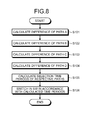
- FIG. 8 illustrates a flowchart of an exemplary process performed by the wireless apparatus 200 according to the second embodiment.
- the subtractor 172 first calculates a difference between a feedback signal and a transmission signal before distortion compensation in the path A (step S 101 ).
- the subtractor 172 then calculates a difference between a feedback signal and a transmission signal before distortion compensation in the path B (step S 102 ).
- the subtractor 172 then calculates a difference between a feedback signal and a transmission signal before distortion compensation in the path C (step S 103 ).
- the subtractor 172 then calculates a difference between a feedback signal and a transmission signal before distortion compensation in the path D (step S 104 ).
- the SW controller 180 calculates selection time periods of the respective paths based on the calculated differences of the respective paths (step S 105 ). For example, the SW controller 180 may calculate and allocate time periods for selecting signals of the respective paths in the switch 162 in proportion to the magnitudes of the calculated differences of the respective paths. Alternatively, the SW controller 180 may calculate time periods for selecting signals of the respective paths in the switch 162 based on the magnitudes of the calculated differences of the respective paths, but not in proportion to the magnitudes.
- the SW controller 180 executes selection (switching) of feedback signals of the respective paths in the switch 162 in accordance with the calculated selection time periods of the respective paths (step S 106 ).
- the wireless apparatus 300 of the third embodiment differs from that of the second embodiment in that adjacent channel leaking power or an ACPR of a feedback signal is used as an index of a magnitude of a distortion. Description of structural components and functions similar to those of the second embodiment will not be repeated.
- FIG. 9 illustrates a configuration of the wireless apparatus 300 according to the third embodiment.
- the wireless apparatus 300 includes a Fourier transform unit (FFT (Fast Fourier Transform)) 190 , an ACPR calculator 192 , an adjacent channel leaking power calculator 194 , and an SW controller 196 .
- FFT Fast Fourier Transform
- the Fourier transform unit 190 performs fast Fourier transform processing on a feedback signal that has been selected in the switch 162 and has thereafter undergone processing in the A/D converter 168 and the modulator 170 .
- the ACPR calculator 192 calculates a ratio of power of adjacent channels to power of a main channel for the signal. It is to be noted that, although an example of calculating the ACPR is illustrated in the present embodiment, an ACLR (Adjacent Channel Leakage Ratio) can be used instead of the ACPR.
- the adjacent channel leaking power calculator 194 calculates adjacent channel leaking power of the feedback signal that has been selected in the switch 162 and has thereafter undergone processing in the A/D converter 168 and the modulator 170 .
- the SW controller 196 controls the length of time during which each feedback signal is selected in a time-divisional manner in the switch 162 depending on the magnitude of a distortion of each of a plurality of transmission signals output from a plurality of paths A to D.
- the SW controller 196 controls the length of time during which each feedback signal is selected in a time-divisional manner in the switch 162 depending on the ratio of power of adjacent channels to power of a main channel for each feedback signal calculated in the ACPR calculator 192 . More specifically, the SW controller 196 compares the magnitudes of the ratios of power of adjacent channels to power of a main channel for the respective feedback signals calculated in the ACPR calculator 192 .
- the SW controller 196 then makes the length of time during which a feedback signal is selected in a time-divisional manner in the switch 162 longer for a feedback signal from a path having a larger ratio of power of adjacent channels to power of a main channel.
- the SW controller 196 provides a path having a larger power ratio with a larger number of times of updating of the distortion compensation coefficient stored in the distortion compensation coefficient storing unit 114 (LUT).
- the SW controller 196 controls the length of time during which each feedback signal is selected in a time-divisional manner in the switch 162 depending on the magnitude of the adjacent channel leaking power of each feedback signal calculated in the adjacent channel leaking power calculator 194 . More specifically, the SW controller 196 compares the adjacent channel leaking power values of the respective feedback signals calculated in the adjacent channel leaking power calculator 194 . The SW controller 196 then makes a time during which a feedback signal is selected in a time-divisional manner in the switch 162 longer for a feedback signal from a path having a larger adjacent channel leaking power value. In other words, the SW controller 196 provides a path having a larger adjacent channel leaking power value with a larger number of times of updating of the distortion compensation coefficient stored in the distortion compensation coefficient storing unit 114 (LUT).
- FIG. 10 illustrates a flowchart of an exemplary process performed by the wireless apparatus 300 according to the third embodiment.
- the Fourier transform unit 190 first performs fast Fourier transform on a feedback signal in the path A (step S 201 ).
- the ACPR calculator 192 calculates a ratio of power of adjacent channels to power of a main channel for the feedback signal in the path A (step S 202 ).
- the Fourier transform unit 190 performs fast Fourier transform on a feedback signal in the path B (step S 203 ).
- the ACPR calculator 192 calculates a ratio of power of adjacent channels to power of a main channel for the feedback signal in the path B (step S 204 ).
- the Fourier transform unit 190 performs fast Fourier transform on a feedback signal in the path C (step S 205 ).
- the ACPR calculator 192 calculates a ratio of power of adjacent channels to power of a main channel for the feedback signal in the path C (step S 206 ).
- the Fourier transform unit 190 performs fast Fourier transform on a feedback signal in the path D (step S 207 ).
- the ACPR calculator 192 calculates a ratio of power of adjacent channels to power of a main channel for the feedback signal in the path D (step S 208 ).
- the SW controller 196 calculates selection time periods of the respective paths based on the calculated power ratios of the respective paths (step S 209 ). For example, the SW controller 196 may calculate time periods for selecting the respective paths in the switch 162 in proportion to the magnitudes of the calculated power ratios of the respective paths. Alternatively, the SW controller 196 may calculate time periods for selecting the respective paths in the switch 162 in accordance with the magnitudes of the calculated power ratios of the respective paths but not in proportion to the magnitudes.
- the SW controller 196 executes selection (switching) of feedback signals of the respective paths in the switch 162 in accordance with the calculated selection time periods of the respective paths (step S 210 ).
- FIG. 11 illustrates a flowchart of another exemplary process performed by the wireless apparatus 300 according to the third embodiment.
- the Fourier transform unit 190 first performs fast Fourier transform on a feedback signal in the path A (step S 301 ).
- the adjacent channel leaking power calculator 194 calculates adjacent channel leaking power for the feedback signal in the path A (step S 302 ).
- the Fourier transform unit 190 performs fast Fourier transform on a feedback signal in the path B (step S 303 ).
- the adjacent channel leaking power calculator 194 calculates adjacent channel leaking power for the feedback signal in the path B (step S 304 ).
- the Fourier transform unit 190 performs fast Fourier transform on a feedback signal in the path C (step S 305 ).
- the adjacent channel leaking power calculator 194 calculates adjacent channel leaking power for the feedback signal in the path C (step S 306 ).
- the Fourier transform unit 190 performs fast Fourier transform on a feedback signal in the path D (step S 307 ).
- the adjacent channel leaking power calculator 194 calculates adjacent channel leaking power for the feedback signal in the path D (step S 308 ).
- the SW controller 196 calculates selection time periods of the respective paths based on the calculated adjacent channel leaking power values of the respective paths (step S 309 ). For example, the SW controller 196 may calculate time periods for selecting the respective paths in the switch 162 in proportion to the magnitudes of the calculated adjacent channel leaking power values of the respective paths. Alternatively, the SW controller 196 may calculate time periods for selecting signals of the respective paths in the switch 162 in accordance with the magnitudes of the calculated adjacent channel leaking power values of the respective paths, but not in proportion to the magnitudes.
- the SW controller 196 executes selection (switching) of feedback signals of the respective paths in the switch 162 in accordance with the calculated selection time periods of the respective paths (step S 310 ).
- the wireless apparatuses include a plurality of amplifiers, monitor magnitudes of distortions of signals output from the respective amplifiers, and control the switching time periods of feedback signals in accordance with the magnitudes.
- the wireless apparatus 200 controls the switch 162 so that update in the LUT may be performed for a longer time period for a path including an amplifier having a large distortion than for a path including an amplifier having a small distortion.
- sufficient distortion compensation is performed for the path experiencing a large distortion.
- update of the distortion compensation coefficient is not performed frequently for the signal of the path having a small distortion. Because the signal of such path experiences almost no distortion from the beginning, an influence on adjacent channels is restricted.
- time taken for distortion compensation of signals output from a plurality of amplifiers can be shortened.
- the process performed by the wireless apparatus may be stored, as a computer program, in a computer-readable storage medium such as floppy disk, CD-ROM (compact disc read only memory), DVD (digital versatile disc), magnet-optical disc and IC card.
- the program may be read from the computer-readable storage medium and executed by a computer.
Abstract
Description
hn(p)=hn−1(p)+μe(t)u*(t)
e(t)=x(t)−y(t)
y(t)=hn−1(p)x(t)f(p)
u*(t)=x(t)f(p)=hn−1(p)y*(t)
p=|x(t)|2
Claims (10)
Applications Claiming Priority (2)
| Application Number | Priority Date | Filing Date | Title |
|---|---|---|---|
| JP2012-083170 | 2012-03-30 | ||
| JP2012083170A JP5811929B2 (en) | 2012-03-30 | 2012-03-30 | Wireless device, distortion compensation method, and distortion compensation program |
Publications (2)
| Publication Number | Publication Date |
|---|---|
| US20130259154A1 US20130259154A1 (en) | 2013-10-03 |
| US8831136B2 true US8831136B2 (en) | 2014-09-09 |
Family
ID=49235018
Family Applications (1)
| Application Number | Title | Priority Date | Filing Date |
|---|---|---|---|
| US13/753,818 Expired - Fee Related US8831136B2 (en) | 2012-03-30 | 2013-01-30 | Wireless apparatus and distortion compensating method |
Country Status (2)
| Country | Link |
|---|---|
| US (1) | US8831136B2 (en) |
| JP (1) | JP5811929B2 (en) |
Cited By (12)
| Publication number | Priority date | Publication date | Assignee | Title |
|---|---|---|---|---|
| US20160269091A1 (en) * | 2015-03-10 | 2016-09-15 | Fujitsu Limited | Wireless communication device, control method of wireless communication device and phase shifter |
| US9876657B1 (en) * | 2017-03-06 | 2018-01-23 | Xilinx, Inc. | System and method for downlink processing in communication systems |
| US20180102796A1 (en) * | 2016-10-07 | 2018-04-12 | Rohde & Schwarz Gmbh & Co. Kg | Predistortion system and method |
| US20180316367A1 (en) * | 2015-11-27 | 2018-11-01 | Telefonaktiebolaget Lm Ericsson (Publ) | Linearization of active antenna array |
| US10469109B2 (en) * | 2017-09-19 | 2019-11-05 | Qualcomm Incorporated | Predistortion for transmitter with array |
| US10516452B1 (en) * | 2018-06-08 | 2019-12-24 | University Of South Florida | Using artificial signals to maximize capacity and secrecy of multiple-input multiple-output (MIMO) communication |
| US10644771B2 (en) * | 2018-06-08 | 2020-05-05 | University Of South Florida | Using artificial signals to maximize capacity and secrecy of multiple-input multiple-output (MIMO) communication |
| US20200244509A1 (en) * | 2019-01-28 | 2020-07-30 | Qualcomm Incorporated | In-phase and quadrature-phase estimation and correction using kernel analysis |
| US11115260B2 (en) * | 2019-04-23 | 2021-09-07 | Realtek Semiconductor Corporation | Signal compensation device |
| US20210391898A1 (en) * | 2020-02-03 | 2021-12-16 | Tencent Technology (Shenzhen) Company Limited | Sideband suppression method and apparatus, computer device, and storage medium |
| US11368348B2 (en) * | 2018-11-19 | 2022-06-21 | Huawei Technologies Co., Ltd. | Signal transmission method and apparatus |
| US11456760B1 (en) * | 2021-03-05 | 2022-09-27 | Motorola Solutions, Inc. | Linearizing narrowband carriers with low resolution predistorters |
Families Citing this family (3)
| Publication number | Priority date | Publication date | Assignee | Title |
|---|---|---|---|---|
| JP5637065B2 (en) * | 2011-05-13 | 2014-12-10 | 住友電気工業株式会社 | Amplifier circuit and wireless communication device |
| US10659124B2 (en) * | 2018-03-01 | 2020-05-19 | Fujitsu Limited | Multiantenna communication device and coefficient update method |
| US10476549B1 (en) * | 2018-05-04 | 2019-11-12 | Futurewei Technologies, Inc. | Transmitter linearity built-in-self-test |
Citations (14)
| Publication number | Priority date | Publication date | Assignee | Title |
|---|---|---|---|---|
| US5852630A (en) * | 1997-07-17 | 1998-12-22 | Globespan Semiconductor, Inc. | Method and apparatus for a RADSL transceiver warm start activation procedure with precoding |
| US5864710A (en) * | 1996-07-23 | 1999-01-26 | Compaq Computer Corporation | Controllerless modem |
| JPH11136302A (en) | 1997-10-29 | 1999-05-21 | Fujitsu Ltd | Distortion compensation circuit |
| US6246286B1 (en) * | 1999-10-26 | 2001-06-12 | Telefonaktiebolaget Lm Ericsson | Adaptive linearization of power amplifiers |
| JP2001189685A (en) | 1999-12-28 | 2001-07-10 | Fujitsu Ltd | Distortion compensator |
| JP2001345718A (en) | 2000-06-06 | 2001-12-14 | Fujitsu Ltd | Method of starting up communication apparatus provided with non-linear distortion compensator |
| US6697436B1 (en) * | 1999-07-13 | 2004-02-24 | Pmc-Sierra, Inc. | Transmission antenna array system with predistortion |
| US6920127B2 (en) * | 1999-08-31 | 2005-07-19 | Interdigital Technology Corporation | User equipment (UE) having an adaptive RF amplifier prelimiter |
| US6967436B2 (en) * | 2002-03-18 | 2005-11-22 | Byoung-Choo Park | Matrix-type triode organic electroluminescent display |
| JP2006074539A (en) | 2004-09-03 | 2006-03-16 | Fujitsu General Ltd | Method of controlling wireless radio provided with non-linear distortion compensating function, and wireless radio using same |
| US20060188038A1 (en) * | 2005-02-21 | 2006-08-24 | Fujitsu Limited | Distortion compensation apparatus |
| US7164738B2 (en) * | 1999-11-30 | 2007-01-16 | Fujitsu Limited | Signal canceling method and device |
| JP2009272762A (en) | 2008-05-01 | 2009-11-19 | Hitachi Kokusai Electric Inc | Amplifying device having distortion compensation function |
| US20130177105A1 (en) * | 2008-02-28 | 2013-07-11 | Broadcom Corporation | Method and system for estimating and compensating non-linear distortion in a transmitter using calibration |
Family Cites Families (2)
| Publication number | Priority date | Publication date | Assignee | Title |
|---|---|---|---|---|
| US20100087227A1 (en) * | 2008-10-02 | 2010-04-08 | Alvarion Ltd. | Wireless base station design |
| WO2013118367A1 (en) * | 2012-02-09 | 2013-08-15 | 日本電気株式会社 | Transmitter and transmission method |
-
2012
- 2012-03-30 JP JP2012083170A patent/JP5811929B2/en not_active Expired - Fee Related
-
2013
- 2013-01-30 US US13/753,818 patent/US8831136B2/en not_active Expired - Fee Related
Patent Citations (16)
| Publication number | Priority date | Publication date | Assignee | Title |
|---|---|---|---|---|
| US5864710A (en) * | 1996-07-23 | 1999-01-26 | Compaq Computer Corporation | Controllerless modem |
| US5852630A (en) * | 1997-07-17 | 1998-12-22 | Globespan Semiconductor, Inc. | Method and apparatus for a RADSL transceiver warm start activation procedure with precoding |
| JPH11136302A (en) | 1997-10-29 | 1999-05-21 | Fujitsu Ltd | Distortion compensation circuit |
| US6697436B1 (en) * | 1999-07-13 | 2004-02-24 | Pmc-Sierra, Inc. | Transmission antenna array system with predistortion |
| US6920127B2 (en) * | 1999-08-31 | 2005-07-19 | Interdigital Technology Corporation | User equipment (UE) having an adaptive RF amplifier prelimiter |
| US6246286B1 (en) * | 1999-10-26 | 2001-06-12 | Telefonaktiebolaget Lm Ericsson | Adaptive linearization of power amplifiers |
| US7164738B2 (en) * | 1999-11-30 | 2007-01-16 | Fujitsu Limited | Signal canceling method and device |
| JP2001189685A (en) | 1999-12-28 | 2001-07-10 | Fujitsu Ltd | Distortion compensator |
| US6836517B2 (en) | 1999-12-28 | 2004-12-28 | Fujitsu Limited | Distortion compensating apparatus |
| US6907085B2 (en) | 2000-06-06 | 2005-06-14 | Fujitsu Limited | Activation method of communications apparatus with a non-linear distortion compensation device |
| JP2001345718A (en) | 2000-06-06 | 2001-12-14 | Fujitsu Ltd | Method of starting up communication apparatus provided with non-linear distortion compensator |
| US6967436B2 (en) * | 2002-03-18 | 2005-11-22 | Byoung-Choo Park | Matrix-type triode organic electroluminescent display |
| JP2006074539A (en) | 2004-09-03 | 2006-03-16 | Fujitsu General Ltd | Method of controlling wireless radio provided with non-linear distortion compensating function, and wireless radio using same |
| US20060188038A1 (en) * | 2005-02-21 | 2006-08-24 | Fujitsu Limited | Distortion compensation apparatus |
| US20130177105A1 (en) * | 2008-02-28 | 2013-07-11 | Broadcom Corporation | Method and system for estimating and compensating non-linear distortion in a transmitter using calibration |
| JP2009272762A (en) | 2008-05-01 | 2009-11-19 | Hitachi Kokusai Electric Inc | Amplifying device having distortion compensation function |
Cited By (15)
| Publication number | Priority date | Publication date | Assignee | Title |
|---|---|---|---|---|
| US9602184B2 (en) * | 2015-03-10 | 2017-03-21 | Fujitsu Limited | Wireless communication device, control method of wireless communication device and phase shifter |
| US20160269091A1 (en) * | 2015-03-10 | 2016-09-15 | Fujitsu Limited | Wireless communication device, control method of wireless communication device and phase shifter |
| US10530399B2 (en) * | 2015-11-27 | 2020-01-07 | Telefonaktiebolaget Lm Ericsson (Publ) | Linearization of active antenna array |
| US20180316367A1 (en) * | 2015-11-27 | 2018-11-01 | Telefonaktiebolaget Lm Ericsson (Publ) | Linearization of active antenna array |
| US20180102796A1 (en) * | 2016-10-07 | 2018-04-12 | Rohde & Schwarz Gmbh & Co. Kg | Predistortion system and method |
| US9973219B2 (en) * | 2016-10-07 | 2018-05-15 | Rohde & Schwarz Gmbh & Co. Kg | Predistortion system and method |
| US9876657B1 (en) * | 2017-03-06 | 2018-01-23 | Xilinx, Inc. | System and method for downlink processing in communication systems |
| US10469109B2 (en) * | 2017-09-19 | 2019-11-05 | Qualcomm Incorporated | Predistortion for transmitter with array |
| US10516452B1 (en) * | 2018-06-08 | 2019-12-24 | University Of South Florida | Using artificial signals to maximize capacity and secrecy of multiple-input multiple-output (MIMO) communication |
| US10644771B2 (en) * | 2018-06-08 | 2020-05-05 | University Of South Florida | Using artificial signals to maximize capacity and secrecy of multiple-input multiple-output (MIMO) communication |
| US11368348B2 (en) * | 2018-11-19 | 2022-06-21 | Huawei Technologies Co., Ltd. | Signal transmission method and apparatus |
| US20200244509A1 (en) * | 2019-01-28 | 2020-07-30 | Qualcomm Incorporated | In-phase and quadrature-phase estimation and correction using kernel analysis |
| US11115260B2 (en) * | 2019-04-23 | 2021-09-07 | Realtek Semiconductor Corporation | Signal compensation device |
| US20210391898A1 (en) * | 2020-02-03 | 2021-12-16 | Tencent Technology (Shenzhen) Company Limited | Sideband suppression method and apparatus, computer device, and storage medium |
| US11456760B1 (en) * | 2021-03-05 | 2022-09-27 | Motorola Solutions, Inc. | Linearizing narrowband carriers with low resolution predistorters |
Also Published As
| Publication number | Publication date |
|---|---|
| JP5811929B2 (en) | 2015-11-11 |
| US20130259154A1 (en) | 2013-10-03 |
| JP2013214826A (en) | 2013-10-17 |
Similar Documents
| Publication | Publication Date | Title |
|---|---|---|
| US8831136B2 (en) | Wireless apparatus and distortion compensating method | |
| JP4786644B2 (en) | Distortion compensation device | |
| CN1601892B (en) | Distortion-compensated amplifier using predistortion technique | |
| US7486744B2 (en) | Distortion compensation apparatus | |
| JP4652091B2 (en) | Distortion compensation device | |
| JP4619827B2 (en) | Distortion compensation device | |
| JP5861521B2 (en) | Transmitting apparatus and lookup table update method | |
| JP2002232325A (en) | Predistortion distortion compensation device | |
| JP2003092518A (en) | Distortion compensator | |
| US20090227216A1 (en) | Apparatus for updating coefficient for distortion compensation and amplifier for compensating distortion | |
| JP5505002B2 (en) | Distortion compensation device, amplification device, transmission device, and distortion compensation method | |
| US9337783B2 (en) | Distortion compensation apparatus and distortion compensation method | |
| KR20110104869A (en) | Distortion compensating apparatus, amplifying apparatus, transmitting apparatus, and distortion compensating method | |
| JP2008294518A (en) | Transmission device | |
| JP2006270797A (en) | Device and method for distortion compensation | |
| US8798197B2 (en) | Distortion compensation amplifier device and distortion compensation method | |
| US9172333B2 (en) | Distortion compensation device and distortion compensation method | |
| US8897391B2 (en) | Distortion compensator and distortion compensation method | |
| JP5672728B2 (en) | Radio apparatus, distortion compensation apparatus, and distortion compensation method | |
| US20140003554A1 (en) | Distortion compensating device and distortion compensating method | |
| JP4939281B2 (en) | Amplifier | |
| KR100939882B1 (en) | Strain compensation device |
Legal Events
| Date | Code | Title | Description |
|---|---|---|---|
| AS | Assignment |
Owner name: FUJITSU LIMITED, JAPAN Free format text: ASSIGNMENT OF ASSIGNORS INTEREST;ASSIGNORS:ISHIKAWA, HIKARU;MATSUBARA, SATOSHI;SHAKO, HIDEHARU;REEL/FRAME:029740/0992 Effective date: 20121207 |
|
| STCF | Information on status: patent grant |
Free format text: PATENTED CASE |
|
| MAFP | Maintenance fee payment |
Free format text: PAYMENT OF MAINTENANCE FEE, 4TH YEAR, LARGE ENTITY (ORIGINAL EVENT CODE: M1551) Year of fee payment: 4 |
|
| FEPP | Fee payment procedure |
Free format text: MAINTENANCE FEE REMINDER MAILED (ORIGINAL EVENT CODE: REM.); ENTITY STATUS OF PATENT OWNER: LARGE ENTITY |
|
| LAPS | Lapse for failure to pay maintenance fees |
Free format text: PATENT EXPIRED FOR FAILURE TO PAY MAINTENANCE FEES (ORIGINAL EVENT CODE: EXP.); ENTITY STATUS OF PATENT OWNER: LARGE ENTITY |
|
| STCH | Information on status: patent discontinuation |
Free format text: PATENT EXPIRED DUE TO NONPAYMENT OF MAINTENANCE FEES UNDER 37 CFR 1.362 |
|
| FP | Lapsed due to failure to pay maintenance fee |
Effective date: 20220909 |