US8831742B2 - Systems and methods for identifying the circumferential positioning of electrodes of leads for electrical stimulation systems - Google Patents
Systems and methods for identifying the circumferential positioning of electrodes of leads for electrical stimulation systems Download PDFInfo
- Publication number
- US8831742B2 US8831742B2 US13/750,725 US201313750725A US8831742B2 US 8831742 B2 US8831742 B2 US 8831742B2 US 201313750725 A US201313750725 A US 201313750725A US 8831742 B2 US8831742 B2 US 8831742B2
- Authority
- US
- United States
- Prior art keywords
- lead
- electrodes
- lead body
- disposed
- marker
- Prior art date
- Legal status (The legal status is an assumption and is not a legal conclusion. Google has not performed a legal analysis and makes no representation as to the accuracy of the status listed.)
- Active
Links
Images


Classifications
-
- A—HUMAN NECESSITIES
- A61—MEDICAL OR VETERINARY SCIENCE; HYGIENE
- A61N—ELECTROTHERAPY; MAGNETOTHERAPY; RADIATION THERAPY; ULTRASOUND THERAPY
- A61N1/00—Electrotherapy; Circuits therefor
- A61N1/02—Details
- A61N1/04—Electrodes
- A61N1/05—Electrodes for implantation or insertion into the body, e.g. heart electrode
- A61N1/0526—Head electrodes
- A61N1/0529—Electrodes for brain stimulation
- A61N1/0534—Electrodes for deep brain stimulation
-
- A—HUMAN NECESSITIES
- A61—MEDICAL OR VETERINARY SCIENCE; HYGIENE
- A61N—ELECTROTHERAPY; MAGNETOTHERAPY; RADIATION THERAPY; ULTRASOUND THERAPY
- A61N1/00—Electrotherapy; Circuits therefor
- A61N1/18—Applying electric currents by contact electrodes
- A61N1/32—Applying electric currents by contact electrodes alternating or intermittent currents
- A61N1/36—Applying electric currents by contact electrodes alternating or intermittent currents for stimulation
- A61N1/3605—Implantable neurostimulators for stimulating central or peripheral nerve system
- A61N1/3606—Implantable neurostimulators for stimulating central or peripheral nerve system adapted for a particular treatment
-
- H—ELECTRICITY
- H01—ELECTRIC ELEMENTS
- H01R—ELECTRICALLY-CONDUCTIVE CONNECTIONS; STRUCTURAL ASSOCIATIONS OF A PLURALITY OF MUTUALLY-INSULATED ELECTRICAL CONNECTING ELEMENTS; COUPLING DEVICES; CURRENT COLLECTORS
- H01R43/00—Apparatus or processes specially adapted for manufacturing, assembling, maintaining, or repairing of line connectors or current collectors or for joining electric conductors
- H01R43/16—Apparatus or processes specially adapted for manufacturing, assembling, maintaining, or repairing of line connectors or current collectors or for joining electric conductors for manufacturing contact members, e.g. by punching and by bending
-
- Y—GENERAL TAGGING OF NEW TECHNOLOGICAL DEVELOPMENTS; GENERAL TAGGING OF CROSS-SECTIONAL TECHNOLOGIES SPANNING OVER SEVERAL SECTIONS OF THE IPC; TECHNICAL SUBJECTS COVERED BY FORMER USPC CROSS-REFERENCE ART COLLECTIONS [XRACs] AND DIGESTS
- Y10—TECHNICAL SUBJECTS COVERED BY FORMER USPC
- Y10T—TECHNICAL SUBJECTS COVERED BY FORMER US CLASSIFICATION
- Y10T29/00—Metal working
- Y10T29/49—Method of mechanical manufacture
- Y10T29/49002—Electrical device making
- Y10T29/49117—Conductor or circuit manufacturing
- Y10T29/49204—Contact or terminal manufacturing
- Y10T29/49208—Contact or terminal manufacturing by assembling plural parts
Definitions
- the invention is directed to the area of electrical stimulation systems and methods of making and using the systems.
- the present invention is also directed to electrical stimulation leads having electrodes and markers identifying the circumferential positioning of one or more of the electrodes, as well as methods of making and using the leads, electrodes, markers, and electrical stimulation systems.
- Deep brain stimulation can be useful for treating a variety of conditions. Deep brain stimulation can be useful for treating, for example, Parkinson's disease, dystonia, essential tremor, chronic pain, Huntington's disease, levodopa-induced dyskinesias and rigidity, bradykinesia, epilepsy and seizures, eating disorders, and mood disorders.
- a lead with a stimulating electrode at or near a tip of the lead provides the stimulation to target neurons in the brain.
- Magnetic resonance imaging (“MRI”) or computerized tomography (“CT”) scans can provide a starting point for determining where the stimulating electrode should be positioned to provide the desired stimulus to the target neurons.
- MRI Magnetic resonance imaging
- CT computerized tomography
- electrical stimulus current can be delivered through selected electrodes on the lead to stimulate target neurons in the brain.
- the electrodes are formed into rings disposed on a distal portion of the lead.
- the stimulus current projects from the ring electrodes equally in every direction. Because of the ring shape of these electrodes, the stimulus current cannot be directed to one or more specific positions around the ring electrode (e.g., on one or more sides, or points, around the lead). Consequently, undirected stimulation may result in unwanted stimulation of neighboring neural tissue, potentially resulting in undesired side effects.
- a lead assembly for an electrical stimulation system includes a lead body having a distal end, a proximal end, a longitudinal length, and a circumference.
- a plurality of electrodes are disposed along the distal end of the lead body.
- the plurality of electrodes include a plurality of segmented electrodes. Each of the plurality of segmented electrodes extends partially around the circumference of the lead body.
- a plurality of terminals are disposed along the proximal end of the lead body.
- a plurality of conductors electrically couple at least one of the plurality of electrodes to at least one of the plurality of lead terminals. At least one distal marker is disposed along the distal end of the lead body.
- the distal marker identifies the circumferential position of at least one of the plurality of segmented electrodes along the lead body.
- the distal marker is aligned with the at least one of the plurality of segmented electrodes along the longitudinal length of the lead body.
- At least one proximal marker is disposed along the proximal end of the lead body.
- the proximal marker is aligned with the distal marker along the longitudinal length of the lead body.
- the at least one distal marker and the at least one proximal marker are discontinuous with one another along the lead body.
- a method for marking a lead of an implantable electrical stimulation system includes forming an elongated multi-lumen conductor guide defining a central lumen and a plurality of conductor lumens arranged around the central lumen. At least a portion of the multi-lumen conductor guide is twisted to form at least one helical section where the plurality of conductor lumens each forms a helical pathway around the central lumen. At least one conductor is inserted into one of the plurality of conductor lumens. A plurality of segmented electrodes are formed along one end of the multi-lumen conductor guide. The plurality of segmented electrodes are electrically coupled to the at least one conductor. An ablation is formed along a longitudinal length of the twisted multi-lumen conductor guide. The ablation is aligned along the longitudinal length of the multi-lumen conductor guide with a one of the plurality of segmented electrodes.
- FIG. 1 is a schematic side view of one embodiment of a brain stimulation system that includes a lead with a lead body, a lead extension, and a control unit, according to the invention
- FIG. 2A is a transverse cross-sectional view of one embodiment of a portion of the lead body of FIG. 1 , the lead body including a multi-lumen conductor guide that defines a central lumen and a plurality of conductor lumens arranged around the central lumen, according to the invention;
- FIG. 2B is a transverse cross-sectional view of one embodiment of conductors disposed in each of a plurality of conductor lumens of the multi-lumen conductor guide of FIG. 2A , according to the invention;
- FIG. 3A is a schematic side view of one embodiment of a helical section of the multi-lumen conductor guide of FIG. 2A , the helical section defining a plurality of conductor lumens each defining a clockwise helical pathway around at least a portion of a central lumen, according to the invention;
- FIG. 3B is a schematic side view of another embodiment of a helical section of the multi-lumen conductor guide of FIG. 2A , the helical section defining a plurality of conductor lumens each defining a counter-clockwise helical pathway around at least a portion of a central lumen, according to the invention;
- FIG. 4 is a schematic diagram of one embodiment of radial current steering along various electrodes disposed along the longitudinal length of the lead body of FIG. 1 , according to the invention
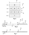
- FIG. 5 is a schematic side view of one embodiment of the electrodes of FIG. 1 arranged into a flat configuration, according to the invention
- FIG. 6 is a schematic side view of one embodiment of a lead with segmented electrodes disposed at a distal end of the lead, terminals disposed at a proximal end of the lead, a distal marker rotationally aligned with at least one of the segmented electrodes, and a proximal marker rotationally aligned with the distal marker, according to the invention;
- FIG. 7 is a schematic side view of another embodiment of a distal marker disposed at a distal end of the lead of FIG. 6 and a proximal marker disposed at a proximal end of the lead of FIG. 6 , where the distal and proximal markers are inset from an outer surface of the lead, according to the invention;
- FIG. 8A is a schematic side view of another embodiment of a distal marker disposed at a distal end of the lead of FIG. 6 and a proximal marker disposed at a proximal end of the lead of FIG. 6 , where the distal and proximal markers are formed on or in spacers, according to the invention;
- FIG. 8B is a schematic side view of another embodiment of a distal marker disposed at a distal end of the lead of FIG. 6 and a proximal marker disposed at a proximal end of the lead of FIG. 6 , where the distal and proximal markers are formed on or in spacers, according to the invention;
- FIG. 9 is a schematic side view of another embodiment of a distal marker disposed at a distal end of the lead of FIG. 6 and a proximal marker disposed at a proximal end of the lead of FIG. 6 , where the distal marker is formed on or in a ring electrode, according to the invention;
- FIG. 10 is a schematic side view of an embodiment of a distal marker disposed at a distal end of the lead of FIG. 6 and a proximal marker disposed at a proximal end of the lead of FIG. 6 , where the proximal marker is formed on or in a terminal, according to the invention;
- FIG. 11 is a schematic side view of another embodiment of a distal marker disposed at a distal end of the lead of FIG. 6 and a proximal marker disposed at a proximal end of the lead of FIG. 6 , where the proximal marker is formed on or in a retention sleeve, according to the invention.
- FIG. 12 is a schematic side view of another embodiment of a marker formed as an ablation extending along an entire length of the lead of FIG. 6 , according to the invention.
- the invention is directed to the area of electrical stimulation systems and methods of making and using the systems.
- the present invention is also directed to electrical stimulation leads having electrodes and markers identifying the circumferential positioning of one or more of the electrodes, as well as methods of making and using the leads, electrodes, markers, and electrical stimulation systems.
- a lead for deep brain stimulation may include stimulation electrodes, recording electrodes, or a combination of both.
- a practitioner may determine the position of the target neurons using the recording electrode(s) and then position the stimulation electrode(s) accordingly without removal of a recording lead and insertion of a stimulation lead.
- the same electrodes can be used for both recording and stimulation.
- separate leads can be used; one with recording electrodes which identify target neurons, and a second lead with stimulation electrodes that replaces the first after target neuron identification.
- a lead may include recording electrodes spaced around the circumference of the lead to more precisely determine the position of the target neurons.
- the lead is rotatable so that the stimulation electrodes can be aligned with the target neurons after the neurons have been located using the recording electrodes.
- Deep brain stimulation devices and leads are described in the art. See, for instance, U.S. Pat. No. 7,809,446 (“Devices and Methods For Brain Stimulation”), U.S. Patent Application Publication No. 2010/0076535 A1 (“Leads With Non-Circular-Shaped Distal Ends For Brain Stimulation Systems and Methods of Making and Using”), U.S. Patent Application Publication 2007/0150036 A1 (“Stimulator Leads and Methods For Lead Fabrication”), U.S. patent application Ser. No. 12/177,823 (“Lead With Transition and Methods of Manufacture and Use”), U.S. Patent Application Publication No.
- FIG. 1 illustrates one embodiment of an electrical stimulation system 100 for brain stimulation.
- the electrical stimulation system 100 includes a lead 110 having a lead body 115 , a plurality of electrodes 125 disposed at least partially about a circumference of the lead body 115 , a plurality of terminals 135 , a lead extension 130 for connection of the electrodes 125 to a control unit 160 , and a stylet 140 for assisting in insertion and positioning of the lead 110 in the patient's brain. It may be advantageous to include the lead extensions 130 to prevent having to remove or replace the lead 110 if the proximal end of the lead 110 fails due to fatigue (e.g., from flexing of the patient's neck, or the like).
- the stylet 140 can be made of a rigid material. Examples of suitable materials include tungsten, stainless steel, or plastic.
- the stylet 140 may have a handle 150 to assist insertion into the lead 110 , as well as rotation of the stylet 140 and lead 110 .
- the lead extension 130 includes a connector 170 that fits over a proximal end of the lead 110 , preferably after removal of the stylet 140 .
- the control unit 160 is typically an implantable pulse generator that can be implanted into a patient's body, for example, below the patient's clavicle area.
- the pulse generator can have eight stimulation channels which may be independently programmable to control the magnitude of the current stimulus from each channel. In some cases, the pulse generator may have more than eight stimulation channels (e.g., 16-, 32-, or more stimulation channels).
- the control unit 160 may have one, two, three, four, or more connector ports, for receiving the plurality of terminals 135 at the proximal end of the lead 110 .
- access to the desired stimulation location in the brain can be accomplished by drilling a hole in the patient's skull or cranium with a cranial drill (commonly referred to as a “burr” or “bur”), and coagulating and incising the dura mater, or brain covering.
- the lead 110 can be inserted into the cranium and brain tissue with the assistance of the stylet 140 .
- the lead 110 can be guided to the target stimulation location within the brain using, for example, a stereotactic frame and a microdrive motor system.
- the microdrive motor system can be fully or partially automatic.
- the microdrive motor system may be configured to perform one or more the following actions (alone or in combination): insert the lead 110 , retract the lead 110 , or rotate the lead 110 .
- measurement devices coupled to the muscles or other tissues stimulated by the target neurons, or a unit responsive to the patient or clinician can be coupled to the control unit or microdrive motor system.
- the measurement device, user, or clinician can indicate a response by the target muscles or other tissues to the stimulation or recording electrode(s) to further identify the target neurons and facilitate positioning of the stimulation electrode(s).
- a measurement device can be used to observe the muscle and indicate changes in tremor frequency or amplitude in response to stimulation of neurons.
- the patient or clinician may observe the muscle and provide feedback.
- the lead 110 for deep brain stimulation can include stimulation electrodes, recording electrodes, or both.
- the lead 110 has a cross-sectional diameter of no more than 1.5 mm and may be in the range of no less than 0.5 mm and no greater than 1.5 mm.
- the lead 110 is rotatable so that the stimulation electrodes 125 can be aligned with the target neurons after the neurons have been located using the recording electrodes.
- the stimulation electrodes 125 may be disposed on the circumference of the lead 110 to stimulate the target neurons.
- the stimulation electrodes 125 may be ring-shaped so that current projects from each electrode equally in every direction at any given length along the axis of the lead. To achieve current steering, segmented electrodes can be utilized additionally or alternatively. Though the following description discusses stimulation electrodes, it will be understood that all configurations of the stimulation electrodes discussed may be utilized in arranging recording electrodes as well.
- the stimulation electrodes 125 may be made using a metal, alloy, conductive oxide, or any other suitable conductive material. Examples of suitable materials include, but are not limited to, platinum, platinum iridium alloy, palladium, palladium-rhodium alloy, or titanium. Preferably, the stimulation electrodes 125 are made of a material that is biocompatible and does not substantially corrode under expected operating conditions in the operating environment for the expected duration of use.
- any of the electrodes can be used as an anode or cathode and carry anodic or cathodic current.
- an electrode might be an anode for a first period of time and a cathode for a second, non-overlapping period of time.
- the identity of a particular electrode or electrodes as an anode or cathode might be fixed.
- the lead extension 130 typically couples the electrodes 125 to the control unit 160 (which typically houses a pulse generator that supplies electrical signals to the electrodes 125 ).
- Connectors of conventional lead extensions are typically disposed within patient tissue such that the connectors are disposed over the patient's skull and beneath or within the patient's scalp above one of the patient's ear.
- the lead body 115 may include strain relief to modulate deflection of one or more portions of the lead in response to bending of one or more portions of the lead.
- Examples of lead bodies with strain relief are found in, for example, U.S. Patent Application Ser. No. 61/494,247 and U.S. Patent Application Ser. No. 61/554,861, each of which is incorporated herein by reference in its entirety. Strain relief may be provided in any suitable manner.
- the lead includes a lead body with one or more elongated multi-lumen conductor guides.
- the one or more multi-lumen conductor guides may include conductor lumens with one or more helical sections that provide strain relief.
- the lead body 115 includes an elongated multi-lumen conductor guide having multiple conductor lumens arranged about a central lumen.
- the conductor lumens are arranged about the central lumen such that there are no other lumens extending along the multi-lumen conductor guide between the central lumen and each of the multiple conductor lumens.
- the conductor lumens include at least one helical section forming an enclosed pathway around at least a portion of the central lumen.
- the conductor lumens are each configured and arranged to receive a single conductor. In other embodiments, at least one of the conductor lumens is configured and arranged to receive multiple conductors.
- FIG. 2A is a transverse cross-sectional view of one embodiment of a portion of the lead body 115 .
- the lead body 115 includes an elongated multi-lumen conductor guide 202 defining a central lumen 204 and a plurality of conductor lumens, such as conductor lumen 206 , disposed around the central lumen 204 .
- the central lumen 204 may be configured and arranged to receive a stylet, such as the stylet ( 140 in FIG. 1 ).
- the stylet 140 can be used for assisting in insertion and positioning of the lead in the patient's brain.
- FIG. 2B is a transverse cross-sectional view of one embodiment of conductors, such as conductor 208 , disposed in conductor lumens 206 .
- insulation 210 is disposed around the conductors 208 to prevent short-circuiting of the conductors 208 .
- the multi-lumen conductor guide 202 may extend an entire longitudinal length of the lead body 115 from the electrodes 125 to the terminals 135 .
- the conductor lumens 206 can have any suitable cross-sectional shape (e.g., round, oval, rectangular, triangular, or the like).
- FIGS. 3A and 3B are schematic side views of two embodiments of a helical section 302 of the multi-lumen conductor guide 202 .
- the helical section 302 can extend an entire length of the multi-lumen conductor guide 202 , or extend along one or more portions thereof, where each helical section 302 is only part of the longitudinal length of the multi-lumen conductor guide 202 .
- the conductor lumens 206 are twisted such that the individual conductor lumens 206 form helical pathways around the central lumen 204 .
- the conductor lumens 206 can extend in either clockwise or counter-clockwise directions.
- the conductor lumens 206 are shown extending in a clockwise direction around to the central lumen 204 (e.g., the conductor lumens 206 wrap around the central lumen 204 in a clockwise direction when the multi-lumen conductor guide 202 is viewed from the distal end).
- the conductor lumens 206 are shown extending in a counter-clockwise direction around to the central lumen 204 (e.g., the conductor lumens 206 wrap around the central lumen 204 in a counter-clockwise direction when the multi-lumen conductor guide 202 is viewed from the distal end).
- the conductor lumens 206 of the helical section 302 can have any suitable pitch.
- the pitch can be either constant or variable.
- the pitch may be at least 0.04 turns (i.e., 0.04 revolutions around a circumference of the central lumen 204 ) per cm.
- the pitch may be no less than 0.1 turns per cm.
- the pitch may be at least 0.2 turns per cm.
- the pitch may be at least 0.25 turns per cm.
- the pitch may be at least 0.8 turns per cm.
- the pitch may be at least 0.04 turns per cm and no greater than 0.8 turns per cm. In some cases, the pitch may be at least 0.1 turns per cm and no greater than 0.6 turns per cm. In some cases, the pitch may be at least 0.1 turns per cm and no greater than 0.4 turns per cm. In some cases, the pitch may be at least 0.2 turns per cm and no greater than 0.4 turns per cm. In some cases, the pitch may be approximately 0.3 turns per cm.
- each conductor lumen 206 of the helical section 302 forms at least 2, 3, 4, or 5 turns. In some cases, for a 40 cm section of the multi-lumen conductor guide 202 , each conductor lumen 206 of the helical section 302 forms no more than 25 turns.
- each conductor lumen 206 of the helical section 302 forms at least 2 turns and no more than 15 turns. In some cases, for a 40 cm section of the multi-lumen conductor guide 202 , each conductor lumen 206 of the helical section 302 forms no less than 3 turns and no more than 15 turns. In some cases, for a 40 cm section of the multi-lumen conductor guide 202 , each conductor lumen 206 of the helical section 302 forms at least 4 turns and no more than 15 turns. In some cases, for a 40 cm section of the multi-lumen conductor guide 202 , each conductor lumen 206 of the helical section 302 forms at least 5 turns and no more than 15 turns.
- the conductor lumens 206 of the helical section 302 can be configured into any suitable arrangement. As shown in FIG. 2A and FIG. 2B , the helical section 302 may include a single layer of conductor lumens 206 disposed over the central lumen 204 . Alternately, the helical section 302 may include two or more layers of conductor lumens 206 disposed over the central lumen 204 . As shown in FIG. 2A and FIG. 2B , the conductor lumens 206 may be disposed over a single central lumen 204 . Alternately, the conductor lumens 206 may be disposed over multiple central lumens 204 .
- the helical section 302 extends along an entire length of the lead body 115 between, but excluding, the sections containing the electrodes ( 125 in FIG. 1 ) and the terminals ( 135 in FIG. 1 ). In other cases, the helical section 302 extends along one or more discrete sections of the lead body 115 . When the helical section 302 extends along one or more discrete sections of the lead body 115 , the discrete helical section 302 can be any suitable length. In some cases, the discrete helical section 302 is at least 1 cm, 2 cm, 3 cm, 4 cm, 5 cm, 6 cm, 7 cm, 8 cm, 9 cm, 10 cm, 15 cm, 20 cm, 25 cm, 30 cm, or longer.
- the plurality of conductor lumens 206 are encapsulated by the multi-lumen conductor guide 202 such that the conductor lumens 206 do not extend to an outer surface 222 of the multi-lumen conductor guide 202 . In which case, when the conductors 208 are disposed in the conductor lumens 206 , the conductors 208 are not exposed along the outer surface 222 of the multi-lumen conductor guide 202 .
- the central lumen 204 and the plurality of conductor lumens 206 can be arranged in any suitable manner.
- the conductor lumens 206 are disposed in the multi-lumen conductor guide 202 such that the conductor lumens 206 are peripheral to the central lumen 204 .
- the lead body 115 may include one or more outer coatings of material 224 disposed over the outer surface 222 of multi-lumen conductor guide 202 .
- the one or more outer coatings 224 provide the lead body 115 with an isodiametric outer surface 226 . It will be understood that the lead body 115 may be isodiametric either with or without application of one or more coatings 224 .
- At least one of the conductor lumens 206 is configured and arranged to concurrently receive two or more conductors 208 . In some embodiments, at least one of the conductor lumens 206 can be configured and arranged to receive a different number of conductors than at least one other of the conductor lumens 206 . When the conductor lumens 206 are configured and arranged to receive a plurality of conductors, the conductor lumens 206 can be arranged in any suitable configuration.
- the discrete helical section 302 can be disposed at any suitable location along the length of the lead body 115 .
- the discrete helical section 300 may abut the electrodes ( 125 in FIG. 1 ), the terminals ( 135 in FIG. 1 ), or both.
- the discrete helical section 302 can be disposed somewhere along the length of the lead body 115 between the electrodes ( 125 in FIG. 1 ) and the terminals ( 135 in FIG. 1 ).
- the discrete helical section 302 is disposed somewhere along the length of the lead body 115 between the electrodes ( 125 in FIG.
- the remaining portions of the conductor lumens 206 can be arranged into one or more other configurations, such as a substantially-straight configuration (e.g., the conductor lumens 206 extend less than one revolution about a circumference of the central lumen 204 along a 20 cm length of the multi-lumen conductor guide 202 ).
- the multi-lumen conductor guide 202 can be formed as a single-piece component or as a multi-piece component.
- the multi-lumen conductor guide 202 can be formed from any suitable material(s).
- the multi-lumen conductor guide 202 can be formed from one or more thermoset polymers (e.g., silicone, or the like), thermoplastic polymers (e.g., polyurethane, or the like), or the like or combinations thereof.
- the multi-lumen conductor guide 202 can be formed in any suitable manner.
- the multi-lumen conductor guide 202 can be extruded.
- the multi-lumen conductor guide 202 can be twisted as the multi-lumen conductor guide 202 is being extruded, or after extrusion.
- the helical section(s) 3002 of the multi-lumen conductor guide 202 can be formed in any suitable manner.
- the multi-lumen conductor guide 202 (or one or more portions thereof) is formed in a substantially-straight conductor-lumen configuration and then twisted, as desired, to form the one or more helical sections 302 .
- the twisted multi-lumen conductor guide 202 may be heated to set the helical section(s).
- the multi-lumen conductor guide 202 may be heated prior to twisting.
- the multi-lumen conductor guide 202 may be heated while being twisted.
- the heating can be performed using at least one of: one or more transverse heating elements which heat one or more particular portions of the multi-lumen conductor guide 202 at a time, or an elongated heating element that heats the entire multi-lumen conductor guide 202 at once.
- the lead body 115 can be heated from the inside out, for example, by using one or more heating elements disposed in the central lumen 204 .
- the electrodes 125 are coupled to one end of the multi-lumen conductor guide 202 and the terminals 135 are coupled to the opposing end of the multi-lumen conductor guide 202 .
- outer portions of the multi-lumen conductor guide 202 are ablated at the ends to expose the conductor lumens 206 .
- the electrodes 125 may be disposed over the ablated portion at one end of the multi-lumen conductor guide 202
- the terminals 135 may be disposed over the ablated portion at the opposing end of the multi-lumen conductor guide 202 and be electrically coupled to conductors 208 extending within the exposed conductor lumens 206 .
- spacers are used to separate adjacent electrodes 125 (and adjacent terminals 135 ) from one another. In at least some embodiments, the spacers are isodiametric with the electrodes 125 (and terminals 135 ). In at least some embodiments, the lead body 115 , the spacers, the electrodes 125 , and the terminals 135 are isodiametric with one another.
- a target stimulation region a specific region of patient tissue disposed around the circumference of the lead without undesirably stimulating other patient tissue disposed about the circumference of the lead.
- the targeted stimulation region can be stimulated by rotating the lead until the directed stimulation energy propagating from one or more of the segmented electrodes is directed to the target stimulation region.
- FIG. 4 is a schematic diagram to illustrate radial current steering along electrodes disposed along the longitudinal length of the lead body 115 . While conventional lead configurations with ring electrodes are only able to steer current along the length of the lead (the z-axis), the segmented electrode configuration is capable of steering current in the x-axis, y-axis, as well as the z-axis. Thus, the centroid of stimulation may be steered in any direction in the three-dimensional space surrounding the lead body 115 .
- the radial distance, r, and the angle ⁇ around the circumference of the lead body 115 may be dictated by the percentage of anodic current (recognizing that stimulation predominantly occurs near the cathode, although strong anodes may cause stimulation as well) introduced to each electrode.
- the configuration of anodes and cathodes along the segmented electrodes enables the centroid of stimulation to be shifted to a variety of different locations along the lead body 115 .
- the stimulation electrodes 125 may be disposed on the lead 100 in any suitable configuration.
- FIG. 5 illustrates one embodiment of the electrodes 125 unrolled from a cylindrical shape (see e.g., FIG. 1 ) so that the electrodes 125 are laid out flat, for clarity of illustration of the configuration of the electrodes.
- FIG. 5 is a two-dimensional version of the three-dimensional electrode configuration of FIG. 1 .
- the electrodes 125 are shown flattened such that the length indicated by arrow 504 is equal to the circumference of the lead body 115 (see e.g., FIG. 1 ).
- the electrodes 125 of FIG. 5 include two ring electrodes 506 a and 506 b flanking a plurality of segmented electrodes 508 , such as segmented electrodes 508 a and 508 b arranged into two sets, or levels 510 and 512 .
- the electrodes 125 may include any number of ring electrodes, or even a single ring electrode.
- the electrodes 125 may include one ring electrode, two ring electrodes, three ring electrodes or four ring electrodes.
- the electrodes 502 include five, six, seven or eight ring electrodes.
- the ring electrodes 506 a , 506 b are substantially cylindrical and wrap around an entire circumference of the lead body 115 .
- the outer diameter of the ring electrodes 506 a , 506 b is substantially equal to the outer diameter of the lead body.
- the width of ring electrodes 506 a , 506 b may vary according to the desired treatment and the location of the target neurons. In some embodiments the width of the ring electrode 506 a is less than or equal to the diameter of the ring electrode 506 b . In other embodiments, the width of the ring electrode 506 a is greater than the diameter of the ring electrode 506 b.
- the electrodes 125 also include the segmented electrodes 508 .
- the electrodes 125 may include any number of segmented electrodes 508 collectively wrapped around the circumference of the lead body 115 .
- the segmented electrodes 508 are grouped into sets of segmented electrodes, such as sets 510 and 512 , where each set is configured for disposing around the circumference of the lead body 115 at or near a particular longitudinal position.
- the electrodes 125 may include any number of sets of segmented electrodes 508 .
- the electrodes 125 include one, two, three, four, five, six, seven, eight, or more sets of segmented electrodes 508 .
- each set of segmented electrodes contains the same number of segmented electrodes 508 .
- each set of segmented electrodes contains three segmented electrodes 508 .
- each set of segmented electrodes contains two, four, five, six, seven or eight segmented electrodes 508 .
- the segmented electrodes 508 may vary in size and shape. In some embodiments, the segmented electrodes 508 are all of the same size, shape, diameter, width, area or any combination thereof.
- any combination of ring electrodes 506 a , 506 b and segmented electrodes 508 may be disposed on the lead body 115 .
- the lead body 115 includes the ring electrode 506 a , two sets of segmented electrodes; each set formed of three segmented electrodes 508 , and the ring electrode 506 b .
- This configuration may simply be referred to as a 1-3-3-1 configuration. It may be useful to refer to the electrodes 125 with this shorthand notation.
- Other eight-electrode configurations include, for example, a 2-2-2-2 configuration, where four sets of segmented electrodes 508 are disposed on the lead, and a 4-4 configuration, where two sets of segmented electrodes, each having four segmented electrodes 508 , are disposed on the lead.
- the lead upon which the electrodes are disposed includes 16 electrodes. Possible configurations for a 16-electrode lead include, but are not limited to 4-4-4-4; 8-8; 3-3-3-3-3-1 (and all rearrangements of this configuration); and 2-2-2-2-2-2-2-2-2-2.
- each set of segmented electrodes 508 may be disposed around the circumference of the lead body 115 to form a substantially or approximately cylindrical shape around the lead body 115 .
- the spacing of the segmented electrodes 508 around the circumference of the lead body 115 may vary.
- equal spaces, gaps, or cutouts are disposed between each segmented electrode 508 disposed around the circumference of the lead body 115 (i.e., each segmented electrode 508 within a given set).
- the spaces, gaps, or cutouts between segmented electrodes 508 may differ in size or shape.
- the spaces, gaps, or cutouts between segmented electrodes 508 may be uniform for a particular set of segmented electrodes 508 or for all sets of segmented electrodes 508 .
- the segmented electrodes 508 When the segmented electrodes 508 are disposed on the lead body 115 , the segmented electrodes 508 may be positioned in irregular or regular intervals around the circumference of the lead body 115 such that each of the different segmented electrodes 508 extends around a different portion of the circumference. When the segmented electrodes 508 are disposed on the lead body 115 , for example in a 1-3-3-1 configuration, each of the segmented electrodes 508 extends partially around the circumference of the lead body 115 such that the segmented electrodes collectively extend no more than 98%, 96%, 94%, 92%, 90%, 80%, 70%, 60%, 50%, 40%, 30%, or 20% around the circumference of the lead body 115 .
- the centroid of stimulation can be shifted within each set 510 , 512 along the length of the lead body 115 .
- the use of multiple sets of segmented electrodes at different levels along the length of the lead allows for three-dimensional current steering.
- the sets of segmented electrodes are shifted collectively (i.e., the centroid of simulation is similar at each level along the length of the lead body 115 ).
- each set of segmented electrodes is controlled independently. It will be understood that different stimulation profiles may be produced by varying the number of segmented electrodes within each set 510 .
- each set of segmented electrodes includes only two segmented electrodes, uniformly distributed gaps (inability to stimulate selectively) may be formed in the stimulation profile.
- at least three segmented electrodes 130 are utilized to allow for true 360° selectivity.
- measurement devices coupled to the muscles or other tissues stimulated by the target neurons or a unit responsive to the patient or clinician can be coupled to the control unit or microdrive motor system.
- the measurement device, user, or clinician can indicate a response by the target muscles or other tissues to the stimulation or recording electrodes to further identify the target neurons and facilitate positioning of the stimulation electrodes.
- a measurement device can be used to observe the muscle and indicate changes in tremor frequency or amplitude in response to stimulation of neurons.
- the patient or clinician may observe the muscle and provide feedback.
- the target stimulation region may be located on one side of a plane extending through the longitudinal length of the lead. In other cases, the target stimulation region may be located at a plane that is offset at some angle from the longitudinal length of the lead.
- each of the electrodes 125 is coupled to a different terminal of the plurality of terminals 135 .
- the ring electrode 506 a which is numbered “1”
- the ring electrode 506 b which is numbered “8”
- each of the segmented electrodes 508 may be electrically coupled to a different terminal of the plurality of terminals 135 .
- the terminals 135 are also numbered to correspond to particular electrodes 125 .
- the terminals are numbered 1-8 such that the proximal-most terminal of the plurality of terminals is numbered “1,” and the next most proximal terminal is numbered “2,” and so on.
- the electrode “1” electrically couples with the terminal “1,” the electrode “2” electrically couples with the terminal “2,” and so on.
- the electrodes 125 are arranged such that when the electrodes 125 are disposed on the lead body (see e.g., FIG. 1 ), some of the segmented electrodes 508 align with one another along a longitudinal length of the lead body 115 .
- the segmented electrode labeled “2” aligns along the longitudinal length of the lead body 115 with the segmented electrode labeled “5.”
- the segmented electrode labeled “3” aligns with the segmented electrode labeled “6”
- the segmented electrode labeled “4” aligns with the segmented electrode labeled “7.”
- the distal end may be inserted into the patient while the proximal end of the lead is temporarily disposed external to the patient.
- a medical practitioner may position the distal end of the lead.
- the medical practitioner may rotate the lead to ensure alignment of one or more specific segmented electrodes with the target stimulation location. Rotation may be performed using the proximal end of the lead.
- it may be advantageous to enable the circumferential positioning of at least one of the plurality of segmented electrodes to be identified from the proximal end of the lead.
- One way to identify the circumferential positioning of at least one of the plurality of segmented electrodes from the proximal end of the lead is to use one or more markers that align with the segmented electrodes and that extend along the longitudinal length of the lead body to the proximal end of the lead.
- markers that align with the segmented electrodes and that extend along the longitudinal length of the lead body to the proximal end of the lead. Examples of lead bodies with markers extending along the lead body are found in, for example, U.S. Patent Application Ser. No. 61/364,960, which is incorporated herein by reference in its entirety. In some instances, however, placing markers along the longitudinal length of the lead may be difficult.
- the lead body when the lead body includes twisted conductor lumens, such as when the lead body 115 includes a multi-lumen conductor guide 202 with one or more helical sections 302 (see e.g., FIGS. 2A-3B ), it may be difficult to reliably extend the one or more markers along the longitudinal length of the lead body and accurately indicate, at the proximal end of the lead, the position of a particular electrode or electrodes.
- a lead assembly includes a marking arrangement configured to identify the circumferential position of at least one of the plurality of segmented electrodes disposed along the circumference of the lead body.
- a marking arrangement configured to identify the circumferential position of at least one of the plurality of segmented electrodes disposed along the circumference of the lead body.
- the medical practitioner can determine the circumferential position of at least one of the plurality of segmented electrodes relative to the surroundings (e.g., the tissue of the brain) by observing the position of the marking arrangement.
- Observation of the marking arrangement can be by any suitable technique including, for example, visual observation, radiographic observation, spectroscopic observation, or the like or combinations thereof.
- the marking arrangement is configured to enable the medical practitioner to determine which of the one or more terminals are electrically coupled to the one or more identified segmented electrodes without relying on electrical testing, such as by using a multimeter. In at least some embodiments, the marking arrangement is configured to enable the circumferential positioning of at least one of the plurality of segmented electrodes to be identified when the lead body includes twisted conductor lumens, such as when the lead body 115 includes a multi-lumen conductor guide 202 with one or more helical sections 302 (see e.g., FIGS. 2A-3B ).
- the marking arrangement includes one or more markers disposed along the distal end of the lead and one or more markers disposed along the proximal end of the lead body.
- the one or more markers disposed along the distal end of the lead are discontinuous with the one or more markers disposed along the proximal end of the lead body.
- neither the one or more markers disposed along the distal end of the lead, nor the one or more markers disposed along the proximal end of the lead body are disposed directly on or in the lead body.
- the one or more markers are disposed on or in, for example, one or more spacers disposed along the proximal or distal end of the lead body, one or more ring electrodes disposed along the distal end of the lead body, on the retention sleeve disposed along the proximal end of the lead body, or the like.
- FIG. 6 is a schematic side view of one embodiment of a lead assembly 600 that includes a lead 610 with a lead body 615 .
- a plurality of electrodes 625 are disposed along a distal end 602 of the lead body 615 and a plurality of terminals 635 are disposed along a proximal end 604 of the lead body 615 .
- a retention sleeve 670 is disposed along the proximal end 604 of the lead body 615 to facilitate retention of the proximal end 604 of the lead body 610 in a connector (see e.g., connector 170 of FIG. 1 ) during (and following) implantation.
- the plurality of electrodes 625 are arranged into a configuration that is similar to the electrodes 125 of FIG. 5 , and that include ring electrodes 626 a and 626 b , and segmented electrodes, such as segmented electrodes 628 a and 628 b .
- segmented electrodes 628 a and 628 b are aligned with one another along a longitudinal length of the lead body 615 . Referring back to the numbering of the electrodes 125 of FIG.
- the electrodes 628 a and 628 b may correspond, for example, to segmented electrodes “2” and “5.”
- the distal marker can be aligned with segmented electrodes “3” and “6,” or “4” and “7.”
- a marking arrangement 650 is disposed on the lead body 615 .
- the marking arrangement 650 includes a distal marker 652 disposed at the distal end 602 of the lead body 615 and a proximal marker 654 disposed at the proximal end 604 of the lead body 615 .
- the distal marker 652 is configured to identify the circumferential position of one or more of the segmented electrodes along the circumference of the lead body 615 .
- the distal marker 652 identifies the position of the segmented electrodes 628 a and 628 b .
- the proximal marker 654 is positioned such that the proximal marker 654 is rotationally aligned with the distal marker 652 along the longitudinal length of the lead body 615 .
- the medical practitioner can identify the circumferential position of the segmented electrodes “2” and “5” by observing the proximal marker 654 . Moreover, in at least some embodiments the medical practitioner can identify which terminals 635 correspond to (e.g., which terminals are electrically coupled to) the identified electrodes.
- the markers 652 , 654 are fixed in position. In alternate embodiments, the markers 652 , 654 are rotatable around the circumference of the lead body 615 .
- the distal marker 652 when the distal marker 652 is aligned with the segmented electrodes “2” and “5,” the distal marker 652 can be rotated to align with the segmented electrodes “3” and “6.” In which case, the proximal marker 654 may also be rotatable to maintain alignment with the distal marker 652 . In at least some embodiments, the markers 652 , 654 can be fixed after rotating to the desired orientation.
- the markers 652 , 654 can be implemented in any suitable manner. In at least some embodiments, the markers 652 , 654 are disposed on or in spacers disposed along either end of the lead body 615 . In at least some embodiments, the distal marker 652 is disposed on or in a spacer disposed along the distal end of the lead body 615 such that the distal marker 652 is disposed proximal to the electrodes 625 . In at least some embodiments, the distal marker 652 is disposed on or in a spacer disposed between two adjacent electrodes of the plurality of electrodes 625 .
- the proximal marker 654 is disposed on or in a spacer disposed along the proximal end of the lead body 615 such that the proximal marker 654 is disposed distal to the terminals 635 . In at least some embodiments, the proximal marker 654 is disposed between two adjacent terminals of the plurality of terminals 635 .
- At least one of the markers 652 , 654 includes a radiopaque material. It may be advantageous to use at least one radiopaque marker to enable visualization of the circumferential positioning of at least one of the plurality of electrodes 625 through visual inspection or radiological methods.
- the radiopaque material includes barium sulfate.
- the radiopaque material includes titanium dioxide.
- one or more of the markers 652 , 654 include a metallic element that is disposed onto or into the lead body 615 . Materials for the metallic element include, for example, biocompatible materials, such as platinum, platinum iridium, stainless steel, titanium, and the like.
- the marking arrangement 650 includes a plurality of distal markers 652 , or a plurality of proximal markers 654 , or a plurality of both distal markers 652 and proximal markers 654 .
- each of the distal markers 652 may be distinguishable from one another
- each of the proximal markers 654 may be distinguishable from one another.
- each of the distal markers 652 may align with a different segmented electrode or group of longitudinally-aligned segmented electrodes.
- the different markers may be distinct from one another.
- one or more of the distal markers 652 may be formed from a color that is different from at least one other of the distal markers 652 .
- at least one of the distal markers 652 may be a different shade of the same color from at least one other of the distal markers 652 .
- a first distal marker 652 may be a particular color, while second and third distal markers 652 are progressively darker shades of the same color.
- the distal markers 652 may be of different widths.
- the distal markers 652 may begin with a single thin distal marker 652 , with successive distal markers 652 progressively increasing in width around the perimeter of the lead body. Any combination of thin and wide distal markers 652 is possible. Additionally, the distal markers 652 may also be of different textures or configurations. Any configuration of the distal markers 652 may be utilized, so long as they are able to denote a specific circumferential position. Alternatively, the distal markers 652 may have different radiographic properties; for example, some distal markers 652 may appear darker than others when imaged. It will be understood that the same techniques can be used to distinguish multiple proximal markers 654 from one another.
- the markers 652 , 654 each extend along the longitudinal length of the lead body 115 .
- the markers 652 , 654 can extend any suitable length along the longitudinal length of the lead body 115 .
- the markers 652 , 654 extend no more than 30 mm, 25 mm, 20 mm, 15 mm, 10 mm, 9 mm, 8 mm, 7 mm, 6 mm, 5 mm, 4 mm, 3 mm, 2 mm, 1 mm, or less along the longitudinal length of the lead body 115 .
- FIG. 7 is a schematic side view of another embodiment of the lead assembly 600 .
- the lead assembly 600 includes a distal marker 752 and a proximal marker 754 that are both inset from the lead body 615 .
- the distal marker 752 is disposed on the lead body 615 such that the distal marker 752 is aligned with the segmented electrodes 628 a and 628 b along the longitudinal length of the lead body 615 .
- the proximal marker 754 is aligned with the distal marker 752 along the longitudinal length of the lead body 615 .
- FIG. 8A and FIG. 8B are schematic side views of another embodiment of the lead assembly 600 .
- the lead assembly 600 includes a distal marker 852 formed as a single element disposed on or in a spacer 802 disposed along the distal end of the lead body.
- the lead assembly 600 includes a proximal marker 854 formed as a single element disposed on or in a spacer 804 disposed along the proximal end of the lead body.
- at least one of the distal marker 852 or the proximal marker 854 includes multiple elements disposed on or in a spacer disposed along the lead body.
- the distal marker 852 is disposed on or in a distal spacer 802 disposed proximal to the electrodes 625
- the proximal marker 854 is disposed on or in a proximal spacer 804 disposed distal to the terminals 635
- the distal marker 852 is disposed on or in a distal spacer 802 disposed between two adjacent electrodes of the plurality of electrodes 625
- the proximal marker 854 is disposed on or in a proximal spacer 804 disposed between two adjacent terminals of the plurality of terminals 635 .
- the distal spacer 802 is disposed along the lead body 615 such that the distal marker 852 is aligned with the segmented electrodes 628 a and 628 b along the longitudinal length of the lead body 615 .
- the proximal spacer 804 is disposed along the lead body 615 such that the proximal marker 854 is aligned with the distal marker 852 along the longitudinal length of the lead body 615 .
- at least one of the distal marker 852 or the proximal marker 854 is disposed on or in multiple spacers disposed along the longitudinal length of the lead body 615 .
- the distal marker is disposed on or in one or more of the ring electrodes.
- FIG. 9 is a schematic side view of another embodiment of the lead assembly 600 .
- the lead assembly 600 includes a distal marker 952 disposed on the ring electrode 626 b .
- the distal marker 952 is a distinct element (e.g., visually distinct, radiopaque, or the like or combinations thereof) disposed on or in the ring electrode 626 b .
- the ring electrode 626 b is formed as an open loop, where the ring electrode 626 b is C-shaped with a seam or strip of material extending along the longitudinal length of the lead body 615 and separating two opposing ends of the ring electrode 626 b when the ring electrode 626 b is wrapped around the lead body 615 .
- the distal marker 952 is disposed on the ring electrodes 626 b such that the distal marker 952 is aligned with the segmented electrodes 628 a and 628 b along the longitudinal length of the lead body 615 .
- the proximal marker 954 is aligned with the distal marker 952 along the longitudinal length of the lead body 615 .
- the proximal marker is disposed on or in one or more of the terminals.
- FIG. 10 is a schematic side view of another embodiment of the lead assembly 600 .
- the lead assembly 600 includes a proximal marker 1054 disposed on a terminal 1035 of the plurality of terminals ( 635 in FIG. 6 ).
- the proximal marker 1054 is a distinct element (e.g., visually distinct, radiopaque, or the like or combinations thereof) disposed on or in the terminal 1035 .
- the terminal 1035 is formed as an open loop, where the terminal 1035 is C-shaped with a seam or strip of material extending along the longitudinal length of the lead body 615 and separating two opposing ends of the terminal 1035 when the terminal 1035 is wrapped around the lead body 615 .
- the proximal marker 1054 is disposed on the terminal 1035 such that the proximal marker 1054 is aligned with a distal marker 1052 which, in turn, is aligned with the segmented electrodes 628 a and 628 b along the longitudinal length of the lead body 615 .
- the proximal marker is disposed on or in the retention sleeve.
- FIG. 11 is a schematic side view of another embodiment of the lead assembly 600 .
- the lead assembly 600 includes a proximal marker 1154 disposed on or in the retention sleeve 670 .
- the proximal marker 1154 is a distinct element (e.g., visually distinct, radiopaque, or the like or combinations thereof) disposed on or in the retention sleeve 670 .
- the retention sleeve 670 is formed as an open loop, where the retention sleeve 670 is C-shaped with a seam or strip of material extending along the longitudinal length of the lead body 615 and separating two opposing ends of the retention sleeve 670 when the retention sleeve 670 is wrapped around the lead body 615 .
- the proximal marker 1154 is disposed on the retention sleeve 670 such that the proximal marker 1154 is aligned with a distal marker 1152 which, in turn, is aligned with the segmented electrodes 628 a and 628 b along the longitudinal length of the lead body 615 .
- the marking arrangement may include any combination of the markers described above, with reference to FIGS. 6-11 .
- the distal marker may be disposed on or in one or more of the ring electrodes and the proximal marker may be disposed on or in the retention sleeve.
- the properties of the markers discussed above, with reference to FIG. 6 apply equally to each of the embodiments of markers described above, with reference to FIGS. 7-11 .
- the marking arrangement includes at least one proximal marker and at least one distal marker that are longitudinally aligned with one another that that are discontinuous with one another along the lead body.
- the marking arrangement includes at least one proximal marker and at least one distal marker that are not disposed directly on or in the lead body.
- the marking arrangement is formed as one or more ablations each extending along substantially entirely the longitudinal length of the lead body.
- FIG. 12 is a schematic side view of another embodiment of the lead assembly 600 .
- the lead assembly 600 includes a marker 1252 formed as an ablation extending along the longitudinal length of the lead body 615 .
- the marker 1252 is aligned with the segmented electrodes 628 a and 628 b along the longitudinal length of the lead body 615 .
- the ablation is formed along one or more outer layers (see e.g., 224 of FIG. 4A ) of the lead body 615 .
- the ablation 1252 can be formed in any suitable manner including, for example, laser ablation.
- the lead body 615 includes a multi-lumen conductor guide ( 202 in FIGS. 2A-2B ) with one or more helical sections 302 (see e.g., FIGS. 2A-3B )
- the ablation 1252 is formed after the multi-lumen conductor guide 202 has been twisted.
Abstract
Description
Claims (20)
Priority Applications (1)
| Application Number | Priority Date | Filing Date | Title |
|---|---|---|---|
| US13/750,725 US8831742B2 (en) | 2012-01-26 | 2013-01-25 | Systems and methods for identifying the circumferential positioning of electrodes of leads for electrical stimulation systems |
Applications Claiming Priority (2)
| Application Number | Priority Date | Filing Date | Title |
|---|---|---|---|
| US201261591046P | 2012-01-26 | 2012-01-26 | |
| US13/750,725 US8831742B2 (en) | 2012-01-26 | 2013-01-25 | Systems and methods for identifying the circumferential positioning of electrodes of leads for electrical stimulation systems |
Publications (2)
| Publication Number | Publication Date |
|---|---|
| US20130197602A1 US20130197602A1 (en) | 2013-08-01 |
| US8831742B2 true US8831742B2 (en) | 2014-09-09 |
Family
ID=47684043
Family Applications (1)
| Application Number | Title | Priority Date | Filing Date |
|---|---|---|---|
| US13/750,725 Active US8831742B2 (en) | 2012-01-26 | 2013-01-25 | Systems and methods for identifying the circumferential positioning of electrodes of leads for electrical stimulation systems |
Country Status (5)
| Country | Link |
|---|---|
| US (1) | US8831742B2 (en) |
| EP (1) | EP2806943B1 (en) |
| JP (1) | JP5908611B2 (en) |
| AU (1) | AU2013211923B2 (en) |
| WO (1) | WO2013112905A1 (en) |
Cited By (63)
| Publication number | Priority date | Publication date | Assignee | Title |
|---|---|---|---|---|
| US20130105071A1 (en) * | 2011-11-02 | 2013-05-02 | Boston Scientific Neuromodulation Corporation | Systems and methods for making and using improved leads for electrical stimulation systems |
| WO2018022455A1 (en) | 2016-07-29 | 2018-02-01 | Boston Scientific Neuromodulation Corporation | Connector assembly with contact rings comprising biased ball-spring contacts |
| US9956394B2 (en) | 2015-09-10 | 2018-05-01 | Boston Scientific Neuromodulation Corporation | Connectors for electrical stimulation systems and methods of making and using |
| US9986989B2 (en) | 2016-01-08 | 2018-06-05 | Boston Scientific Neuromodulation Corporation | Surgical retractor for implanting leads and methods of making and using |
| US10065031B2 (en) | 2014-08-27 | 2018-09-04 | Aleva Neurotherapeutics | Deep brain stimulation lead |
| US10166392B2 (en) | 2008-07-30 | 2019-01-01 | Ecole Polytechnique Federale De Lausanne | Apparatus and method for optimized stimulation of a neurological target |
| US10201713B2 (en) | 2016-06-20 | 2019-02-12 | Boston Scientific Neuromodulation Corporation | Threaded connector assembly and methods of making and using the same |
| US10201707B2 (en) | 2014-08-27 | 2019-02-12 | Aleva Neurotherapeutics | Treatment of autoimmune diseases with deep brain stimulation |
| WO2019055837A1 (en) | 2017-09-15 | 2019-03-21 | Boston Scientific Neuromodulation Corporation | Actuatable lead connector for an operating room cable assembly and methods of making and using |
| US10307602B2 (en) | 2016-07-08 | 2019-06-04 | Boston Scientific Neuromodulation Corporation | Threaded connector assembly and methods of making and using the same |
| US10342983B2 (en) | 2016-01-14 | 2019-07-09 | Boston Scientific Neuromodulation Corporation | Systems and methods for making and using connector contact arrays for electrical stimulation systems |
| WO2019139883A1 (en) | 2018-01-11 | 2019-07-18 | Boston Scientific Neuromodulation Corporation | Methods and systems for stimulation for glial modulation |
| US10369354B2 (en) | 2016-05-17 | 2019-08-06 | Boston Scientific Neuromodulation Corporation | Systems and method for anchoring a lead for neurostimulation of a target anatomy |
| US10406350B2 (en) | 2008-11-12 | 2019-09-10 | Ecole Polytechnique Federale De Lausanne | Microfabricated neurostimulation device |
| WO2019183054A1 (en) | 2018-03-23 | 2019-09-26 | Boston Scientific Neuromodulation Corporation | Optical stimulation systems with calibration and methods of making and using |
| WO2019183078A1 (en) | 2018-03-23 | 2019-09-26 | Boston Scientific Neuromodulation Corporation | Optical stimulation systems using therapy cycling and methods of using |
| WO2019183075A1 (en) | 2018-03-23 | 2019-09-26 | Boston Scientific Neuromodulation Corporation | An optical stimulation system with automated monitoring and methods of making and using |
| WO2019183068A1 (en) | 2018-03-23 | 2019-09-26 | Boston Scientific Neuromodulation Corporation | An optical stimulation system with on-demand monitoring and methods of making and using |
| US10485969B2 (en) | 2016-02-19 | 2019-11-26 | Boston Scientific Neuromodulation Corporation | Electrical stimulation cuff devices and systems |
| US10493269B2 (en) | 2016-06-02 | 2019-12-03 | Boston Scientific Neuromodulation Corporation | Leads for electrostimulation of peripheral nerves and other targets |
| WO2020014083A1 (en) | 2018-07-09 | 2020-01-16 | Boston Scientific Neuromodulation Corporation | Directional electrical stimulation leads and systems for spinal cord stimulation |
| US10543374B2 (en) | 2016-09-30 | 2020-01-28 | Boston Scientific Neuromodulation Corporation | Connector assemblies with bending limiters for electrical stimulation systems and methods of making and using same |
| US10603499B2 (en) | 2017-04-07 | 2020-03-31 | Boston Scientific Neuromodulation Corporation | Tapered implantable lead and connector interface and methods of making and using |
| US10603485B2 (en) | 2016-11-28 | 2020-03-31 | Boston Scientific Neuromodulation Corporation | Features in increased surface area on neuromodulation leads |
| US10625072B2 (en) | 2016-10-21 | 2020-04-21 | Boston Scientific Neuromodulation Corporation | Electrical stimulation methods with optical observation and devices therefor |
| WO2020102039A1 (en) | 2018-11-16 | 2020-05-22 | Boston Scientific Neuromodulation Corporation | An optical stimulation system with on-demand monitoring and methods of making |
| US10695556B2 (en) | 2010-04-01 | 2020-06-30 | Ecole Polytechnique Federale De Lausanne | Device for interacting with neurological tissue and methods of making and using the same |
| US10702692B2 (en) | 2018-03-02 | 2020-07-07 | Aleva Neurotherapeutics | Neurostimulation device |
| US10709888B2 (en) | 2016-07-29 | 2020-07-14 | Boston Scientific Neuromodulation Corporation | Systems and methods for making and using an electrical stimulation system for peripheral nerve stimulation |
| US10709886B2 (en) | 2017-02-28 | 2020-07-14 | Boston Scientific Neuromodulation Corporation | Electrical stimulation leads and systems with elongate anchoring elements and methods of making and using |
| US10716935B2 (en) | 2016-11-04 | 2020-07-21 | Boston Scientific Neuromodulation Corporation | Electrical stimulation leads, systems and methods for stimulation of dorsal root ganglia |
| WO2020172071A2 (en) | 2019-02-19 | 2020-08-27 | Boston Scientific Neuromodulation Corporation | Lead introducers and systems and methods including the lead introducers |
| US10814136B2 (en) | 2017-02-28 | 2020-10-27 | Boston Scientific Neuromodulation Corporation | Toolless connector for latching stimulation leads and methods of making and using |
| US10814140B2 (en) | 2017-06-26 | 2020-10-27 | Boston Scientific Neuromodulation Corporation | Systems and methods for visualizing and controlling optogenetic stimulation using optical stimulation systems |
| US10814127B2 (en) | 2016-02-05 | 2020-10-27 | Boston Scientific Neuromodulation Corporation | Slotted sleeve neurostimulation device |
| US10835739B2 (en) | 2017-03-24 | 2020-11-17 | Boston Scientific Neuromodulation Corporation | Electrical stimulation leads and systems with elongate anchoring elements and methods of making and using |
| US10905871B2 (en) | 2017-01-27 | 2021-02-02 | Boston Scientific Neuromodulation Corporation | Lead assemblies with arrangements to confirm alignment between terminals and contacts |
| US10905883B2 (en) | 2016-12-02 | 2021-02-02 | Boston Scientific Neuromodulation Corporation | Methods and systems for selecting stimulation parameters for electrical stimulation devices |
| US10918873B2 (en) | 2017-07-25 | 2021-02-16 | Boston Scientific Neuromodulation Corporation | Systems and methods for making and using an enhanced connector of an electrical stimulation system |
| US10966620B2 (en) | 2014-05-16 | 2021-04-06 | Aleva Neurotherapeutics Sa | Device for interacting with neurological tissue and methods of making and using the same |
| US11020586B2 (en) | 2012-05-25 | 2021-06-01 | Boston Scientific Neuromodulation Corporation | Distally curved electrical stimulation lead and methods of making and using |
| US11045656B2 (en) | 2017-09-15 | 2021-06-29 | Boston Scientific Neuromodulation Corporation | Biased lead connector for operating room cable assembly and methods of making and using |
| US11052259B2 (en) | 2018-05-11 | 2021-07-06 | Boston Scientific Neuromodulation Corporation | Connector assembly for an electrical stimulation system and methods of making and using |
| WO2021167946A1 (en) | 2020-02-19 | 2021-08-26 | Boston Scientific Neuromodulation Corporation | Methods and systems for treatment of insomnia using deep brain stimulation |
| US11103712B2 (en) | 2018-01-16 | 2021-08-31 | Boston Scientific Neuromodulation Corporation | Connector assemblies with novel spacers for electrical stimulation systems and methods of making and using same |
| US11123563B2 (en) | 2018-04-27 | 2021-09-21 | Boston Scientific Neuromodulation Corporation | Translation between cathodic and anodic neuromodulation parameter settings |
| US11139603B2 (en) | 2017-10-03 | 2021-10-05 | Boston Scientific Neuromodulation Corporation | Connectors with spring contacts for electrical stimulation systems and methods of making and using same |
| US11167128B2 (en) | 2018-11-16 | 2021-11-09 | Boston Scientific Neuromodulation Corporation | Directional electrical stimulation leads, systems and methods for spinal cord stimulation |
| US11224743B2 (en) | 2018-09-21 | 2022-01-18 | Boston Scientific Neuromodulation Corporation | Systems and methods for making and using modular leads for electrical stimulation systems |
| WO2022051295A1 (en) | 2020-09-04 | 2022-03-10 | Boston Scientific Neuromodulation Corporation | Stimulation systems with a lens arrangement for light coupling and methods of making and using |
| US11311718B2 (en) | 2014-05-16 | 2022-04-26 | Aleva Neurotherapeutics Sa | Device for interacting with neurological tissue and methods of making and using the same |
| US11318297B2 (en) | 2017-09-21 | 2022-05-03 | Medtronic, Inc. | Imaging markers for stimulator leads |
| WO2022098554A1 (en) | 2020-11-04 | 2022-05-12 | Boston Scientific Neuromodulation Corporation | Methods and systems for managing access to implantable medical devices |
| WO2022103590A1 (en) | 2020-11-11 | 2022-05-19 | Boston Scientific Neuromodulation Corporation | Voice command handler for programming stimulation systems and methods of using |
| US11357992B2 (en) | 2019-05-03 | 2022-06-14 | Boston Scientific Neuromodulation Corporation | Connector assembly for an electrical stimulation system and methods of making and using |
| WO2022182892A1 (en) | 2021-02-25 | 2022-09-01 | Boston Scientific Neuromodulation Corporation | Methods and systems for deep brain stimulation of the nucleus basalis of meynert |
| WO2022216844A1 (en) | 2021-04-08 | 2022-10-13 | Boston Scientific Neuromodulation Corporation | Photobiomodulation system and delivery device |
| WO2022232036A1 (en) | 2021-04-27 | 2022-11-03 | Boston Scientific Neuromodulation Corporation | Systems and methods for automated programming of electrical stimulation |
| US11511127B2 (en) | 2016-02-05 | 2022-11-29 | Boston Scientific Neuromodulation Corporation | Implantable optical stimulation lead and methods of making and using |
| WO2022261001A1 (en) | 2021-06-07 | 2022-12-15 | Boston Scientific Neuromodulation Corporation | Stimulation systems with user-specified routines and methods of making and using |
| WO2024044050A1 (en) | 2022-08-22 | 2024-02-29 | Boston Scientific Neuromodulation Corporation | Implantable photobiomodulation systems employing thermal monitoring or control and methods of making and using |
| WO2024044048A1 (en) | 2022-08-22 | 2024-02-29 | Boston Scientific Neuromodulation Corporation | Photobiomodulation systems including an electrode disposed on or over a light emitter and methods of making and using |
| US11951317B2 (en) | 2021-06-09 | 2024-04-09 | Boston Scientific Neuromodulation Corporation | Biased lead connector for operating room cable assembly and methods of making and using |
Families Citing this family (94)
| Publication number | Priority date | Publication date | Assignee | Title |
|---|---|---|---|---|
| US7860570B2 (en) | 2002-06-20 | 2010-12-28 | Boston Scientific Neuromodulation Corporation | Implantable microstimulators and methods for unidirectional propagation of action potentials |
| US8321025B2 (en) | 2006-07-31 | 2012-11-27 | Cranial Medical Systems, Inc. | Lead and methods for brain monitoring and modulation |
| US7583999B2 (en) | 2006-07-31 | 2009-09-01 | Cranial Medical Systems, Inc. | Multi-channel connector for brain stimulation system |
| US8359107B2 (en) | 2008-10-09 | 2013-01-22 | Boston Scientific Neuromodulation Corporation | Electrode design for leads of implantable electric stimulation systems and methods of making and using |
| EP3520855A1 (en) | 2009-04-16 | 2019-08-07 | Boston Scientific Neuromodulation Corporation | Deep brain stimulation current steering with split electrodes |
| US8887387B2 (en) | 2009-07-07 | 2014-11-18 | Boston Scientific Neuromodulation Corporation | Methods of manufacture of leads with a radially segmented electrode array |
| US8875391B2 (en) * | 2009-07-07 | 2014-11-04 | Boston Scientific Neuromodulation Corporation | Methods for making leads with radially-aligned segmented electrodes for electrical stimulation systems |
| US8788063B2 (en) * | 2009-11-30 | 2014-07-22 | Boston Scientific Neuromodulation Corporation | Electrode array having a rail system and methods of manufacturing the same |
| US8874232B2 (en) | 2009-11-30 | 2014-10-28 | Boston Scientific Neuromodulation Corporation | Electrode array having concentric split ring electrodes and methods of making the same |
| WO2011159631A2 (en) | 2010-06-18 | 2011-12-22 | Boston Scientific Neuromodulation Corporation | Electrode array having embedded electrodes and methods of making the same |
| US8583237B2 (en) | 2010-09-13 | 2013-11-12 | Cranial Medical Systems, Inc. | Devices and methods for tissue modulation and monitoring |
| WO2012039919A2 (en) | 2010-09-21 | 2012-03-29 | Boston Scientific Neuromodulation Corporation | Systems and methods for making and using radially-aligned segmented electrodes for leads of electrical stimulation systems |
| WO2012087416A1 (en) | 2010-12-23 | 2012-06-28 | Boston Scientific Neuromodulation Corporation | Methods for making leads with segmented electrodes for electrical stimulation systems |
| US8700179B2 (en) | 2011-02-02 | 2014-04-15 | Boston Scientific Neuromodulation Corporation | Leads with spiral of helical segmented electrode arrays and methods of making and using the leads |
| CA2826036A1 (en) | 2011-02-08 | 2012-08-16 | Boston Scientific Neuromodulation Corporation | Leads with spirally arranged segmented electrodes and methods of making and using the leads |
| US20120203316A1 (en) | 2011-02-08 | 2012-08-09 | Boston Scientific Neuromodulation Corporation | Leads with segmented electrodes for electrical stimulation of planar regions and methods of making and using |
| WO2013112905A1 (en) | 2012-01-26 | 2013-08-01 | Boston Scientific Neuromodulation Corporation | Systems and methods for identifying the circumferential positioning of electrodes of leads for electrical stimulation systems |
| WO2013148092A1 (en) | 2012-03-30 | 2013-10-03 | Boston Scientific Neuromodulation Corporation | Leads with x-ray fluorescent capsules for electrode identification and methods of manufacture and use |
| AU2013267240B2 (en) | 2012-06-01 | 2016-04-28 | Boston Scientific Neuromodulation Corporation | Leads with tip electrode for electrical stimulation systems and methods of making and using |
| US8897891B2 (en) | 2012-08-03 | 2014-11-25 | Boston Scientific Neuromodulation Corporation | Leads with electrode carrier for segmented electrodes and methods of making and using |
| CN105209111B (en) | 2013-03-15 | 2017-09-26 | 波士顿科学神经调制公司 | For delivering subthreshold value treatment to the system and method for patient |
| EP2996765B1 (en) | 2013-05-15 | 2019-06-26 | Boston Scientific Neuromodulation Corporation | Tip electrodes for leads of electrical stimulation systems |
| WO2014193760A1 (en) | 2013-05-31 | 2014-12-04 | Boston Scientific Neuromodulation Corporation | Leads with segmented electrodes and methods of making the leads |
| US9149630B2 (en) | 2013-05-31 | 2015-10-06 | Boston Scientific Neuromodulation Corporation | Segmented electrode leads formed from pre-electrodes with alignment features and methods of making and using the leads |
| CA2911236A1 (en) | 2013-05-31 | 2014-12-04 | Boston Scientific Neuromodulation Corporation | Methods for manufacturing segmented electrode leads using a removable ring and the leads formed thereby |
| EP3003465A1 (en) | 2013-05-31 | 2016-04-13 | Boston Scientific Neuromodulation Corporation | Segmented electrode leads formed from pre-electrodes with depressions or apertures and methods of making |
| WO2014193762A2 (en) | 2013-05-31 | 2014-12-04 | Boston Scientific Neuromodulation Corporation | Leads containing segmented electrodes with non-perpendicular legs and methods of making and using |
| US9289596B2 (en) | 2013-07-12 | 2016-03-22 | Boston Scientific Neuromodulation Corporation | Leads with segmented electrodes and methods of making and using the leads |
| US9566747B2 (en) | 2013-07-22 | 2017-02-14 | Boston Scientific Neuromodulation Corporation | Method of making an electrical stimulation lead |
| US9089689B2 (en) | 2013-08-30 | 2015-07-28 | Boston Scientific Neuromodulation Corporation | Methods of making segmented electrode leads using flanged carrier |
| EP3077039B1 (en) | 2013-12-02 | 2021-10-13 | Boston Scientific Neuromodulation Corporation | Methods for manufacture of electrical stimulation leads with helically arranged electrodes |
| EP3154625B1 (en) | 2014-06-13 | 2018-09-26 | Boston Scientific Neuromodulation Corporation | Leads with electrode carriers for segmented electrodes and methods of making and using |
| US9770598B2 (en) | 2014-08-29 | 2017-09-26 | Boston Scientific Neuromodulation Corporation | Systems and methods for making and using improved connector contacts for electrical stimulation systems |
| WO2016073316A1 (en) | 2014-11-03 | 2016-05-12 | Boston Scientific Neuromodulation Corporation | Electrical stimulation system with anchoring stylet and methods of making and using |
| US9561362B2 (en) | 2014-11-10 | 2017-02-07 | Boston Scientific Neuromodulation Corporation | Systems and methods for making and using improved contact arrays for electrical stimulation systems |
| US9604068B2 (en) | 2014-11-10 | 2017-03-28 | Boston Scientific Neuromodulation Corporation | Systems and methods for making and using improved connector contacts for electrical stimulation systems |
| WO2016126558A1 (en) | 2015-02-06 | 2016-08-11 | Boston Scientific Neuromodulation Corporation | Systems with improved contact arrays for electrical stimulation systems |
| US9833611B2 (en) | 2015-04-10 | 2017-12-05 | Boston Scientific Neuromodulation Corporation | Systems and methods for making and using improved contact arrays for electrical stimulation systems |
| CN107530542B (en) | 2015-05-26 | 2020-10-13 | 波士顿科学神经调制公司 | System for analyzing electrical stimulation and selecting or manipulating activation volume |
| EP3280491B1 (en) | 2015-06-29 | 2023-03-01 | Boston Scientific Neuromodulation Corporation | Systems for selecting stimulation parameters by targeting and steering |
| EP3280490B1 (en) | 2015-06-29 | 2021-09-01 | Boston Scientific Neuromodulation Corporation | Systems for selecting stimulation parameters based on stimulation target region, effects, or side effects |
| US9656093B2 (en) | 2015-07-16 | 2017-05-23 | Boston Scientific Neuromodulation Corporation | Systems and methods for making and using connector contact arrays for electrical stimulation systems |
| EP3307382A1 (en) | 2015-08-24 | 2018-04-18 | Boston Scientific Neuromodulation Corporation | Systems and methods for determining orientation of an electrical stimulation lead |
| EP3297719B1 (en) | 2015-09-01 | 2022-02-09 | Boston Scientific Neuromodulation Corporation | Detection of lead orientation |
| US10413737B2 (en) | 2015-09-25 | 2019-09-17 | Boston Scientific Neuromodulation Corporation | Systems and methods for providing therapy using electrical stimulation to disrupt neuronal activity |
| WO2017062378A1 (en) | 2015-10-09 | 2017-04-13 | Boston Scientific Neuromodulation Corporation | System and methods for clinical effects mapping for directional stimulations leads |
| US10716942B2 (en) | 2016-04-25 | 2020-07-21 | Boston Scientific Neuromodulation Corporation | System and methods for directional steering of electrical stimulation |
| WO2017223505A2 (en) | 2016-06-24 | 2017-12-28 | Boston Scientific Neuromodulation Corporation | Systems and methods for visual analytics of clinical effects |
| WO2018039117A1 (en) | 2016-08-22 | 2018-03-01 | Boston Scientific Neuromodulation Corporation | Neuromodulation system for providing paresthesia and analgesia and a system with leads and with electrodes |
| WO2018044881A1 (en) | 2016-09-02 | 2018-03-08 | Boston Scientific Neuromodulation Corporation | Systems and methods for visualizing and directing stimulation of neural elements |
| US10780282B2 (en) | 2016-09-20 | 2020-09-22 | Boston Scientific Neuromodulation Corporation | Systems and methods for steering electrical stimulation of patient tissue and determining stimulation parameters |
| EP3493875B1 (en) | 2016-10-14 | 2020-05-27 | Boston Scientific Neuromodulation Corporation | Systems and methods for determining orientation of an implanted lead |
| AU2017341910B2 (en) | 2016-10-14 | 2020-05-14 | Boston Scientific Neuromodulation Corporation | Systems and methods for closed-loop determination of stimulation parameter settings for an electrical simulation system |
| WO2018071420A1 (en) | 2016-10-14 | 2018-04-19 | Boston Scientific Neuromodulation Corporation | Orientation marker for implantable leads, and leads and systems utilizing the orientation marker |
| CA3045697C (en) | 2017-01-03 | 2021-07-20 | Boston Scientific Neuromodulation Corporation | Systems and methods for selecting mri-compatible stimulation parameters |
| US10576269B2 (en) | 2017-01-03 | 2020-03-03 | Boston Scientific Neuromodulation Corporation | Force-decoupled and strain relieving lead and methods of making and using |
| EP3568196B1 (en) | 2017-01-10 | 2023-11-29 | Boston Scientific Neuromodulation Corporation | Patterned stimulation for deep brain stimulation |
| US10589104B2 (en) | 2017-01-10 | 2020-03-17 | Boston Scientific Neuromodulation Corporation | Systems and methods for creating stimulation programs based on user-defined areas or volumes |
| US10625082B2 (en) | 2017-03-15 | 2020-04-21 | Boston Scientific Neuromodulation Corporation | Visualization of deep brain stimulation efficacy |
| WO2018187090A1 (en) | 2017-04-03 | 2018-10-11 | Boston Scientific Neuromodulation Corporation | Systems and methods for estimating a volume of activation using a compressed database of threshold values |
| US10631937B2 (en) | 2017-04-14 | 2020-04-28 | Boston Scientific Neuromodulation Corporation | Systems and methods for determining orientation of an implanted electrical stimulation lead |
| US10857351B2 (en) | 2017-04-28 | 2020-12-08 | Boston Scientific Neuromodulation Corporation | Lead anchors for electrical stimulation leads and systems and methods of making and using |
| US20180333173A1 (en) | 2017-05-22 | 2018-11-22 | Boston Scientific Neuromodulation Corporation | Systems and methods for making and using a lead introducer for an electrical stimulation system |
| AU2018278771B2 (en) * | 2017-05-29 | 2021-10-14 | Neuronano Ab | Method of microelectrode identification |
| EP3651849B1 (en) | 2017-07-14 | 2023-05-31 | Boston Scientific Neuromodulation Corporation | Estimating clinical effects of electrical stimulation |
| WO2019014217A1 (en) | 2017-07-14 | 2019-01-17 | Boston Scientific Neuromodulation Corporation | Systems and methods for planning and programming electrical stimulation |
| EP3634569A1 (en) | 2017-08-15 | 2020-04-15 | Boston Scientific Neuromodulation Corporation | Systems and methods for controlling electrical stimulation using multiple stimulation fields |
| US11219759B2 (en) | 2017-08-29 | 2022-01-11 | Boston Scientific Neuromodulation Corporation | Systems and methods for introducing an electrical stimulation lead into a patient |
| US11103716B2 (en) | 2017-11-13 | 2021-08-31 | Boston Scientific Neuromodulation Corporation | Systems and methods for making and using a low-profile control module for an electrical stimulation system |
| EP3710103B1 (en) | 2017-11-17 | 2024-02-21 | Boston Scientific Neuromodulation Corporation | Systems for generating intermittent stimulation using electrical stimulation systems |
| US10967192B2 (en) | 2017-12-29 | 2021-04-06 | Boston Scientific Neuromodulation Corporation | Systems and methods for charging a medical device implanted into a patient |
| US11497914B2 (en) | 2018-01-16 | 2022-11-15 | Boston Scientific Neuromodulation Corporation | Systems and methods for making and using an electrical stimulation system with a case-neutral battery |
| US11357544B2 (en) | 2018-01-25 | 2022-06-14 | Boston Scientific Neuromodulation Corporation | Systems and methods for introducing a stimulation lead into a patient |
| US11058870B2 (en) | 2018-03-09 | 2021-07-13 | Boston Scientific Neuromodulation Corporation | Burr hole plugs for electrical stimulation systems and methods of making and using |
| US11013913B2 (en) | 2018-03-16 | 2021-05-25 | Boston Scientific Neuromodulation Corporation | Kits and methods for securing a burr hole plugs for stimulation systems |
| US20190290924A1 (en) | 2018-03-23 | 2019-09-26 | Boston Scientific Neuromodulation Corporation | Implantable prostheses for reducing visibility of bulging from implanted medical devices |
| WO2019210214A1 (en) | 2018-04-27 | 2019-10-31 | Boston Scientific Neuromodulation Corporation | Systems for visualizing and programming electrical stimulation |
| EP3784331B1 (en) | 2018-04-27 | 2023-01-18 | Boston Scientific Neuromodulation Corporation | Multi-mode electrical stimulation systems and methods of making and using |
| US11172959B2 (en) | 2018-05-02 | 2021-11-16 | Boston Scientific Neuromodulation Corporation | Long, flexible sheath and lead blank and systems and methods of making and using |
| EP3946569B1 (en) | 2019-04-01 | 2023-11-15 | Boston Scientific Neuromodulation Corporation | Low-profile control module for an electrical stimulation system |
| AU2020282967B2 (en) | 2019-05-30 | 2023-04-13 | Boston Scientific Neuromodulation Corporation | Methods and systems for discrete measurement of electrical characteristics |
| EP3986539A1 (en) | 2019-06-20 | 2022-04-27 | Boston Scientific Neuromodulation Corporation | Methods and systems for interleaving waveforms for electrical stimulation and measurement |
| US20220300434A1 (en) | 2019-07-26 | 2022-09-22 | Boston Scientific Neuromodulation Corporation | Methods and systems for storage, retrieval, and visualization of signals and signal features |
| WO2021021662A1 (en) | 2019-07-26 | 2021-02-04 | Boston Scientific Neuromodulation Corporation | Methods and systems for making electrical stimulation adjustments based on patient-specific factors |
| WO2021086784A1 (en) | 2019-10-28 | 2021-05-06 | Boston Scientific Neuromodulation Corporation | Systems and methods for measuring temperature on or near an implantable medical device |
| KR102272529B1 (en) * | 2019-12-09 | 2021-07-02 | 사회복지법인 삼성생명공익재단 | Positioning-enabled and deformable implantable lead and control system thereof |
| WO2022261004A1 (en) | 2021-06-07 | 2022-12-15 | Boston Scientific Neuromodulation Corporation | Methods and systems for charge balancing of electrical stimulation |
| EP4313269A1 (en) | 2021-06-15 | 2024-02-07 | Boston Scientific Neuromodulation Corporation | Methods and systems for estimating neural activation by stimulation using a stimulation system |
| US20230181906A1 (en) | 2021-12-09 | 2023-06-15 | Boston Scientific Neuromodulation Corporation | Methods and systems for monitoring or assessing movement disorders or other physiological parameters using a stimulation system |
| WO2023107449A2 (en) | 2021-12-10 | 2023-06-15 | Boston Scientific Neuromodulation Corporation | Systems and methods for generating and using response maps for electrical stimulation |
| US20230181089A1 (en) | 2021-12-10 | 2023-06-15 | Boston Scientific Neuromodulation Corporation | Methods and systems for determining and using an intensity index for electrical stimulation |
| WO2023154346A1 (en) | 2022-02-10 | 2023-08-17 | Boston Scientific Neuromodulation Corporation | Automatic therapy adjustment based on sensors |
| WO2023163882A1 (en) | 2022-02-24 | 2023-08-31 | Boston Scientific Neuromodulation Corporation | Systems and methods for using cost parameters for programming electrical stimulation |
| WO2023167872A1 (en) | 2022-03-02 | 2023-09-07 | Boston Scientific Neuromodulation Corporation | Systems and methods for monitoring stimulation drift in an electrical stimulation system |
Citations (87)
| Publication number | Priority date | Publication date | Assignee | Title |
|---|---|---|---|---|
| US4602624A (en) | 1984-10-11 | 1986-07-29 | Case Western Reserve University | Implantable cuff, method of manufacture, and method of installation |
| US4630611A (en) | 1981-02-02 | 1986-12-23 | Medtronic, Inc. | Orthogonally-sensing lead |
| US4744370A (en) | 1987-04-27 | 1988-05-17 | Cordis Leads, Inc. | Lead assembly with selectable electrode connection |
| US5000194A (en) | 1988-08-25 | 1991-03-19 | Cochlear Corporation | Array of bipolar electrodes |
| US5135001A (en) | 1990-12-05 | 1992-08-04 | C. R. Bard, Inc. | Ultrasound sheath for medical diagnostic instruments |
| EP0580928A1 (en) | 1992-07-31 | 1994-02-02 | ARIES S.r.l. | A spinal electrode catheter |
| US5458629A (en) | 1994-02-18 | 1995-10-17 | Medtronic, Inc. | Implantable lead ring electrode and method of making |
| US5522874A (en) | 1994-07-28 | 1996-06-04 | Gates; James T. | Medical lead having segmented electrode |
| WO1997032628A1 (en) | 1996-03-07 | 1997-09-12 | Axon Engineering, Inc. | Polymer-metal foil structure for neural stimulating electrodes |
| US5711316A (en) | 1996-04-30 | 1998-01-27 | Medtronic, Inc. | Method of treating movement disorders by brain infusion |
| US5713922A (en) | 1996-04-25 | 1998-02-03 | Medtronic, Inc. | Techniques for adjusting the locus of excitation of neural tissue in the spinal cord or brain |
| EP0650694B1 (en) | 1993-11-01 | 1998-07-29 | Polartechnics Ltd | Apparatus for diseased tissue type recognition |
| US5843148A (en) | 1996-09-27 | 1998-12-01 | Medtronic, Inc. | High resolution brain stimulation lead and method of use |
| US5938688A (en) | 1997-10-22 | 1999-08-17 | Cornell Research Foundation, Inc. | Deep brain stimulation method |
| WO1999055411A2 (en) | 1998-04-30 | 1999-11-04 | Medtronic, Inc. | Apparatus and method for expanding a stimulation lead body in situ |
| US6018684A (en) | 1998-07-30 | 2000-01-25 | Cardiac Pacemakers, Inc. | Slotted pacing/shocking electrode |
| WO2000038574A1 (en) | 1998-12-23 | 2000-07-06 | Nuvasive, Inc. | Nerve surveillance cannulae systems |
| US6134478A (en) | 1998-06-05 | 2000-10-17 | Intermedics Inc. | Method for making cardiac leads with zone insulated electrodes |
| US6167311A (en) | 1999-06-14 | 2000-12-26 | Electro Core Techniques, Llc | Method of treating psychological disorders by brain stimulation within the thalamus |
| US6249708B1 (en) * | 1997-08-26 | 2001-06-19 | Angeion Corporation | Fluted channel construction for a multi-conductor catheter lead |
| US6322559B1 (en) | 1998-07-06 | 2001-11-27 | Vnus Medical Technologies, Inc. | Electrode catheter having coil structure |
| WO2002068042A1 (en) | 2001-02-28 | 2002-09-06 | Gill Steven Streatfield | Brain electrode |
| US20020156513A1 (en) | 2000-08-17 | 2002-10-24 | Borkan William N. | Spinal cord stimulation leads |
| US20020183817A1 (en) | 2000-12-07 | 2002-12-05 | Paul Van Venrooij | Directional brain stimulation and recording leads |
| US6556873B1 (en) | 1999-11-29 | 2003-04-29 | Medtronic, Inc. | Medical electrical lead having variable bending stiffness |
| US6564078B1 (en) | 1998-12-23 | 2003-05-13 | Nuvasive, Inc. | Nerve surveillance cannula systems |
| US6678564B2 (en) | 2001-12-06 | 2004-01-13 | Advanced Cochlear Systems, Inc. | Bio-implant and method of making the same |
| WO2004045707A1 (en) | 2002-11-20 | 2004-06-03 | Advanced Neuromodulation Systems, Inc. | Apparatus for directionally stimulating nerve tissue |
| US6757970B1 (en) | 2000-11-07 | 2004-07-06 | Advanced Bionics Corporation | Method of making multi-contact electrode array |
| US20050038489A1 (en) | 2003-08-14 | 2005-02-17 | Grill Warren M. | Electrode array for use in medical stimulation and methods thereof |
| US20050171587A1 (en) | 2003-11-25 | 2005-08-04 | Advanced Neuromodulation Systems, Inc. | Directional stimulation lead and orientation system |
| US20060025841A1 (en) | 2004-07-27 | 2006-02-02 | Mcintyre Cameron | Thalamic stimulation device |
| US7027852B2 (en) | 2002-05-21 | 2006-04-11 | Pacesetter, Inc. | Lead with distal tip surface electrodes connected in parallel |
| US20060247697A1 (en) | 2005-04-28 | 2006-11-02 | Vinod Sharma | Rate control during AF using cellular intervention to modulate AV node |
| US20070150036A1 (en) | 2005-12-27 | 2007-06-28 | Advanced Bionics Corporation | Stimulator leads and methods for lead fabrication |
| US20070203546A1 (en) | 2006-02-24 | 2007-08-30 | Medtronic, Inc. | Electrical and activation field models for configuring stimulation therapy |
| US7292890B2 (en) | 2002-06-20 | 2007-11-06 | Advanced Bionics Corporation | Vagus nerve stimulation via unidirectional propagation of action potentials |
| US20080103580A1 (en) | 2006-10-31 | 2008-05-01 | Medtronic, Inc. | Implantable medical elongated member with dual purpose conduit |
| WO2008053789A1 (en) | 2006-10-31 | 2008-05-08 | Semiconductor Energy Laboratory Co., Ltd. | Semiconductor device |
| US20080114230A1 (en) | 2006-11-14 | 2008-05-15 | Bruce Addis | Electrode support |
| US7395116B2 (en) * | 2004-08-19 | 2008-07-01 | Medtronic, Inc. | Lead body-to-connector transition zone |
| US20080215125A1 (en) | 2006-08-07 | 2008-09-04 | Alpha Omega Engineering Ltd. | Directional stimulation of neural tissue |
| US7489971B1 (en) | 2004-06-05 | 2009-02-10 | Advanced Neuromodulation Systems, Inc. | Notched electrode for electrostimulation lead |
| WO2009025816A1 (en) | 2007-08-20 | 2009-02-26 | Medtronic, Inc. | Electrode configurations for directional leads |
| US20090187222A1 (en) | 2008-01-23 | 2009-07-23 | Boston Scientific Neuromodulation Corporation | Steerable stylet handle assembly |
| US20090204192A1 (en) | 2008-02-11 | 2009-08-13 | Intelect Medical, Inc. | Directional electrode devices with locating features |
| WO2009102536A1 (en) | 2008-02-12 | 2009-08-20 | Intelect Medical, Inc. | Directional lead assembly |
| EP2092952A1 (en) | 2008-02-19 | 2009-08-26 | Bradley D. Vilims | Electrical stimulation device |
| US20090276021A1 (en) | 2008-04-30 | 2009-11-05 | Boston Scientific Neuromodulation Corporation | Electrodes for stimulation leads and methods of manufacture and use |
| US20100036468A1 (en) | 2006-12-13 | 2010-02-11 | Koninklijke Philips Electronics N.V. | First time right placement of a dbs lead |
| US7668601B2 (en) | 2007-04-26 | 2010-02-23 | Medtronic, Inc. | Implantable medical lead with multiple electrode configurations |
| US20100076535A1 (en) | 2008-09-25 | 2010-03-25 | Boston Scientific Neuromodulation Corporation | Leads with non-circular-shaped distal ends for brain stimulation systems and methods of making and using |
| US20100082076A1 (en) | 2008-09-29 | 2010-04-01 | Chong Il Lee | Method and means for connecting and controlling a large number of contacts for electrical cell stimulation in living organisms |
| US20100094387A1 (en) | 2008-10-09 | 2010-04-15 | Boston Scientific Neuromodulation Corporation | Electrode design for leads of implantable electric stimulation systems and methods of making and using |
| US7761985B2 (en) | 2005-01-31 | 2010-07-27 | Medtronic, Inc. | Method of manufacturing a medical lead |
| US7809446B2 (en) | 2005-01-05 | 2010-10-05 | Boston Scientific Neuromodulation Corporation | Devices and methods for brain stimulation |
| US20100268298A1 (en) | 2009-04-16 | 2010-10-21 | Boston Scientific Neuromodulation Corporation | Deep brain stimulation current steering with split electrodes |
| US7848802B2 (en) * | 2006-02-24 | 2010-12-07 | Medtronic, Inc. | Programming interface with a concentric axial view of a stimulation lead with complex electrode array geometry |
| US7860570B2 (en) | 2002-06-20 | 2010-12-28 | Boston Scientific Neuromodulation Corporation | Implantable microstimulators and methods for unidirectional propagation of action potentials |
| US7856707B2 (en) | 2002-04-22 | 2010-12-28 | Medtronic, Inc. | Method for performing a coplanar connection between a conductor and a contact on an implantable lead |
| US20110005069A1 (en) | 2009-07-07 | 2011-01-13 | Boston Scientific Neuromodulation Corporation | Systems and leads with a radially segmented electrode array and methods of manufacture |
| US20110047795A1 (en) | 2009-09-01 | 2011-03-03 | Kevin Turner | Medical leads with segmented electrodes and methods of fabrication thereof |
| US20110078900A1 (en) | 2009-07-07 | 2011-04-07 | Boston Scientific Neuromodulation Corporation | Methods for making leads with radially-aligned segmented electrodes for electrical stimulation systems |
| US20110130817A1 (en) | 2009-11-30 | 2011-06-02 | Boston Scientific Neuromodulation Corporation | Electrode array having a rail system and methods of manufacturing the same |
| US20110130803A1 (en) | 2009-11-30 | 2011-06-02 | Boston Scientific Neuromodulation Corporation | Electrode array having concentric windowed cylinder electrodes and methods of making the same |
| US20110130816A1 (en) | 2009-11-30 | 2011-06-02 | Boston Scientific Neuromodulation Corporation | Electrode array with electrodes having cutout portions and methods of making the same |
| US20110130818A1 (en) | 2009-11-30 | 2011-06-02 | Boston Scientific Neuromodulation Corporation | Electrode array having concentric split ring electrodes and methods of making the same |
| US7974705B2 (en) | 2008-11-13 | 2011-07-05 | Proteus Biomedical, Inc. | Multiplexed multi-electrode neurostimulation devices |
| US7979140B2 (en) | 2006-12-12 | 2011-07-12 | Alfred E. Mann Foundation For Scientific Research | Segmented electrode |
| US20110238129A1 (en) | 2010-03-23 | 2011-09-29 | Boston Scientific Neuromodulation Corporation | Helical radial spacing of contacts on a cylindrical lead |
| US20110313500A1 (en) | 2010-06-18 | 2011-12-22 | Boston Scientific Neuromodulation Corporation | Electrode array having embedded electrodes and methods of making the same |
| US8099177B2 (en) | 2006-03-02 | 2012-01-17 | St. Jude Medical Ab | Implantable medical lead and method for the manufacture thereof |
| US20120016378A1 (en) | 2010-07-16 | 2012-01-19 | Boston Scientific Neuromodulation Corporation | Systems and methods for radial steering of electrode arrays |
| US20120046710A1 (en) | 2010-08-18 | 2012-02-23 | Boston Scientific Neuromodulation Corporation | Methods, systems, and devices for deep brain stimulation using helical movement of the centroid of stimulation |
| US20120071949A1 (en) | 2010-09-21 | 2012-03-22 | Boston Scientific Neuromodulation Corporation | Systems and methods for making and using radially-aligned segmented electrodes for leads of electrical stimulation systems |
| US20120165911A1 (en) | 2010-12-23 | 2012-06-28 | Boston Scientific Neuromodulation Corporation | Methods for making leads with segmented electrodes for electrical stimulation systems |
| US8225504B2 (en) | 2009-04-24 | 2012-07-24 | Advanced Neuromodulation Systems, Inc. | Medical leads with segmented electrodes and methods of fabrication thereof |
| US20120197375A1 (en) | 2011-02-02 | 2012-08-02 | Boston Scientific Neuromodulation Corporation | Leads with spiral of helical segmented electrode arrays and methods of making and using the leads |
| US20120203316A1 (en) | 2011-02-08 | 2012-08-09 | Boston Scientific Neuromodulation Corporation | Leads with segmented electrodes for electrical stimulation of planar regions and methods of making and using |
| US20120203321A1 (en) | 2011-02-08 | 2012-08-09 | Boston Scientific Neuromodulation Corporation | Methods for making leads with segmented electrodes for electrical stimulation systems |
| US20120203320A1 (en) | 2011-02-08 | 2012-08-09 | Boston Scientific Neuromodulation Corporation | Leads with spirally arranged segmented electrodes and methods of making and using the leads |
| US8321025B2 (en) | 2006-07-31 | 2012-11-27 | Cranial Medical Systems, Inc. | Lead and methods for brain monitoring and modulation |
| US8473074B2 (en) * | 2011-08-31 | 2013-06-25 | Greatbatch Ltd. | Lead identification system |
| US20130197602A1 (en) | 2012-01-26 | 2013-08-01 | Boston Scientific Neuromodulation Corporation | Systems and methods for identifying the circumferential positioning of electrodes of leads for electrical stimulation systems |
| US8583237B2 (en) | 2010-09-13 | 2013-11-12 | Cranial Medical Systems, Inc. | Devices and methods for tissue modulation and monitoring |
| US20130317587A1 (en) | 2012-05-25 | 2013-11-28 | Boston Scientific Neuromodulation Corporation | Methods for stimulating the dorsal root ganglion with a lead having segmented electrodes |
| US20130325091A1 (en) | 2012-06-01 | 2013-12-05 | Boston Scientific Neuromodulation Corporation | Leads with tip electrode for electrical stimulation systems and methods of making and using |
Family Cites Families (4)
| Publication number | Priority date | Publication date | Assignee | Title |
|---|---|---|---|---|
| US7590454B2 (en) * | 2004-03-12 | 2009-09-15 | Boston Scientific Neuromodulation Corporation | Modular stimulation lead network |
| CN101516439B (en) * | 2006-09-26 | 2013-09-11 | 沙皮恩斯脑部刺激控制有限公司 | Tissue stimulation method and appartus |
| US20090318994A1 (en) * | 2008-06-19 | 2009-12-24 | Tracee Eidenschink | Transvascular balloon catheter with pacing electrodes on shaft |
| EP2641633B1 (en) * | 2009-01-14 | 2018-04-04 | Spinal Modulation Inc. | Stimulation lead with stylet tube |
-
2013
- 2013-01-25 WO PCT/US2013/023248 patent/WO2013112905A1/en active Application Filing
- 2013-01-25 JP JP2014554876A patent/JP5908611B2/en active Active
- 2013-01-25 US US13/750,725 patent/US8831742B2/en active Active
- 2013-01-25 AU AU2013211923A patent/AU2013211923B2/en active Active
- 2013-01-25 EP EP13703681.0A patent/EP2806943B1/en active Active
Patent Citations (109)
| Publication number | Priority date | Publication date | Assignee | Title |
|---|---|---|---|---|
| US4630611A (en) | 1981-02-02 | 1986-12-23 | Medtronic, Inc. | Orthogonally-sensing lead |
| US4602624A (en) | 1984-10-11 | 1986-07-29 | Case Western Reserve University | Implantable cuff, method of manufacture, and method of installation |
| US4744370A (en) | 1987-04-27 | 1988-05-17 | Cordis Leads, Inc. | Lead assembly with selectable electrode connection |
| US5000194A (en) | 1988-08-25 | 1991-03-19 | Cochlear Corporation | Array of bipolar electrodes |
| US5135001A (en) | 1990-12-05 | 1992-08-04 | C. R. Bard, Inc. | Ultrasound sheath for medical diagnostic instruments |
| EP0580928A1 (en) | 1992-07-31 | 1994-02-02 | ARIES S.r.l. | A spinal electrode catheter |
| US5374285A (en) | 1992-07-31 | 1994-12-20 | Aries S.R.L. | Spinal electrode catheter |
| EP0650694B1 (en) | 1993-11-01 | 1998-07-29 | Polartechnics Ltd | Apparatus for diseased tissue type recognition |
| US5800350A (en) | 1993-11-01 | 1998-09-01 | Polartechnics, Limited | Apparatus for tissue type recognition |
| US5458629A (en) | 1994-02-18 | 1995-10-17 | Medtronic, Inc. | Implantable lead ring electrode and method of making |
| US5522874A (en) | 1994-07-28 | 1996-06-04 | Gates; James T. | Medical lead having segmented electrode |
| WO1997032628A1 (en) | 1996-03-07 | 1997-09-12 | Axon Engineering, Inc. | Polymer-metal foil structure for neural stimulating electrodes |
| US5987361A (en) | 1996-03-07 | 1999-11-16 | Axon Engineering, Inc. | Polymer-metal foil structure for neural stimulating electrodes |
| US5713922A (en) | 1996-04-25 | 1998-02-03 | Medtronic, Inc. | Techniques for adjusting the locus of excitation of neural tissue in the spinal cord or brain |
| US5711316A (en) | 1996-04-30 | 1998-01-27 | Medtronic, Inc. | Method of treating movement disorders by brain infusion |
| US5843148A (en) | 1996-09-27 | 1998-12-01 | Medtronic, Inc. | High resolution brain stimulation lead and method of use |
| EP0832667B1 (en) | 1996-09-27 | 2004-02-25 | Medtronic, Inc. | High resolution brain stimulation lead |
| US6249708B1 (en) * | 1997-08-26 | 2001-06-19 | Angeion Corporation | Fluted channel construction for a multi-conductor catheter lead |
| US5938688A (en) | 1997-10-22 | 1999-08-17 | Cornell Research Foundation, Inc. | Deep brain stimulation method |
| WO1999055411A2 (en) | 1998-04-30 | 1999-11-04 | Medtronic, Inc. | Apparatus and method for expanding a stimulation lead body in situ |
| WO1999055411A3 (en) | 1998-04-30 | 2000-02-17 | Medtronic Inc | Apparatus and method for expanding a stimulation lead body in situ |
| US6161047A (en) | 1998-04-30 | 2000-12-12 | Medtronic Inc. | Apparatus and method for expanding a stimulation lead body in situ |
| US6134478A (en) | 1998-06-05 | 2000-10-17 | Intermedics Inc. | Method for making cardiac leads with zone insulated electrodes |
| US6322559B1 (en) | 1998-07-06 | 2001-11-27 | Vnus Medical Technologies, Inc. | Electrode catheter having coil structure |
| US6018684A (en) | 1998-07-30 | 2000-01-25 | Cardiac Pacemakers, Inc. | Slotted pacing/shocking electrode |
| US6564078B1 (en) | 1998-12-23 | 2003-05-13 | Nuvasive, Inc. | Nerve surveillance cannula systems |
| WO2000038574A1 (en) | 1998-12-23 | 2000-07-06 | Nuvasive, Inc. | Nerve surveillance cannulae systems |
| US6167311A (en) | 1999-06-14 | 2000-12-26 | Electro Core Techniques, Llc | Method of treating psychological disorders by brain stimulation within the thalamus |
| US6556873B1 (en) | 1999-11-29 | 2003-04-29 | Medtronic, Inc. | Medical electrical lead having variable bending stiffness |
| US20020156513A1 (en) | 2000-08-17 | 2002-10-24 | Borkan William N. | Spinal cord stimulation leads |
| EP1181947B1 (en) | 2000-08-17 | 2006-01-11 | William N. Borkan | Spinal cord stimulation leads |
| US6510347B2 (en) | 2000-08-17 | 2003-01-21 | William N. Borkan | Spinal cord stimulation leads |
| US6757970B1 (en) | 2000-11-07 | 2004-07-06 | Advanced Bionics Corporation | Method of making multi-contact electrode array |
| US20020183817A1 (en) | 2000-12-07 | 2002-12-05 | Paul Van Venrooij | Directional brain stimulation and recording leads |
| US20110131808A1 (en) | 2001-02-28 | 2011-06-09 | Medtronic, Inc. | Brain electrode |
| US20050015130A1 (en) | 2001-02-28 | 2005-01-20 | Gill Steven Streatfield | Brain electrode |
| WO2002068042A1 (en) | 2001-02-28 | 2002-09-06 | Gill Steven Streatfield | Brain electrode |
| US6678564B2 (en) | 2001-12-06 | 2004-01-13 | Advanced Cochlear Systems, Inc. | Bio-implant and method of making the same |
| US7856707B2 (en) | 2002-04-22 | 2010-12-28 | Medtronic, Inc. | Method for performing a coplanar connection between a conductor and a contact on an implantable lead |
| US7027852B2 (en) | 2002-05-21 | 2006-04-11 | Pacesetter, Inc. | Lead with distal tip surface electrodes connected in parallel |
| US7292890B2 (en) | 2002-06-20 | 2007-11-06 | Advanced Bionics Corporation | Vagus nerve stimulation via unidirectional propagation of action potentials |
| US7860570B2 (en) | 2002-06-20 | 2010-12-28 | Boston Scientific Neuromodulation Corporation | Implantable microstimulators and methods for unidirectional propagation of action potentials |
| US7047084B2 (en) | 2002-11-20 | 2006-05-16 | Advanced Neuromodulation Systems, Inc. | Apparatus for directionally stimulating nerve tissue |
| WO2004045707A1 (en) | 2002-11-20 | 2004-06-03 | Advanced Neuromodulation Systems, Inc. | Apparatus for directionally stimulating nerve tissue |
| US20050038489A1 (en) | 2003-08-14 | 2005-02-17 | Grill Warren M. | Electrode array for use in medical stimulation and methods thereof |
| US20050171587A1 (en) | 2003-11-25 | 2005-08-04 | Advanced Neuromodulation Systems, Inc. | Directional stimulation lead and orientation system |
| US8036755B2 (en) | 2004-06-05 | 2011-10-11 | Advanced Neuromodulation Systems, Inc. | Notched electrode for electrostimulation lead |
| US7489971B1 (en) | 2004-06-05 | 2009-02-10 | Advanced Neuromodulation Systems, Inc. | Notched electrode for electrostimulation lead |
| US20060025841A1 (en) | 2004-07-27 | 2006-02-02 | Mcintyre Cameron | Thalamic stimulation device |
| US7395116B2 (en) * | 2004-08-19 | 2008-07-01 | Medtronic, Inc. | Lead body-to-connector transition zone |
| US7809446B2 (en) | 2005-01-05 | 2010-10-05 | Boston Scientific Neuromodulation Corporation | Devices and methods for brain stimulation |
| US7761985B2 (en) | 2005-01-31 | 2010-07-27 | Medtronic, Inc. | Method of manufacturing a medical lead |
| US20110056076A1 (en) | 2005-01-31 | 2011-03-10 | Medtronic, Inc. | Medical lead with segmented electrode |
| US8000808B2 (en) | 2005-01-31 | 2011-08-16 | Medtronic, Inc. | Medical lead with segmented electrode |
| US20060247697A1 (en) | 2005-04-28 | 2006-11-02 | Vinod Sharma | Rate control during AF using cellular intervention to modulate AV node |
| US20070150036A1 (en) | 2005-12-27 | 2007-06-28 | Advanced Bionics Corporation | Stimulator leads and methods for lead fabrication |
| US7848802B2 (en) * | 2006-02-24 | 2010-12-07 | Medtronic, Inc. | Programming interface with a concentric axial view of a stimulation lead with complex electrode array geometry |
| US20070203546A1 (en) | 2006-02-24 | 2007-08-30 | Medtronic, Inc. | Electrical and activation field models for configuring stimulation therapy |
| US8099177B2 (en) | 2006-03-02 | 2012-01-17 | St. Jude Medical Ab | Implantable medical lead and method for the manufacture thereof |
| US20130197424A1 (en) | 2006-07-31 | 2013-08-01 | Cranial Medical Systems, Inc. | Lead and methods for brain monitoring and modulation |
| US8321025B2 (en) | 2006-07-31 | 2012-11-27 | Cranial Medical Systems, Inc. | Lead and methods for brain monitoring and modulation |
| US20080215125A1 (en) | 2006-08-07 | 2008-09-04 | Alpha Omega Engineering Ltd. | Directional stimulation of neural tissue |
| US8041309B2 (en) | 2006-10-31 | 2011-10-18 | Semiconductor Energy Laboratory Co., Ltd. | Semiconductor device |
| US7840188B2 (en) | 2006-10-31 | 2010-11-23 | Semiconductor Energy Laboratory Co., Ltd. | Semiconductor device |
| WO2008053789A1 (en) | 2006-10-31 | 2008-05-08 | Semiconductor Energy Laboratory Co., Ltd. | Semiconductor device |
| US20080103580A1 (en) | 2006-10-31 | 2008-05-01 | Medtronic, Inc. | Implantable medical elongated member with dual purpose conduit |
| US20080114230A1 (en) | 2006-11-14 | 2008-05-15 | Bruce Addis | Electrode support |
| US7979140B2 (en) | 2006-12-12 | 2011-07-12 | Alfred E. Mann Foundation For Scientific Research | Segmented electrode |
| US20100036468A1 (en) | 2006-12-13 | 2010-02-11 | Koninklijke Philips Electronics N.V. | First time right placement of a dbs lead |
| US7668601B2 (en) | 2007-04-26 | 2010-02-23 | Medtronic, Inc. | Implantable medical lead with multiple electrode configurations |
| WO2009025816A1 (en) | 2007-08-20 | 2009-02-26 | Medtronic, Inc. | Electrode configurations for directional leads |
| US20090187222A1 (en) | 2008-01-23 | 2009-07-23 | Boston Scientific Neuromodulation Corporation | Steerable stylet handle assembly |
| US20090204192A1 (en) | 2008-02-11 | 2009-08-13 | Intelect Medical, Inc. | Directional electrode devices with locating features |
| WO2009102536A1 (en) | 2008-02-12 | 2009-08-20 | Intelect Medical, Inc. | Directional lead assembly |
| US8019440B2 (en) | 2008-02-12 | 2011-09-13 | Intelect Medical, Inc. | Directional lead assembly |
| EP2092952A1 (en) | 2008-02-19 | 2009-08-26 | Bradley D. Vilims | Electrical stimulation device |
| US20090276021A1 (en) | 2008-04-30 | 2009-11-05 | Boston Scientific Neuromodulation Corporation | Electrodes for stimulation leads and methods of manufacture and use |
| US20100076535A1 (en) | 2008-09-25 | 2010-03-25 | Boston Scientific Neuromodulation Corporation | Leads with non-circular-shaped distal ends for brain stimulation systems and methods of making and using |
| US20100082076A1 (en) | 2008-09-29 | 2010-04-01 | Chong Il Lee | Method and means for connecting and controlling a large number of contacts for electrical cell stimulation in living organisms |
| US20100094387A1 (en) | 2008-10-09 | 2010-04-15 | Boston Scientific Neuromodulation Corporation | Electrode design for leads of implantable electric stimulation systems and methods of making and using |
| US7974705B2 (en) | 2008-11-13 | 2011-07-05 | Proteus Biomedical, Inc. | Multiplexed multi-electrode neurostimulation devices |
| US20100268298A1 (en) | 2009-04-16 | 2010-10-21 | Boston Scientific Neuromodulation Corporation | Deep brain stimulation current steering with split electrodes |
| US8225504B2 (en) | 2009-04-24 | 2012-07-24 | Advanced Neuromodulation Systems, Inc. | Medical leads with segmented electrodes and methods of fabrication thereof |
| US20110078900A1 (en) | 2009-07-07 | 2011-04-07 | Boston Scientific Neuromodulation Corporation | Methods for making leads with radially-aligned segmented electrodes for electrical stimulation systems |
| US20110005069A1 (en) | 2009-07-07 | 2011-01-13 | Boston Scientific Neuromodulation Corporation | Systems and leads with a radially segmented electrode array and methods of manufacture |
| US20110047795A1 (en) | 2009-09-01 | 2011-03-03 | Kevin Turner | Medical leads with segmented electrodes and methods of fabrication thereof |
| US20110130818A1 (en) | 2009-11-30 | 2011-06-02 | Boston Scientific Neuromodulation Corporation | Electrode array having concentric split ring electrodes and methods of making the same |
| US8295944B2 (en) | 2009-11-30 | 2012-10-23 | Boston Scientific Neuromodulation Corporation | Electrode array with electrodes having cutout portions and methods of making the same |
| US20110130816A1 (en) | 2009-11-30 | 2011-06-02 | Boston Scientific Neuromodulation Corporation | Electrode array with electrodes having cutout portions and methods of making the same |
| US20110130817A1 (en) | 2009-11-30 | 2011-06-02 | Boston Scientific Neuromodulation Corporation | Electrode array having a rail system and methods of manufacturing the same |
| US20110130803A1 (en) | 2009-11-30 | 2011-06-02 | Boston Scientific Neuromodulation Corporation | Electrode array having concentric windowed cylinder electrodes and methods of making the same |
| US20110238129A1 (en) | 2010-03-23 | 2011-09-29 | Boston Scientific Neuromodulation Corporation | Helical radial spacing of contacts on a cylindrical lead |
| US20110313500A1 (en) | 2010-06-18 | 2011-12-22 | Boston Scientific Neuromodulation Corporation | Electrode array having embedded electrodes and methods of making the same |
| US20120016378A1 (en) | 2010-07-16 | 2012-01-19 | Boston Scientific Neuromodulation Corporation | Systems and methods for radial steering of electrode arrays |
| US20120046710A1 (en) | 2010-08-18 | 2012-02-23 | Boston Scientific Neuromodulation Corporation | Methods, systems, and devices for deep brain stimulation using helical movement of the centroid of stimulation |
| US8583237B2 (en) | 2010-09-13 | 2013-11-12 | Cranial Medical Systems, Inc. | Devices and methods for tissue modulation and monitoring |
| US20120071949A1 (en) | 2010-09-21 | 2012-03-22 | Boston Scientific Neuromodulation Corporation | Systems and methods for making and using radially-aligned segmented electrodes for leads of electrical stimulation systems |
| US20120165911A1 (en) | 2010-12-23 | 2012-06-28 | Boston Scientific Neuromodulation Corporation | Methods for making leads with segmented electrodes for electrical stimulation systems |
| US20120197375A1 (en) | 2011-02-02 | 2012-08-02 | Boston Scientific Neuromodulation Corporation | Leads with spiral of helical segmented electrode arrays and methods of making and using the leads |
| US20120203320A1 (en) | 2011-02-08 | 2012-08-09 | Boston Scientific Neuromodulation Corporation | Leads with spirally arranged segmented electrodes and methods of making and using the leads |
| WO2012109338A2 (en) | 2011-02-08 | 2012-08-16 | Boston Scientific Neuromodulation Corporation | Methods for making leads with segmented electrodes for electrical stimulation systems |
| US20120203321A1 (en) | 2011-02-08 | 2012-08-09 | Boston Scientific Neuromodulation Corporation | Methods for making leads with segmented electrodes for electrical stimulation systems |
| US8560085B2 (en) | 2011-02-08 | 2013-10-15 | Boston Scientific Neuromodulation Corporation | Methods for making leads with segmented electrodes for electrical stimulation systems |
| US20120203316A1 (en) | 2011-02-08 | 2012-08-09 | Boston Scientific Neuromodulation Corporation | Leads with segmented electrodes for electrical stimulation of planar regions and methods of making and using |
| US8649879B2 (en) | 2011-02-08 | 2014-02-11 | Boston Scientific Neuromodulation Corporation | Leads with retention features for segmented electrodes and methods of making and using the leads |
| US8473074B2 (en) * | 2011-08-31 | 2013-06-25 | Greatbatch Ltd. | Lead identification system |
| US20130197602A1 (en) | 2012-01-26 | 2013-08-01 | Boston Scientific Neuromodulation Corporation | Systems and methods for identifying the circumferential positioning of electrodes of leads for electrical stimulation systems |
| US20130317587A1 (en) | 2012-05-25 | 2013-11-28 | Boston Scientific Neuromodulation Corporation | Methods for stimulating the dorsal root ganglion with a lead having segmented electrodes |
| US20130325091A1 (en) | 2012-06-01 | 2013-12-05 | Boston Scientific Neuromodulation Corporation | Leads with tip electrode for electrical stimulation systems and methods of making and using |
Non-Patent Citations (13)
| Title |
|---|
| International Search Report and Written Opinion for International Patent Application No. PCT/US2013/023248 mailed Apr. 3, 2013. |
| U.S. Appl. No. 12/177,823, filed Jul. 22, 2008. |
| U.S. Appl. No. 13/787,171, filed Mar. 6, 2013. |
| U.S. Appl. No. 13/951,057, filed Jul. 25, 2013. |
| U.S. Appl. No. 14/053,112, filed Oct. 14, 2013. |
| U.S. Appl. No. 14/173,593, filed Feb. 5, 2014. |
| U.S. Appl. No. 14/189,671, filed Feb. 25, 2014. |
| U.S. Appl. No. 61,494,247, filed Jun. 7, 2011. |
| U.S. Appl. No. 61/022,953, filed Jan. 23, 2008. |
| U.S. Appl. No. 61/170,037, filed Apr. 16, 2009. |
| U.S. Appl. No. 61/316,759, filed Mar. 23, 2010. |
| U.S. Appl. No. 61/364,960, filed Jul. 16, 2010. |
| U.S. Appl. No. 61/554,861, filed Nov. 2, 2011. |
Cited By (83)
| Publication number | Priority date | Publication date | Assignee | Title |
|---|---|---|---|---|
| US10952627B2 (en) | 2008-07-30 | 2021-03-23 | Ecole Polytechnique Federale De Lausanne | Apparatus and method for optimized stimulation of a neurological target |
| US10166392B2 (en) | 2008-07-30 | 2019-01-01 | Ecole Polytechnique Federale De Lausanne | Apparatus and method for optimized stimulation of a neurological target |
| US10406350B2 (en) | 2008-11-12 | 2019-09-10 | Ecole Polytechnique Federale De Lausanne | Microfabricated neurostimulation device |
| US11123548B2 (en) | 2008-11-12 | 2021-09-21 | Ecole Polytechnique Federale De Lausanne | Microfabricated neurostimulation device |
| US11766560B2 (en) | 2010-04-01 | 2023-09-26 | Ecole Polytechnique Federale De Lausanne | Device for interacting with neurological tissue and methods of making and using the same |
| US10695556B2 (en) | 2010-04-01 | 2020-06-30 | Ecole Polytechnique Federale De Lausanne | Device for interacting with neurological tissue and methods of making and using the same |
| US9079013B2 (en) * | 2011-11-02 | 2015-07-14 | Boston Scientific Neuromodulation Corporation | Methods for making and using improved leads with pre-formed relief sections |
| US9775983B2 (en) | 2011-11-02 | 2017-10-03 | Boston Scientific Neuromodulation Corporation | Methods for making and using improved leads for electrical stimulation systems |
| US20130105071A1 (en) * | 2011-11-02 | 2013-05-02 | Boston Scientific Neuromodulation Corporation | Systems and methods for making and using improved leads for electrical stimulation systems |
| US11020586B2 (en) | 2012-05-25 | 2021-06-01 | Boston Scientific Neuromodulation Corporation | Distally curved electrical stimulation lead and methods of making and using |
| US10966620B2 (en) | 2014-05-16 | 2021-04-06 | Aleva Neurotherapeutics Sa | Device for interacting with neurological tissue and methods of making and using the same |
| US11311718B2 (en) | 2014-05-16 | 2022-04-26 | Aleva Neurotherapeutics Sa | Device for interacting with neurological tissue and methods of making and using the same |
| US11167126B2 (en) | 2014-08-27 | 2021-11-09 | Aleva Neurotherapeutics | Deep brain stimulation lead |
| US11730953B2 (en) | 2014-08-27 | 2023-08-22 | Aleva Neurotherapeutics | Deep brain stimulation lead |
| US10201707B2 (en) | 2014-08-27 | 2019-02-12 | Aleva Neurotherapeutics | Treatment of autoimmune diseases with deep brain stimulation |
| US10065031B2 (en) | 2014-08-27 | 2018-09-04 | Aleva Neurotherapeutics | Deep brain stimulation lead |
| US10441779B2 (en) | 2014-08-27 | 2019-10-15 | Aleva Neurotherapeutics | Deep brain stimulation lead |
| US9956394B2 (en) | 2015-09-10 | 2018-05-01 | Boston Scientific Neuromodulation Corporation | Connectors for electrical stimulation systems and methods of making and using |
| US9986989B2 (en) | 2016-01-08 | 2018-06-05 | Boston Scientific Neuromodulation Corporation | Surgical retractor for implanting leads and methods of making and using |
| US10342983B2 (en) | 2016-01-14 | 2019-07-09 | Boston Scientific Neuromodulation Corporation | Systems and methods for making and using connector contact arrays for electrical stimulation systems |
| US11511127B2 (en) | 2016-02-05 | 2022-11-29 | Boston Scientific Neuromodulation Corporation | Implantable optical stimulation lead and methods of making and using |
| US10814127B2 (en) | 2016-02-05 | 2020-10-27 | Boston Scientific Neuromodulation Corporation | Slotted sleeve neurostimulation device |
| US10485969B2 (en) | 2016-02-19 | 2019-11-26 | Boston Scientific Neuromodulation Corporation | Electrical stimulation cuff devices and systems |
| US10369354B2 (en) | 2016-05-17 | 2019-08-06 | Boston Scientific Neuromodulation Corporation | Systems and method for anchoring a lead for neurostimulation of a target anatomy |
| US10493269B2 (en) | 2016-06-02 | 2019-12-03 | Boston Scientific Neuromodulation Corporation | Leads for electrostimulation of peripheral nerves and other targets |
| US10201713B2 (en) | 2016-06-20 | 2019-02-12 | Boston Scientific Neuromodulation Corporation | Threaded connector assembly and methods of making and using the same |
| US10307602B2 (en) | 2016-07-08 | 2019-06-04 | Boston Scientific Neuromodulation Corporation | Threaded connector assembly and methods of making and using the same |
| US10709888B2 (en) | 2016-07-29 | 2020-07-14 | Boston Scientific Neuromodulation Corporation | Systems and methods for making and using an electrical stimulation system for peripheral nerve stimulation |
| WO2018022455A1 (en) | 2016-07-29 | 2018-02-01 | Boston Scientific Neuromodulation Corporation | Connector assembly with contact rings comprising biased ball-spring contacts |
| US10543374B2 (en) | 2016-09-30 | 2020-01-28 | Boston Scientific Neuromodulation Corporation | Connector assemblies with bending limiters for electrical stimulation systems and methods of making and using same |
| US10625072B2 (en) | 2016-10-21 | 2020-04-21 | Boston Scientific Neuromodulation Corporation | Electrical stimulation methods with optical observation and devices therefor |
| US10716935B2 (en) | 2016-11-04 | 2020-07-21 | Boston Scientific Neuromodulation Corporation | Electrical stimulation leads, systems and methods for stimulation of dorsal root ganglia |
| US10603485B2 (en) | 2016-11-28 | 2020-03-31 | Boston Scientific Neuromodulation Corporation | Features in increased surface area on neuromodulation leads |
| US10905883B2 (en) | 2016-12-02 | 2021-02-02 | Boston Scientific Neuromodulation Corporation | Methods and systems for selecting stimulation parameters for electrical stimulation devices |
| US10905871B2 (en) | 2017-01-27 | 2021-02-02 | Boston Scientific Neuromodulation Corporation | Lead assemblies with arrangements to confirm alignment between terminals and contacts |
| US10814136B2 (en) | 2017-02-28 | 2020-10-27 | Boston Scientific Neuromodulation Corporation | Toolless connector for latching stimulation leads and methods of making and using |
| US10709886B2 (en) | 2017-02-28 | 2020-07-14 | Boston Scientific Neuromodulation Corporation | Electrical stimulation leads and systems with elongate anchoring elements and methods of making and using |
| US10835739B2 (en) | 2017-03-24 | 2020-11-17 | Boston Scientific Neuromodulation Corporation | Electrical stimulation leads and systems with elongate anchoring elements and methods of making and using |
| US10603499B2 (en) | 2017-04-07 | 2020-03-31 | Boston Scientific Neuromodulation Corporation | Tapered implantable lead and connector interface and methods of making and using |
| US10814140B2 (en) | 2017-06-26 | 2020-10-27 | Boston Scientific Neuromodulation Corporation | Systems and methods for visualizing and controlling optogenetic stimulation using optical stimulation systems |
| US10918873B2 (en) | 2017-07-25 | 2021-02-16 | Boston Scientific Neuromodulation Corporation | Systems and methods for making and using an enhanced connector of an electrical stimulation system |
| US11045656B2 (en) | 2017-09-15 | 2021-06-29 | Boston Scientific Neuromodulation Corporation | Biased lead connector for operating room cable assembly and methods of making and using |
| US10639485B2 (en) | 2017-09-15 | 2020-05-05 | Boston Scientific Neuromodulation Corporation | Actuatable lead connector for an operating room cable assembly and methods of making and using |
| WO2019055837A1 (en) | 2017-09-15 | 2019-03-21 | Boston Scientific Neuromodulation Corporation | Actuatable lead connector for an operating room cable assembly and methods of making and using |
| US11318297B2 (en) | 2017-09-21 | 2022-05-03 | Medtronic, Inc. | Imaging markers for stimulator leads |
| US11139603B2 (en) | 2017-10-03 | 2021-10-05 | Boston Scientific Neuromodulation Corporation | Connectors with spring contacts for electrical stimulation systems and methods of making and using same |
| US11135438B2 (en) | 2018-01-11 | 2021-10-05 | Boston Scientific Neuromodulation Corporation | Methods and systems for stimulation for glial modulation |
| WO2019139883A1 (en) | 2018-01-11 | 2019-07-18 | Boston Scientific Neuromodulation Corporation | Methods and systems for stimulation for glial modulation |
| US11103712B2 (en) | 2018-01-16 | 2021-08-31 | Boston Scientific Neuromodulation Corporation | Connector assemblies with novel spacers for electrical stimulation systems and methods of making and using same |
| US11738192B2 (en) | 2018-03-02 | 2023-08-29 | Aleva Neurotherapeutics | Neurostimulation device |
| US10702692B2 (en) | 2018-03-02 | 2020-07-07 | Aleva Neurotherapeutics | Neurostimulation device |
| US11266830B2 (en) | 2018-03-02 | 2022-03-08 | Aleva Neurotherapeutics | Neurostimulation device |
| WO2019183054A1 (en) | 2018-03-23 | 2019-09-26 | Boston Scientific Neuromodulation Corporation | Optical stimulation systems with calibration and methods of making and using |
| US11771918B2 (en) | 2018-03-23 | 2023-10-03 | Boston Scientific Neuromodulation Corporation | Optical stimulation system with on-demand monitoring and methods of making and using |
| WO2019183075A1 (en) | 2018-03-23 | 2019-09-26 | Boston Scientific Neuromodulation Corporation | An optical stimulation system with automated monitoring and methods of making and using |
| US11565131B2 (en) | 2018-03-23 | 2023-01-31 | Boston Scientific Neuromodulation Corporation | Optical stimulation systems with calibration and methods of making and using |
| US11524174B2 (en) | 2018-03-23 | 2022-12-13 | Boston Scientific Neuromodulation Corporation | Optical stimulation system with on-demand monitoring and methods of making and using |
| WO2019183078A1 (en) | 2018-03-23 | 2019-09-26 | Boston Scientific Neuromodulation Corporation | Optical stimulation systems using therapy cycling and methods of using |
| WO2019183068A1 (en) | 2018-03-23 | 2019-09-26 | Boston Scientific Neuromodulation Corporation | An optical stimulation system with on-demand monitoring and methods of making and using |
| US11904171B2 (en) | 2018-04-27 | 2024-02-20 | Boston Scientific Neuromodulation Corporation | Translation between cathodic and anodic neuromodulation parameter settings |
| US11123563B2 (en) | 2018-04-27 | 2021-09-21 | Boston Scientific Neuromodulation Corporation | Translation between cathodic and anodic neuromodulation parameter settings |
| US11052259B2 (en) | 2018-05-11 | 2021-07-06 | Boston Scientific Neuromodulation Corporation | Connector assembly for an electrical stimulation system and methods of making and using |
| WO2020014083A1 (en) | 2018-07-09 | 2020-01-16 | Boston Scientific Neuromodulation Corporation | Directional electrical stimulation leads and systems for spinal cord stimulation |
| US11224743B2 (en) | 2018-09-21 | 2022-01-18 | Boston Scientific Neuromodulation Corporation | Systems and methods for making and using modular leads for electrical stimulation systems |
| US11167128B2 (en) | 2018-11-16 | 2021-11-09 | Boston Scientific Neuromodulation Corporation | Directional electrical stimulation leads, systems and methods for spinal cord stimulation |
| WO2020102039A1 (en) | 2018-11-16 | 2020-05-22 | Boston Scientific Neuromodulation Corporation | An optical stimulation system with on-demand monitoring and methods of making |
| US11426595B2 (en) | 2018-11-16 | 2022-08-30 | Boston Scientific Neuromodulation Corporation | Optical stimulation system with on-demand monitoring and methods of making and using |
| US11529510B2 (en) | 2019-02-19 | 2022-12-20 | Boston Scientific Neuromodulation Corporation | Lead introducers and systems and methods including the lead introducers |
| WO2020172071A2 (en) | 2019-02-19 | 2020-08-27 | Boston Scientific Neuromodulation Corporation | Lead introducers and systems and methods including the lead introducers |
| US11612755B2 (en) | 2019-05-03 | 2023-03-28 | Boston Scientific Neuromodulation Corporation | Connector assembly for an electrical stimulation system and methods of making and using |
| US11357992B2 (en) | 2019-05-03 | 2022-06-14 | Boston Scientific Neuromodulation Corporation | Connector assembly for an electrical stimulation system and methods of making and using |
| WO2021167946A1 (en) | 2020-02-19 | 2021-08-26 | Boston Scientific Neuromodulation Corporation | Methods and systems for treatment of insomnia using deep brain stimulation |
| US11806547B2 (en) | 2020-09-04 | 2023-11-07 | Boston Scientific Neuromodulation Corporation | Stimulation systems with a lens arrangement for light coupling and methods of making and using |
| WO2022051295A1 (en) | 2020-09-04 | 2022-03-10 | Boston Scientific Neuromodulation Corporation | Stimulation systems with a lens arrangement for light coupling and methods of making and using |
| WO2022098554A1 (en) | 2020-11-04 | 2022-05-12 | Boston Scientific Neuromodulation Corporation | Methods and systems for managing access to implantable medical devices |
| WO2022103590A1 (en) | 2020-11-11 | 2022-05-19 | Boston Scientific Neuromodulation Corporation | Voice command handler for programming stimulation systems and methods of using |
| WO2022182892A1 (en) | 2021-02-25 | 2022-09-01 | Boston Scientific Neuromodulation Corporation | Methods and systems for deep brain stimulation of the nucleus basalis of meynert |
| WO2022216844A1 (en) | 2021-04-08 | 2022-10-13 | Boston Scientific Neuromodulation Corporation | Photobiomodulation system and delivery device |
| WO2022232036A1 (en) | 2021-04-27 | 2022-11-03 | Boston Scientific Neuromodulation Corporation | Systems and methods for automated programming of electrical stimulation |
| WO2022261001A1 (en) | 2021-06-07 | 2022-12-15 | Boston Scientific Neuromodulation Corporation | Stimulation systems with user-specified routines and methods of making and using |
| US11951317B2 (en) | 2021-06-09 | 2024-04-09 | Boston Scientific Neuromodulation Corporation | Biased lead connector for operating room cable assembly and methods of making and using |
| WO2024044050A1 (en) | 2022-08-22 | 2024-02-29 | Boston Scientific Neuromodulation Corporation | Implantable photobiomodulation systems employing thermal monitoring or control and methods of making and using |
| WO2024044048A1 (en) | 2022-08-22 | 2024-02-29 | Boston Scientific Neuromodulation Corporation | Photobiomodulation systems including an electrode disposed on or over a light emitter and methods of making and using |
Also Published As
| Publication number | Publication date |
|---|---|
| US20130197602A1 (en) | 2013-08-01 |
| EP2806943A1 (en) | 2014-12-03 |
| EP2806943B1 (en) | 2020-11-04 |
| WO2013112905A1 (en) | 2013-08-01 |
| AU2013211923B2 (en) | 2015-04-02 |
| JP5908611B2 (en) | 2016-04-26 |
| JP2015504767A (en) | 2015-02-16 |
| AU2013211923A1 (en) | 2014-05-29 |
Similar Documents
| Publication | Publication Date | Title |
|---|---|---|
| US8831742B2 (en) | Systems and methods for identifying the circumferential positioning of electrodes of leads for electrical stimulation systems | |
| US8923982B2 (en) | Leads with X-ray fluorescent capsules for electrode identification and methods of manufacture and use | |
| US9427567B2 (en) | Leads with electrode carrier for segmented electrodes and methods of making and using | |
| US9566747B2 (en) | Method of making an electrical stimulation lead | |
| EP3154625B1 (en) | Leads with electrode carriers for segmented electrodes and methods of making and using | |
| US9248272B2 (en) | Segmented electrode leads formed from pre-electrodes with depressions or apertures and methods of making and using | |
| EP2854936B1 (en) | Leads with tip electrode for electrical stimulation systems and methods of making and using | |
| US9295830B2 (en) | Methods for making leads with segmented electrodes for electrical stimulation systems | |
| US9675795B2 (en) | Systems and methods for radial steering of electrode arrays | |
| US8942810B2 (en) | Systems and methods for making and using improved leads for electrical stimulation systems |
Legal Events
| Date | Code | Title | Description |
|---|---|---|---|
| AS | Assignment |
Owner name: BOSTON SCIENTIFIC NEUROMODULATION CORPORATION, CAL Free format text: ASSIGNMENT OF ASSIGNORS INTEREST;ASSIGNORS:PIANCA, ANNE MARGARET;CARCIERI, STEPHEN;REEL/FRAME:029908/0242 Effective date: 20130220 |
|
| FEPP | Fee payment procedure |
Free format text: PAYOR NUMBER ASSIGNED (ORIGINAL EVENT CODE: ASPN); ENTITY STATUS OF PATENT OWNER: LARGE ENTITY |
|
| STCF | Information on status: patent grant |
Free format text: PATENTED CASE |
|
| MAFP | Maintenance fee payment |
Free format text: PAYMENT OF MAINTENANCE FEE, 4TH YEAR, LARGE ENTITY (ORIGINAL EVENT CODE: M1551) Year of fee payment: 4 |
|
| MAFP | Maintenance fee payment |
Free format text: PAYMENT OF MAINTENANCE FEE, 8TH YEAR, LARGE ENTITY (ORIGINAL EVENT CODE: M1552); ENTITY STATUS OF PATENT OWNER: LARGE ENTITY Year of fee payment: 8 |