US8856993B2 - Temperature and moisture regulating topper for non-powered person-support surfaces - Google Patents
Temperature and moisture regulating topper for non-powered person-support surfaces Download PDFInfo
- Publication number
- US8856993B2 US8856993B2 US13/099,543 US201113099543A US8856993B2 US 8856993 B2 US8856993 B2 US 8856993B2 US 201113099543 A US201113099543 A US 201113099543A US 8856993 B2 US8856993 B2 US 8856993B2
- Authority
- US
- United States
- Prior art keywords
- person
- mattress
- topper
- coverlet
- air
- Prior art date
- Legal status (The legal status is an assumption and is not a legal conclusion. Google has not performed a legal analysis and makes no representation as to the accuracy of the status listed.)
- Active, expires
Links
Images


Classifications
-
- A—HUMAN NECESSITIES
- A47—FURNITURE; DOMESTIC ARTICLES OR APPLIANCES; COFFEE MILLS; SPICE MILLS; SUCTION CLEANERS IN GENERAL
- A47C—CHAIRS; SOFAS; BEDS
- A47C27/00—Spring, stuffed or fluid mattresses or cushions specially adapted for chairs, beds or sofas
- A47C27/002—Mattress or cushion tickings or covers
- A47C27/005—Mattress or cushion tickings or covers liquid-impermeable
-
- A—HUMAN NECESSITIES
- A47—FURNITURE; DOMESTIC ARTICLES OR APPLIANCES; COFFEE MILLS; SPICE MILLS; SUCTION CLEANERS IN GENERAL
- A47C—CHAIRS; SOFAS; BEDS
- A47C21/00—Attachments for beds, e.g. sheet holders, bed-cover holders; Ventilating, cooling or heating means in connection with bedsteads or mattresses
- A47C21/04—Devices for ventilating, cooling or heating
- A47C21/042—Devices for ventilating, cooling or heating for ventilating or cooling
- A47C21/044—Devices for ventilating, cooling or heating for ventilating or cooling with active means, e.g. by using air blowers or liquid pumps
-
- A—HUMAN NECESSITIES
- A47—FURNITURE; DOMESTIC ARTICLES OR APPLIANCES; COFFEE MILLS; SPICE MILLS; SUCTION CLEANERS IN GENERAL
- A47C—CHAIRS; SOFAS; BEDS
- A47C27/00—Spring, stuffed or fluid mattresses or cushions specially adapted for chairs, beds or sofas
- A47C27/08—Fluid mattresses or cushions
- A47C27/088—Fluid mattresses or cushions incorporating elastic bodies, e.g. foam
-
- A—HUMAN NECESSITIES
- A47—FURNITURE; DOMESTIC ARTICLES OR APPLIANCES; COFFEE MILLS; SPICE MILLS; SUCTION CLEANERS IN GENERAL
- A47C—CHAIRS; SOFAS; BEDS
- A47C27/00—Spring, stuffed or fluid mattresses or cushions specially adapted for chairs, beds or sofas
- A47C27/08—Fluid mattresses or cushions
- A47C27/10—Fluid mattresses or cushions with two or more independently-fillable chambers
-
- A—HUMAN NECESSITIES
- A47—FURNITURE; DOMESTIC ARTICLES OR APPLIANCES; COFFEE MILLS; SPICE MILLS; SUCTION CLEANERS IN GENERAL
- A47C—CHAIRS; SOFAS; BEDS
- A47C27/00—Spring, stuffed or fluid mattresses or cushions specially adapted for chairs, beds or sofas
- A47C27/14—Spring, stuffed or fluid mattresses or cushions specially adapted for chairs, beds or sofas with foamed material inlays
- A47C27/18—Spring, stuffed or fluid mattresses or cushions specially adapted for chairs, beds or sofas with foamed material inlays in combination with inflatable bodies
-
- A—HUMAN NECESSITIES
- A47—FURNITURE; DOMESTIC ARTICLES OR APPLIANCES; COFFEE MILLS; SPICE MILLS; SUCTION CLEANERS IN GENERAL
- A47C—CHAIRS; SOFAS; BEDS
- A47C31/00—Details or accessories for chairs, beds, or the like, not provided for in other groups of this subclass, e.g. upholstery fasteners, mattress protectors, stretching devices for mattress nets
- A47C31/006—Use of three-dimensional fabrics
-
- A—HUMAN NECESSITIES
- A61—MEDICAL OR VETERINARY SCIENCE; HYGIENE
- A61G—TRANSPORT, PERSONAL CONVEYANCES, OR ACCOMMODATION SPECIALLY ADAPTED FOR PATIENTS OR DISABLED PERSONS; OPERATING TABLES OR CHAIRS; CHAIRS FOR DENTISTRY; FUNERAL DEVICES
- A61G7/00—Beds specially adapted for nursing; Devices for lifting patients or disabled persons
- A61G7/05—Parts, details or accessories of beds
- A61G7/057—Arrangements for preventing bed-sores or for supporting patients with burns, e.g. mattresses specially adapted therefor
- A61G7/05769—Arrangements for preventing bed-sores or for supporting patients with burns, e.g. mattresses specially adapted therefor with inflatable chambers
- A61G7/05776—Arrangements for preventing bed-sores or for supporting patients with burns, e.g. mattresses specially adapted therefor with inflatable chambers with at least two groups of alternately inflated chambers
-
- A—HUMAN NECESSITIES
- A61—MEDICAL OR VETERINARY SCIENCE; HYGIENE
- A61G—TRANSPORT, PERSONAL CONVEYANCES, OR ACCOMMODATION SPECIALLY ADAPTED FOR PATIENTS OR DISABLED PERSONS; OPERATING TABLES OR CHAIRS; CHAIRS FOR DENTISTRY; FUNERAL DEVICES
- A61G7/00—Beds specially adapted for nursing; Devices for lifting patients or disabled persons
- A61G7/05—Parts, details or accessories of beds
- A61G7/057—Arrangements for preventing bed-sores or for supporting patients with burns, e.g. mattresses specially adapted therefor
- A61G7/05784—Arrangements for preventing bed-sores or for supporting patients with burns, e.g. mattresses specially adapted therefor with ventilating means, e.g. mattress or cushion with ventilating holes or ventilators
- A61G7/05792—Arrangements for preventing bed-sores or for supporting patients with burns, e.g. mattresses specially adapted therefor with ventilating means, e.g. mattress or cushion with ventilating holes or ventilators with low air loss function, e.g. in mattresses, overlays or beds
-
- A—HUMAN NECESSITIES
- A61—MEDICAL OR VETERINARY SCIENCE; HYGIENE
- A61F—FILTERS IMPLANTABLE INTO BLOOD VESSELS; PROSTHESES; DEVICES PROVIDING PATENCY TO, OR PREVENTING COLLAPSING OF, TUBULAR STRUCTURES OF THE BODY, e.g. STENTS; ORTHOPAEDIC, NURSING OR CONTRACEPTIVE DEVICES; FOMENTATION; TREATMENT OR PROTECTION OF EYES OR EARS; BANDAGES, DRESSINGS OR ABSORBENT PADS; FIRST-AID KITS
- A61F7/00—Heating or cooling appliances for medical or therapeutic treatment of the human body
- A61F2007/0059—Heating or cooling appliances for medical or therapeutic treatment of the human body with an open fluid circuit
- A61F2007/0063—Heating or cooling appliances for medical or therapeutic treatment of the human body with an open fluid circuit for cooling
- A61F2007/0064—Heating or cooling appliances for medical or therapeutic treatment of the human body with an open fluid circuit for cooling of gas
-
- A61G2007/05792—
-
- A—HUMAN NECESSITIES
- A61—MEDICAL OR VETERINARY SCIENCE; HYGIENE
- A61G—TRANSPORT, PERSONAL CONVEYANCES, OR ACCOMMODATION SPECIALLY ADAPTED FOR PATIENTS OR DISABLED PERSONS; OPERATING TABLES OR CHAIRS; CHAIRS FOR DENTISTRY; FUNERAL DEVICES
- A61G2210/00—Devices for specific treatment or diagnosis
- A61G2210/70—Devices for specific treatment or diagnosis for cooling
-
- A—HUMAN NECESSITIES
- A61—MEDICAL OR VETERINARY SCIENCE; HYGIENE
- A61G—TRANSPORT, PERSONAL CONVEYANCES, OR ACCOMMODATION SPECIALLY ADAPTED FOR PATIENTS OR DISABLED PERSONS; OPERATING TABLES OR CHAIRS; CHAIRS FOR DENTISTRY; FUNERAL DEVICES
- A61G2210/00—Devices for specific treatment or diagnosis
- A61G2210/90—Devices for specific treatment or diagnosis for heating
-
- Y—GENERAL TAGGING OF NEW TECHNOLOGICAL DEVELOPMENTS; GENERAL TAGGING OF CROSS-SECTIONAL TECHNOLOGIES SPANNING OVER SEVERAL SECTIONS OF THE IPC; TECHNICAL SUBJECTS COVERED BY FORMER USPC CROSS-REFERENCE ART COLLECTIONS [XRACs] AND DIGESTS
- Y10—TECHNICAL SUBJECTS COVERED BY FORMER USPC
- Y10T—TECHNICAL SUBJECTS COVERED BY FORMER US CLASSIFICATION
- Y10T137/00—Fluid handling
- Y10T137/8593—Systems
- Y10T137/85978—With pump
- Y10T137/86035—Combined with fluid receiver
Definitions
- This disclosure relates generally to person support surfaces. More particularly, but not exclusively, one illustrative embodiment relates to person-support surfaces including a non-powered mattress with temperature and moisture regulating topper coupled thereto.
- One illustrative embodiment of the present disclosure includes a person support surface with a non-powered mattress and a coverlet coupled to the non-powered mattress having a vapor permeable and air impermeable person contacting surface and mattress contacting surface configured to exhaust heat and moisture communicated through the person contacting surface out an outlet in the coverlet.
- Another illustrative embodiment includes a fluid supply assembly with conduit and a fluid supply configured to be activated/deactivated when the conduit is coupled to a person-support surface.
- FIG. 1 is a perspective side view of a person-support system with a person-support surface supported on a person-support apparatus and a fluid supply assembly in fluid communication with the person-support surface;
- FIG. 2 is a side cross-sectional view of the person support surface of FIG. 1 showing the components of the non-powered mattress and the coverlet;
- FIG. 3 is a side cross-sectional view of the person support surface of FIG. 1 showing the core of the non-powered mattress having varying support characteristics;
- FIG. 4 is a side cross-sectional view of the person-support surface of FIG. 1 having a sloped foot section according to one illustrative embodiment
- FIG. 5 is a side cross-sectional view of the coverlet of FIG. 1 showing the communication of heat and moisture through the top and bottom layers of the coverlet and the flow of air thorough the coverlet;
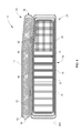
- FIG. 6 is a perspective bottom view of the fluid supply assembly of FIG. 1 showing the conduit coupled to the coverlet, the fluid supply housing, and the controller;
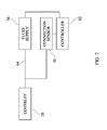
- FIG. 7 is a block diagram of the fluid supply assembly of FIG. 6 ;
- FIG. 8 is a front view of the conduit connector of the conduit of FIG. 6 showing the connection sensor.
- One illustrative embodiment of the present disclosure includes a person support surface with a non-powered mattress and a coverlet coupled to the non-powered mattress having a vapor permeable and air impermeable person contacting surface and mattress contacting surface configured to exhaust heat and moisture communicated through the person contacting surface out an outlet in the coverlet.
- Another illustrative embodiment includes a fluid supply assembly with conduit and a fluid supply configured to be activated/deactivated when the conduit is coupled to a person-support surface.
- FIGS. 1-8 A person-support system 10 according to one illustrative embodiment of the current disclosure is shown in FIGS. 1-8 .
- the person-support system 10 includes person-support apparatus 12 , a person-support surface 14 supported on the person-support apparatus 12 , and a fluid supply assembly 16 in communication with the person-support surface 14 .
- the fluid supply assembly 16 and the person-support surface 14 are part of a mattress replacement system.
- the person-support apparatus 12 includes a lower frame 18 , supports 20 or lift mechanisms 20 coupled to the lower frame 18 , and an upper frame 22 movably supported above the lower frame 18 by the supports 20 as shown in FIG. 1 .
- the person-support apparatus 12 is a hospital bed frame with a first section F 1 or head support section F 1 , where the head of a person (not shown) can be positioned and a second section S 1 or a foot support section S 1 , where the feet of the person (not shown) can be positioned.
- the person-support apparatus 12 can also be a stretcher, an operating room table, a wheel chair, or other person supporting structure.
- the person-support surface 14 includes a non-powered mattress 24 and a coverlet 26 positioned on the mattress 24 as shown in FIGS. 1-4 .
- the non-powered mattress 24 includes a mattress core 28 and a mattress cover 30 .
- the non-powered mattress 24 is or is similar to at least one of the following mattresses sold by Hill-Rom® at 1069 State Route 46 East in Batesville, Ind.: the NP50 Prevention Surface, the NP100 Prevention Surface, the Tempur-Pedic® Mattress, the AccuMax QuantumTM VPC Therapy Surface, and/or the NP200 Wound Surface.
- the foot section S 1 of the non-powered mattress 24 includes a slight gradient to help reduce interface pressure on a person's heel.
- the foot section S 1 of the non-powered mattress 24 is negatively sloped with respect to a reference plane RP 1 as shown in FIG. 4 .
- the mattress core 28 can be composed of a single type of material or a combination of materials and/or devices.
- the mattress core 28 is composed of single density foam as shown in FIG. 2 .
- the mattress core 28 includes multiple zones of high-density foam configured to enhance pressure redistribution as a function of a person's body's proportional differences as shown in FIGS. 1 and 3 - 4 .
- the mattress core 28 can include static air bladders and/or static air bladders with foam contained therewithin.
- the cover 30 can enclose the mattress core 28 and includes a fire barrier 32 , a bottom ticking 34 or durable layer 34 , and a top ticking 36 as shown in FIGS. 2-4 .
- the fire barrier 32 is the innermost layer of the cover 30
- the top ticking 36 is the outermost layer
- the bottom ticking 34 is positioned between the fire barrier 32 and the top ticking 36 and is not coupled to the top ticking 36 .
- the bottom ticking 34 and the top ticking 36 are vapor and air impermeable.
- the top ticking 36 and the bottom ticking 34 are composed of polyurethane coated nylon and the bottom ticking 34 is configured to facilitate movement of the top ticking 36 with respect to the fire barrier 32 .
- the top ticking 36 includes a person-support apparatus engaging surface 38 with a person-support apparatus coupler (not shown), and a coverlet contacting surface 40 with a coverlet coupler 42 as shown in FIGS. 2-4 .
- the coverlet coupler 42 is a zipper and the person-support apparatus coupler is a hook and loop fastener with one portion coupled to the person-support apparatus 12 and the other coupled to the coverlet 26 .
- the coverlet coupler 42 can be a hook and loop fastener, snaps, and/or buttons.
- the coverlet coupler 42 can be elastic loops configured to engage the corners of the mattress 12 .
- the coverlet 26 is configured to regulate the amount of heat and moisture present on the surface of the coverlet 26 by flowing a fluid through the coverlet 26 .
- the coverlet 26 includes a top layer 44 , a bottom layer 46 , an inlet 48 , an outlet 50 , and a 3-dimensionally engineered spacer 52 as shown in FIGS. 2-5 .
- the top layer 44 and the bottom layer 46 are coupled together along their edges to form an inner chamber 54 therebetween. In one illustrative embodiment, the edges of the top layer 44 and the bottom layer 46 are coupled together using RF welding technology.
- the top layer 44 and the bottom layer 46 are both configured to be vapor permeable and air impermeable. This configuration prevents air passing through the coverlet 26 from impinging on the skin of a person positioned on the coverlet 26 while allowing the moisture produced by the person to pass through the top layer 44 and be exhausted with the air passing through the coverlet 26 out the outlet 50 .
- the 3-dimensionally engineered spacer 52 is positioned in the inner chamber 54 and is configured to be air and moisture permeable as shown in FIGS. 2-5 .
- the 3-dimensionally engineered spacer 52 is configured to maintain a path for the air to flow through when a person is supported on the coverlet 26 .
- the 3-dimensionally engineered spacer 52 is Spacenet®.
- the inlet 48 and the outlet 50 are generally located on opposite ends of the coverlet 26 and allow a fluid, such as, air, to be communicated into the inner chamber 54 of the coverlet 26 , and to be exhausted from the coverlet 26 , respectively, as shown in FIGS. 2-5 .
- the inlet 48 is located along the second section S 1 of the coverlet 26 and the outlet 50 is located along the first section F 1 of the coverlet 26 .
- the inlet 48 includes an inlet connector 56 configured to couple to and receive fluid from the fluid supply assembly 16 as shown in FIG. 6 .
- the fluid supply assembly 16 is configured to cooperate with the coverlet 26 to regulate the amount of heat and moisture on at least a portion of the top layer 44 in contact, directly or indirectly, with the skin of a person supported on the person-support surface 14 . Regulation of the heat and moisture levels can help prevent and/or heal undesirable skin conditions, such as, pressure ulcers.
- the fluid supply 16 and coverlet 26 can cooperate to maintain at least one of a surface temperature, a relative surface humidity, and a heat withdrawal capacity of at least a portion of the surface which is in contact, directly or indirectly, with the person within a predefined range, for example, between about 90 ° F.
- the fluid supply assembly 16 includes a fluid supply 58 enclosed within a housing 60 , a controller 62 , and a conduit 64 as shown in FIGS. 6-8 .
- the fluid supply 58 is an air blower and the housing 60 is coupled to the underside of the second section S 1 of the upper frame 22 .
- the housing 60 is integrated into a footboard (not shown) coupled to the person-support apparatus 12 .
- the controller 62 is configured to control the operation of the fluid supply 58 .
- the controller 62 activates and/or deactivates the fluid supply 58 when the conduit 64 is coupled/uncoupled to/from the coverlet 26 .
- the controller 62 can also cause the fluid supply 58 to supply fluid at a predetermined rate and/or adjust the temperature and humidity of the fluid supplied by the fluid supply 58 .
- the controller 62 can activate/deactivate the fluid supply 58 when the conduit 64 is coupled/uncoupled to/from a therapy device, powered mattress, or other pneumatic device or instrument.
- the conduit 64 is configured to facilitate communication of fluid between the fluid supply 58 and the coverlet 26 as shown in FIG. 6 .
- the conduit 64 is configured to be coupled to an outlet (not shown) of the fluid supply 58 and configured to be removably coupled to the inlet connector 56 .
- the conduit 64 includes a conduit connector 66 with a fluid outlet port 68 and a connection sensor 70 as shown in FIG. 8 .
- the connection sensor 70 is configured to sense when the conduit connector 66 is coupled to the inlet connector 56 .
- the connection sensor 70 is a pair of conductive strips configured to engage a conductive strip (not shown) on the inlet connector 56 that electrically connects the pair conductive strips to complete the circuit. This embodiment would not necessarily require a controller to activate/deactivate the fluid supply 58 .
- the sensor 70 is a switch (not shown).
- the conduit connector 66 is not connected from the inlet connector 56 .
- the user connects the conduit connector 66 to the inlet connector 56 .
- the connection sensor 70 senses when the conduit connector 66 and the inlet connector 56 are connected and the controller 62 activates the fluid supply 58 .
- the fluid supply 58 communicates fluid through the conduit 64 to the inlet 48 of the coverlet 26 .
- the fluid flows from the inlet 48 through the inner chamber 54 of the coverlet 26 and is exhausted out the outlet 50 .
- heat and moisture communicated through the upper layer 44 and/or bottom layer 56 is absorbed by the fluid flow and exhausted with the fluid out the outlet 50 .
- a person-support surface comprises a non powered mattress and a coverlet positionable on the non powered mattress.
- the coverlet includes an entry positioned at a first end of the coverlet, an exit positioned at a second end of the coverlet, an upper air impermeable layer, and a lower air impermeable layer coupled to the upper air impermeable layer to form an air flow path along the coverlet between the entry and the exit.
- the upper air impermeable layer is a vapor permeable and water resistant fabric and the lower air impermeable layer is a vapor permeable and water resistant fabric.
- a person-support surface comprises a non powered mattress, a topper, and an air supply.
- the non powered mattress includes a mattress core substantially enclosed within an air and vapor impermeable mattress cover.
- the topper is removably coupled to the non-powered mattress and includes an occupant interfacing surface and a non-powered mattress interfacing surface coupled together to define a chamber therebetween.
- the occupant interfacing surface and the non-powered mattress interfacing surface are vapor permeable and air impermeable.
- the topper has a first opening into the chamber along a first side and a second opening into the chamber along a second side.
- the air supply is in fluid communication with the topper through a conduit. The air enters the chamber through the first opening in the topper, flows through the chamber, and exits the chamber through the second opening.
- the air flow though the topper is configured to exhaust heat and moisture communicated into the chamber through the occupant interfacing surface out through the second opening.
- a fluid supply system comprises a gas blower and a conduit coupled to the gas blower and configured to communicate gas therethrough.
- the conduit includes a connector configured to be removably coupled to a medical device.
- the gas blower is configured to be activated when the conduit is coupled to the medical device.
Abstract
Description
Claims (20)
Priority Applications (5)
| Application Number | Priority Date | Filing Date | Title |
|---|---|---|---|
| US13/099,543 US8856993B2 (en) | 2008-04-15 | 2011-05-03 | Temperature and moisture regulating topper for non-powered person-support surfaces |
| AU2012202456A AU2012202456A1 (en) | 2011-05-03 | 2012-04-27 | Temperature and moisture regulating topper for non-powered person-support surfaces |
| EP12166447.8A EP2520200B1 (en) | 2011-05-03 | 2012-05-02 | Temperature and moistrure regulating topper for non-powered person-support surfaces |
| EP19211012.0A EP3649898A1 (en) | 2011-05-03 | 2012-05-02 | Temperature and moisture regulating topper for non-powered person-support surfaces |
| US14/508,690 US9526348B2 (en) | 2008-04-15 | 2014-10-07 | Person support systems |
Applications Claiming Priority (4)
| Application Number | Priority Date | Filing Date | Title |
|---|---|---|---|
| US4511108P | 2008-04-15 | 2008-04-15 | |
| PCT/US2009/040661 WO2009129306A1 (en) | 2008-04-15 | 2009-04-15 | Microclimate management system |
| US93730610A | 2010-10-11 | 2010-10-11 | |
| US13/099,543 US8856993B2 (en) | 2008-04-15 | 2011-05-03 | Temperature and moisture regulating topper for non-powered person-support surfaces |
Related Parent Applications (3)
| Application Number | Title | Priority Date | Filing Date |
|---|---|---|---|
| PCT/US2009/040661 Continuation-In-Part WO2009129306A1 (en) | 2008-04-15 | 2009-04-15 | Microclimate management system |
| US12/937,306 Continuation-In-Part US20110024076A1 (en) | 2008-04-15 | 2009-04-15 | Microclimate management system |
| US93730610A Continuation-In-Part | 2008-04-15 | 2010-10-11 |
Related Child Applications (1)
| Application Number | Title | Priority Date | Filing Date |
|---|---|---|---|
| US14/508,690 Continuation US9526348B2 (en) | 2008-04-15 | 2014-10-07 | Person support systems |
Publications (2)
| Publication Number | Publication Date |
|---|---|
| US20110247143A1 US20110247143A1 (en) | 2011-10-13 |
| US8856993B2 true US8856993B2 (en) | 2014-10-14 |
Family
ID=44759833
Family Applications (2)
| Application Number | Title | Priority Date | Filing Date |
|---|---|---|---|
| US13/099,543 Active 2030-11-01 US8856993B2 (en) | 2008-04-15 | 2011-05-03 | Temperature and moisture regulating topper for non-powered person-support surfaces |
| US14/508,690 Active US9526348B2 (en) | 2008-04-15 | 2014-10-07 | Person support systems |
Family Applications After (1)
| Application Number | Title | Priority Date | Filing Date |
|---|---|---|---|
| US14/508,690 Active US9526348B2 (en) | 2008-04-15 | 2014-10-07 | Person support systems |
Country Status (1)
| Country | Link |
|---|---|
| US (2) | US8856993B2 (en) |
Cited By (9)
| Publication number | Priority date | Publication date | Assignee | Title |
|---|---|---|---|---|
| US20150089749A1 (en) * | 2008-04-15 | 2015-04-02 | Hill-Rom Services, Inc. | Person support systems |
| US20150296992A1 (en) * | 2014-04-16 | 2015-10-22 | Tempur-Pedic Management, Llc | Support cushions and methods for dissipating heat away from the same |
| US20180140489A1 (en) * | 2009-08-31 | 2018-05-24 | Gentherm Incorporated | Climate-controlled topper member for beds |
| US20200253388A1 (en) * | 2012-02-21 | 2020-08-13 | Hill-Rom Services, Inc. | Topper with targeted fluid flow distribution |
| US10827845B2 (en) | 2017-02-24 | 2020-11-10 | Sealy Technology, Llc | Support cushions including a support insert with a bag for directing air flow, and methods for controlling surface temperature of same |
| US11160386B2 (en) | 2018-06-29 | 2021-11-02 | Tempur World, Llc | Body support cushion with ventilation system |
| US11540964B2 (en) | 2018-02-27 | 2023-01-03 | Hill-Rom Services, Inc. | Patient support surface control, end of life indication, and x-ray cassette sleeve |
| US11559421B2 (en) | 2015-06-25 | 2023-01-24 | Hill-Rom Services, Inc. | Protective dressing with reusable phase-change material cooling insert |
| US11583437B2 (en) | 2018-02-06 | 2023-02-21 | Aspen Surgical Products, Inc. | Reusable warming blanket with phase change material |
Families Citing this family (33)
| Publication number | Priority date | Publication date | Assignee | Title |
|---|---|---|---|---|
| US7877827B2 (en) | 2007-09-10 | 2011-02-01 | Amerigon Incorporated | Operational control schemes for ventilated seat or bed assemblies |
| US8181290B2 (en) | 2008-07-18 | 2012-05-22 | Amerigon Incorporated | Climate controlled bed assembly |
| US9125497B2 (en) * | 2007-10-15 | 2015-09-08 | Gentherm Incorporated | Climate controlled bed assembly with intermediate layer |
| US9131780B2 (en) * | 2012-02-14 | 2015-09-15 | Hill-Rom Services, Inc. | Topper with preferential fluid flow distribution |
| US9572433B2 (en) | 2012-08-15 | 2017-02-21 | Hill-Rom Services, Inc. | Systems and methods for directing fluid flow in a mattress |
| US9392875B2 (en) | 2013-01-18 | 2016-07-19 | Fxi, Inc. | Body support system with combination of pressure redistribution and internal air flow guide(s) for withdrawing heat and moisture away from body reclining on support surface of body support system |
| US9138064B2 (en) | 2013-01-18 | 2015-09-22 | Fxi, Inc. | Mattress with combination of pressure redistribution and internal air flow guides |
| US9433300B2 (en) | 2013-02-28 | 2016-09-06 | Hill-Rom Services, Inc. | Topper for a patient surface |
| US9333136B2 (en) | 2013-02-28 | 2016-05-10 | Hill-Rom Services, Inc. | Sensors in a mattress cover |
| CN106102520B (en) * | 2014-01-13 | 2019-04-09 | 百德盖尔有限责任公司 | Environment bed with heat recovery system |
| EE201400025A (en) * | 2014-06-20 | 2016-01-15 | Osaühing Delux | Bed mattress set |
| US20170150822A1 (en) * | 2014-06-25 | 2017-06-01 | Tempur-Pedic Management, Llc | Support cushion cover assemblies for removing heat and humidity |
| US11833091B2 (en) * | 2014-11-24 | 2023-12-05 | Arjo Ip Holding Ab | Moisture control coverlet |
| US10489661B1 (en) | 2016-03-08 | 2019-11-26 | Ocuvera LLC | Medical environment monitoring system |
| US10600204B1 (en) | 2016-12-28 | 2020-03-24 | Ocuvera | Medical environment bedsore detection and prevention system |
| US11173085B2 (en) | 2017-12-28 | 2021-11-16 | Stryker Corporation | Mattress cover for a mattress providing rotation therapy to a patient |
| US11246775B2 (en) | 2017-12-28 | 2022-02-15 | Stryker Corporation | Patient turning device for a patient support apparatus |
| USD977109S1 (en) | 2018-09-28 | 2023-01-31 | Stryker Corporation | Crib assembly for a patient support |
| USD888964S1 (en) | 2018-09-28 | 2020-06-30 | Stryker Corporation | Crib assembly for a patient support |
| USD877915S1 (en) | 2018-09-28 | 2020-03-10 | Stryker Corporation | Crib assembly |
| USD901940S1 (en) | 2018-09-28 | 2020-11-17 | Stryker Corporation | Patient support |
| USD879966S1 (en) | 2018-09-28 | 2020-03-31 | Stryker Corporation | Crib assembly |
| USD888962S1 (en) | 2018-09-28 | 2020-06-30 | Stryker Corporation | Cover assembly for a patient support |
| USD888963S1 (en) | 2018-09-28 | 2020-06-30 | Stryker Corporation | Cover assembly for a patient support |
| USD892159S1 (en) | 2018-10-31 | 2020-08-04 | Stryker Corporation | Display screen with animated graphical user interface |
| USD893543S1 (en) | 2018-10-31 | 2020-08-18 | Stryker Corporation | Display screen with graphical user interface |
| USD894956S1 (en) | 2018-10-31 | 2020-09-01 | Stryker Corporation | Display screen or portion thereof with graphical user interface |
| USD894957S1 (en) | 2018-10-31 | 2020-09-01 | Stryker Corporation | Display screen or portion thereof with graphical user interface |
| USD894223S1 (en) | 2018-10-31 | 2020-08-25 | Stryker Corporation | Display screen with animated graphical user interface |
| USD894226S1 (en) | 2018-10-31 | 2020-08-25 | Stryker Corporation | Display screen or portion thereof with graphical user interface |
| USD890914S1 (en) | 2018-10-31 | 2020-07-21 | Stryker Corporation | Pump |
| US20210307522A1 (en) * | 2020-04-07 | 2021-10-07 | Lg Electronics Inc. | Bed |
| WO2022187217A1 (en) * | 2021-03-01 | 2022-09-09 | Sleep Number Corporation | Bed sensors |
Citations (39)
| Publication number | Priority date | Publication date | Assignee | Title |
|---|---|---|---|---|
| US2767410A (en) * | 1953-05-25 | 1956-10-23 | Carl F Benson | Mattress with foot hold |
| US4665573A (en) * | 1985-05-16 | 1987-05-19 | Fiore Timothy J | Contoured body support structure |
| US5048137A (en) * | 1990-08-20 | 1991-09-17 | Rogers John E | Edge-shear reduction in body support foam pads |
| US5687438A (en) | 1994-08-04 | 1997-11-18 | Sentech Medical Systems, Inc. | Alternating low air loss pressure overlay for patient bedside chair and mobile wheel chair |
| WO1997047268A1 (en) | 1996-06-14 | 1997-12-18 | Span-America Medical Systems, Inc. | Pressure relief valve vent line mattress system and method |
| US5800480A (en) | 1996-08-30 | 1998-09-01 | Augustine Medical, Inc. | Support apparatus with a plurality of thermal zones providing localized cooling |
| US5882349A (en) | 1995-12-26 | 1999-03-16 | Geomarine Systems, Inc. | Patient moisture control support surface coverlet |
| US6197045B1 (en) | 1999-01-04 | 2001-03-06 | Medivance Incorporated | Cooling/heating pad and system |
| US20020073489A1 (en) * | 2000-07-18 | 2002-06-20 | Span-America Medical System, Inc. | Air-powered low interface pressure support surface |
| US6421859B1 (en) | 1999-06-03 | 2002-07-23 | Kci Licensing, Inc. | Patient support systems with layered fluid support mediums |
| US6442780B1 (en) * | 2000-03-09 | 2002-09-03 | Kci Licensing, Inc. | Mattress with semi-independent pressure relieving pillars |
| US20030145380A1 (en) | 2002-02-06 | 2003-08-07 | Halo Innovations, Inc. | Furniture cover sheet |
| US6730115B1 (en) * | 1996-05-16 | 2004-05-04 | Kci Licensing, Inc. | Cooling system |
| US6855158B2 (en) | 2001-09-11 | 2005-02-15 | Hill-Rom Services, Inc. | Thermo-regulating patient support structure |
| US20050273941A1 (en) | 2004-06-04 | 2005-12-15 | Stolpmann James R | Mattress with heel pressure relief portion |
| US20060168736A1 (en) * | 2004-04-30 | 2006-08-03 | Meyer Eric R | Pressure relief surface |
| US20070056101A1 (en) | 2005-09-08 | 2007-03-15 | Ajay Mahajan | Sensor based mattress/seat for monitoring pressure, temperature and sweat concentration to prevent pressure ulcerations |
| US20070261548A1 (en) * | 2006-05-11 | 2007-11-15 | Kci Licensing, Inc., Legal Department, Intellectual Property | Multi-layered support system |
| US20070266499A1 (en) * | 2006-05-09 | 2007-11-22 | Hill-Rom Services, Inc. | Pulmonary mattress |
| US20080028533A1 (en) * | 2006-08-04 | 2008-02-07 | Stacy Richard B | Patient Support |
| US20080047325A1 (en) | 2006-07-17 | 2008-02-28 | Kci Licensing, Inc., Legal Department, Intellectual Property | Measurement of moisture vapor transfer rate |
| US20080120780A1 (en) * | 2006-11-16 | 2008-05-29 | Stryker Corporation | Patient support surface with turn-assist |
| US20080141463A1 (en) * | 2006-11-16 | 2008-06-19 | Stryker Corporation | Patient support surface with turn-assist |
| CA2411539C (en) | 2000-06-26 | 2008-09-23 | Thomas P. Stewart | Automatic patient control device |
| US20080263776A1 (en) | 2007-04-30 | 2008-10-30 | Span-America Medical Systems, Inc. | Low air loss moisture control mattress overlay |
| US20090000031A1 (en) | 2007-06-29 | 2009-01-01 | Steve Feher | Multiple convective cushion seating and sleeping systems and methods |
| US7480953B2 (en) | 1998-05-06 | 2009-01-27 | Hill-Rom Services, Inc. | Patient support |
| US20090217460A1 (en) * | 2005-07-08 | 2009-09-03 | Bobey John A | Patient support |
| US20090222996A1 (en) * | 2006-02-02 | 2009-09-10 | Bg Industries, Llc | Pressure reduction healthcare mattress system |
| WO2009129306A1 (en) | 2008-04-15 | 2009-10-22 | Hill-Room Services Inc. | Microclimate management system |
| US7641623B2 (en) | 2003-04-11 | 2010-01-05 | Hill-Rom Services, Inc. | System for compression therapy with patient support |
| US20100122417A1 (en) * | 2008-11-19 | 2010-05-20 | Kci Licensing, Inc. | Multi-Layered Support System |
| US20100274331A1 (en) * | 2009-04-28 | 2010-10-28 | Rachel Williamson | Microclimate management system |
| EP2298264A2 (en) | 2009-09-18 | 2011-03-23 | Hill-Rom Services, Inc. | Patient support surface index control |
| US20110247143A1 (en) * | 2008-04-15 | 2011-10-13 | Richards Sandy M | Temperature and moisture regulating topper for non-powered person-support surfaces |
| US20120012277A1 (en) * | 2010-07-15 | 2012-01-19 | Lachenbruch Charles A | Method and System for Controlling Evaporative and Heat Withdrawal Performance of an Occupant Support Surface |
| US20130074272A1 (en) * | 2011-09-23 | 2013-03-28 | Charles A. Lachenbruch | Moisture Management and Transport Cover |
| US20130081205A1 (en) * | 2011-09-30 | 2013-04-04 | Michael M. Frondorf | Person support surface |
| US20140068869A1 (en) * | 2012-01-17 | 2014-03-13 | Stryker Corporation | Patient/invalid support with pressure reducing system |
Family Cites Families (28)
| Publication number | Priority date | Publication date | Assignee | Title |
|---|---|---|---|---|
| US2093834A (en) * | 1934-04-30 | 1937-09-21 | Gen Motors Corp | Refrigerating apparatus |
| US2235966A (en) * | 1935-06-27 | 1941-03-25 | Gen Motors Corp | Refrigerating apparatus |
| US2493067A (en) * | 1945-09-08 | 1950-01-03 | Louis J Goldsmith | Mattress |
| US2617915A (en) * | 1951-04-10 | 1952-11-11 | Blair Gerhardt | Air impelling and heating apparatus |
| US3230556A (en) * | 1962-05-07 | 1966-01-25 | Shippee Wiusor | Construction for maintaining a controlled temperature environment in a bed |
| US3427431A (en) * | 1966-12-13 | 1969-02-11 | Raphael Joseph Costanzo | Sleeping bag and heater therefor |
| US3713182A (en) * | 1971-05-26 | 1973-01-30 | Neal H Mc | Bedclothes elevator and bed warmer |
| US4238689A (en) | 1979-02-28 | 1980-12-09 | Beamco Co., Inc. | Vacuum cleaner control system |
| US4660388A (en) * | 1984-05-24 | 1987-04-28 | Greene Jr George J | Cooling cover |
| FI74829C (en) | 1986-10-01 | 1988-03-10 | Allaway Oy | Method for controlling a plant such as vacuum cleaner, central vacuum cleaner, mechanical air conditioning system or the like. |
| CH672982A5 (en) | 1987-06-18 | 1990-01-31 | Steinemann Ag | |
| US4867230A (en) * | 1988-04-11 | 1989-09-19 | Gene Voss | Convection blanket warmer |
| DE3822633A1 (en) | 1988-07-05 | 1990-01-18 | Bsg Schalttechnik | DEVICE WITH AUTOMATIC SWITCH-ON FOR A SUB-DEVICE WHEN STARTING A MAIN DEVICE |
| US4959877A (en) * | 1989-11-24 | 1990-10-02 | Covil Donald M | All-season floating blanket |
| US5125238A (en) * | 1991-04-29 | 1992-06-30 | Progressive Dynamics, Inc. | Patient warming or cooling blanket |
| US5349146A (en) | 1992-02-11 | 1994-09-20 | Lindsay Manufacturing, Inc. | Combination electrical and suction hose wall outlet |
| US5493742A (en) * | 1994-05-10 | 1996-02-27 | Lake Medical Products, Inc. | Ventilating air mattress with an inflating quilted pad |
| US5584084A (en) * | 1994-11-14 | 1996-12-17 | Lake Medical Products, Inc. | Bed system having programmable air pump with electrically interlocking connectors |
| US6021533A (en) * | 1997-08-25 | 2000-02-08 | Hill-Rom, Inc. | Mattress apparatus having a siderail down sensor |
| US6044717A (en) * | 1998-09-28 | 2000-04-04 | Xerox Corporation | Pressure and force profile sensor and method for detecting pressure |
| EP2181685B1 (en) | 2002-09-06 | 2014-05-14 | Hill-Rom Services, Inc. | Hospital bed with controlled inflatable portion of patient support |
| US20060085911A1 (en) * | 2004-10-21 | 2006-04-27 | Tompkins Kurt W | Portable ventilation system |
| EP1671563B1 (en) * | 2004-12-15 | 2008-02-13 | Hill-Rom Services, Inc. | Connector apparatus for an air mattress |
| US8276222B1 (en) * | 2005-01-14 | 2012-10-02 | Smart Medical Technology, Inc. | Patient transfer kit |
| US9241580B2 (en) * | 2005-01-14 | 2016-01-26 | Sage Products, Llc | Body transport apparatus with integrated handles |
| US7114204B2 (en) * | 2005-01-14 | 2006-10-03 | Smart Medical Technology, Inc. | Method and apparatus for transferring patients |
| US7735164B1 (en) * | 2005-01-14 | 2010-06-15 | Smart Medical Technology, Inc. | Disposable patient transfer mattress |
| US9125777B2 (en) * | 2005-01-14 | 2015-09-08 | Sage Products, Llc | Body transport apparatus |
-
2011
- 2011-05-03 US US13/099,543 patent/US8856993B2/en active Active
-
2014
- 2014-10-07 US US14/508,690 patent/US9526348B2/en active Active
Patent Citations (64)
| Publication number | Priority date | Publication date | Assignee | Title |
|---|---|---|---|---|
| US2767410A (en) * | 1953-05-25 | 1956-10-23 | Carl F Benson | Mattress with foot hold |
| US4665573A (en) * | 1985-05-16 | 1987-05-19 | Fiore Timothy J | Contoured body support structure |
| US5048137A (en) * | 1990-08-20 | 1991-09-17 | Rogers John E | Edge-shear reduction in body support foam pads |
| US5687438A (en) | 1994-08-04 | 1997-11-18 | Sentech Medical Systems, Inc. | Alternating low air loss pressure overlay for patient bedside chair and mobile wheel chair |
| US5882349A (en) | 1995-12-26 | 1999-03-16 | Geomarine Systems, Inc. | Patient moisture control support surface coverlet |
| US6730115B1 (en) * | 1996-05-16 | 2004-05-04 | Kci Licensing, Inc. | Cooling system |
| WO1997047268A1 (en) | 1996-06-14 | 1997-12-18 | Span-America Medical Systems, Inc. | Pressure relief valve vent line mattress system and method |
| US5800480A (en) | 1996-08-30 | 1998-09-01 | Augustine Medical, Inc. | Support apparatus with a plurality of thermal zones providing localized cooling |
| US7480953B2 (en) | 1998-05-06 | 2009-01-27 | Hill-Rom Services, Inc. | Patient support |
| US6197045B1 (en) | 1999-01-04 | 2001-03-06 | Medivance Incorporated | Cooling/heating pad and system |
| US6421859B1 (en) | 1999-06-03 | 2002-07-23 | Kci Licensing, Inc. | Patient support systems with layered fluid support mediums |
| US6874185B1 (en) * | 2000-03-09 | 2005-04-05 | Kci Licensing, Inc. | Mattress with semi-independent pressure relieving |
| US6442780B1 (en) * | 2000-03-09 | 2002-09-03 | Kci Licensing, Inc. | Mattress with semi-independent pressure relieving pillars |
| CA2411539C (en) | 2000-06-26 | 2008-09-23 | Thomas P. Stewart | Automatic patient control device |
| US6782574B2 (en) * | 2000-07-18 | 2004-08-31 | Span-America Medical Systems, Inc. | Air-powered low interface pressure support surface |
| US7296315B2 (en) | 2000-07-18 | 2007-11-20 | Span-America Medical Systems, Inc. | Air-powered low interface pressure support surface |
| US20020073489A1 (en) * | 2000-07-18 | 2002-06-20 | Span-America Medical System, Inc. | Air-powered low interface pressure support surface |
| US6855158B2 (en) | 2001-09-11 | 2005-02-15 | Hill-Rom Services, Inc. | Thermo-regulating patient support structure |
| US20030145380A1 (en) | 2002-02-06 | 2003-08-07 | Halo Innovations, Inc. | Furniture cover sheet |
| US7641623B2 (en) | 2003-04-11 | 2010-01-05 | Hill-Rom Services, Inc. | System for compression therapy with patient support |
| US7937791B2 (en) * | 2004-04-30 | 2011-05-10 | Hill-Rom Services, Inc. | Pressure relief surface |
| US20110209289A1 (en) * | 2004-04-30 | 2011-09-01 | Meyer Eric R | Pressure relief surface |
| US8196240B2 (en) * | 2004-04-30 | 2012-06-12 | Hill-Rom Services, Inc. | Pressure relief surface |
| US20060168736A1 (en) * | 2004-04-30 | 2006-08-03 | Meyer Eric R | Pressure relief surface |
| US20090119846A1 (en) * | 2004-04-30 | 2009-05-14 | Meyer Eric R | Pressure relief surface |
| US7469436B2 (en) * | 2004-04-30 | 2008-12-30 | Hill-Rom Services, Inc. | Pressure relief surface |
| US20050273941A1 (en) | 2004-06-04 | 2005-12-15 | Stolpmann James R | Mattress with heel pressure relief portion |
| US20090217460A1 (en) * | 2005-07-08 | 2009-09-03 | Bobey John A | Patient support |
| US20070056101A1 (en) | 2005-09-08 | 2007-03-15 | Ajay Mahajan | Sensor based mattress/seat for monitoring pressure, temperature and sweat concentration to prevent pressure ulcerations |
| US8196241B2 (en) * | 2006-02-02 | 2012-06-12 | Bg Industries, Llc. | Pressure reduction healthcare mattress system |
| US20090222996A1 (en) * | 2006-02-02 | 2009-09-10 | Bg Industries, Llc | Pressure reduction healthcare mattress system |
| US7975335B2 (en) * | 2006-05-09 | 2011-07-12 | Hill-Rom Services, Inc. | Pulmonary mattress |
| US20070266499A1 (en) * | 2006-05-09 | 2007-11-22 | Hill-Rom Services, Inc. | Pulmonary mattress |
| US8474074B2 (en) * | 2006-05-09 | 2013-07-02 | Hill-Rom Services, Inc. | Pulmonary mattress |
| US20110258780A1 (en) * | 2006-05-09 | 2011-10-27 | O'keefe Christopher R | Pulmonary mattress |
| US8372182B2 (en) * | 2006-05-11 | 2013-02-12 | Huntleigh Technology Limited | Multi-layered support system |
| US20120144584A1 (en) * | 2006-05-11 | 2012-06-14 | Kci Licensing, Inc. | Multi-layered support system |
| US20110219548A1 (en) * | 2006-05-11 | 2011-09-15 | Kci Licensing, Inc. | Multi-Layered Support System |
| US7914611B2 (en) * | 2006-05-11 | 2011-03-29 | Kci Licensing, Inc. | Multi-layered support system |
| US20070261548A1 (en) * | 2006-05-11 | 2007-11-15 | Kci Licensing, Inc., Legal Department, Intellectual Property | Multi-layered support system |
| US8118920B2 (en) * | 2006-05-11 | 2012-02-21 | Kci Licensing, Inc. | Multi-layered support system |
| US20080047325A1 (en) | 2006-07-17 | 2008-02-28 | Kci Licensing, Inc., Legal Department, Intellectual Property | Measurement of moisture vapor transfer rate |
| US20100132116A1 (en) * | 2006-08-04 | 2010-06-03 | Stacy Richard B | Patient Support with Orientation Sensitive Air Bladder Control |
| US7657956B2 (en) * | 2006-08-04 | 2010-02-09 | Hill-Rom Services, Inc. | Patient support |
| US20080028533A1 (en) * | 2006-08-04 | 2008-02-07 | Stacy Richard B | Patient Support |
| US8006333B2 (en) * | 2006-11-16 | 2011-08-30 | Stryker Corporation | Patient support surface with turn-assist |
| US20080141463A1 (en) * | 2006-11-16 | 2008-06-19 | Stryker Corporation | Patient support surface with turn-assist |
| US8201292B2 (en) * | 2006-11-16 | 2012-06-19 | Stryker Corporation | Patient support surface with turn-assist |
| US20080120780A1 (en) * | 2006-11-16 | 2008-05-29 | Stryker Corporation | Patient support surface with turn-assist |
| US20080263776A1 (en) | 2007-04-30 | 2008-10-30 | Span-America Medical Systems, Inc. | Low air loss moisture control mattress overlay |
| US20090000031A1 (en) | 2007-06-29 | 2009-01-01 | Steve Feher | Multiple convective cushion seating and sleeping systems and methods |
| WO2009129306A1 (en) | 2008-04-15 | 2009-10-22 | Hill-Room Services Inc. | Microclimate management system |
| US20110024076A1 (en) * | 2008-04-15 | 2011-02-03 | Hill-Rom Services, Inc. | Microclimate management system |
| US20110247143A1 (en) * | 2008-04-15 | 2011-10-13 | Richards Sandy M | Temperature and moisture regulating topper for non-powered person-support surfaces |
| US20100122417A1 (en) * | 2008-11-19 | 2010-05-20 | Kci Licensing, Inc. | Multi-Layered Support System |
| US20100274331A1 (en) * | 2009-04-28 | 2010-10-28 | Rachel Williamson | Microclimate management system |
| EP2298264A2 (en) | 2009-09-18 | 2011-03-23 | Hill-Rom Services, Inc. | Patient support surface index control |
| US20110068939A1 (en) * | 2009-09-18 | 2011-03-24 | Lachenbruch Charles A | Patient support surface index control |
| US8531307B2 (en) * | 2009-09-18 | 2013-09-10 | Hill-Rom Services, Inc. | Patient support surface index control |
| US20140007346A1 (en) * | 2009-09-18 | 2014-01-09 | Hill-Rom Services, Inc | Fluid supply control for patient support surface |
| US20120012277A1 (en) * | 2010-07-15 | 2012-01-19 | Lachenbruch Charles A | Method and System for Controlling Evaporative and Heat Withdrawal Performance of an Occupant Support Surface |
| US20130074272A1 (en) * | 2011-09-23 | 2013-03-28 | Charles A. Lachenbruch | Moisture Management and Transport Cover |
| US20130081205A1 (en) * | 2011-09-30 | 2013-04-04 | Michael M. Frondorf | Person support surface |
| US20140068869A1 (en) * | 2012-01-17 | 2014-03-13 | Stryker Corporation | Patient/invalid support with pressure reducing system |
Non-Patent Citations (5)
| Title |
|---|
| CareSelections by Hill-Rom; Wound Care Therapy Products; Brochure; 132952; Mar. 4, 2005. |
| European Search Report for EP Application 12166447.8; Place of Search-Munich; Date of completion of the search-Jul. 17, 2013. |
| European Search Report for EP Application 12166447.8; Place of Search—Munich; Date of completion of the search—Jul. 17, 2013. |
| Hill-Rom Advanced Surface Technology; Advanced Surface Technology for Positive Patient Outcomes; Brochure; Nov. 9, 2007. |
| The Joint Commission Journal on Quality and Patient Safety; Eliminating Facility-Acquired Pressure Ulcers at Ascension Health; Wanda Gibbons, R.N., H.H.A.; Helana T. Shanks, R.N.; Pam Kleinhelter, R.N., M.S.N.; Polly Jones, L.C.S.W.; Joint Commission on Accreditation of Healthcare Organizations, Oakbrook Terrace, IL 60181; Sep. 2006, vol. 32 No. 9. |
Cited By (19)
| Publication number | Priority date | Publication date | Assignee | Title |
|---|---|---|---|---|
| US9526348B2 (en) * | 2008-04-15 | 2016-12-27 | Hill-Rom Services, Inc. | Person support systems |
| US20150089749A1 (en) * | 2008-04-15 | 2015-04-02 | Hill-Rom Services, Inc. | Person support systems |
| US11020298B2 (en) | 2009-08-31 | 2021-06-01 | Sleep Number Corporation | Climate-controlled topper member for beds |
| US11642265B2 (en) | 2009-08-31 | 2023-05-09 | Sleep Number Corporation | Climate-controlled topper member for beds |
| US20180140489A1 (en) * | 2009-08-31 | 2018-05-24 | Gentherm Incorporated | Climate-controlled topper member for beds |
| US10675198B2 (en) * | 2009-08-31 | 2020-06-09 | Gentherm Incorporated | Climate-controlled topper member for beds |
| US11045371B2 (en) | 2009-08-31 | 2021-06-29 | Sleep Number Corporation | Climate-controlled topper member for beds |
| US11938071B2 (en) | 2009-08-31 | 2024-03-26 | Sleep Number Corporation | Climate-controlled bed system |
| US11389356B2 (en) | 2009-08-31 | 2022-07-19 | Sleep Number Corporation | Climate-controlled topper member for beds |
| US11903888B2 (en) | 2009-08-31 | 2024-02-20 | Sleep Number Corporation | Conditioner mat system for use with a bed assembly |
| US20200253388A1 (en) * | 2012-02-21 | 2020-08-13 | Hill-Rom Services, Inc. | Topper with targeted fluid flow distribution |
| US11278125B2 (en) | 2012-02-21 | 2022-03-22 | Hill-Rom Services, Inc. | Topper with targeted fluid flow distribution |
| US9596945B2 (en) * | 2014-04-16 | 2017-03-21 | Tempur-Pedic Management, Llc | Support cushions and methods for dissipating heat away from the same |
| US20150296992A1 (en) * | 2014-04-16 | 2015-10-22 | Tempur-Pedic Management, Llc | Support cushions and methods for dissipating heat away from the same |
| US11559421B2 (en) | 2015-06-25 | 2023-01-24 | Hill-Rom Services, Inc. | Protective dressing with reusable phase-change material cooling insert |
| US10827845B2 (en) | 2017-02-24 | 2020-11-10 | Sealy Technology, Llc | Support cushions including a support insert with a bag for directing air flow, and methods for controlling surface temperature of same |
| US11583437B2 (en) | 2018-02-06 | 2023-02-21 | Aspen Surgical Products, Inc. | Reusable warming blanket with phase change material |
| US11540964B2 (en) | 2018-02-27 | 2023-01-03 | Hill-Rom Services, Inc. | Patient support surface control, end of life indication, and x-ray cassette sleeve |
| US11160386B2 (en) | 2018-06-29 | 2021-11-02 | Tempur World, Llc | Body support cushion with ventilation system |
Also Published As
| Publication number | Publication date |
|---|---|
| US20150089749A1 (en) | 2015-04-02 |
| US9526348B2 (en) | 2016-12-27 |
| US20110247143A1 (en) | 2011-10-13 |
Similar Documents
| Publication | Publication Date | Title |
|---|---|---|
| US8856993B2 (en) | Temperature and moisture regulating topper for non-powered person-support surfaces | |
| US10507147B2 (en) | Patient support | |
| US7469436B2 (en) | Pressure relief surface | |
| US7469432B2 (en) | Method and apparatus for improving air flow under a patient | |
| US8201292B2 (en) | Patient support surface with turn-assist | |
| US8146191B2 (en) | Patient support | |
| US8601620B2 (en) | Cover system for a patient support surface | |
| US9433300B2 (en) | Topper for a patient surface | |
| US9907408B2 (en) | Multi-layered support system | |
| US9538853B2 (en) | Multi-layer support system | |
| US20110010855A1 (en) | Therapy and Low Air Loss Universal Coverlet | |
| US20110054366A1 (en) | Therapeutic pressure system | |
| CA2316461C (en) | Coverlet for an air bed | |
| EP2520200B1 (en) | Temperature and moistrure regulating topper for non-powered person-support surfaces | |
| CN109276385B (en) | Patient cooling system responsive to head height | |
| US20200253387A1 (en) | Method for optimizing skin cooling level of an occupant support surface | |
| WO2024010734A1 (en) | Patient support apparatus with patient support surfaces therefor |
Legal Events
| Date | Code | Title | Description |
|---|---|---|---|
| AS | Assignment |
Owner name: HILL-ROM SERVICES, INC, INDIANA Free format text: ASSIGNMENT OF ASSIGNORS INTEREST;ASSIGNORS:RICHARDS, SANDY M.;ALSAEEDE, SAM M.;KERR, ANDREW;AND OTHERS;SIGNING DATES FROM 20110503 TO 20110615;REEL/FRAME:026490/0549 |
|
| STCF | Information on status: patent grant |
Free format text: PATENTED CASE |
|
| AS | Assignment |
Owner name: JPMORGAN CHASE BANK, N.A., AS COLLATERAL AGENT, ILLINOIS Free format text: SECURITY INTEREST;ASSIGNORS:ALLEN MEDICAL SYSTEMS, INC.;HILL-ROM SERVICES, INC.;ASPEN SURGICAL PRODUCTS, INC.;AND OTHERS;REEL/FRAME:036582/0123 Effective date: 20150908 Owner name: JPMORGAN CHASE BANK, N.A., AS COLLATERAL AGENT, IL Free format text: SECURITY INTEREST;ASSIGNORS:ALLEN MEDICAL SYSTEMS, INC.;HILL-ROM SERVICES, INC.;ASPEN SURGICAL PRODUCTS, INC.;AND OTHERS;REEL/FRAME:036582/0123 Effective date: 20150908 |
|
| AS | Assignment |
Owner name: JPMORGAN CHASE BANK, N.A., AS COLLATERAL AGENT, ILLINOIS Free format text: SECURITY AGREEMENT;ASSIGNORS:HILL-ROM SERVICES, INC.;ASPEN SURGICAL PRODUCTS, INC.;ALLEN MEDICAL SYSTEMS, INC.;AND OTHERS;REEL/FRAME:040145/0445 Effective date: 20160921 Owner name: JPMORGAN CHASE BANK, N.A., AS COLLATERAL AGENT, IL Free format text: SECURITY AGREEMENT;ASSIGNORS:HILL-ROM SERVICES, INC.;ASPEN SURGICAL PRODUCTS, INC.;ALLEN MEDICAL SYSTEMS, INC.;AND OTHERS;REEL/FRAME:040145/0445 Effective date: 20160921 |
|
| MAFP | Maintenance fee payment |
Free format text: PAYMENT OF MAINTENANCE FEE, 4TH YEAR, LARGE ENTITY (ORIGINAL EVENT CODE: M1551) Year of fee payment: 4 |
|
| AS | Assignment |
Owner name: HILL-ROM SERVICES, INC., ILLINOIS Free format text: RELEASE BY SECURED PARTY;ASSIGNOR:JPMORGAN CHASE BANK, N.A.;REEL/FRAME:050254/0513 Effective date: 20190830 Owner name: HILL-ROM, INC., ILLINOIS Free format text: RELEASE BY SECURED PARTY;ASSIGNOR:JPMORGAN CHASE BANK, N.A.;REEL/FRAME:050254/0513 Effective date: 20190830 Owner name: VOALTE, INC., FLORIDA Free format text: RELEASE BY SECURED PARTY;ASSIGNOR:JPMORGAN CHASE BANK, N.A.;REEL/FRAME:050254/0513 Effective date: 20190830 Owner name: ALLEN MEDICAL SYSTEMS, INC., ILLINOIS Free format text: RELEASE BY SECURED PARTY;ASSIGNOR:JPMORGAN CHASE BANK, N.A.;REEL/FRAME:050254/0513 Effective date: 20190830 Owner name: MORTARA INSTRUMENT SERVICES, INC., WISCONSIN Free format text: RELEASE BY SECURED PARTY;ASSIGNOR:JPMORGAN CHASE BANK, N.A.;REEL/FRAME:050254/0513 Effective date: 20190830 Owner name: HILL-ROM COMPANY, INC., ILLINOIS Free format text: RELEASE BY SECURED PARTY;ASSIGNOR:JPMORGAN CHASE BANK, N.A.;REEL/FRAME:050254/0513 Effective date: 20190830 Owner name: ANODYNE MEDICAL DEVICE, INC., FLORIDA Free format text: RELEASE BY SECURED PARTY;ASSIGNOR:JPMORGAN CHASE BANK, N.A.;REEL/FRAME:050254/0513 Effective date: 20190830 Owner name: WELCH ALLYN, INC., NEW YORK Free format text: RELEASE BY SECURED PARTY;ASSIGNOR:JPMORGAN CHASE BANK, N.A.;REEL/FRAME:050254/0513 Effective date: 20190830 Owner name: MORTARA INSTRUMENT, INC., WISCONSIN Free format text: RELEASE BY SECURED PARTY;ASSIGNOR:JPMORGAN CHASE BANK, N.A.;REEL/FRAME:050254/0513 Effective date: 20190830 |
|
| AS | Assignment |
Owner name: JPMORGAN CHASE BANK, N.A., ILLINOIS Free format text: SECURITY AGREEMENT;ASSIGNORS:HILL-ROM HOLDINGS, INC.;HILL-ROM, INC.;HILL-ROM SERVICES, INC.;AND OTHERS;REEL/FRAME:050260/0644 Effective date: 20190830 |
|
| AS | Assignment |
Owner name: HILL-ROM HOLDINGS, INC., ILLINOIS Free format text: RELEASE OF SECURITY INTEREST AT REEL/FRAME 050260/0644;ASSIGNOR:JPMORGAN CHASE BANK, N.A.;REEL/FRAME:058517/0001 Effective date: 20211213 Owner name: BARDY DIAGNOSTICS, INC., ILLINOIS Free format text: RELEASE OF SECURITY INTEREST AT REEL/FRAME 050260/0644;ASSIGNOR:JPMORGAN CHASE BANK, N.A.;REEL/FRAME:058517/0001 Effective date: 20211213 Owner name: VOALTE, INC., FLORIDA Free format text: RELEASE OF SECURITY INTEREST AT REEL/FRAME 050260/0644;ASSIGNOR:JPMORGAN CHASE BANK, N.A.;REEL/FRAME:058517/0001 Effective date: 20211213 Owner name: HILL-ROM, INC., ILLINOIS Free format text: RELEASE OF SECURITY INTEREST AT REEL/FRAME 050260/0644;ASSIGNOR:JPMORGAN CHASE BANK, N.A.;REEL/FRAME:058517/0001 Effective date: 20211213 Owner name: WELCH ALLYN, INC., NEW YORK Free format text: RELEASE OF SECURITY INTEREST AT REEL/FRAME 050260/0644;ASSIGNOR:JPMORGAN CHASE BANK, N.A.;REEL/FRAME:058517/0001 Effective date: 20211213 Owner name: ALLEN MEDICAL SYSTEMS, INC., ILLINOIS Free format text: RELEASE OF SECURITY INTEREST AT REEL/FRAME 050260/0644;ASSIGNOR:JPMORGAN CHASE BANK, N.A.;REEL/FRAME:058517/0001 Effective date: 20211213 Owner name: HILL-ROM SERVICES, INC., ILLINOIS Free format text: RELEASE OF SECURITY INTEREST AT REEL/FRAME 050260/0644;ASSIGNOR:JPMORGAN CHASE BANK, N.A.;REEL/FRAME:058517/0001 Effective date: 20211213 Owner name: BREATHE TECHNOLOGIES, INC., CALIFORNIA Free format text: RELEASE OF SECURITY INTEREST AT REEL/FRAME 050260/0644;ASSIGNOR:JPMORGAN CHASE BANK, N.A.;REEL/FRAME:058517/0001 Effective date: 20211213 |
|
| MAFP | Maintenance fee payment |
Free format text: PAYMENT OF MAINTENANCE FEE, 8TH YEAR, LARGE ENTITY (ORIGINAL EVENT CODE: M1552); ENTITY STATUS OF PATENT OWNER: LARGE ENTITY Year of fee payment: 8 |