US8858608B2 - Lubrication apparatus for a delivery and deployment device - Google Patents
Lubrication apparatus for a delivery and deployment device Download PDFInfo
- Publication number
- US8858608B2 US8858608B2 US12/330,833 US33083308A US8858608B2 US 8858608 B2 US8858608 B2 US 8858608B2 US 33083308 A US33083308 A US 33083308A US 8858608 B2 US8858608 B2 US 8858608B2
- Authority
- US
- United States
- Prior art keywords
- dilator
- valve
- sheath
- lubricant
- grooves
- Prior art date
- Legal status (The legal status is an assumption and is not a legal conclusion. Google has not performed a legal analysis and makes no representation as to the accuracy of the status listed.)
- Active, expires
Links
- 238000005461 lubrication Methods 0.000 title claims abstract description 33
- 230000007246 mechanism Effects 0.000 claims abstract description 38
- 239000000314 lubricant Substances 0.000 claims description 61
- 238000000034 method Methods 0.000 claims description 37
- 238000000576 coating method Methods 0.000 claims description 17
- 239000011248 coating agent Substances 0.000 claims description 16
- -1 polyvinylpyrolidone Polymers 0.000 claims description 13
- KIUKXJAPPMFGSW-DNGZLQJQSA-N (2S,3S,4S,5R,6R)-6-[(2S,3R,4R,5S,6R)-3-Acetamido-2-[(2S,3S,4R,5R,6R)-6-[(2R,3R,4R,5S,6R)-3-acetamido-2,5-dihydroxy-6-(hydroxymethyl)oxan-4-yl]oxy-2-carboxy-4,5-dihydroxyoxan-3-yl]oxy-5-hydroxy-6-(hydroxymethyl)oxan-4-yl]oxy-3,4,5-trihydroxyoxane-2-carboxylic acid Chemical compound CC(=O)N[C@H]1[C@H](O)O[C@H](CO)[C@@H](O)[C@@H]1O[C@H]1[C@H](O)[C@@H](O)[C@H](O[C@H]2[C@@H]([C@@H](O[C@H]3[C@@H]([C@@H](O)[C@H](O)[C@H](O3)C(O)=O)O)[C@H](O)[C@@H](CO)O2)NC(C)=O)[C@@H](C(O)=O)O1 KIUKXJAPPMFGSW-DNGZLQJQSA-N 0.000 claims description 10
- 229920002674 hyaluronan Polymers 0.000 claims description 10
- 229960003160 hyaluronic acid Drugs 0.000 claims description 10
- 230000002439 hemostatic effect Effects 0.000 claims description 9
- 230000001050 lubricating effect Effects 0.000 claims description 7
- 229920002401 polyacrylamide Polymers 0.000 claims description 5
- 238000001704 evaporation Methods 0.000 claims description 3
- 239000002904 solvent Substances 0.000 claims description 3
- 238000002474 experimental method Methods 0.000 description 15
- XLYOFNOQVPJJNP-UHFFFAOYSA-N water Substances O XLYOFNOQVPJJNP-UHFFFAOYSA-N 0.000 description 12
- 230000003068 static effect Effects 0.000 description 10
- 229920001296 polysiloxane Polymers 0.000 description 8
- FAPWRFPIFSIZLT-UHFFFAOYSA-M Sodium chloride Chemical compound [Na+].[Cl-] FAPWRFPIFSIZLT-UHFFFAOYSA-M 0.000 description 7
- 239000000463 material Substances 0.000 description 7
- 230000009467 reduction Effects 0.000 description 7
- 239000000243 solution Substances 0.000 description 7
- 230000002829 reductive effect Effects 0.000 description 5
- 230000006870 function Effects 0.000 description 4
- 230000023597 hemostasis Effects 0.000 description 4
- 229920001343 polytetrafluoroethylene Polymers 0.000 description 4
- 239000004810 polytetrafluoroethylene Substances 0.000 description 4
- 238000004873 anchoring Methods 0.000 description 3
- 230000008901 benefit Effects 0.000 description 3
- 239000008280 blood Substances 0.000 description 3
- 210000004369 blood Anatomy 0.000 description 3
- 229920002635 polyurethane Polymers 0.000 description 3
- 239000004814 polyurethane Substances 0.000 description 3
- 238000009736 wetting Methods 0.000 description 3
- LFQSCWFLJHTTHZ-UHFFFAOYSA-N Ethanol Chemical compound CCO LFQSCWFLJHTTHZ-UHFFFAOYSA-N 0.000 description 2
- 238000000429 assembly Methods 0.000 description 2
- 230000000712 assembly Effects 0.000 description 2
- 238000011049 filling Methods 0.000 description 2
- 230000000670 limiting effect Effects 0.000 description 2
- 239000010687 lubricating oil Substances 0.000 description 2
- 230000014759 maintenance of location Effects 0.000 description 2
- 238000007789 sealing Methods 0.000 description 2
- 239000007787 solid Substances 0.000 description 2
- 239000010935 stainless steel Substances 0.000 description 2
- 229910001220 stainless steel Inorganic materials 0.000 description 2
- 238000012360 testing method Methods 0.000 description 2
- 230000007704 transition Effects 0.000 description 2
- 206010002329 Aneurysm Diseases 0.000 description 1
- BVKZGUZCCUSVTD-UHFFFAOYSA-L Carbonate Chemical compound [O-]C([O-])=O BVKZGUZCCUSVTD-UHFFFAOYSA-L 0.000 description 1
- 229910000684 Cobalt-chrome Inorganic materials 0.000 description 1
- AEMRFAOFKBGASW-UHFFFAOYSA-N Glycolic acid Polymers OCC(O)=O AEMRFAOFKBGASW-UHFFFAOYSA-N 0.000 description 1
- 239000004677 Nylon Substances 0.000 description 1
- 239000004698 Polyethylene Substances 0.000 description 1
- 229920000954 Polyglycolide Polymers 0.000 description 1
- 201000008982 Thoracic Aortic Aneurysm Diseases 0.000 description 1
- 208000002223 abdominal aortic aneurysm Diseases 0.000 description 1
- 210000000709 aorta Anatomy 0.000 description 1
- 238000013459 approach Methods 0.000 description 1
- 239000007864 aqueous solution Substances 0.000 description 1
- 210000000013 bile duct Anatomy 0.000 description 1
- 239000000560 biocompatible material Substances 0.000 description 1
- 210000004204 blood vessel Anatomy 0.000 description 1
- 235000013877 carbamide Nutrition 0.000 description 1
- 238000003486 chemical etching Methods 0.000 description 1
- 239000003153 chemical reaction reagent Substances 0.000 description 1
- 239000010952 cobalt-chrome Substances 0.000 description 1
- 229920001577 copolymer Polymers 0.000 description 1
- 238000005520 cutting process Methods 0.000 description 1
- 230000003247 decreasing effect Effects 0.000 description 1
- 238000013461 design Methods 0.000 description 1
- 238000007865 diluting Methods 0.000 description 1
- 235000013870 dimethyl polysiloxane Nutrition 0.000 description 1
- 239000004205 dimethyl polysiloxane Substances 0.000 description 1
- 238000007598 dipping method Methods 0.000 description 1
- KPUWHANPEXNPJT-UHFFFAOYSA-N disiloxane Chemical class [SiH3]O[SiH3] KPUWHANPEXNPJT-UHFFFAOYSA-N 0.000 description 1
- 238000006073 displacement reaction Methods 0.000 description 1
- 238000001035 drying Methods 0.000 description 1
- 230000000694 effects Effects 0.000 description 1
- 210000003238 esophagus Anatomy 0.000 description 1
- 235000019441 ethanol Nutrition 0.000 description 1
- 239000004744 fabric Substances 0.000 description 1
- 239000012530 fluid Substances 0.000 description 1
- 229920002313 fluoropolymer Polymers 0.000 description 1
- 208000014674 injury Diseases 0.000 description 1
- 238000003780 insertion Methods 0.000 description 1
- 230000037431 insertion Effects 0.000 description 1
- 230000003993 interaction Effects 0.000 description 1
- 239000002960 lipid emulsion Substances 0.000 description 1
- 238000011068 loading method Methods 0.000 description 1
- 238000004519 manufacturing process Methods 0.000 description 1
- 229920002529 medical grade silicone Polymers 0.000 description 1
- 230000004048 modification Effects 0.000 description 1
- 238000012986 modification Methods 0.000 description 1
- 238000000465 moulding Methods 0.000 description 1
- HLXZNVUGXRDIFK-UHFFFAOYSA-N nickel titanium Chemical compound [Ti].[Ti].[Ti].[Ti].[Ti].[Ti].[Ti].[Ti].[Ti].[Ti].[Ti].[Ni].[Ni].[Ni].[Ni].[Ni].[Ni].[Ni].[Ni].[Ni].[Ni].[Ni].[Ni].[Ni].[Ni] HLXZNVUGXRDIFK-UHFFFAOYSA-N 0.000 description 1
- 229910001000 nickel titanium Inorganic materials 0.000 description 1
- 229920001778 nylon Polymers 0.000 description 1
- 239000004006 olive oil Substances 0.000 description 1
- 235000008390 olive oil Nutrition 0.000 description 1
- 229920000435 poly(dimethylsiloxane) Polymers 0.000 description 1
- 229920000747 poly(lactic acid) Polymers 0.000 description 1
- 229920000728 polyester Polymers 0.000 description 1
- 229920000573 polyethylene Polymers 0.000 description 1
- 229920000139 polyethylene terephthalate Polymers 0.000 description 1
- 239000005020 polyethylene terephthalate Substances 0.000 description 1
- 229920000642 polymer Polymers 0.000 description 1
- 229920003226 polyurethane urea Polymers 0.000 description 1
- 229920002981 polyvinylidene fluoride Polymers 0.000 description 1
- 239000011148 porous material Substances 0.000 description 1
- 230000008569 process Effects 0.000 description 1
- 230000000717 retained effect Effects 0.000 description 1
- 238000007788 roughening Methods 0.000 description 1
- 239000011780 sodium chloride Substances 0.000 description 1
- 238000005507 spraying Methods 0.000 description 1
- 239000000126 substance Substances 0.000 description 1
- 230000008733 trauma Effects 0.000 description 1
- 150000003672 ureas Chemical class 0.000 description 1
Images


Classifications
-
- A—HUMAN NECESSITIES
- A61—MEDICAL OR VETERINARY SCIENCE; HYGIENE
- A61F—FILTERS IMPLANTABLE INTO BLOOD VESSELS; PROSTHESES; DEVICES PROVIDING PATENCY TO, OR PREVENTING COLLAPSING OF, TUBULAR STRUCTURES OF THE BODY, e.g. STENTS; ORTHOPAEDIC, NURSING OR CONTRACEPTIVE DEVICES; FOMENTATION; TREATMENT OR PROTECTION OF EYES OR EARS; BANDAGES, DRESSINGS OR ABSORBENT PADS; FIRST-AID KITS
- A61F2/00—Filters implantable into blood vessels; Prostheses, i.e. artificial substitutes or replacements for parts of the body; Appliances for connecting them with the body; Devices providing patency to, or preventing collapsing of, tubular structures of the body, e.g. stents
- A61F2/95—Instruments specially adapted for placement or removal of stents or stent-grafts
-
- A—HUMAN NECESSITIES
- A61—MEDICAL OR VETERINARY SCIENCE; HYGIENE
- A61M—DEVICES FOR INTRODUCING MEDIA INTO, OR ONTO, THE BODY; DEVICES FOR TRANSDUCING BODY MEDIA OR FOR TAKING MEDIA FROM THE BODY; DEVICES FOR PRODUCING OR ENDING SLEEP OR STUPOR
- A61M39/00—Tubes, tube connectors, tube couplings, valves, access sites or the like, specially adapted for medical use
- A61M39/02—Access sites
- A61M39/06—Haemostasis valves, i.e. gaskets sealing around a needle, catheter or the like, closing on removal thereof
- A61M39/0606—Haemostasis valves, i.e. gaskets sealing around a needle, catheter or the like, closing on removal thereof without means for adjusting the seal opening or pressure
-
- A—HUMAN NECESSITIES
- A61—MEDICAL OR VETERINARY SCIENCE; HYGIENE
- A61B—DIAGNOSIS; SURGERY; IDENTIFICATION
- A61B17/00—Surgical instruments, devices or methods, e.g. tourniquets
- A61B17/34—Trocars; Puncturing needles
- A61B17/3498—Valves therefor, e.g. flapper valves, slide valves
-
- A—HUMAN NECESSITIES
- A61—MEDICAL OR VETERINARY SCIENCE; HYGIENE
- A61B—DIAGNOSIS; SURGERY; IDENTIFICATION
- A61B17/00—Surgical instruments, devices or methods, e.g. tourniquets
- A61B17/00234—Surgical instruments, devices or methods, e.g. tourniquets for minimally invasive surgery
- A61B2017/00292—Surgical instruments, devices or methods, e.g. tourniquets for minimally invasive surgery mounted on or guided by flexible, e.g. catheter-like, means
-
- A—HUMAN NECESSITIES
- A61—MEDICAL OR VETERINARY SCIENCE; HYGIENE
- A61B—DIAGNOSIS; SURGERY; IDENTIFICATION
- A61B17/00—Surgical instruments, devices or methods, e.g. tourniquets
- A61B2017/00831—Material properties
- A61B2017/0084—Material properties low friction
- A61B2017/00845—Material properties low friction of moving parts with respect to each other
-
- A—HUMAN NECESSITIES
- A61—MEDICAL OR VETERINARY SCIENCE; HYGIENE
- A61M—DEVICES FOR INTRODUCING MEDIA INTO, OR ONTO, THE BODY; DEVICES FOR TRANSDUCING BODY MEDIA OR FOR TAKING MEDIA FROM THE BODY; DEVICES FOR PRODUCING OR ENDING SLEEP OR STUPOR
- A61M25/00—Catheters; Hollow probes
- A61M25/0043—Catheters; Hollow probes characterised by structural features
- A61M2025/0062—Catheters; Hollow probes characterised by structural features having features to improve the sliding of one part within another by using lubricants or surfaces with low friction
-
- A—HUMAN NECESSITIES
- A61—MEDICAL OR VETERINARY SCIENCE; HYGIENE
- A61M—DEVICES FOR INTRODUCING MEDIA INTO, OR ONTO, THE BODY; DEVICES FOR TRANSDUCING BODY MEDIA OR FOR TAKING MEDIA FROM THE BODY; DEVICES FOR PRODUCING OR ENDING SLEEP OR STUPOR
- A61M39/00—Tubes, tube connectors, tube couplings, valves, access sites or the like, specially adapted for medical use
- A61M39/02—Access sites
- A61M39/06—Haemostasis valves, i.e. gaskets sealing around a needle, catheter or the like, closing on removal thereof
- A61M2039/068—Haemostasis valves, i.e. gaskets sealing around a needle, catheter or the like, closing on removal thereof having a seal being made of or coated with a special material
Definitions
- This invention relates to medical devices and procedures.
- this invention relates to devices and methods for reducing the forces encountered during delivery and deployment of medical devices, to alleviate or reduce physician fatigue.
- Endoluminal prostheses such as stents and stent grafts, are used for treating damaged or diseased body lumens such as the esophagus, bile duct, and blood vessels.
- endoluminal prostheses may be used for repairing the diseased aorta including abdominal aortic aneurysms, thoracic aortic aneurysms, and other such aneurysms.
- the prosthesis is placed inside the body lumen and provides some or all of the functionality of the original, healthy vessel.
- Devices such as the ones described in WO 98/53761 have several advantages.
- the operator can directly manipulate the sheath and the delivery catheter. This provides the operator with a relatively high degree of control during the procedure. Further, such devices may be compact and may have a relatively uniform, low-diameter radial profile, allowing for atraumatic access and delivery.
- the force required to withdraw the sheath may be relatively high.
- the withdrawal force is a function of various factors including, for example, frictional resistance caused by the sliding engagement between components of the system such as the sheath, the delivery catheter, the prosthesis, and the hemostatic valve assembly.
- a delivery and deployment device may require as much as 100 Newtons or approximately 22.5 pounds of force to deploy. This force is transferred to the physician performing the procedure. Such force can easily tire an operator and, accordingly, is highly undesirable.
- the delivery and deployment device may be stored for days, weeks, or even months, before the device is used.
- the valve presses against the delivery catheter and forms a static bond.
- the force required to overcome this static bond often constitutes a significant portion of the entire sheath withdrawal force.
- the lubrication methods described above rely on the sliding interaction between the catheter and the valve and, therefore, are advantageous for reducing dynamic or sliding friction. However, these methods are generally ineffective for reducing static friction.
- a delivery and deployment device includes a sheath having a sheath lumen, a dilator slidingly disposed within the sheath lumen, a valve assembly having a valve housing affixed to the sheath and a valve disposed within the housing between the sheath and the dilator, and a novel valve lubrication mechanism.
- the valve lubrication mechanism may be disposed between the valve and the dilator and have an inner surface in sliding contact with the outer surface of the dilator and an outer surface in sliding contact with the valve.
- the valve lubrication mechanism may include, for example, a sleeve having an inner surface in sliding contact with the outer surface of the dilator and an outer surface in sliding contact with the valve.
- the outer surface of the sleeve may include one or more grooves for receiving a lubricant.
- the outer surface of the sleeve may include one or more circumferential grooves, such as helical grooves or annular grooves.
- the outer surface of the sleeve may include one or more longitudinal grooves.
- the dilator may also include one or more grooves for receiving a lubricant.
- the dilator may comprise longitudinal and/or circumferential grooves.
- a delivery and deployment device may further include a lubricant, which may be coated on the outer surface of the dilator. Any suitable biocompatible lubricant may be used.
- the lubricant may be selected from the group consisting of hyaluronic acid, polyvinylpyrolidone, and polyacrylamide. The lubricant may be water-soluble.
- a delivery and deployment device may be provided and include a sheath, a dilator, and a valve assembly, as described above.
- the device may further include a novel means for lubricating the contact surface between the valve and the dilator.
- Various lubricating means are described and depicted throughout the specification and in the figures.
- the lubricating means may include a sleeve having an inner surface in sliding contact with the outer surface of the dilator and an outer surface in sliding contact with the valve.
- the outer surface of the sleeve may have one or more grooves for receiving a lubricant.
- a method of reducing the deployment force of a prosthesis delivery and deployment system is described.
- the method may be used, for example, to reduce the deployment force of a delivery and deployment system comprising an elongate sheath, a dilator slidingly disposed within a lumen of the sheath, and a valve assembly comprising a valve for forming a hemostatic seal between the sheath and the dilator.
- the method includes the steps of providing a novel valve lubrication mechanism and sliding the valve lubrication mechanism between the dilator and the valve to lubricate the contact surface between the dilator and the valve.
- Other methods may further comprise one or more of the steps of applying a lubricant to the valve lubrication mechanism, applying a lubricant to the dilator, evaporating a solvent from the lubricant to form a coating, and re-solubilizing the coating.
- FIG. 1 is a perspective view of a delivery and deployment device
- FIG. 2 is a cross-sectional view of the device of FIG. 1 ;
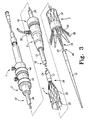
- FIG. 3 is a perspective view of selected segments of another delivery and deployment device including a partially-deployed prosthesis
- FIG. 4 is a cross-sectional view of the device of FIG. 3 around the hemostatic valve assembly
- FIG. 5 is a graph depicting the withdrawal force of various delivery and deployment devices
- FIGS. 6-9 show various features that may be used separately, or in combination, to reduce the sheath withdrawal force of a delivery and deployment device
- FIG. 10 is a graph depicting the sheath withdrawal energy of various delivery and deployment devices.
- FIG. 11 is a graph depicting the average peak deployment force of various delivery and deployment devices.
- distal and distal shall denote a position, direction, or orientation that is generally toward the patient. Accordingly, the terms “proximal” and “proximally” shall denote a position, direction, or orientation that is generally away from the patient.
- FIGS. 1-3 show various exemplary devices 1 for delivering and deploying an expandable endoluminal prosthesis 20 in a body lumen.
- the device 1 includes a prosthesis delivery section 2 and an external manipulation section 3 .
- the delivery section 2 travels through the body lumen during the procedure and delivers the prosthesis to a desired deployment site.
- the external manipulation section 3 stays outside of the body during the procedure.
- the external manipulation section 3 can be manipulated by the operator to position and release or deploy the prosthesis 20 into the body lumen.
- the delivery and deployment device 1 includes a delivery catheter 10 and a sheath 12 .
- the delivery catheter 10 and the sheath 12 are configured to selectively retain and release an expandable prosthesis 20 .
- the delivery catheter 10 has a proximal end and a distal end.
- the distal end of the delivery catheter comprises a dilator head 13 .
- the dilator head 13 is distally tapered to provide for atraumatic insertion into the body lumen (not shown).
- a guidewire lumen 15 extends longitudinally through the delivery catheter 10 between the proximal and distal ends.
- the delivery catheter 10 is configured to receive a guidewire 17 via the guidewire lumen 15 as shown in FIG. 1 .
- the delivery catheter 10 includes a prosthesis receiving portion 16 and a prosthesis release portion 18 , as shown in FIG. 2 .
- the receiving portion 16 is disposed on a distal portion of the delivery catheter 10 and is configured to receive the prosthesis 20 in a radially compressed configuration.
- the receiving portion 16 may include a catheter 22 having a longitudinally uniform external diameter D 1 .
- the release portion 18 of the delivery catheter 10 is disposed generally proximally of the prosthesis 20 .
- the release portion 18 can be manipulated, along with the sheath 12 , to selectively deliver and deploy the prosthesis 20 in the body lumen.
- the release portion 18 may include a dilator catheter 24 having a longitudinally uniform external diameter D 2 .
- Dilator 24 may have a diameter D 2 that is greater than diameter D 1 .
- the release portion 18 includes a distal-facing annular abutment surface 23 at the transition between catheters 22 and 24 .
- the annular abutment surface 23 faces the proximal end of the prosthesis 20 and is configured to contact the proximal end of the prosthesis 20 during deployment, allowing the delivery catheter 10 to push the prosthesis 20 distally as the sheath 12 is pulled proximally in relation thereto.
- the delivery catheter 10 may comprise a single unitary structure as shown in FIG. 2 .
- the delivery catheter 10 may comprise a plurality of slideably interconnected catheters 22 , 24 as shown in FIG. 3 .
- the sheath 12 includes an elongate tubular body having a proximal and distal end and a sheath lumen 14 .
- the sheath lumen 14 has a generally constant diameter between the proximal and distal ends.
- the sheath 12 extends proximally from the delivery section 2 to the user manipulation section 3 .
- the delivery catheter 10 is slideably disposed within lumen 14 .
- the sheath 12 releasably covers and retains the prosthesis 20 in a radially reduced configuration.
- the dilator head 13 and the sheath 20 preferably form a generally smooth transition so as to prevent trauma to the body lumen during delivery and deployment.
- the distal end of the sheath 12 travels within the body lumen during a procedure.
- the proximal end of the sheath 12 is configured to remain outside of the body during the procedure and can be directly manipulated by the operator to deploy the prosthesis 20 .
- the sheath 12 may have a length, as shown in FIG. 3 , that is significantly greater than the length of the prosthesis 20 .
- the sheath 12 may have a length that is two or more times greater than the length of the prosthesis 20 .
- the sheath 12 may have a length that is generally equal to or only somewhat greater than the length of the prosthesis.
- the sheath 12 may have a uniform internal diameter D 3 .
- the internal diameter D 3 is generally equal to the external diameter D 2 of dilator 24 so that the inner surface of the sheath 12 slidingly engages the delivery catheter 10 .
- the sheath may be made of any suitable biocompatible material, for example PTFE, nylon, or polyethylene.
- the sheath may optionally include a flat wire coil (not shown) to provide the sheath with additional flexibility and kink-resistance.
- the prosthesis 20 may include a stent graft having a plurality of self-expanding stents 32 .
- the stents 32 cause the prosthesis 20 to expand during its release from the device 1 .
- the stents 32 may cover and/or may be at least partially covered by a graft material.
- the prosthesis 20 also may include an anchor, such as an exposed stent 34 , for anchoring the prosthesis 20 in the body lumen.
- the stent 34 may be a self-expanding zigzag stent and may comprise barbs 36 , or other anchoring mechanisms, that extend from the stent. When the anchor 34 is released, the barbs 36 , or other anchoring mechanisms, engage the surrounding lumen.
- Suitable graft configurations include, but are not limited to films, coatings, sheets of biocompatible fabrics, non-woven materials and porous materials.
- suitable graft materials include polyesters, such as poly(ethylene terephthalate), polylactide, polyglycolide and copolymers thereof; fluorinated polymers, such as polytetrafluoroethylene (PTFE), expanded PTFE and poly(vinylidene fluoride); polysiloxanes, including polydimethyl siloxane; and polyurethanes, including polyetherurethanes, polyurethane ureas, polyetherurethane ureas, polyurethanes containing carbonate linkages and polyurethanes containing siloxane segments.
- polyesters such as poly(ethylene terephthalate), polylactide, polyglycolide and copolymers thereof
- fluorinated polymers such as polytetrafluoroethylene (PTFE), expanded PTFE and poly(vinylidene fluoride
- Stents may be self-expanding or balloon-expandable.
- a balloon-expandable stent or stent portion may be combined with a self-expanding stent or stent portion.
- Self-expanding stents can be made of stainless steel, materials with elastic memory properties, such as NITINOL, or any other suitable material.
- a suitable self-expanding stent includes Z-STENTS®, which are available from Cook Incorporated, Bloomington, Ind., USA.
- Balloon-expandable stents may be made of various materials including, but not limited to, stainless steel (typically 316LSS, CoCr, Etc.).
- the prosthesis 20 is retained in a radially reduced configuration between the delivery catheter 10 and the sheath 12 .
- the sheath 12 is slideably disposed over the prosthesis 20 and the delivery catheter 10 in a proximal and a distal direction.
- the sheath 12 may be slid proximally with respect to the delivery catheter 10 and the prosthesis 20 to expose the prosthesis.
- the operator slides the sheath 12 proximally while applying distal pressure to the delivery catheter 10 via dilator 24 .
- Dilator 24 pushes the prosthesis 20 distally via the annular abutment surface 23 while the sheath 12 slides proximally in relation thereto.
- dilator 24 pushes the prosthesis 20 distally from the receiving portion 16 and into the body lumen.
- the delivery and deployment device 1 may optionally include deployment control mechanisms 39 , 40 as shown in FIG. 3 .
- Proximal control mechanism 39 releasably retains the proximal end of the prosthesis 20 and distal control mechanism 40 releasably retains the distal end of the prosthesis 20 .
- Proximal control mechanism 39 may include at least one trigger wire 41 (not shown) that releasably couples the proximal end of the prosthesis 20 to the delivery catheter 10 .
- the distal control mechanism 40 may include at least one trigger wire 42 (not shown) that releasably couples the distal end of the prosthesis 20 to the delivery catheter 10 .
- the trigger wires 41 , 42 extend proximally to the external manipulation section 3 where they are coupled to trigger release devices 43 , 44 .
- Trigger release devices 43 , 44 are configured to selectively decouple the proximal and distal ends of the prosthesis from the delivery catheter 10 , respectively.
- Various prosthesis retention devices, configurations, and methods of use are disclosed in PCT Publication No. WO 98/53761, previously incorporated by reference.
- the delivery and deployment device 1 may further include a valve assembly 19 , as shown in FIGS. 3 and 4 .
- the assembly may include a housing 25 and a clamping collar 27 that attaches the housing 25 to the sheath 12 .
- a valve 28 is disposed within the housing 25 between the sheath 12 and the dilator 24 .
- the valve 28 is fixedly connected to the housing 25 and is slideably disposed with respect to the dilator 24 .
- the valve 28 sealingly engages the dilator 24 to control blood loss between the delivery catheter 10 and the sheath 12 .
- the hemostatic sealing device 19 may also include a side tube 30 that facilitates the introduction of medical reagents between the delivery catheter 10 and the sheath 12 .
- the valve may include, for example, one or more check valves and/or one or more “iris”-type valves.
- Suitable check valves include CHECK-FLO® valves.
- Suitable valve assemblies include the CAPTOR® Hemostatic Valve. Each are available from Cook Incorporated, Bloomington, Ind., USA. Other suitable valves and valve assemblies are described in the patent literature, for example, in U.S. Pat. No. 4,430,081, entitled “Hemostasis Sheath,” U.S. Pat. No. 5,006,113, entitled “Hemostasis Cannula,” U.S. Pat. No. 5,267,966, entitled “Hemostasis Cannula and Method of Making a Valve for Same,” U.S. Pat. No.
- a primary function of the valve assembly 19 is controlling and limiting blood loss during a procedure.
- the valve 28 preferably forms a tight sealing engagement with the dilator 24 .
- a tight seal may be provided, for example, by maximizing the area of surface contact between the valve 28 and the dilator 24 and by maximizing the pressure asserted by the valve against the dilator.
- the friction between the sheath 12 and the delivery catheter 10 may increase, thereby increasing the force required to slide the valve assembly 19 , and therefore the sheath 12 , over the delivery catheter 10 .
- This “valve” resistance may constitute a significant component of the sheath withdrawal force.
- a lubricant was applied to the dilator within the valve housing.
- a lubricant was applied to the dilator, outside of the housing, to lubricate the region that would be traversed by the valve during sheath withdrawal.
- FIG. 5 shows a graph of the sheath withdrawal force as a function of time (which is proportional to sheath withdrawal distance).
- Curve A depicts the results of an experiment where the housing of the device was irrigated with a saline solution. In this experiment, the peak withdrawal force was greater than 50 Newtons.
- Curve B depicts the result of another experiment where the valve and dilator were irrigated with a saline solution, outside of the valve housing, to lubricate the region that would be traversed by the valve. In this experiment, the peak withdrawal force was less than 40 Newtons.
- Other lubricants were tested, including hyaluronic acid, polyvinylpyrolidone, Liposyn® III, and olive oil.
- the inventors theorized that the static friction force could be substantially reduced by lubricating the contact surface between the valve and the dilator, immediately prior to withdrawing the sheath over the dilator.
- adequate lubrication of this contact surface was difficult due to the tight seal and static bond between the valve and dilator. Accordingly, the inventors developed novel valve lubrication mechanisms and methods for lubricating this contact surface.
- a lubrication mechanism may be provided that is slideably disposed between the valve and the dilator.
- the mechanism has an inner surface in sliding contact with the outer surface of the dilator and an outer surface in sliding contact with the valve.
- the lubrication mechanism is adapted to receive a lubricant.
- the physician may slide the lubrication mechanism along the dilator, and through the valve, so that lubricant that is present on the lubrication mechanism may traverse and lubricate the valve and the dilator-valve contact surface.
- a solid lubricant such as a dried or evaporated lubricant coating
- a liquid lubricant such as saline solution
- suitable lubricants include, for example, saline solutions, hyaluronic acid, polyvinylpyrolidone, polyacrylamide, silicones, lipid emulsions such as Liposyn® (available from Abbott Laboratories) and RotaglideTM (available from Boston Scientific), and the like.
- FIG. 6 illustrates a delivery and deployment device 101 that is similar to the devices shown in FIGS. 1-4 and described above.
- the device comprises a sheath 112 and a dilator 124 slidingly disposed within a lumen of the sheath 112 .
- a valve assembly 119 is attached to the sheath 112 and comprises a housing 125 and a valve 128 disposed within the housing 125 between the sheath 112 and the dilator 124 .
- the device 101 further comprises a sleeve 150 that is slidingly disposed about the dilator 124 . As shown in FIG. 6 , the sleeve 150 may be positioned so that its outer surface is in sliding contact with the valve 128 .
- FIG. 6 illustrates a delivery and deployment device 101 that is similar to the devices shown in FIGS. 1-4 and described above.
- the device comprises a sheath 112 and a dilator 124 slidingly disposed within a lumen of the sheath 11
- the distal end of the sleeve 150 is disposed within the housing 125 , distal to the valve 128 , and the proximal end of the sleeve 150 is disposed outside of the housing 125 , proximal to the valve 128 .
- the sleeve preferably comprises a handle, or the like, to manipulate and slide the sleeve along the dilator and through the valve assembly.
- the sleeve 150 may comprise a peel-away sleeve such as the PEEL-AWAY® sheath, which is available from Cook Incorporated, Bloomington, Ind., USA.
- a delivery and deployment device that utilizes a peel-away sleeve is the H&L-B ONE-SHOTTM Introduction System, which is also available from Cook Incorporated.
- Such a sleeve typically has a smooth and lubricious surface, for example, to allow the sleeve to slide easily between the dilator and valve and is provided, for example, to shield and protect the valve during loading of the dilator into the sheath.
- the sleeve is typically provided with the delivery and deployment device and is removed prior to use of the device.
- the sleeve 150 may be provided with one or more grooves 152 , or the like, formed on an outside surface of the sleeve 150 .
- the grooves 152 allow the sheath to receive and retain a lubricant.
- the valve 128 traverses the sleeve surface and the grooves 152 .
- Lubricant that is present in the grooves 152 traverses, or passes under, the valve 128 and lubricates the valve surface.
- the grooves 152 may be disposed circumferentially and/or longitudinally along the sleeve 150 . For example, in FIG.
- the sleeve 150 includes a plurality of annular grooves 152 and in FIG. 8 the sleeve 150 includes one or more helical grooves 152 .
- a sleeve 150 may be provided and include grooves, such as the grooves 162 , 166 , illustrated in FIG. 9 .
- the term “groove” refers to a channel, depression, cut, score, notch, line, perforation, aperture, or the like, and includes both recessed structures as well as projected structures.
- the term “groove” may also refer to a series of channels, depressions, cuts, scores, notches, lines, perforations, apertures, or the like.
- a groove may be provided by any mechanical, thermal, or chemical means known in the art, such as cutting by knife or carbide tip, by sanding, by chemical etching, by laser scoring, or by molding.
- the dilator 124 may additionally, or alternatively, include one or more grooves 160 formed on an outside surface of the dilator.
- the grooves 160 may be disposed circumferentially and/or longitudinally along the dilator 124 .
- the dilator 124 has a plurality of substantially longitudinal grooves 162 and a roughened region 164 that includes a plurality of short grooves 166 that provide a roughened or textured surface.
- the grooves 162 , 166 may be provided, for example, to increase the surface area of the dilator 124 and to improve wetting and retention of lubricants.
- the sleeve 150 and/or the dilator 124 may comprise a lubricant coating.
- the lubricant may be a liquid lubricant or a solid lubricant and may be applied to a surface by any suitable process, such as dipping or spraying. After the lubricant is applied, it can be cured to form a coating.
- a 1% aqueous hyaluronic acid solution may be applied to a surface and cured by drying the solution to remove some or substantially all of the water.
- photo polyvinylpyrolidone may be applied to the dilator and cured by exposing the surface to an ultraviolet light source.
- the mechanism 101 included a peel-away sleeve 150 with circumferential grooves 152 , as described above.
- the dilator 124 included a plurality of longitudinal grooves 162 , and a roughened surface 164 , similar to the configuration shown in FIG. 9 .
- the inventors applied an aqueous solution of hyaluronic acid to the grooved surface of the dilator 124 .
- the solution was prepared by diluting 1 part granular hyaluronic acid in 400 parts water.
- a saline solution was introduced into the valve housing 125 via the side tube 130 .
- the sleeve 150 was then removed from the valve housing 125 by sliding the distal end of the sleeve 150 along the dilator 124 , past the valve 128 .
- Saline solution that was present in the circumferential grooves 152 was pulled through the valve, thus wetting the valve surface.
- Saline solution also traveled along the grooves 162 and roughened surface 164 of the dilator 124 , thus wetting the lubricant coating.
- the hydrated coating became slippery and reduced the static friction between the dilator 124 and the valve 128 .
- Curve C of FIG. 5 depicts the exceptional results of this experiment, where the peak withdrawal force was approximately 5 Newtons and the withdrawal force was generally consistent. This device and method resulted, surprisingly, in a 95% reduction in the peak withdrawal force compared to the experiment described above and depicted in curve A.
- the inventors studied the effect of the valve lubrication mechanism on the Zenith® delivery and deployment system.
- the Zenith® systems are available from Cook Incorporated, Bloomington, Ind., USA.
- the delivery and deployment device used in the study included a hemostatic valve assembly with three silicone valves.
- the prosthesis was removed from the delivery and deployment device to enable the inventors to measure only the frictional force between the dilator and the silicone valves.
- control devices included a standard delivery and deployment device, without modification.
- the “water,” “PVP,” and “HLA” devices were modified by roughening the outer surface of the PEEL-AWAY® sheath and the outer surface of the dilator.
- the inventors used sandpaper to apply circumferential grooves to a 0.5 inch length portion of the outer surface of the PEEL-AWAY® sheath, and to apply longitudinal grooves to a 2 inch portion of the dilator.
- the grooved PEEL-AWAY® sheath was cleaned with a cotton-tipped swab wetted with ethyl alcohol and the grooved dilator was cleaned with a cotton-tipped swab wetted with water.
- a 1% HLA/water solution was applied to the grooved dilator surface of the “HLA” devices.
- the HLA was Sigma 53747-10G, available from Sigma-Aldrich®, St. Louis, Mo., USA.
- the application was dried in air until it was no longer tacky.
- a PVP polymer solution was applied to the grooved dilator surface of the “PVP” devices.
- the PVP was 2002-HC, available from Cook, Incorporated, Bloomington, Ind., USA.
- the application was cured with ultraviolet light until it was no longer tacky.
- the dilators were positioned so that the distal edge of the coating was disposed distal of the silicone valves.
- the PEEL-AWAY® sheaths were positioned so that the distal edge of the sheath was disposed distal of the silicone valves.
- Tests were performed on delivery and deployment devices with 14 F, 16 F, and 8 F diameter dilators.
- the delivery and deployment devices were mounted vertically in a test fixture attached to the base of an Instron machine (available from Instron Corporation, Norwood, Mass., USA).
- the control devices were prepared by removing the PEEL-AWAY® sheaths and then filling the valve housings with water, consistent with the Instructions for Use for the delivery and deployment device.
- the “water,” “PVP,” and “HLA” devices were prepared by filling the valve housings before the PEEL-AWAY® sheaths were removed. The sheaths were then removed to lubricate the silicone valves and the dilator. Then, the valve housings were again filled with water.
- FIG. 10 is a bar chart that depicts the sheath withdrawal energy (N-cm), or the average withdrawal force multiplied by retraction distance.
- N-cm sheath withdrawal energy
- the lubrication mechanisms resulted in an overall reduction of the energy required to withdraw the sheath, compared to devices that did not include a lubrication mechanism.
- the improvements ranged from an approximately 20% reduction in energy for the 14 FR “water” device to an approximately 80% reduction for the 18 FR “HLA” device.
- FIG. 11 is a bar chart that depicts the average peak deployment force (N) for the various devices.
- N the average peak deployment force
- the lubrication mechanisms resulted in an overall reduction of the peak force, compared to devices that did not include a lubrication mechanism.
- the improvements ranged from an approximately 13% reduction for the 14 FR “water” device to an approximately 70% reduction for the 18 FR “HLA” device.
- the withdrawal energy and the average peak deployment force increased as the size of the dilator increased.
- the results indicate that dilator size was less significant a factor.
- one of the challenges with using lubricants is that the device may become slippery and difficult to grasp and manipulate. Accordingly, it may be desirable to control the ability of the lubricant to travel along the dilator 124 , outside of the housing 125 . Therefore, in some examples, the length of the roughened region 164 and the length and extent of the grooves 162 , and other aspects of the design may be controlled to limit or prevent lubricant from traveling too far beyond the housing 125 . In other examples, the dilator and/or sleeve may be provided without grooves.
Abstract
Description
Claims (22)
Priority Applications (1)
| Application Number | Priority Date | Filing Date | Title |
|---|---|---|---|
| US12/330,833 US8858608B2 (en) | 2007-12-10 | 2008-12-09 | Lubrication apparatus for a delivery and deployment device |
Applications Claiming Priority (2)
| Application Number | Priority Date | Filing Date | Title |
|---|---|---|---|
| US1255007P | 2007-12-10 | 2007-12-10 | |
| US12/330,833 US8858608B2 (en) | 2007-12-10 | 2008-12-09 | Lubrication apparatus for a delivery and deployment device |
Publications (2)
| Publication Number | Publication Date |
|---|---|
| US20090149938A1 US20090149938A1 (en) | 2009-06-11 |
| US8858608B2 true US8858608B2 (en) | 2014-10-14 |
Family
ID=40722431
Family Applications (1)
| Application Number | Title | Priority Date | Filing Date |
|---|---|---|---|
| US12/330,833 Active 2033-03-16 US8858608B2 (en) | 2007-12-10 | 2008-12-09 | Lubrication apparatus for a delivery and deployment device |
Country Status (1)
| Country | Link |
|---|---|
| US (1) | US8858608B2 (en) |
Families Citing this family (5)
| Publication number | Priority date | Publication date | Assignee | Title |
|---|---|---|---|---|
| JP5181211B2 (en) * | 2005-12-23 | 2013-04-10 | クック・メディカル・テクノロジーズ・リミテッド・ライアビリティ・カンパニー | Trigger wire release mechanism and introducer for prosthesis including the same |
| AU2011272764B2 (en) * | 2010-06-30 | 2015-11-19 | Muffin Incorporated | Percutaneous, ultrasound-guided introduction of medical devices |
| US8419783B2 (en) * | 2010-07-07 | 2013-04-16 | Cook Medical Technologies Llc | Graft deployment assist tool |
| WO2014071014A1 (en) | 2012-11-01 | 2014-05-08 | Muffin Incorporated | Implements for identifying sheath migration |
| US10238495B2 (en) * | 2015-10-09 | 2019-03-26 | Evalve, Inc. | Delivery catheter handle and methods of use |
Citations (99)
| Publication number | Priority date | Publication date | Assignee | Title |
|---|---|---|---|---|
| US2321336A (en) | 1942-08-10 | 1943-06-08 | Albert W Tondreau | Valve |
| US2416391A (en) | 1945-08-18 | 1947-02-25 | Wyeth Corp | Fluid transfer apparatus |
| US2844351A (en) | 1953-04-17 | 1958-07-22 | Baxter Don Inc | Fluid flow control |
| US3185179A (en) | 1961-05-05 | 1965-05-25 | Pharmaseal Lab | Disposable valve |
| US3304934A (en) | 1964-09-29 | 1967-02-21 | Dionisio O Bautista | Blood drawing device |
| US3329390A (en) | 1965-02-18 | 1967-07-04 | Eldon E Hulsey | Variable orifice valve |
| US3599637A (en) | 1969-05-12 | 1971-08-17 | Boris Schwartz | Intravenous catheter assembly |
| US4000739A (en) | 1975-07-09 | 1977-01-04 | Cordis Corporation | Hemostasis cannula |
| US4016879A (en) | 1973-08-22 | 1977-04-12 | Dynasciences Corporation | Multi-mode cannulating apparatus |
| US4063555A (en) | 1975-01-24 | 1977-12-20 | Aktiebolaget Stille-Werner | Cannula assembly |
| US4243034A (en) | 1978-10-17 | 1981-01-06 | Viggo Ab | Cannula or catheter assembly |
| US4311137A (en) | 1980-04-30 | 1982-01-19 | Sherwood Medical Industries Inc. | Infusion device |
| US4314555A (en) | 1979-02-20 | 1982-02-09 | Terumo Corporation | Intravascular catheter assembly |
| US4424833A (en) | 1981-10-02 | 1984-01-10 | C. R. Bard, Inc. | Self sealing gasket assembly |
| US4430081A (en) | 1981-01-06 | 1984-02-07 | Cook, Inc. | Hemostasis sheath |
| US4540411A (en) | 1983-11-28 | 1985-09-10 | Sherwood Medical Company | Catheter placement device |
| US4580573A (en) | 1983-10-20 | 1986-04-08 | Medical Device Development Corporation, Inc. | Catheter introducer |
| US4610674A (en) | 1984-09-13 | 1986-09-09 | Terumo Kabushi Kaisha | Catheter introducing instrument |
| US4610665A (en) | 1983-01-18 | 1986-09-09 | Terumo Kabushiki Kaisha | Medical instrument |
| US4626245A (en) | 1985-08-30 | 1986-12-02 | Cordis Corporation | Hemostatis valve comprising an elastomeric partition having opposed intersecting slits |
| US4629450A (en) | 1984-05-09 | 1986-12-16 | Terumo Corporation | Catheter introducing instrument |
| US4798594A (en) | 1987-09-21 | 1989-01-17 | Cordis Corporation | Medical instrument valve |
| EP0344907A2 (en) | 1988-06-02 | 1989-12-06 | C.R. Bard, Inc. | Self-sealing guidewire and catheter introducer |
| US4895565A (en) | 1987-09-21 | 1990-01-23 | Cordis Corporation | Medical instrument valve |
| US4929235A (en) | 1985-07-31 | 1990-05-29 | Universal Medical Instrument Corp. | Self-sealing percutaneous tube introducer |
| US4932633A (en) | 1988-11-21 | 1990-06-12 | Schneider-Shiley (U.S.A.) Inc. | Hemostasis valve |
| US4978341A (en) | 1988-04-07 | 1990-12-18 | Schneider Europe | Introducer valve for a catheter arrangement |
| US5000745A (en) | 1988-11-18 | 1991-03-19 | Edward Weck Incorporated | Hemostatis valve |
| US5006113A (en) | 1990-02-08 | 1991-04-09 | Cook Incorporated | Hemostasis cannula |
| US5009391A (en) | 1988-05-02 | 1991-04-23 | The Kendall Company | Valve assembly |
| US5053013A (en) | 1990-03-01 | 1991-10-01 | The Regents Of The University Of Michigan | Implantable infusion device |
| US5066285A (en) | 1990-01-26 | 1991-11-19 | Cordis Corporation | Catheter introducer sheath made of expanded polytetrafluoroethylene |
| US5098393A (en) | 1988-05-31 | 1992-03-24 | Kurt Amplatz | Medical introducer and valve assembly |
| US5102395A (en) | 1991-06-26 | 1992-04-07 | Adam Spence Corporation | Hemostasis valve |
| US5125903A (en) | 1991-08-01 | 1992-06-30 | Medtronic, Inc. | Hemostasis valve |
| US5154701A (en) | 1991-06-26 | 1992-10-13 | Adam Spence Corporation | Hemostasis valve |
| US5158553A (en) | 1990-12-26 | 1992-10-27 | Cardiopulmonics | Rotatably actuated constricting catheter valve |
| US5167637A (en) | 1990-11-01 | 1992-12-01 | Sherwood Medical Company | Valve membrane for a catheter introducer hemostatic valve |
| US5176652A (en) | 1989-12-22 | 1993-01-05 | Cordis Corporation | Hemostasis valve |
| US5211370A (en) | 1992-01-06 | 1993-05-18 | Powers Ronald J | Variable orifice sealing valve |
| US5222970A (en) * | 1991-09-06 | 1993-06-29 | William A. Cook Australia Pty. Ltd. | Method of and system for mounting a vascular occlusion balloon on a delivery catheter |
| EP0550069A1 (en) | 1992-01-03 | 1993-07-07 | United States Surgical Corporation | Variable interior dimension cannula assembly |
| US5242413A (en) | 1991-08-21 | 1993-09-07 | Vygon Gmbh & Co. Kg | Disc valve for a catheter |
| US5256150A (en) | 1991-12-13 | 1993-10-26 | Endovascular Technologies, Inc. | Large-diameter expandable sheath and method |
| US5267966A (en) | 1992-09-28 | 1993-12-07 | Cook Incorporated | Hemostasis cannula and method of making a valve for same |
| US5300032A (en) | 1988-09-15 | 1994-04-05 | Mallinckrodt Medical, Inc. | Catheter introducer with flexible tip |
| US5304156A (en) | 1988-06-02 | 1994-04-19 | C. R. Bard, Inc. | Self-sealing guidewire and catheter introducer |
| US5350363A (en) | 1993-06-14 | 1994-09-27 | Cordis Corporation | Enhanced sheath valve |
| US5350364A (en) | 1991-10-18 | 1994-09-27 | Ethicon, Inc. | Universal seal for trocar assembly |
| US5376077A (en) | 1992-12-04 | 1994-12-27 | Interventional Technologies, Inc. | Introducer sheath with seal protector |
| US5395349A (en) | 1991-12-13 | 1995-03-07 | Endovascular Technologies, Inc. | Dual valve reinforced sheath and method |
| US5395352A (en) | 1992-02-24 | 1995-03-07 | Scimed Lift Systems, Inc. | Y-adaptor manifold with pinch valve for an intravascular catheter |
| US5409463A (en) | 1992-06-05 | 1995-04-25 | Thomas Medical Products, Inc. | Catheter introducer with lubrication means |
| US5538505A (en) | 1993-06-14 | 1996-07-23 | Cordis Corporation | Hemostasis valve for catheter introducer having thickened central partition section |
| EP0755694A1 (en) | 1995-07-27 | 1997-01-29 | Cordis Corporation | Guiding catheter introducer assembly |
| US5613956A (en) | 1993-05-07 | 1997-03-25 | C. R. Bard, Inc. | Catheter introducer |
| US5643227A (en) | 1995-01-19 | 1997-07-01 | Stevens; Robert C. | Hemostasis cannula valve apparatus and method of using same |
| US5779681A (en) | 1991-12-16 | 1998-07-14 | Thomas Jefferson University | Vascular access sheath for interventional devices |
| WO1998053761A1 (en) | 1997-05-26 | 1998-12-03 | William A. Cook Australia Pty. Ltd. | A prosthesis and a method and means of deploying a prosthesis |
| US5895376A (en) | 1996-10-23 | 1999-04-20 | Mayo Foundation For Medical Education And Research | Hemostasis valve, system and assembly |
| WO1999026682A1 (en) | 1997-09-26 | 1999-06-03 | Cordis Corporation | Intravascular catheter system with convertible sheath extension for magnetic resonance imaging and method |
| US5935122A (en) | 1991-12-13 | 1999-08-10 | Endovascular Technologies, Inc. | Dual valve, flexible expandable sheath and method |
| US6042588A (en) | 1998-03-03 | 2000-03-28 | Scimed Life Systems, Inc | Stent delivery system |
| US6054421A (en) | 1997-09-23 | 2000-04-25 | Scimed Life Systems, Inc. | Medical emulsion lubricant |
| US6086570A (en) | 1998-09-29 | 2000-07-11 | A-Med Systems, Inc. | Hemostasis valve with membranes having offset apertures |
| US6127320A (en) | 1998-01-19 | 2000-10-03 | University Of Cincinnati | Methods and compositions for increasing lubricity of rubber surfaces |
| US6179863B1 (en) | 1991-11-08 | 2001-01-30 | Kensey Nash Corporation | Hemostatic puncture closure system and method of use |
| US6276661B1 (en) | 1996-11-06 | 2001-08-21 | Medtronic, Inc. | Pressure actuated introducer valve |
| US6379372B1 (en) | 1996-09-12 | 2002-04-30 | Edwards Lifesciences Corp. | Endovascular delivery system |
| US6416499B2 (en) | 1997-07-30 | 2002-07-09 | Cook Incorporated | Medical fluid flow control valve |
| US20030018306A1 (en) * | 2001-07-23 | 2003-01-23 | Weenna Bucay-Couto | Long-term indwelling medical devices containing slow-releasing antimicrobial agents and having a surfactant surface |
| US6562049B1 (en) | 2000-03-01 | 2003-05-13 | Cook Vascular Incorporated | Medical introducer apparatus |
| US20030144670A1 (en) | 2001-11-29 | 2003-07-31 | Cook Incorporated | Medical device delivery system |
| US6610031B1 (en) | 2001-04-18 | 2003-08-26 | Origin Medsystems, Inc. | Valve assembly |
| US20030216771A1 (en) | 2002-03-15 | 2003-11-20 | Thomas P. Osypka | Locking vascular introducer assembly with adjustable hemostatic seal |
| US6652480B1 (en) | 1997-03-06 | 2003-11-25 | Medtronic Ave., Inc. | Methods for reducing distal embolization |
| US6663599B2 (en) | 1992-05-06 | 2003-12-16 | Cook Incorporated | Hemostasis cannula |
| EP1374942A1 (en) | 2002-06-26 | 2004-01-02 | Medikit Co., Ltd. | Indwelling catheter set |
| US6740101B2 (en) | 1998-06-10 | 2004-05-25 | Converge Medical, Inc. | Sutureless anastomosis systems |
| US20040176781A1 (en) | 2003-03-06 | 2004-09-09 | Cardiac Pacemakers, Inc. | Lead insertion tool for hemostatic introducer system |
| US20050060018A1 (en) | 2003-09-16 | 2005-03-17 | Cook Incorporated | Prosthesis deployment system |
| US20050085890A1 (en) | 2003-10-15 | 2005-04-21 | Cook Incorporated | Prosthesis deployment system retention device |
| US20050096605A1 (en) | 1992-04-24 | 2005-05-05 | Green David T. | Valve assembly for introducing instruments into body cavities |
| US20050171479A1 (en) | 2003-12-11 | 2005-08-04 | Hruska Christopher L. | Hemostatic valve assembly |
| US20050171470A1 (en) * | 2004-01-29 | 2005-08-04 | Cannuflow Incorporated | Atraumatic arthroscopic instrument sheath |
| US6966896B2 (en) | 2002-09-04 | 2005-11-22 | Paul A. Kurth | Introducer and hemostatic valve combination and method of using the same |
| US6981966B2 (en) | 1991-10-18 | 2006-01-03 | United States Surgical | Valve assembly for introducing instruments into body cavities |
| US20060052750A1 (en) | 2004-09-09 | 2006-03-09 | Jay Lenker | Expandable transluminal sheath |
| US20060282155A1 (en) * | 2005-05-10 | 2006-12-14 | William A. Cook Australia Pty Ltd. | Laparoscopic vascular access |
| US20070026038A1 (en) | 2002-05-24 | 2007-02-01 | Biotronik Mess- Und Therapiegeraete Gmbh & Co. | Method of Coating a Stent with a Polysaccharide Layer and Associated Stents |
| US7182771B1 (en) | 2001-12-20 | 2007-02-27 | Russell A. Houser | Vascular couplers, techniques, methods, and accessories |
| US20070088420A1 (en) | 2003-06-09 | 2007-04-19 | Xtent, Inc. | Stent deployment systems and methods |
| US7226433B2 (en) | 1998-02-06 | 2007-06-05 | Possis Medical, Inc. | Thrombectomy catheter device having a self-sealing hemostasis valve |
| US7241276B2 (en) | 2003-08-06 | 2007-07-10 | Trivascular, Inc. | Passive hemostatic sheath valve |
| US20070185558A1 (en) * | 2006-01-18 | 2007-08-09 | William A. Cook Australia Pty. Ltd. | Endoluminal delivery device |
| US20070299518A1 (en) | 2006-01-27 | 2007-12-27 | Med Institute, Inc. | Device with nanocomposite coating for controlled drug release |
| US7351247B2 (en) | 2002-09-04 | 2008-04-01 | Bioconnect Systems, Inc. | Devices and methods for interconnecting body conduits |
| US20080294096A1 (en) | 2005-11-04 | 2008-11-27 | Medrad Inc. | Delivery of Agents Such as Cells to Tissue |
| US20090099636A1 (en) * | 2007-10-10 | 2009-04-16 | C.R. Bard, Inc. | Low friction vascular implant delivery device |
-
2008
- 2008-12-09 US US12/330,833 patent/US8858608B2/en active Active
Patent Citations (107)
| Publication number | Priority date | Publication date | Assignee | Title |
|---|---|---|---|---|
| US2321336A (en) | 1942-08-10 | 1943-06-08 | Albert W Tondreau | Valve |
| US2416391A (en) | 1945-08-18 | 1947-02-25 | Wyeth Corp | Fluid transfer apparatus |
| US2844351A (en) | 1953-04-17 | 1958-07-22 | Baxter Don Inc | Fluid flow control |
| US3185179A (en) | 1961-05-05 | 1965-05-25 | Pharmaseal Lab | Disposable valve |
| US3304934A (en) | 1964-09-29 | 1967-02-21 | Dionisio O Bautista | Blood drawing device |
| US3329390A (en) | 1965-02-18 | 1967-07-04 | Eldon E Hulsey | Variable orifice valve |
| US3599637A (en) | 1969-05-12 | 1971-08-17 | Boris Schwartz | Intravenous catheter assembly |
| US4016879A (en) | 1973-08-22 | 1977-04-12 | Dynasciences Corporation | Multi-mode cannulating apparatus |
| US4063555A (en) | 1975-01-24 | 1977-12-20 | Aktiebolaget Stille-Werner | Cannula assembly |
| US4000739A (en) | 1975-07-09 | 1977-01-04 | Cordis Corporation | Hemostasis cannula |
| US4243034A (en) | 1978-10-17 | 1981-01-06 | Viggo Ab | Cannula or catheter assembly |
| US4314555A (en) | 1979-02-20 | 1982-02-09 | Terumo Corporation | Intravascular catheter assembly |
| US4311137A (en) | 1980-04-30 | 1982-01-19 | Sherwood Medical Industries Inc. | Infusion device |
| US4430081A (en) | 1981-01-06 | 1984-02-07 | Cook, Inc. | Hemostasis sheath |
| US4424833A (en) | 1981-10-02 | 1984-01-10 | C. R. Bard, Inc. | Self sealing gasket assembly |
| US4610665A (en) | 1983-01-18 | 1986-09-09 | Terumo Kabushiki Kaisha | Medical instrument |
| US4580573A (en) | 1983-10-20 | 1986-04-08 | Medical Device Development Corporation, Inc. | Catheter introducer |
| US4540411A (en) | 1983-11-28 | 1985-09-10 | Sherwood Medical Company | Catheter placement device |
| US4629450A (en) | 1984-05-09 | 1986-12-16 | Terumo Corporation | Catheter introducing instrument |
| US4610674A (en) | 1984-09-13 | 1986-09-09 | Terumo Kabushi Kaisha | Catheter introducing instrument |
| US4929235A (en) | 1985-07-31 | 1990-05-29 | Universal Medical Instrument Corp. | Self-sealing percutaneous tube introducer |
| US4626245A (en) | 1985-08-30 | 1986-12-02 | Cordis Corporation | Hemostatis valve comprising an elastomeric partition having opposed intersecting slits |
| US4798594A (en) | 1987-09-21 | 1989-01-17 | Cordis Corporation | Medical instrument valve |
| US4895565A (en) | 1987-09-21 | 1990-01-23 | Cordis Corporation | Medical instrument valve |
| US4978341A (en) | 1988-04-07 | 1990-12-18 | Schneider Europe | Introducer valve for a catheter arrangement |
| US5009391A (en) | 1988-05-02 | 1991-04-23 | The Kendall Company | Valve assembly |
| US5098393A (en) | 1988-05-31 | 1992-03-24 | Kurt Amplatz | Medical introducer and valve assembly |
| US5702370A (en) | 1988-06-02 | 1997-12-30 | C. R. Bard, Inc. | Self-sealing guidewire and catheter introducer |
| EP0344907A2 (en) | 1988-06-02 | 1989-12-06 | C.R. Bard, Inc. | Self-sealing guidewire and catheter introducer |
| US5304156A (en) | 1988-06-02 | 1994-04-19 | C. R. Bard, Inc. | Self-sealing guidewire and catheter introducer |
| US5300032A (en) | 1988-09-15 | 1994-04-05 | Mallinckrodt Medical, Inc. | Catheter introducer with flexible tip |
| US5000745A (en) | 1988-11-18 | 1991-03-19 | Edward Weck Incorporated | Hemostatis valve |
| US4932633A (en) | 1988-11-21 | 1990-06-12 | Schneider-Shiley (U.S.A.) Inc. | Hemostasis valve |
| US5176652A (en) | 1989-12-22 | 1993-01-05 | Cordis Corporation | Hemostasis valve |
| US5066285A (en) | 1990-01-26 | 1991-11-19 | Cordis Corporation | Catheter introducer sheath made of expanded polytetrafluoroethylene |
| US5006113A (en) | 1990-02-08 | 1991-04-09 | Cook Incorporated | Hemostasis cannula |
| US5053013A (en) | 1990-03-01 | 1991-10-01 | The Regents Of The University Of Michigan | Implantable infusion device |
| US5167637A (en) | 1990-11-01 | 1992-12-01 | Sherwood Medical Company | Valve membrane for a catheter introducer hemostatic valve |
| US5158553A (en) | 1990-12-26 | 1992-10-27 | Cardiopulmonics | Rotatably actuated constricting catheter valve |
| US5102395A (en) | 1991-06-26 | 1992-04-07 | Adam Spence Corporation | Hemostasis valve |
| US5154701A (en) | 1991-06-26 | 1992-10-13 | Adam Spence Corporation | Hemostasis valve |
| US5125903A (en) | 1991-08-01 | 1992-06-30 | Medtronic, Inc. | Hemostasis valve |
| US5242413A (en) | 1991-08-21 | 1993-09-07 | Vygon Gmbh & Co. Kg | Disc valve for a catheter |
| US5222970A (en) * | 1991-09-06 | 1993-06-29 | William A. Cook Australia Pty. Ltd. | Method of and system for mounting a vascular occlusion balloon on a delivery catheter |
| US6981966B2 (en) | 1991-10-18 | 2006-01-03 | United States Surgical | Valve assembly for introducing instruments into body cavities |
| US5350364A (en) | 1991-10-18 | 1994-09-27 | Ethicon, Inc. | Universal seal for trocar assembly |
| US6179863B1 (en) | 1991-11-08 | 2001-01-30 | Kensey Nash Corporation | Hemostatic puncture closure system and method of use |
| US5256150A (en) | 1991-12-13 | 1993-10-26 | Endovascular Technologies, Inc. | Large-diameter expandable sheath and method |
| US6197016B1 (en) | 1991-12-13 | 2001-03-06 | Endovascular Technologies, Inc. | Dual valve, flexible expandable sheath and method |
| US5395349A (en) | 1991-12-13 | 1995-03-07 | Endovascular Technologies, Inc. | Dual valve reinforced sheath and method |
| US5653697A (en) | 1991-12-13 | 1997-08-05 | Endovascular Technologies, Inc. | Dual valve reinforced sheath and method |
| US5935122A (en) | 1991-12-13 | 1999-08-10 | Endovascular Technologies, Inc. | Dual valve, flexible expandable sheath and method |
| US5484418A (en) | 1991-12-13 | 1996-01-16 | Endovascular Technologies, Inc. | Dual valve reinforced sheath and method |
| US5779681A (en) | 1991-12-16 | 1998-07-14 | Thomas Jefferson University | Vascular access sheath for interventional devices |
| EP0550069A1 (en) | 1992-01-03 | 1993-07-07 | United States Surgical Corporation | Variable interior dimension cannula assembly |
| US5211370A (en) | 1992-01-06 | 1993-05-18 | Powers Ronald J | Variable orifice sealing valve |
| US5395352A (en) | 1992-02-24 | 1995-03-07 | Scimed Lift Systems, Inc. | Y-adaptor manifold with pinch valve for an intravascular catheter |
| US20050096605A1 (en) | 1992-04-24 | 2005-05-05 | Green David T. | Valve assembly for introducing instruments into body cavities |
| US6663599B2 (en) | 1992-05-06 | 2003-12-16 | Cook Incorporated | Hemostasis cannula |
| US5409463A (en) | 1992-06-05 | 1995-04-25 | Thomas Medical Products, Inc. | Catheter introducer with lubrication means |
| US5267966A (en) | 1992-09-28 | 1993-12-07 | Cook Incorporated | Hemostasis cannula and method of making a valve for same |
| US5376077A (en) | 1992-12-04 | 1994-12-27 | Interventional Technologies, Inc. | Introducer sheath with seal protector |
| US5613956A (en) | 1993-05-07 | 1997-03-25 | C. R. Bard, Inc. | Catheter introducer |
| US5538505A (en) | 1993-06-14 | 1996-07-23 | Cordis Corporation | Hemostasis valve for catheter introducer having thickened central partition section |
| US5350363A (en) | 1993-06-14 | 1994-09-27 | Cordis Corporation | Enhanced sheath valve |
| US5643227A (en) | 1995-01-19 | 1997-07-01 | Stevens; Robert C. | Hemostasis cannula valve apparatus and method of using same |
| EP0755694A1 (en) | 1995-07-27 | 1997-01-29 | Cordis Corporation | Guiding catheter introducer assembly |
| US6379372B1 (en) | 1996-09-12 | 2002-04-30 | Edwards Lifesciences Corp. | Endovascular delivery system |
| US5895376A (en) | 1996-10-23 | 1999-04-20 | Mayo Foundation For Medical Education And Research | Hemostasis valve, system and assembly |
| US6221057B1 (en) | 1996-10-23 | 2001-04-24 | Mayo Foundation For Medical Education And Research | Hemostasis valve, system and assembly |
| US6276661B1 (en) | 1996-11-06 | 2001-08-21 | Medtronic, Inc. | Pressure actuated introducer valve |
| US6652480B1 (en) | 1997-03-06 | 2003-11-25 | Medtronic Ave., Inc. | Methods for reducing distal embolization |
| WO1998053761A1 (en) | 1997-05-26 | 1998-12-03 | William A. Cook Australia Pty. Ltd. | A prosthesis and a method and means of deploying a prosthesis |
| US6416499B2 (en) | 1997-07-30 | 2002-07-09 | Cook Incorporated | Medical fluid flow control valve |
| US6054421A (en) | 1997-09-23 | 2000-04-25 | Scimed Life Systems, Inc. | Medical emulsion lubricant |
| WO1999026682A1 (en) | 1997-09-26 | 1999-06-03 | Cordis Corporation | Intravascular catheter system with convertible sheath extension for magnetic resonance imaging and method |
| US6127320A (en) | 1998-01-19 | 2000-10-03 | University Of Cincinnati | Methods and compositions for increasing lubricity of rubber surfaces |
| US7226433B2 (en) | 1998-02-06 | 2007-06-05 | Possis Medical, Inc. | Thrombectomy catheter device having a self-sealing hemostasis valve |
| US6042588A (en) | 1998-03-03 | 2000-03-28 | Scimed Life Systems, Inc | Stent delivery system |
| US6740101B2 (en) | 1998-06-10 | 2004-05-25 | Converge Medical, Inc. | Sutureless anastomosis systems |
| US6086570A (en) | 1998-09-29 | 2000-07-11 | A-Med Systems, Inc. | Hemostasis valve with membranes having offset apertures |
| US6562049B1 (en) | 2000-03-01 | 2003-05-13 | Cook Vascular Incorporated | Medical introducer apparatus |
| US6610031B1 (en) | 2001-04-18 | 2003-08-26 | Origin Medsystems, Inc. | Valve assembly |
| US20030018306A1 (en) * | 2001-07-23 | 2003-01-23 | Weenna Bucay-Couto | Long-term indwelling medical devices containing slow-releasing antimicrobial agents and having a surfactant surface |
| US20030144670A1 (en) | 2001-11-29 | 2003-07-31 | Cook Incorporated | Medical device delivery system |
| US7182771B1 (en) | 2001-12-20 | 2007-02-27 | Russell A. Houser | Vascular couplers, techniques, methods, and accessories |
| US20030216771A1 (en) | 2002-03-15 | 2003-11-20 | Thomas P. Osypka | Locking vascular introducer assembly with adjustable hemostatic seal |
| US20070026038A1 (en) | 2002-05-24 | 2007-02-01 | Biotronik Mess- Und Therapiegeraete Gmbh & Co. | Method of Coating a Stent with a Polysaccharide Layer and Associated Stents |
| EP1374942A1 (en) | 2002-06-26 | 2004-01-02 | Medikit Co., Ltd. | Indwelling catheter set |
| US7351247B2 (en) | 2002-09-04 | 2008-04-01 | Bioconnect Systems, Inc. | Devices and methods for interconnecting body conduits |
| US6966896B2 (en) | 2002-09-04 | 2005-11-22 | Paul A. Kurth | Introducer and hemostatic valve combination and method of using the same |
| US20040176781A1 (en) | 2003-03-06 | 2004-09-09 | Cardiac Pacemakers, Inc. | Lead insertion tool for hemostatic introducer system |
| US7241308B2 (en) | 2003-06-09 | 2007-07-10 | Xtent, Inc. | Stent deployment systems and methods |
| US20070106365A1 (en) | 2003-06-09 | 2007-05-10 | Xtent, Inc. | Stent deployment systems and methods |
| US20070088420A1 (en) | 2003-06-09 | 2007-04-19 | Xtent, Inc. | Stent deployment systems and methods |
| US7241276B2 (en) | 2003-08-06 | 2007-07-10 | Trivascular, Inc. | Passive hemostatic sheath valve |
| US20050060018A1 (en) | 2003-09-16 | 2005-03-17 | Cook Incorporated | Prosthesis deployment system |
| US20050085890A1 (en) | 2003-10-15 | 2005-04-21 | Cook Incorporated | Prosthesis deployment system retention device |
| US7172580B2 (en) | 2003-12-11 | 2007-02-06 | Cook Incorporated | Hemostatic valve assembly |
| US20050171479A1 (en) | 2003-12-11 | 2005-08-04 | Hruska Christopher L. | Hemostatic valve assembly |
| US20050171470A1 (en) * | 2004-01-29 | 2005-08-04 | Cannuflow Incorporated | Atraumatic arthroscopic instrument sheath |
| US20060052750A1 (en) | 2004-09-09 | 2006-03-09 | Jay Lenker | Expandable transluminal sheath |
| US20060282155A1 (en) * | 2005-05-10 | 2006-12-14 | William A. Cook Australia Pty Ltd. | Laparoscopic vascular access |
| US20080294096A1 (en) | 2005-11-04 | 2008-11-27 | Medrad Inc. | Delivery of Agents Such as Cells to Tissue |
| US20070185558A1 (en) * | 2006-01-18 | 2007-08-09 | William A. Cook Australia Pty. Ltd. | Endoluminal delivery device |
| US20070299518A1 (en) | 2006-01-27 | 2007-12-27 | Med Institute, Inc. | Device with nanocomposite coating for controlled drug release |
| US20090099636A1 (en) * | 2007-10-10 | 2009-04-16 | C.R. Bard, Inc. | Low friction vascular implant delivery device |
Also Published As
| Publication number | Publication date |
|---|---|
| US20090149938A1 (en) | 2009-06-11 |
Similar Documents
| Publication | Publication Date | Title |
|---|---|---|
| US9119742B2 (en) | Prosthesis delivery and deployment device | |
| US10456285B2 (en) | Split sheath deployment system | |
| US6380457B1 (en) | Apparatus for deploying body implantable stents | |
| US6859986B2 (en) | Method system for loading a self-expanding stent | |
| CA2455671C (en) | Friction reducing lubricant for stent loading and stent delivery systems | |
| KR20200038312A (en) | Active introducer exterior system | |
| US8915951B2 (en) | Self-expandable stent with a constrictive coating and method of use | |
| US8118853B2 (en) | Prosthesis delivery and deployment device | |
| US20050192606A1 (en) | Valvulotome with a cutting edge | |
| US8858608B2 (en) | Lubrication apparatus for a delivery and deployment device | |
| JP2008510587A (en) | Delivery device with controlled friction characteristics | |
| EP3363409A1 (en) | Length extensible implantable device and methods for making such devices | |
| CA2464101A1 (en) | Loading cartridge for self-expanding stent | |
| AU4632196A (en) | Rolling membrane stent delivery device | |
| JP2020073002A (en) | Insertion device and insertion method | |
| WO2018046917A1 (en) | Hybrid prosthesis and delivery system | |
| JP2014518684A (en) | Guide wire having two flexible end portions and method for accessing a branch vessel using the same | |
| US11554033B2 (en) | Tubular medical device | |
| EP2404577B1 (en) | Graft deployment assist tool | |
| US20230211125A1 (en) | Expandable sheath including reverse bayonet locking hub | |
| CN108158703B (en) | Delivery system assistance devices and related systems and methods |
Legal Events
| Date | Code | Title | Description |
|---|---|---|---|
| AS | Assignment |
Owner name: MED INSTITUTE, INC., INDIANA Free format text: ASSIGNMENT OF ASSIGNORS INTEREST;ASSIGNORS:GREWE, DAVID D.;PURDY, JAMES D.;HASELBY, KENNETH;AND OTHERS;REEL/FRAME:022112/0830;SIGNING DATES FROM 20090107 TO 20090112 Owner name: MED INSTITUTE, INC., INDIANA Free format text: ASSIGNMENT OF ASSIGNORS INTEREST;ASSIGNORS:GREWE, DAVID D.;PURDY, JAMES D.;HASELBY, KENNETH;AND OTHERS;SIGNING DATES FROM 20090107 TO 20090112;REEL/FRAME:022112/0830 |
|
| AS | Assignment |
Owner name: COOK MEDICAL TECHNOLOGIES LLC, INDIANA Free format text: ASSIGNMENT OF ASSIGNORS INTEREST;ASSIGNOR:MED INSTITUTE, INC.;REEL/FRAME:033727/0737 Effective date: 20140909 |
|
| STCF | Information on status: patent grant |
Free format text: PATENTED CASE |
|
| MAFP | Maintenance fee payment |
Free format text: PAYMENT OF MAINTENANCE FEE, 4TH YEAR, LARGE ENTITY (ORIGINAL EVENT CODE: M1551) Year of fee payment: 4 |
|
| MAFP | Maintenance fee payment |
Free format text: PAYMENT OF MAINTENANCE FEE, 8TH YEAR, LARGE ENTITY (ORIGINAL EVENT CODE: M1552); ENTITY STATUS OF PATENT OWNER: LARGE ENTITY Year of fee payment: 8 |
|
| AS | Assignment |
Owner name: WILMINGTON TRUST, NATIONAL ASSOCIATION, AS COLLATERAL AGENT, DELAWARE Free format text: SECURITY INTEREST;ASSIGNOR:COOK MEDICAL TECHNOLOGIES LLC;REEL/FRAME:066700/0277 Effective date: 20240227 |