US8861341B2 - Backup network connectivity - Google Patents

Backup network connectivity Download PDF

Info

Publication number
US8861341B2
US8861341B2 US12/600,587 US60058708A US8861341B2 US 8861341 B2 US8861341 B2 US 8861341B2 US 60058708 A US60058708 A US 60058708A US 8861341 B2 US8861341 B2 US 8861341B2
Authority
US
United States
Prior art keywords
service provider
internet
internet service
client system
satellite
Prior art date
Legal status (The legal status is an assumption and is not a legal conclusion. Google has not performed a legal analysis and makes no representation as to the accuracy of the status listed.)
Expired - Fee Related, expires
Application number
US12/600,587
Other versions
US20110032865A1 (en
Inventor
Scott Richardson
Current Assignee (The listed assignees may be inaccurate. Google has not performed a legal analysis and makes no representation or warranty as to the accuracy of the list.)
Avanti Broadband Ltd
Original Assignee
Avanti Broadband Ltd
Priority date (The priority date is an assumption and is not a legal conclusion. Google has not performed a legal analysis and makes no representation as to the accuracy of the date listed.)
Filing date
Publication date
Application filed by Avanti Broadband Ltd filed Critical Avanti Broadband Ltd
Assigned to AVANTI BROADBAND LIMITED reassignment AVANTI BROADBAND LIMITED ASSIGNMENT OF ASSIGNORS INTEREST (SEE DOCUMENT FOR DETAILS). Assignors: RICHARDSON, SCOTT
Publication of US20110032865A1 publication Critical patent/US20110032865A1/en
Assigned to AVANTI BROADBAND LIMITED reassignment AVANTI BROADBAND LIMITED CORRECTIVE ASSIGNMENT TO CORRECT THE TYPE OF COMPANY PREVIOUSLY RECORDED ON REEL 024799 FRAME 0030. ASSIGNOR(S) HEREBY CONFIRMS THE THE NAME OF THE ASSIGNEE SHOULD IDENTIFY THE COMPANY AS A PRIVATE COMPANY. Assignors: RICHARDSON, SCOTT
Application granted granted Critical
Publication of US8861341B2 publication Critical patent/US8861341B2/en
Expired - Fee Related legal-status Critical Current
Adjusted expiration legal-status Critical

Links

Images

Classifications

    • HELECTRICITY
    • H04ELECTRIC COMMUNICATION TECHNIQUE
    • H04LTRANSMISSION OF DIGITAL INFORMATION, e.g. TELEGRAPHIC COMMUNICATION
    • H04L12/00Data switching networks
    • H04L12/28Data switching networks characterised by path configuration, e.g. LAN [Local Area Networks] or WAN [Wide Area Networks]
    • H04L12/2854Wide area networks, e.g. public data networks
    • H04L12/2856Access arrangements, e.g. Internet access
    • HELECTRICITY
    • H04ELECTRIC COMMUNICATION TECHNIQUE
    • H04LTRANSMISSION OF DIGITAL INFORMATION, e.g. TELEGRAPHIC COMMUNICATION
    • H04L1/00Arrangements for detecting or preventing errors in the information received
    • H04L1/22Arrangements for detecting or preventing errors in the information received using redundant apparatus to increase reliability
    • HELECTRICITY
    • H04ELECTRIC COMMUNICATION TECHNIQUE
    • H04LTRANSMISSION OF DIGITAL INFORMATION, e.g. TELEGRAPHIC COMMUNICATION
    • H04L41/00Arrangements for maintenance, administration or management of data switching networks, e.g. of packet switching networks
    • H04L41/06Management of faults, events, alarms or notifications
    • H04L41/0654Management of faults, events, alarms or notifications using network fault recovery
    • H04L41/0663Performing the actions predefined by failover planning, e.g. switching to standby network elements
    • HELECTRICITY
    • H04ELECTRIC COMMUNICATION TECHNIQUE
    • H04LTRANSMISSION OF DIGITAL INFORMATION, e.g. TELEGRAPHIC COMMUNICATION
    • H04L43/00Arrangements for monitoring or testing data switching networks
    • H04L43/08Monitoring or testing based on specific metrics, e.g. QoS, energy consumption or environmental parameters
    • H04L43/0805Monitoring or testing based on specific metrics, e.g. QoS, energy consumption or environmental parameters by checking availability
    • H04L43/0811Monitoring or testing based on specific metrics, e.g. QoS, energy consumption or environmental parameters by checking availability by checking connectivity
    • HELECTRICITY
    • H04ELECTRIC COMMUNICATION TECHNIQUE
    • H04LTRANSMISSION OF DIGITAL INFORMATION, e.g. TELEGRAPHIC COMMUNICATION
    • H04L45/00Routing or path finding of packets in data switching networks
    • HELECTRICITY
    • H04ELECTRIC COMMUNICATION TECHNIQUE
    • H04LTRANSMISSION OF DIGITAL INFORMATION, e.g. TELEGRAPHIC COMMUNICATION
    • H04L45/00Routing or path finding of packets in data switching networks
    • H04L45/22Alternate routing
    • HELECTRICITY
    • H04ELECTRIC COMMUNICATION TECHNIQUE
    • H04LTRANSMISSION OF DIGITAL INFORMATION, e.g. TELEGRAPHIC COMMUNICATION
    • H04L45/00Routing or path finding of packets in data switching networks
    • H04L45/28Routing or path finding of packets in data switching networks using route fault recovery
    • H04L29/12367
    • HELECTRICITY
    • H04ELECTRIC COMMUNICATION TECHNIQUE
    • H04LTRANSMISSION OF DIGITAL INFORMATION, e.g. TELEGRAPHIC COMMUNICATION
    • H04L61/00Network arrangements, protocols or services for addressing or naming
    • H04L61/09Mapping addresses
    • H04L61/25Mapping addresses of the same type
    • H04L61/2503Translation of Internet protocol [IP] addresses
    • H04L61/2514Translation of Internet protocol [IP] addresses between local and global IP addresses

Definitions

  • the present invention relates to the provision of a backup network connection which can be used to maintain connectivity to a public network when a primary link fails.
  • embodiments relate to the provision of a satellite backup system.
  • Access to the internet is usually, although not necessarily, made by means of terrestrial connections.
  • the obvious solution to avoid the possibility of loss of access to the internet would be to install a secondary terrestrial connection to the internet which may be used if a primary terrestrial connection to the internet is lost.
  • FIG. 1 Such an arrangement is illustrated schematically in FIG. 1 .
  • a client system 100 is connected to an internet service provider 102 which is connected to the internet 104 .
  • the internet service provider 102 routes communications between the client system 100 and the internet 104 .
  • the client system may, for example, comprise servers 106 , 108 connected to a common bus 110 .
  • a primary router 112 can route communications between the servers 106 , 108 and a primary upstream router 114 in the internet service provider via a primary connection 116 .
  • communications are routed via a secondary router 118 and a secondary connection 120 to a failover upstream router 115 in the internet service provider 102 which then forwards the communications into the internet.
  • One known way of providing physically diverse primary and secondary connections is to utilize a terrestrial primary connection and a satellite backup system as the secondary connection to the internet. As the terrestrial and satellite connections are physically diverse, there is less likelihood that both the connections will be disrupted at the same time.
  • FIG. 2 Such an arrangement is illustrated schematically in FIG. 2 . To show how this arrangement relates to the arrangement illustrated in FIG. 1 , like component have been given like reference numbers.
  • the primary connection to the internet is substantially the same as that illustrated in FIG. 1 .
  • the secondary backup connection is implemented by way of a satellite connection.
  • communications from the client system 100 are routed via the secondary router 118 to a satellite transceiver 200 .
  • the communications are then transmitted via a satellite 202 to a transceiver 204 of a satellite hub 206 .
  • the communications can subsequently be forwarded into the internet 104 by a router 208 in the satellite hub over link 209 .
  • a problem with the arrangement illustrated in FIG. 2 is that while internet access may be assured, full internet presence/visibility is not provided. Full internet presence/visibility is desirable to ensure that incoming communications from other internet users are successfully transmitted to the client system. That is, the satellite backup system is not fully transparent to other internet users because it is in a different administrative domain and uses different routing protocols. If the primary route fails, communications from the client system to the internet can readily be re-routed via the backup satellite route. Furthermore, Internet users receiving communications via the backup satellite route may reply via the backup satellite route as the necessary routing information can be provided in the communications sent out from the client system via the satellite route. However, other internet users, which have not received a communication from the client system via the backup satellite route, will not be aware that the primary route has failed and will continue to try and send communications to the client system via the primary route.
  • FIG. 3 Such an arrangement is illustrated schematically in FIG. 3 . To show how this arrangement relates to the arrangements illustrated in FIGS. 1 and 2 , like components have been given like reference numbers.
  • the client system 100 is connected to the headquarters 300 of their organisation via primary connection 116 in the organisation's private network.
  • the headquarters 300 is connected to an internet service provider 102 which is connected to the internet 104 .
  • the internet service provider 102 routes communications between the headquarters 300 and the internet 104 .
  • the client system may be structured in a similar manner as described in relation to FIG. 2 .
  • a primary router 112 can route communications between the servers 106 , 108 and a router 302 at headquarters via the primary connection 116 .
  • communications from the client system 100 are routed via the secondary router 118 to a satellite transceiver 200 .
  • the communications are then transmitted via a satellite 202 to a transceiver 204 of a satellite hub 206 .
  • the communications can subsequently be forwarded to the headquarters by the router 208 in the satellite hub via a connection 304 made between the satellite hub and the headquarters.
  • communications from the headquarters can be sent to the client system in the reverse direction via the connection 304 and the satellite system in the event that the primary router 112 and/or the primary connection 116 fail.
  • Routing between the client system 100 , the satellite hub 206 and the headquarters 300 is static in nature as the satellite backup connection in this arrangement is only required to provide an alternative route between two fixed points within the organisations private network: the client system 100 ; and the headquarters 300 .
  • connection 303 fails, it may still be possible to re-route signals to the internet via the satellite hub 206 over link 209 .
  • the arrangement suffers the same problems as outlined above in relation to FIG. 2 . Namely, while internet access may be assured, full internet presence/visibility is not provided. That is, the satellite backup system is not fully transparent to other internet users. If the primary route fails, communications from the client system to the internet could be re-routed via the backup satellite route. Furthermore, internet users receiving communications via the backup satellite route may reply via the backup satellite route as the necessary routing information (e.g.
  • NAT network address translation
  • other internet users which have not received a communication from the client system via the backup satellite route, will not be aware that the primary route has failed and will continue to try and send communications to the client system via the primary route.
  • providing a satellite backup system within an organisation's private network can be too expensive, especially for SMEs (small and medium sized enterprises) or SOHOs (Small Offices, Home Offices).
  • backup systems can be difficult to implement in organisations with many sites such as retail chains.
  • Another known solution to providing backup connectivity requires the use of multiple internet service providers for re-routing communications.
  • this solution requires multiple relationships with internet service providers which can be difficult to implement and manage.
  • the use of multiple service providers can be expensive and may not offer true physical diversity.
  • the present inventors have recognized that while several solutions may exist whereby access from a client system to the internet can be maintained, there is a need to maintain access from the rest of the world across the internet to the client system. Inbound routing to, for example, SMEs and organisations with many sites like retail chains, is difficult using known architectures and procedures.
  • Embodiments of the present invention aim to solve one or more of the aforementioned problems.
  • certain embodiments aim to provide a backup satellite connection which not only assures internet access but also assures full internet presence/visibility.
  • certain embodiments aim to provide an internet continuity product that resolves the problem of preserving full two-way transparent connectivity to the internet in the event of a primary connectivity failure.
  • certain embodiments aim to provide an internet continuity product which is affordable for SMEs.
  • certain embodiments aim to provide an internet continuity product which allows inbound routing to organisation with many sites like retail chains.
  • a communications system comprising: a public network service provider; and a satellite hub, wherein the public network service provider is connectable to a client system by a first link and connectable to a public network by a second link, and wherein the satellite hub is connectable to the client system via a satellite, wherein the public network service provider and the satellite hub are connected by means of a dedicated point-to-point interconnect.
  • public network we mean a network which is available for public access such as the internet as opposed to, for example, a private corporate network.
  • public network service provider we mean a network service provider which provides the public with services from a public network as opposed to, for example, a service provider within a private corporate network.
  • the dedicated point-to-point interconnect may be a virtual interconnect between the public network service provider and the satellite hub over the public network.
  • the dedicated point-to-point interconnect may be a physical interconnect between the public network service provider and the satellite hub.
  • the dedicated point-to-point interconnect can be provided in one of the following ways: tunnelled over the public network; VPN (Virtual Private Network) tunneling over the public network; controlled routing over the public network; physical cross connect, for example, in a common internet exchange or carrier neutral co-location; or via a leased line.
  • the interconnect provides a dedicated point-to-point connection between the public network service provider and the satellite hub.
  • Providing a dedicated point-to-point interconnect between the public network service provider and the satellite hub allows outbound and inbound communications from the public network to be re-routed to the satellite hub in the event that the first link between the public network service provider and the client system fails.
  • the architecture allows for full internet presence/visibility, which ensures that incoming communications from other internet users are successfully transmitted to the client system.
  • the first (primary) route fails, communications from the client system to the public network can be re-routed via the backup satellite route.
  • These outgoing communications may be routed via the interconnect and the public network service provider.
  • a separate connection between the satellite hub and the public network may be provided.
  • internet users receiving communications via the backup satellite route may reply via the backup satellite route as the necessary routing information (e.g. as conveyed by NAT) can be provided in the communications sent out from the client system via the satellite route.
  • the present invention can function in the same manner as the previously described prior art arrangements. However, the present invention differs from the prior art arrangements in the following way.
  • the communication system of the present invention can be implemented by the public internet service provider and the provider of the satellite hub in collaboration.
  • primary and a secondary links to the internet having full two-way connectivity can be provided to a client as a service without the client being required to make whole-sale modifications to their own private network by, for example, incorporating a satellite backup connection therein.
  • the communication system of the present invention provides a viable solution for SMEs.
  • the public network service provider can readily be connected to a plurality of client systems and the satellite hub can be readily adapted to communicate with these client systems. Accordingly, the communication system can readily provide full two-way connectivity for a plurality of client systems such as, for example, in organisations with many sites like retail chains.
  • a single dedicated point-to-point interconnect between the public network service provider and the satellite hub can thus provide a backup link for a plurality of organizations.
  • An additional advantage of the present invention over an arrangement such as that shown in FIG. 3 is that the interconnect between an organizations headquarters and a satellite hub is likely to be long and expensive.
  • a public network service provider and a satellite hub are likely to be more closely located, for example in a common public network exchange point, and thus can be more easily and cheaply connected together via a dedicated point-to-point interconnect.
  • the public network may comprise a plurality of routers supporting a public dynamic routing protocol, e.g. the Internet.
  • the public network service provider and the satellite hub can be adapted to utilize a common routing protocol in a private network for routing communications via the interconnect.
  • the same protocol may also be used for routing communications between the public network service provider and the client system via the first (primary) link.
  • the same protocol may also be used for routing communications between the satellite hub and the client system via the satellite link.
  • the public network service provider can be adapted to translate between the public dynamic routing protocol and the private routing protocol for routing communications between the public network and the client system.
  • the satellite hub may also be connected to the public network.
  • the satellite hub can be adapted to translate between the public dynamic routing protocol and the private routing protocol for routing communications between the public network and the client system
  • the private routing protocol may be dynamic or static in nature. Dynamic routing may be implemented using an interior gateway protocol (IGP) such as routing interchange protocol (RIP). While static routing has the advantage of being easy to implement when there are a small number of routers using the private routing protocol, this method may not work well if the routing information has to be changed frequently or needs to be configured on a large number of routers. In this case it would be advantageous to use a dynamic routing protocol such that when new clients are incorporated into the arrangement routing information will automatically be updated in the various components. The use of a private dynamic routing protocol is still more simple to implement than using a global dynamic routing protocol as the routing tables will be smaller and less routers will share the tables.
  • IGP interior gateway protocol
  • RIP routing interchange protocol
  • a public network service provider for use in the communications system of the first aspect.
  • the public network service provider is connectable to a client system by a first link and connectable to a public network by a second link, and is adapted to connect to a satellite hub by means of a dedicated point-to-point interconnect.
  • a satellite hub for use in the communications system of the first aspect.
  • the satellite hub is connectable to a client system via a satellite, and is adapted to connect to a public network service provider by means of a dedicated point-to-point interconnect.
  • a communications network comprising: a client system comprising a satellite transceiver; a public network service provider supporting a public dynamic routing protocol; a public network comprising a plurality of routers supporting the public dynamic routing protocol; a satellite hub comprising a satellite transceiver; and a satellite, wherein the client system is connected to the public network service provider by a first link, the public network service provider is connected to the public network by a second link, and the satellite hub and the client system are connected via the satellite and the satellite transceivers, wherein the public network service provider and the satellite hub are connected by means of a dedicated point-to-point interconnect.
  • the public network service provider and the satellite hub may be adapted to utilize a common private routing protocol for routing communications via the interconnect.
  • the client system may also be adapted to support a standby router protocol such as HSRP (Hot Standby Router Protocol) or VRRP (Virtual Router Redundancy Protocol).
  • the public network service provider may be adapted to translate between the public dynamic routing protocol and the private routing protocol.
  • the satellite hub may also be connected to the public network and may be adapted to translate between the public dynamic routing protocol and the private routing protocol.
  • a method for providing connectivity between a client system and a public network by providing one or more of the first to fourth aspects of the present invention discussed above.
  • a method for providing connectivity between a client system and a public network comprising: providing a public network service provider and a satellite hub with a dedicated point-to-point interconnect therebetween, routing communications from the public network to the client device via a first link in normal operation, and re-routing communications from the public network via the dedicated point-to-point interconnect when the first link fails.
  • FIG. 1 is a schematic diagram showing a client system connected to the internet via two terrestrial connections to an internet service provider;
  • FIG. 2 is a schematic diagram showing a client system connected to the internet via a terrestrial connection to an internet service provider and a satellite backup link to a satellite hub;
  • FIG. 3 is a schematic diagram showing an arrangement comprising a satellite backup system connecting two points within an organisation's private network
  • FIG. 4 is a schematic diagram showing the applicant's previous infrastructure for providing a satellite backup link to the internet
  • FIG. 5 is a schematic diagram showing an embodiment of the present invention.
  • FIG. 6 is a schematic diagram showing a more detailed embodiment of the present invention.
  • the applicant has previously used a satellite infrastructure of the type illustrated in FIG. 4 .
  • the infrastructure comprises satellite equipment itself (transceivers, antennas), and network equipment providing connectivity on layer 3 (satellite link routers—SLRs).
  • SLRs are connected to internet data centres (IDCs) managed by the applicant.
  • IDCs internet data centres
  • the applicant installs a backup/secondary router in the customer's system and a satellite transceiver to which this router is connected.
  • the backup router is adapted to detect if the customer's primary router, the upstream internet service provider router, or primary link therebetween, has failed and route communications to the satellite transceiver which transmits the communications via satellite to a satellite hub managed by the applicant. Communications can then be forwarded into the internet via the SLRs and IDCs.
  • the arrangement is similar to that illustrated in FIG. 2 .
  • a problem with such an arrangement is that, while it works well for communications from the customer to the internet, it does not provide full presence/visibility for the client's satellite backup system in the internet.
  • FIG. 5 An embodiment of the present invention is illustrated in FIG. 5 . To show how this arrangement relates to the arrangements illustrated in FIG. 2 , like components have been given like reference numbers.
  • the main difference between these arrangements is the provision of a dedicated point-to-point interconnect 500 between the public internet service provider 102 and the satellite hub 206 .
  • communications between the public network 104 and the client device 100 are routed by the public internet service provider 102 using the first link 116 .
  • the first link 116 or the router 112 fail, communications from the public network are re-routed by the public internet service provider via the dedicated point-to-point interconnect to the satellite hub 206 which then forwards the communications to the client system 100 via the satellite 202 .
  • the public network service provide 102 is shown as having a single router 114 , it will be understood that it may have a plurality of routers which may be interconnected.
  • the first link 116 and the dedicated point-to-point interconnect 500 may be connected to different routers in the public network service provider 102 such that if one router fails, the other router may still be utilized.
  • FIG. 6 A more detailed implementation of the present invention is illustrated in FIG. 6 . It can be seen that this implementation is based on a modification of the architecture illustrated in FIG. 4 .
  • the difference between the arrangements illustrated in FIGS. 4 and 6 lies in the choice of routing protocols and the provision of a means of tunneling between the primary ISP and the satellite hub in order to provide a high speed dedicated point-to-point interconnect therebetween.
  • the following modifications may be made.
  • a router in the primary ISP is modified, or an additional router is provided, to use a suitable private routing protocol such as an interior gateway protocol like RIP.
  • a modified/additional router supporting the private routing protocol is also provided in the satellite hub.
  • a dedicated point-to-point interconnect is made between the two routers in order to provide a high speed interconnect therebetween. This may be done using a virtual interconnect or by providing a physical interconnect.
  • the interior gateway protocol used may be agreed upon between the Primary ISP and the satellite hub provider. This may be a distance-vector such as RIP or IGRP (interior gateway routing protocol), or a link-state such as OSPF (open shortest path first) or IS-IS (intermediate system to intermediate system). Coupled with policy-based routing, the interior gateway protocol can detect failure of the customer's primary router, the link between the customer and the primary ISP (e.g. via a wireless area network—WAN), or an upstream router, and then route ingress traffic over the high speed dedicated point-to-point interconnect between the ISP network and the satellite hub provider's network.
  • WAN wireless area network
  • Static routing can be employed in the satellite network side, on the assumption that any ingress traffic arriving via the high speed dedicated point-to-point interconnect will always be routed via the satellite link.
  • Egress traffic may be protected from link failure between the customer and the public Internet service provider (e.g. terrestrial WAN failure) in the following manner.
  • the public Internet service provider e.g. terrestrial WAN failure
  • HSRP Hot Standby Router Protocol
  • VRRP Virtual Router Redundancy Protocol-RFC2338, standard-based
  • HSRP Hot Standby Router Protocol
  • VRRP Virtual Router Redundancy Protocol-RFC2338, standard-based
  • one of the routers primary
  • the secondary router will detect this failure and start to respond to the virtual address.
  • the router with the link to the Primary ISP may be configured as the primary router and the router with the link to the satellite hub provider may be configured as the secondary router.
  • Switchover time for HSRP with default timers is 10 seconds.
  • Switchover time for VRRP with default timers is 4 seconds.
  • pre-empt timeout may be configured to allow enough time for the routing protocol to converge. Without this command, HSRP/VRRP may switchover faster than routing protocol can recalculate its routing table. Then the customer equipment will have already forwarded traffic to the correct router, but the routing protocol on this router will still not be ready to route this traffic correctly. This will result in a so called “black hole”. As such, a “pre-empt timeout” may be used to make HSRP/VRRP wait for the routing protocol to converge.
  • the dedicated point-to-point interconnect between the Primary ISP and the satellite hub, over which customer traffic is routed when terrestrial failure occurs, can be built in various ways depending on cost and quality of service requirements. These include: tunneling over the Internet—lowest cost, no quality of service (QoS) guarantees, traffic in the clear; VPN (Virtual Private Network) tunnel over the Internet—low cost, no QoS guarantees, traffic encrypted; controlled routing over the Internet—low cost, some QoS guarantees; physical cross connect in common internet exchange or carrier neutral co-lo (co-location)—higher cost, QoS guarantee, secure route; or leased line—most expensive.
  • QoS Quality of service
  • VPN Virtual Private Network
  • Embodiments of the present invention offer the following advantageous features: one stop solution with quality of service (via ISP sales channel); truly physical diversity (satellite and not terrestrial); ubiquitous (satellite coverage); low cost; and fully transparent using standard protocols.

Abstract

A communications system comprising: a public network service provider; and a satellite hub, wherein the public network service provider is connectable to a client system by a first link and connectable to a public network by a second link, and wherein the satellite hub is connectable to the client system via a satellite link, wherein the public network service provider and the satellite hub are connected by means of a dedicated point-to-point interconnect.

Description

FIELD OF THE INVENTION
The present invention relates to the provision of a backup network connection which can be used to maintain connectivity to a public network when a primary link fails. In particular, embodiments relate to the provision of a satellite backup system.
BACKGROUND OF THE INVENTION
In a world where access to the internet is critical, the sudden and unplanned loss of that access is at minimum disruptive and costly, and at worst catastrophic.
Access to the internet is usually, although not necessarily, made by means of terrestrial connections. The obvious solution to avoid the possibility of loss of access to the internet would be to install a secondary terrestrial connection to the internet which may be used if a primary terrestrial connection to the internet is lost.
Such an arrangement is illustrated schematically in FIG. 1. In this arrangement a client system 100 is connected to an internet service provider 102 which is connected to the internet 104. The internet service provider 102 routes communications between the client system 100 and the internet 104. The client system may, for example, comprise servers 106, 108 connected to a common bus 110. A primary router 112 can route communications between the servers 106, 108 and a primary upstream router 114 in the internet service provider via a primary connection 116. In the event that the primary router 112 and/or the primary connection 116 and/or the primary upstream router 114 fails, communications are routed via a secondary router 118 and a secondary connection 120 to a failover upstream router 115 in the internet service provider 102 which then forwards the communications into the internet.
One problem with this arrangement is that terrestrial connections are likely to be laid in a common conduit, and thus any disruption to the primary connection is also likely to affect the secondary connection. As such, it would be advantageous to provide a secondary connection which is physically diverse from the primary system in order to reduce the possibility that both systems will be lost at the same time, for example, due to a common disruption.
One known way of providing physically diverse primary and secondary connections is to utilize a terrestrial primary connection and a satellite backup system as the secondary connection to the internet. As the terrestrial and satellite connections are physically diverse, there is less likelihood that both the connections will be disrupted at the same time.
Such an arrangement is illustrated schematically in FIG. 2. To show how this arrangement relates to the arrangement illustrated in FIG. 1, like component have been given like reference numbers. As is evident, the primary connection to the internet is substantially the same as that illustrated in FIG. 1. However, the secondary backup connection is implemented by way of a satellite connection. In the event that the primary router 112 and/or the primary upstream router 114 and/or the primary connection 116 fails, communications from the client system 100 are routed via the secondary router 118 to a satellite transceiver 200. The communications are then transmitted via a satellite 202 to a transceiver 204 of a satellite hub 206. The communications can subsequently be forwarded into the internet 104 by a router 208 in the satellite hub over link 209.
A problem with the arrangement illustrated in FIG. 2 is that while internet access may be assured, full internet presence/visibility is not provided. Full internet presence/visibility is desirable to ensure that incoming communications from other internet users are successfully transmitted to the client system. That is, the satellite backup system is not fully transparent to other internet users because it is in a different administrative domain and uses different routing protocols. If the primary route fails, communications from the client system to the internet can readily be re-routed via the backup satellite route. Furthermore, Internet users receiving communications via the backup satellite route may reply via the backup satellite route as the necessary routing information can be provided in the communications sent out from the client system via the satellite route. However, other internet users, which have not received a communication from the client system via the backup satellite route, will not be aware that the primary route has failed and will continue to try and send communications to the client system via the primary route.
Similar problems to those discussed above for connectivity to the internet also exist for connections within an organisation's own private network. In this regard, prior art solutions provide a backup satellite connection for communication between two points in an organisation's own private network rather than providing a backup satellite connection to the internet.
Such an arrangement is illustrated schematically in FIG. 3. To show how this arrangement relates to the arrangements illustrated in FIGS. 1 and 2, like components have been given like reference numbers. In this arrangement the client system 100 is connected to the headquarters 300 of their organisation via primary connection 116 in the organisation's private network. The headquarters 300 is connected to an internet service provider 102 which is connected to the internet 104. The internet service provider 102 routes communications between the headquarters 300 and the internet 104.
The client system may be structured in a similar manner as described in relation to FIG. 2. A primary router 112 can route communications between the servers 106, 108 and a router 302 at headquarters via the primary connection 116. In the event that the primary router 112 and/or the primary connection 116 fail, communications from the client system 100 are routed via the secondary router 118 to a satellite transceiver 200. The communications are then transmitted via a satellite 202 to a transceiver 204 of a satellite hub 206. The communications can subsequently be forwarded to the headquarters by the router 208 in the satellite hub via a connection 304 made between the satellite hub and the headquarters. Similarly, communications from the headquarters can be sent to the client system in the reverse direction via the connection 304 and the satellite system in the event that the primary router 112 and/or the primary connection 116 fail. Routing between the client system 100, the satellite hub 206 and the headquarters 300 is static in nature as the satellite backup connection in this arrangement is only required to provide an alternative route between two fixed points within the organisations private network: the client system 100; and the headquarters 300.
The organisations primary connection to the internet is through headquarters 300 and the internet service provider 102 via connection 303. In the event that connection 303 fails, it may still be possible to re-route signals to the internet via the satellite hub 206 over link 209. However, the arrangement suffers the same problems as outlined above in relation to FIG. 2. Namely, while internet access may be assured, full internet presence/visibility is not provided. That is, the satellite backup system is not fully transparent to other internet users. If the primary route fails, communications from the client system to the internet could be re-routed via the backup satellite route. Furthermore, internet users receiving communications via the backup satellite route may reply via the backup satellite route as the necessary routing information (e.g. as conveyed by network address translation (NAT)) can be provided in the communications sent out from the client system via the satellite route. However, other internet users, which have not received a communication from the client system via the backup satellite route, will not be aware that the primary route has failed and will continue to try and send communications to the client system via the primary route. In addition, providing a satellite backup system within an organisation's private network can be too expensive, especially for SMEs (small and medium sized enterprises) or SOHOs (Small Offices, Home Offices). Further still, backup systems can be difficult to implement in organisations with many sites such as retail chains.
Another known solution to providing backup connectivity requires the use of multiple internet service providers for re-routing communications. However, this solution requires multiple relationships with internet service providers which can be difficult to implement and manage. Furthermore, it may not always be possible to find a second service provider. Additionally, the use of multiple service providers can be expensive and may not offer true physical diversity.
SUMMARY OF THE INVENTION
The present inventors have recognized that while several solutions may exist whereby access from a client system to the internet can be maintained, there is a need to maintain access from the rest of the world across the internet to the client system. Inbound routing to, for example, SMEs and organisations with many sites like retail chains, is difficult using known architectures and procedures.
Embodiments of the present invention aim to solve one or more of the aforementioned problems. In particular, certain embodiments aim to provide a backup satellite connection which not only assures internet access but also assures full internet presence/visibility. Thus, certain embodiments aim to provide an internet continuity product that resolves the problem of preserving full two-way transparent connectivity to the internet in the event of a primary connectivity failure. Furthermore, certain embodiments aim to provide an internet continuity product which is affordable for SMEs. Further still, certain embodiments aim to provide an internet continuity product which allows inbound routing to organisation with many sites like retail chains.
According to a first aspect of the present invention there is provided a communications system comprising: a public network service provider; and a satellite hub, wherein the public network service provider is connectable to a client system by a first link and connectable to a public network by a second link, and wherein the satellite hub is connectable to the client system via a satellite, wherein the public network service provider and the satellite hub are connected by means of a dedicated point-to-point interconnect.
By public network we mean a network which is available for public access such as the internet as opposed to, for example, a private corporate network.
By public network service provider we mean a network service provider which provides the public with services from a public network as opposed to, for example, a service provider within a private corporate network.
The dedicated point-to-point interconnect may be a virtual interconnect between the public network service provider and the satellite hub over the public network. Alternatively, the dedicated point-to-point interconnect may be a physical interconnect between the public network service provider and the satellite hub. For example, the dedicated point-to-point interconnect can be provided in one of the following ways: tunnelled over the public network; VPN (Virtual Private Network) tunneling over the public network; controlled routing over the public network; physical cross connect, for example, in a common internet exchange or carrier neutral co-location; or via a leased line. The interconnect provides a dedicated point-to-point connection between the public network service provider and the satellite hub.
Providing a dedicated point-to-point interconnect between the public network service provider and the satellite hub allows outbound and inbound communications from the public network to be re-routed to the satellite hub in the event that the first link between the public network service provider and the client system fails. The architecture allows for full internet presence/visibility, which ensures that incoming communications from other internet users are successfully transmitted to the client system.
If the first (primary) route fails, communications from the client system to the public network can be re-routed via the backup satellite route. These outgoing communications may be routed via the interconnect and the public network service provider. Alternatively, a separate connection between the satellite hub and the public network may be provided. Furthermore, internet users receiving communications via the backup satellite route may reply via the backup satellite route as the necessary routing information (e.g. as conveyed by NAT) can be provided in the communications sent out from the client system via the satellite route. In this respect, the present invention can function in the same manner as the previously described prior art arrangements. However, the present invention differs from the prior art arrangements in the following way.
As described in relation to the prior art arrangements, other internet users, which have not received a communication from the client system via the backup satellite route, will not be aware that the primary route has failed and will continue to try and send communications to the client system via the primary route. In accordance with embodiments of the present invention, these communications can be re-routed, by the public internet service provider, through the interconnect to the satellite hub where they can then be transmitted via satellite to the client system. Accordingly, even communications from other internet users will be successfully delivered to the client system when the first/primary connection fails. As such, the present invention allows full two-way connectivity to the internet in the event of a primary connectivity failure.
Furthermore, the communication system of the present invention can be implemented by the public internet service provider and the provider of the satellite hub in collaboration. As such, primary and a secondary links to the internet having full two-way connectivity can be provided to a client as a service without the client being required to make whole-sale modifications to their own private network by, for example, incorporating a satellite backup connection therein. Accordingly, the communication system of the present invention provides a viable solution for SMEs.
Further still, the public network service provider can readily be connected to a plurality of client systems and the satellite hub can be readily adapted to communicate with these client systems. Accordingly, the communication system can readily provide full two-way connectivity for a plurality of client systems such as, for example, in organisations with many sites like retail chains.
A single dedicated point-to-point interconnect between the public network service provider and the satellite hub can thus provide a backup link for a plurality of organizations. This contrast with the arrangement shown, for example, in FIG. 3 in which each organization would require their own interconnect between their respective headquarters and a satellite hub. An additional advantage of the present invention over an arrangement such as that shown in FIG. 3 is that the interconnect between an organizations headquarters and a satellite hub is likely to be long and expensive. In contrast, a public network service provider and a satellite hub are likely to be more closely located, for example in a common public network exchange point, and thus can be more easily and cheaply connected together via a dedicated point-to-point interconnect.
The public network may comprise a plurality of routers supporting a public dynamic routing protocol, e.g. the Internet. The public network service provider and the satellite hub can be adapted to utilize a common routing protocol in a private network for routing communications via the interconnect. The same protocol may also be used for routing communications between the public network service provider and the client system via the first (primary) link. The same protocol may also be used for routing communications between the satellite hub and the client system via the satellite link.
The public network service provider can be adapted to translate between the public dynamic routing protocol and the private routing protocol for routing communications between the public network and the client system. The satellite hub may also be connected to the public network. The satellite hub can be adapted to translate between the public dynamic routing protocol and the private routing protocol for routing communications between the public network and the client system
The use of a private routing protocol in links to the client system is advantageous in that it is much cheaper and easier to implement. Acquisition of the various permissions and identifiers required for supporting a public dynamic routing protocol can be expensive and difficult, and often impossible for SMEs and SOHOs.
The private routing protocol may be dynamic or static in nature. Dynamic routing may be implemented using an interior gateway protocol (IGP) such as routing interchange protocol (RIP). While static routing has the advantage of being easy to implement when there are a small number of routers using the private routing protocol, this method may not work well if the routing information has to be changed frequently or needs to be configured on a large number of routers. In this case it would be advantageous to use a dynamic routing protocol such that when new clients are incorporated into the arrangement routing information will automatically be updated in the various components. The use of a private dynamic routing protocol is still more simple to implement than using a global dynamic routing protocol as the routing tables will be smaller and less routers will share the tables.
According to a second aspect of the present invention there is provided a public network service provider for use in the communications system of the first aspect. The public network service provider is connectable to a client system by a first link and connectable to a public network by a second link, and is adapted to connect to a satellite hub by means of a dedicated point-to-point interconnect.
According to a third aspect of the present invention there is provided a satellite hub for use in the communications system of the first aspect. The satellite hub is connectable to a client system via a satellite, and is adapted to connect to a public network service provider by means of a dedicated point-to-point interconnect.
According to a fourth aspect of the present invention there is provided a communications network comprising: a client system comprising a satellite transceiver; a public network service provider supporting a public dynamic routing protocol; a public network comprising a plurality of routers supporting the public dynamic routing protocol; a satellite hub comprising a satellite transceiver; and a satellite, wherein the client system is connected to the public network service provider by a first link, the public network service provider is connected to the public network by a second link, and the satellite hub and the client system are connected via the satellite and the satellite transceivers, wherein the public network service provider and the satellite hub are connected by means of a dedicated point-to-point interconnect. The public network service provider and the satellite hub may be adapted to utilize a common private routing protocol for routing communications via the interconnect. The client system may also be adapted to support a standby router protocol such as HSRP (Hot Standby Router Protocol) or VRRP (Virtual Router Redundancy Protocol). The public network service provider may be adapted to translate between the public dynamic routing protocol and the private routing protocol. The satellite hub may also be connected to the public network and may be adapted to translate between the public dynamic routing protocol and the private routing protocol.
According to a fifth aspect of the present invention there is provided a method for providing connectivity between a client system and a public network by providing one or more of the first to fourth aspects of the present invention discussed above. In particular, there is provided a method for providing connectivity between a client system and a public network, the method comprising: providing a public network service provider and a satellite hub with a dedicated point-to-point interconnect therebetween, routing communications from the public network to the client device via a first link in normal operation, and re-routing communications from the public network via the dedicated point-to-point interconnect when the first link fails.
BRIEF DESCRIPTION OF THE DRAWINGS
For a better understanding of the present invention and to show how the same may be carried into effect, embodiments of the present invention will now be described by way of example only with reference to the accompanying drawings, in which:
FIG. 1 is a schematic diagram showing a client system connected to the internet via two terrestrial connections to an internet service provider;
FIG. 2 is a schematic diagram showing a client system connected to the internet via a terrestrial connection to an internet service provider and a satellite backup link to a satellite hub;
FIG. 3 is a schematic diagram showing an arrangement comprising a satellite backup system connecting two points within an organisation's private network;
FIG. 4 is a schematic diagram showing the applicant's previous infrastructure for providing a satellite backup link to the internet;
FIG. 5 is a schematic diagram showing an embodiment of the present invention; and
FIG. 6 is a schematic diagram showing a more detailed embodiment of the present invention.
DETAILED DESCRIPTION OF EMBODIMENTS OF THE INVENTION
The applicant (Avanti) has previously used a satellite infrastructure of the type illustrated in FIG. 4. The infrastructure comprises satellite equipment itself (transceivers, antennas), and network equipment providing connectivity on layer 3 (satellite link routers—SLRs). The SLRs are connected to internet data centres (IDCs) managed by the applicant.
In order to provide a satellite backup connection for a customer, the applicant installs a backup/secondary router in the customer's system and a satellite transceiver to which this router is connected. The backup router is adapted to detect if the customer's primary router, the upstream internet service provider router, or primary link therebetween, has failed and route communications to the satellite transceiver which transmits the communications via satellite to a satellite hub managed by the applicant. Communications can then be forwarded into the internet via the SLRs and IDCs.
The arrangement is similar to that illustrated in FIG. 2. As previously described in the summary of invention section, a problem with such an arrangement is that, while it works well for communications from the customer to the internet, it does not provide full presence/visibility for the client's satellite backup system in the internet.
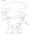
An embodiment of the present invention is illustrated in FIG. 5. To show how this arrangement relates to the arrangements illustrated in FIG. 2, like components have been given like reference numbers.
As can readily be seen by comparison of FIG. 2 and FIG. 5, the main difference between these arrangements is the provision of a dedicated point-to-point interconnect 500 between the public internet service provider 102 and the satellite hub 206. In normal operation, communications between the public network 104 and the client device 100 are routed by the public internet service provider 102 using the first link 116. However, if the first link 116 or the router 112 fail, communications from the public network are re-routed by the public internet service provider via the dedicated point-to-point interconnect to the satellite hub 206 which then forwards the communications to the client system 100 via the satellite 202.
While in FIG. 5, the public network service provide 102 is shown as having a single router 114, it will be understood that it may have a plurality of routers which may be interconnected. The first link 116 and the dedicated point-to-point interconnect 500 may be connected to different routers in the public network service provider 102 such that if one router fails, the other router may still be utilized.
A more detailed implementation of the present invention is illustrated in FIG. 6. It can be seen that this implementation is based on a modification of the architecture illustrated in FIG. 4. The difference between the arrangements illustrated in FIGS. 4 and 6 lies in the choice of routing protocols and the provision of a means of tunneling between the primary ISP and the satellite hub in order to provide a high speed dedicated point-to-point interconnect therebetween. In order to arrive at the arrangement illustrated in FIG. 6, from that illustrated, for example, in FIG. 4, the following modifications may be made.
A router in the primary ISP is modified, or an additional router is provided, to use a suitable private routing protocol such as an interior gateway protocol like RIP. A modified/additional router supporting the private routing protocol is also provided in the satellite hub. A dedicated point-to-point interconnect is made between the two routers in order to provide a high speed interconnect therebetween. This may be done using a virtual interconnect or by providing a physical interconnect.
The interior gateway protocol used may be agreed upon between the Primary ISP and the satellite hub provider. This may be a distance-vector such as RIP or IGRP (interior gateway routing protocol), or a link-state such as OSPF (open shortest path first) or IS-IS (intermediate system to intermediate system). Coupled with policy-based routing, the interior gateway protocol can detect failure of the customer's primary router, the link between the customer and the primary ISP (e.g. via a wireless area network—WAN), or an upstream router, and then route ingress traffic over the high speed dedicated point-to-point interconnect between the ISP network and the satellite hub provider's network.
Static routing can be employed in the satellite network side, on the assumption that any ingress traffic arriving via the high speed dedicated point-to-point interconnect will always be routed via the satellite link.
Egress traffic may be protected from link failure between the customer and the public Internet service provider (e.g. terrestrial WAN failure) in the following manner.
To provide default gateway redundancy to the customer's server farm, either HSRP (Hot Standby Router Protocol) or VRRP (Virtual Router Redundancy Protocol-RFC2338, standard-based) may be used on the pair of customer routers. Using these protocols, one of the routers (primary) will respond to a virtual IP address which may be configured as the default gateway address on the servers. In the case of primary router failure, the secondary router will detect this failure and start to respond to the virtual address. In the present case, the router with the link to the Primary ISP may be configured as the primary router and the router with the link to the satellite hub provider may be configured as the secondary router. Switchover time for HSRP with default timers is 10 seconds. Switchover time for VRRP with default timers is 4 seconds. To take into account slow routing protocol convergence, “pre-empt timeout” may be configured to allow enough time for the routing protocol to converge. Without this command, HSRP/VRRP may switchover faster than routing protocol can recalculate its routing table. Then the customer equipment will have already forwarded traffic to the correct router, but the routing protocol on this router will still not be ready to route this traffic correctly. This will result in a so called “black hole”. As such, a “pre-empt timeout” may be used to make HSRP/VRRP wait for the routing protocol to converge.
The dedicated point-to-point interconnect between the Primary ISP and the satellite hub, over which customer traffic is routed when terrestrial failure occurs, can be built in various ways depending on cost and quality of service requirements. These include: tunneling over the Internet—lowest cost, no quality of service (QoS) guarantees, traffic in the clear; VPN (Virtual Private Network) tunnel over the Internet—low cost, no QoS guarantees, traffic encrypted; controlled routing over the Internet—low cost, some QoS guarantees; physical cross connect in common internet exchange or carrier neutral co-lo (co-location)—higher cost, QoS guarantee, secure route; or leased line—most expensive.
Embodiments of the present invention offer the following advantageous features: one stop solution with quality of service (via ISP sales channel); truly physical diversity (satellite and not terrestrial); ubiquitous (satellite coverage); low cost; and fully transparent using standard protocols.
While this invention has been particularly shown and described with reference to preferred embodiments, it will be understood to those skilled in the art that various changes in form and detail may be made without departing from the scope of the invention as defined by the appended claims.

Claims (27)

The invention claimed is:
1. A communications system comprising:
a public internet service provider; and
a satellite hub,
wherein the public internet service provider is connectable to a client system by a first link and connectable to an internet by a second link,
wherein the satellite hub is connectable to the client system via a satellite link,
wherein the public internet service provider and the satellite hub are connected by a dedicated point-to-point interconnect, and
wherein the public internet service provider is configured to detect failure of the first link between the public internet service provider and the client system and re-route outbound and inbound communications to and from the internet to the satellite hub via the interconnect between the public internet service provider and the satellite hub in the event that the first link between the internet service provider and the client system fails, thereby providing a back-up route to the client system; and
wherein the internet service provider is arranged to receive new communications for the client system from internet users in said internet who have not received a communication from the client system via the back-up route and who do not have visibility of the back-up route and reroute the new communications via the dedicated point-to-point interconnect, such that the back-up route is transparent to said internet users in event of said failure.
2. A communications system according to claim 1, wherein the interconnect is one of: a virtual interconnect between the public internet service provider and the satellite hub over internet; and a physical interconnect between the public internet service provider and the satellite hub.
3. A communications system according to claim 1, wherein the interconnect is provided by one of: tunnelling over internet; vpn (virtual private network) tunnelling over internet; controlled routing over internet; a physical cross connect; a common internet exchange; a carrier neutral co-location; and a leased line.
4. A communications system according to claim 1, wherein the internet service provider and the satellite hub are adapted to utilize a common private routing protocol for routing communications via the interconnect.
5. A communications system according to claim 4, wherein the internet service provider is adapted to translate between a public dynamic routing protocol used by routers in the internet and the common private routing protocol.
6. A communications system according to claim 4, wherein the common private routing protocol is one of dynamic and static.
7. A communications system according to claim 4, wherein the common private routing protocol is an interior gateway protocol (igp).
8. A communications system according to claim 1, wherein the satellite hub is adapted to be further connectable to internet.
9. The communications system of claim 1, wherein the internet service provider provides internet access to a plurality of organizations and said client system is a client system of one of said organizations, the internet service provider being outside of any of the organizations' own networks, and the first link providing a connection between said one of the organizations and the public internet service provider outside the organizations.
10. The communication system of claim 9, wherein each of said organizations comprises a respective headquarters and the internet service provider is outside of said headquarters.
11. The communications system of claim 9, wherein the internet service provider provides said back-up route without incorporating a satellite backup connection within any of said organizations' own networks.
12. A public internet service provider comprising:
a first link for connecting the public internet service provider to a client system;
a second link for connecting the public internet service provider to an internet; and
a dedicated point-to-point interconnect for connecting the public internet service provider to a satellite hub, and
wherein the public internet service provider is configured to detect failure of the first link between the public internet service provider and the client system and re-route outbound and inbound communications to and from the internet to the satellite hub via the interconnect between the public internet service provider and the client system fails, thereby providing a back-up route to the client system; and
wherein the internet service provider is arranged to receive new communications for the client system from internet users in said internet who have not received a communication from the client system via the back-up route and who do not have visibility of the back-up route and reroute the new communications via the dedicated point-to-point interconnect, such that the back-up route is transparent to said internet users in event of said failure.
13. The public internet service provider according to claim 12, wherein the interconnect is one of: a virtual interconnect between the public internet service provider and the satellite hub over the internet; and a physical interconnect between the satellite hub and the public internet service provider.
14. The public internet service provider according to claim 12, wherein the interconnect is provided by one of: tunnelling over the internet; VPN (virtual private network) tunnelling over the internet; controlled routing over the internet; a physical cross connect; a common internet exchange; a carrier neutral co-location; and a leased line.
15. The public internet service provider according to claim 12, wherein the public internet service provider is adapted to use a private routing protocol for routing communications via the interconnect.
16. The public internet service provider according to claim 15, wherein the public internet service provider is configured to translate between a public dynamic routing protocol used by routers in the internet and the private routing protocol.
17. The public internet service provider according to claim 15, wherein the private routing protocol is one of dynamic and static.
18. The public internet service provider according to claim 17, wherein the private routing protocol is an interior gateway protocol (igp).
19. A satellite hub comprising:
a satellite link for connecting the satellite hub to a client system
and a dedicated point-to-point interconnect for connecting the satellite hub to a public internet service provider
wherein the satellite hub is configured to communicate with the public internet service provider whereby when the public internet service provider detects a failure of a primary connection between the client system and an internet, outbound and inbound communications to and from the internet are re-routed through the satellite hub to the client system via the dedicated point-to-point interconnect, thereby providing a back-up route to the client system; and
wherein the internet service provider is arranged to receive new communications for the client system from internet users in said internet who have not received a communication from the client system via the back-up route and who do not have visibility of the back-up route and reroute the new communications via the dedicated point-to-point interconnect, such that the back-up route is transparent to said internet users in event of said failure.
20. A satellite hub according to claim 19, wherein the interconnect is one of: a virtual interconnect between the satellite hub and the public internet service provider over the internet; and a physical interconnect between the satellite hub and the public internet service provider.
21. A satellite hub according to claim 19, wherein the interconnect is provided by one of: tunnelling over the internet; vpn (virtual private network) tunnelling over the internet; controlled routing over the internet; a physical cross connect; a common internet exchange; a carrier neutral co-location; and a leased line.
22. A satellite hub according to claim 19, wherein the satellite hub is adapted to use a private routing protocol for routing communications via the interconnect.
23. A satellite hub according to claim 22, wherein the private routing protocol is one of dynamic and static.
24. A satellite hub according to claim 23, wherein the private routing protocol is an interior gateway protocol (igp).
25. A communications network comprising:
a client system comprising a satellite transceiver;
a public internet service provider supporting a public dynamic routing protocol;
an internet comprising a plurality of routers supporting the public dynamic routing protocol;
a satellite hub comprising a satellite transceiver; and
a satellite, wherein the client system is connected to the public internet service provider by a first link,
wherein the public internet service provider is connected to the internet by a second link, and the satellite hub and the client system are connected via the satellite and the satellite transceivers, wherein the public internet service provider and the satellite hub are connected by a dedicated point-to-point interconnect, and
wherein the public internet service provider is configured to detect failure of the first link between the public internet service provider and the client system, and re-route outbound and inbound communications to and from the internet to the satellite hub via the interconnect between the public internet service provider and the satellite hub in the event that the first link between the public internet service provider and the client system fails, thereby providing a back-up route to the client system; and
wherein the internet service provider is arranged to receive new communications for the client system from internet users in said internet who have not received a communication from the client system via the back-up route and who do not have visibility of the back-up route and reroute the new communications via the dedicated point-to-point interconnect, such that the back-up route is transparent to said internet users in event of said failure.
26. A method for providing connectivity between a client system and an internet, the method comprising:
providing a public internet service provider and a satellite hub with a dedicated point-to-point interconnect therebetween;
routing communications from the internet to the client device via a first link in normal operation; and
re-routing communications from the internet via the dedicated point-to-point interconnect when the first link fails,
wherein the public internet service provider detects failure of the first link between the public internet service provider and the client system and re-routes outbound and inbound communications to and from the internet to the satellite hub via the dedicated point-to-point interconnect between the public internet service provider and the satellite hub when failure of the first link is detected, thereby providing a back-up route to the client system; and
wherein the internet service provider is arranged to receive new communications for the client system from internet users in said internet who have not received a communication from the client system via the back-up route and who do not have visibility of the back-up route and reroute the new communications via the dedicated point-to-point interconnect, such that the back-up route is transparent to said internet users in event of said failure.
27. A communications system comprising:
a private network comprising at least one client system and a headquarters;
a public internet service provider outside of said private network; and
a satellite hub; and
wherein the public internet service provider is connectable by a first link to the private network, and is connectable to the internet by a second link;
wherein the satellite hub is connectable to the private network via a satellite link;
wherein the public internet service provider and the satellite hub are connected by a dedicated point-to-point interconnect; and
wherein the public internet service provider comprises a detector configured to detect failure of the first link between the public internet service provider and the private network, and a router configured to re-route outbound and inbound communications to and from the internet to the satellite hub via the interconnect between the public internet service provider and the satellite hub in the event that the first link between the public internet service provider and the private network fails, thereby providing a back-up route to the client system; and
wherein the internet service provider is arranged to receive new communications for the client system from internet users in said internet who have not received a communication from the client system via the back-up route and who do not have visibility of the back-up route and reroute the new communications via the dedicated point-to-point interconnect, such that the back-up route is transparent to said internet users in event of said failure.
US12/600,587 2007-05-18 2008-05-09 Backup network connectivity Expired - Fee Related US8861341B2 (en)

Applications Claiming Priority (3)

Application Number Priority Date Filing Date Title
GB0709623A GB2449311B (en) 2007-05-18 2007-05-18 Backup network connectivity
GB0709623.3 2007-05-18
PCT/EP2008/055786 WO2008141961A1 (en) 2007-05-18 2008-05-09 Backup network connectivity

Publications (2)

Publication Number Publication Date
US20110032865A1 US20110032865A1 (en) 2011-02-10
US8861341B2 true US8861341B2 (en) 2014-10-14

Family

ID=38234727

Family Applications (1)

Application Number Title Priority Date Filing Date
US12/600,587 Expired - Fee Related US8861341B2 (en) 2007-05-18 2008-05-09 Backup network connectivity

Country Status (10)

Country Link
US (1) US8861341B2 (en)
EP (1) EP2151102B1 (en)
CY (1) CY1113572T1 (en)
ES (1) ES2392953T3 (en)
GB (1) GB2449311B (en)
HR (1) HRP20120959T1 (en)
PL (1) PL2151102T3 (en)
PT (1) PT2151102E (en)
SI (1) SI2151102T1 (en)
WO (1) WO2008141961A1 (en)

Cited By (2)

* Cited by examiner, † Cited by third party
Publication number Priority date Publication date Assignee Title
US10051338B2 (en) 2015-10-21 2018-08-14 At&T Intellectual Property I, L.P. System and method for coordinating back-up services for land based content subscribers
US10110481B2 (en) 2015-05-19 2018-10-23 Cisco Technology, Inc. Virtual network functions with high availability in public clouds

Families Citing this family (11)

* Cited by examiner, † Cited by third party
Publication number Priority date Publication date Assignee Title
GB2449311B (en) 2007-05-18 2009-07-29 Avanti Comm Group Plc Backup network connectivity
US8576725B2 (en) 2010-08-13 2013-11-05 Avaya Inc. Failover based on sending communications between different domains
US8565073B2 (en) * 2010-08-18 2013-10-22 At&T Intellectual Property I, L.P. Dynamic rerouting of data paths in a wireless communication network
US8675543B2 (en) * 2011-02-24 2014-03-18 Verizon Patent And Licensing Inc. Route limiting in border gateway protocol over satellite networks
US9026845B2 (en) * 2012-05-15 2015-05-05 Dell Products L.P. System and method for failure protection in a storage array
CN103974454B (en) * 2013-01-28 2017-10-31 财团法人资讯工业策进会 Transmission end direct communication device, receiving terminal direct communication device and its communication path switch method
CN104168193B (en) * 2014-08-12 2017-12-15 华为技术有限公司 A kind of method and routing device of Virtual Router Redundancy Protocol fault detect
GB2540945B (en) * 2015-07-31 2017-12-06 Avanti Communications Group Plc Satellite operations support system
CN106452854B (en) * 2016-09-27 2019-04-26 南京国电南自轨道交通工程有限公司 A kind of subway comprehensive monitoring system synchronous communication method based on multi-connection master-slave redundancy
US10326689B2 (en) * 2016-12-08 2019-06-18 At&T Intellectual Property I, L.P. Method and system for providing alternative communication paths
US11470677B2 (en) 2020-08-27 2022-10-11 Dish Network L.L.C. Systems and methods for a computer network intermediate router

Citations (12)

* Cited by examiner, † Cited by third party
Publication number Priority date Publication date Assignee Title
US6038594A (en) * 1998-02-02 2000-03-14 Loral Cyberstar, Inc. Internet communication system and method with asymmetric terrestrial and satellite links
WO2001088737A1 (en) 2000-05-15 2001-11-22 Pentamedia Co., Ltd. Method and apparatus for providing satellite internet service to satellite internet terminal not joined in terrestrial internet line of satellite internet service provider
US20030204617A1 (en) 2002-04-24 2003-10-30 Intelsat Satellite internet communication system and method
US6748439B1 (en) * 1999-08-06 2004-06-08 Accelerated Networks System and method for selecting internet service providers from a workstation that is connected to a local area network
US6779039B1 (en) 2000-03-31 2004-08-17 Avaya Technology Corp. System and method for routing message traffic using a cluster of routers sharing a single logical IP address distinct from unique IP addresses of the routers
US20050008017A1 (en) 2000-12-29 2005-01-13 Ragula Systems D/B/A Fatpipe Networks Tools and techniques for directing packets over disparate networks
US20050089015A1 (en) * 2003-10-24 2005-04-28 Hitachi Communication Technologies, Ltd. Communication apparatus and method for inter-as routing
US20060146696A1 (en) 2005-01-06 2006-07-06 At&T Corp. Bandwidth management for MPLS fast rerouting
US20070011268A1 (en) * 2005-03-22 2007-01-11 Banga Jasminder S Systems and methods of network operation and information processing, including engaging users of a public-access network
US20070038767A1 (en) * 2003-01-09 2007-02-15 Miles Kevin G Method and apparatus for constructing a backup route in a data communications network
US20080219268A1 (en) * 2007-03-01 2008-09-11 Dennison Larry R Software control plane for switches and routers
GB2449311B (en) 2007-05-18 2009-07-29 Avanti Comm Group Plc Backup network connectivity

Family Cites Families (1)

* Cited by examiner, † Cited by third party
Publication number Priority date Publication date Assignee Title
EP1202507A1 (en) * 2000-10-31 2002-05-02 BRITISH TELECOMMUNICATIONS public limited company Telecommunications systems

Patent Citations (12)

* Cited by examiner, † Cited by third party
Publication number Priority date Publication date Assignee Title
US6038594A (en) * 1998-02-02 2000-03-14 Loral Cyberstar, Inc. Internet communication system and method with asymmetric terrestrial and satellite links
US6748439B1 (en) * 1999-08-06 2004-06-08 Accelerated Networks System and method for selecting internet service providers from a workstation that is connected to a local area network
US6779039B1 (en) 2000-03-31 2004-08-17 Avaya Technology Corp. System and method for routing message traffic using a cluster of routers sharing a single logical IP address distinct from unique IP addresses of the routers
WO2001088737A1 (en) 2000-05-15 2001-11-22 Pentamedia Co., Ltd. Method and apparatus for providing satellite internet service to satellite internet terminal not joined in terrestrial internet line of satellite internet service provider
US20050008017A1 (en) 2000-12-29 2005-01-13 Ragula Systems D/B/A Fatpipe Networks Tools and techniques for directing packets over disparate networks
US20030204617A1 (en) 2002-04-24 2003-10-30 Intelsat Satellite internet communication system and method
US20070038767A1 (en) * 2003-01-09 2007-02-15 Miles Kevin G Method and apparatus for constructing a backup route in a data communications network
US20050089015A1 (en) * 2003-10-24 2005-04-28 Hitachi Communication Technologies, Ltd. Communication apparatus and method for inter-as routing
US20060146696A1 (en) 2005-01-06 2006-07-06 At&T Corp. Bandwidth management for MPLS fast rerouting
US20070011268A1 (en) * 2005-03-22 2007-01-11 Banga Jasminder S Systems and methods of network operation and information processing, including engaging users of a public-access network
US20080219268A1 (en) * 2007-03-01 2008-09-11 Dennison Larry R Software control plane for switches and routers
GB2449311B (en) 2007-05-18 2009-07-29 Avanti Comm Group Plc Backup network connectivity

Non-Patent Citations (3)

* Cited by examiner, † Cited by third party
Title
British Search Report dated Aug. 31, 2007, from corresponding International Application No. PCT/EP2008/055786.
International Search Report dated Sep. 15, 2008, from corresponding International Application No. PCT/EP2008/055786.
Response to Search Examination Report filed on May 7, 2009, pp. 1-4, and amended pp. 5, 5a, 9, 9a, 10, and 15-19.

Cited By (3)

* Cited by examiner, † Cited by third party
Publication number Priority date Publication date Assignee Title
US10110481B2 (en) 2015-05-19 2018-10-23 Cisco Technology, Inc. Virtual network functions with high availability in public clouds
US10051338B2 (en) 2015-10-21 2018-08-14 At&T Intellectual Property I, L.P. System and method for coordinating back-up services for land based content subscribers
US10390099B2 (en) 2015-10-21 2019-08-20 At&T Intellectual Property I, L.P. System and method for coordinating back-up services for land based content subscribers

Also Published As

Publication number Publication date
GB2449311A (en) 2008-11-19
CY1113572T1 (en) 2016-06-22
US20110032865A1 (en) 2011-02-10
WO2008141961A1 (en) 2008-11-27
GB0709623D0 (en) 2007-06-27
GB2449311B (en) 2009-07-29
SI2151102T1 (en) 2013-01-31
HRP20120959T1 (en) 2012-12-31
EP2151102B1 (en) 2012-08-29
ES2392953T3 (en) 2012-12-17
PL2151102T3 (en) 2013-01-31
EP2151102A1 (en) 2010-02-10
PT2151102E (en) 2012-11-14

Similar Documents

Publication Publication Date Title
US8861341B2 (en) Backup network connectivity
US11743167B2 (en) System and method for next hop BGP routing in a network
US11018758B2 (en) Mobility across satellite beams using L2 connectivity
US8787149B1 (en) MAC address synchronization for multi-homing with multichassis link aggregation
CN107547366B (en) Message forwarding method and device
EP2502389B1 (en) Method for the provision of gateway anycast virtual mac reachability in extended subnets
EP3373547B1 (en) Method for realizing disaster tolerance backup
US8264947B1 (en) Fault tolerant wireless access system and method
US8427999B2 (en) Multi-satellite architecture
US8279748B2 (en) Core-based satellite network architecture
EP1699186B1 (en) System and method for achieving path symmetry in an IP based network
EP1011231A2 (en) Method and apparatus providing for router redundancy of non internet protocols using the virtual router redundancy protocol
WO2021227863A1 (en) Disaster recovery method and apparatus for hybrid cloud private line access network
US20060098665A1 (en) Systems and methods for communicating with bi-nodal network elements
KR20210037086A (en) network switching administrating method utilizing virtual anycast node
Funakura Border Gateway Protocol Best Practices

Legal Events

Date Code Title Description
AS Assignment

Owner name: AVANTI BROADBAND LIMITED, UNITED KINGDOM

Free format text: ASSIGNMENT OF ASSIGNORS INTEREST;ASSIGNOR:RICHARDSON, SCOTT;REEL/FRAME:024799/0030

Effective date: 20100804

AS Assignment

Owner name: AVANTI BROADBAND LIMITED, UNITED KINGDOM

Free format text: CORRECTIVE ASSIGNMENT TO CORRECT THE TYPE OF COMPANY PREVIOUSLY RECORDED ON REEL 024799 FRAME 0030. ASSIGNOR(S) HEREBY CONFIRMS THE THE NAME OF THE ASSIGNEE SHOULD IDENTIFY THE COMPANY AS A PRIVATE COMPANY;ASSIGNOR:RICHARDSON, SCOTT;REEL/FRAME:027149/0904

Effective date: 20100804

FEPP Fee payment procedure

Free format text: MAINTENANCE FEE REMINDER MAILED (ORIGINAL EVENT CODE: REM.)

LAPS Lapse for failure to pay maintenance fees

Free format text: PATENT EXPIRED FOR FAILURE TO PAY MAINTENANCE FEES (ORIGINAL EVENT CODE: EXP.); ENTITY STATUS OF PATENT OWNER: LARGE ENTITY

STCH Information on status: patent discontinuation

Free format text: PATENT EXPIRED DUE TO NONPAYMENT OF MAINTENANCE FEES UNDER 37 CFR 1.362

FP Lapsed due to failure to pay maintenance fee

Effective date: 20181014