US8882845B2 - Mobile bearing glenoid prosthesis - Google Patents
Mobile bearing glenoid prosthesis Download PDFInfo
- Publication number
- US8882845B2 US8882845B2 US13/094,180 US201113094180A US8882845B2 US 8882845 B2 US8882845 B2 US 8882845B2 US 201113094180 A US201113094180 A US 201113094180A US 8882845 B2 US8882845 B2 US 8882845B2
- Authority
- US
- United States
- Prior art keywords
- locking component
- curvature
- glenoid
- radius
- bearing
- Prior art date
- Legal status (The legal status is an assumption and is not a legal conclusion. Google has not performed a legal analysis and makes no representation as to the accuracy of the status listed.)
- Active, expires
Links
Images


Classifications
-
- A—HUMAN NECESSITIES
- A61—MEDICAL OR VETERINARY SCIENCE; HYGIENE
- A61F—FILTERS IMPLANTABLE INTO BLOOD VESSELS; PROSTHESES; DEVICES PROVIDING PATENCY TO, OR PREVENTING COLLAPSING OF, TUBULAR STRUCTURES OF THE BODY, e.g. STENTS; ORTHOPAEDIC, NURSING OR CONTRACEPTIVE DEVICES; FOMENTATION; TREATMENT OR PROTECTION OF EYES OR EARS; BANDAGES, DRESSINGS OR ABSORBENT PADS; FIRST-AID KITS
- A61F2/00—Filters implantable into blood vessels; Prostheses, i.e. artificial substitutes or replacements for parts of the body; Appliances for connecting them with the body; Devices providing patency to, or preventing collapsing of, tubular structures of the body, e.g. stents
- A61F2/02—Prostheses implantable into the body
- A61F2/30—Joints
- A61F2/40—Joints for shoulders
- A61F2/4081—Glenoid components, e.g. cups
-
- A—HUMAN NECESSITIES
- A61—MEDICAL OR VETERINARY SCIENCE; HYGIENE
- A61F—FILTERS IMPLANTABLE INTO BLOOD VESSELS; PROSTHESES; DEVICES PROVIDING PATENCY TO, OR PREVENTING COLLAPSING OF, TUBULAR STRUCTURES OF THE BODY, e.g. STENTS; ORTHOPAEDIC, NURSING OR CONTRACEPTIVE DEVICES; FOMENTATION; TREATMENT OR PROTECTION OF EYES OR EARS; BANDAGES, DRESSINGS OR ABSORBENT PADS; FIRST-AID KITS
- A61F2/00—Filters implantable into blood vessels; Prostheses, i.e. artificial substitutes or replacements for parts of the body; Appliances for connecting them with the body; Devices providing patency to, or preventing collapsing of, tubular structures of the body, e.g. stents
- A61F2/02—Prostheses implantable into the body
- A61F2/30—Joints
- A61F2002/30001—Additional features of subject-matter classified in A61F2/28, A61F2/30 and subgroups thereof
- A61F2002/30108—Shapes
- A61F2002/3011—Cross-sections or two-dimensional shapes
- A61F2002/30112—Rounded shapes, e.g. with rounded corners
- A61F2002/30125—Rounded shapes, e.g. with rounded corners elliptical or oval
-
- A—HUMAN NECESSITIES
- A61—MEDICAL OR VETERINARY SCIENCE; HYGIENE
- A61F—FILTERS IMPLANTABLE INTO BLOOD VESSELS; PROSTHESES; DEVICES PROVIDING PATENCY TO, OR PREVENTING COLLAPSING OF, TUBULAR STRUCTURES OF THE BODY, e.g. STENTS; ORTHOPAEDIC, NURSING OR CONTRACEPTIVE DEVICES; FOMENTATION; TREATMENT OR PROTECTION OF EYES OR EARS; BANDAGES, DRESSINGS OR ABSORBENT PADS; FIRST-AID KITS
- A61F2/00—Filters implantable into blood vessels; Prostheses, i.e. artificial substitutes or replacements for parts of the body; Appliances for connecting them with the body; Devices providing patency to, or preventing collapsing of, tubular structures of the body, e.g. stents
- A61F2/02—Prostheses implantable into the body
- A61F2/30—Joints
- A61F2002/30001—Additional features of subject-matter classified in A61F2/28, A61F2/30 and subgroups thereof
- A61F2002/30316—The prosthesis having different structural features at different locations within the same prosthesis; Connections between prosthetic parts; Special structural features of bone or joint prostheses not otherwise provided for
- A61F2002/30329—Connections or couplings between prosthetic parts, e.g. between modular parts; Connecting elements
- A61F2002/30331—Connections or couplings between prosthetic parts, e.g. between modular parts; Connecting elements made by longitudinally pushing a protrusion into a complementarily-shaped recess, e.g. held by friction fit
- A61F2002/30332—Conically- or frustoconically-shaped protrusion and recess
-
- A—HUMAN NECESSITIES
- A61—MEDICAL OR VETERINARY SCIENCE; HYGIENE
- A61F—FILTERS IMPLANTABLE INTO BLOOD VESSELS; PROSTHESES; DEVICES PROVIDING PATENCY TO, OR PREVENTING COLLAPSING OF, TUBULAR STRUCTURES OF THE BODY, e.g. STENTS; ORTHOPAEDIC, NURSING OR CONTRACEPTIVE DEVICES; FOMENTATION; TREATMENT OR PROTECTION OF EYES OR EARS; BANDAGES, DRESSINGS OR ABSORBENT PADS; FIRST-AID KITS
- A61F2/00—Filters implantable into blood vessels; Prostheses, i.e. artificial substitutes or replacements for parts of the body; Appliances for connecting them with the body; Devices providing patency to, or preventing collapsing of, tubular structures of the body, e.g. stents
- A61F2/02—Prostheses implantable into the body
- A61F2/30—Joints
- A61F2002/30001—Additional features of subject-matter classified in A61F2/28, A61F2/30 and subgroups thereof
- A61F2002/30316—The prosthesis having different structural features at different locations within the same prosthesis; Connections between prosthetic parts; Special structural features of bone or joint prostheses not otherwise provided for
- A61F2002/30329—Connections or couplings between prosthetic parts, e.g. between modular parts; Connecting elements
- A61F2002/30331—Connections or couplings between prosthetic parts, e.g. between modular parts; Connecting elements made by longitudinally pushing a protrusion into a complementarily-shaped recess, e.g. held by friction fit
- A61F2002/30362—Connections or couplings between prosthetic parts, e.g. between modular parts; Connecting elements made by longitudinally pushing a protrusion into a complementarily-shaped recess, e.g. held by friction fit with possibility of relative movement between the protrusion and the recess
- A61F2002/30364—Rotation about the common longitudinal axis
-
- A—HUMAN NECESSITIES
- A61—MEDICAL OR VETERINARY SCIENCE; HYGIENE
- A61F—FILTERS IMPLANTABLE INTO BLOOD VESSELS; PROSTHESES; DEVICES PROVIDING PATENCY TO, OR PREVENTING COLLAPSING OF, TUBULAR STRUCTURES OF THE BODY, e.g. STENTS; ORTHOPAEDIC, NURSING OR CONTRACEPTIVE DEVICES; FOMENTATION; TREATMENT OR PROTECTION OF EYES OR EARS; BANDAGES, DRESSINGS OR ABSORBENT PADS; FIRST-AID KITS
- A61F2/00—Filters implantable into blood vessels; Prostheses, i.e. artificial substitutes or replacements for parts of the body; Appliances for connecting them with the body; Devices providing patency to, or preventing collapsing of, tubular structures of the body, e.g. stents
- A61F2/02—Prostheses implantable into the body
- A61F2/30—Joints
- A61F2002/30001—Additional features of subject-matter classified in A61F2/28, A61F2/30 and subgroups thereof
- A61F2002/30316—The prosthesis having different structural features at different locations within the same prosthesis; Connections between prosthetic parts; Special structural features of bone or joint prostheses not otherwise provided for
- A61F2002/30329—Connections or couplings between prosthetic parts, e.g. between modular parts; Connecting elements
- A61F2002/30476—Connections or couplings between prosthetic parts, e.g. between modular parts; Connecting elements locked by an additional locking mechanism
- A61F2002/305—Snap connection
-
- A—HUMAN NECESSITIES
- A61—MEDICAL OR VETERINARY SCIENCE; HYGIENE
- A61F—FILTERS IMPLANTABLE INTO BLOOD VESSELS; PROSTHESES; DEVICES PROVIDING PATENCY TO, OR PREVENTING COLLAPSING OF, TUBULAR STRUCTURES OF THE BODY, e.g. STENTS; ORTHOPAEDIC, NURSING OR CONTRACEPTIVE DEVICES; FOMENTATION; TREATMENT OR PROTECTION OF EYES OR EARS; BANDAGES, DRESSINGS OR ABSORBENT PADS; FIRST-AID KITS
- A61F2/00—Filters implantable into blood vessels; Prostheses, i.e. artificial substitutes or replacements for parts of the body; Appliances for connecting them with the body; Devices providing patency to, or preventing collapsing of, tubular structures of the body, e.g. stents
- A61F2/02—Prostheses implantable into the body
- A61F2/30—Joints
- A61F2/30767—Special external or bone-contacting surface, e.g. coating for improving bone ingrowth
- A61F2002/30934—Special articulating surfaces
-
- A—HUMAN NECESSITIES
- A61—MEDICAL OR VETERINARY SCIENCE; HYGIENE
- A61F—FILTERS IMPLANTABLE INTO BLOOD VESSELS; PROSTHESES; DEVICES PROVIDING PATENCY TO, OR PREVENTING COLLAPSING OF, TUBULAR STRUCTURES OF THE BODY, e.g. STENTS; ORTHOPAEDIC, NURSING OR CONTRACEPTIVE DEVICES; FOMENTATION; TREATMENT OR PROTECTION OF EYES OR EARS; BANDAGES, DRESSINGS OR ABSORBENT PADS; FIRST-AID KITS
- A61F2220/00—Fixations or connections for prostheses classified in groups A61F2/00 - A61F2/26 or A61F2/82 or A61F9/00 or A61F11/00 or subgroups thereof
- A61F2220/0025—Connections or couplings between prosthetic parts, e.g. between modular parts; Connecting elements
- A61F2220/0033—Connections or couplings between prosthetic parts, e.g. between modular parts; Connecting elements made by longitudinally pushing a protrusion into a complementary-shaped recess, e.g. held by friction fit
-
- A—HUMAN NECESSITIES
- A61—MEDICAL OR VETERINARY SCIENCE; HYGIENE
- A61F—FILTERS IMPLANTABLE INTO BLOOD VESSELS; PROSTHESES; DEVICES PROVIDING PATENCY TO, OR PREVENTING COLLAPSING OF, TUBULAR STRUCTURES OF THE BODY, e.g. STENTS; ORTHOPAEDIC, NURSING OR CONTRACEPTIVE DEVICES; FOMENTATION; TREATMENT OR PROTECTION OF EYES OR EARS; BANDAGES, DRESSINGS OR ABSORBENT PADS; FIRST-AID KITS
- A61F2230/00—Geometry of prostheses classified in groups A61F2/00 - A61F2/26 or A61F2/82 or A61F9/00 or A61F11/00 or subgroups thereof
- A61F2230/0002—Two-dimensional shapes, e.g. cross-sections
- A61F2230/0004—Rounded shapes, e.g. with rounded corners
- A61F2230/0008—Rounded shapes, e.g. with rounded corners elliptical or oval
Definitions
- the present disclosure relates generally to shoulder prostheses, and more particularly to shoulder prostheses configured for use in shoulders having glenoid vault erosion or defects.
- a typical shoulder or glenohumeral joint is formed in a human body where the humerus 10 movably contacts the scapula 12 as shown in FIG. 1 .
- the scapula 12 includes a glenoid fossa 14 that forms a socket against which the head of the humerus 10 articulates.
- the scapula 12 includes cartilage 16 that facilitates such articulation.
- Beneath the cartilage is subchondral bone 18 that forms a wall of a glenoid vault 20 that defines a cavity which contains cancellous bone 22 .
- the subchondral bone 18 that forms the glenoid vault 20 defines a glenoid rim 21 at a periphery of the glenoid vault that is attached to the cartilage 16 (see FIG. 1 ).
- the glenoid fossa 14 may become worn, especially at its posterior and/or superior portions thereby causing severe shoulder pain and limiting the range of motion of the patient's shoulder joint.
- a shoulder arthroplasty may be performed.
- glenoid fossa Shoulder arthroplasty often involves surgical replacement of the glenoid fossa with a conventional glenoid prosthesis such as the one disclosed in U.S. Pat. No. 6,911,047, the disclosure of which is herein incorporated by reference.
- the glenoid prosthesis when implanted, provides a new laterally-facing bearing surface, which may be concave or convex, for articulation with a complementary bearing surface of a natural or prosthetic humeral head.
- Such conventional glenoid prosthesis is typically formed from UHMW polyethylene, titanium, or cobalt chrome and includes bone anchor(s) such as peg(s), screw(s), post(s), or a keel extending from a back side of the device opposite its bearing surface.
- the back side of the prosthesis is typically secured against subchondral bone of the glenoid vault while the bone anchor(s) may extend into the cavity of the glenoid vault whereby it may become anchored to cancellous bone located within the glenoid vault.
- a prosthesis assembly configured for use with a scapula which includes a spherical humeral component, an elongated glenoid bearing including a first bearing surface with (i) a first spherical end portion with a first radius of curvature, (ii) a second spherical end portion with a second radius of curvature, and (iii) a central portion located between the first spherical end portion and the second spherical end portion, and a first coupling portion extending from a second bearing surface opposite the bearing surface, and a base configured to rotatably support the elongated glenoid bearing, wherein the first radius of curvature is substantially equal to the second radius of curvature and the central portion does not have a radius of curvature that is substantially equal to the second radius of curvature.
- FIG. 1 depicts a cross-sectional view of an anatomically normal glenohumeral joint of a human patient
- FIG. 2 depicts a perspective view of a shoulder prosthesis assembly of the present disclosure
- FIG. 3 depicts an end cross-sectional view of the glenoid bearing base of FIG. 2 ;
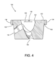
- FIG. 4 depicts a side cross-sectional view of the glenoid bearing base of FIG. 2 ;
- FIG. 5 depicts a top plan view of the base of FIG. 2 ;
- FIG. 6 depicts a perspective view of the glenoid bearing of FIG. 2 ;
- FIG. 6A depicts a cross sectional view of a spherical humeral component that may be used with the glenoid bearing of FIG. 6 ;
- FIG. 7 depicts an end plan view of the glenoid bearing of FIG. 6 ;
- FIG. 8 depicts a side cross-sectional view of the glenoid bearing of FIG. 6 ;
- FIG. 9 depicts a top perspective view of a shoulder assembly prosthesis with a stretched bearing component that does not include a rim replacement vault
- FIG. 10 depicts a bottom perspective view of the shoulder assembly prosthesis of FIG. 9 ;
- FIG. 11 depicts a top plan view of the shoulder assembly prosthesis of FIG. 9 ;
- FIG. 12 depicts a cross-sectional view of the shoulder assembly prosthesis
- FIG. 13 depicts a cross-sectional view of a shoulder assembly prosthesis with a stretched bearing component which is snap-fit to a base component;
- FIG. 14 depicts a partial cross-sectional view of the mating recess of the base component of FIG. 13 ;
- FIG. 15 depicts a partial plan view of the mating portion of the stretched bearing component of FIG. 13 .
- the prosthesis assembly 100 includes a glenoid base component 102 and a glenoid bearing 104 .
- the glenoid base component 102 in this embodiment is made entirely of a metallic material, while the glenoid bearing 104 is made entirely of a polymeric material.
- the glenoid base component 102 is made of a biological grade stainless steel or titanium material.
- the glenoid bearing support may include a porous-coating on its entire outer surface to facilitate biological ingrowth of a patient's bone.
- the glenoid bearing 104 is preferably made entirely of a polymer such as polyethylene.
- One particular polyethylene that is well suited for use as the bearing component is a high molecular weight polyethylene, for example, ultra-high molecular weight polyethylene (UHMWPE).
- the glenoid base component 102 is described with further reference to FIGS. 3 and 4 .
- the glenoid base component 102 includes a glenoid vault-occupying portion 106 and a glenoid rim replacement portion 108 .
- the glenoid rim replacement portion 108 is attached to the glenoid vault-occupying portion 106 as shown in FIGS. 3-4 .
- the glenoid rim replacement portion 108 and the glenoid vault-occupying portion 106 may be attached to each other by being integrally formed together as a single part.
- the glenoid rim replacement portion 108 and the glenoid vault-occupying portion 106 may be separately formed.
- a cavity may be formed in the glenoid vault-occupying portion 106 which receives a complementary shaped cavity occupying portion of the glenoid rim replacement portion 108 .
- the separately formed glenoid rim replacement portion 108 and glenoid vault-occupying portion 106 may be attached to each other by snap-fit or friction-fit features or the like.
- One such friction fit feature is a ball taper connection which allows for version correction of the glenoid rim replacement portion 108 independent of the version of the glenoid vault-occupying portion 106 .
- soft tissue may be relied upon to maintain the glenoid rim replacement portion 108 mated with the glenoid vault-occupying portion 106 .
- the glenoid vault-occupying portion 106 is configured to occupy at least a portion of the glenoid vault of a scapula, such as the glenoid vault 20 shown in FIG. 1 . If desired, the glenoid vault-occupying portion 106 may configured to substantially completely fill the glenoid vault of a scapula, such as glenoid vault 20 shown in FIG. 1 .
- the glenoid vault-occupying portion 106 has an exterior wall 110 and an exterior wall 112 as best shown in FIG. 3 . When the glenoid vault-occupying portion 106 is viewed in cross-section (see FIG. 3 ) the exterior wall 110 and the exterior wall 112 are positioned with respect to each other to define a generally V-shaped wedge 114 .
- the glenoid vault-occupying portion 106 has a mating portion 120 which extends inwardly from a bearing surface 122 .
- the bearing surface 122 provides support for the glenoid rim replacement portion 108 and may be polished to reduce generation of wear products.
- the mating portion 120 includes a wall portion 124 which defines a generally cone shaped inner periphery of the base 102 .
- a ridge 126 and a ridge 128 extend into the recess formed by the wall portion 124 .
- the ridges 126 and 128 extend partially along the inner periphery defined by the wall portion 124 .
- a rim 130 extends from the bearing surface 122 .
- the rim 130 and wedge 114 define a pocket 132 which extends completely about the wedge 114 . If desired, bone graft material may be placed into the pocket 132 .
- the glenoid vault-occupying portion 106 further includes fastener channels 134 and 136 . Fasteners may be inserted through the mating recess 120 and through the channels 134 and 136 to affix the glenoid base component 102 to a glenoid.
- the glenoid bearing 104 is shown in more detail in FIGS. 6-8 .
- the bearing 104 includes a body 140 and a mating member 142 .
- the body 140 includes a bearing surface 144 configured to articulate with a spherical humerus component, such as the spherical humeral component 30 shown in FIG. 6A with a glenoid component 32 , and a bearing surface 145 configured to articulate with the bearing surface 122 .
- the glenoid bearing 104 is a stretched bearing.
- a “stretched bearing” is a bearing that includes a bearing surface with at least three distinct geometries.
- the bearing surface 144 includes an outer bearing portion 146 , a central bearing portion 148 , and an outer bearing portion 150 .
- the outer bearing portion 146 is spherically shaped with a radius of curvature 152 and the outer bearing portion 150 is spherically shaped with a radius of curvature 154 .
- the radius of curvature 152 is preferably the same length as the radius of curvature 154 .
- the central portion 148 has a radius of curvature 156 that is much larger than the radius of curvature 152 and the radius of curvature 154 .
- the central portion 148 includes a substantially planar portion.
- a rim 158 extends completely around the bearing surface 144 .
- the mating member 142 includes a wall 160 that defines a conical outer periphery and slots 162 and 164 .
- the slots 162 and 164 extend inwardly from the outer periphery defined by the wall 160 and are configured to receive the ridges 126 and 128 , respectively.
- the slot 162 includes two end portions 166 and the slot 164 includes two end portions 168 .
- the length of the slots 162 and 164 about the outer periphery defined by the wall 160 is greater than the length of the ridges 126 and 128 about the inner periphery defined by the wall portion 124 .
- the conical shape defined by the wall 160 is complementary to the conical shape defined by the wall portion 124 .
- the shoulder prosthesis assembly 100 is assembled by implanting the glenoid base component 102 in the glenoid vault 20 of a patient. If desired, fasteners may be inserted through the mating recess 120 and the channels 134 and 136 to affix the base component 102 to the glenoid vault. A glenoid bearing 104 is then selected. The glenoid bearing 104 is selected such that the outer bearing portions 146 and 150 have radii of curvatures 152 and 154 which provide the desired coverage for the diameter of the spherical humeral head that is used. Accordingly, a number of different glenoid bearings 104 may be provided in a kit with a number of different radii of curvature 152 and 154 .
- the selected glenoid bearing 104 is then coupled with the implanted base component 102 by axially aligning the slots 162 and 164 with the ridges 126 and 128 and inserting the mating member 142 into the mating recess 120 .
- the mating member 142 contacts the ridges 126 and 128 and the mating member 142 is slightly compressed until the slots 162 and 164 are vertically aligned with the ridges 126 and 128 at which point the mating member 142 decompresses thereby locking the bearing 104 within the mating recess 120 .
- the vertical height of the ridges 126 and 128 may be offset, with a similar offset in the vertical height of the slots 162 and 164 to ensure a desired orientation of the bearing 104 on the base component 102 .
- the bearing surface 145 is rotatably supported on the bearing surface 122 .
- Rotation of the bearing 104 on the base 102 is provided since the length of the slots 162 and 164 about the outer periphery defined by the wall 160 is greater than the length of the ridges 126 and 128 about the inner periphery defined by the wall portion 124 . Rotation is limited by contact of the end portions 166 with the ridge 126 and contact of the end portions 168 with the ridge 128 .
- the extent of rotation may be adjusted by providing slots of differing lengths. By joining the slots, 360 degree rotation may be allowed.
- Rotation is effected when the shoulder prosthesis assembly 100 is implanted as the spherical humeral head contacts the ridge 158 .
- the curvature of the rim does not complement the curvature of the spherical head. Accordingly, a torque is generated on the bearing 104 .
- the torque causes the bearing 104 to rotate.
- the spherical head continues to contact the rim 158 until the spherical head moves into one of the outer bearing portions 146 or 150 .
- the radius of curvature of the rim 158 in the outer bearing portions 146 and 150 matches the radii of curvature 152 and 154 in the outer portions 146 and 150 .
- the spherical head is captured at the outer portions 146 or 150 .
- rotation of the bearing 104 on the base 102 is limited to less than 360 degrees. Accordingly, the bearing surface 122 need not be circular. Rather, an hour-glass shaped bearing surface may be used to provide rotational support throughout rotation of the bearing 104 . Use of a circular bearing surface 122 , however, allows a surgeon to use either limited rotation bearings 104 or bearings 104 that can rotate 360 degrees with a single base 102 , reducing the number of bases needed in inventory.
- a circular bearing surface on a base component can be realized with bases using a conical stem in place of the wedge 114 .
- site preparation is simplified for base components incorporating stems and circular bearing surfaces.
- a guide wire may be used to guide a rotating bone cutting device with multiple cutting edges such that the glenoid vault is shaped to receive the stem and circular bearing surface in a single operation.
- fins may be provided on the stem in such base components to prevent rotation of the base component.
- the ridges 126 and 128 and the slots 162 and 164 may be omitted.
- the vertical height of the mating member 142 and the pressure provided by soft tissue around the shoulder joint are sufficient to maintain the mating member 142 within the mating recess 120 .
- the vertical height of the mating member 142 may be reduced to provide a truncated cone since the slot/ridge locking mechanism and the pressure provided by soft tissue around the shoulder joint are sufficient to maintain the mating member 142 within the mating recess 120 .
- FIGS. 9-12 depict a shoulder prosthesis assembly 200 that is configured to be implanted in a vault of a human scapula.
- the prosthesis assembly 200 includes a glenoid base component 202 and a glenoid bearing 204 .
- the glenoid base component 202 in this embodiment is made entirely of a metallic material, while the glenoid bearing 204 is made entirely of a polymeric material.
- the glenoid base component 202 is made of a biological grade stainless steel or titanium material.
- the glenoid bearing support may include a porous-coating on its entire outer surface to facilitate biological ingrowth of a patient's bone.
- the glenoid bearing 204 is preferably made entirely of a polymer such as polyethylene.
- polyethylene such as polyethylene.
- One particular polyethylene that is well suited for use as the bearing component is a high molecular weight polyethylene, for example, ultra-high molecular weight polyethylene (UHMWPE).
- UHMWPE ultra-high molecular weight polyethylene
- the glenoid base component 202 includes a stem 206 and a base plate portion 208 . If desired, the stem 206 and the base plate portion 208 may be attached to each other rather than being integrally formed together as a single part.
- the stem 206 is configured to occupy at least a portion of the glenoid vault of a scapula, such as the glenoid vault 20 shown in FIG. 1 .
- the base component 202 has a mating recess 220 which extends inwardly from a bearing surface 222 .
- the bearing surface 222 provides support for the bearing 204 and may be polished to reduce generation of wear products.
- the base component 202 further includes a number of fins 224 which prevent rotation of the base component 202 once the base component 202 is implanted.
- the glenoid bearing 204 includes a body 240 and a mating member 242 .
- the mating member 242 is shaped complementary to the conical shape of the coupling member 220 .
- the body 240 includes a bearing surface 244 configured to articulate with a spherical humerus component (not shown) and a bearing surface 245 configured to articulate with the bearing surface 222 .
- the glenoid bearing 204 is a stretched bearing which includes an outer bearing portion 246 , a central bearing portion 248 , and an outer bearing portion 250 .
- the outer bearing portions 246 and 250 are spherically shaped, preferably with a similar radius of curvature.
- the central portion 248 has a radius of curvature that is much larger than the radius of curvature of the bearing portions 246 and 250 .
- the central portion 248 includes a substantially planar portion.
- a ridge 258 extends completely about the periphery of the central bearing portion 248 .
- the shoulder prosthesis assembly 200 is assembled and operated in substantially the same manner as the shoulder prosthesis assembly 200 .
- One difference is that the glenoid bearing 204 is not rotatably locked to the base component 202 . Rather, the pressure provided by soft tissue around the shoulder joint is sufficient to maintain the mating member 242 within the mating recess 220 .
- FIGS. 13-15 depict a shoulder prosthesis assembly 300 that includes a glenoid base component 302 and a stretched glenoid bearing 304 .
- the base component 302 includes a mating recess 306 with a conical portion 308 , a neck 310 and a bulbous void 312 .
- the stretched glenoid bearing 304 includes a mating portion 314 with a conical portion 316 , a neck 318 and a bulbous portion 320 .
- the conical portion 316 , the neck 318 and the bulbous portion 320 are sized complementary to the conical portion 308 , the neck 310 and the bulbous void 312 , respectively.
- the bulbous portion 320 has a diameter in a plane orthogonal to the longitudinal axis 322 of the mating portion 306 that is smaller than the diameter of the neck 310 in the plane in which the narrowest portion of the neck 310 lies. Accordingly, the bulbous portion 320 must be compressed somewhat in order to slide the bulbous portion 320 past the neck 310 along the longitudinal axis 324 of the mating portion 306 and into the bulbous void 312 . In some embodiments, a void may be formed within the bulbous portion 320 to facilitate compression of the bulbous portion 320 .
Abstract
Description
Claims (15)
Priority Applications (2)
| Application Number | Priority Date | Filing Date | Title |
|---|---|---|---|
| US13/094,180 US8882845B2 (en) | 2010-05-05 | 2011-04-26 | Mobile bearing glenoid prosthesis |
| US14/507,446 US9439769B2 (en) | 2010-05-05 | 2014-10-06 | Mobile bearing glenoid prosthesis |
Applications Claiming Priority (2)
| Application Number | Priority Date | Filing Date | Title |
|---|---|---|---|
| US33145810P | 2010-05-05 | 2010-05-05 | |
| US13/094,180 US8882845B2 (en) | 2010-05-05 | 2011-04-26 | Mobile bearing glenoid prosthesis |
Related Child Applications (1)
| Application Number | Title | Priority Date | Filing Date |
|---|---|---|---|
| US14/507,446 Continuation US9439769B2 (en) | 2010-05-05 | 2014-10-06 | Mobile bearing glenoid prosthesis |
Publications (2)
| Publication Number | Publication Date |
|---|---|
| US20110276144A1 US20110276144A1 (en) | 2011-11-10 |
| US8882845B2 true US8882845B2 (en) | 2014-11-11 |
Family
ID=44227973
Family Applications (2)
| Application Number | Title | Priority Date | Filing Date |
|---|---|---|---|
| US13/094,180 Active 2031-08-25 US8882845B2 (en) | 2010-05-05 | 2011-04-26 | Mobile bearing glenoid prosthesis |
| US14/507,446 Active 2031-07-11 US9439769B2 (en) | 2010-05-05 | 2014-10-06 | Mobile bearing glenoid prosthesis |
Family Applications After (1)
| Application Number | Title | Priority Date | Filing Date |
|---|---|---|---|
| US14/507,446 Active 2031-07-11 US9439769B2 (en) | 2010-05-05 | 2014-10-06 | Mobile bearing glenoid prosthesis |
Country Status (7)
| Country | Link |
|---|---|
| US (2) | US8882845B2 (en) |
| EP (1) | EP2566417B1 (en) |
| JP (1) | JP5844351B2 (en) |
| AU (1) | AU2011248202B2 (en) |
| DK (1) | DK2566417T3 (en) |
| ES (1) | ES2485365T3 (en) |
| WO (1) | WO2011140191A1 (en) |
Cited By (31)
| Publication number | Priority date | Publication date | Assignee | Title |
|---|---|---|---|---|
| US20150250472A1 (en) * | 2014-03-07 | 2015-09-10 | Arthrosurface Incorporated | Delivery System for Articular Surface Implant |
| US9681960B2 (en) | 2014-05-16 | 2017-06-20 | Howmedica Osteonics Corp. | Guides for fracture system |
| USD835276S1 (en) | 2015-09-11 | 2018-12-04 | United Orthopedic Corporation | Keeled glenoid |
| USD840539S1 (en) | 2010-07-06 | 2019-02-12 | Tornier, Inc. | Prosthesis anchor |
| US10213243B2 (en) | 2011-07-19 | 2019-02-26 | Tornier, Inc. | Osteotome extractor |
| US10433969B2 (en) | 2013-12-30 | 2019-10-08 | United Orthopedic Corp. | Arthroplasty implants and methods for orienting joint prosthesis |
| US10456264B2 (en) | 2014-01-24 | 2019-10-29 | Tornier, Inc. | Humeral implant anchor system |
| US10463499B2 (en) | 2016-03-25 | 2019-11-05 | Tornier, Inc. | Stemless shoulder implant with fixation components |
| US10478200B2 (en) | 2009-04-17 | 2019-11-19 | Arthrosurface Incorporated | Glenoid resurfacing system and method |
| US10575968B2 (en) | 2014-05-16 | 2020-03-03 | Howmedica Osteonics Corp. | Guides for fracture system |
| US10610367B2 (en) | 2015-09-11 | 2020-04-07 | United Orthopedic Corp. | Arthroplasty components |
| US10624748B2 (en) | 2014-03-07 | 2020-04-21 | Arthrosurface Incorporated | System and method for repairing articular surfaces |
| US10624749B2 (en) | 2003-02-24 | 2020-04-21 | Arthrosurface Incorporated | Trochlear resurfacing system and method |
| US10624752B2 (en) | 2006-07-17 | 2020-04-21 | Arthrosurface Incorporated | Tibial resurfacing system and method |
| US10695096B2 (en) | 2013-04-16 | 2020-06-30 | Arthrosurface Incorporated | Suture system and method |
| US10945743B2 (en) | 2009-04-17 | 2021-03-16 | Arthrosurface Incorporated | Glenoid repair system and methods of use thereof |
| US10959740B2 (en) | 2006-12-11 | 2021-03-30 | Arthrosurface Incorporated | Retrograde resection apparatus and method |
| US11033399B2 (en) | 2016-02-28 | 2021-06-15 | Integrated Shoulder Collaboration, Inc. | Shoulder arthroplasty implant system |
| US11129724B2 (en) | 2016-07-28 | 2021-09-28 | Howmedica Osteonics Corp. | Stemless prosthesis anchor component |
| US11160663B2 (en) | 2017-08-04 | 2021-11-02 | Arthrosurface Incorporated | Multicomponent articular surface implant |
| US11191552B2 (en) | 2012-07-03 | 2021-12-07 | Arthrosurface, Incorporated | System and method for joint resurfacing and repair |
| US20220000629A1 (en) * | 2020-07-06 | 2022-01-06 | Howmedica Osteonics Corp. | Anatomic Implant For Joints |
| USD951449S1 (en) | 2019-10-01 | 2022-05-10 | Howmedica Osteonics Corp. | Humeral implant |
| US11364127B2 (en) | 2018-10-02 | 2022-06-21 | Howmedica Osteonics Corp. | Shoulder prosthesis components and assemblies |
| US11399948B2 (en) | 2017-12-11 | 2022-08-02 | Howmedica Osteonics Corp. | Stemless prosthesis anchor components and kits |
| US11478358B2 (en) | 2019-03-12 | 2022-10-25 | Arthrosurface Incorporated | Humeral and glenoid articular surface implant systems and methods |
| US11547572B2 (en) | 2007-01-30 | 2023-01-10 | Tornier Sas | Intra-articular joint replacement |
| US11607319B2 (en) | 2014-03-07 | 2023-03-21 | Arthrosurface Incorporated | System and method for repairing articular surfaces |
| US11642223B2 (en) | 2019-10-01 | 2023-05-09 | Howmedica Osteonics Corp. | Shoulder prosthesis components and assemblies |
| US11712276B2 (en) | 2011-12-22 | 2023-08-01 | Arthrosurface Incorporated | System and method for bone fixation |
| US11833055B2 (en) | 2016-02-28 | 2023-12-05 | Integrated Shoulder Collaboration, Inc. | Shoulder arthroplasty implant system |
Families Citing this family (16)
| Publication number | Priority date | Publication date | Assignee | Title |
|---|---|---|---|---|
| US8778028B2 (en) * | 2005-02-25 | 2014-07-15 | Shoulder Innovations, Inc. | Methods and devices for less invasive glenoid replacement |
| US8007538B2 (en) | 2005-02-25 | 2011-08-30 | Shoulder Innovations, Llc | Shoulder implant for glenoid replacement |
| CA2907537C (en) * | 2012-08-01 | 2020-08-25 | Exactech, Inc. | Prosthetic devices to improve joint mechanics in arthroplasty |
| USD760900S1 (en) | 2012-12-13 | 2016-07-05 | Shoulder Options, Inc. | Keeled glenoid |
| US20170319348A1 (en) | 2015-08-10 | 2017-11-09 | Catalyst Orthoscience Inc. | Arthroplasty prostheses with multi-axis fixation |
| US11007063B2 (en) | 2013-03-11 | 2021-05-18 | Catalyst Orthoscience Inc. | Offset reamers |
| US9775716B2 (en) | 2013-03-11 | 2017-10-03 | Catalyst Orthoscience Inc. | Glenoid arthroplasty |
| US10973646B2 (en) | 2013-03-11 | 2021-04-13 | Catalyst Orthoscience Inc. | Stabilized drill guide |
| US10492926B1 (en) | 2014-09-04 | 2019-12-03 | Shoulder Innovations, Inc. | Alignment guide for humeral or femoral stem replacement prostheses |
| US10631992B2 (en) | 2015-12-03 | 2020-04-28 | Zimmer, Inc. | Multi-curvature liners for reversed shoulder replacement |
| KR102525770B1 (en) * | 2016-06-15 | 2023-04-26 | 삼성전자주식회사 | Apparatus and method for positioning terminal in wireless communicatnon system |
| AU2017298302B2 (en) * | 2016-07-18 | 2022-07-28 | Catalyst Orthoscience Inc. | Arthroplasty prostheses with multi-axis fixation |
| EP3570787B1 (en) * | 2017-01-20 | 2022-05-04 | Biomet Manufacturing, LLC | Modular augment component |
| AU2018251815B2 (en) | 2017-04-14 | 2023-12-14 | Shoulder Innovations, Inc. | Total shoulder prosthesis having inset glenoid implant convertible from anatomic to reverse |
| US20220151795A1 (en) | 2019-03-11 | 2022-05-19 | Shoulder Innovations, Inc. | Total reverse shoulder systems and methods |
| USD977643S1 (en) | 2019-03-12 | 2023-02-07 | Shoulder Innovations, Inc. | Humeral stem implant |
Citations (12)
| Publication number | Priority date | Publication date | Assignee | Title |
|---|---|---|---|---|
| US4261062A (en) * | 1979-03-22 | 1981-04-14 | The Regents Of The University Of California | Natural shoulder joint prosthesis |
| GB2297257A (en) | 1995-01-24 | 1996-07-31 | Corin Medical Ltd | Shoulder prosthesis with meniscal component |
| FR2755847A1 (en) | 1996-10-11 | 1998-05-22 | Medinov Amp | Shoulder joint articulation prosthesis |
| US20010037153A1 (en) | 2000-03-17 | 2001-11-01 | Rockwood, Charles A. | Apparatus and method for securing a cementless glenoid component to a glenoid surface of a scapula |
| FR2825263A1 (en) | 2001-05-30 | 2002-12-06 | Tecknimed | Shoulder joint prosthesis has cap on humerus to engage socket with movement limiting stop surfaces |
| US20050049709A1 (en) * | 2003-08-25 | 2005-03-03 | Alain Tornier | Glenoid component of a shoulder prosthesis and complete shoulder prosthesis incorporating such a component |
| EP1598034A1 (en) | 2004-05-19 | 2005-11-23 | Centerpulse Orthopedics Ltd. | Glenoidal anchorage |
| EP1639967A1 (en) | 2004-09-27 | 2006-03-29 | DePuy Products, Inc. | Modular glenoid prosthesis |
| US20070100463A1 (en) * | 2005-10-31 | 2007-05-03 | Aram Luke J | Modular fixed and mobile bearing prosthesis system |
| US20070106390A1 (en) * | 2005-11-04 | 2007-05-10 | Richards Mark I | Rotating constrained liner |
| EP1787603A1 (en) | 2005-11-18 | 2007-05-23 | Zimmer GmbH | Basis-platform for an artificial joint |
| US20100331990A1 (en) * | 2009-06-25 | 2010-12-30 | Zimmer, Inc. | Glenoid implant with synthetic labrum |
Family Cites Families (3)
| Publication number | Priority date | Publication date | Assignee | Title |
|---|---|---|---|---|
| US5928285A (en) * | 1997-05-30 | 1999-07-27 | Bristol-Myers Squibb Co. | Orthopaedic implant having an articulating surface with a conforming and translational surface |
| GB0320287D0 (en) * | 2003-08-29 | 2003-10-01 | Stanmore Implants Worldwide | Shoulder joint prosthetic system |
| US8231683B2 (en) * | 2009-12-08 | 2012-07-31 | Depuy Products, Inc. | Shoulder prosthesis assembly having glenoid rim replacement structure |
-
2011
- 2011-04-26 US US13/094,180 patent/US8882845B2/en active Active
- 2011-05-04 WO PCT/US2011/035144 patent/WO2011140191A1/en active Application Filing
- 2011-05-04 EP EP11721168.0A patent/EP2566417B1/en active Active
- 2011-05-04 ES ES11721168.0T patent/ES2485365T3/en active Active
- 2011-05-04 AU AU2011248202A patent/AU2011248202B2/en active Active
- 2011-05-04 JP JP2013509211A patent/JP5844351B2/en active Active
- 2011-05-04 DK DK11721168.0T patent/DK2566417T3/en active
-
2014
- 2014-10-06 US US14/507,446 patent/US9439769B2/en active Active
Patent Citations (14)
| Publication number | Priority date | Publication date | Assignee | Title |
|---|---|---|---|---|
| US4261062A (en) * | 1979-03-22 | 1981-04-14 | The Regents Of The University Of California | Natural shoulder joint prosthesis |
| GB2297257A (en) | 1995-01-24 | 1996-07-31 | Corin Medical Ltd | Shoulder prosthesis with meniscal component |
| FR2755847A1 (en) | 1996-10-11 | 1998-05-22 | Medinov Amp | Shoulder joint articulation prosthesis |
| US6911047B2 (en) | 2000-03-17 | 2005-06-28 | Depuy Orthopaedics, Inc. | Apparatus and method for securing a cementless glenoid component to a glenoid surface of a scapula |
| US20010037153A1 (en) | 2000-03-17 | 2001-11-01 | Rockwood, Charles A. | Apparatus and method for securing a cementless glenoid component to a glenoid surface of a scapula |
| FR2825263A1 (en) | 2001-05-30 | 2002-12-06 | Tecknimed | Shoulder joint prosthesis has cap on humerus to engage socket with movement limiting stop surfaces |
| US20050049709A1 (en) * | 2003-08-25 | 2005-03-03 | Alain Tornier | Glenoid component of a shoulder prosthesis and complete shoulder prosthesis incorporating such a component |
| EP1598034A1 (en) | 2004-05-19 | 2005-11-23 | Centerpulse Orthopedics Ltd. | Glenoidal anchorage |
| EP1639967A1 (en) | 2004-09-27 | 2006-03-29 | DePuy Products, Inc. | Modular glenoid prosthesis |
| US20060069443A1 (en) * | 2004-09-27 | 2006-03-30 | Deffenbaugh Daren L | Modular glenoid prosthesis and associated method |
| US20070100463A1 (en) * | 2005-10-31 | 2007-05-03 | Aram Luke J | Modular fixed and mobile bearing prosthesis system |
| US20070106390A1 (en) * | 2005-11-04 | 2007-05-10 | Richards Mark I | Rotating constrained liner |
| EP1787603A1 (en) | 2005-11-18 | 2007-05-23 | Zimmer GmbH | Basis-platform for an artificial joint |
| US20100331990A1 (en) * | 2009-06-25 | 2010-12-30 | Zimmer, Inc. | Glenoid implant with synthetic labrum |
Non-Patent Citations (1)
| Title |
|---|
| International Search Report in corresponding PCT Application (i.e., PCT/US2011/035144), mailed Aug. 1, 2011, 5 pages. |
Cited By (47)
| Publication number | Priority date | Publication date | Assignee | Title |
|---|---|---|---|---|
| US10624749B2 (en) | 2003-02-24 | 2020-04-21 | Arthrosurface Incorporated | Trochlear resurfacing system and method |
| US11337819B2 (en) | 2003-02-24 | 2022-05-24 | Arthrosurface Incorporated | Trochlear resurfacing system and method |
| US10624752B2 (en) | 2006-07-17 | 2020-04-21 | Arthrosurface Incorporated | Tibial resurfacing system and method |
| US11471289B2 (en) | 2006-07-17 | 2022-10-18 | Arthrosurface Incorporated | Tibial resurfacing system and method |
| US10959740B2 (en) | 2006-12-11 | 2021-03-30 | Arthrosurface Incorporated | Retrograde resection apparatus and method |
| US11547572B2 (en) | 2007-01-30 | 2023-01-10 | Tornier Sas | Intra-articular joint replacement |
| US11478259B2 (en) | 2009-04-17 | 2022-10-25 | Arthrosurface, Incorporated | Glenoid resurfacing system and method |
| US10478200B2 (en) | 2009-04-17 | 2019-11-19 | Arthrosurface Incorporated | Glenoid resurfacing system and method |
| US10945743B2 (en) | 2009-04-17 | 2021-03-16 | Arthrosurface Incorporated | Glenoid repair system and methods of use thereof |
| USD840539S1 (en) | 2010-07-06 | 2019-02-12 | Tornier, Inc. | Prosthesis anchor |
| USD965150S1 (en) | 2010-07-06 | 2022-09-27 | Howmedica Osteonics Corp. | Prosthesis anchor |
| US11278428B2 (en) | 2011-07-19 | 2022-03-22 | Howmedica Osteonics Corp. | Osteotome extractor |
| US10213243B2 (en) | 2011-07-19 | 2019-02-26 | Tornier, Inc. | Osteotome extractor |
| US11712276B2 (en) | 2011-12-22 | 2023-08-01 | Arthrosurface Incorporated | System and method for bone fixation |
| US11191552B2 (en) | 2012-07-03 | 2021-12-07 | Arthrosurface, Incorporated | System and method for joint resurfacing and repair |
| US10695096B2 (en) | 2013-04-16 | 2020-06-30 | Arthrosurface Incorporated | Suture system and method |
| US11648036B2 (en) | 2013-04-16 | 2023-05-16 | Arthrosurface Incorporated | Suture system and method |
| US10433969B2 (en) | 2013-12-30 | 2019-10-08 | United Orthopedic Corp. | Arthroplasty implants and methods for orienting joint prosthesis |
| US11628067B2 (en) | 2014-01-24 | 2023-04-18 | Howmedica Osteonics Corp. | Humeral implant anchor system |
| US10456264B2 (en) | 2014-01-24 | 2019-10-29 | Tornier, Inc. | Humeral implant anchor system |
| US11432933B2 (en) | 2014-01-24 | 2022-09-06 | Howmedica Osteonics Corp. | Humeral implant anchor system |
| US11607319B2 (en) | 2014-03-07 | 2023-03-21 | Arthrosurface Incorporated | System and method for repairing articular surfaces |
| US10624748B2 (en) | 2014-03-07 | 2020-04-21 | Arthrosurface Incorporated | System and method for repairing articular surfaces |
| US11083587B2 (en) | 2014-03-07 | 2021-08-10 | Arthrosurface Incorporated | Implant and anchor assembly |
| US10575957B2 (en) | 2014-03-07 | 2020-03-03 | Arthrosurface Incoporated | Anchor for an implant assembly |
| US20150250472A1 (en) * | 2014-03-07 | 2015-09-10 | Arthrosurface Incorporated | Delivery System for Articular Surface Implant |
| US10624754B2 (en) | 2014-03-07 | 2020-04-21 | Arthrosurface Incorporated | System and method for repairing articular surfaces |
| US11766334B2 (en) | 2014-03-07 | 2023-09-26 | Arthrosurface Incorporated | System and method for repairing articular surfaces |
| US10575968B2 (en) | 2014-05-16 | 2020-03-03 | Howmedica Osteonics Corp. | Guides for fracture system |
| US9681960B2 (en) | 2014-05-16 | 2017-06-20 | Howmedica Osteonics Corp. | Guides for fracture system |
| US10610367B2 (en) | 2015-09-11 | 2020-04-07 | United Orthopedic Corp. | Arthroplasty components |
| USD835276S1 (en) | 2015-09-11 | 2018-12-04 | United Orthopedic Corporation | Keeled glenoid |
| US11833055B2 (en) | 2016-02-28 | 2023-12-05 | Integrated Shoulder Collaboration, Inc. | Shoulder arthroplasty implant system |
| US11033399B2 (en) | 2016-02-28 | 2021-06-15 | Integrated Shoulder Collaboration, Inc. | Shoulder arthroplasty implant system |
| US11660200B2 (en) | 2016-03-25 | 2023-05-30 | Howmedica Osteonics Corp. | Stemless shoulder implant with fixation components |
| US11389300B2 (en) | 2016-03-25 | 2022-07-19 | Howmedica Osteonics Corp. | Stemless shoulder implant with fixation components |
| US10463499B2 (en) | 2016-03-25 | 2019-11-05 | Tornier, Inc. | Stemless shoulder implant with fixation components |
| US11766335B2 (en) | 2016-07-28 | 2023-09-26 | Howmedica Osteonics Corp. | Stemless prosthesis anchor component |
| US11129724B2 (en) | 2016-07-28 | 2021-09-28 | Howmedica Osteonics Corp. | Stemless prosthesis anchor component |
| US11160663B2 (en) | 2017-08-04 | 2021-11-02 | Arthrosurface Incorporated | Multicomponent articular surface implant |
| US11399948B2 (en) | 2017-12-11 | 2022-08-02 | Howmedica Osteonics Corp. | Stemless prosthesis anchor components and kits |
| US11364127B2 (en) | 2018-10-02 | 2022-06-21 | Howmedica Osteonics Corp. | Shoulder prosthesis components and assemblies |
| US11478358B2 (en) | 2019-03-12 | 2022-10-25 | Arthrosurface Incorporated | Humeral and glenoid articular surface implant systems and methods |
| US11642223B2 (en) | 2019-10-01 | 2023-05-09 | Howmedica Osteonics Corp. | Shoulder prosthesis components and assemblies |
| USD985125S1 (en) | 2019-10-01 | 2023-05-02 | Howmedica Osteonics Corp. | Humeral implant |
| USD951449S1 (en) | 2019-10-01 | 2022-05-10 | Howmedica Osteonics Corp. | Humeral implant |
| US20220000629A1 (en) * | 2020-07-06 | 2022-01-06 | Howmedica Osteonics Corp. | Anatomic Implant For Joints |
Also Published As
| Publication number | Publication date |
|---|---|
| JP2013528427A (en) | 2013-07-11 |
| ES2485365T3 (en) | 2014-08-13 |
| AU2011248202B2 (en) | 2014-08-07 |
| AU2011248202A1 (en) | 2012-11-08 |
| WO2011140191A1 (en) | 2011-11-10 |
| US9439769B2 (en) | 2016-09-13 |
| US20110276144A1 (en) | 2011-11-10 |
| EP2566417A1 (en) | 2013-03-13 |
| EP2566417B1 (en) | 2014-06-04 |
| US20150025642A1 (en) | 2015-01-22 |
| JP5844351B2 (en) | 2016-01-13 |
| DK2566417T3 (en) | 2014-08-11 |
Similar Documents
| Publication | Publication Date | Title |
|---|---|---|
| US8882845B2 (en) | Mobile bearing glenoid prosthesis | |
| US8845743B2 (en) | Interlocking reverse shoulder prosthesis method | |
| US7338528B2 (en) | Humeral stem with anatomical location of taper access for fixation of humeral head | |
| AU2012231298B2 (en) | Device and method for retroversion correction for shoulder arthroplasty | |
| CA3111999C (en) | Universal shoulder prosthesis system | |
| US7179296B2 (en) | Partially constrained ball and socket | |
| EP2298246A1 (en) | Joint prosthesis with positionable head | |
| JP2019517342A (en) | Elbow joint replacement device and method | |
| EP0137040A1 (en) | Ball and socket bearing for artificial joint. | |
| US20150289984A1 (en) | Total Shoulder Arthroplasty Prosthesis | |
| US20140156011A1 (en) | Modified Reverse Joint and Revision Prosthesis | |
| KR20090083381A (en) | Shoulder prosthesis | |
| US20230000636A1 (en) | Replacement member for a joint replacement | |
| US20220249241A1 (en) | Reverse shoulder prosthesis and related methods | |
| US20230027395A1 (en) | Anchoring member for a joint replacement | |
| US11419729B2 (en) | Constrained acetabular liner | |
| CN115551445A (en) | Shoulder prosthesis | |
| WO2023183283A1 (en) | Stemless, convertible, humeral shoulder prosthesis |
Legal Events
| Date | Code | Title | Description |
|---|---|---|---|
| AS | Assignment |
Owner name: DEPUY PRODUCTS, INC., INDIANA Free format text: ASSIGNMENT OF ASSIGNORS INTEREST;ASSIGNORS:WIRTH, MICHAEL A.;IANNOTTI, JOSEPH P.;WILLIAMS, GERALD R., JR.;AND OTHERS;SIGNING DATES FROM 20110509 TO 20110517;REEL/FRAME:026345/0342 |
|
| AS | Assignment |
Owner name: DEPUY SYNTHES PRODUCTS, LLC, MASSACHUSETTS Free format text: CHANGE OF NAME;ASSIGNOR:HAND INNOVATIONS LLC;REEL/FRAME:030352/0536 Effective date: 20121231 Owner name: DEPUY SPINE, LLC, MASSACHUSETTS Free format text: ASSIGNMENT OF ASSIGNORS INTEREST;ASSIGNOR:DEPUY PRODUCTS, INC.;REEL/FRAME:030352/0370 Effective date: 20121230 Owner name: HAND INNOVATIONS LLC, FLORIDA Free format text: ASSIGNMENT OF ASSIGNORS INTEREST;ASSIGNOR:DEPUY SPINE, LLC;REEL/FRAME:030352/0518 Effective date: 20121230 |
|
| STCF | Information on status: patent grant |
Free format text: PATENTED CASE |
|
| AS | Assignment |
Owner name: DEPUY SYNTHES PRODUCTS, INC., MASSACHUSETTS Free format text: CHANGE OF NAME;ASSIGNOR:DEPUY SYNTHES PRODUCTS, LLC;REEL/FRAME:039025/0073 Effective date: 20141219 |
|
| MAFP | Maintenance fee payment |
Free format text: PAYMENT OF MAINTENANCE FEE, 4TH YEAR, LARGE ENTITY (ORIGINAL EVENT CODE: M1551) Year of fee payment: 4 |
|
| MAFP | Maintenance fee payment |
Free format text: PAYMENT OF MAINTENANCE FEE, 8TH YEAR, LARGE ENTITY (ORIGINAL EVENT CODE: M1552); ENTITY STATUS OF PATENT OWNER: LARGE ENTITY Year of fee payment: 8 |