US8884981B2 - Dynamically reconfigurable graphics layer system and method - Google Patents
Dynamically reconfigurable graphics layer system and method Download PDFInfo
- Publication number
- US8884981B2 US8884981B2 US11/899,026 US89902607A US8884981B2 US 8884981 B2 US8884981 B2 US 8884981B2 US 89902607 A US89902607 A US 89902607A US 8884981 B2 US8884981 B2 US 8884981B2
- Authority
- US
- United States
- Prior art keywords
- hardware
- graphics
- layer
- electronic device
- graphics layer
- Prior art date
- Legal status (The legal status is an assumption and is not a legal conclusion. Google has not performed a legal analysis and makes no representation as to the accuracy of the status listed.)
- Active, expires
Links
Images


Classifications
-
- G—PHYSICS
- G06—COMPUTING; CALCULATING OR COUNTING
- G06F—ELECTRIC DIGITAL DATA PROCESSING
- G06F9/00—Arrangements for program control, e.g. control units
- G06F9/06—Arrangements for program control, e.g. control units using stored programs, i.e. using an internal store of processing equipment to receive or retain programs
- G06F9/44—Arrangements for executing specific programs
- G06F9/451—Execution arrangements for user interfaces
-
- G06F9/4443—
Definitions
- the present invention relates generally to graphical user interfaces and more particularly to a graphical user interface for a portable electronic device.
- GUI graphical user interface
- the graphical user interface (“GUI”) of an electronic device may accomplish a variety of tasks and present a variety of information to a user.
- the user sees and interacts with the GUI, so it is beneficial if the GUI presents information and choices to a user in a way that is not only pleasing and natural to the eye but conducive to efficient use of the underlying application and hardware. For example, a user may expect a certain amount of performance and responsiveness, in addition to a pleasing and natural interface.
- transitions One particular area that may greatly affect how a user perceives the interface is special effects, such as transitions, that may be used between different screens. A transition that is too jarring or abrupt may result in an unpleasant interface. Alternatively, a transition that is inefficient or poorly designed may be interpreted by the user as a slow or unresponsive user interface. Many special effects may be used as transitions to avoid these problems, such as fading screens in and out (changing opacity), sliding or moving screens in and out, scaling or resizing screens, etc.
- processing and memory resources may not be available and may constrain the ability of a device to provide these special effects.
- providing these special effects should not result in an accompanying decrease in speed or responsiveness of the user interface.
- a portable electronic device having a user interface may dynamically attach or detach to or from hardware layers.
- a graphics layer may also attach or detach to or from a software renderer.
- a graphics layer may attach to a specific hardware layer to facilitate execution of the special effect.
- a graphics layer may detach from a software renderer, attach to a hardware layer, execute the transition, and then detach from the hardware layer and attach to the software renderer.
- the user interface may include screens, templates, and UI components, such that a screen may include one or more templates, and a template may include one or more UI components.
- transitions may occur between screens sharing the same template.
- each UI component may be cloned in memory such that identical clones having unique identifiers exist.
- An active clone may be updated with the properties of the entering or target screen of the transition, and an inactive clone may be displayed on the exiting or previous screen of the transition.
- screens may be classified into different screen classes. A transition between screens may be selected based on the classification of the entering or target screen and the exiting or previous screen.
- a menu having one or more list items is provided.
- Each list item may include different elements, such as text, graphics, or dynamic items.
- Each list item may include a layout that specifies properties for the elements of the list items, such as size, position, etc. All possible list item layouts are classified and stored in a flyweight object in memory, allowing list items to share layout information instead of storing a layout for each list item.
- FIG. 1 is a perspective view illustrating an electronic device, such as a portable media player, in accordance with one embodiment of the present invention
- FIG. 2 is a simplified block diagram of the portable media player of FIG. 1 in accordance with one embodiment of the present invention
- FIG. 3 is a flowchart depicting dynamically reconfigurable graphics layers in accordance with an embodiment of the present invention
- FIGS. 4A-D depict a simplified series of screens of a user interface illustrating a dynamically reconfigurable graphics layer according to an embodiment of the present invention.
- FIG. 5 is a block diagram depicting a hierarchy of components of one embodiment of a user interface in accordance with an embodiment of the present invention
- FIG. 6 is a flowchart of one embodiment of a process for a transition between clones of a user interface element in accordance with an embodiment of the present invention
- FIGS. 7A-E depict simplified diagrams of a transition between clones of a user interface element in accordance with an embodiment of the present invention
- FIG. 8 depicts a selection matrix that may be used to select a specific transition for a combination of screen classes of a user interface in accordance with an embodiment of the present invention
- FIG. 9 depicts a simplified menu screen of a user interface depicting a list of items in accordance with an embodiment of the present invention.
- FIG. 10 is block diagram illustrating a classification of list item layouts and corresponding flyweight object in accordance with an embodiment of the present invention.
- FIG. 1 depicts an electronic device 10 in accordance with one embodiment of the present invention.
- the electronic device 10 may be a media player for playing music and/or video, a cellular phone, a personal data organizer, or any combination thereof.
- the electronic device 10 may be a unified device providing any one of or a combination of the functionality of a media player, a cellular phone, a personal data organizer, and so forth.
- the electronic device 10 may allow a user to connect to and communicate through the Internet or through other networks, such as local or wide area networks.
- the electronic device 10 may allow a user to communicate using e-mail, text messaging, instant messaging, or using other forms of electronic communication.
- the electronic device 10 may be a model of an iPod® having a display screen or an iPhone® available from Apple Inc.
- the electronic device 10 may be powered by a rechargeable or replaceable battery. Such battery-powered implementations may be highly portable, allowing a user to carry the electronic device 10 while traveling, working, exercising, and so forth. In this manner, a user of the electronic device 10 , depending on the functionalities provided by the electronic device 10 , may listen to music, play games or video, record video or take pictures, place and take telephone calls, communicate with others, control other devices (e.g., the device 10 may include remote control and/or Bluetooth functionality, for example), and so forth while moving freely with the device 10 .
- the device 10 may be sized such that it fits relatively easily into a pocket or hand of the user.
- the device 10 is relatively small and easily handled and utilized by its user and thus may be taken practically anywhere the user travels. While the present discussion and examples described herein generally reference an electronic device 10 which is portable, such as that depicted in FIG. 1 , it should be understood that the techniques discussed herein may be applicable to any electronic device having a display, regardless of the portability of the device.
- the electronic device 10 includes an enclosure 12 , a display 14 , user input structures 16 , and input/output connectors 18 .
- the enclosure 12 may be formed from plastic, metal, composite materials, or other suitable materials or any combination thereof.
- the enclosure 12 may protect the interior components of the electronic device 10 from physical damage, and may also shield the interior components from electromagnetic interference (EMI).
- EMI electromagnetic interference
- the display 14 may be a liquid crystal display (LCD) or may be a light emitting diode (LED) based display, an organic light emitting diode (OLED) based display, or other suitable display.
- the display 14 may display a user interface as well as various images 15 , such as logos, avatars, photos, album art, and so forth. Additionally, in one embodiment the display 14 may be a touch screen through which a user may interact with the user interface.
- the display 14 may also display various function and/or system indicators to provide feedback to a user, such as power status, call status, memory status, etc. These indicators may be in incorporated into the user interface displayed on the display 14 .
- one or more of the user input structures 16 are configured to control the device 10 , such as by controlling a mode of operation, an output level, an output type, etc.
- the user input structures 16 may include a button to turn the device 10 on or off.
- embodiments of the electronic device 10 may include any number of user input structures 16 , including buttons, switches, a control pad, keys, knobs, a scroll wheel, or any other suitable input structures.
- the input structures 16 may work with a user interface displayed on the device 10 to control functions of the device 10 or of other devices connected to or used by the device 10 .
- the user input structures 16 may allow a user to navigate a displayed user interface or to return such a displayed user interface to a default or home screen.
- the electronic device 10 may also include various input and output ports 18 to allow connection of additional devices.
- a port 18 may be a headphone jack that provides for connection of headphones.
- a port 18 may have both input/output capabilities to provide for connection of a headset (e.g. a headphone and microphone combination).
- Embodiments of the present invention may include any number of input and/or output ports, including headphone and headset jacks, universal serial bus (USB) ports, Firewire or IEEE-1394 ports, and AC and/or DC power connectors.
- the device 10 may use the input and output ports to connect to and send or receive data with any other device, such as other portable electronic devices, personal computers, printers, etc.
- the electronic device 10 may connect to a personal computer via a Firewire or IEEE-1394 connection to send and receive data files, such as media files.
- FIG. 2 a block diagram of components of an illustrative electronic device 10 is shown.
- the block diagram includes the display 14 and I/O ports 18 discussed above.
- the block diagram illustrates the user interface 20 , one or more processors 22 , a memory 24 , storage 26 , card interface(s) 28 , networking device 30 , and power source 32 .
- the user interface 20 may be displayed on the display 14 , and may provide a means for a user to interact with the electronic device 10 .
- the user interface may be a textual user interface, a graphical user interface (GUI), or any combination thereof, and may include various layers, windows, screens, templates, elements or other components that may be displayed in all of or areas of the display 14 .
- GUI graphical user interface
- the user interface 20 may, in certain embodiments, allow a user to interface with displayed interface elements via the one or more user input structures 16 and/or via a touch sensitive implementation of the display 14 .
- the user interface provides interactive functionality, allowing a user to select, by touch screen or other input structure, from among options displayed on the display 14 .
- the user can operate the device 10 by appropriate interaction with the user interface 20 .
- the processor(s) 22 may provide the processing capability required to execute the operating system, programs, user interface 20 , and any other functions of the device 10 .
- the processor(s) 22 may include one or more microprocessors, such as one or more “general-purpose” microprocessors, a combination of general and special purpose microprocessors, and/or ASICS.
- the processor(s) 22 may include one or more reduced instruction set (RISC) processors, such as a RISC processor manufactured by Samsung, as well as graphics processors, video processors, and/or related chip sets.
- RISC reduced instruction set
- Embodiments of the electronic device 10 may also include a memory 24 .
- the memory 24 may include a volatile memory, such as RAM, and a non-volatile memory, such as ROM.
- the memory 24 may store a variety of information and may be used for a variety of purposes.
- the memory 24 may store the firmware for the device 10 , such as an operating system for the device 10 and/or any other programs or executable code necessary for the device 10 to function.
- the memory 24 may be used for buffering or caching during operation of the device 10 .
- the device 10 in FIG. 2 may also include non-volatile storage 26 , such as ROM, flash memory, a hard drive, any other suitable optical, magnetic, or solid-state storage medium, or a combination thereof.
- the storage 26 may store data files such as media (e.g., music and video files), software (e.g., for implementing functions on device 10 ), preference information (e.g., media playback preferences), lifestyle information (e.g., food preferences), exercise information (e.g., information obtained by exercise monitoring equipment), transaction information (e.g., information such as credit card information), wireless connection information (e.g., information that may enable media device to establish a wireless connection such as a telephone connection), subscription information (e.g., information that maintains a record of podcasts or television shows or other media a user subscribes to), telephone information (e.g., telephone numbers), and any other suitable data.
- media e.g., music and video files
- software e.g., for implementing functions on device 10
- preference information
- the embodiment in FIG. 2 also includes one or more card slots 28 .
- the card slots 28 may receive expansion cards that may be used to add functionality to the device 10 , such as additional memory, I/O functionality, or networking capability.
- the expansion card may connect to the device 10 through any type of connector and may be accessed internally or externally to the enclosure 12 .
- the card may be a flash memory card, such as a SecureDigital (SD) card, mini- or microSD, CompactFlash card, Multimedia card (MMC), etc.
- a card slot 28 may receive a Subscriber Identity Module (SIM) card, for use with an embodiment of the electronic device 10 that provides mobile phone capability.
- SIM Subscriber Identity Module
- the device 10 depicted in FIG. 2 also includes a network device 30 , such as a network controller or a network interface card (NIC).
- the network device 30 may be a wireless NIC providing wireless connectivity over any 802.11 standard or any other suitable wireless networking standard.
- the network device 30 may allow the device 10 to communicate over a network, such as a LAN, WAN, MAN, or the Internet.
- the device 10 may connect to and send or receive data with any device on the network, such as other portable electronic devices, personal computers, printers, etc.
- the electronic device 10 may connect to a personal computer via the network device 30 to send and receive data files, such as media files.
- the electronic device may not include a network device 30 .
- a NIC may be added into card slot 28 to provide similar networking capability as described above.
- the device 10 may also include or be connected to a power source 32 .
- the power source 32 may be a battery, such as a Li-Ion battery.
- the battery may be rechargeable, removable, and/or attached to other components of the device 10 .
- the power source 32 may be an external power source, such as a connection to AC power and the device 10 may be connected to the power source 32 via the I/O ports 18 .
- the user interface 20 may of any suitable design to allow interaction between a user and the device 10 .
- the user interface 20 may provide windows, menus, graphics, text, keyboards or numeric keypads, scrolling devices, or any other elements.
- the user interface 20 may include screens, templates, and UI components, and may include or be divided into any number of these or other elements.
- the arrangement of the elements of user interface 20 may be hierarchical, such that a screen includes one or more templates, a template includes one or UI components. It should be appreciated that other embodiments may arrange user interface elements in any hierarchical or non-hierarchical structure and still utilize the techniques discussed herein.
- a screen may be displayed on all or a portion of the display 20 and, thus, may comprise the entire user interface 20 or only a portion of the user interface 20 .
- the user interface 20 may include any number of screens of the same or different configurations and/or sizes.
- a screen may include one or more templates. Templates may be reused by different screens and may have properties associated with each template that affect the use and display of that template. Further, a screen may affect display of a template by overriding such properties and customizing a template for a particular use.
- a template may include several user interface (UI) components, and a set of UI components may collectively form a template.
- Each UI component may also include properties that define how that component is displayed, such as the model from which data for the component is collected, the property identification of data, position, width, height, background color, etc.
- a UI component may be any type of element useful for display on the user interface 20 , such as single or multi-line text fields, progress bars, bitmaps or any other image, power status indicator, lists, etc.
- elements may be divided into classes.
- screens may be classified into screen classes, wherein each screen class represents a general layout of the templates that comprise the screen.
- the screen classes may include a menu-half screen, a menu-full screen, a background-full screen, a foreground-full screen, a “Now Playing” screen, a “cover flow” screen, a menu showcase screen, a clock-full screen, a menu clock, and so forth, each of which have different layouts of templates.
- the user interface 20 in such an embodiment may include any number of screens, templates, and UI components, various elements can be added or removed from the user interface as needed. For example, selection of an item from a menu screen may prompt display of another screen, or selection of a different function may prompt removal of one screen and insertion of another. Such actions may be referred to as transitions, and such transitions may be a subset of a larger category of user interface actions known as special effects.
- Special effects may include any number of visual or non-visual actions on a user interface, such as fading or changing opacity, sliding or moving, resizing or scaling, blurring, rotating, pseudo-coloring, etc.
- a transition may be a special effect in which these actions of changing opacity, resizing, moving, etc., are used to facilitate the addition and removal of screens, templates, UI components or any other element to or from the user interface 20 .
- a transition may include moving one screen, template, or UI component off of the user interface 20 and moving another screen, window, template, or UI component onto the user interface 20 .
- the entering screen may be referred to as the “target” screen
- the exiting screen may be referred to as the “previous” screen.
- the user interface may be abstracted into different graphics layers. Graphics layers may be defined such that a graphics layer includes one or more elements of the user interface 20 .
- a graphics layer may include properties to control how the graphics layer and the elements included in that graphics layer are used in the user interface 20 and/or displayed on the display 22 . Further, as discussed further below, the graphics layer abstraction may advantageously provide for utilization of the software or hardware included in the device 10 for display of the user interface 20 .
- a processor 22 may provide a plurality of hardware layers that may be used to display screens, templates, and/or UI components of the user interface 20 .
- each hardware layer may be utilized by one or more graphics layer in the user interface 20 .
- the graphics layers may utilize a software renderer to display the screens, templates, and UI components of the user interface 20 .
- the hardware layers and software renderer may each provide different advantages to the user interface 20 , such as by providing different or faster execution of special effects for manipulating the screens, templates, and elements that comprise the user interface 20 .
- the hardware layers may include a set of LCD controller registers that can be used to specify various parameters for a user interface component.
- the parameters may include the position on the display 14 , the location in the memory 16 , and the stride, i.e. the width of each line.
- the hardware layers may also provide a global opacity parameter that affects an entire layer, and may include a setting to determine if a layer is active (visible).
- use of the hardware layers provided by the processor(s) 22 may result in increased power consumption by the device 10 .
- use of the software renderer may be preferred to extend battery life of a device 10 .
- the hardware layers may include a set of layers referred to as layers G 0 , G 1 , . . . Gn.
- layers G 0 and G 1 may include 90-degree hardware rotators providing for rotation of a layer when the device 10 and display 14 are rotated from a “portrait” to a “landscape” orientation.
- Layers G 2 and G 3 may not have hardware rotators, but may provide other properties or functions to provide for faster special effects in the user interface 20 , such as opacity change or transitional movements for example.
- Different hardware layers may also utilize different pixel formats. For example, in one embodiment, a video layer may utilize YCbCr color format while the G 0 , G 1 , G 2 , and G 3 layers may utilize a RGB pixel format.
- the various special effects, such as transitions, and other functions implemented by the portable electronic device 10 may be provided or executed faster or more efficiently by one or more of the hardware layers or by software renderer.
- the hardware layers may provide faster resizing, moving, opacity changes, scaling, blurring, and/or pseudo-coloring for images, screens, templates, UI components, or other elements of the user interface 20 .
- the software renderer may provide faster or more efficient execution for other effects or images, such as for images below a certain size threshold.
- FIG. 3 illustrates one example of a process 100 in which one or more graphics layers of a user interface 20 dynamically attaches and detaches to one or more hardware layers and/or to a software renderer.
- a graphics layer of the user interface 20 is first initialized (block 102 ), such as if the device 10 is switched on from an off state, or if the device 10 is activated after a suspended or hibernating state.
- a user interface 20 may include multiple graphics layers, and while the process 100 depicts the process for a single graphics layer for the purpose of explanation, the process may be applied to multiple graphics layers of a user interface 20 .
- the graphics layer is attached to a software renderer (block 104 ) such that the graphics is not utilizing any of the hardware layers.
- the software renderer is a software compositing pipeline, such as implemented in an iPod® or an iPhone® available from Apple Inc. In such an embodiment, the software compositing pipeline facilitates display of the graphics layer on the display 14 .
- the process 100 may receive an input 105 that invokes (block 106 ) the use of a special effect, such as a transition.
- the input 105 may be in response to an interaction between a user and the user interface 20 , such as selection of a menu item from the user interface 20 .
- the input 105 may be in response to a non-user initiated action, such as an incoming call, text message, network message or alert, power message or alert, or any other action.
- the invoked special effects may include transitions, display of images, videos, or any other effect displayed in the user interface 20 .
- the graphics layer may be detached from the software renderer (block 108 ).
- the graphics layer is then attached to one or more of the hardware layers (block 110 ).
- one or more the hardware layers G 0 , G 1 , G 2 , G 3 and video are utilized to perform the special effect and, once the effect is performed, control of the graphics layers returns to the software renderer.
- the attachment of the graphics layer to the hardware layer may require additional conversions, calculations, or other transformations so that the graphics layer displays consistently on the user interface 20 .
- the attachment may require a color format conversion if the hardware layer or layers being attached to uses a YCbCr color format and the software renderer uses an RGB color format.
- recalculation of coordinates may be required if the software renderer and the one or more respective hardware layers represent position on the display 14 using different coordinate schemes.
- the special effect such as a transition
- the hardware layer may execute such a transition faster than the software renderer.
- hardware layers provided by the microprocessor(s) 22 may provide various features, such as rotators, scalars, etc. Thus, it may be advantageous to use a specific hardware layer for a specific type of special effect.
- the hardware layer selected for a specific special effect may be preselected during the design of the user interface 20 .
- a lookup table or other stored association may be used to select the appropriate hardware layer for that special effect.
- the hardware layers may be dynamically allocated by software. For example, for a specific special effect, the first available hardware layer capable of executing the special effect may be allocated by software to a graphics layer, such that hardware layers are allocated as needed.
- the graphics layer can then detach from the hardware layer (block 114 ) and then attach to the software renderer (block 116 ) and return to using software rendering to display the user interface 20 .
- detaching the graphics layer from the hardware layer and reattaching the graphics layer to the software renderer may free the hardware layer and/or the processor(s) 22 for other purposes and may minimize the power consumption of the device 10 .
- FIG. 4A depicts a series of simplified screen depictions of a user interface 20 illustrating a dynamically reconfigurable graphics layer according to an embodiment of the present invention.
- the user interface 20 is split into two screens, the left screen 202 depicting a list of menu items 204 , and the right screen 206 depicting an image 208 .
- the graphics layers displaying the screens 202 , 206 are initially attached to the software renderer.
- a user may initiate a transition in the user interface by, for example, selecting a menu item from the list of menu items 204 .
- the graphics layers providing the two screens 202 and 206 may attach to one or more hardware layers to utilize the features of those hardware layers while executing a transition.
- the graphics layer associated with left screen 202 may attach to hardware layer G 1 and the graphics layer associated with right screen 206 may attach to hardware layer G 2 .
- These hardware layers may provide features that facilitate, enhance, or accelerate the specific transition that will occur. Further, as discussed above, the selection of the transition may be predetermined or the selection may occur “on-the-fly” via software allocation.
- a third screen 210 associated with its own graphics layer may be attached to yet another hardware layer, such as the Video layer, as seen in FIGS. 4C and 4D .
- the transition such as a sliding transition, occurs as depicted in FIG. 4C .
- Current screens 202 and 206 “slide out” in direction of arrows revealing screen 210 that is a “background” screen or video layer.
- a third screen 210 that includes image 214 appears as the screens 202 and 206 slide out of the user interface 20 . Display of the third screen 210 is facilitated by the Video hardware layer, which may be allocated to the graphics layer of screen 210 as discussed above.
- the transition is complete when screens 202 and 206 are no longer displayed on user interface 20 and when the third screen 210 is fully displayed on user interface 20 .
- the graphics layers of screens 202 , 206 , and 210 may detach from hardware layers G 1 , G 2 , and Video respectively.
- the graphics layers of third screen 210 may attach to the software renderer; alternatively, if further special effects will occur that may utilize the features of hardware layer Video, the graphics layer of screens 210 may remain attached to the hardware layer Video to facilitate faster execution of those special effects.
- FIG. 5 depicts a block diagram 300 of a hierarchy of elements of one embodiment of a user interface 20 .
- FIG. 5 depicts a block diagram 300 of a hierarchy of elements of one embodiment of a user interface 20 .
- other embodiments may arrange user interface elements in any hierarchical or non-hierarchical structure.
- the diagram depicted in FIG. 5 is a simplified diagram illustrating only some elements of an embodiment of a user interface 20 , and other elements may be included or excluded.
- a screen 302 may include one or more templates 304 , such as a menu template 306 , a status bar template 308 , and an image template 310 .
- the templates 304 may be reused by different screens, and may have properties associated with each template that affect the use and display of that template.
- a template may include one or more UI components 312 .
- the status bar template 308 is depicted as including UI components 312 such as a bitmap 314 , a title 316 , and a power status indicator 318 .
- each UI component 312 may be cloned such that two identical clones of each UI component 312 exist in the memory of the device 10 , each with a unique identifier.
- each UI component 312 is divided into two identical clones.
- bitmap 314 is divided into two clones 320 and 322
- title 316 is divided into two clones 324 and 326
- the power status indicator 318 is divided into clones 328 and 330 .
- each UI component 312 has two clones, one clone may be designated as an “active” clone, and the other clone may be designated as an “inactive” clone.
- the active clone is the UI component that is modified and drawn on an entering or target screen during a transition, while the inactive clone is the UI component previously displayed on the exiting or previous screen of a transition.
- a user may enter an input from a first screen that results in a second screen being transitioned into the user interface 20 .
- the transition between the two screens may require the UI components comprising the status bar template 308 to be displayed at the same time, both for the entering or target screen and for the exiting or previous screen.
- cloning of the UI components 312 allows for two UI components to be displayed at the same time.
- two UI components 312 are available in memory, one UI component clone may be modified based on the entering or target screen by changing the properties discussed above, in preparation for the transition, yet the other clone may remain unchanged on the display.
- FIG. 6 depicts a flowchart of one embodiment of a cloning UI components process 400 .
- the user interface may be initialized (block 402 ), such as by turning on the portable electronic device 10 .
- a UI component for a template such as the bitmap 314 , title 316 , and power status indicator 318 components shown in FIG. 5 is copied to create identical clones each having unique identifiers (block 404 ), i.e., active clone 406 and inactive clone 408 .
- One or more screens using a template and corresponding UI components are displayed (block 410 ) in the display of the device 10 , and the inactive clone 408 of a UI component is displayed.
- the user interface may receive an input, such as a user selection of a menu item, prompting a transition to a target screen (block 412 ).
- the input may be a non-user initiated item, such as an incoming phone call, text message, email, network message or alert, etc.
- the properties for the UI component for the target screen are applied to the active clone 406 (block 414 ), while the inactive clone 508 remains on the exiting or previous screen.
- the transition between the exiting or previous screen and the entering or target screen then occurs (block 416 ) and includes the transition between the inactive clone 408 and the active clone 406 .
- the active clone 406 and inactive clone 408 are displayed on the target screen and previous screen respectively(blocks 418 and 420 ).
- the active clone 406 with the updated properties for the target screen is displayed on the user interface (block 422 ).
- the inactive clone 408 is then updated by applying the properties of the active clone 406 to the inactive clone 408 (block 424 ), such that both clones of the UI component are once again identical. As shown by line 426 , the process then returns to the original state of two identical clones in memory, one active and one inactive, and is ready for the further screen transitions.
- FIGS. 7A-7E a simplified transition between clones of an element of a user interface is depicted in FIGS. 7A-7E .
- the left column illustrates the properties of the clones in memory
- the right column is the user interface 20 as displayed on a display 14 .
- the transition is divided into steps, and each step in the transition is identified as t 0 , t 1 , t 2 , etc.
- t 0 in FIG. 7A two clones 504 and 506 of a “title” UI component 507 are depicted in column 500 .
- Each clone is stored in memory with a unique identifier, so that each clone may be identified and manipulated separately.
- the first clone 504 may be designated as the active clone, while the second clone 506 may be designated as the inactive clone.
- each clone is identical, as illustrated by the value “TITLE1,” indicative of the value of a property for each clone.
- right column 502 displays a simplified user interface 508 having two screens 510 and 512 .
- the first screen 410 includes the title component, and thus may be a template that includes a title component, such as the status bar template 308 .
- Other UI components may be included in screen 510 but are not shown in the simplified illustration of FIG. 6 .
- the second screen 512 may also include any number of templates and UI components.
- the screen 510 displays the inactive clone 506 .
- the user interface 508 may receive input, such as a selection from a user, prompting a transition to occur.
- the transition may utilize a target screen using the same status bar template 306 and the title component 507 .
- the new incoming screen may include components of the status bar template 306 having different properties.
- the properties of the title component 507 may be modified on the target screen for display in the user interface 508 . As illustrated in FIG. 7B , these modifications are applied to the active clone 504 .
- the active clone, 504 has been updated to have value “TITLE2.”
- the inactive clone retains the value “TITLE1,” as the screen 510 displaying the inactive clone 506 is still viewable on the user interface 508 .
- the transition between the previous screen 510 and the target screen 514 occurs.
- the screen 510 the exiting screen, is transitioned off of the user interface 508 , and the incoming screen 514 is entering the user interface 508 .
- both the active clone 504 and the inactive clone 506 are visible at the same time during the transition.
- the transition shows the incoming screen 514 with the updated value “TITLE2,” while the exiting screen 510 displays the value “TITLE1.”
- the transition is complete and the target screen 514 is now fully displayed on the user interface 508 .
- the target screen 514 is displayed with the updated UI components, such as the active clone 504 of the title component 507 with the updated value “TITLE2.”
- the active clone 504 and inactive clone 506 are in memory with the property values “TITLE2” and “TITLE1” respectively.
- inactive clone 506 now has the property value “TITLE2,” thus returning the title component 507 to exist as two identical clones in memory.
- Further transitions may utilize the same technique shown in FIG. 6 , with the formerly inactive clone 506 becoming the active clone and receiving the updated properties in preparation for a transition.
- the designations of active and inactive may simply be switched after completion of the transition such that the previously active clone is now inactive and the previously inactive clone is now active.
- the application of the properties to each clone may occur simultaneously, such as during the execution of the transition.
- an embodiment of the present technique may use the classification of user interface components for transition selection. For example, in an embodiment having the screen classifications discussed above, a transition may be determine based the screen classes of the target and/or previous screens. For each possible combination of target screen class and previous screen class, there are a number of possible transitions.
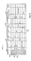
- FIG. 8 depicts a selection matrix 600 that may be used to select or designate a specific transition for any combination of screen class in accordance with an embodiment of the present invention.
- the row 602 and the column 604 of the matrix 600 depict the nine screen classes discussed above as included in one embodiment of the present invention.
- the cells of row 602 may represent an entering or target screen, and the cells of column 604 may represent an exiting or previous screen.
- Each cell in the matrix 600 where a screen class from row 602 and a screen class from column 604 intersect indicate the specific transition that may be used.
- no transition is present as there is no need to transition between identical screen classes.
- different combinations of screen classes may have specified transition effects and types. For example, if the exiting or previous screen is classified background-full, as in block 610 , and the entering screen is classified as menu-half, such as block 612 , the transition selected is a slide. Thus, the entering screen, classified as a menu-half screen, will slide into the exiting screen, classified as a background-full screen. In another example, if the entering screen is a menu showcase, as in block 614 , and exiting screen is classified as a foreground-full class, as in block 616 , then the selected transition is a fade. Thus, for that transition, a menu showcase screen will fade in over a fading out foreground-full screen.
- a pair of screen classes may have different transitions designated for the pair, depending on the direction of the transition. For example transitioning from a foreground-full screen class to a menu showcase screen class may be accomplished with a fade transition however, transitioning from the menu showcase screen class to the foreground-full screen class may be accomplished with a sliding transition.
- no specific transition may be specified, such as in cells 618 .
- a default transition may be used. If during the selection process, no transition is found in the selection matrix 600 , the default or fallback transition will be used.
- the matrix 600 may be pre-populated during the design of the user interface or the matrix 600 may be populated or changed according to user preferences, allowing users to specify their preferred transitions. Alternatively, multiple selection matrices may be used, such as one for pre-populated selections, one for user preferred selections, one for further subclasses of screens, etc.
- menus may be one of the possible elements displayed in the user interface 20 .
- screens displayed in the user interface 20 may include menus, in which each menu may comprise a list of items.
- Each list item may have a particular layout associated with that item, such that the layout specifies the position, size, and other properties of those components of the list item.
- FIG. 9 depicts a simplified menu screen 700 of a user interface 20 showing a list of items.
- These list items may represent items selectable by the user or may also be items used to display information that are not selectable. Additionally, as will be discussed below, the items may include static or dynamic components.
- this item includes text 706 shown as “TEXT1.”
- the second item 704 in the list of the menu screen 700 includes text 705 displayed as “TEXT2.”
- both items 702 and 704 include only text items, and a stored layout for those items need only store the layout of the text.
- the third item 706 includes both the text 707 , displayed as “TEXT3,” and a graphic 708 , such as a bitmap, as illustrated by the arrow.
- the layout for item 706 may store the position, size, and other properties of the text and the graphic 708 .
- the fourth item 710 in the list includes the text 711 (“TEXT4”), a graphic 712 represented by the arrow, and a dynamic, i.e. known only at runtime, item 714 . Therefore, the layout for the item 710 may need to include the position, size, and other properties of the text 711 , the graphic 712 , and the dynamic item 714 .
- FIG. 10 depicts a block diagram 800 showing a classification of list item layouts in accordance with an embodiment of the present technique that minimizes the memory usage of those list item layouts.
- the top of the block diagram 800 is a list view 802 .
- Underneath the list view 802 is a list child view 804 that contains the list item layouts 805 . All the possible list item layouts may be determined, and these are identified in FIG. 10 as layout 1 806 , layout 2 808 , layout 3 810 , and so on through layout “n” 812 .
- Each list item layout includes layout information for list item elements.
- layout 1 806 may include layout information for a text view 814 and a bitmap 816 .
- Layout 2 808 may include layout information for text view 818 only, whereas layout 3 810 may include that information for a text view 820 and a bitmap 822 .
- layouts may be specified for various elements of the list items, so that the list items may be displayed such as in the embodiment depicted in FIG. 9 .
- list items may be associated with layouts dynamically at the time a list item is rendered.
- the renderer for a list item can request a layout from software, such as from a model.
- the model can return a layout to the renderer, and the list item will use that layout.
- the layout can be dynamically based on a status, condition, or other data. For example, if a media file stored on the device 10 has not been played by a user, at the time the list item is rendered a list item may use layout 1 806 . If the media file stored on the device 10 has already been played by a user, then at the time the list item is rendered, the same list item may use layout 3 810 .
- list item layouts may be defined inside an object 826 .
- the object may be a flyweight object, wherein the flyweight object is shared among multiple contexts simultaneously. In each context, the flyweight object acts as an independent object, may be used the same as an instance of an independent object.
- the flyweight object 826 minimizes the total memory usage of storing a layout, and allows any number of items with the same layout to share the memory cost of the layout. Further, dynamic list items may be displayed, next to static list items.
- a menu list item that includes a text view and a bitmap may refer to the layout 1 806 for layout information.
- a second menu list item that includes a text view and a bitmap may also refer to layout 1 806 for layout information.
- list items instead of storing a list item layout for each list item, list items may refer to the same layout information stored in the flyweight object 826 . Further, because all possible list item layouts for the device 10 may be determined and stored in the flyweight object 826 , any list item may refer to the layouts in the flyweight object to obtain layout information.
Abstract
Description
Claims (23)
Priority Applications (1)
| Application Number | Priority Date | Filing Date | Title |
|---|---|---|---|
| US11/899,026 US8884981B2 (en) | 2007-09-04 | 2007-09-04 | Dynamically reconfigurable graphics layer system and method |
Applications Claiming Priority (1)
| Application Number | Priority Date | Filing Date | Title |
|---|---|---|---|
| US11/899,026 US8884981B2 (en) | 2007-09-04 | 2007-09-04 | Dynamically reconfigurable graphics layer system and method |
Publications (2)
| Publication Number | Publication Date |
|---|---|
| US20090058872A1 US20090058872A1 (en) | 2009-03-05 |
| US8884981B2 true US8884981B2 (en) | 2014-11-11 |
Family
ID=40406725
Family Applications (1)
| Application Number | Title | Priority Date | Filing Date |
|---|---|---|---|
| US11/899,026 Active 2031-02-05 US8884981B2 (en) | 2007-09-04 | 2007-09-04 | Dynamically reconfigurable graphics layer system and method |
Country Status (1)
| Country | Link |
|---|---|
| US (1) | US8884981B2 (en) |
Cited By (1)
| Publication number | Priority date | Publication date | Assignee | Title |
|---|---|---|---|---|
| US20180260095A1 (en) * | 2017-03-10 | 2018-09-13 | Guangdong Oppo Mobile Telecommunications Corp., Ltd. | Mobile terminal and method and device for controlling to display in the same |
Families Citing this family (9)
| Publication number | Priority date | Publication date | Assignee | Title |
|---|---|---|---|---|
| US7996666B2 (en) * | 2007-09-04 | 2011-08-09 | Apple Inc. | User influenced loading sequence of startup applications |
| KR20100045188A (en) * | 2008-10-23 | 2010-05-03 | 삼성전자주식회사 | Remote control device and method for controlling other devices using the remote control device |
| US8819570B2 (en) * | 2009-03-27 | 2014-08-26 | Zumobi, Inc | Systems, methods, and computer program products displaying interactive elements on a canvas |
| US8949734B2 (en) * | 2010-01-04 | 2015-02-03 | Verizon Patent And Licensing Inc. | Mobile device color-based content mapping and navigation |
| US8903366B2 (en) * | 2010-03-01 | 2014-12-02 | Samsung Electronics Co., Ltd. | Dynamic switching between software and hardware graphics rendering for power consumption |
| CN102339197A (en) * | 2010-07-26 | 2012-02-01 | 鸿富锦精密工业(深圳)有限公司 | Embedded system with date and time adjustment function and method for adjusting date and time |
| US8047974B1 (en) * | 2010-08-03 | 2011-11-01 | Kanelos Stephen A | Exercise apparatus and methods of assembling and using the same |
| US9235318B2 (en) * | 2012-02-01 | 2016-01-12 | Facebook, Inc. | Transitions among hierarchical user-interface layers |
| AU2016296471B2 (en) * | 2015-07-17 | 2021-10-28 | Crown Equipment Corporation | Processing device having a graphical user interface for industrial vehicle |
Citations (56)
| Publication number | Priority date | Publication date | Assignee | Title |
|---|---|---|---|---|
| US5379057A (en) | 1988-11-14 | 1995-01-03 | Microslate, Inc. | Portable computer with touch screen and computer system employing same |
| US5655126A (en) * | 1994-02-23 | 1997-08-05 | Sun Microsystems, Inc. | Method & apparatus for a power management pseudo-device driver |
| US5790134A (en) * | 1995-03-06 | 1998-08-04 | Seiko Epson Corporation | Hardware architecture for image generation and manipulation |
| US5977977A (en) * | 1995-08-04 | 1999-11-02 | Microsoft Corporation | Method and system for multi-pass rendering |
| US5986667A (en) * | 1994-12-22 | 1999-11-16 | Apple Computer, Inc. | Mechanism for rendering scenes using an object drawing subsystem |
| US6009256A (en) * | 1997-05-02 | 1999-12-28 | Axis Systems, Inc. | Simulation/emulation system and method |
| US6016151A (en) * | 1997-09-12 | 2000-01-18 | Neomagic Corp. | 3D triangle rendering by texture hardware and color software using simultaneous triangle-walking and interpolation for parallel operation |
| US6044408A (en) * | 1996-04-25 | 2000-03-28 | Microsoft Corporation | Multimedia device interface for retrieving and exploiting software and hardware capabilities |
| US6188975B1 (en) * | 1998-03-31 | 2001-02-13 | Synopsys, Inc. | Programmatic use of software debugging to redirect hardware related operations to a hardware simulator |
| US6212489B1 (en) * | 1996-05-14 | 2001-04-03 | Mentor Graphics Corporation | Optimizing hardware and software co-verification system |
| US6356862B2 (en) * | 1998-09-24 | 2002-03-12 | Brian Bailey | Hardware and software co-verification employing deferred synchronization |
| US6389379B1 (en) * | 1997-05-02 | 2002-05-14 | Axis Systems, Inc. | Converification system and method |
| US6415384B1 (en) * | 1998-10-30 | 2002-07-02 | Lucent Technologies Inc. | Hardware/software co-synthesis of dynamically reconfigurable embedded systems |
| US20020163540A1 (en) * | 2001-05-01 | 2002-11-07 | Matsushita Electric Industrial Co., Ltd. | GUI display processor |
| US20030043191A1 (en) * | 2001-08-17 | 2003-03-06 | David Tinsley | Systems and methods for displaying a graphical user interface |
| US6578197B1 (en) * | 1998-04-08 | 2003-06-10 | Silicon Graphics, Inc. | System and method for high-speed execution of graphics application programs including shading language instructions |
| US20030169279A1 (en) * | 2002-03-05 | 2003-09-11 | Oberoi Ranjit S. | Reconfigurable pixel computation unit |
| US6622287B1 (en) * | 2000-03-08 | 2003-09-16 | Nec Corporation | Low power hardware/software partitioning approach for core-based embedded systems |
| US20030184593A1 (en) * | 2001-10-09 | 2003-10-02 | Andrew Dunlop | System, method and article of manufacture for a user interface for an MP3 audio player |
| US20030187662A1 (en) * | 2001-10-04 | 2003-10-02 | Alex Wilson | System, method, and article of manufacture for a reconfigurable hardware-based audio decoder |
| US6636214B1 (en) * | 2000-08-23 | 2003-10-21 | Nintendo Co., Ltd. | Method and apparatus for dynamically reconfiguring the order of hidden surface processing based on rendering mode |
| US20040039862A1 (en) * | 2002-08-08 | 2004-02-26 | Hunt Peter D. | System and method of switching between multiple viewing modes in a multi-head computer system |
| US6856951B2 (en) * | 2002-11-15 | 2005-02-15 | Rajat Moona | Repartitioning performance estimation in a hardware-software system |
| US20050231516A1 (en) * | 2004-04-16 | 2005-10-20 | Apple Computer, Inc. | System and method for processing graphics operations with graphics processing unit |
| US20050285965A1 (en) | 2004-06-24 | 2005-12-29 | Apple Computer, Inc. | User-interface design |
| US7002599B2 (en) * | 2002-07-26 | 2006-02-21 | Sun Microsystems, Inc. | Method and apparatus for hardware acceleration of clipping and graphical fill in display systems |
| US20060048164A1 (en) * | 2004-08-30 | 2006-03-02 | Darrin Fry | Method and system for providing transparent access to hardware graphic layers |
| US20060139369A1 (en) | 2004-12-23 | 2006-06-29 | Apple Computer, Inc. | Manipulating text and graphic appearance |
| US7146581B2 (en) * | 2002-11-15 | 2006-12-05 | Russell Alan Klein | Automated repartitioning of hardware and software components in an embedded system |
| US20060290703A1 (en) * | 2005-06-24 | 2006-12-28 | Microsoft Corporation | Non-destructive processing of digital image data |
| US20070028023A1 (en) * | 2005-07-26 | 2007-02-01 | Arad Rostampour | Supporting multiple methods for device hotplug in a single computer |
| US20070038939A1 (en) * | 2005-07-11 | 2007-02-15 | Challen Richard F | Display servers and systems and methods of graphical display |
| US7209146B2 (en) | 2003-08-01 | 2007-04-24 | Apple Inc. | Methods and apparatuses for the automated display of visual effects |
| US7230626B2 (en) * | 2001-01-16 | 2007-06-12 | Microsoft Corp. | System and method for optimizing a graphics intensive software program for the user's graphics hardware |
| US20070150589A1 (en) * | 2005-12-08 | 2007-06-28 | Kim Won T | Context-awareness based system supporting autonomous system construction and method of operating the system |
| US20070182747A1 (en) * | 2004-04-16 | 2007-08-09 | John Harper | High-level program interface for graphics operations |
| US7281248B2 (en) * | 2002-11-19 | 2007-10-09 | Microsoft Corporation | Virtualized and realized user interface controls |
| US7286140B2 (en) * | 2002-07-26 | 2007-10-23 | Sun Microsystems, Inc. | Hardware acceleration of display data clipping |
| US7302689B2 (en) * | 2000-12-06 | 2007-11-27 | Microsoft Corporation | System and related interfaces supporting the processing of media content |
| US20070288856A1 (en) * | 2004-02-19 | 2007-12-13 | Butlin Stefan G | Layered User Interface |
| US20080016491A1 (en) * | 2006-07-13 | 2008-01-17 | Apple Computer, Inc | Multimedia scripting |
| US7356672B2 (en) * | 2004-05-28 | 2008-04-08 | The Regents Of The University Of California | Warp processor for dynamic hardware/software partitioning |
| US7366921B2 (en) * | 2004-04-23 | 2008-04-29 | Hewlett-Packard Development Company, L.P. | Selecting input/output devices to control power consumption of a computer system |
| US20080117204A1 (en) * | 2006-11-22 | 2008-05-22 | Matthias Thorn | Rendering performance regulator |
| US7395521B1 (en) * | 2005-10-14 | 2008-07-01 | Xilinx, Inc. | Method and apparatus for translating an imperative programming language description of a circuit into a hardware description |
| US7511718B2 (en) * | 2003-10-23 | 2009-03-31 | Microsoft Corporation | Media integration layer |
| US7571385B2 (en) * | 2000-12-06 | 2009-08-04 | Microsoft Corporation | Methods and systems for processing media content |
| US7623140B1 (en) * | 1999-03-05 | 2009-11-24 | Zoran Corporation | Method and apparatus for processing video and graphics data to create a composite output image having independent and separate layers of video and graphics |
| US7631319B2 (en) * | 2000-12-06 | 2009-12-08 | Microsoft Corporation | System and related methods for reducing source filter invocation in a development project |
| US7680898B2 (en) * | 2000-12-06 | 2010-03-16 | Microsoft Corporation | Systems for processing multi-media editing projects |
| US7814432B2 (en) * | 1996-05-10 | 2010-10-12 | Apple, Inc. | Method and system for image rendering including polymorphic image data in a graphical user interface |
| US7831805B2 (en) * | 2004-01-15 | 2010-11-09 | International Business Machines Corporation | Coupling a general purpose processor to an application specific instruction set processor |
| US7844915B2 (en) * | 2007-01-07 | 2010-11-30 | Apple Inc. | Application programming interfaces for scrolling operations |
| US7903115B2 (en) * | 2007-01-07 | 2011-03-08 | Apple Inc. | Animations |
| US8069436B2 (en) * | 2004-08-13 | 2011-11-29 | Cypress Semiconductor Corporation | Providing hardware independence to automate code generation of processing device firmware |
| US8196044B2 (en) * | 2004-01-05 | 2012-06-05 | Microsoft Corporation | Configuration of user interfaces |
-
2007
- 2007-09-04 US US11/899,026 patent/US8884981B2/en active Active
Patent Citations (61)
| Publication number | Priority date | Publication date | Assignee | Title |
|---|---|---|---|---|
| US5379057A (en) | 1988-11-14 | 1995-01-03 | Microslate, Inc. | Portable computer with touch screen and computer system employing same |
| US5675362A (en) | 1988-11-14 | 1997-10-07 | Microslate, Inc. | Portable computer with touch screen and computing system employing same |
| US5655126A (en) * | 1994-02-23 | 1997-08-05 | Sun Microsystems, Inc. | Method & apparatus for a power management pseudo-device driver |
| US5986667A (en) * | 1994-12-22 | 1999-11-16 | Apple Computer, Inc. | Mechanism for rendering scenes using an object drawing subsystem |
| US5790134A (en) * | 1995-03-06 | 1998-08-04 | Seiko Epson Corporation | Hardware architecture for image generation and manipulation |
| US5977977A (en) * | 1995-08-04 | 1999-11-02 | Microsoft Corporation | Method and system for multi-pass rendering |
| US6044408A (en) * | 1996-04-25 | 2000-03-28 | Microsoft Corporation | Multimedia device interface for retrieving and exploiting software and hardware capabilities |
| US7814432B2 (en) * | 1996-05-10 | 2010-10-12 | Apple, Inc. | Method and system for image rendering including polymorphic image data in a graphical user interface |
| US6212489B1 (en) * | 1996-05-14 | 2001-04-03 | Mentor Graphics Corporation | Optimizing hardware and software co-verification system |
| US6389379B1 (en) * | 1997-05-02 | 2002-05-14 | Axis Systems, Inc. | Converification system and method |
| US6009256A (en) * | 1997-05-02 | 1999-12-28 | Axis Systems, Inc. | Simulation/emulation system and method |
| US6016151A (en) * | 1997-09-12 | 2000-01-18 | Neomagic Corp. | 3D triangle rendering by texture hardware and color software using simultaneous triangle-walking and interpolation for parallel operation |
| US6188975B1 (en) * | 1998-03-31 | 2001-02-13 | Synopsys, Inc. | Programmatic use of software debugging to redirect hardware related operations to a hardware simulator |
| US6578197B1 (en) * | 1998-04-08 | 2003-06-10 | Silicon Graphics, Inc. | System and method for high-speed execution of graphics application programs including shading language instructions |
| US6356862B2 (en) * | 1998-09-24 | 2002-03-12 | Brian Bailey | Hardware and software co-verification employing deferred synchronization |
| US6415384B1 (en) * | 1998-10-30 | 2002-07-02 | Lucent Technologies Inc. | Hardware/software co-synthesis of dynamically reconfigurable embedded systems |
| US7623140B1 (en) * | 1999-03-05 | 2009-11-24 | Zoran Corporation | Method and apparatus for processing video and graphics data to create a composite output image having independent and separate layers of video and graphics |
| US6622287B1 (en) * | 2000-03-08 | 2003-09-16 | Nec Corporation | Low power hardware/software partitioning approach for core-based embedded systems |
| US6636214B1 (en) * | 2000-08-23 | 2003-10-21 | Nintendo Co., Ltd. | Method and apparatus for dynamically reconfiguring the order of hidden surface processing based on rendering mode |
| US7680898B2 (en) * | 2000-12-06 | 2010-03-16 | Microsoft Corporation | Systems for processing multi-media editing projects |
| US7631319B2 (en) * | 2000-12-06 | 2009-12-08 | Microsoft Corporation | System and related methods for reducing source filter invocation in a development project |
| US7571385B2 (en) * | 2000-12-06 | 2009-08-04 | Microsoft Corporation | Methods and systems for processing media content |
| US7302689B2 (en) * | 2000-12-06 | 2007-11-27 | Microsoft Corporation | System and related interfaces supporting the processing of media content |
| US7757240B2 (en) * | 2000-12-06 | 2010-07-13 | Microsoft Corporation | System and related interfaces supporting the processing of media content |
| US7230626B2 (en) * | 2001-01-16 | 2007-06-12 | Microsoft Corp. | System and method for optimizing a graphics intensive software program for the user's graphics hardware |
| US20020163540A1 (en) * | 2001-05-01 | 2002-11-07 | Matsushita Electric Industrial Co., Ltd. | GUI display processor |
| US20030043191A1 (en) * | 2001-08-17 | 2003-03-06 | David Tinsley | Systems and methods for displaying a graphical user interface |
| US20030187662A1 (en) * | 2001-10-04 | 2003-10-02 | Alex Wilson | System, method, and article of manufacture for a reconfigurable hardware-based audio decoder |
| US20030184593A1 (en) * | 2001-10-09 | 2003-10-02 | Andrew Dunlop | System, method and article of manufacture for a user interface for an MP3 audio player |
| US20030169279A1 (en) * | 2002-03-05 | 2003-09-11 | Oberoi Ranjit S. | Reconfigurable pixel computation unit |
| US7286140B2 (en) * | 2002-07-26 | 2007-10-23 | Sun Microsystems, Inc. | Hardware acceleration of display data clipping |
| US7002599B2 (en) * | 2002-07-26 | 2006-02-21 | Sun Microsystems, Inc. | Method and apparatus for hardware acceleration of clipping and graphical fill in display systems |
| US20040039862A1 (en) * | 2002-08-08 | 2004-02-26 | Hunt Peter D. | System and method of switching between multiple viewing modes in a multi-head computer system |
| US7952569B2 (en) * | 2002-08-08 | 2011-05-31 | Hewlett-Packard Development Company, L.P. | System and method of switching between multiple viewing modes in a multi-head computer system |
| US7146581B2 (en) * | 2002-11-15 | 2006-12-05 | Russell Alan Klein | Automated repartitioning of hardware and software components in an embedded system |
| US6856951B2 (en) * | 2002-11-15 | 2005-02-15 | Rajat Moona | Repartitioning performance estimation in a hardware-software system |
| US7281248B2 (en) * | 2002-11-19 | 2007-10-09 | Microsoft Corporation | Virtualized and realized user interface controls |
| US7209146B2 (en) | 2003-08-01 | 2007-04-24 | Apple Inc. | Methods and apparatuses for the automated display of visual effects |
| US7511718B2 (en) * | 2003-10-23 | 2009-03-31 | Microsoft Corporation | Media integration layer |
| US8196044B2 (en) * | 2004-01-05 | 2012-06-05 | Microsoft Corporation | Configuration of user interfaces |
| US7831805B2 (en) * | 2004-01-15 | 2010-11-09 | International Business Machines Corporation | Coupling a general purpose processor to an application specific instruction set processor |
| US20070288856A1 (en) * | 2004-02-19 | 2007-12-13 | Butlin Stefan G | Layered User Interface |
| US20070247468A1 (en) * | 2004-04-16 | 2007-10-25 | Mark Zimmer | System and method for processing graphics operations with graphics processing unit |
| US20050231516A1 (en) * | 2004-04-16 | 2005-10-20 | Apple Computer, Inc. | System and method for processing graphics operations with graphics processing unit |
| US20070182747A1 (en) * | 2004-04-16 | 2007-08-09 | John Harper | High-level program interface for graphics operations |
| US7366921B2 (en) * | 2004-04-23 | 2008-04-29 | Hewlett-Packard Development Company, L.P. | Selecting input/output devices to control power consumption of a computer system |
| US7356672B2 (en) * | 2004-05-28 | 2008-04-08 | The Regents Of The University Of California | Warp processor for dynamic hardware/software partitioning |
| US20050285965A1 (en) | 2004-06-24 | 2005-12-29 | Apple Computer, Inc. | User-interface design |
| US8069436B2 (en) * | 2004-08-13 | 2011-11-29 | Cypress Semiconductor Corporation | Providing hardware independence to automate code generation of processing device firmware |
| US20060048164A1 (en) * | 2004-08-30 | 2006-03-02 | Darrin Fry | Method and system for providing transparent access to hardware graphic layers |
| US7830372B2 (en) * | 2004-08-30 | 2010-11-09 | Qnx Software Systems Gmbh & Co. Kg | Method and system for providing transparent access to hardware graphic layers |
| US20060139369A1 (en) | 2004-12-23 | 2006-06-29 | Apple Computer, Inc. | Manipulating text and graphic appearance |
| US20060290703A1 (en) * | 2005-06-24 | 2006-12-28 | Microsoft Corporation | Non-destructive processing of digital image data |
| US20070038939A1 (en) * | 2005-07-11 | 2007-02-15 | Challen Richard F | Display servers and systems and methods of graphical display |
| US20070028023A1 (en) * | 2005-07-26 | 2007-02-01 | Arad Rostampour | Supporting multiple methods for device hotplug in a single computer |
| US7395521B1 (en) * | 2005-10-14 | 2008-07-01 | Xilinx, Inc. | Method and apparatus for translating an imperative programming language description of a circuit into a hardware description |
| US20070150589A1 (en) * | 2005-12-08 | 2007-06-28 | Kim Won T | Context-awareness based system supporting autonomous system construction and method of operating the system |
| US20080016491A1 (en) * | 2006-07-13 | 2008-01-17 | Apple Computer, Inc | Multimedia scripting |
| US20080117204A1 (en) * | 2006-11-22 | 2008-05-22 | Matthias Thorn | Rendering performance regulator |
| US7844915B2 (en) * | 2007-01-07 | 2010-11-30 | Apple Inc. | Application programming interfaces for scrolling operations |
| US7903115B2 (en) * | 2007-01-07 | 2011-03-08 | Apple Inc. | Animations |
Non-Patent Citations (2)
| Title |
|---|
| Masso' et al., Direct Manipulation of User Interfaces for Migration, Iui 2006, Jan. 29-Feb. 1, 2006, Acm, pp. 140-147. * |
| Styles et al., Proceedings from the 2000 IEEE Symposium on Field-Programmable Custom Computing Machines, Apr. 17, 2000-Apr. 19, 2000, pp. 77-87. * |
Cited By (2)
| Publication number | Priority date | Publication date | Assignee | Title |
|---|---|---|---|---|
| US20180260095A1 (en) * | 2017-03-10 | 2018-09-13 | Guangdong Oppo Mobile Telecommunications Corp., Ltd. | Mobile terminal and method and device for controlling to display in the same |
| US10564837B2 (en) * | 2017-03-10 | 2020-02-18 | Guangdong Oppo Mobile Telecommunications Corp., Ltd. | Mobile terminal and method and device for controlling to display in the same |
Also Published As
| Publication number | Publication date |
|---|---|
| US20090058872A1 (en) | 2009-03-05 |
Similar Documents
| Publication | Publication Date | Title |
|---|---|---|
| US7810047B2 (en) | List item layouts system and method | |
| US7917861B2 (en) | User interface elements cloning and transitions | |
| US8884981B2 (en) | Dynamically reconfigurable graphics layer system and method | |
| US8201102B2 (en) | Opaque views for graphical user interfaces | |
| US10613701B2 (en) | Customizable bladed applications | |
| EP2360569B1 (en) | Method and apparatus for providing informations of multiple applications | |
| US8832575B2 (en) | Speed dependent displaying of information items in a graphical user interface | |
| KR101961860B1 (en) | User terminal apparatus and contol method thereof | |
| EP3324279B1 (en) | Selective hibernation of activities in an electronic device | |
| CN108351706A (en) | Electronic equipment with rollable display and its control method | |
| US20090064045A1 (en) | Low memory rendering of graphical objects | |
| CN105302418A (en) | Information processing method and electronic device | |
| US20220253207A1 (en) | Display method and electronic device | |
| JP2014106882A (en) | Information processing device and display control method | |
| CN103092327B (en) | Subscriber equipment and display packing thereof | |
| EP3396519A1 (en) | Terminal and display control method | |
| WO2013182089A1 (en) | Object suspension realizing method and device | |
| WO2023061280A1 (en) | Application program display method and apparatus, and electronic device | |
| US11086489B2 (en) | Information processing device and information processing method for moving or advancing a display region | |
| CN108549575A (en) | Exit processing method, device, storage medium and the electronic equipment of split screen | |
| WO2023155836A1 (en) | Display method and apparatus, and electronic device and readable storage medium | |
| KR101196742B1 (en) | Method for hierarchical user interface using multi demensional graphic in mobile communication terminal | |
| CN105808379A (en) | Terminal backup method and terminal | |
| WO2021253922A1 (en) | Font switching method and electronic device | |
| KR101839408B1 (en) | Extensible multiple transparent display apparatus, control method thereof and recording medium for performing the method |
Legal Events
| Date | Code | Title | Description |
|---|---|---|---|
| AS | Assignment |
Owner name: APPLE INC., CALIFORNIA Free format text: ASSIGNMENT OF ASSIGNORS INTEREST;ASSIGNORS:BOETTCHER, JESSE W.;HUANG, SZU-WEN;AUKAROGULLARI, GOKHAN;REEL/FRAME:019838/0924;SIGNING DATES FROM 20070830 TO 20070831 Owner name: APPLE INC., CALIFORNIA Free format text: ASSIGNMENT OF ASSIGNORS INTEREST;ASSIGNORS:BOETTCHER, JESSE W.;HUANG, SZU-WEN;AUKAROGULLARI, GOKHAN;SIGNING DATES FROM 20070830 TO 20070831;REEL/FRAME:019838/0924 |
|
| AS | Assignment |
Owner name: APPLE INC., CALIFORNIA Free format text: CORRECTIVE COVERSHEET TO CORRECT THE NAME OF THE ASSIGNOR THAT WAS PREVIOUSLY RECORDED ON REEL 019838, FRAME 0924.;ASSIGNORS:BOETTCHER, JESSE W.;HUANG, SZU-WEN;AVKAROGULLARI, GOKHAN;REEL/FRAME:020046/0148;SIGNING DATES FROM 20070830 TO 20070831 Owner name: APPLE INC., CALIFORNIA Free format text: CORRECTIVE COVERSHEET TO CORRECT THE NAME OF THE ASSIGNOR THAT WAS PREVIOUSLY RECORDED ON REEL 019838, FRAME 0924;ASSIGNORS:BOETTCHER, JESSE W.;HUANG, SZU-WEN;AVKAROGULLARI, GOKHAN;SIGNING DATES FROM 20070830 TO 20070831;REEL/FRAME:020046/0148 |
|
| AS | Assignment |
Owner name: APPLE INC., CALIFORNIA Free format text: ASSIGNMENT OF ASSIGNORS INTEREST;ASSIGNORS:BOETTCHER, JESSE W.;HUANG, SZU-WEN;AVKAROGULLARI, GOKHAN;REEL/FRAME:021856/0154;SIGNING DATES FROM 20080922 TO 20081105 Owner name: APPLE INC., CALIFORNIA Free format text: ASSIGNMENT OF ASSIGNORS INTEREST;ASSIGNORS:BOETTCHER, JESSE W.;HUANG, SZU-WEN;AVKAROGULLARI, GOKHAN;SIGNING DATES FROM 20080922 TO 20081105;REEL/FRAME:021856/0154 |
|
| FEPP | Fee payment procedure |
Free format text: PAYOR NUMBER ASSIGNED (ORIGINAL EVENT CODE: ASPN); ENTITY STATUS OF PATENT OWNER: LARGE ENTITY |
|
| STCF | Information on status: patent grant |
Free format text: PATENTED CASE |
|
| MAFP | Maintenance fee payment |
Free format text: PAYMENT OF MAINTENANCE FEE, 4TH YEAR, LARGE ENTITY (ORIGINAL EVENT CODE: M1551) Year of fee payment: 4 |
|
| MAFP | Maintenance fee payment |
Free format text: PAYMENT OF MAINTENANCE FEE, 8TH YEAR, LARGE ENTITY (ORIGINAL EVENT CODE: M1552); ENTITY STATUS OF PATENT OWNER: LARGE ENTITY Year of fee payment: 8 |