US8891626B1 - Center of motion for encoding motion fields - Google Patents
Center of motion for encoding motion fields Download PDFInfo
- Publication number
- US8891626B1 US8891626B1 US13/080,266 US201113080266A US8891626B1 US 8891626 B1 US8891626 B1 US 8891626B1 US 201113080266 A US201113080266 A US 201113080266A US 8891626 B1 US8891626 B1 US 8891626B1
- Authority
- US
- United States
- Prior art keywords
- motion
- field
- block
- motion vector
- frame
- Prior art date
- Legal status (The legal status is an assumption and is not a legal conclusion. Google has not performed a legal analysis and makes no representation as to the accuracy of the status listed.)
- Active, expires
Links
Images


Classifications
-
- H—ELECTRICITY
- H04—ELECTRIC COMMUNICATION TECHNIQUE
- H04N—PICTORIAL COMMUNICATION, e.g. TELEVISION
- H04N19/00—Methods or arrangements for coding, decoding, compressing or decompressing digital video signals
- H04N19/50—Methods or arrangements for coding, decoding, compressing or decompressing digital video signals using predictive coding
- H04N19/503—Methods or arrangements for coding, decoding, compressing or decompressing digital video signals using predictive coding involving temporal prediction
- H04N19/51—Motion estimation or motion compensation
- H04N19/573—Motion compensation with multiple frame prediction using two or more reference frames in a given prediction direction
-
- H—ELECTRICITY
- H04—ELECTRIC COMMUNICATION TECHNIQUE
- H04N—PICTORIAL COMMUNICATION, e.g. TELEVISION
- H04N19/00—Methods or arrangements for coding, decoding, compressing or decompressing digital video signals
- H04N19/10—Methods or arrangements for coding, decoding, compressing or decompressing digital video signals using adaptive coding
- H04N19/134—Methods or arrangements for coding, decoding, compressing or decompressing digital video signals using adaptive coding characterised by the element, parameter or criterion affecting or controlling the adaptive coding
- H04N19/136—Incoming video signal characteristics or properties
- H04N19/137—Motion inside a coding unit, e.g. average field, frame or block difference
-
- H—ELECTRICITY
- H04—ELECTRIC COMMUNICATION TECHNIQUE
- H04N—PICTORIAL COMMUNICATION, e.g. TELEVISION
- H04N19/00—Methods or arrangements for coding, decoding, compressing or decompressing digital video signals
- H04N19/50—Methods or arrangements for coding, decoding, compressing or decompressing digital video signals using predictive coding
- H04N19/503—Methods or arrangements for coding, decoding, compressing or decompressing digital video signals using predictive coding involving temporal prediction
- H04N19/51—Motion estimation or motion compensation
- H04N19/513—Processing of motion vectors
- H04N19/521—Processing of motion vectors for estimating the reliability of the determined motion vectors or motion vector field, e.g. for smoothing the motion vector field or for correcting motion vectors
Definitions
- the present invention relates in general to video encoding and decoding.
- VPx a standard promulgated by Google Inc. of Mountain View, Calif.
- H.264 a standard promulgated by ITU-T Video Coding Experts Group (VCEG) and the ISO/IEC Moving Picture Experts Group (MPEG), including present and future versions thereof.
- VCEG Video Coding Experts Group
- MPEG Moving Picture Experts Group
- H.264 is also known as MPEG-4 Part 10 or MPEG-4 AVC (formally, ISO/IEC 14496-10).
- a method for encoding a video signal having a plurality of frames including blocks each having pixels comprises determining a motion field for a plurality of pixels in a first frame having a same direction of movement as each other, the motion field having a field center of motion, at least one dimension defining a shape of the motion field and a field motion vector, encoding the motion field into a bitstream, associating at least one block of the first frame with the motion field and encoding each block associated with the motion field into the bitstream without a separate motion vector.
- Determining the motion field includes determining a motion vector for each of a plurality of blocks of the first frame, grouping the motion vectors for each of the plurality of blocks of the first frame into a plurality of groups based on a proximity of respective ones of the plurality of blocks to others having the same motion vector and calculating the field center of motion and the at least one dimension defining the shape of the motion field using dimensions of the plurality of blocks forming a group of the plurality of groups.
- Another aspect of the disclosed embodiments includes a method for decoding a video signal having a plurality of frames including blocks containing pixels.
- This method comprises decoding a plurality of motion fields received from a bitstream, each of the plurality of motion fields having a field center of motion, at least one dimension defining a shape of the motion field and a field motion vector, receiving a block from the bitstream, the block comprising a plurality of pixels of a first frame, comparing a position of the block with each of the plurality of motion fields, and setting a motion vector of the block to the field motion vector of one of the plurality of motion fields where the position of the block is within the shape of the one of the plurality of motion fields.
- An apparatus for encoding a video signal having a plurality of frames including blocks each having pixels comprises a memory and a processor configured to execute instructions stored in the memory to determine a motion field for a plurality of pixels in a first frame having a same direction of movement as each other, the motion field having a field center of motion, at least one dimension defining a shape of the motion field and a field motion vector, by determining a motion vector for each of a plurality of blocks of the first frame, grouping the motion vectors for each of the plurality of blocks of the first frame into a plurality of groups based on a proximity of respective ones of the plurality of blocks to others having the same motion vector, and calculating the field center of motion and the at least one dimension defining the shape of the motion field using dimensions of the plurality of blocks forming a group of the plurality of groups.
- the processor of this aspect is also configured to encode the motion field into a bitstream, associate at least one block of the first frame with the motion field and encode each block associated with the
- FIG. 1 Another aspect of embodiments described herein includes an apparatus for encoding a video signal having a plurality of frames including blocks containing pixels.
- This apparatus comprises means for determining a motion field for a plurality of pixels in a first frame having a same direction of movement as each other, the motion field having a field center of motion, at least one dimension defining a shape of the motion field and a field motion vector, means for encoding the motion field into a bitstream, means for associating at least one macroblock of the first frame with the motion field, and means for encoding each macroblock associated with the motion field into the bitstream without a separate motion vector.
- the determining means includes, in this aspect, means for determining a motion vector for each of a plurality of blocks of the first frame, means for grouping the motion vectors for each of the plurality of blocks of the first frame into a plurality of groups based on a proximity of respective ones of the plurality of blocks to others having the same motion vector, and means for calculating the field center of motion and the at least one dimension defining the shape of the motion field using dimensions of the plurality of blocks forming a group of the plurality of groups.
- FIG. 1 is a diagram of a video bitstream
- FIG. 2 is a block diagram of a video compression system in accordance with one embodiment
- FIG. 3 is a block diagram of a video decompression system in accordance with another embodiment
- FIGS. 4A and 4B include a flow chart illustrating an exemplary method of encoding motion fields for a first frame using the intra/inter prediction stage of the encoder shown in FIG. 2 ;
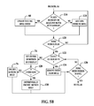
- FIGS. 5A and 5B include a flow chart illustrating an exemplary method of encoding motion fields for frames subsequent to a first frame using the intra/inter prediction stage of the encoder shown in FIG. 2 ;
- FIG. 6 is a block diagram illustrating the shift of a center of motion by its motion vector.
- FIG. 7 includes a flow chart illustrating an exemplary method of decoding motion fields for frames using the intra/inter prediction stage of the decoder shown in FIG. 3 .
- techniques described herein provide a method and system that re-uses motion vector information across multiple frames. By doing so, the techniques seek to decrease the number of bits spent to encode motion vector information, increasing the compression and reducing the amount of data requiring transmission to reconstruct a video stream for display.
- FIG. 1 is a diagram showing a typical video bitstream 10 to be encoded and decoded.
- Video coding formats such as VP8 or H.264, provide a defined hierarchy of layers for video stream 10 .
- the highest level in the layer is a video sequence 12 .
- video sequence 12 consists of a number of adjacent frames 14 , which can be further subdivided into a single frame 16 .
- frame 16 can be divided into a series of macroblocks 18 , which contain data corresponding to, for example, a 16 ⁇ 16 block of displayed pixels.
- Each macroblock 18 can contain luminance and chrominance data for the corresponding pixels, and they are generally although not necessarily fixed in size.
- Macroblocks 18 can also be of any other suitable size such as 16 ⁇ 8 or 8 ⁇ 16 pixel groups and can further be subdivided into smaller blocks depending on the application.
- FIG. 2 is a block diagram of a video compression system in accordance with one embodiment.
- An encoder 20 encodes an input video stream 10 .
- Encoder 20 in this example has the following stages to perform the various functions in a forward path (shown by the solid connection lines) to produce an encoded or compressed bitstream 24 : intra/inter prediction stage 26 , transform stage 28 , quantization stage 30 and entropy encoding stage 32 .
- Encoder 20 also includes a reconstruction path (shown by the dotted connection lines) to reconstruct a frame for encoding of further macroblocks.
- encoder 20 has the following stages to perform the various functions in the reconstruction path: dequantization stage 34 , inverse transform stage 36 , reconstruction stage 37 and loop filtering stage 38 .
- Other structural variations of encoder 20 can be used to encode bitstream 24 .
- each frame 16 within input video stream 10 is processed into units of macroblocks.
- each macroblock can be encoded using either an intra prediction or inter prediction mode. In either case, a prediction macroblock can be formed.
- a prediction macroblock can be formed from samples in the current frame that have been previously encoded and reconstructed.
- a prediction macroblock can be formed from samples in one or more constructed reference frames such as those describe in, for example, U.S. Patent Publication No. 2010-0061461 A1.
- the prediction macroblock can be subtracted from the current macroblock at stage 26 to produce a residual macroblock (residual).
- Transform stage 28 transform codes the residual, and quantization stage 30 quantizes the residual to provide a set of quantized transform coefficients.
- the quantized transform coefficients are then entropy coded by entropy encoding stage 32 .
- the entropy-coded coefficients, together with the information required to decode the macroblock, such as the type of prediction mode used, motion vectors and quantizer value, are then output to compressed bitstream 24 .
- the reconstruction path in FIG. 2 is present to ensure that both the encoder and the decoder use the same reference frames to decode the macroblocks.
- the reconstruction path performs functions that are similar to functions that take place during the decoding process that are discussed in more detail below, including dequantizing the transform coefficients at a dequantization stage 34 and inverse transforming the dequantized transform coefficients at an inverse transform stage 36 in order to produce a derivative residual macroblock (derivative residual).
- the prediction macroblock that was predicted at prediction stage 26 can be added to the derivative residual to create a reconstructed macroblock.
- a loop filter 38 can then be applied to the reconstructed macroblock to reduce blocking distortion.
- encoder 20 can be used to encode bitstream 24 as mentioned briefly above.
- a non-transform based encoder can quantize the residual signal directly without transform stage 29 .
- an encoder may have quantization stage 30 and dequantization stage 34 combined into a single stage.
- the encoding process shown in FIG. 2 can include two iterations or “passes” of processing the video data.
- the first pass can be carried out by encoder 20 using an encoding process that is less computationally intensive, and that gathers and stores information about input video stream 10 for use in the second pass.
- encoder 20 uses this information to optimize final encoding of input video stream 10 .
- encoder 20 may use this information to select parameters for encoding, locating key-frames and selecting coding modes used to encode macroblocks 18 and to allocate the number of bits to each frame.
- the output of the second pass can be final compressed bitstream 24 .
- the coding mode can be used to indicate which motion vector should be used for a block in the second pass. For example, the coding mode can indicate that a new motion vector should be calculated for the block. Alternatively, the coding mode can indicate that the motion vector belonging to a neighboring block should be used, or that no motion vector (i.e., a zero motion vector) should be used. Details of possible choices of motion vectors according to certain embodiments of the invention are described in additional detail hereinafter.
- FIG. 3 is a block diagram of a video decompression system or decoder 42 to decode compressed bitstream 24 .
- Decoder 42 similar to the reconstruction path of the encoder 20 discussed previously, can include the following stages to perform various functions to produce an output video stream 44 from compressed bitstream 24 : entropy decoding stage 46 , dequantization stage 48 , inverse transform stage 50 , intra/inter prediction stage 52 , reconstruction stage 54 , loop filter stage 56 and deblocking filtering stage 58 .
- Other structural variations of decoder 42 can be used to decode compressed bitstream 24 .
- bitstream 24 When compressed bitstream 24 is presented for decoding, the data elements within bitstream 24 can be entropy decoded by entropy decoding stage 46 (using for, for example, Context Adaptive Binary Arithmetic Coding) to produce a set of quantized transform coefficients.
- Dequantization stage 48 dequantizes the transform coefficients
- inverse transform stage 50 inverse transforms the dequantized transform coefficients to produce a derivative residual that can be identical to that created by the reconstruction stage in the encoder 20 .
- decoder 42 can use intra/inter prediction stage 52 to create the same prediction macroblock as was created in encoder 20 .
- the prediction macroblock can be added to the derivative residual to create a reconstructed macroblock.
- the loop filter 56 can be applied to the reconstructed macroblock to further reduce blocking artifacts.
- Deblocking filter 58 can be applied to the reconstructed macroblock to reduce blocking distortion, and the result is output as output video stream 44 .
- decoder 42 can be used to decode compressed bitstream 24 .
- a decoder may produce output video stream 44 without deblocking filtering stage 58 .
- video encoding methods compress video signals by using lossless or lossy compression algorithms to compress each frame or blocks of each frame of a series of frames.
- intra-frame coding refers to encoding a frame using data from that frame
- inter-frame coding refers to predictive encoding schemes such as schemes that comprise encoding a frame based on other so-called “reference” frames.
- video signals often exhibit temporal redundancy in which frames near each other in the temporal sequence of frames have at least portions that match or at least partially match each other. Encoders can take advantage of this temporal redundancy to reduce the size of encoded data by encoding a frame in terms of the difference between the current frame and one or more reference frames as mentioned above.
- Video encoders may use motion compensation based algorithms that match blocks of the frame being encoded to portions of one or more other frames.
- the block of the encoded frame may be shifted in the frame relative to the matching portion of the reference frame. This shift is characterized by a motion vector. Any differences between the block and partially matching portion of the reference frame may be characterized in terms of a residual.
- the encoder 20 may thus encode a frame as data that comprises one or more of the motion vectors and residuals for a particular partitioning of the frame.
- a particular partition of blocks for encoding the frame may be selected by approximately minimizing a cost function that, for example, balances encoding size with distortion to the content of the frame resulting from encoding.
- motion vectors are often encoded on a macroblock-by-macroblock (or block-by-block) basis and re-use of motion vectors is limited.
- Embodiments described herein modify processing in the intra/inter prediction stage 26 described above. Rather than splitting the image into blocks or macroblocks and then transmitting a motion vector for each either referentially or by transmitting a new motion vector, the control of intra/inter prediction stage 26 specifies a position where each motion vector is to be applied. Each of these positions is generally specified as a pixel position on the frame and is hereinafter called a center of motion. Together with the center of motion, one or more additional dimensions are also specified that define a field in which any block/macroblock within the field can use the motion vector associated with the center of motion. In the example described with respect to FIGS. 4A-6 below, the dimension is a radius that specifies a circular field.
- normal motion estimation techniques can first be used on blocks in an image frame. In doing so, it is desirable to bias towards re-using the same motion vector.
- that new motion vector and the row and column positions of the block are stored into a list of blocks using that motion vector.
- the row and column position of the block that re-use the motion vector is added to the list.
- the centers of motion are calculated by computing an average row and an average column position.
- a dimension indicating the size of the motion field associated with each center of motion can be computed by, for example, computing the maximum distance between the rows and columns.
- FIGS. 4A and 4B include a flow chart illustrating an exemplary method of encoding motion fields for a first frame using the intra/inter prediction stage 26 shown in FIG. 2 .
- mvll an empty linked list in which each item in the list contains variables related to the motion field.
- the variables can include one or more of the following:
- a pointer array called mvllp is created for each block in the frame ( 62 ).
- the array mvllp and linked list mvll are filled as next described.
- a motion vector that best represents the block is determined by intra/inter prediction stage 26 ( 64 ). This best motion vector is determined with a bias toward re-using a motion vector image. That is, any latter-determined motion vector for a block is compared to earlier-determined motion vectors to decide whether an earlier-determined motion vector is close enough to use in place of the latter-determined motion vector.
- the motion vector for each block may either be null, which indicates there has been no change in motion, or non-zero, which indicates there has been a change in motion.
- the determination of a motion vector for a block can be performed by any one of a variety of methods known to those skilled in the art. For example, calculating a motion vector is described in US 2004/0228410 A1.
- That reference also describes one example of biasing the determination of motion vectors toward re-using a vector.
- the comparison is made so as to use, for example, the nearest motion vector or a near motion vector.
- any motion search method can be used.
- rate distortion optimized motion estimation compares the increase in quality resulting from extra precision in a motion vector against the extra bits necessary to encode the motion vector to the higher precision (sometimes called the bit cost).
- the motion vector with the lowest error adjusted for cost is selected.
- One exemplary method of comparing bit cost to precision is described in D. T. Hoang et al., “Efficient Cost Measures for Motion Estimation at Low Bit Rates,” IEEE Transactions on Circuits and Systems for Video Technology , Vol.
- control looks up the neighbor block's mvll entry and sets the current block's mvllp to the neighbor block's mvll entry. That is, the pointer for the current block is directed to the same mvll entry as the neighbor block.
- the variables defined initially are updated. Specifically, the current block's row is added to the sum of row positions, and the current block's column to the sum of column positions. The count of blocks is incremented by 1. Further, the dimensions of the mvll entry are updated to accommodate those of the current block. More specifically, if the current block's row is centered at a position less than the position stored in minimum row, minimum row is set to the current block's center row position. If the current block's row is centered at a position greater than the position stored in maximum row, maximum row is set to the current block's center row position.
- minimum column is set to the current block's center column position. If the current block's column is centered at a position greater than the position stored in maximum column, maximum column is set to the current block's center column position.
- a new entry is created in the linked list mvll ( 70 ).
- the current block's mvllp is set, or pointed, to the new entry, and the variables for the new entry are set in accordance with the current block. That is, sum of row positions, minimum row and maximum row are set to correspond to the positions for the current block's row. Similarly, sum of column positions, minimum column and maximum column are set to correspond to the positions for the current block's column.
- the variable count of blocks is set to 1, motion vector is set to the motion vector determined for the current block, and the center of motion is set to (0,0).
- positions refer to pixel positions in the array defined by the frame as is conventionally done.
- the minimum row would be 8
- the maximum row would be 24
- the minimum column would be 24
- the maximum column would be 56.
- a query is made as to whether all blocks in the frame have been sorted ( 72 ). If not all blocks have been sorted, control returns to determine the best motion vector for the next block ( 64 ) so as to sort the next block ( 66 ).
- the center of motion radius would be the greater of (24 ⁇ 8)/2 or (56 ⁇ 24)/2, that is, 16.
- the motion field defined by the center of motion row, center of motion column and center of motion radius is encoded into the bitstream according to known encoding techniques ( 76 ). Once this step is completed, whether all entries in the linked list mvll have been processed is queried ( 78 ). If not, control returns to process the next entry by setting the center of motion and radius ( 74 ) and encoding the motion field ( 76 ). If all entries in the linked list mvll have been processed ( 78 ), each block is associated with a motion field and encoded in accordance with the continuation of the flow chart in FIG. 4B
- control initializes variables ( 80 ). Namely, a counter i is initialized to zero, and a status identifier for a block indicating its association with an entry in linked list mvll is initialized to zero. This status identifier is called “mvll block” hereinafter. Essentially, mvll block indicates which center of motion the current block “belongs with” when the current block is in overlapping motion fields. That is, mvll block associates the current block with only one indexed entry in the linked list mvll, and thus with only one center of motion.
- mvll block is set equal to i ( 84 ). If the response to the query is no, control confirms whether or not the block is within the motion field of the entry ( 86 ) by performing the following comparisons: center of motion row ⁇ radius ⁇ center row position of current block; and center of motion row+radius>center row position of current block; and center of motion column ⁇ radius ⁇ center column position of current block; and center of motion column+radius>center column position of current block.
- a query is made as to whether all entries in the linked list mvll have been compared to the current block ( 90 ). If no, pointer mvllp for the current block is compared to the new entry of the linked list mvll ( 82 ). This processing continues until the current block has been compared to all entries in the linked list mvll ( 90 ).
- variable mvll block is encoded for the current block ( 94 ) or the counter i is not greater than zero ( 92 )
- a query is made as to whether all blocks have been processed ( 96 ). If not, processing is repeated to compare the next block to the entries of the linked list mvll starting with the initialization of the mvll block and the setting of counter i to zero ( 80 ). If all blocks have been processed ( 96 ), control ends.
- the process described above specifies which motion vector to use amongst all of the overlapping possibilities at the block or macroblock level.
- Other techniques are possible.
- a block not encompassed in a single motion field can be subjected to techniques such as rate distortion optimized motion estimation described above that are used to calculate encoding errors for each of the motion vectors of a motion field in which at least part of the block is located.
- the lowest resulting encoding error can determine with which motion field the block would be associated when encoding the block.
- Further optimizations to this technique can involve breaking up a large area into smaller areas to cut down on bits spent encoding overlap areas.
- each motion field is defined for a frame
- the center of motion is moved by its motion vector in subsequent frames and only differences to each center of motion are encoded. This is described in more detail with reference to FIGS. 5A and 5B .
- FIGS. 5A and 5B include a flow chart illustrating an exemplary method of encoding motion fields for frames subsequent to a first frame using the intra/inter prediction stage 26 shown in FIG. 2 .
- steps are duplicative of steps from FIGS. 4A and 4B , the same reference numbers are used and their descriptions are not repeated in their entirety.
- Control first sets a new center of motion for an entry in the linked list mvll by shifting its center of motion from the previous frame by its motion vector ( 100 ). More specifically, new center of motion row is set to center of motion row plus the row shift indicated by the motion vector of the previous frame, and new center of motion column is set to center of motion column plus the column shift indicated by the motion vector of the previous frame.
- FIG. 6 is a block diagram illustrating the shift of a center of motion by its motion vector.
- the lines in FIG. 6 indicate macroblocks of 16 pixels ⁇ 16 pixels in frames comprising 256 pixels by 256 pixels.
- a motion field is shaded in the previously coded frame.
- the motion field shown encompasses four macroblocks.
- the center of motion cm is located in the previously coded frame such that center of motion row is 63 and center of motion column is 175. By example, the motion vector for this is (80, ⁇ 64).
- the new center of motion is located at center of motion row 143 and center of motion column 111.
- the best motion vector for the block at the center of motion of the current entry in the linked list mvll is determined ( 102 ). This can be done accordingly to any known method. This best motion vector is used to update motion vector row and motion vector column in linked list mvll for the center of motion.
- Variables for the current entry in the linked list mvll are initialized ( 104 ).
- the pointer mvllp for the block is checked as to whether it is associated with the current entry in the linked list mvll ( 82 ). If so, mvll block is set to counter i ( 84 ). Whether mvll block is set to counter i ( 84 ) or the pointer mvllp for the block is not associated with the current entry in the linked list mvll ( 82 ), a query is made as to whether the center of the current block is within the motion field ( 86 ). For this analysis, the radius is unchanged from that used in for the previous frame, but the center of motion row and center of motion column are updated as described previously ( 100 ).
- the motion vector of the current entry in the linked list mvll is added to list bias mvs ( 108 ) and counter i is incremented ( 109 ). If the current block is not within the motion field ( 86 ), list bias mvs and counter i are not updated.
- the next entry in the linked list mvll is processed with respect to the current block ( 82 ). The described sequence is repeated until all of the entries have been compared to the current block ( 110 ). Then, the best motion vector for the current block is determined with a bias toward using one of the bias mvs. ( 112 ) Again, the best motion vector is determined according to known methods of comparing a calculated motion vector against these available alternative motion vectors, such as rate distortion optimized motion estimation.
- the block counter is initialized again and a query is made as to whether the current block reuses a motion vector from the bias mvs list or if the current block is adjacent to any block with the same motion vector ( 116 ) as shown in FIG. 5B . If so, the existing entry in the linked list mvll associated with that motion vector is updated ( 68 ). Otherwise, a new entry is added to the linked list mvll ( 118 ).
- the process for adding new entry here ( 118 ) is the same as that discussed with respect to FIG. 4A ( 70 ) except that the variable new is set to 1.
- each entry in the linked list mvll is checked to determine whether its variable count of blocks is equal to zero ( 122 ). If the entry has a count of zero, indicating that no block is associated with the entry, the entry is removed from the linked list mvll ( 124 ).
- the center of motion row, column and radius for the mvll entry are set as described previously ( 74 ). If the entry is new ( 128 ), the motion field is encoded into the bitstream as described previously ( 76 ). If the entry is not new ( 128 ), the motion field is encoded differentially from the last frame's corresponding entry in the linked list mvll using any number of known techniques of differential encoding ( 130 ).
- a center of motion is defined as a position in the video frame that is the center of a piece of the video frame in which all of the surrounding pixels are moving in the same direction.
- the center of motion's position, radius and motion vector define a motion field encoded into the bitstream.
- bits are encoded to define which motion vector is used. Otherwise, no further motion vector is needed.
- Subsequent frames can use the motion field by moving the position of the center of motion by its motion vector and then differentially encoding a new radius and/or motion vector.
- Intra/inter prediction stage 52 of decoder 42 receives the encoded motion fields and processes them in conjunction with the encoded blocks to reconstruct each frame.
- the encoded motion fields are decoded and blocks are associated with their respective centers of motion according to the flow chart of FIG. 7 .
- FIG. 7 includes a flow chart illustrating an exemplary method of decoding motion fields for frames using the intra/inter prediction stage of the decoder shown in FIG. 3 .
- each center of motion entry in the bitstream is decoded ( 134 ) and added to the linked list mvll ( 136 ).
- this current block it is first determined whether the center of the current block is within the motion field of the current entry in the linked list mvll ( 86 ). The comparisons of this step are described previously with respect to FIG. 4B . If the center of the current block is within the motion field of the current entry in the linked list mvll, a query is made as to whether counter i is equal to the index ( 142 ). If so, the current block's motion vector is set to that of the center of motion for the current entry in the linked list mvll ( 144 ). A query is then performed to confirm whether or not all items in the linked list mvll have been compared to the current block ( 146 ). While there are other entries to compare, counter i is incremented ( 148 ), and the block is compared to the motion field of the next mvll entry ( 86 ).
- encoding can be performed in many different ways and can produce a variety of encoded data formats.
- the above-described embodiments of encoding or decoding may illustrate some exemplary encoding techniques. However, in general, encoding and decoding are understood to include any transformation or change of data whatsoever.
- Encoder 20 and/or decoder 42 are implemented in whole or in part by one or more processors which can include computers, servers, or any other computing device or system capable of manipulating or processing information now-existing or hereafter developed including optical processors, quantum processors and/or molecular processors. Suitable processors also include, for example, general purpose processors, special purpose processors, IP cores, ASICS, programmable logic arrays, programmable logic controllers, microcode, firmware, microcontrollers, microprocessors, digital signal processors, memory, or any combination of the foregoing. In the claims, the term “processor” should be understood as including any the foregoing, either singly or in combination. The terms “signal” and “data” are used interchangeably.
- Encoder 20 and/or decoder 42 can be implemented can be implemented using a general purpose computer/processor with a computer program that, when executed, carries out any of the respective methods, algorithms and/or instructions described herein.
- a special purpose computer/processor can be utilized which can contain specialized hardware for carrying out any of the methods, algorithms and/or instructions described herein.
- encoder 20 and/or decoder 42 do not necessarily have to be implemented in the same manner.
- intra/inter prediction stage 26 can be implemented in software whereas transform stage 28 can be implemented in hardware.
- the above-described embodiments of encoding or decoding may illustrate some exemplary encoding techniques. However, in general, encoding and decoding as those terms are used in the claims are understood to mean compression, decompression, transformation or any other change to data whatsoever.
- a computer-usable or computer-readable medium can be any device that can, for example contain, store, communicate, and/or transport the program for use by or in connection with any computing system or device.
- the medium can be, for example, an electronic, magnetic, optical, electromagnetic, or a semiconductor device. Other suitable mediums are also available.
Abstract
Description
center of motion row=sum of row positions/count of blocks;
center of motion column=sum of column positions/count of blocks; and
center of motion radius=max(maximum row−minimum row,maximum column−minimum column)/2.
center of motion row−radius<center row position of current block; and
center of motion row+radius>center row position of current block; and
center of motion column−radius<center column position of current block; and
center of motion column+radius>center column position of current block.
Claims (21)
Priority Applications (1)
| Application Number | Priority Date | Filing Date | Title |
|---|---|---|---|
| US13/080,266 US8891626B1 (en) | 2011-04-05 | 2011-04-05 | Center of motion for encoding motion fields |
Applications Claiming Priority (1)
| Application Number | Priority Date | Filing Date | Title |
|---|---|---|---|
| US13/080,266 US8891626B1 (en) | 2011-04-05 | 2011-04-05 | Center of motion for encoding motion fields |
Publications (1)
| Publication Number | Publication Date |
|---|---|
| US8891626B1 true US8891626B1 (en) | 2014-11-18 |
Family
ID=51870197
Family Applications (1)
| Application Number | Title | Priority Date | Filing Date |
|---|---|---|---|
| US13/080,266 Active 2033-04-14 US8891626B1 (en) | 2011-04-05 | 2011-04-05 | Center of motion for encoding motion fields |
Country Status (1)
| Country | Link |
|---|---|
| US (1) | US8891626B1 (en) |
Cited By (7)
| Publication number | Priority date | Publication date | Assignee | Title |
|---|---|---|---|---|
| US20140355895A1 (en) * | 2013-05-31 | 2014-12-04 | Lidong Xu | Adaptive motion instability detection in video |
| US9094689B2 (en) | 2011-07-01 | 2015-07-28 | Google Technology Holdings LLC | Motion vector prediction design simplification |
| US9172970B1 (en) | 2012-05-29 | 2015-10-27 | Google Inc. | Inter frame candidate selection for a video encoder |
| US9185428B2 (en) | 2011-11-04 | 2015-11-10 | Google Technology Holdings LLC | Motion vector scaling for non-uniform motion vector grid |
| US9485515B2 (en) | 2013-08-23 | 2016-11-01 | Google Inc. | Video coding using reference motion vectors |
| US9503746B2 (en) | 2012-10-08 | 2016-11-22 | Google Inc. | Determine reference motion vectors |
| US11317101B2 (en) | 2012-06-12 | 2022-04-26 | Google Inc. | Inter frame candidate selection for a video encoder |
Citations (44)
| Publication number | Priority date | Publication date | Assignee | Title |
|---|---|---|---|---|
| US4924310A (en) | 1987-06-02 | 1990-05-08 | Siemens Aktiengesellschaft | Method for the determination of motion vector fields from digital image sequences |
| US5148269A (en) | 1990-07-20 | 1992-09-15 | U.S. Philips Corporation | Motion vector processing device |
| US5337086A (en) | 1991-10-22 | 1994-08-09 | Sony Corporation | Image signal coding and decoding apparatus with multiple-process motion compensation |
| US5398068A (en) | 1993-09-02 | 1995-03-14 | Trustees Of Princeton University | Method and apparatus for determining motion vectors for image sequences |
| US5461708A (en) | 1993-08-06 | 1995-10-24 | Borland International, Inc. | Systems and methods for automated graphing of spreadsheet information |
| US5512952A (en) | 1991-09-20 | 1996-04-30 | Sony Corporation | Picture signal encoding and/or decoding apparatus |
| US5550964A (en) | 1992-12-18 | 1996-08-27 | Borland International, Inc. | System and methods for intelligent analytical graphing |
| US5610658A (en) | 1994-01-31 | 1997-03-11 | Sony Corporation | Motion vector detection using hierarchical calculation |
| US5611034A (en) | 1991-02-27 | 1997-03-11 | Canon Kabushiki Kaisha | Method for making a graph by selecting one of a plurality of graph forms that best fit a user's data format |
| US5731840A (en) | 1995-03-10 | 1998-03-24 | Kabushiki Kaisha Toshiba | Video coding/decoding apparatus which transmits different accuracy prediction levels |
| US5742710A (en) | 1994-02-23 | 1998-04-21 | Rca Thomson Licensing Corporation | Computationally-efficient method for estimating image motion |
| EP0634873B1 (en) | 1993-07-15 | 1998-09-09 | NOKIA TECHNOLOGY GmbH | Method to determine the motion vectors in small picture segments of a television picture |
| US5886742A (en) | 1995-01-12 | 1999-03-23 | Sharp Kabushiki Kaisha | Video coding device and video decoding device with a motion compensated interframe prediction |
| WO1999041912A2 (en) | 1998-02-13 | 1999-08-19 | Koninklijke Philips Electronics N.V. | Method and arrangement for video coding |
| US5987180A (en) | 1997-09-26 | 1999-11-16 | Sarnoff Corporation | Multiple component compression encoder motion search method and apparatus |
| US5991447A (en) | 1997-03-07 | 1999-11-23 | General Instrument Corporation | Prediction and coding of bi-directionally predicted video object planes for interlaced digital video |
| US6005980A (en) | 1997-03-07 | 1999-12-21 | General Instrument Corporation | Motion estimation and compensation of video object planes for interlaced digital video |
| US6011870A (en) | 1997-07-18 | 2000-01-04 | Jeng; Fure-Ching | Multiple stage and low-complexity motion estimation for interframe video coding |
| US6014181A (en) | 1997-10-13 | 2000-01-11 | Sharp Laboratories Of America, Inc. | Adaptive step-size motion estimation based on statistical sum of absolute differences |
| EP0979011A1 (en) | 1998-08-06 | 2000-02-09 | STMicroelectronics S.r.l. | Detection of a change of scene in a motion estimator of a video encoder |
| EP1091592A2 (en) | 1999-10-07 | 2001-04-11 | Matsushita Electric Industrial Co., Ltd. | Video signal encoding apparatus |
| US6272179B1 (en) | 1998-03-05 | 2001-08-07 | Matsushita Electric Industrial Company, Limited | Image coding apparatus, image decoding apparatus, image coding method, image decoding method, and data storage medium |
| US6289049B1 (en) | 1997-07-30 | 2001-09-11 | Lg Electronics Inc. | Method for coding motion vector in moving picture |
| US20020031272A1 (en) | 1997-11-17 | 2002-03-14 | Daniele Bagni | Motion-compensated predictive image encoding and decoding |
| US6359929B1 (en) | 1997-07-04 | 2002-03-19 | Matsushita Electric Industrial Co., Ltd. | Image predictive decoding method, image predictive decoding apparatus, image predictive coding apparatus, and data storage medium |
| US6381277B1 (en) | 1997-12-12 | 2002-04-30 | Hyundai Electronics Ind. Co, Ltd. | Shaped information coding device for interlaced scanning video and method therefor |
| US6507617B1 (en) * | 1998-10-27 | 2003-01-14 | Nokia Mobile Phones Ltd. | Video coding |
| WO2003043342A1 (en) | 2001-11-13 | 2003-05-22 | Hantro Products Oy | Method, apparatus and computer for encoding successive images |
| US6711211B1 (en) | 2000-05-08 | 2004-03-23 | Nokia Mobile Phones Ltd. | Method for encoding and decoding video information, a motion compensated video encoder and a corresponding decoder |
| US6735249B1 (en) | 1999-08-11 | 2004-05-11 | Nokia Corporation | Apparatus, and associated method, for forming a compressed motion vector field utilizing predictive motion coding |
| US20040258155A1 (en) * | 1999-08-11 | 2004-12-23 | Jani Lainema | Adaptive motion vector field coding |
| US20050243926A1 (en) | 2004-04-30 | 2005-11-03 | Ralf Hubrich | Motion vector estimation employing adaptive temporal prediction |
| US7002580B1 (en) | 2003-05-14 | 2006-02-21 | At&T Corp | Method and apparatus for automatically generating charts |
| US20060209961A1 (en) | 2005-03-18 | 2006-09-21 | Samsung Electronics Co., Ltd. | Video encoding/decoding method and apparatus using motion prediction between temporal levels |
| US20080025390A1 (en) * | 2006-07-25 | 2008-01-31 | Fang Shi | Adaptive video frame interpolation |
| US20080291285A1 (en) * | 2007-05-24 | 2008-11-27 | Casio Computer Co., Ltd. | Image processing apparatus for calculating global motion vector of plurality of image frames |
| US7463685B1 (en) | 1997-03-27 | 2008-12-09 | At&T Intellectual Property Ii, L.P. | Bidirectionally predicted pictures or video object planes for efficient and flexible video coding |
| US20090016439A1 (en) | 2006-02-08 | 2009-01-15 | Thomas Licensing | Derivation of Frame/Field Encoding Mode for a Pair of Video Macroblocks |
| US7581168B2 (en) | 2004-12-20 | 2009-08-25 | Microsoft Corporation | Method, system, and computer-readable medium for determining whether to reproduce chart images calculated from a workbook |
| US20100079624A1 (en) * | 2008-09-26 | 2010-04-01 | Canon Kabushiki Kaisha | Image processing apparatus, image processing method, imaging apparatus |
| US7705847B2 (en) | 2007-03-05 | 2010-04-27 | Oracle International Corporation | Graph selection method |
| US7978770B2 (en) | 2004-07-20 | 2011-07-12 | Qualcomm, Incorporated | Method and apparatus for motion vector prediction in temporal video compression |
| US8006194B2 (en) | 2007-08-06 | 2011-08-23 | Apple Inc. | Associating an object with a relevant data source |
| US20120075535A1 (en) * | 2010-09-29 | 2012-03-29 | Sharp Laboratories Of America, Inc. | Efficient motion vector field estimation |
-
2011
- 2011-04-05 US US13/080,266 patent/US8891626B1/en active Active
Patent Citations (45)
| Publication number | Priority date | Publication date | Assignee | Title |
|---|---|---|---|---|
| US4924310A (en) | 1987-06-02 | 1990-05-08 | Siemens Aktiengesellschaft | Method for the determination of motion vector fields from digital image sequences |
| US5148269A (en) | 1990-07-20 | 1992-09-15 | U.S. Philips Corporation | Motion vector processing device |
| US5611034A (en) | 1991-02-27 | 1997-03-11 | Canon Kabushiki Kaisha | Method for making a graph by selecting one of a plurality of graph forms that best fit a user's data format |
| US5512952A (en) | 1991-09-20 | 1996-04-30 | Sony Corporation | Picture signal encoding and/or decoding apparatus |
| US5337086A (en) | 1991-10-22 | 1994-08-09 | Sony Corporation | Image signal coding and decoding apparatus with multiple-process motion compensation |
| US5550964A (en) | 1992-12-18 | 1996-08-27 | Borland International, Inc. | System and methods for intelligent analytical graphing |
| EP0634873B1 (en) | 1993-07-15 | 1998-09-09 | NOKIA TECHNOLOGY GmbH | Method to determine the motion vectors in small picture segments of a television picture |
| US5461708A (en) | 1993-08-06 | 1995-10-24 | Borland International, Inc. | Systems and methods for automated graphing of spreadsheet information |
| US5581678A (en) | 1993-08-06 | 1996-12-03 | Borland International, Inc. | System and methods for automated graphing of spreadsheet information |
| US5398068A (en) | 1993-09-02 | 1995-03-14 | Trustees Of Princeton University | Method and apparatus for determining motion vectors for image sequences |
| US5610658A (en) | 1994-01-31 | 1997-03-11 | Sony Corporation | Motion vector detection using hierarchical calculation |
| US5742710A (en) | 1994-02-23 | 1998-04-21 | Rca Thomson Licensing Corporation | Computationally-efficient method for estimating image motion |
| US5886742A (en) | 1995-01-12 | 1999-03-23 | Sharp Kabushiki Kaisha | Video coding device and video decoding device with a motion compensated interframe prediction |
| US5731840A (en) | 1995-03-10 | 1998-03-24 | Kabushiki Kaisha Toshiba | Video coding/decoding apparatus which transmits different accuracy prediction levels |
| US5991447A (en) | 1997-03-07 | 1999-11-23 | General Instrument Corporation | Prediction and coding of bi-directionally predicted video object planes for interlaced digital video |
| US6005980A (en) | 1997-03-07 | 1999-12-21 | General Instrument Corporation | Motion estimation and compensation of video object planes for interlaced digital video |
| US7463685B1 (en) | 1997-03-27 | 2008-12-09 | At&T Intellectual Property Ii, L.P. | Bidirectionally predicted pictures or video object planes for efficient and flexible video coding |
| US6359929B1 (en) | 1997-07-04 | 2002-03-19 | Matsushita Electric Industrial Co., Ltd. | Image predictive decoding method, image predictive decoding apparatus, image predictive coding apparatus, and data storage medium |
| US6011870A (en) | 1997-07-18 | 2000-01-04 | Jeng; Fure-Ching | Multiple stage and low-complexity motion estimation for interframe video coding |
| US6289049B1 (en) | 1997-07-30 | 2001-09-11 | Lg Electronics Inc. | Method for coding motion vector in moving picture |
| US5987180A (en) | 1997-09-26 | 1999-11-16 | Sarnoff Corporation | Multiple component compression encoder motion search method and apparatus |
| US6014181A (en) | 1997-10-13 | 2000-01-11 | Sharp Laboratories Of America, Inc. | Adaptive step-size motion estimation based on statistical sum of absolute differences |
| US20020031272A1 (en) | 1997-11-17 | 2002-03-14 | Daniele Bagni | Motion-compensated predictive image encoding and decoding |
| US6381277B1 (en) | 1997-12-12 | 2002-04-30 | Hyundai Electronics Ind. Co, Ltd. | Shaped information coding device for interlaced scanning video and method therefor |
| WO1999041912A2 (en) | 1998-02-13 | 1999-08-19 | Koninklijke Philips Electronics N.V. | Method and arrangement for video coding |
| US6272179B1 (en) | 1998-03-05 | 2001-08-07 | Matsushita Electric Industrial Company, Limited | Image coding apparatus, image decoding apparatus, image coding method, image decoding method, and data storage medium |
| EP0979011A1 (en) | 1998-08-06 | 2000-02-09 | STMicroelectronics S.r.l. | Detection of a change of scene in a motion estimator of a video encoder |
| US6507617B1 (en) * | 1998-10-27 | 2003-01-14 | Nokia Mobile Phones Ltd. | Video coding |
| US6735249B1 (en) | 1999-08-11 | 2004-05-11 | Nokia Corporation | Apparatus, and associated method, for forming a compressed motion vector field utilizing predictive motion coding |
| US20040258155A1 (en) * | 1999-08-11 | 2004-12-23 | Jani Lainema | Adaptive motion vector field coding |
| EP1091592A2 (en) | 1999-10-07 | 2001-04-11 | Matsushita Electric Industrial Co., Ltd. | Video signal encoding apparatus |
| US6711211B1 (en) | 2000-05-08 | 2004-03-23 | Nokia Mobile Phones Ltd. | Method for encoding and decoding video information, a motion compensated video encoder and a corresponding decoder |
| WO2003043342A1 (en) | 2001-11-13 | 2003-05-22 | Hantro Products Oy | Method, apparatus and computer for encoding successive images |
| US7002580B1 (en) | 2003-05-14 | 2006-02-21 | At&T Corp | Method and apparatus for automatically generating charts |
| US20050243926A1 (en) | 2004-04-30 | 2005-11-03 | Ralf Hubrich | Motion vector estimation employing adaptive temporal prediction |
| US7978770B2 (en) | 2004-07-20 | 2011-07-12 | Qualcomm, Incorporated | Method and apparatus for motion vector prediction in temporal video compression |
| US7581168B2 (en) | 2004-12-20 | 2009-08-25 | Microsoft Corporation | Method, system, and computer-readable medium for determining whether to reproduce chart images calculated from a workbook |
| US20060209961A1 (en) | 2005-03-18 | 2006-09-21 | Samsung Electronics Co., Ltd. | Video encoding/decoding method and apparatus using motion prediction between temporal levels |
| US20090016439A1 (en) | 2006-02-08 | 2009-01-15 | Thomas Licensing | Derivation of Frame/Field Encoding Mode for a Pair of Video Macroblocks |
| US20080025390A1 (en) * | 2006-07-25 | 2008-01-31 | Fang Shi | Adaptive video frame interpolation |
| US7705847B2 (en) | 2007-03-05 | 2010-04-27 | Oracle International Corporation | Graph selection method |
| US20080291285A1 (en) * | 2007-05-24 | 2008-11-27 | Casio Computer Co., Ltd. | Image processing apparatus for calculating global motion vector of plurality of image frames |
| US8006194B2 (en) | 2007-08-06 | 2011-08-23 | Apple Inc. | Associating an object with a relevant data source |
| US20100079624A1 (en) * | 2008-09-26 | 2010-04-01 | Canon Kabushiki Kaisha | Image processing apparatus, image processing method, imaging apparatus |
| US20120075535A1 (en) * | 2010-09-29 | 2012-03-29 | Sharp Laboratories Of America, Inc. | Efficient motion vector field estimation |
Non-Patent Citations (42)
| Title |
|---|
| "Implementors' Guide; Series H: Audiovisual and Multimedia Systems; Coding of moving video: Implementors Guide for H.264: Advanced video coding for generic audiovisual services". H.264. International Telecommunication Union. Version 12. Dated Jul. 30, 2010. |
| "Overview; VP7 Data Format and Decoder". Version 1.5. On2 Technologies, Inc. Dated Mar. 28, 2005. |
| "Series H: Audiovisual and Multimedia Systems; Infrastructure of audiovisual services-Coding of moving video". H.264. Advanced video coding for generic audiovisual services. International Telecommunication Union. Version 11. Dated Mar. 2009. |
| "Series H: Audiovisual and Multimedia Systems; Infrastructure of audiovisual services-Coding of moving video". H.264. Advanced video coding for generic audiovisual services. International Telecommunication Union. Version 12. Dated Mar. 2010. |
| "Series H: Audiovisual and Multimedia Systems; Infrastructure of audiovisual services-Coding of moving video". H.264. Advanced video coding for generic audiovisual services. Version 8. International Telecommunication Union. Dated Nov. 1, 2007. |
| "Series H: Audiovisual and Multimedia Systems; Infrastructure of audiovisual services-Coding of moving video". H.264. Amendment 2: New profiles for professional applications. International Telecommunication Union. Dated Apr. 2007. |
| "Series H: Audiovisual and Multimedia Systems; Infrastructure of audiovisual services-Coding of moving video; Advanced video coding for generic audiovisual services". H.264. Amendment 1: Support of additional colour spaces and removal of the High 4:4:4 Profile. International Telecommunication Union. Dated Jun. 2006. |
| "Series H: Audiovisual and Multimedia Systems; Infrastructure of audiovisual services-Coding of moving video; Advanced video coding for generic audiovisual services". H.264. Version 1. International Telecommunication Union. Dated May 2003. |
| "Series H: Audiovisual and Multimedia Systems; Infrastructure of audiovisual services-Coding of moving video; Advanced video coding for generic audiovisual services". H.264. Version 3. International Telecommunication Union. Dated Mar. 2005. |
| "VP6 Bitstream & Decoder Specification". Version 1.02. On2 Technologies, Inc. Dated Aug. 17, 2006. |
| "VP6 Bitstream & Decoder Specification". Version 1.03. On2 Technologies, Inc. Dated Oct. 29, 2007. |
| "VP8 Data Format and Decoding Guide". WebM Project. Google On2. Dated: Dec. 1, 2010. |
| Bankoski et al. "Technical Overview of VP8, an Open Source Video Codec for the Web". Dated Jul. 11, 2011. |
| Bankoski et al. "VP8 Data Format and Decoding Guide" Independent Submission. RFC 6389, Dated Nov. 2011. |
| Bankoski et al. "VP8 Data Format and Decoding Guide; draft-bankoski-vp8-bitstream-02" Network Working Group. Internet-Draft, May 18, 2011, 288 pp. |
| Chen, Michael C., et al.; "Design and Optimization of a Differentially Coded Variable Block Size Motion Compensation System", IEEE 1996, 4 pp. |
| Chen, Xing C., et al.; "Quadtree Based Adaptive Lossy Coding of Motion Vectors", IEEE 1996, 4 pp. |
| Ebrahimi, Touradj, et al.; "Joint motion estimation and segmentation for very low bitrate video coding", SPIE vol. 2501, 1995, 12 pp. |
| Guillotel, Philippe, et al.; "Comparison of motion vector coding techniques", SPIE vol. 2308, 1994, 11 pp. |
| Karczewicz, Maria, et al.; "Video Coding Using Motion Compensation With Polynomial Motion Vector Fields", IEEE COMSOC EURASIP, First International Workshop on Wireless Image/Video Communications-Sep. 1996, 6 pp. |
| Kim, Jong Won, et al.; "On the Hierarchical Variable Block Size Motion Estimation Technique for Motion Sequence Coding", SPIE Visual Communication and Image Processing 1993, Cambridge, MA, Nov. 8, 1993, 29 pp. |
| Liu, Bede, et al.; "A simple method to segment motion field for video coding", SPIE vol. 1818, Visual Communications and Image Processing 1992, 10 pp. |
| Liu, Bede, et al.; "New Fast Algorithms for the Estimation of Block Motion Vectors", IEEE Transactions on Circuits and Systems for Video Technology, vol. 3, No. 2, Apr. 1993, 10 pp. |
| Luttrell, Max, et al.; "Simulation Results for Modified Error Resilient Syntax With Data Partitioning and RVLC", ITU-Telecommunications Standardization Sector, Study Group 16, Video Coding Experts Group (Question 15), Sixth Meeting: Seoul, South Korea, Nov. 2, 1998, 34 pp. |
| Martin, Graham R., et al.; "Reduced Entropy Motion Compensation Using Variable Sized Blocks", SPIE vol. 3024, 1997, 10 pp. |
| Mozilla, "Introduction to Video Coding Part 1: Transform Coding", Video Compression Overview, Mar. 2012, 171 pp. |
| Nicolas, H., et al.; "Region-based motion estimation using deterministic relaxation schemes for image sequence coding", IEEE 1992, 4 pp. |
| Nokia, Inc., Nokia Research Center, "MVC Decoder Description", Telecommunication Standardization Sector, Study Period 1997-2000, Geneva, Feb. 7, 2000, 99 pp. |
| Orchard, Michael T.; "Exploiting Scene Structure in Video Coding", IEEE 1991, 5 pp. |
| Orchard, Michael T.; "Predictive Motion-Field Segmentation for Image Sequence Coding", IEEE Transactions on Circuits and Systems for Video Technology, vol. 3, No. 1, Feb. 1993, 17 pp. |
| Peng, Qiang, T. Yang, and C Zhu, Block-based temporal error concealment for video packet using motion vector extrapolation, 2002 International Conference on Communications, Circuits and Systems and West Sino Exposition Proceedings, 10-14 vol. 1:2. |
| Schiller, H., et al.; "Efficient Coding of Side Information in a Low Bitrate Hybrid Image Coder", Signal Processing 19 (1990) Elsevier Science Publishers B.V. 61-73, 13 pp. |
| Schuster, Guido M., et al.; "A Video Compression Scheme With Optimal Bit Allocation Among Segmentation, Motion, and Residual Error", IEEE Transactions on Image Processing, vol. 6, No. 11, Nov. 1997, 16 pp. |
| Series H: Audiovisual and Multimedia Systems, "Infrastructure of audiovisual services-Coding of moving video, Video coding for low bit rate communication", International Telecommunication Union, ITU-T Recommendation H.263, Feb. 1998, 167 pp. |
| Series H: Audiovisual and Multimedia Systems; Infrastructure of audiovisual services-Coding of moving video. H.264. Advanced video coding for generic audiovisual services. Version 8. International Telecommunication Union. Dated Nov. 1, 2007. |
| Steliaros, Michael K., et al.; "Locally-accurate motion estimation for object-based video coding", SPIE vol. 3309, 1997, 11 pp. |
| Stiller, Christoph; "Motion-Estimation for Coding of Moving Video at 8 kbit/s with Gibbs Modeled Vectorfield Smoothing", SPIE vol. 1360 Visual Communications and Image Processing 1990, 9 pp. |
| Strobach, Peter; "Tree-Structured Scene Adaptive Coder", IEEE Transactions on Communications, vol. 38, No. 4, Apr. 1990, 10 pp. |
| Wiegand, Thomas, et al.; "Long-Term Memory Motion-Compensated Prediction", Publication Unknown, Date Unknown, 15 pp. |
| Wiegand, Thomas, et al.; "Rate-Distortion Optimized Mode Selection for Very Low Bit Rate Video Coding and the Emerging H.263 Standard", IEEE Transactions on Circuits and Systems for Video Technology, vol. 6, No. 2, Apr. 1996, 9 pp. |
| Wright, R. Glenn, et al.; "Multimedia-Electronic Technical Manual for ATE", IEEE 1996, 3 pp. |
| Zhang, Kui, et al.; "Variable Block Size Video Coding With Motion Prediction and Motion Segmentation", SPIE vol. 2419, 1995, 9 pp. |
Cited By (9)
| Publication number | Priority date | Publication date | Assignee | Title |
|---|---|---|---|---|
| US9094689B2 (en) | 2011-07-01 | 2015-07-28 | Google Technology Holdings LLC | Motion vector prediction design simplification |
| US9185428B2 (en) | 2011-11-04 | 2015-11-10 | Google Technology Holdings LLC | Motion vector scaling for non-uniform motion vector grid |
| US9172970B1 (en) | 2012-05-29 | 2015-10-27 | Google Inc. | Inter frame candidate selection for a video encoder |
| US11317101B2 (en) | 2012-06-12 | 2022-04-26 | Google Inc. | Inter frame candidate selection for a video encoder |
| US9503746B2 (en) | 2012-10-08 | 2016-11-22 | Google Inc. | Determine reference motion vectors |
| US20140355895A1 (en) * | 2013-05-31 | 2014-12-04 | Lidong Xu | Adaptive motion instability detection in video |
| US9336460B2 (en) * | 2013-05-31 | 2016-05-10 | Intel Corporation | Adaptive motion instability detection in video |
| US9485515B2 (en) | 2013-08-23 | 2016-11-01 | Google Inc. | Video coding using reference motion vectors |
| US10986361B2 (en) | 2013-08-23 | 2021-04-20 | Google Llc | Video coding using reference motion vectors |
Similar Documents
| Publication | Publication Date | Title |
|---|---|---|
| US11375240B2 (en) | Video coding using constructed reference frames | |
| US9154799B2 (en) | Encoding and decoding motion via image segmentation | |
| US8693547B2 (en) | Apparatus and method for coding using motion vector segmentation | |
| US9912947B2 (en) | Content adaptive impairments compensation filtering for high efficiency video coding | |
| US8891626B1 (en) | Center of motion for encoding motion fields | |
| US8638854B1 (en) | Apparatus and method for creating an alternate reference frame for video compression using maximal differences | |
| US8767817B1 (en) | Apparatus and method for coding using parameterized equation | |
| US8781004B1 (en) | System and method for encoding video using variable loop filter | |
| US20140044181A1 (en) | Method and a system for video signal encoding and decoding with motion estimation | |
| US11683505B2 (en) | Method and a device for picture encoding and decoding | |
| US20230297833A1 (en) | Method and device for providing compression and transmission of training parameters in distributed processing environment | |
| US8611415B1 (en) | System and method for coding using improved motion estimation | |
| WO2022022655A1 (en) | Methods and systems for prediction from multiple cross-components | |
| US11336897B2 (en) | Method and apparatus for coding video data in palette mode | |
| US8891627B1 (en) | System and method for coding video using color segmentation | |
| US20210329254A1 (en) | Bitrate control method for video coding | |
| WO2022028422A1 (en) | Systems and methods for bi-directional prediction correction | |
| US11412250B2 (en) | Method and apparatus for deriving temporal motion | |
| US11711528B2 (en) | Systems and methods for liner model derivation | |
| US20230217026A1 (en) | Fusion of video prediction modes | |
| US11706439B2 (en) | Method and apparatus for encoding or decoding video | |
| US20210385485A1 (en) | Angular weighted prediction for inter prediction | |
| US20220201283A1 (en) | Chroma Prediction from Luma for Video Coding | |
| US20230403397A1 (en) | Cross component prediction of chroma samples | |
| US20210385491A1 (en) | Method for processing adaptive color transform and low-frequency non-separable transform in video coding |
Legal Events
| Date | Code | Title | Description |
|---|---|---|---|
| AS | Assignment |
Owner name: GOOGLE INC., CALIFORNIA Free format text: ASSIGNMENT OF ASSIGNORS INTEREST;ASSIGNORS:BANKOSKI, JAMES;WILKINS, PAUL;SIGNING DATES FROM 20110331 TO 20110404;REEL/FRAME:026095/0560 |
|
| STCF | Information on status: patent grant |
Free format text: PATENTED CASE |
|
| CC | Certificate of correction | ||
| AS | Assignment |
Owner name: GOOGLE LLC, CALIFORNIA Free format text: CHANGE OF NAME;ASSIGNOR:GOOGLE INC.;REEL/FRAME:044277/0001 Effective date: 20170929 |
|
| MAFP | Maintenance fee payment |
Free format text: PAYMENT OF MAINTENANCE FEE, 4TH YEAR, LARGE ENTITY (ORIGINAL EVENT CODE: M1551) Year of fee payment: 4 |
|
| MAFP | Maintenance fee payment |
Free format text: PAYMENT OF MAINTENANCE FEE, 8TH YEAR, LARGE ENTITY (ORIGINAL EVENT CODE: M1552); ENTITY STATUS OF PATENT OWNER: LARGE ENTITY Year of fee payment: 8 |